Checkpoint Systems EVOLVEREM Part 15 Anti-Pilferage Device User Manual 10039305c60
Checkpoint Systems Inc Part 15 Anti-Pilferage Device 10039305c60
UserManual.wiki
>
Checkpoint Systems
>
EVOLVEREM User Manual
Manual
Navigation menu
Upload a User Manual
Namespaces
Wiki Guide
HTML
PDF
Info
Views
User Manual
Discussion / Help
Navigation


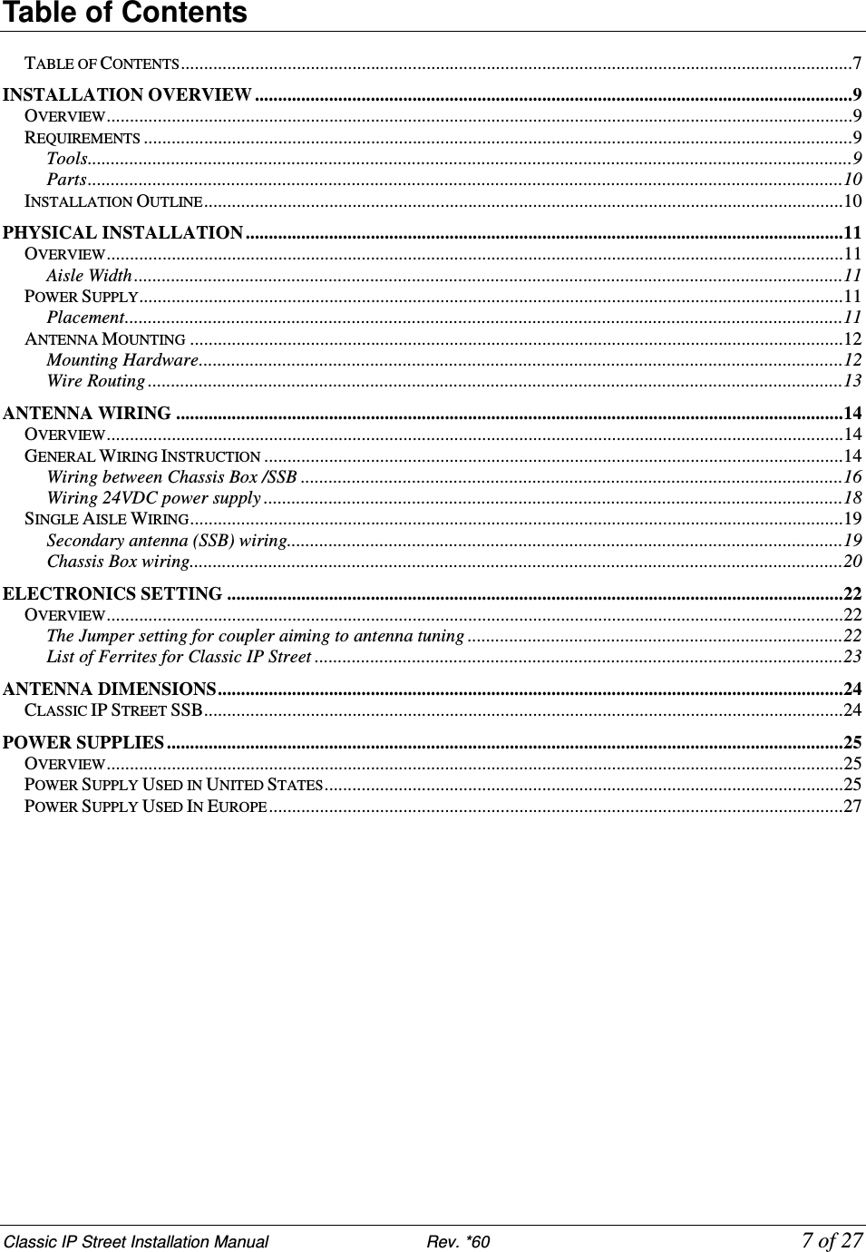
![Classic IP Street Installation Manual Rev. *60 11 of 27 C H A P T E R 3 PHYSICAL INSTALLATION Overview This chapter covers the physical placement and installation of the TR4210 antennas and power supply in the following sections: 1. Placement: How to determine the proper placement of the antennas. 2. Power Supply: Information on typical power supply placement. 3. Wire Routing: Information on typical wire routing methods. 4. Antenna Mounting: Antenna mounting information. Note: For details of placement, refer to Evolve installation manual, CKP P/N 7994249. Aisle Width The maximum aisle width for the Classic IP Street SSB antennas (with 410EP tag) is: Classic IP Street SSB – 2 m [6.6 ft] System performance is affected by aisle width and tag type. For aisle width details please refer to the TR4210 Product Reference Guide. Power Supply Classic IP Street SSB antennas utilize a +24 VDC power supply. Placement The Classic IP Street SSB antenna is designed to install on a standard 6.6 ft. opening. The minimum distance the chassis box and power supply can be from the antenna is 1.524m [5ft] while the maximum distance is 8m [26.4ft]. This distance should be taken into consideration when determining placement of the antenna, although optimal placement will vary from retail site to retail site. Placement Requirements: The power supply must be within 18m [60ft] of the furthest antenna. The power supply must be placed no higher than what is accessible from a store ladder.](https://usermanual.wiki/Checkpoint-Systems/EVOLVEREM/User-Guide-1646996-Page-11.png)
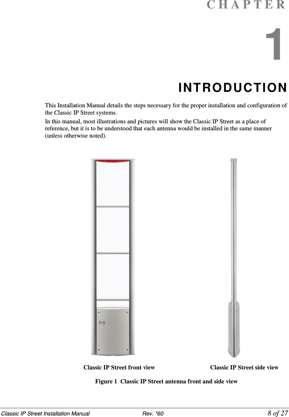
![Classic IP Street Installation Manual Rev.*60 12 of 27 If mounted in a plenum space, proper plenum rated wiring and plenum rated enclosures are required. The maximum operation temperature should be no more than 40 . Note: For more information about power supplies, please see “Power Supplies” on Appendix 2. Antenna Mounting Antennas are typically not mounted until after the finished flooring is in place. Mounting Hardware For mounting on Concrete Floor Utilize two (2) 1.3cm [.5in.] anchor bolts per antenna. Figure 2 Anchor Bolt (Concrete Mounting) Wood Floor Utilize two (2) 1.3cm [.5in] lag bolts per antenna. Figure 3 Lag Bolt (Wood Mounting)](https://usermanual.wiki/Checkpoint-Systems/EVOLVEREM/User-Guide-1646996-Page-12.png)
![Classic IP Street Installation Manual Rev.*60 13 of 27 Wire Routing Methods of Wire Routing Floor Trench: Typically 1.3cm [.5in.] wide by 3.8cm [1.5in.], but an increase in dimensions is recommended for more than two antennas. Wiremold: 1500 or 2600 series wire mold can be utilized. Typically wire mold is not used within customer traffic areas, so a typical placement is from the outside of the antennas to the doorframe. Conduit: 2.5cm [1in.] diameter conduit can be utilized in new construction situations. It is recommended that swept 90 degree angles are used, and that pull-strings are provided by the conduit installer. Wall / Mullion: Wires can be contained within mullions, and hollow walls for vertical wire runs. Dek-Duct / Panduit: Wires can be contained within surface mount Dek-Duct or Panduit for vertical wire runs. WARNING: Any wiring in plenum areas must be plenum rated. Additionally, ensure that the wire is installed in accordance with applicable (local/national) electrical codes.](https://usermanual.wiki/Checkpoint-Systems/EVOLVEREM/User-Guide-1646996-Page-13.png)
![Classic IP Street Installation Manual Rev. *60 25 of 27 A P P E N D I X 2 POWER SUPPLIES Overview This appendix covers all available (US and EU) TR4210 Street compatible power supplies. Details Power supplies have an output of +24 VDC. Requirements In the US, if the power supply is to be installed in a plenum (HVAC ventilation) area, the Globtek GS-599ES(R) and the Globtek GS-599MC-KIT(R) must be installed. Capacity The following power supplies can provide power for up to two aisle systems: Globtek GS-599 UF Globtek GS-599ES(R) EOS LFZVC65SG24E EOS- LFEVC65NS24PL (PN: 10102495) The following power supply can provide power for one aisle systems: EOS LFZVC36FS24S91 Power Supply Used in United States Model The US market uses the following power supply types: 1. Globtek GS-599ES(R) (PN: 7116509) Standard power supply rated for use in plenum areas. Note: For use in plenum areas, the Globtek GS-599MC-KIT(R) must be used in conjunction with the Globtek GS-599ES(R). Dimensions Width: 10.50cm [4.13in] Length: 15.24cm [6.00in] Height: 8.64cm [3.40in]](https://usermanual.wiki/Checkpoint-Systems/EVOLVEREM/User-Guide-1646996-Page-25.png)
![Classic IP Street Installation Manual Rev.*60 26 of 27 2. EOS- LFEVC65NS24PL (PN: 10102495) Note: Dimensions Width: 5.8 cm [2.284in] Length: 13.3 cm [5.236in] Height: 2.9 cm [1.152in] Weight 350 grams (12.35 ounces)](https://usermanual.wiki/Checkpoint-Systems/EVOLVEREM/User-Guide-1646996-Page-26.png)
![Classic IP Street Installation Manual Rev.*60 27 of 27 Power Supply Used In Europe Model The EU market uses one power supply types: EOS LFZVC36FS24S91 (PN: 7683707) Dimensions Length: 8.89cm [3.50in] Width: 2.42cm [0.95in] Height: 4.47cm [1.75in]](https://usermanual.wiki/Checkpoint-Systems/EVOLVEREM/User-Guide-1646996-Page-27.png)