Checkpoint Systems MPOSREADER RFID UHF Reader User Manual
Checkpoint Systems Inc RFID UHF Reader
User Manual

MOD POS READER TR4250
RFID POS READER V2 User’s Manual
10092348
Last Updated: April 29, 2014
Revision *
Checkpoint Systems International GmbH
Brentanostraße 27-29
69434 Hirschhorn
(06272)928-0

MOD POS READER TR4250
Copyright © 2014 by Checkpoint Systems, Inc.
Released April 29
Published by:
Checkpoint Systems International GmbH.
Brentanostraße 27-29
69434 Hirschhorn
Germany
RFID POS READER V2
Users Manual
Part Number: 10065513
Trademarks
Checkpoint is a registered trademark of Checkpoint Systems, Inc.
Other product and company names herein may be trademarks of their respective owners.
Other products © or ® their respective manufacturers or copyright holders.
Copyright and Warranty Information
The information in this guide is subject to change without notice.
Because of the changing nature of this product information presented in the RFID POS READER V2
Reader
Users Manual, Checkpoint Systems, Inc. is not liable for any omissions, misstatements, or
other errors of information.
The information presented in the Users Manual may not be copied, used or disclosed to others for the
purpose of procurement or manufacturing without the written permission of Checkpoint Systems, Inc.
This guide and the products discussed in this guide are the exclusive property of Checkpoint Systems
Inc. Copyright laws of the United States protects all information and products.
Copyright© 2011 Checkpoint Systems, Inc. All rights reserved.

Checkpoint Systems Intern. GmbH Company Confidential
Last Updated: 6/3/2014 11:10 AM 3 of 20
Table of contents
1REVISION CONTROL ....................................................................................... 4
1.1REVISION HISTORY ........................................................................................ 4
2BASIC SAFETY INFORMATION ............................................................................ 5
2.2NOTE ABOUT THE DISPOSAL OF OLD UNITS ................................................................ 6
3OPERATING INSTRUCTIONS .............................................................................. 6
3.1INTRODUCTION ............................................................................................ 6
3.2INSTALLATION ............................................................................................. 7
3.3ACCESSORIES .............................................................................................. 8
3.3.1Power Supply ..................................................................................... 8
3.3.2Antennae .......................................................................................... 8
3.4SETUP FOR TEST AND DEMO .............................................................................. 9
3.5BATTERY REPLACEMENT ................................................................................. 12
4TECHNICAL DATA ........................................................................................ 13
4.1MECHANICAL DATA ....................................................................................... 13
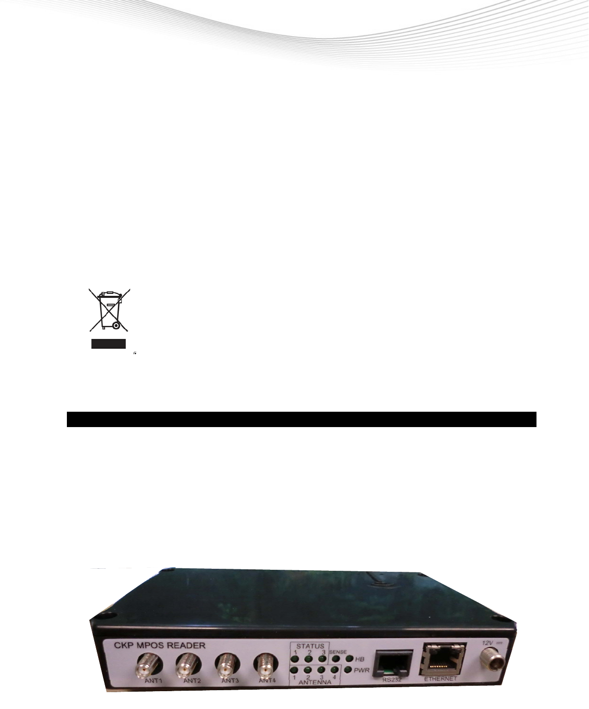
4.2FRONT VIEW ............................................................................................. 14
4.3REAR VIEW ............................................................................................... 14
4.4READER SPECIFICATIONS ................................................................................. 15
4.5ENVIRONMENT SPECIFICATIONS ........................................................................... 16
4.6DIGITAL I/O SPECIFICATION ............................................................................. 16
4.7ETHERNET LAN SPECIFICATION .......................................................................... 17
4.8RS-232 SPECIFICATIONS ................................................................................. 17
4.9USB SPECIFICATION ...................................................................................... 18
5ORDERING INFORMATION .............................................................................. 19
6GLOSSARY ................................................................................................. 19
7ANNEX DECLARATION OF CONFORMITY ............................................................. 20

Checkpoint Systems Intern. GmbH Company Confidential For Internal Use Only
Last Updated: 6/3/2014 11:10 AM 4 of 20
1 Revision Control
1.1 Revision History
Content changes to this document from its previous version to the current level are indicated by
Microsoft Word track changes bars (|) in the left margin of the document unless a complete rewrite
is indicated. Accept all tracked changes to the current document before updating it. This procedure
highlights the new changes made to the document by the author thus facilitating efficient review of
the document.
Revision
# Revision
Date Change Description and Explanation Created/Changed By
* 29/04/14 Hans-Günter Meuthen

Checkpoint Systems Intern. GmbH Company Confidential For Internal Use Only
Last Updated: 6/3/2014 11:10 AM 5 of 20
2 Basic safety information
Read these operating instructions before using the RFID POS READER V2 for the
first time! Make yourself completely familiar with the installation and operation of
the RFID POS READER V2 ! Retain these operating instructions for later
reference.
The RFID POS READER V2 is used for contact less reading of RFID (Radio
Frequency Identification) Tags. Only use the RFID POS READER V2 in the
manner described in these operating instructions!
Note all the detailed safety information given within the individual work steps.
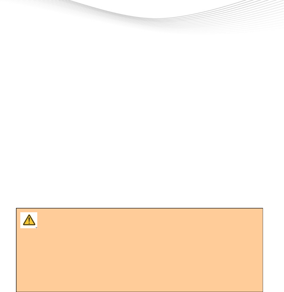
All safety information in these operating instructions is identified with the warning
symbol shown here.
Never use the RFID POS READER V2 in areas where there is a danger of
explosion.
Note that the electric installation of RFID POS READER V2 may only be done by
a professional.
It is essential to comply with the electrical, mechanical and climatic specifications
given in the Technical Data section. For further information see Chapter Technical
data.
Do not make any changes or modifications to the RFID POS READER V2. If
changes or modifications are made, all guarantee claims are voided. Furthermore,
the radio approval required for its operation is void!
Have a faulty RFID POS READER V2 inspected and repaired by our repair center.
Never make any repairs yourself under any circumstances.
Dispose of the RFID POS READER V2 properly after taking out of service. Never
put the RFID POS READER V2 into the normal household waste.
Federal Communications Commission (FCC) Approval Note:
This equipment has been tested and found to comply with the limits for a Class A digital device, pursuant to
part 15 of the FCC Rules. These limits are designed to provide reasonable protection against harmful
interference when the equipment is operated in a commercial environment. This equipment generates, uses,
and can radiate radio frequency energy and, if not installed and used in accordance with the instruction
manual, may cause harmful interference to radio communications. Operation of this equipment in a
residential area is likely to cause harmful interference in which case the user will be required to correct the
interference at his own expense.
Industry Canada Approval
This Class A digital apparatus complies with Canadian ICES-003.
Cet appareil numérique de la classe A est conforme à la norme NMB-003 du Canada.
This device complies with Industry Canada licence-exempt RSS standard(s). Operation is subject to the
following two conditions: (1) this device may not cause interference, and (2) this device must accept any
interference, including interference that may cause undesired operation of the device.
Checkpoint Systems Intern. GmbH Company Confidential For Internal Use Only
Last Updated: 6/3/2014 11:10 AM 6 of 20
Le présent appareil est conforme aux CNR d'Industrie Canada applicables aux appareils radio exempts de
licence. L'exploitation est autorisée aux deux conditions suivantes : (1) l'appareil ne doit pas produire de
brouillage, et (2) l'utilisateur de l'appareil doit accepter tout brouillage radioélectrique subi, même si le
brouillage est susceptible d'en compromettre le fonctionnement.
2.2 Note about the disposal of old units
Within the member countries of the European Union In accordance with the European
Union guideline 2002/96/EC, Checkpoint Systems takes back old devices within the member countries
of the European Union and disposes of them in an appropriate way. The devices concerned by this are
marked with the symbol shown aside.
For further information on the return procedure, please contact your local sales
contact. You will find the addresses of all sales partners in the internet on
www.checkpointsystems.com. Please take into consideration also the national
implementation of the EU guideline 2002/96/EC of your country.
For all other countries
Dispose of RFID POS READER V2 properly after taking out of service.
Observe the regulations valid in your country for the disposal of electronic devices.
Never put the RFID POS READER V2 into the normal household waste.
3 Operating Instructions
3.1 Introduction
RFID POS READER V2
is the electronics system of an Ultra High Frequency (UHF) radio
frequency identification (RFID) system (typically called an interrogator or reader) which
communicates with targets that are applied to or incorporated into an item. The targets
(typically referred to as tags or labels) serve to identify the item to which it is attached based
on a unique ID stored on the target.
Checkpoint Systems Intern. GmbH Company Confidential For Internal Use Only
Last Updated: 6/3/2014 11:10 AM 7 of 20
ATTENTION
The RFID POS READER V2 antenna ports may be susceptible to damage from static
discharge or other high voltage. Use proper Electrostatic Discharge (ESD) precautions to
avoid static discharge when handling or making connections to the RFID POS READER V2
antenna or communication ports. Equipment failure can result if the antenna or
communication ports are subjected to ESD.
3.2 Installation
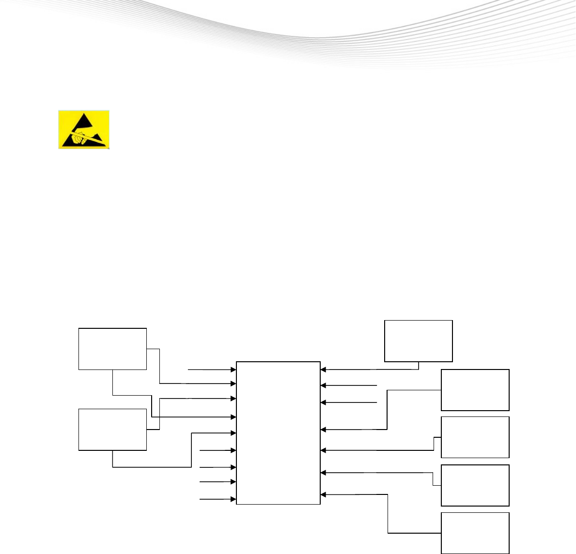
The RFID POS READER V2 is build in a Point of Sale System, for the installation guidelines refer to the
User Manual MODULAR POINT OF SALE SYSTEM.
Block Diagram of the Point of Sale System.
MOD POS
READER
TR4250
12V DC
USB OTG
RS232
TX/RX
ANTENNA
TX/RX
ANTENNA
TX/RX
ANTENNA
TX/RX
ANTENNA
AC/DC
ADAPTER
LAN with PoE
USB (UART1)
USB (UART2)
CASH
POINT 1
CASH
POINT 2
TRIGGER 1
TRIGGER 2
ANT 1
ANT 2
ANT 3
ANT 4
I/O 1
I/O 2
I/O 3
I/O 4

Checkpoint Systems Intern. GmbH Company Confidential For Internal Use Only
Last Updated: 6/3/2014 11:10 AM 8 of 20
3.3 Accessories
3.3.1 Power Supply
The RFID POS READER V2 can be powered either by suitable AC/DC-Adapter or by Power over
Ethernet (PoE). When using AC/DC-Adapter, PoE is switched off automatically.
RFID POS READER V2 does not have power switch. If it is necessary to switch off power, simply
unplug 12V DC connector or Ethernet Cable in case of PoE.
List of tested AC/DC-Adapter:
Model Manufacturer Description
GT-41082-1812-T2 GlobTek Inc.
Desktop Version
EPSA120100UE CUI INC Wall Plug EU-Version, modified with DC Plug
767K from Switchcraft
List of tested PoE:
Model Manufacturer Description
SF100D-08P V2 Cisco 8-way Network Switch
3504G PowerDsine 8-way Network Switch
3.3.2 Antennae
List of tested antennae:
Model Manufacturer Description
10052611 Checkpoint Systems PoS on Desk RFID only
10049661 Checkpoint Systems PoS on Desk RFID + RF combined
Checkpoint Systems Intern. GmbH Company Confidential For Internal Use Only
Last Updated: 6/3/2014 11:10 AM 9 of 20
10034527 Checkpoint Systems PoS under Desk RFID only
10090241 Checkpoint Systems PoS under Desk RFID + RF
10045992 Checkpoint Systems PoS under Desk shielded RFID only
10052028 Checkpoint Systems PoS on Desk Detacher RFID only
7378457 Checkpoint Systems PoS under Desk shielded deactivation PAD EU
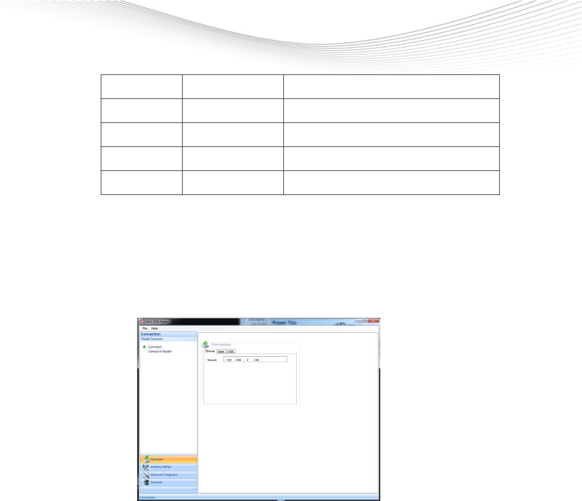
3.4 Setup for Test and Demo
- Set up PC with Checkpoint´s Demo Software
- Configure network adapter of PC with suitable IP-Address
- Connect power supply for reader and check if Power LED is on
- Connect antenna to port ANT1
- Put some RFID labels on antenna
- Link RFID POS READER V2 with Ethernet cable to PC
- Start Demo Software
- Connect reader
Checkpoint Systems Intern. GmbH Company Confidential For Internal Use Only
Last Updated: 6/3/2014 11:10 AM 10 of 20
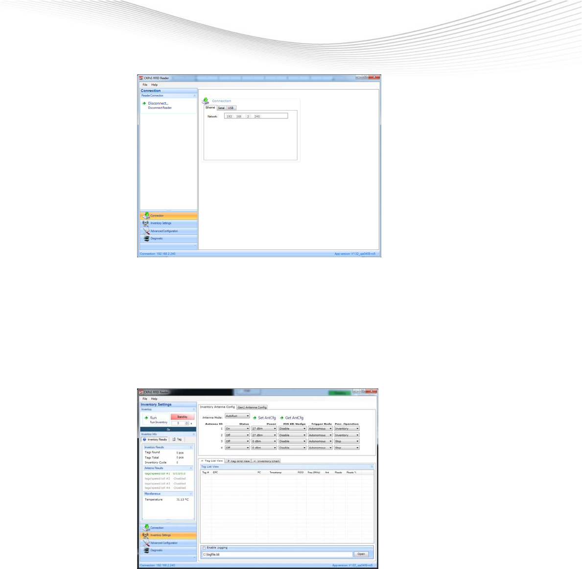
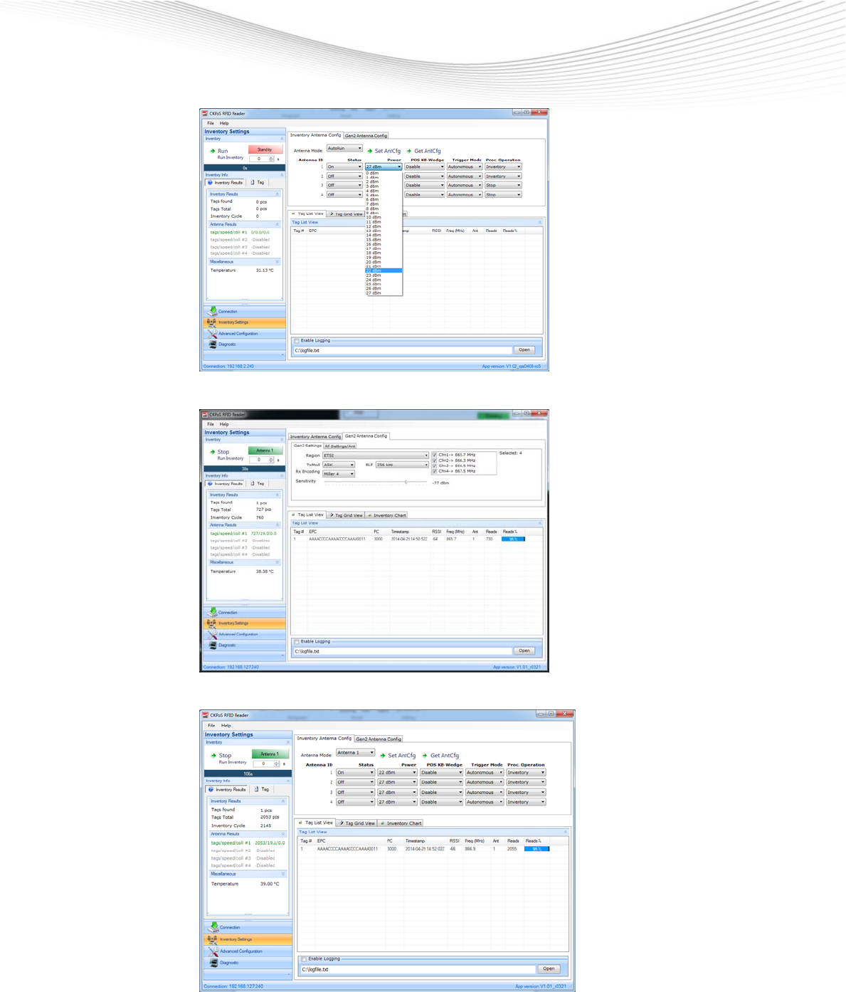
- Select: Inventory Settings
- Configure: Antenna Mode, RF-Power, Trigger Mode, etc.
Checkpoint Systems Intern. GmbH Company Confidential For Internal Use Only
Last Updated: 6/3/2014 11:10 AM 11 of 20
- Configure advanced Gen2 settings and start inventory
- TAGs in RF-field are listed in Tag List View
Checkpoint Systems Intern. GmbH Company Confidential For Internal Use Only
Last Updated: 6/3/2014 11:10 AM 12 of 20
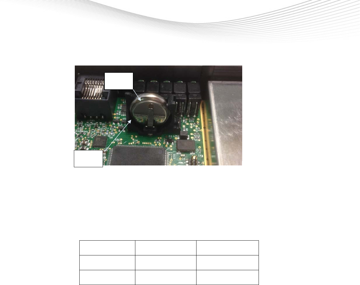
3.5 Battery Replacement
Picture shows battery in holder
- Battery: Coin Cell CR1632 3V 110mAh
- Before replacing battery measure battery voltage with voltmeter. New battery has 3V.
Buffered SRAM and clock work with voltage down to 2V. Replace battery so soon as
voltage is down to 2.2V
- Pull out discharged battery and replace it. Take care not to short-circuit Plus and
Minus.
- Check battery for right position
List of tested batteries
CR1632 Panasonic 140mAh
CR1632 Energizer 130mAh
CR1632 Renata 125mAh
Minus
Plus

Checkpoint Systems Intern. GmbH Company Confidential For Internal Use Only
Last Updated: 6/3/2014 11:10 AM 13 of 20
4 Technical Data
4.1 Mechanical Data
Size : 7.1 x 4.6 x 1.2 in (180 x 115 x 30 mm)
Weight: 0.7 lbs (320g)
Case material Plastic
Color Black
Connectors
Ethernet with PoE* RJ45 8pin *PoE Power over Ethernet
RS232 RJ45 8pin
DC-Input Barrel Type, 2.1/5.5/12.1 mm, center pin +
I/O Connector 4 x RJ12 6pin
Digital Inputs 2 x RJ12 6pin
USB1 OTG Micro AB 5pin
USB2 – USB3 Type B 4pin
ANT 1 – ANT 4 SMA-female
Checkpoint Systems Intern. GmbH Company Confidential For Internal Use Only
Last Updated: 6/3/2014 11:10 AM 14 of 20
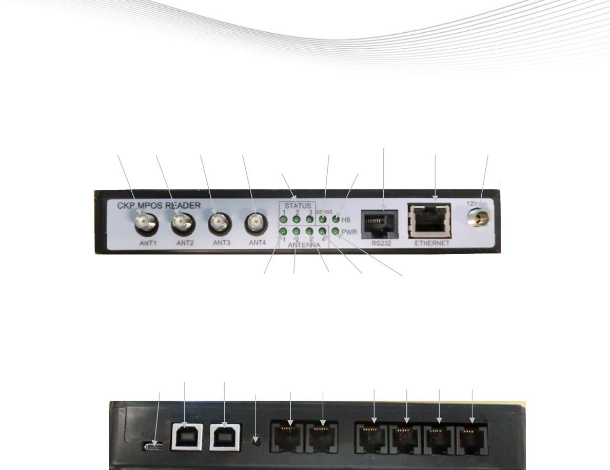
4.2 Front view
RS232 DC
ANT1 ANT2 ANT3 ANT4 TAG Connector LAN Connector
Status LED’s Heart Beat LED
ANT1 ANT2 ANT3 ANT4 Power On
LED LED LED LED LED
4.3 Rear view
USB1 USB2 USB3 RESET DIGILAL INPUTS DIGITAL INPUTS AND Outputs
OTG BUTTON IN1 IN2 I/O1 I/O2 I/O3 I/O4
Checkpoint Systems Intern. GmbH Company Confidential For Internal Use Only
Last Updated: 6/3/2014 11:10 AM 15 of 20
4.4 Reader Specifications
Power Connection
Input Voltage 12 VDC, Minimum 10V, Maximum 24V
Input current 0.75 A at 12 VDC
Power Consumption 3W ( typical while idle)
6 W ( typical at 500 mW conducted RF output power)
9 W ( Maximum with USB-Device and Digital Outputs powered )
Power over Ethernet (PoE)
IEEE class 802.3af 12.95W, LAN connector RJ45
RF Specifications
Frequency Range 865-868 MHz 902-928 MHz
RF Output Power max 500 mW conducted (27 dBm)
RF Output Power adjustment range 2 mW - 500 mW conducted (3 - 27 dBm) in 1dB steps
RF Output Power settings accuracy + - 1dB
RF Connections
RF Outputs 4
Impedance 50 Ohm
Caution: This device has been designed to operate with no more than 1 Watt into the antenna and an
antenna gain of no more than 6 dBic. Antenna having a higher gain is strictly prohibited per
regulations of Industry Canada, unless power into the antenna is decreased to compensate
for the increased antenna gain. The required antenna impedance is 50 ohms.
To reduce potential radio interference to other users, the antenna type and its gain should be
so chosen that the equivalent isotropic radiated power (EIRP) is not more than that required
for successful communication.
The installer of this radio equipment must ensure that the antenna is located or pointed such
that it does not emit an RF field in excess of Health Canada limits for the general
population; consult Safety Code 6, obtainable from Health Canada’s website at
www.hc-sc.gc.ca

Checkpoint Systems Intern. GmbH Company Confidential For Internal Use Only
Last Updated: 6/3/2014 11:10 AM 16 of 20
4.5 Environment Specifications
Operating temperature 23F to 113F ( -5C to 45C )
Storage temperature - 40F to 158F ( -40C to 70C )
Relative Humidity 5% to 95 % non-condensing
4.6 Digital I/O Specification
Cash Point Trigger (dual)
Connector RJ12 6P
2 Input 5 VDC, 1 mA Minimum 3V, Maximum 8V
Signals Pin 1 +5VDC
Pin 2 free
Pin 3 Digital IN
Pin 4 Digital IN
Pin 5 free
Pin 6 GND
LEDs & Buzzer (quad)
Connector RJ12 6P
1 Input 5 VDC, 1 mA
3 Outputs Open Collector (3 to 5 V, 20 mA Max)
Signals Pin 1 +5VDC
Pin 2 Digital OUT
Pin 3 Digital OUT
Pin 4 Digital OUT
Pin 5 Digital IN
Pin 6 GND

Checkpoint Systems Intern. GmbH Company Confidential For Internal Use Only
Last Updated: 6/3/2014 11:10 AM 17 of 20
4.7 Ethernet LAN Specification
Connector RJ-45
Ethernet 10/100 BaseT
Indicators Yellow Indicates link is operational
Green Indicates network traffic detected.
Signals Pin 1 TXD+ (Transmit Data +)
Pin 2 TXD- (Transmit Data -)
Pin 3 RXD+ (Receive Data +)
Pin 4 POE (Power over Ethernet)
Pin 5 POE (Power over Ethernet)
Pin 6 RXD- (Receive Data -)
Pin 7 POE (Power over Ethernet)
Pin 8 POE (Power over Ethernet
4.8 RS-232 Specifications
Connector RJ45
Baud rate 600 - 115200 (Default = 115200)
Parity None
Data bits 8
Stop bits 1
Signals Pin 1 RXD
Pin 2 TXD
Pin 3 GND
Pin 4 +3.3V
Pin 5 GND
Pin 6 Local Alarm Disable (Low active)
Pin 7 Reset (High active)
Pin 8 Global Alarm Disable (Low active)

Checkpoint Systems Intern. GmbH Company Confidential For Internal Use Only
Last Updated: 6/3/2014 11:10 AM 18 of 20
4.9 USB Specification
USB UART Converter (dual)
Connector Female USB Type B
Signals Pin 1 VCC (+5V)
Pin 2 - DATA
Pin 3 + DATA
Pin 4 GND
USB OTG
Connector Female USB Type Micro AB
Signals Pin 1 VCC (+5V max 500mA)
Pin 2 - DATA
Pin 3 + DATA
Pin 4 Identifier Pin
Pin 5 GND

Checkpoint Systems Intern. GmbH Company Confidential For Internal Use Only
Last Updated: 6/3/2014 11:10 AM 19 of 20
5 Ordering Information
The UHF-RFID Reader is available with the following number
Order Number: 10112394 RFID POS READER V2
6 Glossary
RFID Radio Frequency Identification.
EPC Electronic Product Code, a unique item identification number
EPC Global A new global standard that combines RFID technology, existing communications network
infrastructure and the Electronic Product Code to enable immediate and automatic
identification and tracking of an item through the whole supply chain globally, resulting in
improved efficiency and visibility of the supply chain

Checkpoint Systems Intern. GmbH Company Confidential For Internal Use Only
Last Updated: 6/3/2014 11:10 AM 20 of 20
7 Annex Declaration of Conformity
EMC limits and radio approvals
EMV for Short Range Device ETSI EN 301 489-3
Safety of equipment of low voltage device EN 60950-1
Approval for UHF RFID READER; Europe ETSI EN 302 208-1
Approval for Short Range Device; USA FCC 47 CFR Part 15
Approval for Short Range Device; Canada RSS 210 Issue 7