Checkpoint Systems NANOGATEAM AM Nano Gate User Manual 12 0033 Exhibit Cover
Alpha - High Theft Solutions, A Division of Checkpoint Systems, Inc. AM Nano Gate 12 0033 Exhibit Cover
Manual

5015 B.U. Bowman Drive Buford, GA 30518 USA Voice: 770-831-8048 Fax: 770-831-8598
Certification Exhibit
FCC ID: YWZ-NANOGATEAM
IC: 3356F-NANOGATEAM
FCC Rule Part: 15.209
IC Radio Standards Specification: RSS-210
ACS Project Number: 12-0033
Manufacturer: Alpha - High Theft Solutions
Model: NANOGATE-AM
Manual
www.alphaworld.com
Instructions for the Nano Gate
NANOGATE-AM
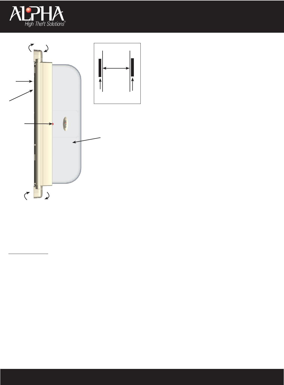
1. The Nano Gate can be installed on any at surface.
2. The Nano Gate can be installed with Power Cord up
or down.
3. The Nano Gate triggers 3 Alarm AM devices.
4. The red light indicates good power and serves as a
visual deterrent.
5. The Nano Gate can pivot side-to-side if bumped into.
6. The Nano Gate will alarm continuously if the
Pressure Switch comes off the wall.
NOTE: If power is removed, the Nano Gate will chirp
for 2 minutes.
7. The Nano Gate should not be placed within
4m (13’) of EAS systems
FACTS ABOUT THE NANO GATE:
• (1) Nano Gate - AM
• (1) Mounting Template
• (2) Brackets
• (4) P-Clips with Screws
• (10) Metal Screws
• (2) Caps
• (1) AC Power Cord - .6 m (2’) L
TOOLS SUPPLIED:
Clear Antenna
LED
Annunciator
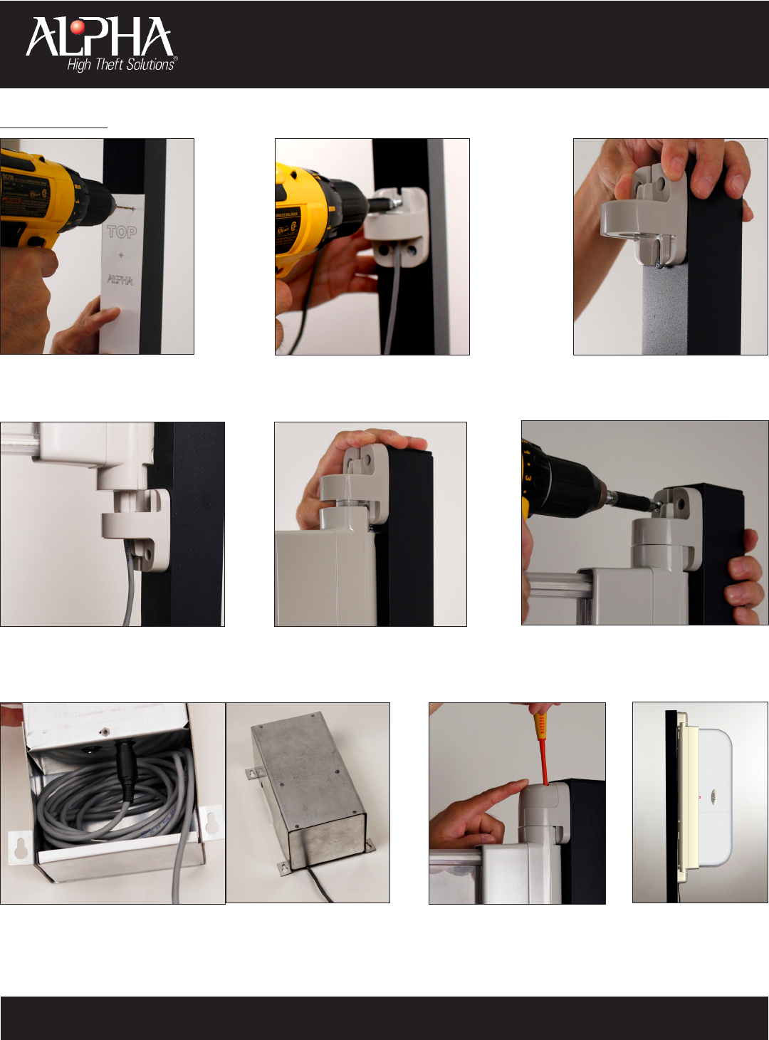
1. Place the provided Mounting Template onto a at surface with tape. The Mounting Template will be marked with
TOP and BOTTOM for placement and provides where the holes need to be drilled.
NOTE: Must mount Nano Gate at least 0.91 m (3 feet) from oor
2. Drill 6 holes as indicated on the template. (Fig. 1)
3. Remove the template. You should have 3 holes on top and 3 holes on bottom.
4. Screw bottom bracket in place with 3 screws. (Fig. 2)
5. Screw in the top screw only - allowing space for the Bracket to slide. (Fig. 3)
6. Insert bottom end of the Nano Gate into the bottom Bracket. (Fig. 4)
7. Push the top Bracket down onto the Nano Gate. (Fig. 5)
Screw remaining screws into top Bracket. (Fig. 6)
8. Plug power supply cord in power box and wind extra cable into storage box. Mount storage box. (Fig. 7)
Place the Caps on the top and bottom end of the Nano Gate and screw in with the 4 small screws provided. (Fig. 8)
NOTE: Once the Nano Gate is ush to the wall the unit will chirp to indicate the Pressure Switch is engaged and the unit is armed.
9. The Nano Gate is now installed. (Fig. 9)
NOTE: 1.83 m (6’) coverage requires mounting Nano Gate in off-set locations on the door. (See Diagram 1)
INSTALLATION:
1.83 m
(6’)
Diagram 1
1.06 m
(3.5’)
.91 m
(3’)
Pivoting Antenna
Pressure
Switch
TOOLS REQUIRED:
• Electric Hand Drill
• 1/8” Drill Bit
• Phillips PH0 Screw
Driver
• Tape Measure
• Tape
Pivoting Antenna
www.alphaworld.com
Instructions for the Nano Gate
NANOGATE-AM
PAGE 2
Figure 1 - Drill holes as indicated
on template.
Figure 2 - Screw in bottom Bracket.
Figure 4 - Insert bottom end of Nano Gate
into bottom Bracket.
Figure 3 - Screw in top screw only -
allowing space for the Bracket to
slide on.
Figure 7 - Plug power supply cord in power box and wind extra cable
into storage box. Mount storage box.
Figure 6 - Screw remaining screws into top
Bracket.
INSTALLATION:
Figure 8 - Screw in both top and
bottom Caps.
Figure 5 - Push top Bracket down
onto Nano Gate.
Figure 9 - Nano Gate is
now installed.

Warning: Changes or modications to this device not expressly approved by Alpha High Theft Solutions could void the user’s authority to operate
the equipment.
NOTE: This equipment has been tested and found to comply with the limits for a Class B digital device, pursuant to Part 15 of the FCC Rules.
These limits are designed to provide reasonable protection against harmful interference in a residential installation. This equipment generates,
uses, and can radiate radio frequency energy and, if not installed and used in accordance with the instructions, may cause harmful interference to
radio communications. However, there is no guarantee that interference will not occur in a particular installation. If this equipment does cause
harmful interference to radio or television reception, which can be determined by turning the equipment off and on, the user is encouraged to
try to correct the interference by one or more of the following measures:
• Reorient or relocate the receiving antenna.
• Increase the separation between the equipment and receiver.
• Connect the equipment into an outlet on a circuit different from that to which the receiver is connected.
• Consult the dealer or an experienced radio/TV technician for help.
Under Industry Canada regulations, this radio transmitter may only operate using an antenna of a type and maximum (or lesser) gain approved for
the transmitter by Industry Canada. To reduce potential radio interference to other users, the antenna type and its gain should be so chosen that
the equivalent isotropically radiated power (e.i.r.p.) is not more than that necessary for successful communication.
Conformément à la réglementation d’Industrie Canada, le présent émetteur radio peut fonctionner avec une antenne d’un type et d’un gain maximal
(ou inférieur) approuvé pour l’émetteur par Industrie Canada. Dans le but de réduire les risques de brouillage radioélectrique à l’intention des autres
utilisateurs, il faut choisir le type d’antenne et son gain de sorte que la puissance isotrope rayonnée équivalente (p.i.r.e.) ne dépasse pas l’intensité
nécessaire à l’établissement d’une communication satisfaisante.
This device complies with Industry Canada licence-exempt RSS standard(s). Operation is subject to the following two conditions: (1) this device may
not cause interference, and (2) this device must accept any interference, including interference that may cause undesired operation of the device.
Le présent appareil est conforme aux CNR d’Industrie Canada applicables aux appareils radio exempts de licence. L’exploitation est autorisée aux deux
conditions suivantes : (1) l’appareil ne doit pas produire de brouillage, et (2) l’utilisateur de l’appareil doit accepter tout brouillage radioélectrique
subi, même si le brouillage est susceptible d’en compromettre le fonctionnement.
www.alphaworld.com
Instructions for the Nano Gate
NANOGATE-AM
PAGE 3