Checkpoint Systems TPRO7100 Tag Pad Serial User Manual PROInstallproc
Checkpoint Systems Inc Tag Pad Serial PROInstallproc
PROInstallproc

813910 NOTICE TO PERSONS RECEIVING THIS DRAWING
AND/OR TECHNICAL INFORMATION:
Title: INSTALLATION PROCEDURE
TPRO7100 AND TPRO7200
Checkpoint Systems claims proprietary rights to the material disclosed hereon.
This drawing and/or technical information is issued in confidence for engineering
information only and may not be reproduced or used to manufacture anything
shown or referred to hereon without direct written permission from Checkpoint
Systems to the user. This drawing and/or technical information is the property
of Checkpoint Systems and is loaned for mutual assistance, to be returned
when its purpose has been served.
THIS DRAWING AND/OR TECHNICAL INFORMATION IS THE
PROPERTY OF CHECKPOINT SYSTEMS, INC.
Revisions Revisions
Rev Description Date Engineer Rev Description Date Approved
*60 CR2475B 12/20/00 P. WILHELM
Doc Mgr.: J. HUG Date: 9/13/00
Dwn: P. WILHELM Date: 9/13/00
741407 Chk: Date:
280116 Eng: P.WILHELM Date: 9/13/00 Size A 813910
Used On Appd: R. SALESKY Date: 9/13/00 Scale: N/A 2000 Checkpoint Systems, Inc. Page 1 of 10

INSTALLATION PROCEDURE,
TPRO7100 AND TPRO7200
____________________________________________________________________________________________________________________________
CHECKPOINT SYSTEMS, INC. CONFIDENTIAL AND PROPRIETARY INFORMATION, FOR INTERNAL USE ONLY.
Dwg. No. 813910 Rev. *60 Page 2
TABLE OF CONTENTS
1.0 INTRODUCTION.................................................................................................................................3
1.1 OPERATIONAL OVERVIEW OF THE TPRO7100 AND TPRO7200...........................................................................3
1.2 SYSTEM CONFIGURATION .........................................................................................................................................3
2.0 EFFECTS OF NOISE IN THE INSTALLATION ENVIRONMENT..................................................4
2.1 EFFECTS OF NOISE ON THE TPRO7100 AND TPRO7200 SYSTEM........................................................................ 4
2.2 TYPES OF NOISE SOURCES.........................................................................................................................................4
2.3 TYPICAL ACTIVE NOISE SOURCES ........................................................................................................................... 4
2.4 PASSIVE NOISE SOURCES........................................................................................................................................... 5
3.0 PRE-INSTALLATION.........................................................................................................................5
4.0 INSTALLATION..................................................................................................................................5
4.1 SERVICE PERSONNEL..................................................................................................................................................5
4.2 TOOLS FOR SET UP....................................................................................................................................................... 5
4.3 TPRO7100 AND TPRO7200 CONNECTIONS............................................................................................................... 6
1. POWER CONNECTIONS............................................................................................................................................. 6
2. BAR CODE SCANNER CONNECTIONS (TPRO7200 ONLY)......................................................................................6
3. NETWORK CONNECTIONS (TPRO7200 ONLY)........................................................................................................ 6
5.0 TPRO7200 SINGLE BOARD COMPUTER........................................................................................6
6.0 BASEBAND SIGNALS........................................................................................................................6
7.0 SERVICE..............................................................................................................................................7
7.1 MAINTENANCE............................................................................................................................................................. 7
7.2 TROUBLESHOOTING.................................................................................................................................................... 7
7.3 SPARE PARTS FOR SERVICE ......................................................................................................................................7
8.0 DIAGRAMS.........................................................................................................................................7
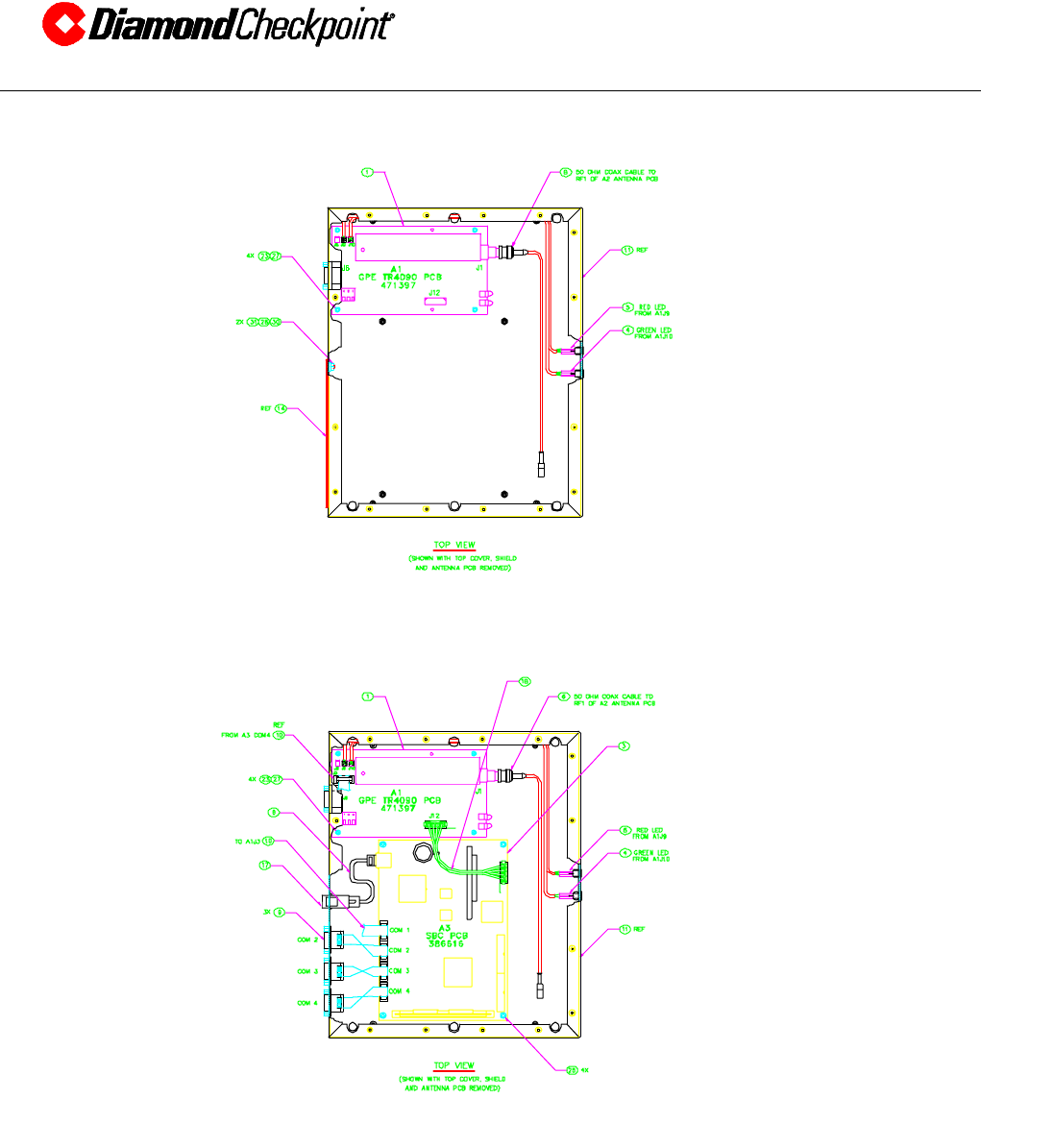
8.1 TPRO7100 WIRING DIAGRAM.......................................................................................................................................7
8.2 TPRO7200 WIRING DIAGRAM.......................................................................................................................................7
8.2 BASEBAND MEASUREMENT AT TP1 OF TR4090 BOARD........................................................................................ 9
9.0 OPTIONAL BARCODE SCANNER SETUP (TPRO7200 ONLY) ....................................................9
10.0 JUMPER AND SWITCH SETTINGS FOR THE SBC (TPRO7200 ONLY).......................................9
10.1 JUMPER SETTINGS .......................................................................................................................................................9
10.2 MISCELLANEOUS SETTINGS ...................................................................................................................................... 9
11.0 TPRO7100 AND TPRO7200 ANTENNA TUNING PROCEDURE.................................................10

INSTALLATION PROCEDURE,
TPRO7100 AND TPRO7200
____________________________________________________________________________________________________________________________
CHECKPOINT SYSTEMS, INC. CONFIDENTIAL AND PROPRIETARY INFORMATION, FOR INTERNAL USE ONLY.
Dwg. No. 813910 Rev. *60 Page 3
1.0 INTRODUCTION
This document provides the procedures required to install the TPRO7100 and the TPRO7200
readers. The installer should carefully read the section entitled “Effects Of Noise In The
Installation Environment” to gain an understanding of the environmental factors which may affect
system performance prior to attempting the installation. Techniques for reducing negative
environmental effects are also discussed in this section. The possible sources of interference for
an RFID system are similar to a standard Electronic Article Surveillance (EAS) system. One key
improvement is that the system has been designed to be immune to resonances and false alarms.
1.1 OPERATIONAL OVERVIEW OF THE TPRO7100 AND TPRO7200
The TPRO7100 and TPRO7200’s function is to read RFID tags which contain product
information. The TPROs read RFID tag data within twelve inches above the reader’s
surface.
The TPRO7100 consists of a TR4090 transceiver board and an antenna whereas the
TPRO7200 is composed of a TR4090, a single board computer (SBC), and an antenna.
The TR4090 continuously drives the antenna at a carrier frequency of 13.56MHz.
The antenna field powers the RFID tag. Once the tag has power, it sends out information
by tuning and detuning its resonant circuit. When tuned, the tag loads the reader antenna
which causes small amplitude perturbations of the reader field. The transceiver receives
this signal using AM detection, applies gain, and filters the signal.
In a TPRO7100, the TR4090 converts tag data to ASCII and transmits this data over its
serial port to a host PC.
In a TPRO7200, , the TR4090 converts tag data to ASCII and transmits this data over its
serial port to the SBC. The SBC in turn sends the data to a server over a 10base-T
Ethernet link. In addition to the RS-232 communications to the TR4090, the SBC
provides RS-232 communications to an external bar code scanner and a data terminal.
The bar code scanner is used to enter information which is associated with tag data that is
read by the TPRO7200.
1.2 SYSTEM CONFIGURATION
The TPROs consist of as many as 5 major components. These are:
1. Antenna
2. TR4090 transceiver board
3. Power Supply (External wall pack)
4. Single Board Computer (TPRO7200 only)
5. Bar Code Scanner (TPRO7200 only)

INSTALLATION PROCEDURE,
TPRO7100 AND TPRO7200
____________________________________________________________________________________________________________________________
CHECKPOINT SYSTEMS, INC. CONFIDENTIAL AND PROPRIETARY INFORMATION, FOR INTERNAL USE ONLY.
Dwg. No. 813910 Rev. *60 Page 4
2.0 EFFECTS OF NOISE IN THE INSTALLATION ENVIRONMENT
The following discussion on noise sources and the effects of noise on the system are provided
primarily to make the installer of the system aware of potential pitfalls when installing the
TPRO7100 or TPRO7200 equipment. However, the TPRO7100/7200 antenna is designed in
such a way that the reader can be placed on a metal counter without degradation of performance.
For the same reason, passive noise sources in general should not be detrimental to the
performance unless placed directly on top of the reader antenna section.
2.1 EFFECTS OF NOISE ON THE TPRO7100 AND TPRO7200 SYSTEM
The TPRO7100/7200 "listens" for very small field disturbances caused by the presence of
a tag. Since these signals are very small, it is possible to drown these signals in noise
produced by different types of equipment or noise produced by metallic objects in the
immediate vicinity of the system’s antenna.
Once it is understood what the typical problems are, the Customer Service Engineer (CSE)
will find that avoiding these problems simplifies the installation process.
2.2 TYPES OF NOISE SOURCES
In the typical field environment, different noise sources will be encountered. Devices
such as electric motors, transformers, electric lines, etc., radiate alternating magnetic
fields. These devices will generally be referred to as "active sources".
If metallic objects are within (to the sides and above) 1 foot of the system’s antenna, they
will be "excited" by the system’s transmitted field. This will create noise in the system’s
antenna if the metallic object(s) is being mechanically or acoustically vibrated. As
opposed to the previously described active noise sources, these objects only re-radiate the
system’s signal and are therefore called "passive noise sources". This reflected noise
impairs the system’s sensitivity and may cause the system to miss a tag detection
opportunity.
Provided the mechanism that causes the disturbances are understood and that one is
familiar with the type of equipment / objects that cause these problems, it is quite simple
to avoid these pitfalls.
2.3 TYPICAL ACTIVE NOISE SOURCES
Provided that the distances between the system and the possible noise source(s) indicated
above are maintained, no special problems should be encountered.
The types of equipment typically responsible for system disturbances in a field
environment are:
• Transformers or high current AC cables within 6 feet (2 meters) from the antenna.
• Escalators within approximately 6 feet (2 meters) from the antenna.
• Electronic equipment in general, within approximately 6 feet (2 meters) from the
antenna.
• Cash registers within approximately 3 feet (1 meter) from the antenna.
• Neon signs or fluorescent tubes within approximately 3 feet (1 meter) from the
antenna.

INSTALLATION PROCEDURE,
TPRO7100 AND TPRO7200
____________________________________________________________________________________________________________________________
CHECKPOINT SYSTEMS, INC. CONFIDENTIAL AND PROPRIETARY INFORMATION, FOR INTERNAL USE ONLY.
Dwg. No. 813910 Rev. *60 Page 5
2.4 Passive Noise Sources
Passive noise sources can cause decreased sensitivity and lead to poor metal
discrimination and ultimately false alarms. Metal objects cause this. A few typical
examples of metal found near an RFID system include:
• Frames in counters.
• Metal objects that can be placed in a counter after installation.
• Metal dust bins.
• Metal displays.
• Security gates, especially the closed loop sections.
• Metal cabinets.
• Door frames, especially closed loops.
• Metal tubes/structures hidden in walls.
• Metal structures on other side of wall (therefore not visible and uncontrollable).
• Sheet metal surfaces.
• Metal window frames, especially closed loops.
3.0 PRE-INSTALLATION
The following items should be checked by the CSE prior to installation. Careful attention to these
tips will minimize post installation issues.
• A qualified technician should conduct a site survey before contracting and installation.
• Quality of the AC ground can have considerable effect on the RFID system sensitivity. The
system should be electrically connected to a dedicated AC line. No other device should be
connected at this point in order to diminish the risk of poor performance. An AC filter is
supplied in the power supply to help alleviate this problem and to ensure the unit complies
with EMC standards for both conducted immunity and conducted emissions.
4.0 INSTALLATION
4.1 SERVICE PERSONNEL
This product should only be installed and serviced by personnel properly trained to:
• Read wiring diagrams
• Use electronic test equipment
• Make electronic wiring connections
• Use hand and small power tools
• Fault find on live equipment
CAUTION: Installing this product involves working while AC power is on. Take proper
precautions to ensure a safe condition and at all times avoid accidental contact. It is
extremely important that the instructions in this manual are followed carefully.
4.2 TOOLS FOR SET UP
• Dual channel oscilloscope, > 50 MHz, preferably battery powered.

INSTALLATION PROCEDURE,
TPRO7100 AND TPRO7200
____________________________________________________________________________________________________________________________
CHECKPOINT SYSTEMS, INC. CONFIDENTIAL AND PROPRIETARY INFORMATION, FOR INTERNAL USE ONLY.
Dwg. No. 813910 Rev. *60 Page 6
• Digital voltmeter "universal type DVM”
• A BNC to SMB interface cable
• Frequency counter capable of resolving 1 Hz at 13.56 MHz
4.3 TPRO7100 AND TPRO7200 CONNECTIONS
The TPROs are delivered with:
• External 12V wall pack power supply
• Optional Bar code scanner (TPRO7200 only)
The TPRO7200 has a connector panel on the side.
Install the peripherals as follows:
1. Power Connections
• Connect the 12V wall pack power supply to the power jack.
2. Bar Code Scanner Connections (TPRO7200 only)
• Connect the bar code scanner to the connector labeled “COM 4”.
• Plug the bar code scanner power supply into an AC outlet (120V, 60Hz).
3. Network Connections (TPRO7200 only)
• Connect the network cable to the RJ-45 connector on the connector panel.
5.0 TPRO7200 SINGLE BOARD COMPUTER
The SBC is the interface controller for the following tasks:
• Communication of read only RFID tag data via 10Base-T ethernet or bar code data via
RS-232 to the application server.
The SBC interface connections are described in the table below.
SBC Interface Table
Cable SBC TR4090 Connector Panel
Function Connector Panel
Label Connector Type
COM1 J1 J6
COM2 J2 DIAGNOSTIC COM 2 9 pin M
MiniD-Sub
COM3 J3 PASS THRU COM 3 9 pin M
MiniD-Sub
COM4 J4 BARCODE COM 4 9 pin M
MiniD-Sub
Ethernet J13 ETHERNET ETHERNET RJ-45
Power J6 J2
Antenna J1
6.0 BASEBAND SIGNALS
It is possible to observe baseband signals and noise at two locations. The noise floor you will
observe is comparable to what can be seen in EAS systems.

INSTALLATION PROCEDURE,
TPRO7100 AND TPRO7200
____________________________________________________________________________________________________________________________
CHECKPOINT SYSTEMS, INC. CONFIDENTIAL AND PROPRIETARY INFORMATION, FOR INTERNAL USE ONLY.
Dwg. No. 813910 Rev. *60 Page 7
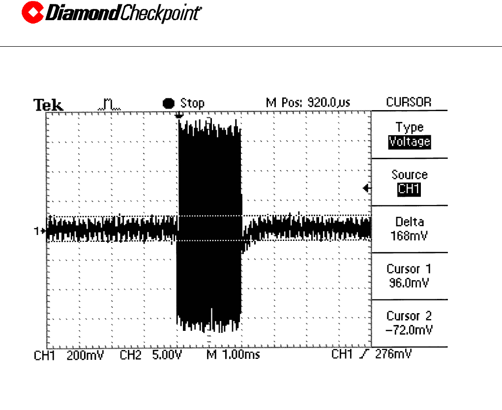
1. Attach your SMB to BNC cable to TP1 on the TR4090 board.
2. Set your scope to 100 mV vertical, 1 ms horizontal.
3. The noise floor will typically be between 50 to 100 mVpp in a “clean” environment.
4. The tag signal should always be at least twice the amplitude of the noise.
5. See section 8 of this document for how the tag signature should look.
7.0 SERVICE
7.1 MAINTENANCE
No routine maintenance is necessary on this system though the system should be tested
periodically to ensure it is in safe working condition and that performance requirements
are satisfactory.
7.2 TROUBLESHOOTING
1. System does not work:
Check the fuse on the TR4090 indie the TPRO7100 or TPRO7200 and try again
2. No field is being generated:
Verify that the TR4090 is getting 12 volts
3. No baseband signals are visible at TP1 on the TR4090:
Replace the TR4090 board
4. Noise Level:
In a location with high levels of noise, always try to remoce the source of the noise first.
For instance, if the noise-source is a cash register near the system, position the cash
register further away from the system’s antenna.
5. Fuse on TR4090 keeps blowing:
Replace with a fuse fo same type and rating. If it blows again, try to fault-find the
problem. If you can’t solve the problem, then replace the board at fault.
6. Poor detection:
Make sure the antenna is tuned (see section 12)
7.3 SPARE PARTS FOR SERVICE
• TR4090, Part # 109210
• Single Board Computer, Part# 443702
• TPRO7100/TPRO7200 wall pack, Part# 856612
8.0 DIAGRAMS
This section includes wiring diagrams for the TPRO7100 and the TPRO7200 as well as a ‘scope
shot’ of the base band signal measured at TP1 of the TR4090.
8.1 TPRO7100 WIRING DIAGRAM
INSTALLATION PROCEDURE,
TPRO7100 AND TPRO7200
____________________________________________________________________________________________________________________________
CHECKPOINT SYSTEMS, INC. CONFIDENTIAL AND PROPRIETARY INFORMATION, FOR INTERNAL USE ONLY.
Dwg. No. 813910 Rev. *60 Page 8
8.2 TPRO7200 WIRING DIAGRAM
INSTALLATION PROCEDURE,
TPRO7100 AND TPRO7200
____________________________________________________________________________________________________________________________
CHECKPOINT SYSTEMS, INC. CONFIDENTIAL AND PROPRIETARY INFORMATION, FOR INTERNAL USE ONLY.
Dwg. No. 813910 Rev. *60 Page 9
8.3 BASEBAND MEASUREMENT AT TP1 OF TR4090 BOARD
9.0 OPTIONAL BARCODE SCANNER SETUP (TPRO7200 ONLY)
Bar Code Scanner: Metrologic MS951 Hand-Held laser Scanner
Interface: Serial (RS-232)
Refer to the MS951 Programming Guide.
1. Scan in the bar code at the top of page 4 entitled “Enter/Exit Program Mode”.
2. Scan in the bar code entitled “Short Range Activation Out of the Stand” on page 4.
3. Scan in the bar code entitled “Transmit Start/Stop” on page 41.
4. Scan in the bar code at the top of page 4 entitled “Enter/Exit Program Mode”.
10.0 JUMPER AND SWITCH SETTINGS FOR THE SBC (TPRO7200 ONLY)
10.1 JUMPER SETTINGS

INSTALLATION PROCEDURE,
TPRO7100 AND TPRO7200
____________________________________________________________________________________________________________________________
CHECKPOINT SYSTEMS, INC. CONFIDENTIAL AND PROPRIETARY INFORMATION, FOR INTERNAL USE ONLY.
Dwg. No. 813910 Rev. *60 Page 10
Refer to the SBC board schematic for the following:
1. Jumper pins 2 & 3 of J5 (select “WDOG”)
2. Jumper pins 1 & 2 of J17 (select “+5V”)
3. Jumper pins 2 & 3 of J24 (select “COM2”)
4. Jumper J14 (Connects the RTC battery)
5. Jumper J20 pins 11 &12 (selects IRQ0 for the PC104 sound card)
6. Jumper J18, J21, and J22 to the “RS-232” position (pin 2 to pin 3)
10.2 MISCELLANEOUS SETTINGS
Set switches SW2 1 and SW2 3 to “ON” and SW2 2 to off (4 is not used).
11.0 TPRO7100 And TPRO7200 Antenna Tuning Procedure
Tuning the TPRO7100 and TPRO7200 antenna involves adjusting a piston capacitor on the
antenna.
1. Supply power to the TPRO7100 or TPRO7200 using the appropriate wall pack.
2. Adjust the piston capacitor to maximize the distance from the antenna that the tag reads. You
will know that a tag has been read when you see the red LED on the side of the reader blink.
This distance should be > 8 inches when the tag is parallel to the antenna (you should be able
to adjust for at least a 10 inch read range).