Checkpoint Systems TR7240 Module for EAS Detection System User Manual CE logo small eps
Checkpoint Systems Inc Module for EAS Detection System CE logo small eps
Contents
user manual
TR7240User Manual Rev.00
1 of 10
10068416
NOTICE TO PERSONS RECEIVING THIS DRAWING
AND/OR TECHNICAL INFORMATION:
Title: USER’S MANUAL
Checkpoint Systems claims proprietary rights to the material disclosed hereon.
This drawing and/or technical information is issued in confidence for
engineering information only and may not be reproduced or used to manufacture
anything shown or referred to hereon without direct written permission
from Checkpoint Systems to the user. This drawing and/or technical information
is the property of Checkpoint Systems and is loaned for mutual
assistance, to be returned when its purpose has been served.
THIS DRAWING AND/OR TECHNICAL INFORMATION IS THE
PROPERTY OF CHECKPOINT SYSTEMS, INC.
TR7240 TX/RX
REVISIONS
REVISIONS
REV DESCRIPTION DATE ENGINEER REV DESCRIPTION DATE APPROVED
00 TBD 10/30/13
P. VACHRANUKUNKIET
DOC SPEC
DWN
CHK
10077443
ENG
P. VACHRANUKUNKIET
Size A
10068416
Used On
APPD
Scale: N/A Checkpoint Systems, Inc. 2013
11T
Page 1 of 31
Important Information to our Users in North America
FCC Regulatory Compliance Statement
Checkpoint Systems, Inc., offers Electronic Article Surveillance (EAS) or Radio Frequency Identification Products
that have been FCC certified or verified to 47 CFR Part 15 Subparts B/C. Appropriately, one of the following labels
will apply to the approval:
NOTE: This equipment has been tested and found compliant within the limits for a class A digital
device, pursuant to Part 15 of the FCC Rules. These limits are designed to provide reasonable
protection against harmful interference when the equipment is operated in a commercial
environment. This equipment generates, uses, and can radiate interference to radio
communications. Operation of this equipment in a residential area is likely to cause harmful
interference in which case the user will be required to correct the interference at own expense.
- OR -
This device complies with Part 15 of the FCC Rules. Operation is subject to the following two
conditions: (1) including this device may not cause harmful interference, and (2) this device must
accept any interference received, including interference that may cause undesired operation, which
may include intermittent decreases in detection and/or intermittent increases in alarm activity.
Industry Canada Regulatory Compliance Statement
This device complies with the Industry Canada license-exempt RSS standard(s). Operation is subject to the
following two conditions:
1. This device may not cause interference, and
2. This device must accept any interference, including interference that may cause undesired operation of the
device.
Le fonctionnement de l’ appareil est soumis aux deux conditions suivantes:
(1) Cet appareil ne doit pas perturber les communications radio, et
(2) cet appareil doit supporter toute perturbation, y compris les perturbations qui pourraient provoquer son
dysfonctionnement.
Equipment Safety Compliance Statement
Checkpoint’s Electronic Article Surveillance (EAS) products have been designed for safeness during normal use
and, where applicable have been certified, listed, or recognized in accordance with one or more of the following
safety standards; UL 60950-1, CSA C22.2 No. 60950-1-07. Additional approvals may be pending.
WARNING: Changes or modifications to Checkpoint’s EAS equipment not expressly approved by the party
responsible for assuring compliance could void the user’s authority to operate the equipment in a safe or otherwise
regulatory compliant manner.
Equipment Compliance Statement
WARNING: Changes or modifications to Checkpoint’s EAS or Radio Frequency Identification (RFID) equipment not
expressly approved by the party responsible for assuring compliance could void the user’s authority to operate the
equipment in a safe or otherwise regulatory compliant manner.

TR7240User Manual Rev.00
3 of 10
Important Information to our Users in Europe
CE Regulatory Compliance Statement
Where applicable, Checkpoint Systems, Inc. offers certain Electronic Article Surveillance (EAS) products
that have CE Declarations of Conformity according to R&TTE Directive 99/5/EC, EMC Directive
2004/108/EC, and Low Voltage Directive 2006/95/EC.
System Electromagnetic Compatibility (EMC) has been tested and notified through Spectrum Management
Authorities if necessary, using accredited laboratories, whereby, conformity is declared by voluntarily
accepted European Telecommunications Standards Institute (ETSI) standards EN 301489-3 and EN
302208 and/or EN 300330, as applicable.
NOTE: Certain Electronic Article Surveillance (EAS) equipment have been tested and
found to conform to the CE emission and immunity requirement in Europe. This equipment
generates, uses, and can radiate radio frequency energy and, if not installed and used in
accordance with the instruction manual, may cause harmful interference to radio
communications. Under unusual circumstances, interference from external sources may
degrade the system performance, which may include intermittent decreases in detection
and/or intermittent increases in alarm activity. However, there is no guarantee that
interference will not occur in a particular installation. If this equipment experiences frequent
interference from external sources or does cause harmful interference to radio
communications reception, which can be determined by turning the equipment off and on,
please contact a Checkpoint Systems representative for further assistance.
RoHS Compliance Statement
The RoHS Directive stands for "the restriction of the use of certain hazardous substances in electrical and
electronic equipment." A RoHS compliant product means that electrical and electronic equipment cannot
contain more than maximum permitted levels of lead, cadmium, mercury, hexavalent chromium,
polybrominated biphenyl (PBB) and polybrominated diphenyl ether (PBDE). Checkpoint is in compliance
with the RoHS directive.
WEEE Compliance Statement
The Waste Electrical and Electronic Equipment Directive (WEEE) applies to companies that
manufacture, sell, distribute, or treat electrical and electronic equipment in the European Union. There
are a number of obligations imposed on Checkpoint as a supplier of electrical and electronic
equipment. Checkpoint's compliance approach for each of these obligations is provided below.
USER’S MANUAL, TR7240 TX/RX
CHECKPOINT SYSTEMS, INC. CONFIDENTIAL AND PROPRIETARY INFORMATION, FOR INTERNAL USE ONLY
Document No. Rev. 00 Page 4 of 10
WEEE Marking
All products that are subject to the WEEE Directive supplied by Checkpoint are compliant with the WEEE marking
requirements. Such products are marked with the "crossed out wheelie bin" WEEE symbol shown below in
accordance with European Standard EN 50419.
Information for Users
According to the requirements of European Union member state WEEE legislation, the following user information is
provided in English for all Checkpoint supplied products subject to the WEEE directive.
This symbol on the product or on its packaging indicates that the product must not be disposed of with normal
waste. Instead, it is your responsibility to dispose of your waste equipment by arranging to
return it to a designated collection point for the recycling of waste electrical and electronic
equipment. By separating and recycling your waste equipment at the time of disposal you
will help to conserve natural resources and ensure that the equipment is recycled in a
manner that protects human health and the environment. For information about how to
recycle your Checkpoint supplied waste equipment, please contact the Checkpoint
Systems, Inc. Field Service office in your region. Customers can obtain this information
from their system User’s Guide.
REACH Compliance Statement
The European REACH Regulation 1907/2006 on Registration, Evaluation, Authorization, and Restriction of
Chemicals (REACH), Annex XVII entered into force in June 2009, and affects all companies producing, importing,
using, or placing products on the European market. The aim of the REACH regulation is to ensure a high level of
protection of human health and the environment from chemical substances.
Checkpoint Systems’ substances management system follows and complies with the current revision of the REACH
Regulation on the substances as identified by ECHA (European Chemical Agency).
Checkpoint Systems’ products are considered articles as defined in REACH Article 3 (3).
These products/articles under normal and reasonable conditions of use do not have intended release of substances.
Therefore the requirement in REACH Article 7 (1) (b) for registration of substances contained in these
products/articles does not apply.
Checkpoint Systems’ products/articles do not contain Substances of Very High Concern or if there are SVHC in the
product/article, the content is less than the 0.1% (wt/wt) as defined by REACH Article 57, Annex XIV, Directive
67/548/EEC. Therefore the requirement in REACH Article 7 (2) to notify ECHA if a product/article contains more than
0.1% wt/wt of an SVHC and tonnage exceeding 1 tonne per importer per year is not applicable.
Checkpoint Systems’ European operations do not manufacture or import chemicals, therefore Checkpoint Systems
no obligation to register substances.
Packaging Compliance Statement
No CFCs (chlorofluorocarbons), HCFCs (hydrofluorocarbons) or other ozone depleting sub-stances are used in
packaging material. Chromium, lead, mercury, or cadmium are not intentionally added to packaging materials and
are not present in a cumulative concentration greater than 100 ppm as incidental impurities. No halogenated plastics
or polymers are used for packaging material. Checkpoint complies with the EU Directive 94/62/E.

USER’S MANUAL, TR7240 TX/RX
CHECKPOINT SYSTEMS, INC. CONFIDENTIAL AND PROPRIETARY INFORMATION, FOR INTERNAL USE ONLY
Document No. Rev. 00 Page 5 of 10
TABLE OF CONTENTS
1.0 INTRODUCTION ........................................................................................................................... 6
2.0 1GENERAL DESCRIPTION .......................................................................................................... 6
3.0 SPECIFICATIONS .......................................................................................................................... 6
3.1 Mechanical .........................................................................................................................................6
3.2 Electrical ............................................................................................................................................6
3.3 Memory .............................................................................................................................................7
3.4 Environmental ...................................................................................................................................7
4.0 POWER SUPPLY REQUIREMENTS ............................................................................................ 7
5.0 DEVICE LABELING ...................................................................................................................... 7
6.0 12BMAIN PCB CONNECTIONS (PERIPHERAL I/O) ................................................................ 8
7.0 COMMUNICATIONS BOARD I/O ............................................................................................. 10
LIST OF FIGURES
NO FIGURES INCLUDED.
LIST OF TABLES
TABLE 1: POWER CONNECTOR PIN ASSIGNMENTS ............................................................................................... 7
TABLE 2: MAIN PCB CONNECTIONS ......................................................................................................................... 9
TABLE 3: COMMUNICATIONS BOARD I/O .............................................................................................................. 10

USER’S MANUAL, TR7240 TX/RX
CHECKPOINT SYSTEMS, INC. CONFIDENTIAL AND PROPRIETARY INFORMATION, FOR INTERNAL USE ONLY
Document No. Rev. 00 Page 6 of 10
1.0 INTRODUCTION
The TR7240 transceiver is the electronics PCB system of a pulse-listen Electronic Article
Surveillance (EAS) detection system which utilizes targets that are applied to merchandise.
Compared to TR4240, the primary electronics in this document (TR7240) features advanced
functions including network and serial communication, as well as enhanced connectivity to
peripheral devices such as people counters.
Checkpoint provides targets tuned to different frequencies in the HF ranges; 8.2 MHz, 7.2 MHz,
9.2 MHz, 9.5 MHz, etc… When an article of merchandise is purchased, the target is deactivated
which causes it to no longer resonate. The pulse-listen EAS system monitors one or more
detection zones (typically an area 3 feet on either side of the antenna) in the 7.2 MHz to 9.9 MHz
band, and triggers an alarm when a non-deactivated target is detected.
2.0
1
GENERAL DESCRIPTION
The pulse-listen EAS detection system consists of three main components including the antenna,
the Primary Electronics, and the power supply. The antenna is constructed with two “canceling”
loop designs consisting of a 2-Loop, a 3-Loop, and a single-Loop which is a “shorted turn”
contributing to far-field EM cancellation. The Primary Electronics detects targets in the field of
the primary antenna in which it is mounted.
The TR7240 PCB integrates both the processing logic controller, consisting of a Blackfin DSP
and a FPGA, and the analog section, consisting of two class D HF transmitters, a direct sample
HF receiver, an RF selector switch, and an ADC used to digitize a tag signal for the FPGA to
process. The detection method is known as “direct sampling” and addresses environmental noise
by identifying RF saturation in the local environment, and the electronics use DSP to process the
incoming RF signals for better accuracy and certainty of when a tag signal is received (vs. noise).
The external power supply is a switching mode with 24 VDC output voltage. Depending on the
power supply used, it could have 1.5A or 2.1A of output current capability.
3.0 SPECIFICATIONS
3.1 MECHANICAL
PCB Layers: 8
PCB Materials: FR-4 laminate, Solder Mask over bare copper, Electroless
Nickel/Immersion Gold finish
Dimensions: 29.59 x 12.7cm [11.65 x 5.00in]
3.2 ELECTRICAL
CPU: 300 MHz ADSP-BF536 Embedded DSP processor
System Clock: 100 MHz
Interrupts: LVCMOS/LVTTL Level input
VCC: +1.2V @ 150 mA typ.
+2.5V @ 30 mA typ.
+3.3V @ 600 mA typ.
USER’S MANUAL, TR7240 TX/RX
CHECKPOINT SYSTEMS, INC. CONFIDENTIAL AND PROPRIETARY INFORMATION, FOR INTERNAL USE ONLY
Document No. Rev. 00 Page 7 of 10
3.3 MEMORY
Addressing: Up to 512 Mbyte for SDRAM, 64 Mbyte for Async memory space
Memory Package: 54-pin TSOP for SDRAM, 56-pin TSOP for FLASH Memory
3.4 ENVIRONMENTAL
Operating Temperature: 0° to + 60° C
Non-Condensing Relative Humidity: 5% to 95%
4.0 POWER SUPPLY REQUIREMENTS
Primary Electronics requires +24 VDC for operation. An AC-DC converter external power
supply rated at 24VDC nominal, 2.7A maximum, complying with IEC/UL 60950-1 2nd
Ed.+Am1 and evaluated to clause 2.5 (LPS) of the mentioned standards is required.
+24 VDC is supplied though power connector J18 or J31.
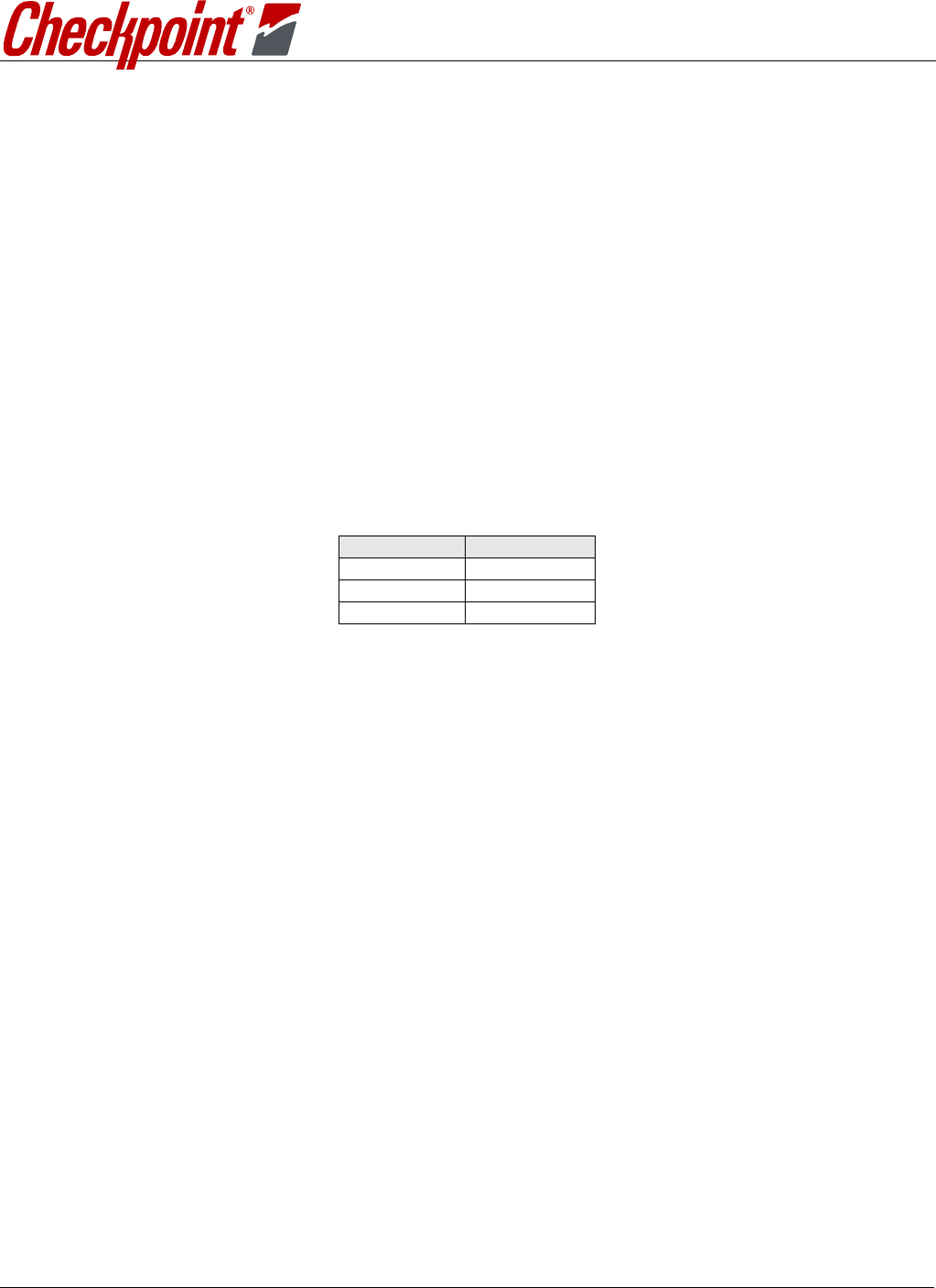
The pin assignments for the power connector are as follows:
PIN # SIGNAL
1 +24V RTN
2 GND
3 +24V
Table 1: Power Connector Pin Assignments
The input +24V is converted to +12V, +5V, +3.3V, +2.5V and +1.2V through DC-DC converters
integrated within the PCB circuitry. Both switch mode and linear regulators are used.
5.0 DEVICE LABELING
The TR7240 modules have been labeled with their own FCC ID number and if the FCC ID is not
visible when the module is installed inside another device, then the outside of the finished product
into which the module is installed must also display a label referring to the enclosed module. This
exterior label displays this following:
MODEL:PCB,TR7240 TX/RX W/COMM
S/N: 10059624XXXXXXXXXX
IC: 3356B-TR7240
-or-
Contains FCC ID: D04TR7420
This device complies with Part 15 of the FCC Rules.
Operation is subject to the following two conditions:
(1) this device may not cause harmful interference, and (2) this device must accept any
interference received, including interference that may cause undesired operation.

USER’S MANUAL, TR7240 TX/RX
CHECKPOINT SYSTEMS, INC. CONFIDENTIAL AND PROPRIETARY INFORMATION, FOR INTERNAL USE ONLY
Document No. Rev. 00 Page 8 of 10
6.0
12B
MAIN PCB CONNECTIONS (PERIPHERAL I/O)
The peripheral I/O will be used to control various peripheral devices. The table below lists the
connector number and their respective description. These connectors are located on the main
board.
CONNECTOR PIN # LABEL PIN DESCRIPTION FUNCTION
J2 1 TX1 A
2 TX1 Ground Pri. 2-Loop or PAB via coupler
3 TX1 B
J3 1 TX2 A
2 TX2 Ground Pri. 3-Loop or SAB via coupler
3 TX2 B
J9 1 Alg In Input Alarm Group
2 Alg Out Output
3 Gnd Ground
4 Gnd Ground External Alarm Group
5 Rly Alg+ Com. Dry Contact Output
6 Rly Alg- N.O. Dry Contact Output
J11 1 +24VDC
2 LTS2+ SAB Lights+ SAB Lights
3 LTS- PAB/SAB Lights Return
4 LTS+ PAB Lights+ PAB Lights
5 SND1- PAB Sound Return PAB Sounder
6 SND1+ PAB Sound+
J19 1 MP
Dry-Contact Input Metal Point
2 Dry-Contact Input
J18/J31 1 Ret +24VDC Return Pedestal Main Power
2 Gnd
3 +24v +24 VDC
J20/J22 1 Rx A RS485 A IPC
2 Rx B RS485 B
3 GND Ground
4 SYNC+ SYNC A SYNC
5 SYNC- SYNC B
6 GND Ground
7 Tx A RS485 A IPC
8 Tx B RS485 B
J41 1 RLY CNT+ Counter + External Counter
2 RLY CNT- Counter Ground Return
J54 1 +24VDC
2 LTS2+ SAB Lights+ SAB Lights
3 LTS- PAB/SAB Lights Return
4 LTS+ PAB Lights+ PAB Lights
5 SND2- SAB Sound Return SAB Sounder
6 SND2+ SAB Sound+
J39 1 LTS2+ SAB Lights+ SAB Lights
2 LTS+ PAB Lights+ PAB Lights
3 LTS- PAB/SAB Lights Return
4 SND1+ PAB Sound+ PAB Sounder
5 SND1- PAB Sound Return
6 +24VDC

USER’S MANUAL, TR7240 TX/RX
CHECKPOINT SYSTEMS, INC. CONFIDENTIAL AND PROPRIETARY INFORMATION, FOR INTERNAL USE ONLY
Document No. Rev. 00 Page 9 of 10
CONNECTOR PIN # LABEL PIN DESCRIPTION FUNCTION
J25 1 LTS+ PAB Lights+ PAB Lights
2 LTS2+ SAB Lights+ SAB Lights
3 LTS- PAB/SAB Lights Return
4 SND2+ SAB Sound+ SAB Sounder
5 SND2- SAB SoundReturn
6 +24VDC
J48
1 RS-232 RX Data Badge Board
2 RS-232 TX Data
3 Ground
4 BADGE Power (+3.3
Vdc
)
5 Ground
6 Local Alarm Disable Input
7 Pedestal Reset Input
8 Global Alarm Disable Input
Table 2: Main PCB Connections

USER’S MANUAL, TR7240 TX/RX
CHECKPOINT SYSTEMS, INC. CONFIDENTIAL AND PROPRIETARY INFORMATION, FOR INTERNAL USE ONLY
Document No. Rev. 00 Page 10 of 10
7.0 COMMUNICATIONS BOARD I/O
CONNECTOR PIN # LABEL PIN DESCRIPTION FUNCTION
J72 1 PEOPLE CTR RS-485 VisiPlus
2 GND
3 RS-485
4 +24VDC
J11 1 KEY1 Key Switch 1
2 KEY1
3 INTLK1 NC
4 NC
5 INTLK1- Deactivation Interlock 1
6 INTLK1+
J54 1 KEY2 Key Switch 2
2 KEY2
3 INTLK2 NC Sounder 2
4 NC
5 INTLK2- Deactivation Interlock 2
6 INTLK2+
J51 1 RS232 Rx
2 RS232 Tx Evolve Modem Communications
3 GND
4 +5VDC
5 MODEM GND
6 NC
7 RS232 CTS
8 RS232 RTS
J44 1 RLY1 NC External Relay 1
2 RLY1 NC
3 EXT RLY GND
4 RLY1 NO
5 RLY1 NO
6 GND
J45 1 RLY2 NC
2 RLY2 NC External Relay 2
3 EXT RLY GND
4 RLY2 NO
5 RLY2 NO
6 GND
J1 1 Ethernet
Table 3: Communications Board I/O