Checkpoint Systems WRTZ2000 UHF RFID Reader User Manual 10058016r00 Users Manual
Checkpoint Systems Inc UHF RFID Reader 10058016r00 Users Manual
Contents
- 1. Installation Manual
- 2. User Manual
User Manual

UHF-RFID READER WRTZ-2000
UHF-RFID Reader WRTZ-2000 User’s Manual
10058016
Last Updated: February 4, 2015
Revision 00
Checkpoint Systems International GmbH
Brentanostrasse 27-29
69434 Hirschhorn
(06272)928-0

UHF-RFID READER WRTZ-2000
Copyright © 2015 by Checkpoint Systems, Inc.
Released February 15
Published by:
Checkpoint Systems International GmbH.
Brentanostrasse 27-29
69434 Hirschhorn
Germany
UHF-RFID Reader WRTZ-2000 Users Manual
Part Number: 10078784
Trademarks
Checkpoint is a registered trademark of Checkpoint Systems, Inc.
Other product and company names herein may be trademarks of their respective owners.
Other products © or ® their respective manufacturers or copyright holders.
Copyright and Warranty Information
The information in this guide is subject to change without notice.
Because of the changing nature of this product information presented in the UHF-RFID Reader
WRTZ-2000 Users Manual, Checkpoint Systems, Inc. is not liable for any omissions, misstatements,
or other errors of information.
The information presented in the Users Manual may not be copied, used or disclosed to others for the
purpose of procurement or manufacturing without the written permission of Checkpoint Systems, Inc.
This guide and the products discussed in this guide are the exclusive property of Checkpoint Systems
Inc. Copyright laws of the United States protects all information and products.
Copyright© 2015 Checkpoint Systems, Inc. All rights reserved.

Checkpoint Systems Intern. GmbH Company Confidential
Last Updated: 2/9/2015 11:59 AM 3 of 16
Table of contents
1 REVISION CONTROL ...................................................................................... 4
1.1 REVISION HISTORY ....................................................................................... 4
2 BASIC SAFETY INFORMATION ........................................................................... 5
2.2 NOTE ABOUT THE DISPOSAL OF OLD UNITS ............................................................... 6
3 INTRODUCTION ........................................................................................... 7
3.1 INSTALLATION ........................................................................................... 8
4 TECHNICAL DATA ......................................................................................... 9
4.1 MECHANICAL DATA ...................................................................................... 9
4.2 FRONT VIEW ............................................................................................ 10
4.3 SIDE VIEW .............................................................................................. 10
4.4 REAR VIEW ............................................................................................. 10
4.5 READER SPECIFICATIONS ................................................................................ 11
4.6 ENVIRONMENT SPECIFICATIONS ......................................................................... 11
4.7 DIGITAL INPUT SPECIFICATION .......................................................................... 12
4.8 INTERPEDESTAL IN SPECIFICATION ...................................................................... 12
4.9 INTERPEDESTAL OUT SPECIFICATION ................................................................... 12
4.10 ETHERNET LAN SPECIFICATION ......................................................................... 13
4.11 RS-232 SPECIFICATIONS ................................................................................ 13
4.12 LAMP PED 1 SPECIFICATION ........................................................................... 14
4.13 LAMP CENTER SPECIFICATION ........................................................................ 14
4.14 LAMP PED 2 SPECIFICATION ........................................................................... 14
4.15 KEY SWITCH .......................................................................................... 14
4.16 BUZZER ................................................................................................ 14
5 ORDERING INFORMATION ............................................................................. 15
6 GLOSSARY ............................................................................................... 16
7 ANNEX DECLARATION OF CONFORMITY ............................................................ 16

Checkpoint Systems Intern. GmbH Company Confidential For Internal Use Only
Last Updated: 2/9/2015 11:59 AM 4 of 16
1 Revision Control
1.1 Revision History
Content changes to this document from its previous version to the current level are indicated by
Microsoft Word track changes bars (|) in the left margin of the document unless a complete rewrite
is indicated. Accept all tracked changes to the current document before updating it. This procedure
highlights the new changes made to the document by the author thus facilitating efficient review of
the document.
Revision
# Revision
Date Change Description and Explanation Created/Changed By
00 02/04/15 CR2648 Hans-Günter Meuthen

Checkpoint Systems Intern. GmbH Company Confidential For Internal Use Only
Last Updated:
2/9/2015 11:59 AM
5 of 16
2 Basic safety information
• Read these operating instructions before using the UHF-RFID READER WRTZ-
2000 for the first time! Make yourself completely familiar with the installation and
operation of the UHF-RFID READER WRTZ-2000! Retain these operating
instructions for later reference.
• The UHF-RFID READER WRTZ-2000 is used for contact less reading of RFID
(Radio Frequency Identification) Tags. Only use the UHF-RFID READER
WRTZ-2000 in the manner described in these operating instructions!
• Note all the detailed safety information given within the individual work steps.
All safety information in these operating instructions is identified with the warning
symbol shown here.
• Never use the UHF-RFID READER WRTZ-2000 in areas where there is a danger
of explosion.
• Note that the electric installation of the UHF-RFID READER WRTZ-2000 may
only be done by a professional.
• It is essential to comply with the electrical, mechanical and climatic specifications
given in the Technical Data section. For further information see Chapter Technical
data.
• Do not make any changes or modifications to the UHF-RFID READER
WRT2000. If changes or modifications are made, all guarantee claims are voided.
Furthermore, the radio approval required for its operation is void!
• Have a faulty UHF-RFID READER WRTZ-2000 inspected and repaired by our
repair center. Never make any repairs yourself under any circumstances.
• Dispose of the UHF-RFID READER WRTZ-2000 properly after taking out of
service. Never put the UHF-RFID READER WRTZ-2000 into the normal
household waste.
Federal Communications Commission (FCC) Approval Note:
This device complies with Part 15 of the FCC Rules and standard(s). Operation is subject to the following
two conditions: (1) this device may not cause harmful interference, and (2) this device must accept any
interference received, including interference that may cause undesired operation.
This equipment has been tested and found to comply with the limits for a Class A digital device, pursuant to
part 15 of the FCC Rules. These limits are designed to provide reasonable protection against harmful
interference when the equipment is operated in a commercial environment. This equipment generates, uses,
and can radiate radio frequency energy and, if not installed and used in accordance with the instruction
manual, may cause harmful interference to radio communications. Operation of this equipment in a
residential area is likely to cause harmful interference in which case the user will be required to correct the
interference at his own expense.
Changes or modifications not expressly approved by the party responsible for compliance could void the
user’s authority to operate the equipment.

Checkpoint Systems Intern. GmbH Company Confidential For Internal Use Only
Last Updated:
2/9/2015 11:59 AM
6 of 16
Industry Canada Approval Note:
This Class A digital apparatus complies with Canadian ICES-003.
Cet appareil numérique de la classe A est conforme à la norme NMB-003 du Canada.
This device complies with Industry Canada licence-exempt RSS standard(s). Operation is subject to the
following two conditions: (1) this device may not cause interference, and (2) this device must accept any
interference, including interference that may cause undesired operation of the device.
Le présent appareil est conforme aux CNR d'Industrie Canada applicables aux appareils radio exempts de
licence. L'exploitation est autorisée aux deux conditions suivantes : (1) l'appareil ne doit pas produire de
brouillage, et (2) l'utilisateur de l'appareil doit accepter tout brouillage radioélectrique subi, même si le
brouillage est susceptible d'en compromettre le fonctionnement.
2.2 Note about the disposal of old units
Within the member countries of the European Union In accordance with the European
Union guideline 2002/96/EC, Checkpoint Systems takes back old devices within the member countries
of the European Union and disposes of them in an appropriate way. The devices concerned by this are
marked with the symbol shown aside.
•
For further information on the return procedure, please contact your local sales
contact. You will find the addresses of all sales partners in the internet on
www.checkpointsystems.com. Please take into consideration also the national
implementation of the EU guideline 2002/96/EC of your country.
For all other countries
•
Dispose of the WRTZ-2000 properly after taking out of service.
•
Observe the regulations valid in your country for the disposal of electronic devices.
•
Never put the WRTZ-2000 into the normal household waste.
Checkpoint Systems Intern. GmbH
Last Updated:
2/9/2015 11:59 AM
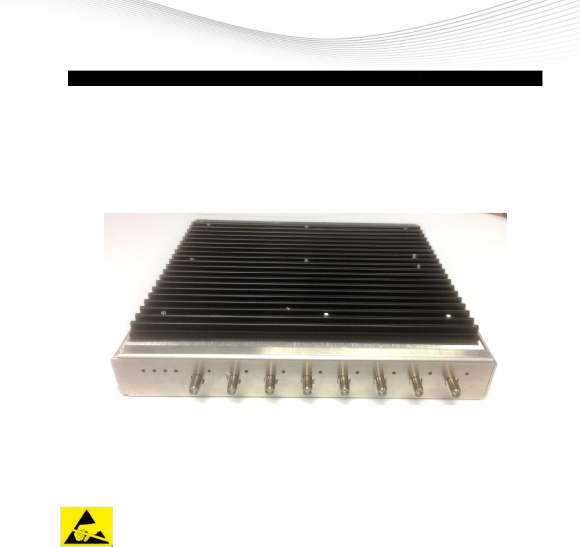
3 Introduction
UHF-RFID Reader
WRTZ
(UHF) radio frequency identification (RFID) system (typically called an interrogator or
reader) which communicates with targets that are applied to or incorporated
The targets (typically referred to as tags or labels) serve to identify the item to which it is
attached based on a unique ID stored on the target.
The UHF-
RFID READER
static discharge or other high voltage. Use proper Electrostatic Discharge (ESD) precautions
to avoid static discharge when handling or making connections to the
or communication ports. Equipment failure can result if the antenna o
are subjected to ESD.
Company Confidential
For Internal Use Only
7 of 16
WRTZ
-2000
is the electronics system of an Ultra High Frequency
(UHF) radio frequency identification (RFID) system (typically called an interrogator or
reader) which communicates with targets that are applied to or incorporated
The targets (typically referred to as tags or labels) serve to identify the item to which it is
attached based on a unique ID stored on the target.
ATTENTION
RFID READER
WRTZ-2000
antenna ports may be susceptible to damag
static discharge or other high voltage. Use proper Electrostatic Discharge (ESD) precautions
to avoid static discharge when handling or making connections to the
or communication ports. Equipment failure can result if the antenna o
are subjected to ESD.
For Internal Use Only
is the electronics system of an Ultra High Frequency
(UHF) radio frequency identification (RFID) system (typically called an interrogator or
reader) which communicates with targets that are applied to or incorporated
into an item.
The targets (typically referred to as tags or labels) serve to identify the item to which it is
antenna ports may be susceptible to damag
e from
static discharge or other high voltage. Use proper Electrostatic Discharge (ESD) precautions
to avoid static discharge when handling or making connections to the
WRTZ-1500 antenna
or communication ports. Equipment failure can result if the antenna o
r communication ports
Checkpoint Systems Intern. GmbH Company Confidential For Internal Use Only
Last Updated: 2/9/2015 11:59 AM 8 of 16
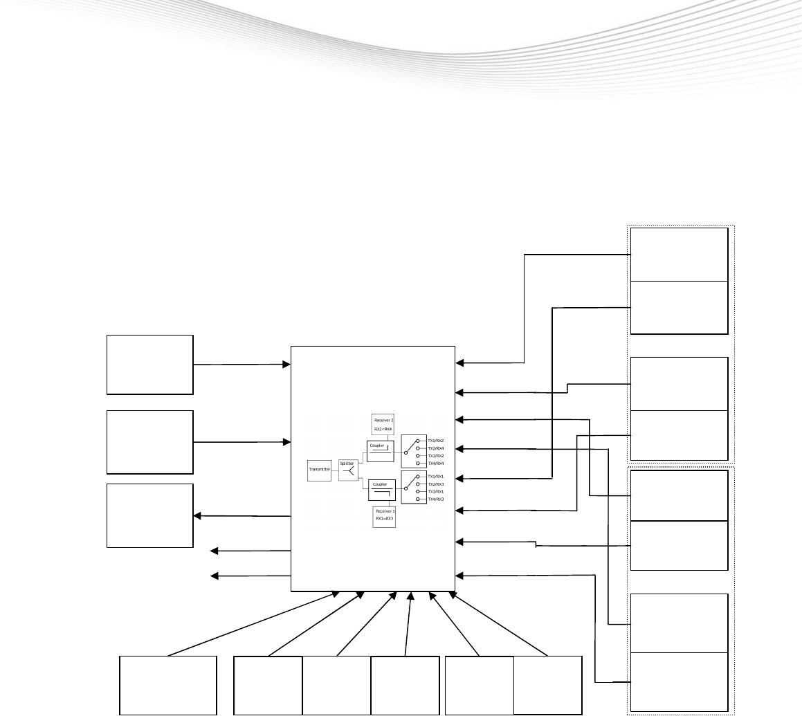
3.1 Installation
The UHF-RFID READER WRTZ-2000 is build in a Pedestal System, for the installation guidelines refer to
the User Manual 10034763 E10 RF-RFID Pedestal.
Block Diagram of Pedestal System with Dual Aisle.
WRTZ-2000
12V DC
TX1/RX1
ANTENNA
TX2/RX4
ANTENNA
TX2/RX3
ANTENNA
TX3/RX2
ANTENNA
AC/DC
ADAPTER
2 Digital
INPUT
Pedestal
left side
TX3/RX1
TX2/RX3
TX2/RX4
TX1/RX2
TX1/RX2
ANTENNA
TX3/RX1
ANTENNA
TX4/RX4
ANTENNA
TX3/RX2
TX4/RX4
TX4/RX3
TX1/RX1
TX4/RX3
ANTENNA
LAN
Pedestal
right side
Interped. IN
Interped.
OUT
LAMP
PED 1
LAMP
PED 2
LAMP
Center
Key
Switch
Extern
Buzzer
RS232
Aisle A
Aisle B

Checkpoint Systems Intern. GmbH Company Confidential For Internal Use Only
Last Updated: 2/9/2015 11:59 AM 9 of 16
4 Technical Data
4.1 Mechanical Data
Size : 8.2 x 8.7 x 1.5 in (208 x 221 x 38 mm)
Weight: 2.6 lbs (1.2 Kg)
Case material Aluminum
Connectors
Ethernet RJ45
Interpedestal IN Rj45
Interpedestal OUT RJ45
RS232 RJ45
DC-Input 3 pol
Digital IN Connector 4 pol
LAMP PED 1 2 pol
LAMP Center 2 pol
LAMP PED 2 2 pol
Key Switch 2 pol
Buzzer 2 pol
RF ANT 1-8 SMA
Checkpoint Systems Intern. GmbH Company Confidential For Internal Use Only
Last Updated: 2/9/2015 11:59 AM 10 of 16
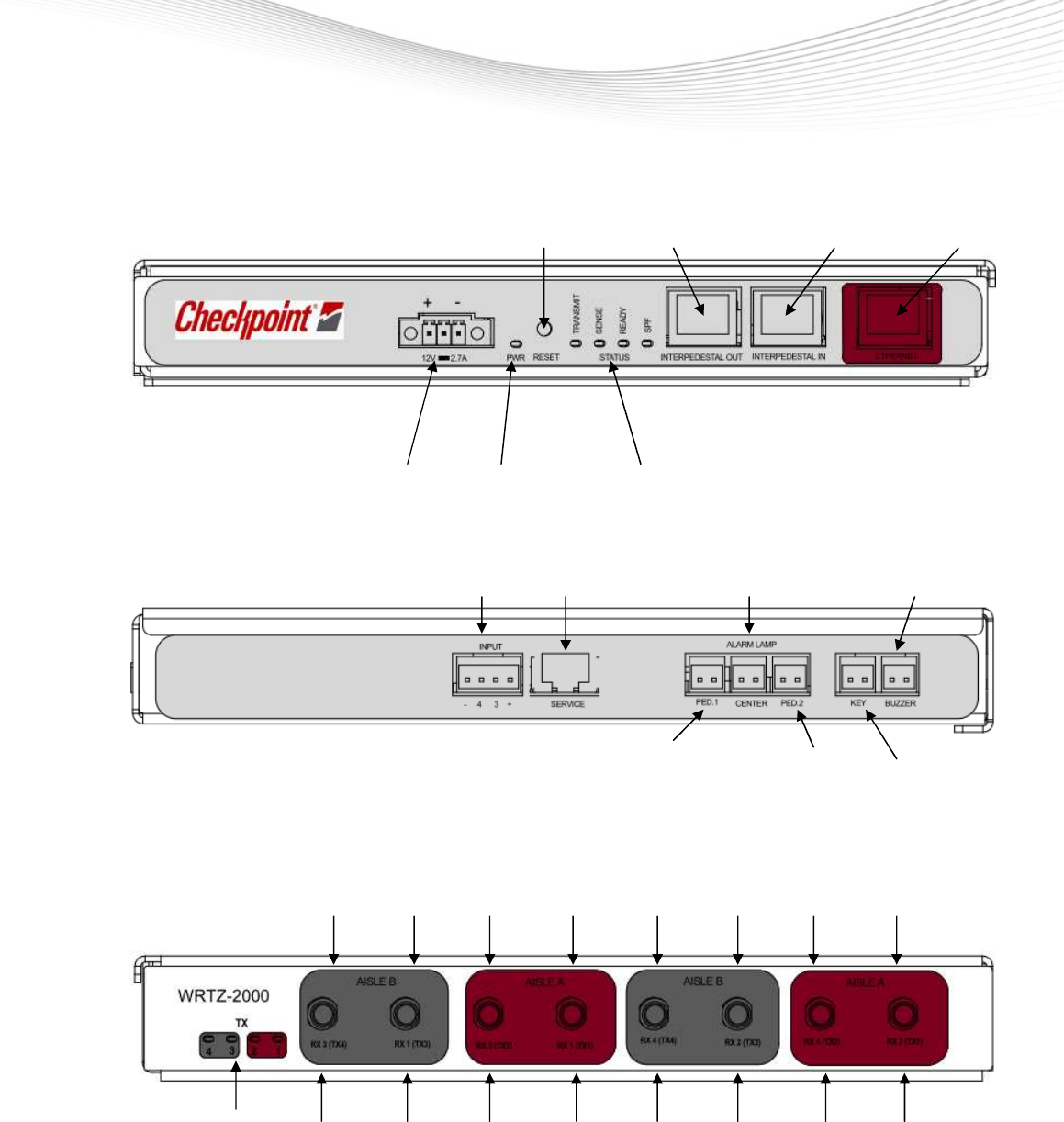
4.2 Front view
RESET
Button Interpedestal OUT Interpedestal IN LAN
DC Connector Power On LED Status LED’s
4.3 Side view
Digital Inputs RS-232 LAMP CENTER BUZZER
LAMP PED1 LAMP PED2 KEY SWITCH
4.4 Rear view
RX RX1 RX3 RX1 RX4 RX2 RX4 RX2
Status LED’s
TX4 TX3 TX2 TX1
TX4 TX3 TX2 TX1

Checkpoint Systems Intern. GmbH Company Confidential For Internal Use Only
Last Updated: 2/9/2015 11:59 AM 11 of 16
4.5 Reader Specifications
Power Connection
Input Voltage 10,2-13,8 Vdc
Input current 2.7 A at 12 Vdc
Power Consumption 12W ( typical while idle)
33 W ( typical at 0.5 W conducted RF output power and Lamps driving)
The WRTZ-2000 can be powered by suitable AC/DC-Adapter.
Usable Power Supply’s
- LFZVC60NP12E4, Part Number: 7284242
- AEB70US12, Part Number: 7421850
WRTZ-2000 does not have power switch. If it is necessary to switch off power, simply unplug 12V DC
connector.
RF Connection
RX/TX Antenna Ports 8 SMA connectors, TX power is halved by internal power splitter
and distributed by internal switches to TX1, TX2, TX3, TX4
Impedance 50 Ohm
Frequency Range 865-868 MHz 902-928 MHz
TX RF Output Power 10mW – 0.5 W conducted (10 - 27 dBm)
RX RF Input Power 100mW max. (20 dBm)
Caution: This device has been designed to operate with no more than 1 Watt into the antenna and an
antenna gain of no more than 6 dBic. Antenna having a higher gain is strictly prohibited per
regulations of Industry Canada, unless power into the antenna is decreased to compensate
for the increased antenna gain. The required antenna impedance is 50 ohms.
To reduce potential radio interference to other users, the antenna type and its gain should be
so chosen that the equivalent isotropic radiated power (EIRP) is not more than that required
for successful communication.
The installer of this radio equipment must ensure that the antenna is located or pointed such
that it does not emit an RF field in excess of Health Canada limits for the general
population; consult Safety Code 6, obtainable from Health Canada’s website at
www.hc-sc.gc.ca
4.6 Environment Specifications
Operating temperature 32
°
F to 131
°
F ( 0
°
C to 55
°
C )
Storage temperature - 40
°
F to 185
°
F ( -40
°
C to 85
°
C )
Relative Humidity 5% to 95 % non-condensing

Checkpoint Systems Intern. GmbH Company Confidential For Internal Use Only
Last Updated: 2/9/2015 11:59 AM 12 of 16
4.7 Digital Input Specification
Connector RIACON Part Number: 31182104 (1x4)
Input 12 Vdc, 10 mA, Optically Isolated
Signals
Pin 1 -- +12V
Pin 2 – D_IN3 (Digital Input 3)
Pin 3 – D_IN4 (Digital Input 4)
Pin 4 -- GND
4.8 Interpedestal IN Specification
Connector RJ-45
Ethernet 10/100 BaseT
Indicators Yellow - Indicates link is operational
Green - Indicates network traffic detected.
Signals
Pin 1 – TXD+ (Transmit Data +)
Pin 2 – TXD- (Transmit Data -)
Pin 3 – RXD+ (Receive Data +)
Pin 4 – LAMP1_DRIVE
Pin 5 – LAMP2_INCOME
Pin 6 – RXD- (Receive Data -)
Pin 7 – GND
Pin 8 – SYNC_IN (optically isolated)
4.9 Interpedestal OUT Specification
Connector RJ-45
Ethernet 10/100 BaseT
Indicators Yellow - Indicates link is operational
Green - Indicates network traffic detected.
Signals
Pin 1 – TXD+ (Transmit Data +)
Pin 2 – TXD- (Transmit Data -)
Pin 3 – RXD+ (Receive Data +)
Pin 4 – LAMP1_INCOME
Pin 5 – LAMP2_DRIVE
Pin 6 – RXD- (Receive Data -)
Pin 7 – GND
Pin 8 – SYNC_OUT +12V, 10mA

Checkpoint Systems Intern. GmbH Company Confidential For Internal Use Only
Last Updated: 2/9/2015 11:59 AM 13 of 16
4.10 Ethernet LAN Specification
Connector RJ-45
Ethernet 10/100 BaseT
Indicators Yellow - Indicates link is operational
Green - Indicates network traffic detected.
Signals
Pin 1 – TXD+ (Transmit Data +)
Pin 2 – TXD- (Transmit Data -)
Pin 3 – RXD+ (Receive Data +)
Pin 4 – Termination
Pin 5 – Termination
Pin 6 – RXD- (Receive Data -)
Pin 7 – Termination
Pin 8 – Termination
4.11 RS-232 Specifications
Connector RJ45
Baud rate 600 - 115200 (Default = 115200)
Parity None
Data bits 8
Stop bits 1
Signals
Pin 1 TXD Processor
Pin 2 RXD Processor
Pin 3 GND
Pin 4 NC
Pin 5 GND
Pin 6 NC
Pin 7 TXD FPGA
Pin 8 RXD FPGA

Checkpoint Systems Intern. GmbH Company Confidential For Internal Use Only
Last Updated: 2/9/2015 11:59 AM 14 of 16
4.12 LAMP PED 1 Specification
Connector RIACON Part Number: 31182102 (1x2)
Signals
Pin 1 +11V/200mA
Pin 2 GND
4.13 LAMP CENTER Specification
Connector RIACON Part Number: 31182102 (1x2)
Signals
Pin 1 +11V/200mA
Pin 2 GND
4.14 LAMP PED 2 Specification
Connector RIACON Part Number: 31182102 (1x2)
Signals
Pin 1 +11V/200mA
Pin 2 GND
4.15 KEY SWITCH
Connector RIACON Part Number: 31182102 (1x2)
Signals
Pin 1 switch contact
Pin 2 switch contact
4.16 Buzzer
Connector RIACON Part Number: 31182102 (1x2)
Signals
Pin 1 +12V/10mA
Pin 2 GND

Checkpoint Systems Intern. GmbH Company Confidential For Internal Use Only
Last Updated: 2/9/2015 11:59 AM 15 of 16
5 Ordering Information
The UHF-RFID Reader is available with the following number
Order Number: 70034075 WRTZ-2000

Checkpoint Systems Intern. GmbH Company Confidential For Internal Use Only
Last Updated: 2/9/2015 11:59 AM 16 of 16
6 Glossary
RFID
Radio Frequency Identification.
EPC
Electronic Product Code, a unique item identification number
EPC Global
A new global standard that combines RFID technology, existing communications network
infrastructure and the Electronic Product Code to enable immediate and automatic
identification and tracking of an item through the whole supply chain globally, resulting in
improved efficiency and visibility of the supply chain.
7 Annex Declaration of Conformity
EMC limits and radio approvals
EMV for Short Range Device ETSI EN 301 489-3
Safety of equipment of low voltage device EN 60950-1
Approval for Short Range Device; Europe ETSI EN 302 208
Approval for Short Range Device; USA FCC 47 CFR Part 15
Approval for Short Range Device; Canada RSS 210 Issue 8