Chengdu Ebyte Electronic Technology E30 Wireless transceiver module User Manual
Chengdu Ebyte Electronic Technology Co., Ltd. Wireless transceiver module Users Manual
User manual

E30(915T20S)-User Manual-V1.0 Website: www.cdebyte.com/en
Page 1 of 8 Technical Support : support@cdebyte.com
E30(915T20S)-User Manual-V1.0
Contents
1. Introduction................................................................................................................ 2
1.1 Feature............................................................................................................... 2
1.2 Electrical Parameters......................................................................................... 2
2. UART functional description (default).......................................................................4
2.1 Fixed transmission.............................................................................................4
2.2 Broadcast transmission......................................................................................4
2.3 Broadcast address.............................................................................................. 4
2.4 Monitoring address............................................................................................4
3. Functional description................................................................................................ 5
3.1 Pin definition..................................................................................................... 5
3.2 Connect to MCU............................................................................................... 6
3.3 Reset.................................................................................................................. 6
3.4 AUX description................................................................................................6
4. Customization.............................................................................................................8
5. About us......................................................................................................................8

E30(915T20S)-User Manual-V1.0 Website: www.cdebyte.com/en
Page 2 of 8 Technical Support : support@cdebyte.com
1. Introduction
1.1 Feature
E30(915T20S) is a 100mW wireless transceiver module(UART), half-duplex& transparent transmission, which
operates at 907~922.5MHz(default: 915MHz), TTL Level, compatible with the 3.3V and 5V IO port.
The module has the function of data encryption & compression. The data of the module transmitted over
the air features randomness. And with the rigorous encryption & decryption, data interception becomes
pointless. The function of data compression can decrease the transmission time & probability of being
interfered, while improving the reliability & transmission efficiency.
No.
Usage
Description
1
Ultra-low
power
consumption
It supports WOR to reduce overall power consumption. In power-saving
mode(Mode 2), it can regulate overall power consumption by setting receiving
response delay; The maximum receiving response delay can be configured as
2000ms, and the average current is about 30uA.
2
Fixed
transmission
Module can communicate with other modules which work in different channels
and addresses, it is easy for networking and repeater.
For example: module A transmits AA BB CC to module B (address: 0x00 01,
channel: 0x80), HEX format is 00 01 80 AA BB CC (00 01 refers to the address of
module B, 80 refers to the channel of module B), then module B receives AA BB
CC (only module B).
3
Broadcast
transmission
Set the module address as 0xFFFF, then the module can communicate with other
modules in same channel.
4
FEC
Forward Error Correction, high coding efficiency & good correction
performance.
In the case of sudden interference, it can correct the interfered data packets
proactively, so that the reliability & transmission range are improved
correspondingly. Without FEC, those data packets can only be dropped.
5
Sleep mode
When the module works in sleep mode (mode 3), transmitting & receiving is not
available, while the configuration is available. The typical current is 5.0uA in this
mode.
6
Application
With better capability of penetration and diffraction than 2.4G, E30(915T20S) is
suitable for the open environment with few obstacles.
1.2 Electrical Parameters
No.
Parameter item
Parameter details
Description
1
Size
17 * 30mm
-
2
Weight
2.3g
Average weight
3
Frequency Band
907~922.5MHz Default: 915MHz, channel:16
4
Process
Lead-free, SMT
To ensure the consistency and reliability
5
Connector
11PIN-2.0mm
SMD
6
Supply voltage
2.1 ~ 5.5V DC
Note: the voltage higher than 5.5V is forbidden

E30(915T20S)-User Manual-V1.0 Website: www.cdebyte.com/en
Page 3 of 8 Technical Support : support@cdebyte.com
7
Communication
level
Maximum 5.2V
The difference with supply voltage should be less
than 0.3V to reduce power consumption
8
Operation Range
2000m
Clear and open area, 20dBm, antenna gain: 2dBi,
height: 2m,air data rate: 1kbps
9
Transmitting power
20dBm
Four optional level: 20, 17, 14, 10dBm
10
Air data rate
1kbps
Eight optional level: 1, 2, 5, 8, 10, 15, 20, 25kbps
11
Standby current
5.0uA
M1=1, M0=1 ( Mode 3 )
12
Transmitting current
89mA@20dBm
The proposed power supply current is not less than
200mA
13
Receiving current
16mA
Mode 0 or 1
14
Communication
interface
UART
8N1, 8E1, 8O1,eight kinds of UART baud rate, from
1200 to 115200 bps(Default: 9600)
15
Driving mode
UART
Can be configured to push-pull/high pull,
open-drain
16
Transmitting length
512 bytes buffer
58 bytes per package
17
Receiving length
512 bytes buffer
58 bytes per package
18
Address
65536
Easy for network, broadcast and fixed transmission
19
WOR
Available
Minimum average power consumption is about
30uA (applicable for battery powered applications)
20
Antenna type
Stamp hole
IPX+stamp hole+spring antenna to lead out, 50Ω
characteristic impedance
21
Operating
temperature
-40 ~ +85℃
-
22
Operating humidity
10% ~ 90%
Relative humidity, no condensation
23
Storage
temperature
-40 ~ +125℃
-
24
Sensitivity
-138dBm@0.3kbps
Sensitivity has nothing to do with baud rate or timing
E30(915T20S)-User Manual-V1.0 Website: www.cdebyte.com/en
Page 4 of 8 Technical Support : support@cdebyte.com
2. UART functional description (default)
2.1 Fixed transmission
Hex
Description
The format: Hexadecimal, such as:00 03 04 AA BB CC
00 03 is the address of receiving module;04 is the channel ;AA BB CC is the transmission data。
Transmitting module A
Hexadecimal
Address:00 01;Channel 02
Receiving module B
Hexadecimal
Address:00 03;Channel 04
Receiving module C
Hexadecimal
Address:00 05;Channel 04
Receiving module D
Hexadecimal
Address:00 07;Channel 06
Module A must be in fixed mode.
Module A Transmitting data
Hexadecimal
00 03 04 AA BB CC
Module B receiving data
Hexadecimal
AA BB CC
Module C receiving data
Hexadecimal
No
Module D receiving data
Hexadecimal
No
Only the modules with matched address and channel can receive the data.
In fixed transmission, modules only support 1 packet length (pls refer to electrical parameters). If the data
packets exceed, then it need to be subcontracted automatically.
2.2 Broadcast transmission
Hex
Description
The format: Hexadecimal, such as:FF FF 04 AA BB CC
FF FF is the address;04 is the channel of receiving module;AA BB CC is the transmission data。
Transmitting module A
Hexadecimal
Address:00 01;Channel : 02
Receiving module B
Hexadecimal
Address:00 03;Channel 04
Receiving module C
Hexadecimal
Address:00 05;Channel 04
Receiving module D
Hexadecimal
Address:00 07;Channel 06
Module A must be in fixed mode.
Module A Transmitting data
Hexadecimal
FF FF 04 AA BB CC
Module B receiving data
Hexadecimal
AA BB CC
Module C receiving data
Hexadecimal
AA BB CC
Module D receiving data
Hexadecimal
No
All the module with this channel can receive the data.
In fixed transmission, modules only support 1 packet length (pls refer to electrical parameters). If the data
packets exceed, then it need to be subcontracted automatically.
2.3 Broadcast address
1. For example, set the address of module A as 0xFF FF, and the channel as 0x04.
2. When module A works as the transmitter (transparent transmission), all the receiving module with the
channel 0x04 can receive the data, so as to realize the broadcast.
2.4 Monitoring address
1. For example, set the address of module A as 0xFF FF, and the channel as 0x04.
2.When module A works as the receiver, all the receiving module with the channel 0x04 can receive the
E30(915T20S)-User Manual-V1.0 Website: www.cdebyte.com/en
Page 5 of 8 Technical Support : support@cdebyte.com
data, so as to realize the monitoring.
3. Functional description
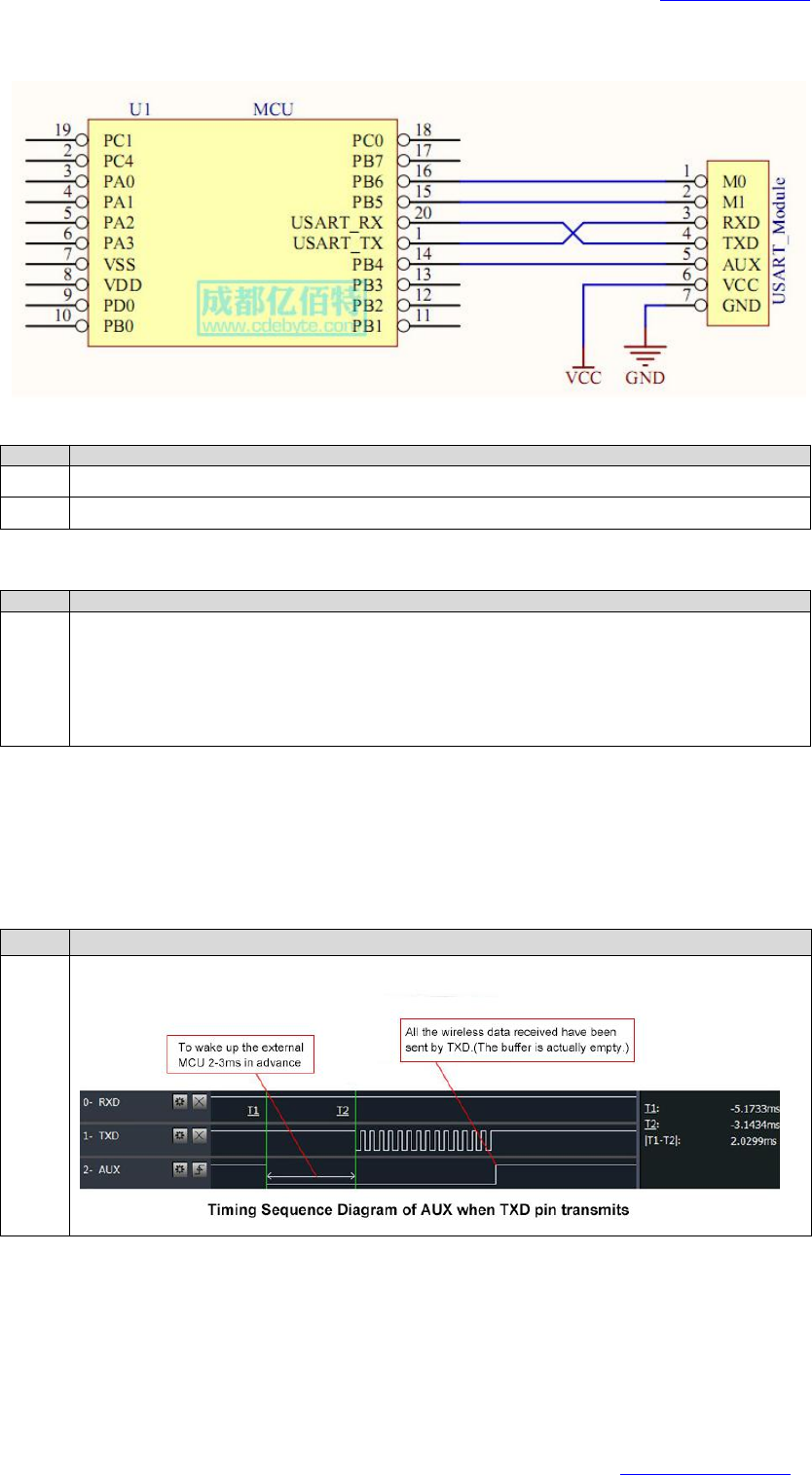
3.1 Pin definition
Pin No.
Pin item
Pin direction
Pin application
1
M0
Input
(weak pull-up)
Work with M1 & decide the four operating modes.
Floating is not allowed, can be ground.
2
M1
Input
(weak pull-up)
Work with M0 & decide the four operating modes.
Floating is not allowed, can be ground.
3
RXD
Input
TTL UART inputs, connects to external (MCU, PC) TXD
output pin. Can be configured as open-drain or pull-up
input.
4
TXD
Output
TTL UART outputs, connects to external RXD (MCU, PC)
input pin. Can be configured as open-drain or push-pull
output
5
AUX
Output
To indicate module ’ s working status & wakes up the
external MCU. During the procedure of self-check
initialization, the pin outputs low level. Can be configured
as open-drain output or push-pull output (floating is
allowed).
6
VCC
Power supply 2.1V~5.5V DC
7
GND
Ground
8
ANT
Antenna
9
GND
Ground
10
GND
Ground
11
GND
Ground
E30(915T20S)-User Manual-V1.0 Website: www.cdebyte.com/en
Page 6 of 8 Technical Support : support@cdebyte.com
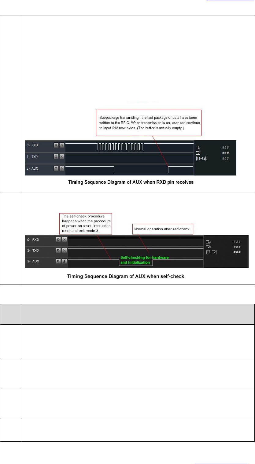
3.2 Connect to MCU
No.
Description ( STM8L MCU )
1
The UART module is TTL level.
2
For some MCU works at 5VDC, it may need to add 4-10K pull-up resistor for the TXD & AUX pin.
3.3 Reset
No.
Description
1
When the module is powered, AUX outputs low level immediately, conducts hardware self-check
and sets the operating mode on the basis of the user parameters. During the process, the AUX
keeps low level. After the process completed, the AUX outputs high level and starts to work as per
the operating mode combined by M1 and M0. Therefore, the user needs to wait the AUX rising
edge as the starting point of module’s normal work.
3.4 AUX description
AUX Pin can be used as indication for wireless send & receive buffer and self-check. It can indicate
whether there are data that are yet to send via wireless way, or whether all wireless data has been sent
through UART, or whether the module is still in the process of self-check initialization.
No.
Description
1
【Indication of UART output】can be used to wake up external MCU.
E30(915T20S)-User Manual-V1.0 Website: www.cdebyte.com/en
Page 7 of 8 Technical Support : support@cdebyte.com
2
【Indication of wireless transmitting】
Buffer (empty): the internal 512 bytes data in the buffer are written to the RFIC (Auto
subpackage). When AUX=1, the user can input data less than 512 bytes continuously without
overflow.
Buffer (not empty): when AUX=0, the internal 512 bytes data in the buffer have not been written
to the RFIC completely. If the user starts to transmit data at this circumstance, it may cause
overtime when the module is waiting for the user data, or transmitting wireless subpackage.
Notes: When AUX = 1, it does not mean that all the UART data of the module have been
transmitted already, perhaps the last packet of data is still in transmission.
3
【Configuration procedure of module】
Only happened when power-on resetting or exiting sleep mode.
No.
Notes for AUX
1
For function 1 & function 2 mentioned above, the priority should be given to the one with low
level output, which means if it meets each of any low level output condition, AUX outputs low
level, if none of the low level condition is met, AUX outputs high level.
2
When AUX outputs low level, it means the module is busy & cannot conduct operating mode
checking.
Within 1ms since AUX outputs high level, the mode switch will be completed.
3
After switching to new operating mode, it won’t be work in the new mode immediately until AUX
rising edge 2ms later.
If AUX is on the high level, the operating mode switch can be effected immediately.
4
When the user switches to other operating modes from mode 3 (sleep mode) or it’s still in reset
process, the module will reset user parameters, during which AUX outputs low level.

E30(915T20S)-User Manual-V1.0 Website: www.cdebyte.com/en
Page 8 of 8 Technical Support : support@cdebyte.com
4. Customization
★Please contact us for customization.
★Ebyte has established profound cooperation with various well-known enterprises.
5. About us
Chengdu Ebyte Electronic Technology Co., Ltd. (Ebyte) is specialized in wireless solutions and products.
◆We research and develop various products with diversified firmware;
◆Our catalogue covers WiFi, Bluetooth, Zigbee, PKE, wireless data transceivers & etc.;
◆With about one hundred staffs, we have won tens of thousands customers and sold millions of products;
◆Our products are being applied in over 30 countries and regions globally;
◆We have obtained ISO9001 QMS and ISO14001 EMS certifications;
◆We have obtained various of patents and software copyrights, and have acquired FCC, CE, RoHs & etc.
FCC Statement
This device complies with part 15 of the FCC Rules. Operation is subject to the
following two conditions: (1) This device may not cause harmful interference, and (2)
this device must accept any interference received, including interference that may cause
undesired operation.
Any Changes or modifications not expressly approved by the party responsible for
compliance could void the user's authority to operate the equipment.
The modular can be installed or integrated in mobile or fix devices only. This modular
cannot be installed in any portable device .
FCC Radiation Exposure Statement
This modular complies with FCC RF radiation exposure limits set forth for an
uncontrolled environment. This transmitter must not be co-located or operating in
conjunction with any other antenna or transmitter. This modular must be installed and
operated with a minimum distance of 20 cm between the radiator and user body.
If the FCC identification number is not visible when the module is installed inside
another device, then the outside of the device into which the module is installed must
also display a label referring to the enclosed module. This exterior label can use wording
such as the following: “Contains Transmitter Module FCC ID: 2ALPH-E30 Or
Contains FCC ID: 2ALPH-E30”
When the module is installed inside another device, the user manual of the host must
contain below warning statements;
1. This device complies with Part 15 of the FCC Rules. Operation is subject to the
following two conditions:
(1) This device may not cause harmful interference.
(2) This device must accept any interference received, including interference that may
cause undesired operation.
2. Changes or modifications not expressly approved by the party responsible for
compliance could void the user's authority to operate the equipment.
The devices must be installed and used in strict accordance with the manufacturer's
instructions as described in the user documentation that comes with the product.