Chengdu Vantron Technology AV5-AV7 Vending machine payment terminal User Manual 2
Chengdu Vantron Technology, Ltd. Vending machine payment terminal 2
Contents
- 1. User Manual 1
- 2. User Manual 2
- 3. user manual 1
- 4. user manual 2
user manual 2
AV 7 User’s
Manual
(Hardware)
Chengdu Vantron Technology Ltd. Co.
AV 7 User’s Manual (HW)

All rights reserved Page 2, Total 13
Revision record
Date Version Change Description
2013-1-12 1.1 Initial Version
AV 7 User’s Manual (HW)

All rights reserved Page 3, Total 13
Table of Contents
1FOREWORD..........................................................................................................................................4
1.1COPYRIGHTNOTICE......................................................................................................................................4
1.2NOTES.......................................................................................................................................................4
1.3STATEMENT................................................................................................................................................4
1.4DISCLAIMER................................................................................................................................................4
1.5LIMITATIONOFLIABILITY/NON‐WARRANTY.......................................................................................................4
1.6SAFETYINSTRUCTIONS..................................................................................................................................5
1.7PRECAUTIONS.............................................................................................................................................5
1.8SAFETYINSTRUCTIONSFORPOWERCABLESANDACCESSORIES.............................................................................5
2OVERVIEW...........................................................................................................................................7
2.1INTRODUCTION...........................................................................................................................................7
3POS‐AV7HARDWAREINSTRUCTIONS....................................................................................................8
3.1INTRODUCTIONOFAV 7...............................................................................................................................8
3.2BACKSIDEVIEWOFAV 7..............................................................................................................................8
4HARDWAREDESCRIPTION....................................................................................................................9
4.1IDENTIFY CONNECTOR.............................................................................................................................9
4.1.1Positionofconnector......................................................................................................................9
4.1.2Confirmthepindirection................................................................................................................9
4.2CONNECTORSDESCRIPTION...........................................................................................................................9
4.2.1PowerandUartinterface..............................................................................................................10
4.2.2Usbtype‐Ainterface.....................................................................................................................10
4.2.3RFconnectorfor3G......................................................................................................................11
4.3HARDWAREOPERATIONNOTES....................................................................................................................11
5TIPS....................................................................................................................................................12
AV 7 User’s Manual (HW)
All rights reserved Page 4, Total 13
1 Foreword
1.1 Copyright Notice
While all information contained herein have been carefully checked to assure its accuracy in
technical details and printing, Vantron assumes no responsibility resulting from any error or features
of this manual, or from improper uses of this manual or the software. Please contact our technical
department for relevant operation solutions if there is any problem that cannot be solved according to
this manual.
Vantron reserves all rights of this manual, including the right to change the content, form, product
features, and specifications contained herein at any time without prior notice. The latest version of
this manual is at www.vantrontech.com.cn. Please contact Vantron for further information:
Vantron Technology(Vantron)
E-mail: sales@vantrontech.com
The trademarks and registered trademarks in this manual are properties of their respective owners.
No part of this manual may be copied, reproduced, translated or sold. No changes or other purposes
are permitted without the prior written consent of Vantron.
Vantron reserves the right of all publicly-released copies of this manual.
1.2 Notes
Applicable notes are listed in the following table:
Sign Notice
Type Description
Notice Important information and regulations
Caution Caution for latent damage to system or
harm to personnel
1.3 Statement
It is recommended to read and comply with this manual before operating board, which provides
important guidance and helps decreasing the danger of injury, electric shock, fire, or any damage to
the device.
1.4 Disclaimer
Vantron assumes no legal liability of accidents resulting from failure of conforming to the safety
instructions.
1.5 Limitation of Liability/Non-warranty
AV 7 User’s Manual (HW)

All rights reserved Page 5, Total 13
For direct or indirect damage to this device or other devices of Vantron caused by failure of
conforming to this manual or the safety instructions on device label, Vantron assumes neither
warranty nor legal liability even if the device is still under warranty.
1.6 Safety Instructions
Keep and comply with all operation instructions, warnings, and information.
Pay attention to warnings on this device.
Read the following precautions so as to decrease the danger of injury, electric shock, fire, or any
damage to the device.
1.7 Precautions
Pay attention to the product labels/safety instructions printed on silk screens.
Do not try repairing this product unless declared in this manual.
Keep away from heat source, such as heater, heat dissipater, or engine casing.
Do not insert other items into the slot (if any) of this device.
• Keep the ventilation slot ventilated for cooling.
•System fault may arise if other items are inserted into this device.
Installation: ensure correct installation according to instructions from the manufacturer with
recommended installation tools.
Ensure ventilation and smoothness according to relevant ventilation standard.
1.8 Safety Instructions for Power Cables and Accessories
Proper power source only
Start only with power source that satisfies voltage label and the voltage necessary according to this
manual. Please contact technical support personnel of Vantron for any uncertainty about the
requirements of necessary power source.
Use tested power source
This product still contains a button lithium battery as a real-time clock after its external power source
is removed and therefore should not be short-circuited during transportation or placed under high
temperature.
Place cables properly:
Do not place cables at any place with extrusion danger.
Cleaning Instructions
AV 7 User’s Manual (HW)

All rights reserved Page 6, Total 13
Please power off before cleaning the device.
Do not use spray detergent.
Clean with a damp cloth.
Do not try cleaning exposed electronic components unless with a dust collector.
Support for special fault: Power off and contact technical support personnel of Vantron in case of
the following faults:
¾The device is damaged.
¾The temperature is excessively high.
¾Fault is still not solved after the operation according to the manual.
AV 7 User’s Manual (HW)

All rights reserved Page 7, Total 13
2 Over View
2.1 Introduction
Vantron offers both ARM and ATOM based Single Boards Computer (SBC) platforms
including Cirrus Logic EP9315, Marvell PXA255, PXA270, and PXA320, Intel IXP465, FreeScale
iMX31, Imx53,iMX6, Samsung S3C6410, TI OMAP35xx CortexA8 series, and Intel ATOM Z510
and Z530 processor boards. In additional to offering the standard SBCs, we also provide
professional customization board design services. Our seamless project management, efficient
error-free development process, strong fundamentals in technology, sufficient in human
resources, and on-time delivery will guarantee the success in your project development.
Based on idea of “Application Ready” products and services, our embedded computers have
embedded basic operation system which includes the drivers of its interfaces. So it is easy to be
used by adding your application software only. It can speed Time to Market of your products, and
saving more cost.
AV 7 is an A9 processor based board. The CPU is Freescale IMX6S,1GHz,Low Power
Processor. It has pin out most of the extended bus, peripherals, GPIOs, and others. It is easy to
customize connector board to meet different usage.
AV 7 User’s Manual (HW)

All rights reserved Page 8, Total 13
3 AV 7 Hardware Instructions
3.1 Introduction of AV 7
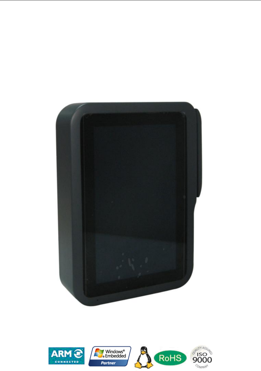
AV 7 is a POS system that is Retro-fit onto vending machine.It supports two kind of ways
for payment.The first one is paying by the credit card,there is a magcard reader on the side of
the machine.Another is paying by the electronic devices which has the NFC function.It is
installed on the front surface of the vending machine.
AV 7 User’s Manual (HW)
All rights reserved Page 9, Total 13
4 Hardware Description
This chapter describe the hardware Features include, switch, jumper, connector and PIN
function
The interface description ought to consult the connector sketch map. And attach
necessary message such as picture. Indicate the figure, PIN1 and match jack
4.1 Identify connector
This section describe how to find the position of connector and PIN1 on AV 7
single computer board.
4.1.1 Position of connector
As Figure 4.2show the main part and connector position of AV 7.
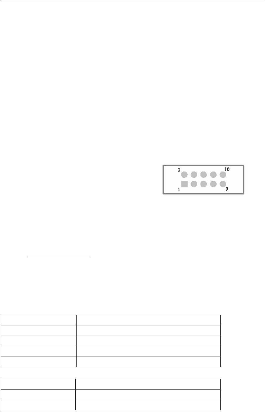
4.1.2 Confirm the pin direction
there is the pin number order in all Vantron’s
product, this picture at right indicate each pin’s
number, that message as show on the top
side(component side) of main board. on double row
connector, one side is naming odd number and another
side is naming even number. Please according to below method to confirm the Pin1 of
connector and jumper:
1. Usually, there is any number and mark at side of connector in main board, such as
trigonal mark, dot and number “1” all indicate the pin1 of connector
2. About the hole connector, you can see pin number on the reversed side
3. Download the AV 7 mechanism from Vantron technology sustain or Vantron net
site: www.vantrontech.com
4.2 Connectors Description
This table is the respective describe valid signal of connector on AV 7 board.
Figure type:
N/C Not connect
GND Ground
/ active low signal
+ Positive of difference signal
- negative of difference signal
Signal type:
I Input
O Output
IO input/output
AV 7 User’s Manual (HW)
All rights reserved Page 10, Total 13
P Power or ground
A Analog
OD Open drain
4.2.1 Power and Uart interface
HDR,1X10,Thru,3.81mm (PHOENIX: MCV 1.5/10-GF-3.81)
Pin Name Type Description
1 MDB_34V P Input power(11-60V)
2 GND_34 P External ground
3 MRX1 IO Data receive of MCU(Isolated)
4 MTX1 IO Data transmit of MCU(Isolated)
5 MDB_COMMON P Isolated ground
6 DEX_T IO Data transmit of MCU(RS232)
7 DEX_R IO Data receive of MCU(RS232)
8 TXD_DEX_3V IO Data transmit of MCU(TTL)
9 RX_TTL IO Data receive of MCU(TTL)
10 GND P Ground
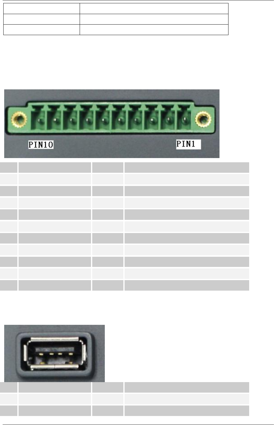
4.2.2 Usb type-A interface
CONN,USB Type A,4 Pos,Vert (KYCON: KUSBVX-AS-1-N-WHT)
Pin Name Type Description
1 USB_P O Usb power +5V
2 USBH1- P Usb date-
AV 7 User’s Manual (HW)
All rights reserved Page 11, Total 13
3 USBH1+ I Usb data+
4 USB_G P Ground
4.3 Hardware Operation Notes
a. Power prepare: Please confirm the power input is 12V. And the reference current is 1A. Make sure
the power input positive is not reversed.
b. Environment: For the assembled or debug platform, be sure there hasn’t any risk of circuit shortness
for the board. And make sure the anti static is done well.
c. Debug message view: Using COM port on P3 (COM1) to view the debug message. It will show the
boot message. In PC side, communication hyper terminal or other serial software tools can be used.
The debug port setting is: baud rate 115,200bps, NO hardware control, no ODD/EVEN checking, 1
Stop bit. Suggest use a cross cable, in two Female header.
AV 7 User’s Manual (HW)
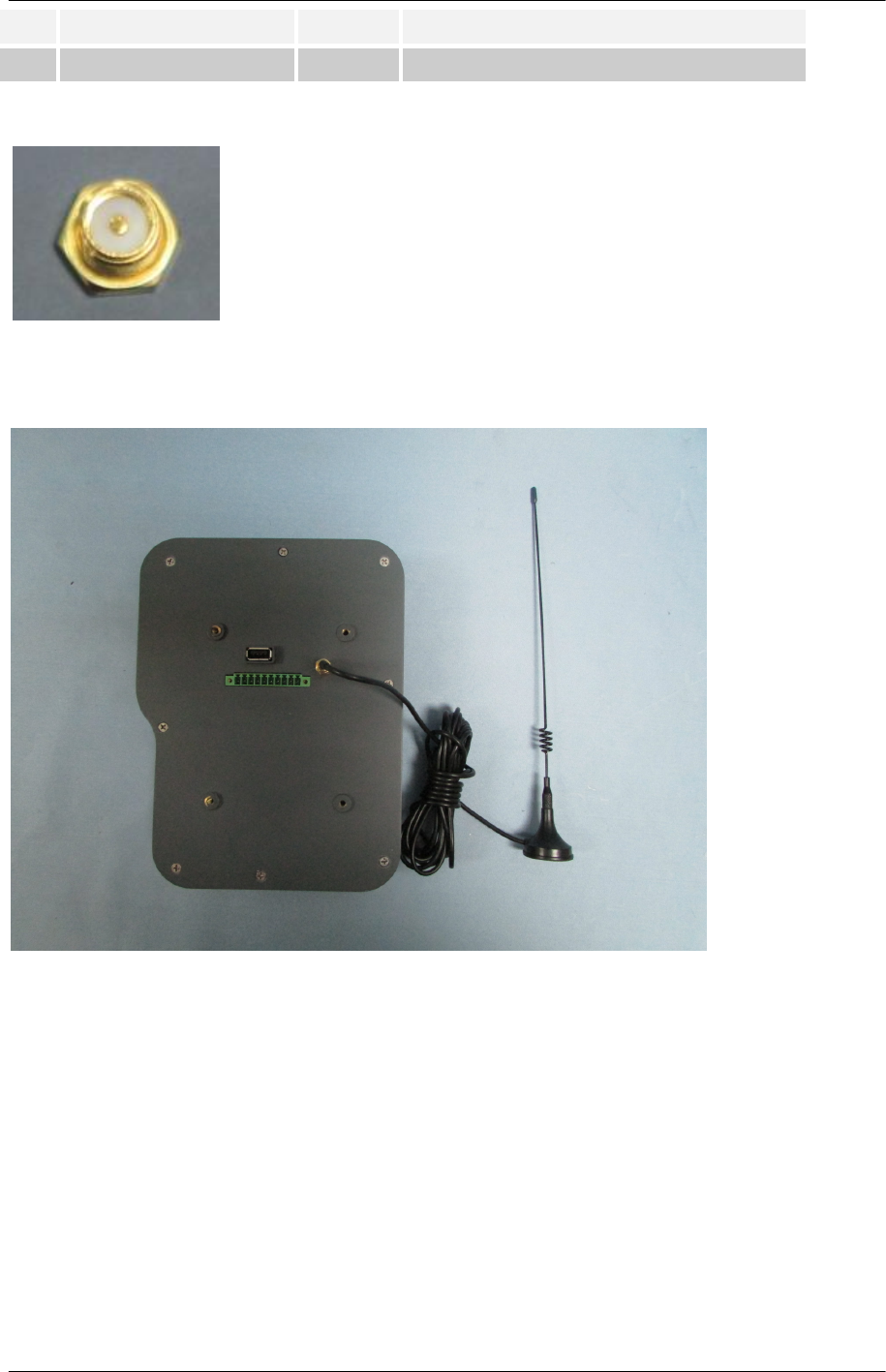
4.2.3 3G Antenna port
It is a RP SMA connector, the whorl is non-standard.
4.2.4 3G Antenna
The antenna is only being used to the EUT.The antenna gain is 5.12 dBi for Cellular & 6.12 dBi for PCS

All rights reserved Page 12, Total 13
5 Tips
WasteDisposal
Itisrecommendedtodisassemblethedevicebeforeabandoningitinconformitywithlocalregulations.
Pleaseensurethattheabandonedbatteriesaredisposedaccordingtolocalregulationsonwastedisposal.Do
notthrowbatteriesintofire(explosive)orputincommonwastecanister.Productsorproductpackageswith
thesignof“explosive”shouldnotbedisposedlikehouseholdwastebutdeliveredtospecializedelectrical&
electronicwasterecycling/disposalcenter.Properdisposalofthissortofwastehelpsavoidingharmand
adverseeffectuponsurroundingsandpeople’shealth.Pleasecontactlocalorganizationsor
recycling/disposalcenterformorerecycling/disposalmethodsofrelatedproducts.
Complywiththefollowingsafetytips:
Donotuseincombustibleandexplosiveenvironment
Keepawayfromcombustibleandexplosiveenvironmentforfearofdanger.
Keepawayfromallenergizedcircuits.
Operatorsshouldnotremoveenclosurefromthedevice.Onlythegrouporpersonwithfactorycertification
ispermittedtoopentheenclosuretoadjustandreplacethestructureandcomponentsofthedevice.Donot
changecomponentsunlessthepowercordisremoved.Insomecases,thedevicemaystillhaveresidual
voltageevenifthepowercordisremoved.Therefore,itisamusttoremoveandfullydischargethedevice
beforecontactsoastoavoidinjury.
Unauthorizedchangestothisproductoritscomponentsareprohibited.
Intheaimofavoidingaccidentsasfaraspossible,itisnotallowedtoreplacethesystemorchange
componentsunlesswithpermissionandcertification.PleasecontactthetechnicaldepartmentofVantronor
localbranchesforhelp.
Payattentiontocautionsigns.
Cautionsignsinthismanualremindofpossibledanger.Pleasecomplywithrelevantsafetytipsbeloweach
sign.Meanwhile,youshouldstrictlyconformtoallsafetytipsforoperationenvironment.
Notice
Consideringthatreasonableeffortshavebeenmadetoassureaccuracyofthismanual,Vantronassumes
noresponsibilityofpossiblemissingcontentsandinformation,errorsincontents,citations,examples,and
sourceprograms.
Vantronreservestherighttomakenecessarychangestothismanualwithoutpriornotice.Nopartofthis
manualmaybereprintedorpubliclyreleasedinformsofphotocopy,tape,broadcast,e‐document,etc.
AV 7 User’s Manual (HW)

All rights reserved Page 13, Total 13
US Office: Vantron Technology, Inc.
Address: 1292 Kifer Road #807
Sunnyvale, CA 94086
Tel: 510-304-7666
Email: sales@vantrontech.com
China Office: Chengdu Vantron Technology, Ltd
Address: 3rd floor, 3rd building, No.9, 3rd WuKe East
Street, WuHou District,
Chengdu, P.R. China 610045
Tel: 86-28-8512-3930/3931, 8515-7572/6320
Email: sales@vantrontech.com.cn
AV 7 User’s Manual (HW)
FCC NOTE:
This device complies with Part 15 of the FCC Rules.
Operation is subject to the following two conditions: (1) this device may not cause harmful
interference, and (2) this device must accept any interference received, including interference that
may cause undesired operation.
THE MANUFACTURER IS NOT RESPONSIBLE FOR ANY RADIO OR TV INTERFERENCE
CAUSED BY UNAUTHORIZED MODIFICATIONS OR CHANGE TO THIS EQUIPMENT. SUCH
MODIFICATIONS OR CHANGE COULD VOID THE USER’S AUTHORITY TO OPERATE THE
EQUIPMENT.
This equipment has been tested and found to comply with the limits for a Class B digital device,
pursuant to part 15 of the FCC Rules. These limits are designed to provide reasonable protection
against harmful interference in a residential installation. This equipment generates, uses and can
radiate radio frequency energy and, if not installed and used in accordance with the instructions,
may cause harmful interference to radio communications. However, there is no guarantee that
interference will not occur in a particular installation. If this equipment does cause harmful
interference to radio or television reception, which can be determined by turning the equipment
off and on, the user is encouraged to try to correct the interference by one or more of the
following measures:
-- Reorient or relocate the receiving antenna.
-- Increase the separation between the equipment and receiver.
-- Connect the equipment into an outlet on a circuit different from that to which the receiver is
connected.
-- Consult the dealer or an experienced radio/TV technician for help.
To maintain compliance with FCC’s RF exposure guidelines, this equipment should be installed
and operated with a minimum distance of 20cm between the radiator and your body.