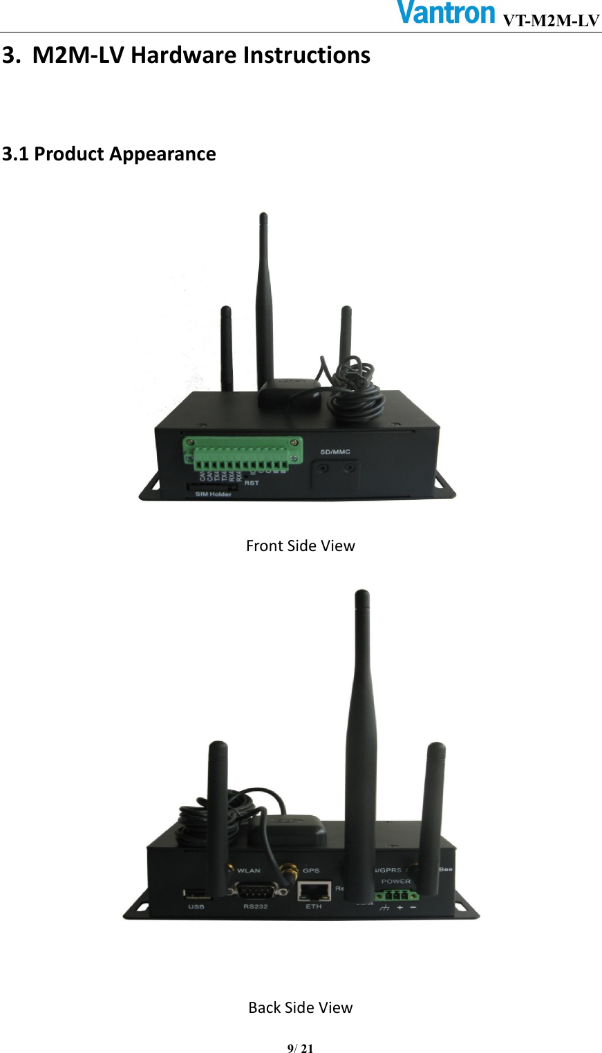
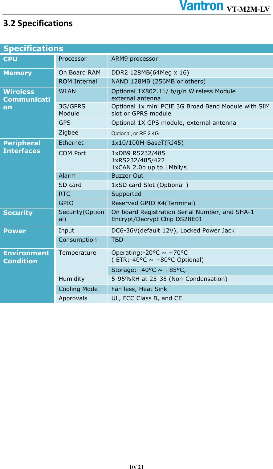
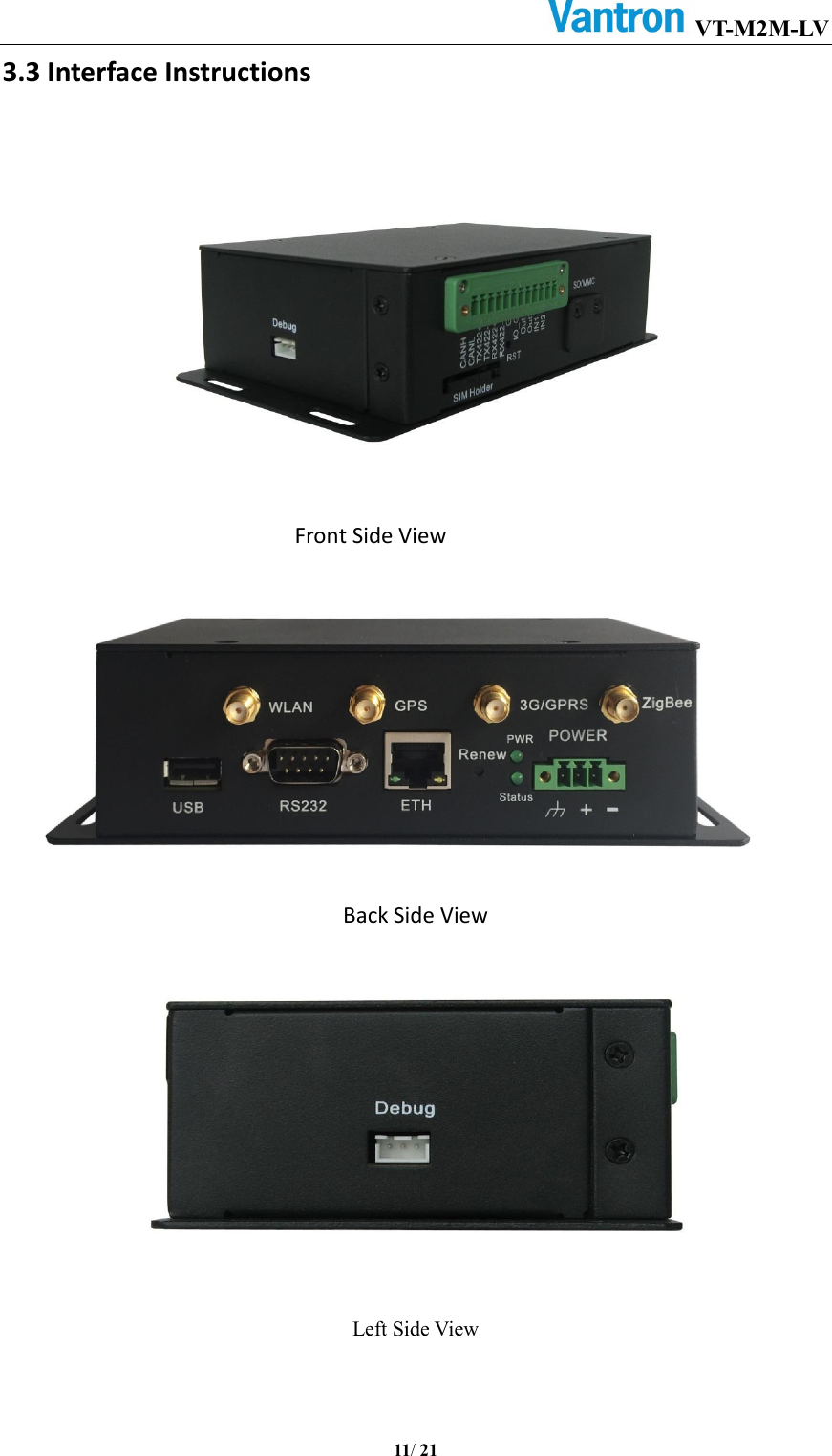
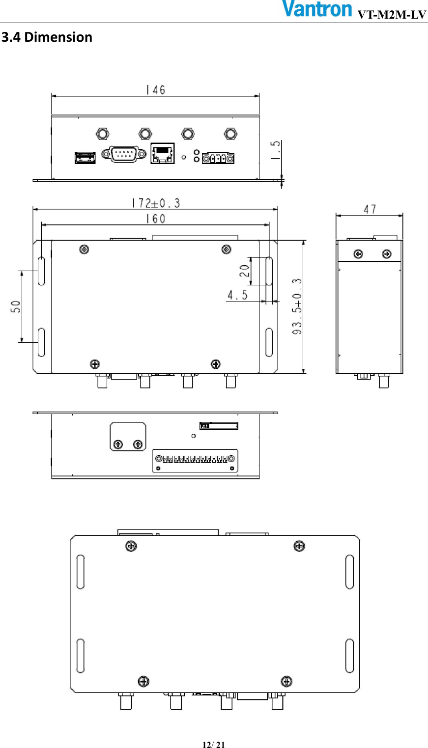
Chengdu Vantron Technology VTM2M-LV M2M Gateway User Manual

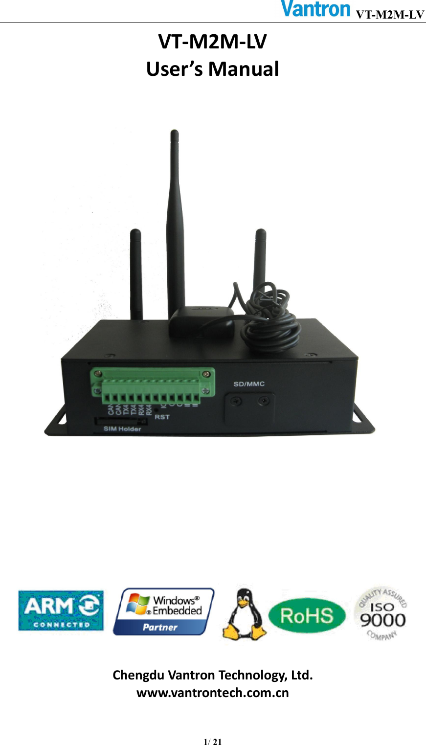
Chengdu Vantron Technology, Ltd. M2M Gateway

User Manual

VT-M2M-LV       1/ 21  VT-M2M-LV User’s Manual                   Chengdu Vantron Technology, Ltd. www.vantrontech.com.cn
VT-M2M-LV       2/ 21  Revision History:  No.  Version  Description  Date 1  V1.0  First release  Nov.8, 2012 2  V2.0  Upgrade PCB to Revision 2  Oct.18, 2013 3  V3.0  Upgrade PCB to Revision 3, move GPS to on board, change WiFi to on board module.  Sept.28, 2014 4  V3.1  Add FCC and IC warning statement  March.16,2015
VT-M2M-LV       3/ 21  Table of Contents 1. Foreword ...................................................................................................................................4 1.1 Copyright Notice ........................................................................................................................4 1.2 Notes ..........................................................................................................................................4 1.3 Statement ...................................................................................................................................4 1.4 Disclaimer ...................................................................................................................................4 1.5 Limitation of Liability/Non-warranty ..........................................................................................5 1.6 Safety Instructions ......................................................................................................................5 1.7 Precautions .................................................................................................................................5 1.8 Safety Instructions for Power Cables and Accessories ...............................................................5 2. Overview ...................................................................................................................................7 2.1 Introduction ...............................................................................................................................7 2.2 Product Series ............................................................................................................................8 3. M2M-LV    Hardware Instructions ..............................................................................................9 3.1 Product Appearance ...................................................................................................................9 3.2 Specifications ...........................................................................................................................10 3.3 Interface Instructions ...............................................................................................................11 3.4 Dimension ................................................................................................................................12 3.5 Interface Description ................................................................................................................13 3.5.1 Power Interface ........................................................................................................13 3.5.2 Ethernet Interface .....................................................................................................14 3.5.3 D Sub-9 RS232 or RS485 Connector ..........................................................................15 3.5.4 RS232/422/485,CAN,External IO Connector .............................................................16 3.5.5 LED ............................................................................................................................17 3.5.6 SIM Card ....................................................................................................................17 3.5.7 DEBUG .......................................................................................................................17 3.5.8 Renew button............................................................................................................18 3.5.9 Reset button ..............................................................................................................18 3.5.10 SD/MMC socket ......................................................................................................18 4. Tips .......................................................................................................................................... 19
VT-M2M-LV       4/ 21  1. Foreword 1.1 Copyright Notice While all information contained herein have been carefully checked to assure its accuracy  in  technical  details  and  printing,  Vantron  assumes  no  responsibility resulting from any error or features of this manual, or from improper uses of this manual  or  the  software.  Please  contact  our  technical  department  for  relevant operation solutions if there is any problem that cannot be solved according to this manual.   Vantron  reserves  all  rights  of  this  manual,  including  the  right  to  change  the content,  form,  product  features,  and  specifications  contained  herein  at  any  time without  prior  notice.  The  latest  version  of  this  manual  is  at www.vantrontech.com.cn. Please contact Vantron for further information:   Vantron Technology(Vantron) E-mail: sales@vantrontech.com The trademarks and registered trademarks in this manual are properties of their respective owners. No part of this manual may be copied, reproduced, translated or sold. No changes or other purposes are permitted without the prior written consent of Vantron.     Vantron reserves the right of all publicly-released copies of this manual. 1.2 Notes Applicable notes are listed in the following table:  Sign  Notice Type  Description  Notice  Important information and regulations  Caution  Caution for latent damage to system or harm to personnel 1.3 Statement It  is  recommended  to  read  and  comply  with  this  manual  before  operating VT-M2M LV which provides important guidance and helps decreasing the danger of injury, electric shock, fire, or any damage to the device.     1.4 Disclaimer Vantron  assumes  no  legal  liability  of  accidents  resulting  from  failure  of conforming to the safety instructions.
VT-M2M-LV       5/ 21  1.5 Limitation of Liability/Non-warranty For direct or indirect damage to this device or other devices of Vantron caused by failure  of  conforming  to  this  manual  or  the  safety  instructions  on  device  label, Vantron assumes neither warranty nor legal liability even if the device is still under warranty. The  VT-M2M-LVshould  be  installed,  debugged  and  maintained  by  professional people.   The  outside  antennas  are  not  permitted  to  be  installed  or  to  be  changed  by non-professional  people.  To  run  the  device  normally,  only  specify  antennas  are approved to be assembled together by professional people. Unit shall be used with indoor-use antenna only. No antenna for this unit can be installed outdoor. 1.6 Safety Instructions  Keep and comply with all operation instructions, warnings, and information.    Pay attention to warnings on this device.  Read the  following  precautions so  as to decrease  the  danger  of injury,  electric shock, fire, or any damage to the device.      1.7 Precautions  Pay attention to the product labels/safety instructions printed on silk screens.  Do not try repairing this product unless declared in this manual.  Keep away from heat source, such as heater, heat dissipater, or engine casing.    Do not insert other items into the slot (if any) of this device.   • Keep the ventilation slot ventilated for cooling. •System fault may arise if other items are inserted into this device.  Installation:  ensure  correct  installation  according  to  instructions  from  the manufacturer with recommended installation tools.    Ensure ventilation and smoothness according to relevant ventilation standard.    1.8 Safety Instructions for Power Cables and Accessories Proper power source only Start only with power source that satisfies voltage label and the voltage necessary according to this manual. Please contact technical support personnel of Vantron for any uncertainty about the requirements of necessary power source.   Use tested power source   This  product  still  contains  a  button  lithium  battery  as  a  real-time  clock  after  its external  power  source  is  removed  and  therefore  should  not  be  short-circuited
VT-M2M-LV       6/ 21  during transportation or placed under high temperature.     Place cables properly: Do not place cables at any place with extrusion danger.    Cleaning Instructions  Please power off before cleaning the device.  Do not use spray detergent.    Clean with a damp cloth.  Do not try cleaning exposed electronic components unless with a dust collector.    Support for special fault: Power off and contact technical support personnel of Vantron in case of the following faults:  The device is damaged.  The temperature is excessively high.    Fault is still not solved after the operation according to the manual.
VT-M2M-LV       7/ 21   2. Overview 2.1 Introduction Thank  you  for  choosing  Vantron.  It  is  our  commitment  to  provide  our  valued customers  with  the  embedded  devices  equipped  with  the  state-of-the-art technology and the best product services.   Vantron’s M2M products  are  based on the  most  advanced ARM and  Intel Atom processors  and  have  low-power  consumption  and  high  integration.  The  products are  designed  for  applications  of  M2M  in  industrials,  medicals,  financial,  retail, vehicle, and transportations etc.
VT-M2M-LV       8/ 21  2.2 Product Series  Order Code VT-M2M-LV-4-1M-1F-3GWZP-I                                                 Order Examples: VT-M2M-LV-4-1M-1F  456Mhz ARM9 Processor, 128MB DDR2, 128MB NAND VT-M2M-LV-3-1M-1F-W  375Mhz ARM9 Processor, 128MB DDR2, 128MB NAND, WLAN VT-M2M-LV-3-1M-2F-3GW  375Mhz ARM9 Processor, 128MB DDR2, 256MB NAND 3G module, WLAN  Accessories: Install Mechanical tools,1pc Power Adapter (Optional),1pc IO Terminal (12x3.81mm) (Optional),1pc Power Terminal (3x3.81mm) (Optional),1pc 3G Antenna(Optional),1pc WiFi Antenna(Optional),1pc GPS Antenna(Optional),1pc   Version: I: Extended Temperature Blank:Commercial temperature Wireless  Module  Option:  2G:  2G,  3G:  3G W:WLAN,Z:Zigbee,P:GPS  NAND Memory Size:1:128MB; 2:256MB   DDR Memory Size:    1:128MB; 2:256MB CPU Speed:        3: 375MHZ;      4: 456GHZ
VT-M2M-LV       9/ 21  3. M2M-LV Hardware Instructions 3.1 Product Appearance    Front Side View      Back Side View
VT-M2M-LV       10/ 21  3.2 Specifications          Specifications CPU  Processor ARM9 processor  Memory  On Board RAM DDR2 128MB(64Meg x 16) ROM Internal  NAND 128MB (256MB or others) Wireless   Communication WLAN  Optional 1X802.11/ b/g/n Wireless Module external antenna 3G/GPRS Module Optional 1x mini PCIE 3G Broad Band Module with SIM slot or GPRS module GPS  Optional 1X GPS module, external antenna Zigbee  Optional, or RF 2.4G Peripheral Interfaces Ethernet  1x10/100M-BaseT(RJ45) COM Port  1xDB9 RS232/485 1xRS232/485/422 1xCAN 2.0b up to 1Mbit/s Alarm  Buzzer Out SD card  1xSD card Slot (Optional ) RTC  Supported GPIO  Reserved GPIO X4(Terminal) Security  Security(Optional) On board Registration Serial Number, and SHA-1 Encrypt/Decrypt Chip DS28E01 Power  Input  DC6-36V(default 12V), Locked Power Jack Consumption  TBD Environment Condition Temperature  Operating:-20°C ~ +70°C ( ETR:-40°C ~ +80°C Optional) Storage: -40°C ~ +85°C,   Humidity  5-95%RH at 25-35 (Non-Condensation) Cooling Mode  Fan less, Heat Sink Approvals  UL, FCC Class B, and CE
VT-M2M-LV       11/ 21  3.3 Interface Instructions           Front Side View  Back Side View  Left Side View
VT-M2M-LV       12/ 21  3.4 Dimension
VT-M2M-LV       13/ 21  3.5 Interface Description   3.5.1 Power Interface       Power connector outlook   Pin Description 1  Shell ground 2  Power input range 6-36V 3  Ground      PIN1
VT-M2M-LV       14/ 21    3.5.2 Ethernet Interface Standard RJ45 interface, supporting 10M/100M self-adaptation, this is a standard RJ45 Ethernet port  Pin  Description  Remarks 1  TXP  IO 2  TXN  IO 3  RXP  IO 4  CT  P 5  CT   6  RXN  IO 7  NC   8  MH_GND  P 9  LEDG+  P 10  LINKLED   11  LEDY-  P 12  ACTIVITYLED
VT-M2M-LV       15/ 21    3.5.3 D Sub-9 RS232 or RS485 Connector Standard vertical DB-9 male connector.   Pin  Description  Remarks 1  NC or RS485_A   2  RXD2 or RS485_B  I 3  TXD2  O 4  NC   5  DGND  P 6  NC   7  NC   8  NC   9  NC
VT-M2M-LV       16/ 21    3.5.4 RS232/422/485,CAN,ExternalIO Connector 12pins 3.81 pitch terminal with screw lock   Load capacity: more than 128 nodes/RS485 channel-- bit rate:115200 CAN: The bit rate can be programmed to a maximum of 1Mbit/s     Pin  Description  Remarks 1  CANH   2  CANL   3  TX422+   4  TX422-   5  RX422+/RS485_2_A/STXD3  Jumper Set 6  RX422-/ RS485_2_B/SRXD3  Jumper Set 7  DGND  P 8  IO_GND  P 9  GPIO_OUT1  IO 10  GPIO_OUT2  IO 11  GPIO_IN1  IO 12  GPIO_IN2  IO                    PIN1
VT-M2M-LV       17/ 21        3.5.5 LED    PWR LED: lightindicatesystem power OK(main power up);offindicate system power turn off Status LED: User can define by themself.          3.5.6SIM Card Push the small button on the left of SIM Card Holder, and install the SIM card to the holder. Then push the holder into the Slot.        3.5.7DEBUG CONN,BOX,1x3x2.0,TH,JST,VERT(JST: B3B-PH-K-S(LF)(SN)), User  can show the  debug message and use keyboardinput debug command.      Pin Description 1 DGND 2 SUART2_RXD 3 SUART2_TXD PIN1
VT-M2M-LV       18/ 21     3.5.8Renew button    Renew  button:long  press  this  button  will  restore  the  factory setting,  the  long  press  time can  be setting by user    3.5.9 Reset button    Reset button:short press this button will resetthis M2M device.     3.5.10 SD/MMC socket    This is standard SD card socket , user can save data on this storage. You can remove this metal cover by use screw-driver tool.
VT-M2M-LV       19/ 21  4. Tips Waste Disposal It is recommended to disassemble the device before abandoning it in conformity with  local  regulations.  Please  ensure  that  the  abandoned  batteries  are  disposed according  to  local  regulations  on  waste  disposal.  Do  not  throw  batteries  into  fire (explosive)  or  put  in  common  waste  canister.  Products  or  product  packages  with the sign of “explosive” should not be disposed like household waste but delivered to  specialized  electrical &electronic  waste  recycling/disposal  center.  Proper disposal  of  this  sort  of  waste  helps  avoiding  harm  and  adverse  effect  upon surroundings  and  people’s  health.  Please  contact  local  organizations  or recycling/disposal center for more recycling/disposal methods of related products.   Comply with the following safety tips:   Do not use in combustible and explosive environment  Keep away from combustible and explosive environment for fear of danger.   Keep away from all energized circuits.   Operators  should  not  remove  enclosure  from  the  device.  Only  the  group  or person with  factory  certification is permitted to open the  enclosure to adjust and replace  the  structure  and  components  of  the  device.  Do  not  change  components unless the power cord is removed. In some cases, the device may still have residual voltage even if the power  cord is removed. Therefore, it is a must to remove and fully discharge the device before contact so as to avoid injury.     Unauthorized changes to this product or its components are prohibited.     In the aim of avoiding accidents as far as possible, it is not allowed to replace the system  or  change  components  unless  with  permission  and  certification.  Please contact the technical department of Vantron or local branches for help.      Pay attention to caution signs.   Caution  signs  in  this  manual  remind  of  possible  danger.  Please  comply  with relevant safety tips below each sign. Meanwhile, you should strictly conform to all safety tips for operation environment.   Notice Considering  that  reasonable  efforts  have  been  made  to  assure  accuracy  of  this manual,  Vantron  assumes  no  responsibility  of  possible  missing  contents  and information, errors in contents, citations, examples, and source programs.   Vantron reserves the right to make necessary changes to this manual without prior notice. No part of this manual may be reprinted or publicly released in for
                                                    VT-M2M-LV               20/21  FCC Warning This device complies with FCC class B Rules. Operation is subject to the Following conditions. This device may not cause harmful interference. This device must accept any interference received, including interference that may cause undesired operation.  Note: This equipment has been tested and found to comply with the limits for a Class B digital device, pursuant to part 15 of the FCC Rules. These limits are designed to provide reasonable protection against harmful interference in a residential installation. This equipment generates, uses and can radiate radio frequency energy and, if not installed and used in accordance with the instructions, may cause harmful interference to radio communications. However, there is no guarantee that interference will not occur in a particular installation. If this equipment does cause harmful interference to radio or television reception, which can be determined by turning the equipment off and on, the user is encouraged to try to correct the interference by one or more of the following measures:  —Reorient or relocate the receiving antenna. —Consult the dealer or an experienced radio/TV technician for help. -- Connect the equipment into an outlet on a circuit different from that to which the receiver is connected.   -- Consult the dealer or an experienced radio/TV technician for help.    Any modification to the product is not permitted unlessauthorized by Vantron.It’s not allowed to disassemble theproduct, it is not allowed to replace the system or change components unless with permission and certification. Please contact the technical support department of Vantron or local branches for help.   IC statement This device complies with Industry Canada licence-exempt RSS standard(s). Operation is subject to the following two conditions: (1) this device may not cause interference, and (2) this device must accept any interference, including interference that may cause undesired operation of the device.  Le présent appareil est conforme aux CNR d'Industrie Canada applicables aux appareils radio exempts. L'exploitation est autorisée aux deux conditions suivantes : (1) l'appareil ne doit pas produire de brouillage, et (2) l'utilisateur de l'appareil doit accepter tout brouillage radioélectrique subi, même si le brouillage est susceptible d'en compromettre le fonctionnement.   RF exposure warning This equipment must be installed and operated in accordance with provide instructions and the antenna used for this transmitter must be installed to provide a separation distance of at least 20 cm from all persons and must not be co-located or operation in conjunction with any other antenna or transmitter. End-users and installers must be provide with antenna installation instructions and transmitter operating conditions for satisfying RF exposure compliance.  Product Name: M2M Gateway, Model: VT-M2M-LV FCC ID: 2AAGEVTM2M-LV, IC:1152A-VTM2MLV, contains FCC ID:RI7HE910, IC:5131A-HE910 FCC ID: 2AAGEVTM2M-LV, IC:1152A-VTM2MLV, contains FCC ID:RI7DE910-DUAL, IC:5131A-DE910DUAL FCC ID: 2AAGEVTM2M-LV, IC:1152A-VTM2MLV, contains FCC ID: RI7GE910Q3, IC: 5131A‐GE910Q3
VT-M2M-LV       21/ 21             US Office: Vantron Technology, Inc.     Address: 1292 Kifer Road #807,   Sunnyvale, CA 94086 Tel: 510-304-7666     Email:   sales@vantrontech.com  China Office: Chengdu Vantron Technology, Ltd. Address: No.5 GaoPeng Road, Hi-Tech Zone,Chengdu, P.R. China 610045 Tel: 86-28-8512-3930/3931Email: sales@vantrontech.com.cn

Navigation menu