Chenghai Udirc Toys UA221803001 U47 (Transmitter) User Manual 15 UA22 UserMan r1
Chenghai Udirc Toys Co.,Ltd U47 (Transmitter) 15 UA22 UserMan r1
15_UA22 UserMan r1
Operations Guide
U47
NOVA
Equipped with WIFI Camera
2
Catalog
Instruction for Drone and Controller 3
Installing & Removing Spare Parts 7
Pre-Flight Checklist 10
Pre-Flight Operation Instructions 11
Functions 14
Using App 16
Spare Parts 17
Troubleshooting 25
www.udirc.com
3
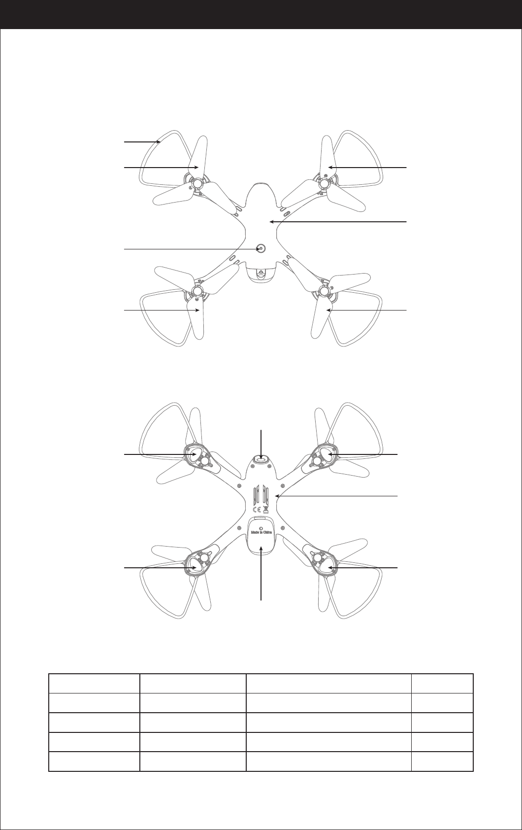
Instruction For Drone And Controller
Drone
A Propeller
Left Right
Front
Rear
Power Switch
B Propeller
Propeller Guard
B Propeller
A Propeller
Camera
Drone Battery
Front LED
(Green)
Front LED
(Green)
Drone Bottom
Housing
Rear LED
(Red)
Rear LED
(Red)
Drone
Cover Housing
Specifications
Drone Size
Drone Weight
Propeller Diameter
248x280x59.0mm
138g
110mm
Max Streaming Video Range/Radius
40m
50m
120 mins
Flying Time 10 mins
Drone Battery 3.7V 1000mAh
Main Motor 8520x4
Max Flying Height 15m
Charging Time for Drone Battery
Max Flying Distance/Radius
www.udirc.com
4
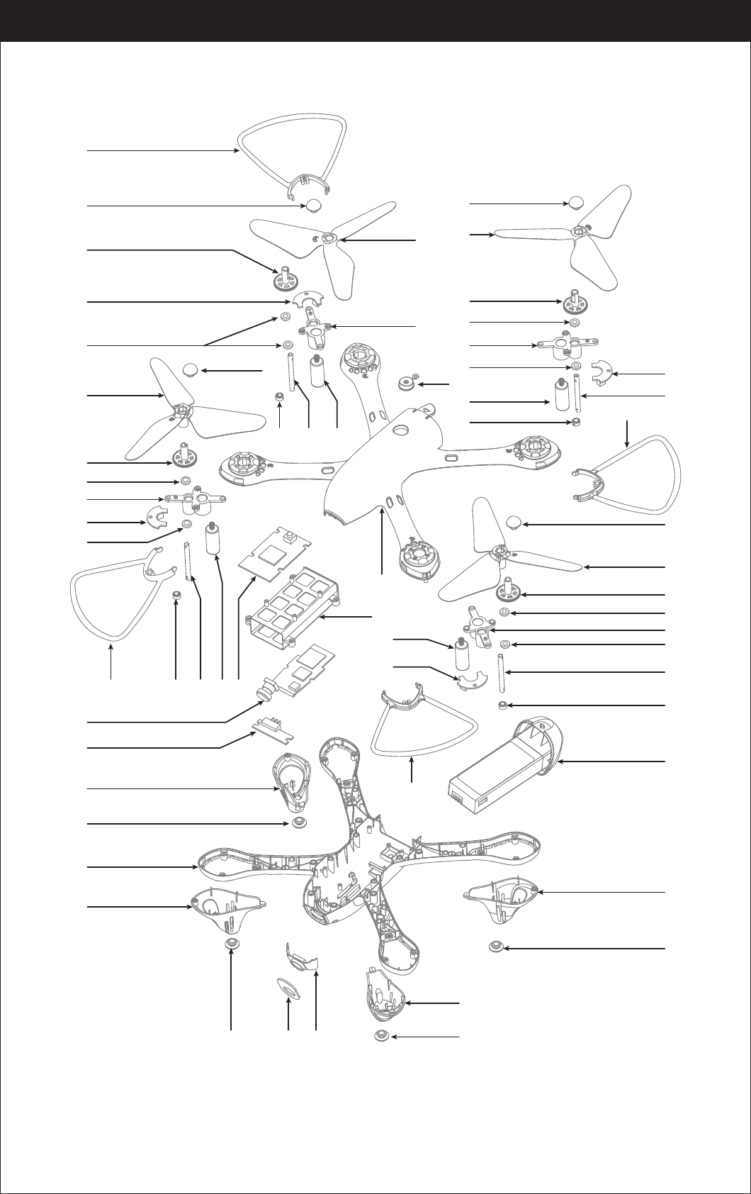
Exploded View
www.udirc.com
01
02
03
07
04
05
06
11
04
06
07
12
06
01 08 13 1409
15
16
17
18
19
20
18
22
19 21
02
11
04
06
07
06
23
13
09
24
25
08
01
02
09 1008
02
03
04
06
07
06
08
09
27
10
26
01
18
19
18
19
5
16 Camera Board
15
No. Name NameNo.
1 Propeller Guards
17 Battery Switchboard
2 Propeller Piston
18 LED Cover
3 A Propeller
19 Cushion
4 Transmission Gear
20 Drone Bottom Housing
5Rear A LED Board
(Red LED/White Plug)
21 Camera Component
6 Copper ring
22 Camera Organic Board
7 Motor holder
23 Switch Button
8 Spindle steel pipe
24 Drone Housing Cover
9 Steel pipe fixings
25 Rear B LED Board (Red LED/Red Plug)
10 Propeller A Motor
B Propeller
26 Front A LED Board (Green LED/White Plug)
11
Front B LED Board
(Green LED/Red Plug) 27 Battery Compartment
12
Propeller B Motor13
Receiving Board14
Receiving Board holder
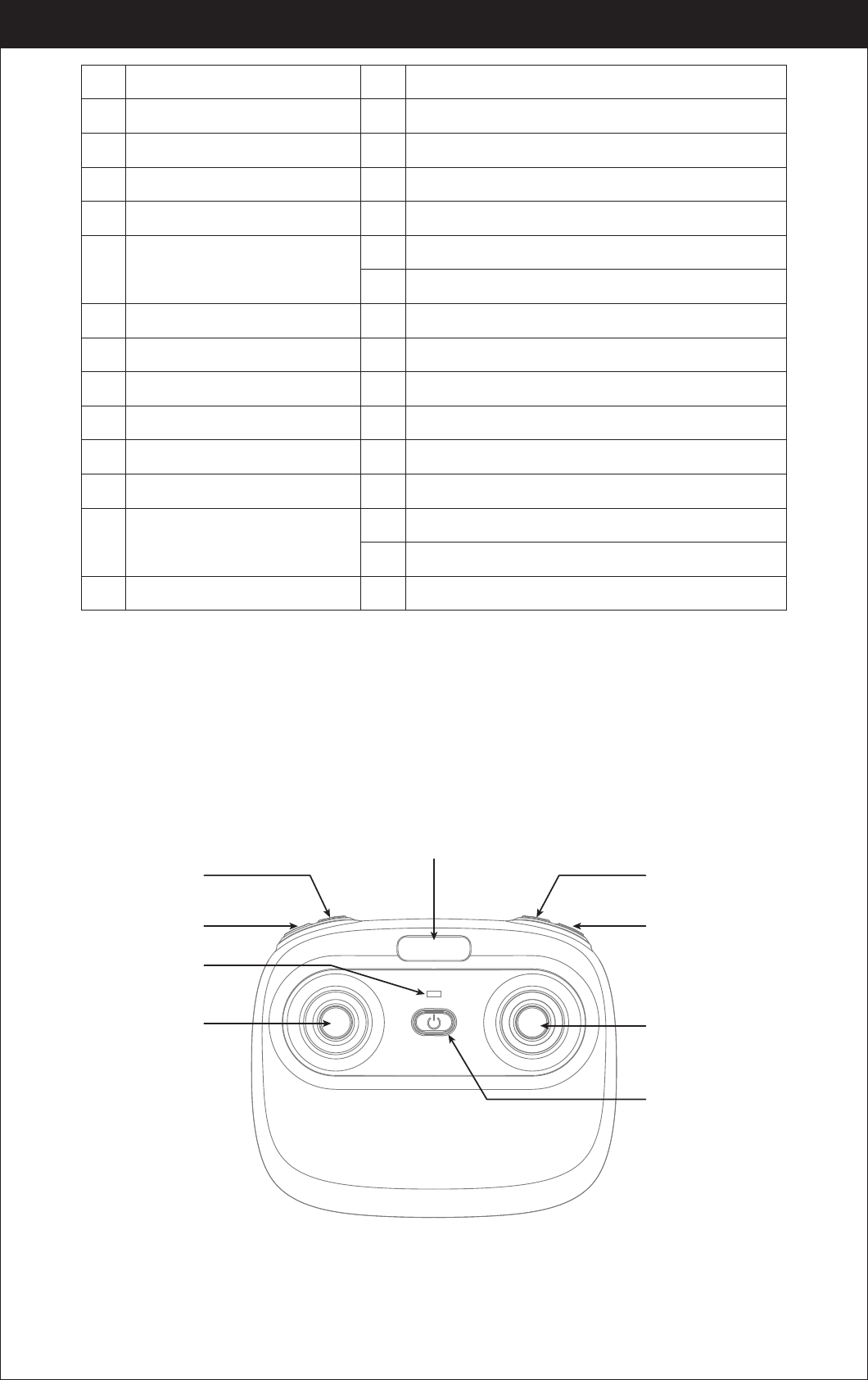
Controller
www.udirc.com
Power Indicator
Phone Holder Slot
Left Stick Right Stick
Heading Hold
Mode
One Button Take
Off / Landing/
Emergency Stop
Button
Power Switch
Photo
Video
Notice: Taking photo and recording video are available after connecting with
smart phone.
6
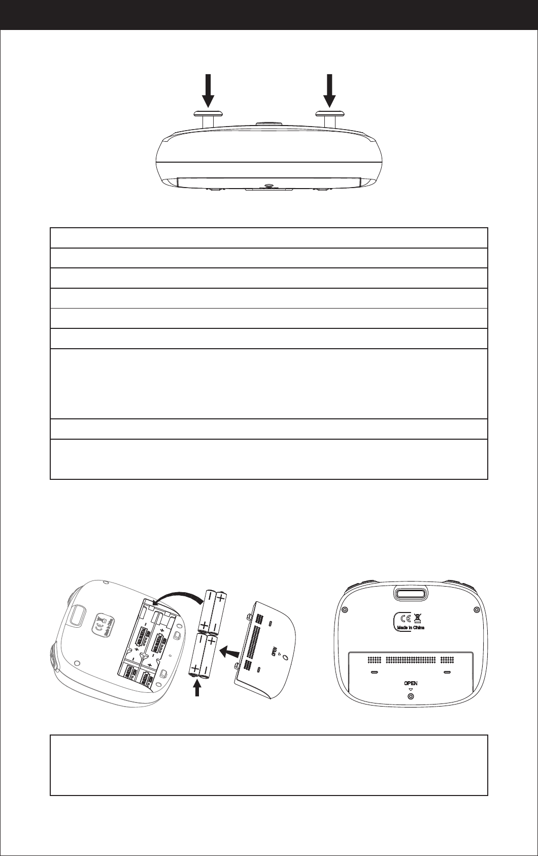
Controller Button Functions
Battery Installation
Open the battery cover on the back side of the controller, insert 4 AA batteries
following the polarity indicators. ( Picture 1/2, battery is not included)
1.Make sure the electrodes are correct. 3.Do not mix different kinds of batteries.
2.Do not mix new with old batteries. 4.Do not charge the non rechargeable battery.
Notice:
www.udirc.com
High/Medium/Low Speed
Mode (Press Down)
Trimmer Mode Button
(Press Down)
Alkaline Battery
Picture 1 Picture 2
Battery Cover
High / Medium / Low Speed button:
Left Stick:
Right Stick:
Power Switch:
Press to right switch to High /Medium/ Low Speed.
Move the Stick to forward / backward / left / right to fly the drone up / down / turn left / turn right.
Move the Stick to forward / backward / left / right to fly the drone forward / backward / left / right.
Trimmer Mode Button:
Press down the left stick and turn to the required trimmer direction,
then it will adjust the direction accordingly. Release the stick to exit trimmer mode.
Push up the power switch to turn on the controller, and pull down to turn off.
Heading Hold Mode:
Press to enter Heading Hold Mode. Press again to exit Heading Hold Mode.
Take Off / Landing / Emergency Stop Button:
automatically. Press again and the drone will land automatically. Press and hold the button for
more than 1 second for an emergency landing, the drone propellers will stop and it will land
immediately.
Press once and the drone will take off
Video:
Press down the button, start to record video.
Photo:
Press down the button, start to photograph.
7
Drone Battery
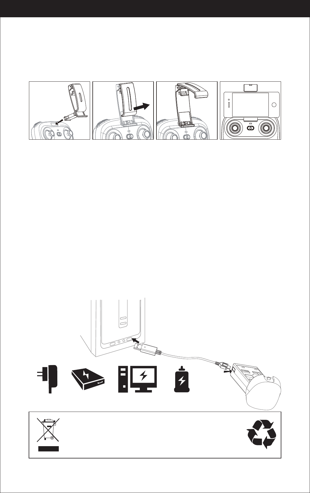
Phone Installation Instruction
Li-Po Battery Disposal & Recycling
Wasted Lithium-Polymer batteries must not be placed with household
trash. Please contact local environmental or waste agency or the
supplier of your model or your nearest Li-Po battery recycling center.
Charging Instruction for Drone Battery
Parts installation
* For faster charging, it is recommended to use an adapter with 5V 2A output current
(not included) to charge the battery
Notice:Make sure that the button on phone is not clamped.
Power BankPhone Charger Computer Charging Car Charger
1. Connect the drone battery with USB cable first and then choose one of the
method as below picture shown to connect with USB plug.
2. The red USB indicator light keeps bright when charging and the light turns
green when fully charged.
www.udirc.com
Picture 3 Picture 4 Picture 5 Picture 6
1. Take out the phone holder and insert into the controller(Picture 3).
2. Pull out upper lamp of the holder ( Picture 4/5), put the phone into the holder,
then release the clamp, and the phone will be fixed on the holder( Picture 6).
8
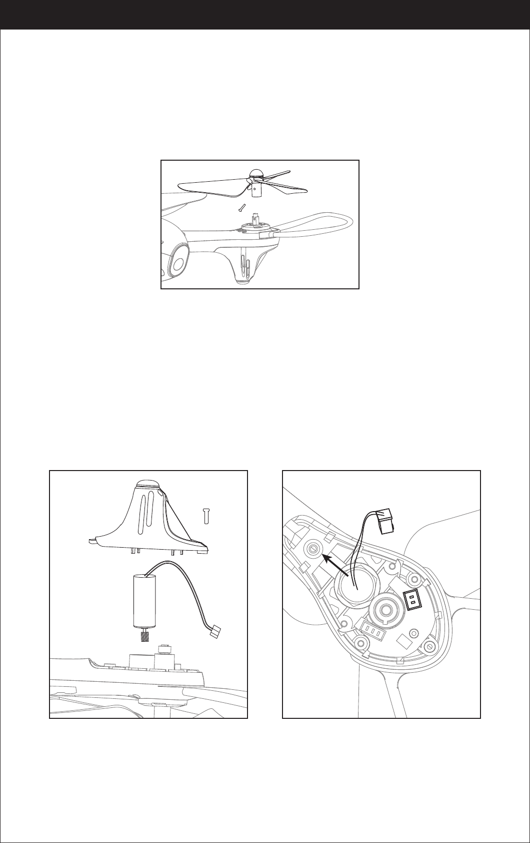
Propeller installation diagram
When install, put the propeller hole aims to the drone shaft hole, and then press
down until bottom, tighten it with screw, and then put on propeller cover( Pic 8);
when disassemble, loose the screw and then pull out the propeller.
Notice: When install, please make sure correct propeller in place, otherwise
the drone can not work well.
Picture 9
Picture 10
Picture 8
Warning: When pick up the motor, please don’t damage the LED board.
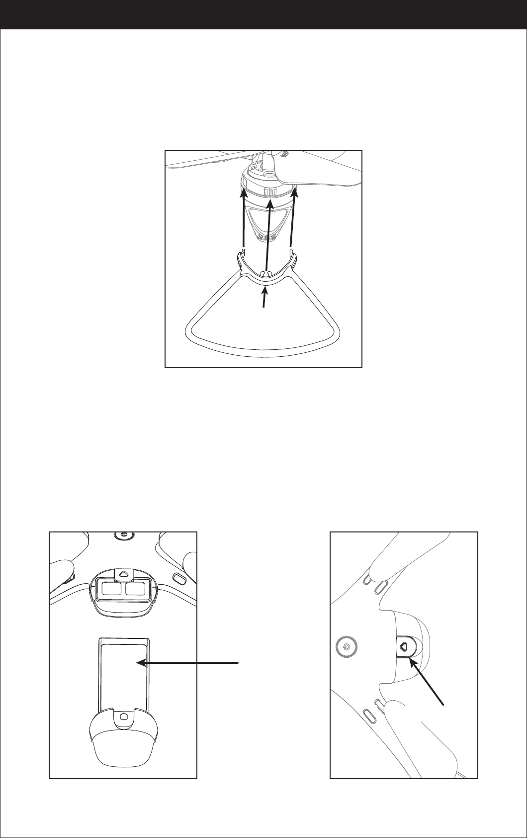
Motors Replacement Diagram
1. To remove the motor, remove the screw from the lampshade first,then take
the lampshade out, unplug the motor connector from LED board and then take
the defective motor out ( Picture 9) .
2. To install the motor, put the motor into motor holder( make sure the motor
press down and also the gears are pairing) and plug the required motor
connector into the LED board socket. Put on the motor cover and fix it with screw.
Notice: The motor’s rotating direction should be the same, or it will not work.
Tips: The motor is consumable. If it is damaged, please buy new motor for
replacement.
www.udirc.com
䳃㥩䳃䏠た㼜絁椚곡
䭽盪㣢倰ぢ䶓佞կ
9
When install the propeller guard, attach one buckle to the arm and then push
another buckle in until they locks (Picture 11).
When remove the propeller guard, take it out from buckles on both sides and pull
out the propeller guards.
Propeller guards assembly instruction
When install, push the battery to the end(Picture 12);
When disassemble,you need to squeeze up and down of the battery buckle and
then put out the lipo battery box is fine.
Battery installation diagram
www.udirc.com
Picture 12 Picture 13
Sticker face up
Picture 11
Push here
Battery buckle
10
Pre-Flight Checklist
1. Ensure that the drone battery and controller batteries are fully charged.
2. Ensure that the left stick of the controller is in the middle position.
3. Strictly follow the instructions for the order for turning on and turning off the
controller and drone. Turn on the controller power first and then turn on the
drone power before flying; Turn off the drone power first and then turn off the
controller power when fishing flying. Improper on/off sequence may cause the
drone to fly out of control and could threaten your safety or the safety of others.
Please cultivate a correct habit of turn on and turn off.
4. Ensure the connection between the battery and motor is solid. Vibration during
use may cause a bad connection and the drone could become difficult to control.
5. Improper operation may cause the drone to crash, which may cause motor
defects that could affect flying ability. If this occurs, visit the local distributor to
buy new replacement parts,so that the drone will return to its best status.
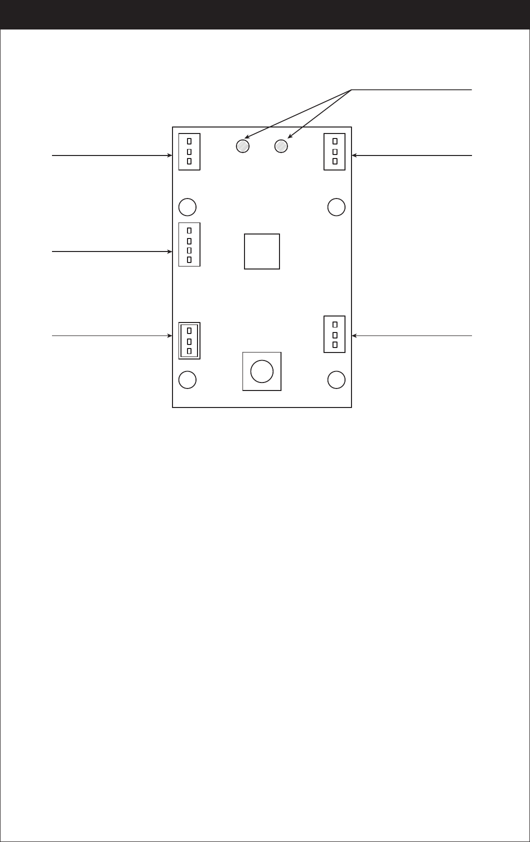
Receiver board wire diagram
www.udirc.com
Front
Rear
Positive/ Negative wire pad
Front B LED board socket
Rear A LED board socket
Front A LED board socket
Camera board socket
Rear B LED board socket
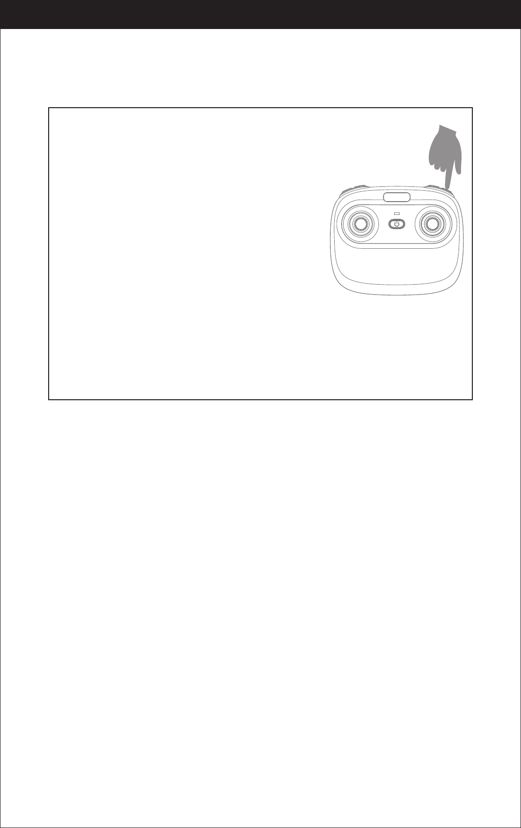
11
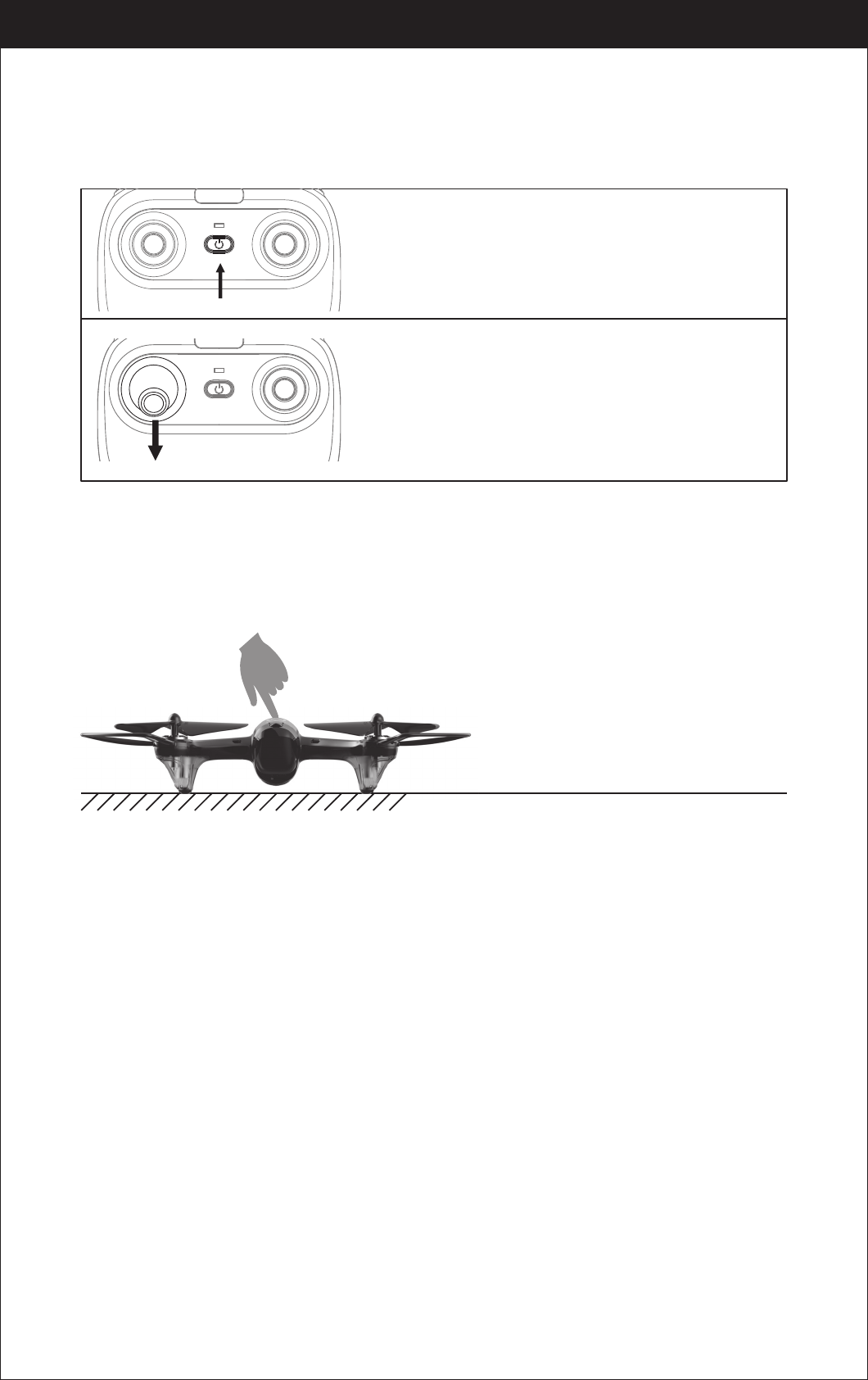
Flight Instruction
Frequency Pairing
Turn on the transmitter switch and the
power indicator light flashes rapidly.
Pull the Left Stick all the way down to the lowest
position and then release. The Left Stick will back
to the middle position automatically. The power
indicator light flashes slowly, which indicates the
transmitter is ready for frequency pairing.
Press the drone power button for about 2 seconds to power on, the LED indicator
changes from flashing to solid light, the drone is pairing successfully and ready
to control.( Transmitter beep sound)
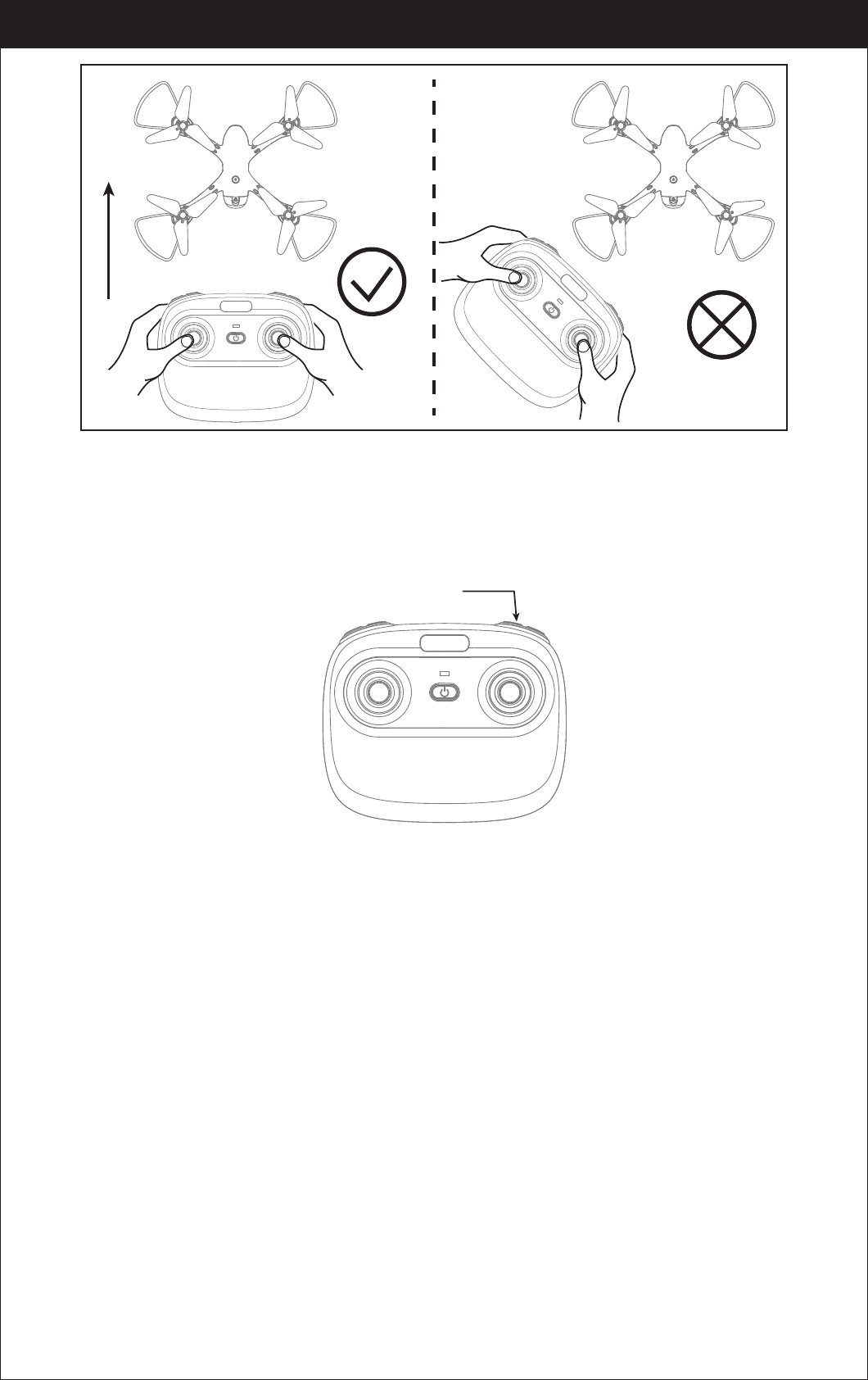
It’s a must to put the drone on
the horizontal position !!!
www.udirc.com
Power switch (Press down)
12
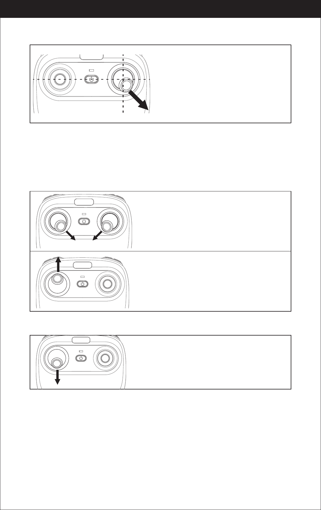
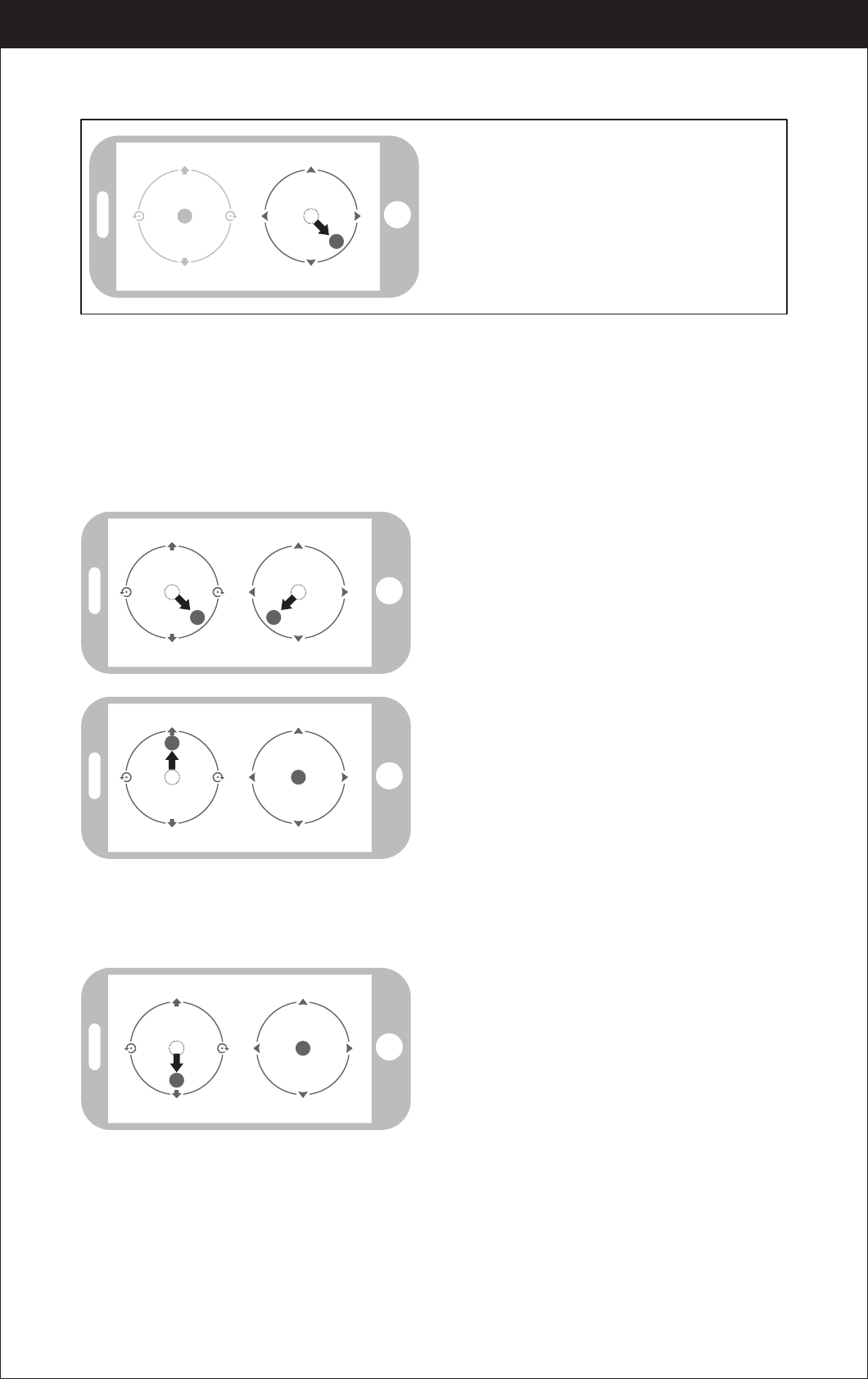
Drone calibration(After pairing successful)
Push the right stick as picture shown.
(Don’t move the left stick before successful
calibration), the drone body light will flash 3
times, indicating that the drone is calibrating.
After successful calibration, the drone lights
will become solid and ready to fly.
Tips: Crashing the drone may cause it imbalanced beyond the level that can
be adjusted by the trimmer button. If this occurs, you can re-pairing &
re-calibrate.
Repeat above steps several times to practice.
Push the left stick up slowly, the drone will take off.
Move the left stick and right stick at the same
time 45 degree inward.(This operation is used
for starting/locking the motors. When the
motors are working, it could be used to stop the
motors urgently.)
Take Off
Landing
Pull down the left stick to its lowest position
slowly to land the drone on the ground.
www.udirc.com
13
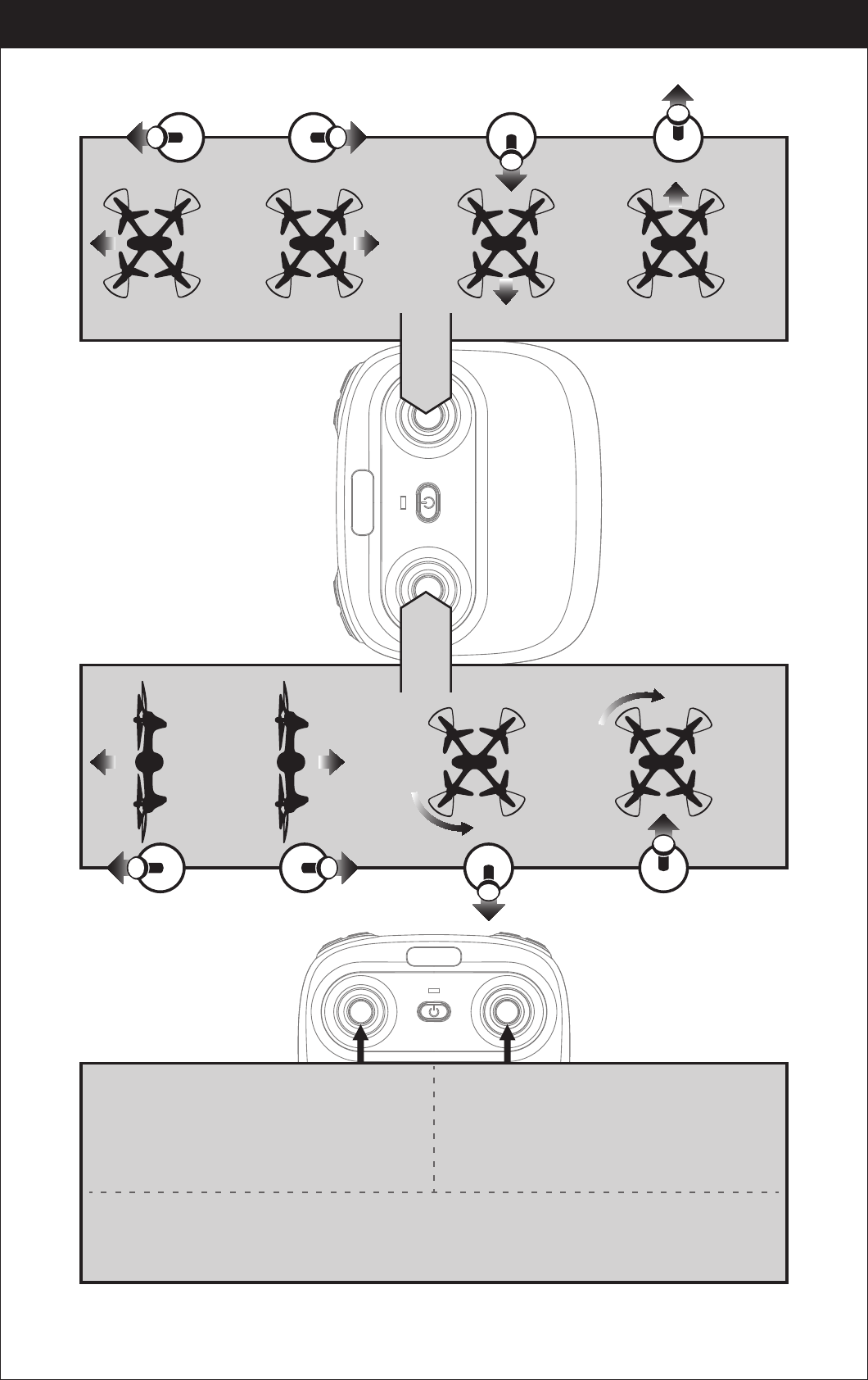
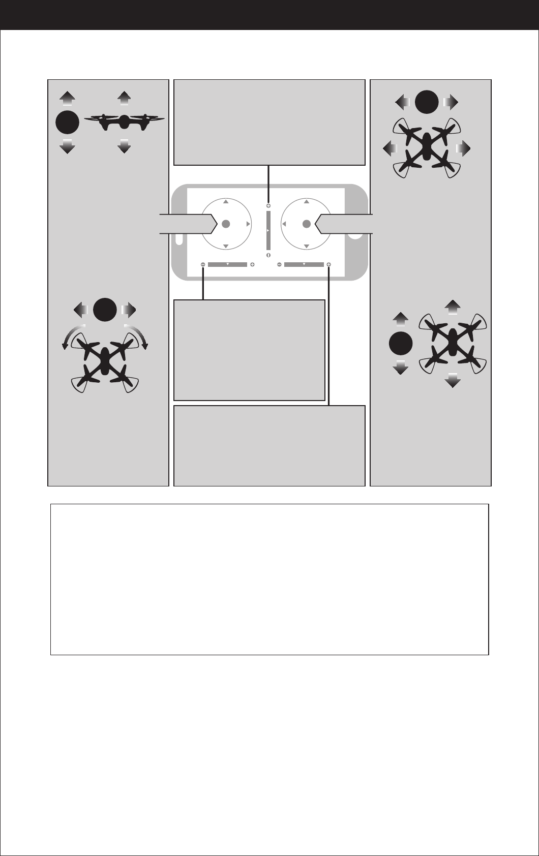
Flying Control
Left and right turning trimmer
When take off, if the drone head rotates to left,then press down the trimmer button and push the left
stick to right. Otherwise push to left.
Forward and backward trimmer
When take off, if the drone tilts forward, press
down the trimmer button, and push the right
stick backwards. Otherwise push forwards.
Left and right side flying trimmer
When take off, if the drone tilts to left, then press
down the trimmer button and push the right stick
backwards to adjust. Otherwise push forwards.
Trimmer mode
Left Stick
Move the stick to the left,
then the drone turns to left.
Move the stick to the right,
then the drone turns to right.
Push up the stick, then
the drone flies up.
Pull down the stick, then
the drone goes down.
Right Stick
Push up the stick, then
the drone flies forward.
Pull down the stick,
then the drone
goes backward.
Move the stick to the left,
then the drone turns to left.
Move the stick to the right,
then the drone turns to right.
www.udirc.com
14
One button take off/Landing、Emergency stop
Functions Introduction
One Button Take Off
After frequency pairing successful or motors activated, press the Take Off /
Landing / Emergency Stop Button, the drone will fly up automatically and
keep flying at an altitude of 1.2 meters approximately.
One Button Landing
When flying, press the Take Off / Landing / Emergency
Stop Button once shortly, and the drone will land on the
ground automatically.
(When using this function, you can not touch the left
stick, if not, then the function will fail)
Emergency Stop
When the drone in emergency situation and going to hit the walking people or obstacle
etc., press the Take Off / Landing / Emergency Stop Button immediately and hold it for
more than 1s,the propellers will stop immediately.
Tip: Do not use the emergency stop function unless in emergency situation.
The drone will fall down suddenly after all propellers stop.
www.udirc.com
Altitude Hold Mode
Note: If the propeller is deformed or damaged, Altitude Hold Mode will fail.
If the atmospheric pressure is instability or typhoon weather, Altitude
Hold Mode will not work well.
Intelligent flight control system calculates the hovering position, more stable
control feature, makes it easier for beginners to control. Release the stick, the
drone will keep hovering automatically to enable single hand operation and more
clearly aerial photography.

15
www.udirc.com
Press down this button,then it will sound “ di”, it means low speed mode “L”;
when it sounds “ di.di”,means medium speed “M”; and sounds “ di.di.di” means
high speed mode “H”.(Low speed default)
High / Medium/Low Speed Mode Switch
1. Low Speed Mode(Mode 1)
Low Speed Mode is suitable for beginner.
2. Medium speed Mode(Mode 2)
Medium Speed Mode is suitable for skillful pilots
to play in the gentle breeze.
3. High Speed Mode(Mode 3)
High Speed Mode is suitable for expert to
experience aerial stunt outdoor.
The default setting is NOT Heading hold Mode.
Drones generally have a front and rear indicated by LED lights or colored
propellers. By default, the users are required to tell the front and the rear of the
drone when flying. Under heading hold mode, the users can operate the drone
without worrying about the orientation (left is left and right is right all the time,
regardless of where your drone is pointing at).Heading Hold Mode is designed for
beginners and the users who fly the drone in daylight or at a far distance or
difficult to identify the drone orientation.
Heading Hold Mode
You are allowed to activate the heading hold mode function before taking off or in
flight. Fly under heading hold mode, you’re required to ensure the drone front
direction aligned with your front direction, DO NOT change your direction of your
transmitter and keep it fly in front of you all the time.(See below picture)
WARNING: DO NOT USE HEADING HOLD MODE BEFORE YOU ARE SURE THAT
THE DRONE'S FRONT IS YOUR FRONT. OTHERWISE, IT MIGHT BE
OUT OF CONTROL OR FLY AWAY.
High / Medium/Low Speed
button(press down)
16
www.udirc.com
*Press the Heading Hold Mode button. The drone’s LED lights will flash
alternatively, indicating that the drone has entered Heading Hold Mode.
To turn off Heading Hold Mode, press the Heading Hold Mode button again.
The drone’s LED lights turn solid, indicating that Heading Hold Mode is off.
Low Battery Alarm
When the transmitter in low battery, the transmitter will beep “di...di...di...” to
remind the user to land the drone to replace the batteries as soon as possible.
Or the drone may be out of control.
When the drone in low battery, the transmitter will beep” di.di.di...” constantly to
remind the user to land the drone as soon as possible.
Out of Range Alarm
When the drone is going to fly out of the max remote control distance, the
transmitter will beep “didi...didi...didi...” to alarm the user to fly back the drone
immediately. Or the drone may be out of control and fly away.
Heading Hold Mode
Front
Rear
Left Right
Front
Rear
Left Right
17
www.udirc.com
Download and Install the APP: Flyingsee
The APP is suitable for mobile phone with iOS and Android system, please
download from the mobile phone software store:
1. For mobile phone with iOS system, please search Flyingsee
in APP Store.
2. For mobile phone with Android system, please search
Flyingsee in Google Play.
3. Scan the QR code on the right or the QR code in the box to
download Flyingsee.
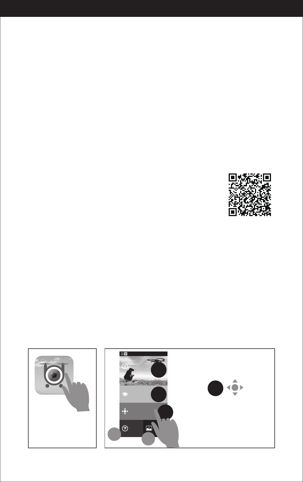
To know your APP
Motors Stuck Protection
1. When the propellers get stuck, then the drone LED will flash quickly and
activate stuck protection function and the motors stop running.
2. Pull down the left stick to the lowest position, the drone LED will get a solid
light and stuck protection will be released and the drone can fly again.
Smartphone control steps for drone
Pairing your Device with Drone
2. Enter your device’s set up screen, turn on Wi-Fi (WLAN) and choose
udirc-***,.Return to main screen after successful connection.
1. Install the Li-po battery into the drone and power on the drone. Put the drone
on a flat surface in a horizontal position. ( Very Important)
3. 4.
Tap this icon to
open the APP.
Flyingsee
3
Learn the operation
of drone
Remote control interface
Media
Help
Explore UDIRC Drone
HOME
1
2
3
45
Select to enter
the remote control interface for
real time transmission.
18
www.udirc.com
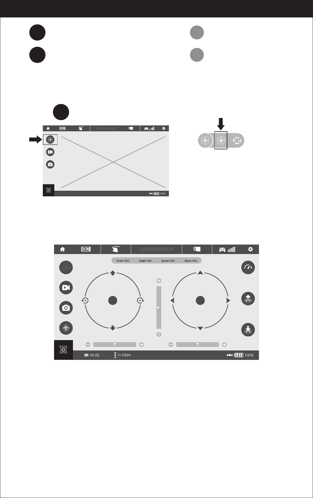
Learn all the APP icons first
Virtual Control Interface
Select to enter the remote control interface for real time transmission.
Go to UDIRC official website for more
information about our products.
Download the manual and learn how to
fly the drone properly.
Help & Tips.
View your photos or videos.
1
2
3
4
5
pop-up window. Enter to the virtual
remote interface , the drone body
LED lights change from flashing to
solid, indicating that the paring is
successful and the drone is ready
for fly.
Tap the icon in
Real time Transmission Interface
Pairing
19
www.udirc.com
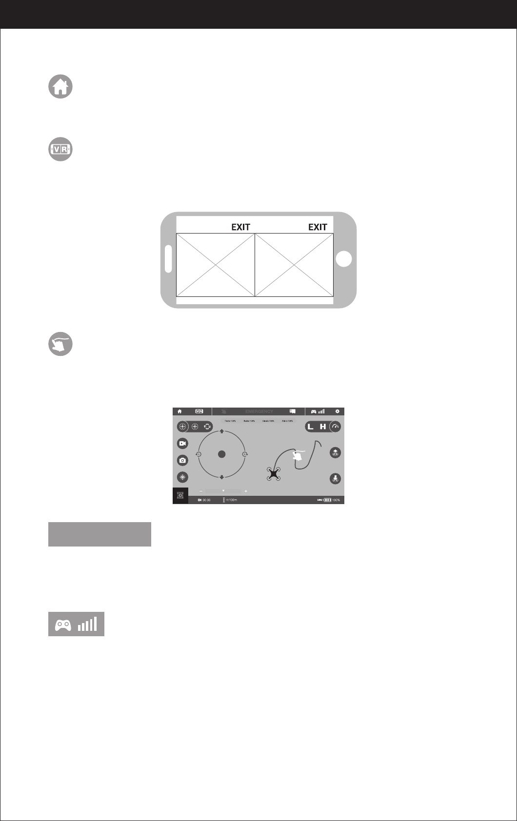
Introduction Of The APP Icons
Home Page Icon
Tap to go back to the Home Page.
Tap to enter virtual reality mode to experience first person view(only available
when using a VR headset). Tap red icon “EXIT” to exit from virtual reality mode.
Virtual Reality Mode
Tap this icon to go to the drawing interface, draw a flight route on the right area.
The drone will fly according to the flight route. Tap again to exit from Flight Route
Setting Mode.
Flight Route Setting Mode
EMERGENCY
This icon is red by default. Tap and the propellers will stop immediately .
The drone will fall straight to the ground.
EMERGENCY STOP
To show the drone’s wifi signal strength.
Remote Control Signal
image image
20
www.udirc.com
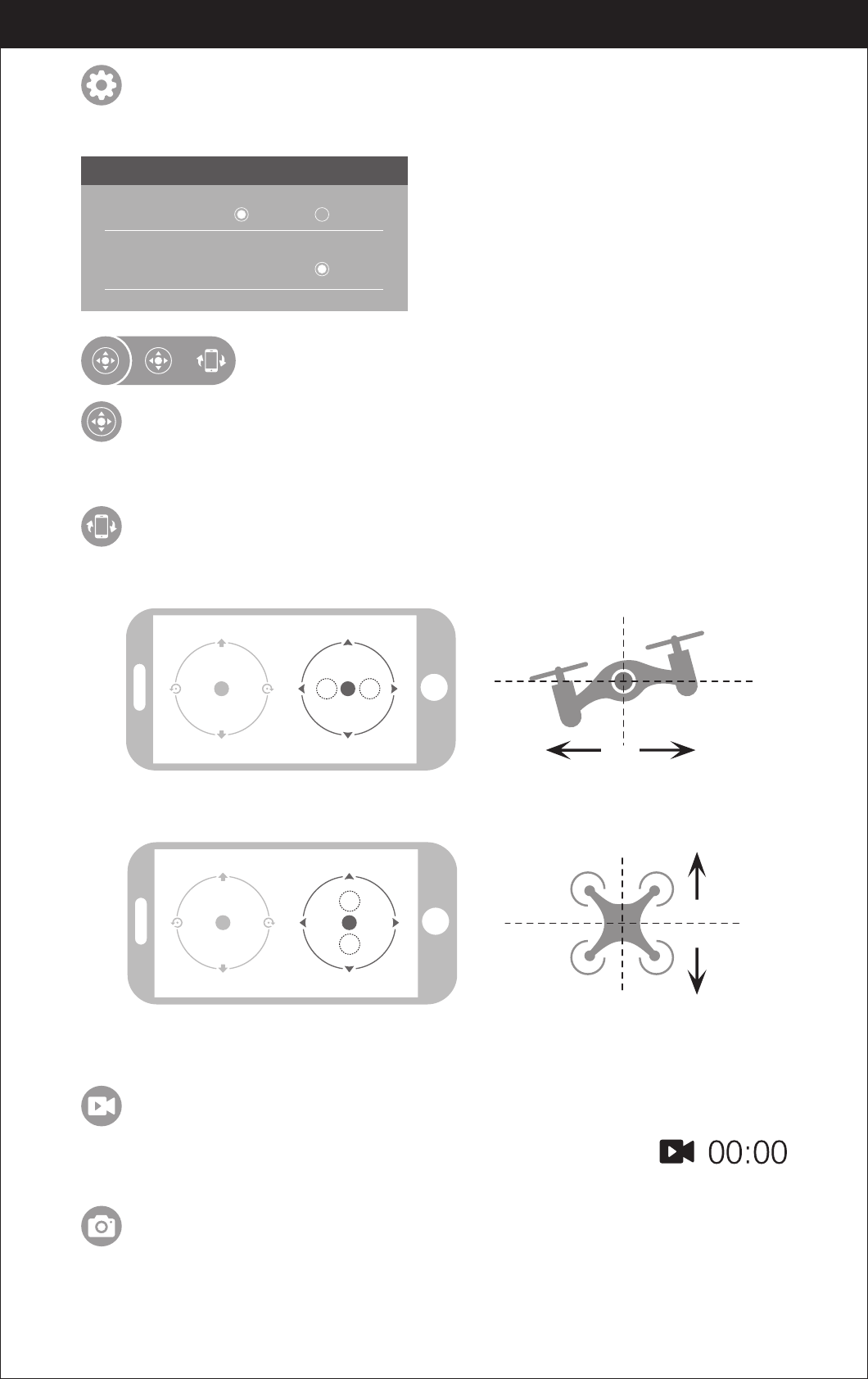
Tap to take a photo.
Take Photo
Tap to record video. The recording time will display at the
bottom of the screen. Tap again to stop recording.
Record Video
Tap this icon to set parameters. Tap again to exit.
Tap “Save” to save trimmer setting.
Tap”Reset” to factory reset.
Pictures transmission resolution
Setting
SETTING
Trimming Save Reset
Transmission quality 480P
If the mobile phone tilts to forward / backward,
the Right Ball will roll forward / backward enabling the drone to fly forward / backward.
Remote Control mode selection
Virtual control stick
The virtual remote controller is hidden by default. Tap the icon to display
the virtual remote controller.
Tap this icon to enter Gravity Induction Mode. Tilt the phone to fly left / right
and forward / backward. Tap again to exit from Gravity Induction Mode.
Gravity Induction Mode
If the mobile phone tilts to the left / right,
the Right Ball will move accordingly enabling the drone to fly left / right.
21
www.udirc.com
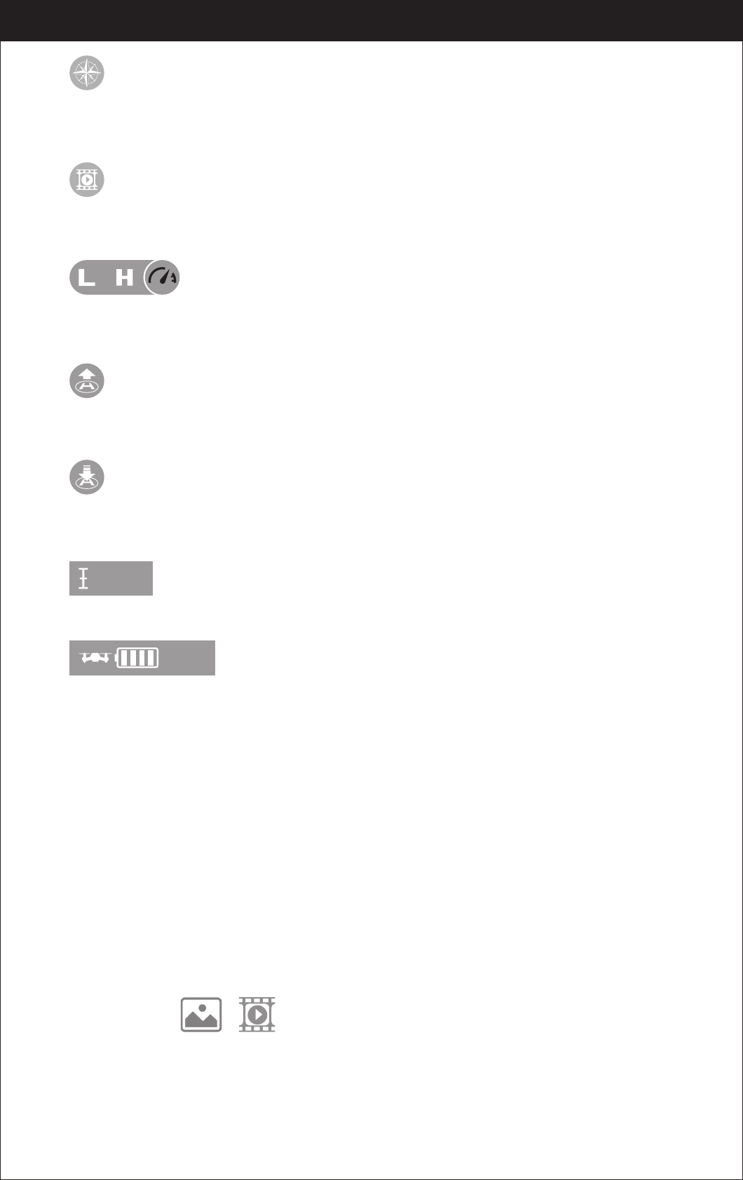
H:0.1m
100%
Click on this icon again and the icon turns red, the drone will fly down slowly and
land on the ground. All propellers also will stop running.
The real time flying altitude(Based on the calibration altitude)
When the drone battery capacity left around 15%, the phone will vibrate to alarm
that the battery is going to run out and you need to fly back and replace the battery.
One Button Landing
Flying Altitude
Drone battery status icon
Click on this icon and it turns red shortly. The drone will fly up automatically and
stay flying at an altitude of 1.2 meters.
One Button Take Off
Click on this icon to view or delete the aerial video and photo. Click on the arrow
to exit.
Media
By default, the drone is in Low Speed Mode “L”. Click on “H” to enter High
Speed Mode.
High / Low Speed Mode
Tap and it turns red, indicating that the drones has entered Heading Hold Mode.
Tap again to exit from Heading Hold Mode. The icon turns highlight.
Heading Hold Mode
Display the photos and video
Notice: App must be authorized to access the phone gallery, if not, then may
be unavailable to display the video and photos.
The photos and videos are stored in the phone local gallery,
you can display in the phone directly. You also can display it in the APP through
shortcut icon to enter the media interface.
22
www.udirc.com
APP CALIBRATION( After pairing successful)
Take Off
Move the right ball outward 45 degree
(Do not touch the left ball). The drone body
light will flash 3 times, and then become
solid , indicating calibration is complete
and the drone is ready to be controlled.
Tips: Crashing the drone may cause it to become imbalanced beyond the level
that can be adjusted by the trimmer button. If this occurs, you can do the
connection with Wi-Fi , pairing and calibration again.
Move the left ball up slowly, the drone will
take off.
Move the left ball and right ball at the same
time 45 degrees inward to active the motors.
( This operation is used for starting/locking
the motor. When the motor is working, it
could be used to stop the motor urgently)
Landing
You can repeat above steps to be familiar about the APP interface.
Move the left ball down to the lowest
position. The drone will land.
23
www.udirc.com
Notice:
1. If you can not find the Wi-Fi signal to connect, turn off Wi-Fi
and turn on again to search and connect.
2. The available Wi-Fi control radius/distance is 40m, please
control the drone within this range.
3. When alternating control from mobile phone to transmitter,
the transmitter left stick must be in the center position, or
exit from the APP. If not then you can not control the drone
alternately.
Left Stick Right Stick
To fly up or down:
Move the Left Ball up to fly
up and move the Left Ball
down to fly back down.
The drone will continue
flying at appointed
altitude after release
the ball.
To fly right side or
left side:
Move the Right Ball to the
left to fly the drone to the
left side, and move the
Right Ball to the right to
fly the drone to the right
side.
If the drone tilts forward or backward
Click the “-”of the Forward /Backward Trim
to adjust the drone. If the drone tilts forward.
Click the “+” to adjust the drone if the drone
tilts backward.
If the drone rotates to left
or right
Click the ”+” of the Left/Right
Rudder Trim If the drone rotates
left. Click the “-”if the drone
rotates right.
If the drone tilts to the left or right
Click the “+” of the left /Right Flying Trim
if the drone tilts to the left Click the “-”to
adjust the drone if the drones tilts to the
right.
To fly forward or
backward:
Move the Right Ball up to
fly the drone forward, and
move the Right Ball down
to fly the drone backwards.
To rotate left or right:
Move the Left Ball to the
left to rotate the drone to
the left. Move the Left Ball
to the right to rotate the
drone to the right.
Flying Control
24
www.udirc.com
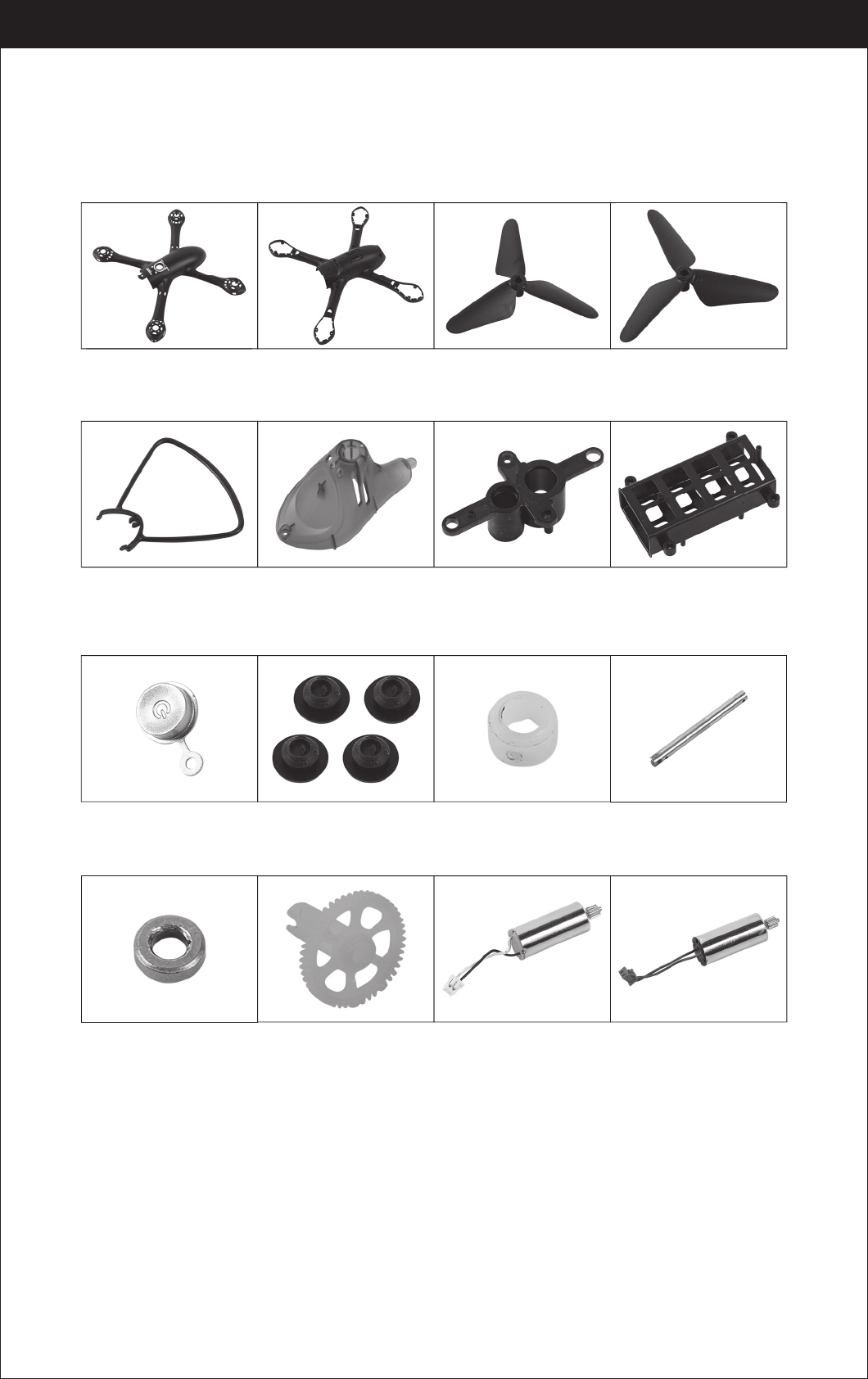
U47-13
Copper ring
U47-14
Transmission gear
U47-15
A propeller motor
( Black white wire/
white connector)
U47-16
B propeller motor
( Red blue wire/
red connector)
Spare Parts
For convenience, the spare parts are listed for you to choose, which can be
purchased from the local seller.
U47-01
Drone Housing Cover
U47-02
Drone Bottom Housing
U47-03
A Propeller
U47-04
B Propeller
U47-05
Propeller Guard
U47-06
Landing gear
LED lampshade
U47-07
Motor Holder
U47-08
Receiver board holder
U47-09
Power Button
U47-10
Cushion
U47-11
Steel pipe fixings
U47-12
Spindle steel pipe
25
www.udirc.com
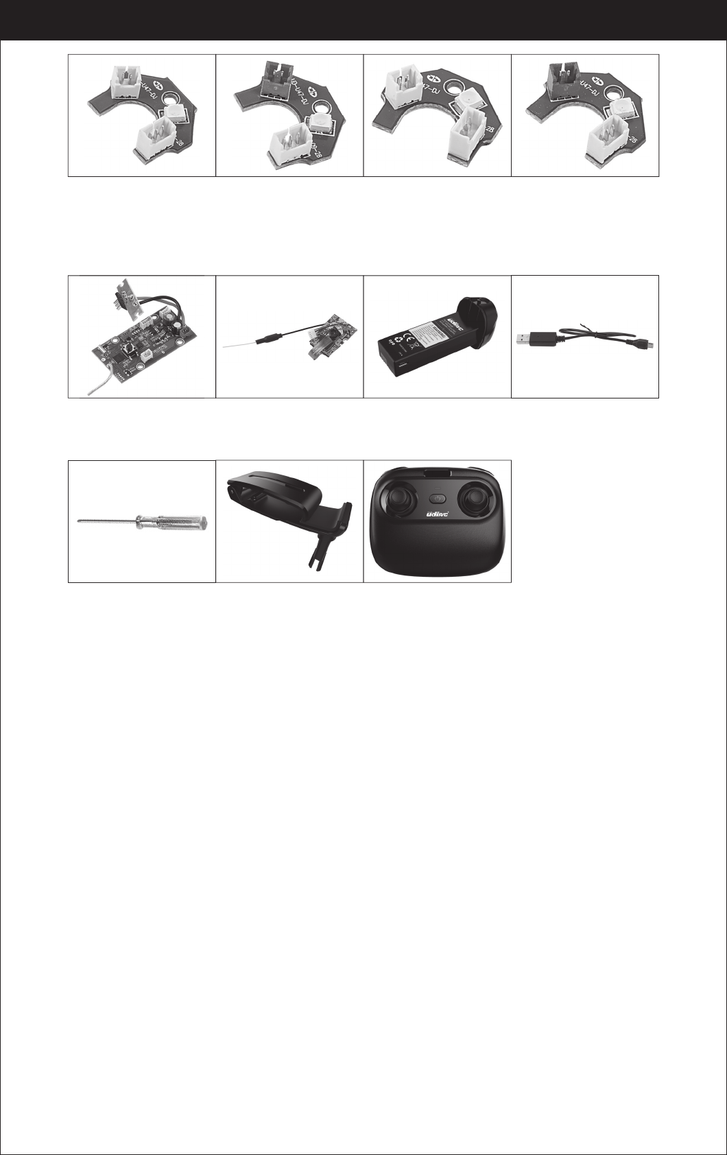
U47-17
Front A LED board
(Green LED/
white connector)
U47-18
Front B LED board
(Green LED/
red connector)
U47-19
Rear A LED board
(Red LED/
white connector)
U47-20
Rear B LED board
(Red LED/
red connector)
U47-21
Receiver board
U47-22
Camera board
U47-23
Drone battery
U47-24
USB cable
U47-25
Screw driver
U47-26
smart phone holder
U47-27
Transmitter
Important Notice
Our company's products are improving all the time, design and
specifications are subject to change without notice.
All the information in this manual has been carefully checked to ensure
accuracy, if any printing errors, our company reserve the final
interpretation right.
26
www.udirc.com
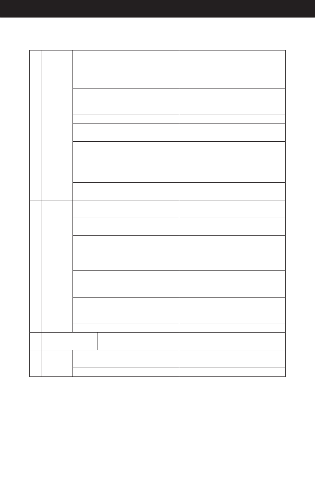
The
controller
indicator
light is off.
The drone
is under-
powered
or can not
fly.
The drone
could not
hover and
tilts to one
side.
1
3
4
Problem Problem Cause SolutionNo.
1. Low battery. 1. Replace the controller battery.
2. The batteries are incorrectly positioned. 2. Install the batteries following the polarity
indicators.
3. Poor Contact. 3. Clean between the battery and the battery
contacts.
1. Indicator light is off. 1. The same as above.
2. There is an interfering signal nearby.
2. Restart the drone and power on the controller.
3. Improper operation. 3. Operate the drone step by step in
accordance with the user manual.
4. The electronic component is damaged for
fiercely crash.
4. To buy spare parts from local seller and
replace damaged parts.
1. The propeller is seriously deformed. 1. Replace the propeller.
2. Low battery. 2. Recharge the drone battery.
3. Incorrect installation of propeller. 3. Install the propeller in accordance with the
user manual.
2. The propeller is seriously deformed. 2. Replace the propeller.
3. The motor holder is deformed after violent
crash. 3. Replace the motor holder parts.
1. Improper Calibration. 1. Please refer to the Calibration Instruction.
4. The gyroscope did not reset after a serious
crash.
4. Put the drone on the flat ground for about
10s or restart the drone to calibrate again.
Failed to
pair the
drone with
the
controller.
2
The drone
indicator
light is off.
Could not
see the
picture.
5
6
1. Low battery. 1. Recharge the drone battery.
5. Motor is damaged. 5. Replace the motor.
2. The battery is expired or over discharge
protection.
2. Buy a new battery from local seller to
replace the battery or charge the battery in
accordance with the use manual.
3. Poor contact. 3. Connect and disconnect the battery.
1. There is an interfering signal nearby. 1. Practice and read the cellphone controlling
instruction carefully.
2. Camera is damaged. 2. Replace Camera.
Hard to control by
cellphone.
7
Not experienced enough. Practice and read the cellphone controlling
instruction carefully.
Can’t
altitude
hold.
8
1. The propeller deformed seriously. 1. Replace propeller.
2. The motor is damaged. 2. Replace the motor.
3. Atmospheric pressure is not stable.
3. Refer the altitude hold mode of use manual .
Troubleshooting

27
www.udirc.com
MADE IN CHINA
FCC Note
This equipment has been tested and found to comply with the limits for a Class B
digital device, pursuant to Part 15 of the FCC Rules. These limits are designed to
provide reasonable protection against harmful interference in a residential
installation. This equipment generates uses and can radiate radio frequency
energy and, if not installed and used in accordance with the instructions, may
cause harmful interference to radio communications. However, there is no
guarantee that interference will not occur in a particular installation. If this
equipment does cause harmful interference to radio or television reception, which
can be determined by turning the equipment off and on, the user is encouraged to
try to correct the interference by one or more of the following measures:
● Reorient or relocate the receiving a ntenna.
● Increase the separation between the equipment and receiver.
● Connect the equipment into an outlet on a circuit different from that to which
the receiver is connected.
WARNING: Changes or modifications not expressly approved by the party
responsible for compliance could void the user's authority to
operate the equipment.
This device complies with Part 15 of the FCC Rules. Operation is subject to the
following two conditions:
(1) This device may not cause harmful interference.
(2) This device must accept any interference received, including interference that
may cause undesired operation.
The equipment may generate or use radio frequency energy. Changes or
modifications to this equipment may cause harmful interference unless the
modifications are expressly approved in the instruction manual. Modifications not
authorized by the manufacturer may void user’s authority to operate this device.
FCC Notice:
The device has been evaluated to meet general RF exposure requirement.
The device can be used in portable exposure condition with out restriction.
FCC Radiation Exposure Statement