Cherry Europe AFIS5001 Autarker Funkschalter - Evaluation-Kit User Manual 6442008 01 US Funkschalter CD
Cherry GmbH Autarker Funkschalter - Evaluation-Kit 6442008 01 US Funkschalter CD
Contents
- 1. UserManual.pdf
- 2. UserManualSafetyStatement.pdf
UserManual.pdf
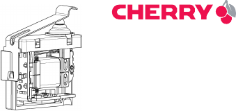
Energy harvesting
wireless switch
Evaluation kit
Comfort/Engineer
Operating manual
6442008-01 US, Dez 2012
2
Safety guidelines
WARNING: Danger to life
• Do not install this kit as part of a safety-
relevant, life or health preserving facility.
CAUTION: Damage to components of
the evaluation kit due to electrical
discharge
• Observe the ESD protection.
CAUTION: Damage due to liquid in the
components of the evaluation kit
• Prevent liquid from getting inside the
components.
• Do not use solvents such as benzine or
alcohol, or scouring agent and scourers for
cleaning.
3
Contents
1 Area of application.............................................. 4
1.1 Comfort evaluation kit...................................... 5
1.2 Engineer evaluation kit .................................... 6
2 Product description ............................................ 7
2.1 Wireless switch ................................................ 7
2.2 Generator model .............................................. 7
2.3 Receiver ............................................................ 8
2.4 Software............................................................ 8
2.5 Antennas........................................................... 9
2.6 CD...................................................................... 9
3 Installing the USB driver .................................. 10
4 Installing software ............................................ 11
5 Troubleshooting................................................ 13
6 Technical data................................................... 14
7 Engineer receiver interfaces ............................ 16
8 Declaration of conformity................................. 19
9 Disposal............................................................. 19
10 Contact .............................................................. 19
11 General user information ................................. 20
4
1 Area of application
The evaluation kits were designed to show you the
main function and output of the energy harvesting
wireless switch.
The components provided are for testing purposes
and not suitable for using in a serial product, con-
tinuous operation or permanent connection to
other units.
5
1.1 Comfort evaluation kit
The Comfort evaluation kit receiver class 3 was
developed for convenient operation in a compact
design.
As only a small antenna is fitted due to its compact
design, the range is less than with an external
antenna.
The switch signals are displayed on the receiver
stick with LEDs. You can also see the strength of
the signals via software on a computer.
Receiver
Volume model
Wireless
switch
generator stick
6
1.2 Engineer evaluation kit
The engineer evaluation kit receiver class 2 is
designed for optimum output and consists of
several interfaces for the development
environment. It may only be operated by those with
electrical engineering expertise.
To gain direct access to the interfaces, the receiver
consists of a large circuit board without housing.
Several antennas can be connected to the SMA
Wireless
switch
Volume
generator
SMD antenna
Receiver circuit board
USB cable
Dipol antenna
model
7
connection on the circuit board.
See also: 7 "Engineer receiver interfaces".
You can also see the strength of the signals via the
software on a computer. These can be exported for
measuring.
2 Product description
2.1 Wireless switch
The switch contains a generator which converts the
mechanical energy of the probe into electrical
energy. The energy supplies the wireless
electronics and data is transmitted the with
868 MHz (Europe) or 915 MHz (US version).
2.2 Generator model
To show the small size of this part, the evaluation
kit contains a functionless volume model of the
generator.
8
2.3 Receiver
The radio signal is received by the antenna. The
electronics interpret the data and transmit the
information to the hardware and software
interfaces. The information is displayed via LEDs
and the software.
See also: 7 "Engineer receiver interfaces".
2.4 Software
The software on the computer displays the
following data:
You can save up to 10 000 data sets. The data can
be deleted using the "Clear" button and saved as
*.txt files using the "Export" button. The
Name Value
Time stamp Incoming time of the signal
UID Switch ID
State Switch status
Message Signal received
Count Number of signals received
Signal strength Signal strengths received in
dBM and nW/pW
9
communication with individual switches and the
relay function can be deactivated.
2.5 Antennas
The Engineer evaluation kit contains 2 exchange-
able antennas:
• SMD antenna circuit board with SMA connector
• SMA dipole antenna
2.6 CD
The CD contains demonstration software, CAD files
with the dimensions and these operating instruc-
tions.
10
3 Installing the USB driver
System requirements:
Windows XP, Vista or 7, USB 2.0 connection.
1 Copy the "Cherry_EHS-RF_Software" folder from
the CD onto your computer.
2 Connect the receiver.
•Comfort evaluation kit:
Plug the receiver stick into the computer so that
the components (LEDs) can be seen on the cir-
cuit board. Use a USB hub or an extension cable
if necessary.
•Engineer evaluation kit:
Connect the receiver circuit board to the com-
puter using the USB cable provided.
The yellow LED flashes on the receiver.
The device driver installation prompts you to
install the driver software. The drivers for 32- and
64-bit variants are located in the "Cherry_EHS-
RF_Software/Driver" folder.
3 Follow the instructions in the installation wiz-
ard. If problems arise, you will find detailed video
instructions on the CD.
The yellow LED lights up on the receiver.
11
4 Press and hold down the button on the wireless
switch.
The green LED lights up.
5 Release the button again on the wireless switch.
The blue LED lights up.
4 Installing software
Requirement: The receiver is connected and the
USB driver is installed (see 3 "Installing the USB
driver"). The "Cherry_EHS-RF_Software" folder is
on your computer.
1 Link the "RadioMonitor.exe" file on your desktop
for later access.
2 Start the link to "RadioMonitor.exe".
If "dotNET Framework V4" is not installed on your
computer you will receive a message. Load
"dotNET Framework V4" from the CD and install
it.
The "Set_Check_COM" window appears.
3 Select the COM port of the receiver from the list.
(This is usually the one with the highest number.)
12
4 Press the wireless switch.
When you have selected the COM port of the
receiver, the switch position is shown on the
switch diagram.
The "Next >" button is active.
•If the button is not active:
Repeat the procedure by selecting another COM
port from the list until you have found the con-
nection for the receiver.
5 Click on the Next >button.
The "RadioMonitor" window appears.
6 Press the switch.
The status of the switch is displayed by the switch
diagram, the two round areas and the status
display in the table. (Green = Status 0 = pressed.
Blue = Status 1 = released.)
13
5 Troubleshooting
•The yellow LED on the receiver is not flashing:
– Use another USB port on the computer/laptop.
•The reception is poor:
– Remove any metal objects from the transmis-
sion area.
– Do not place transmitters and receivers directly
on reflecting objects or walls.
– Switch off any possible sources of radio interfer-
ence, such as electrical appliances or machines.
– Adjust the position of the antenna.
– Shorten the distance between transmitter and
receiver.
– Do not keep pressing the switch in quick succes-
sion.
•The same switching status is received several
times in a row (OO or 11):
– Do not keep pressing the switch in quick succes-
sion.

14
6 Technical data
Name Value
Storage and operat-
ing temperature
0 °C ... +50 °C
Permissible relative
humidity
10 ... 90 %, noncondensing
Supply voltage
receiver
5.0 V/DC ±5 % SELV
Receiver current
consumption
Max. 100 mA
Receiver connection
to computer
USB 2.0, max. 3 m cable
Frequency EU (AFIK-1xxx): 868 MHz
US (AFIK5xxx): 915 MHz
Modulation FM
Transmission range Open field: typ. 300 m,
in buildings: typ. 30 m
Transmitter power
level
At antenna connection:
10 dBm,
on the antenna:
max 9 dBm

15
Damping receiver SMD circuit board
antenna: typ. 5 dB
SMA dipole antenna:
typ. 1 dB
Receiver signal-to-
noise ratio
Min. 6 dB
Analog interfaces 0 ... 5 V (USB input volt-
age), 10 bit resolution,
max. output current 5 mA,
short-circuit protected
Digital interfaces 5 V TTL, max. continuous
current 5 mA, short-cir-
cuit protected
Name Value
16
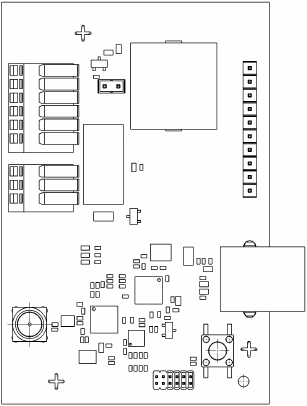
7 Engineer receiver
interfaces
햳
햴
햵햶
햷
햸햹
햺
햻
햲
햽
1
1
1

17
No. Item Description*
햲1 Analog 1: dimming
2 Analog 4: signal strength dBm
3 Digital 1: switch position
4 Digital 2: weak signal
5 Digital 3: interrupt for valid data
6 COM 1: interrupt for invalid data
햳Relay, 12 V/DC, 1 A
1A
2COM
3B
햴Buzzer, 4 kHz
햵Jumper set: buzzer on
햶1 Analog 2: dimming inverted
2 Analog 3: reserved
3 LED: LED status

18
* You will find detailed comments on the CD.
4 Digital 4: dimmer pulse width modu-
lation (PWM)
5 Digital 5: reserved
6 Digital 6: reserved
7 COM 2: interrupt for valid data (RF)
8 Supply voltage (VCC)
9 Earth (GND)
10 Digital 7: ATA
햷LED red
햸Status LEDs: blue, yellow, green
햹USB port
햺Antenna connection SMA
햻Reset button
햽Internal programming interface for
CHERRY
No. Item Description*

19
8 Declaration of conformity
These components are CE certified
and comply with the EN 300-220
guidelines. They were made and
tested for use in Europe and USA in
accordance with the FCC Part 15.249 and 15B.
Observe the local regulations before using in other
countries.
9 Disposal
Dispose of the used components of the
evaluation kit at an official collection
point for electronic waste or at your
local dealer.
10 Contact
ZF Friedrichshafen AG
Electronic Systems
Cherrystraße
91275 Auerbach, Germany
Internet: www.cherryswitches.com
E-mail: info@cherryswitches.com
20
11 General user
information
We reserve the right to make technical modifica-
tions which serve the development of our products.
Improper use and storage can lead to faults and
damage to the product.
The warranty expires completely once unautho-
rized modifications to the product have been car-
ried out. Do not carry out any unauthorized repairs
and do not open up the product. These instructions
are only valid for the supplied product.
The warranty for this product is for commercial
customers for one year from date of purchase. Lia-
bility for financial damages and defects is excluded.