Chevrolet 2000 Cisco Nexus Series Hardware Installation Guide User Manual To The 20bd6b29 7b30 40b7 B8a5 9436fc4cb7df
User Manual: Chevrolet 2000 to the manual
Open the PDF directly: View PDF ![]() .
.
Page Count: 190 [warning: Documents this large are best viewed by clicking the View PDF Link!]
- Cisco Nexus 2000 Series Hardware Installation Guide
- Contents
- Audience
- Organization
- Conventions
- Related Documentation
- Obtaining Documentation and Submitting a Service Request
- Using a Fabric Extender with a Cisco Nexus 5000 Series or Cisco Nexus 6000 Series Switch
- Using a Fabric Extender with a Cisco Nexus 7000 Series Switch
- Using a Fabric Extender with a Cisco Nexus 9000 Series Switch
- Installing a Cisco Nexus Fabric Extender
- Preparing for Installation
- Installing the Cisco Nexus Fabric Extender Chassis in a Cabinet or Rack
- Grounding the System
- Grounding the Chassis
- Starting the Cisco Nexus Fabric Extender
- Removing and Installing Components
- Repacking the Cisco Nexus Fabric Extender for Return Shipment
- Connecting a Cisco Nexus Fabric Extender
- Cabinet and Rack Installation
- Technical Specifications
- Cable and Port Specifications
- Troubleshooting Hardware Components
- LEDs
- Accessory Kit
- Site Preparation and Maintenance Records

THE SPECIFICATIONS AND INFORMATION REGARDING THE PRODUCTS IN THIS MANUAL ARE SUBJECT TO CHANGE WITHOUT NOTICE. ALL
STATEMENTS, INFORMATION, AND RECOMMENDATIONS IN THIS MANUAL ARE BELIEVED TO BE ACCURATE BUT ARE PRESENTED WITHOUT
WARRANTY OF ANY KIND, EXPRESS OR IMPLIED. USERS MUST TAKE FULL RESPONSIBILITY FOR THEIR APPLICATION OF ANY PRODUCTS.
THE SOFTWARE LICENSE AND LIMITED WARRANTY FOR THE ACCOMPANYING PRODUCT ARE SET FORTH IN THE INFORMATION PACKET THAT
SHIPPED WITH THE PRODUCT AND ARE INCORPORATED HEREIN BY THIS REFERENCE. IF YOU ARE UNABLE TO LOCATE THE SOFTWARE LICENSE
OR LIMITED WARRANTY, CONTACT YOUR CISCO REPRESENTATIVE FOR A COPY.
The following information is for FCC compliance of Class A devices: This equipment has been tested and found to comply with the limits for a Class A digital device, pursuant
to part 15 of the FCC rules. These limits are designed to provide reasonable protection against harmful interference when the equipment is operated in a commercial
environment. This equipment generates, uses, and can radiate radio-frequency energy and, if not installed and used in accordance with the instruction manual, may cause
harmful interference to radio communications. Operation of this equipment in a residential area is likely to cause harmful interference, in which case users will be required
to correct the interference at their own expense.
The following information is for FCC compliance of Class B devices: The equipment described in this manual generates and may radiate radio-frequency energy. If it is not
installed in accordance with Cisco’s installation instructions, it may cause interference with radio and television reception. This equipment has been tested and found to
comply with the limits for a Class B digital device in accordance with the specifications in part 15 of the FCC rules. These specifications are designed to provide reasonable
protection against such interference in a residential installation. However, there is no guarantee that interference will not occur in a particular installation.
Modifying the equipment without Cisco’s written authorization may result in the equipment no longer complying with FCC requirements for Class A or Class B digital
devices. In that event, your right to use the equipment may be limited by FCC regulations, and you may be required to correct any interference to radio or television
communications at your own expense.
You can determine whether your equipment is causing interference by turning it off. If the interference stops, it was probably caused by the Cisco equipment or one of its
peripheral devices. If the equipment causes interference to radio or television reception, try to correct the interference by using one or more of the following measures:
• Turn the television or radio antenna until the interference stops.
• Move the equipment to one side or the other of the television or radio.
• Move the equipment farther away from the television or radio.
• Plug the equipment into an outlet that is on a different circuit from the television or radio. (That is, make certain the equipment and the television or radio are on circuits
controlled by different circuit breakers or fuses.)
Modifications to this product not authorized by Cisco Systems, Inc. could void the FCC approval and negate your authority to operate the product.
The Cisco implementation of TCP header compression is an adaptation of a program developed by the University of California, Berkeley (UCB) as part of UCB’s public
domain version of the UNIX operating system. All rights reserved. Copyright © 1981, Regents of the University of California.
NOTWITHSTANDING ANY OTHER WARRANTY HEREIN, ALL DOCUMENT FILES AND SOFTWARE OF THESE SUPPLIERS ARE PROVIDED “AS IS” WITH
ALL FAULTS. CISCO AND THE ABOVE-NAMED SUPPLIERS DISCLAIM ALL WARRANTIES, EXPRESSED OR IMPLIED, INCLUDING, WITHOUT
LIMITATION, THOSE OF MERCHANTABILITY, FITNESS FOR A PARTICULAR PURPOSE AND NONINFRINGEMENT OR ARISING FROM A COURSE OF
DEALING, USAGE, OR TRADE PRACTICE.
IN NO EVENT SHALL CISCO OR ITS SUPPLIERS BE LIABLE FOR ANY INDIRECT, SPECIAL, CONSEQUENTIAL, OR INCIDENTAL DAMAGES, INCLUDING,
WITHOUT LIMITATION, LOST PROFITS OR LOSS OR DAMAGE TO DATA ARISING OUT OF THE USE OR INABILITY TO USE THIS MANUAL, EVEN IF CISCO
OR ITS SUPPLIERS HAVE BEEN ADVISED OF THE POSSIBILITY OF SUCH DAMAGES.
Cisco and the Cisco logo are trademarks or registered trademarks of Cisco and/or its affiliates in the U.S. and other countries. To view a list of Cisco trademarks, go to this
URL: www.cisco.com/go/trademarks. Third-party trademarks mentioned are the property of their respective owners. The use of the word partner does not imply a partnership
relationship between Cisco and any other company. (1110R)
Any Internet Protocol (IP) addresses used in this document are not intended to be actual addresses. Any examples, command display output, and figures included in the
document are shown for illustrative purposes only. Any use of actual IP addresses in illustrative content is unintentional and coincidental.
Cisco Nexus 2000 Series Fabric Extender
© 2010-2015 Cisco Systems, Inc. All rights reserved.

iii
Cisco Nexus 2000 Series Hardware Installation Guide
CONTENTS
Preface ix
Audience ix
Organization ix
Conventions x
Related Documentation xvi
Obtaining Documentation and Submitting a Service Request xvii
CHAPTER
1Using a Fabric Extender with a Cisco Nexus 5000 Series or Cisco Nexus 6000 Series Switch 1-1
Information About Using a Fabric Extender with a Cisco Nexus Switch 1-1
Cisco Nexus 2300 Series 1-1
Chassis 1-2
Ports 1-5
Power Supplies 1-6
Fans 1-9
Supported Transceivers and Cables 1-10
Cisco Nexus 2248TP-E 1-10
Chassis 1-10
Ports 1-12
Power Supplies 1-12
Fan Trays 1-15
Supported Transceivers and Cables 1-17
Cisco Nexus 2248TP 1-17
Chassis 1-18
Ports 1-19
Power Supplies 1-19
Fan Tray 1-22
Supported Transceivers and Cables 1-24
Cisco Nexus 2248PQ 1-24
Chassis 1-25
Ports 1-25
Power Supplies 1-25
Fan Trays 1-26
Supported SFP+ Transceivers 1-27

Contents
iv
Cisco Nexus 2000 Series Hardware Installation Guide
Cisco Nexus 2232TM-10GE, Cisco Nexus N2K-C2232TM-E-10GE 1-27
Chassis 1-27
Ports 1-29
Power Supplies 1-30
Fan Trays 1-31
Supported Transceivers and Cables 1-32
Cisco Nexus 2224TP 1-32
Chassis 1-33
Ports 1-34
Power Supplies 1-34
Fan Tray 1-35
Supported SFP+ Transceivers 1-36
Cisco Nexus 2148T 1-36
Features 1-36
Chassis 1-36
Ports 1-38
Power Supplies 1-38
Fan Tray 1-39
Supported SFP Transceivers 1-40
CHAPTER
2Using a Fabric Extender with a Cisco Nexus 7000 Series Switch 2-1
Information About Using a Fabric Extender with a Cisco Nexus 7000 Series Switch 2-1
Cisco Nexus 2248TP-E FEX 2-2
Ports for the Cisco Nexus 2248TP-E FEX 2-4
Power Supplies for the Cisco Nexus 2248TP-E FEX 2-4
Fan Tray for the Cisco Nexus 2248TP-E FEX 2-7
Transceivers and Connectors Supported by the Cisco Nexus 2248TP-E FEX 2-9
Cisco Nexus 2248TP FEX 2-11
Ports for the Cisco Nexus 2248TP FEX 2-13
Power Supplies for the Cisco Nexus 2248TP FEX 2-14
Fan Tray for the Cisco Nexus 2248TP FEX 2-14
Transceivers and Connectors Supported by the Cisco Nexus 2248TP FEX 2-15
Cisco Nexus 2232TM FEX 2-15
Ports for the Cisco Nexus 2232TM FEX 2-17
Power Supplies for the Cisco Nexus 2232TM FEX 2-18
Fan Tray for the Cisco Nexus 2232TM FEX 2-19
Transceivers and Connectors Supported by the Cisco Nexus 2232TM FEX 2-20
Cisco Nexus 2232PP FEX 2-22
Ports for the Cisco Nexus 2232PP FEX 2-24

Contents
v
Cisco Nexus 2000 Series Hardware Installation Guide
Power Supplies for the Cisco Nexus 2232PP FEX 2-25
Fan Tray for the Cisco Nexus 2232PP FEX 2-26
Transceivers Supported by the Cisco Nexus 2232PP FEX 2-26
Cisco Nexus 2224TP FEX 2-27
Ports for the Cisco Nexus 2224TP FEX 2-29
Power Supplies for the Cisco Nexus 2224TP FEX 2-30
Fan Tray for the Cisco Nexus 2224TP FEX 2-31
Transceivers and Connectors Supported by the Cisco Nexus 2224TP FEX 2-31
CHAPTER
3Using a Fabric Extender with a Cisco Nexus 9000 Series Switch 3-1
Information About Using a Fabric Extender with a Cisco Nexus 9396PX Switch 3-1
Cisco Nexus 2248TP-E FEX 3-1
Ports for the Cisco Nexus 2248TP-E FEX 3-3
Power Supplies for the Cisco Nexus 2248TP-E FEX 3-4
Fan Tray for the Cisco Nexus 2248TP-E FEX 3-6
Transceivers and Connectors Supported by the Cisco Nexus 2248TP-E FEX 3-8
Cisco Nexus 2248TP FEX 3-10
Ports for the Cisco Nexus 2248TP FEX 3-12
Power Supplies for the Cisco Nexus 2248TP FEX 3-13
Fan Tray for the Cisco Nexus 2248TP FEX 3-13
Transceivers and Connectors Supported by the Cisco Nexus 2248TP FEX 3-13
Cisco Nexus 2232TM FEX 3-15
Ports for the Cisco Nexus 2232TM FEX 3-17
Power Supplies for the Cisco Nexus 2232TM FEX 3-17
Fan Tray for the Cisco Nexus 2232TM FEX 3-18
Transceivers and Connectors Supported by the Cisco Nexus 2232TM FEX 3-19
Cisco Nexus 2232PP FEX 3-21
Ports for the Cisco Nexus 2232PP FEX 3-22
Power Supplies for the Cisco Nexus 2232PP FEX 3-23
Fan Tray for the Cisco Nexus 2232PP FEX 3-23
Transceivers Supported by the Cisco Nexus 2232PP FEX 3-24
Cisco Nexus 2224TP FEX 3-25
Ports for the Cisco Nexus 2224TP FEX 3-27
Power Supplies for the Cisco Nexus 2224TP FEX 3-28
Fan Tray for the Cisco Nexus 2224TP FEX 3-28
Transceivers and Connectors Supported by the Cisco Nexus 2224TP FEX 3-28
CHAPTER
4Installing a Cisco Nexus Fabric Extender 4-1
Preparing for Installation 4-2

Contents
vi
Cisco Nexus 2000 Series Hardware Installation Guide
Installation Options 4-2
Airflow Considerations 4-2
Chassis Weight 4-3
Installation Guidelines 4-3
Required Tools and Equipment 4-4
Unpacking and Inspecting the Cisco Nexus Fabric Extender 4-5
Installing the Cisco Nexus Fabric Extender Chassis in a Cabinet or Rack 4-6
Grounding the System 4-7
Proper Grounding Guidelines 4-8
Preventing Electrostatic Discharge Damage 4-9
Establishing the System Ground 4-13
Required Tools and Equipment 4-13
Grounding the Chassis 4-14
Starting the Cisco Nexus Fabric Extender 4-14
Removing and Installing Components 4-16
Removing and Installing Power Supplies 4-16
Removing an AC Power Supply 4-17
Installing an AC Power Supply 4-17
Removing a DC Power Supply 4-18
Installing a DC Power Supply 4-19
Removing and Installing a Fan 4-19
Removing a Fan 4-20
Installing a Fan 4-20
Removing and Installing the Fan Tray 4-21
Removing a Fan Tray 4-21
Installing a Fan Tray 4-22
Removing the Cisco Nexus Fabric Extender 4-22
Repacking the Cisco Nexus Fabric Extender for Return Shipment 4-23
CHAPTER
5Connecting a Cisco Nexus Fabric Extender 5-1
Preparing for Network Connections 5-2
Connecting to the 1-Gigabit Ethernet Port 5-2
Connecting to a 10-Gigabit and 40-Gigabit Ethernet Port 5-2
Removing and Installing SFP+ Transceivers 5-2
Installing an SFP+ Transceiver 5-3
Removing an SFP+ Transceiver 5-3
Removing and Installing Cables into SFP+ Transceivers 5-4
Removing a Cable from an SFP+ Transceiver 5-5
Installing a Cable into an SFP+ Transceiver 5-5

Contents
vii
Cisco Nexus 2000 Series Hardware Installation Guide
Maintaining SFP+ Transceivers and Cables 5-6
APPENDIX
ACabinet and Rack Installation A-1
Cabinet and Rack Requirements A-1
General Requirements for Cabinets and Racks A-1
Requirements Specific to Perforated Cabinets A-2
Requirements Specific to Standard Open Racks A-2
Cable Management Guidelines A-3
APPENDIX
BTechnical Specifications B-1
Power Specifications B-1
Environmental Specifications B-6
Physical Specifications B-6
Transceiver Specifications B-7
SFP+ Optical Transceiver Specifications B-8
SFP+ Copper Transceiver Specifications B-8
Airflow Optimization Accessories B-9
APPENDIX
CCable and Port Specifications C-1
Supported Power Cords and Plugs C-1
Power Cords C-1
Jumper Power Cord C-8
APPENDIX
DTroubleshooting Hardware Components D-1
Overview D-1
SNMP Traps D-1
Device Hardware Guidelines D-2
Installation D-2
Initialization D-2
Device Operation D-2
Contacting Customer Service D-3
APPENDIX
ELEDs E-1
Chassis and Module LEDs for the Cisco Nexus Fabric Extenders E-1
Chassis and Module LED Descriptions E-2
Power Supply Status E-3
Port LEDs E-4

Contents
viii
Cisco Nexus 2000 Series Hardware Installation Guide
Ethernet Port LEDs E-4
Ethernet and Fibre Channel LEDs E-4
APPENDIX
FAccessory Kit F-7
Accessory Kit for Cisco Nexus 2300 Series FEXs F-7
Accessory Kit for Cisco Nexus 2248TP-E, 2224TP, 2232PP, 2248TP, 2232TM, and 2148T F-8
APPENDIX
GSite Preparation and Maintenance Records G-1
Site Preparation Checklist G-1
Contact and Site Information G-3
Chassis and Module Information G-3

ix
Cisco Nexus 2000 Series Hardware Installation Guide
Preface
This preface describes the audience, organization, and conventions of the Cisco Nexus 2000 Series
Hardware Installation Guide. It also provides information on how to obtain related documentation.
This preface includes the following sections:
•Audience, page ix
•Organization, page ix
•Conventions, page x
•Related Documentation, page xvi
•Obtaining Documentation and Submitting a Service Request, page xvii
Audience
To use this installation guide, you must be familiar with electronic circuitry and wiring practices and
preferably be an electronic or electromechanical technician.
Organization
This guide is organized as follows:
Chapter and Title Description
Chapter 1, “Using a Fabric Extender
with a Cisco Nexus 5000 Series or
Cisco Nexus 6000 Series Switch”
Provides an overview of the Cisco Nexus 2000 Series Fabric
Extenders and their components as used with the Cisco Nexus
5000 Series switches.
Chapter 2, “Using a Fabric Extender
with a Cisco Nexus 7000 Series
Switch”
Provides an overview of the Cisco Nexus 2000 Series Fabric
Extenders and their components as used with the Cisco Nexus
7000 Series switches.
Chapter 3, “Using a Fabric Extender
with a Cisco Nexus 9000 Series
Switch”
Provides an overview of the Cisco Nexus 2000 Series Fabric
Extenders and their components as used with the Cisco Nexus
9000 Series switches.
Chapter 4, “Installing a Cisco Nexus
Fabric Extender”
Describes how to install the Cisco Nexus 2000 Series Fabric
Extenders, and how to install modules, power supplies, and fan
assemblies.

x
Cisco Nexus 2000 Series Hardware Installation Guide
Conventions
This document uses the following conventions for notes, cautions, and safety warnings.
Notes and Cautions contain important information that you should be aware of.
Note Means reader take note. Notes contain helpful suggestions or references to material that are not covered
in the publication.
Caution Means reader be careful. You are capable of doing something that might result in equipment damage or
loss of data.
Safety warnings appear throughout this publication in procedures that, if performed incorrectly, can
cause physical injuries. A warning symbol precedes each warning statement.
Chapter 5, “Connecting a Cisco
Nexus Fabric Extender”
Describes how to connect the Cisco Nexus 2000 Series Fabric
Extenders, including the modules.
Appendix A, “Cabinet and Rack
Installation”
Provides guidelines for selecting an enclosed cabinet, and a
procedure for installing a switch using the optional and EIA
Shelf Bracket Kit.
Appendix B, “Technical
Specifications”
Lists specifications for the Cisco Nexus 2000 Series Fabric
Extenders and components including modules, power supplies,
and transceivers.
Appendix C, “Cable and Port
Specifications”
Lists cable and port specifications for the Cisco Nexus 2000
Series Fabric Extenders.
Appendix D, “Troubleshooting
Hardware Components”
Describes how to identify and resolve problems that might occur
with the hardware components of the Cisco Nexus 2000 Series
Fabric Extenders.
Appendix E, “LEDs” Describes the conditions indicated by the chassis and module
LEDs on the Cisco Nexus 2000 Series Fabric Extenders.
Appendix F, “Accessory Kit” Lists the accessory kit contents for the Cisco Nexus 2000 Series
Fabric Extenders.
Appendix G, “Site Preparation and
Maintenance Records”
Provides site preparation information for the Cisco Nexus 2000
Series Fabric Extenders.
Chapter and Title Description

xi
Cisco Nexus 2000 Series Hardware Installation Guide
Warning
IMPORTANT SAFETY INSTRUCTIONS
This warning symbol means danger. You are in a situation that could cause bodily injury. Before you
work on any equipment, be aware of the hazards involved with electrical circuitry and be familiar
with standard practices for preventing accidents. Use the statement number provided at the end of
each warning to locate its translation in the translated safety warnings that accompanied this
device.
Statement 1071
SAVE THESE INSTRUCTIONS
Waarschuwing
BELANGRIJKE VEILIGHEIDSINSTRUCTIES
Dit waarschuwingssymbool betekent gevaar. U verkeert in een situatie die lichamelijk letsel kan
veroorzaken. Voordat u aan enige apparatuur gaat werken, dient u zich bewust te zijn van de bij
elektrische schakelingen betrokken risico's en dient u op de hoogte te zijn van de standaard
praktijken om ongelukken te voorkomen. Gebruik het nummer van de verklaring onderaan de
waarschuwing als u een vertaling van de waarschuwing die bij het apparaat wordt geleverd, wilt
raadplegen.
BEWAAR DEZE INSTRUCTIES
Varoitus
TÄRKEITÄ TURVALLISUUSOHJEITA
Tämä varoitusmerkki merkitsee vaaraa. Tilanne voi aiheuttaa ruumiillisia vammoja. Ennen kuin
käsittelet laitteistoa, huomioi sähköpiirien käsittelemiseen liittyvät riskit ja tutustu
onnettomuuksien yleisiin ehkäisytapoihin. Turvallisuusvaroitusten käännökset löytyvät laitteen
mukana toimitettujen käännettyjen turvallisuusvaroitusten joukosta varoitusten lopussa näkyvien
lausuntonumeroiden avulla.
SÄILYTÄ NÄMÄ OHJEET
Attention
IMPORTANTES INFORMATIONS DE SÉCURITÉ
Ce symbole d'avertissement indique un danger. Vous vous trouvez dans une situation pouvant
entraîner des blessures ou des dommages corporels. Avant de travailler sur un équipement, soyez
conscient des dangers liés aux circuits électriques et familiarisez-vous avec les procédures
couramment utilisées pour éviter les accidents. Pour prendre connaissance des traductions des
avertissements figurant dans les consignes de sécurité traduites qui accompagnent cet appareil,
référez-vous au numéro de l'instruction situé à la fin de chaque avertissement.
CONSERVEZ CES INFORMATIONS
Warnung
WICHTIGE SICHERHEITSHINWEISE
Dieses Warnsymbol bedeutet Gefahr. Sie befinden sich in einer Situation, die zu Verletzungen führen
kann. Machen Sie sich vor der Arbeit mit Geräten mit den Gefahren elektrischer Schaltungen und
den üblichen Verfahren zur Vorbeugung vor Unfällen vertraut. Suchen Sie mit der am Ende jeder
Warnung angegebenen Anweisungsnummer nach der jeweiligen Übersetzung in den übersetzten
Sicherheitshinweisen, die zusammen mit diesem Gerät ausgeliefert wurden.
BEWAHREN SIE DIESE HINWEISE GUT AUF.

xii
Cisco Nexus 2000 Series Hardware Installation Guide
Avvertenza
IMPORTANTI ISTRUZIONI SULLA SICUREZZA
Questo simbolo di avvertenza indica un pericolo. La situazione potrebbe causare infortuni alle
persone. Prima di intervenire su qualsiasi apparecchiatura, occorre essere al corrente dei pericoli
relativi ai circuiti elettrici e conoscere le procedure standard per la prevenzione di incidenti.
Utilizzare il numero di istruzione presente alla fine di ciascuna avvertenza per individuare le
traduzioni delle avvertenze riportate in questo documento.
CONSERVARE QUESTE ISTRUZIONI
Advarsel
VIKTIGE SIKKERHETSINSTRUKSJONER
Dette advarselssymbolet betyr fare. Du er i en situasjon som kan føre til skade på person. Før du
begynner å arbeide med noe av utstyret, må du være oppmerksom på farene forbundet med
elektriske kretser, og kjenne til standardprosedyrer for å forhindre ulykker. Bruk nummeret i slutten
av hver advarsel for å finne oversettelsen i de oversatte sikkerhetsadvarslene som fulgte med denne
enheten.
TA VARE PÅ DISSE INSTRUKSJONENE
Aviso
INSTRUÇÕES IMPORTANTES DE SEGURANÇA
Este símbolo de aviso significa perigo. Você está em uma situação que poderá ser causadora de
lesões corporais. Antes de iniciar a utilização de qualquer equipamento, tenha conhecimento dos
perigos envolvidos no manuseio de circuitos elétricos e familiarize-se com as práticas habituais de
prevenção de acidentes. Utilize o número da instrução fornecido ao final de cada aviso para
localizar sua tradução nos avisos de segurança traduzidos que acompanham este dispositivo.
GUARDE ESTAS INSTRUÇÕES
¡Advertencia!
INSTRUCCIONES IMPORTANTES DE SEGURIDAD
Este símbolo de aviso indica peligro. Existe riesgo para su integridad física. Antes de manipular
cualquier equipo, considere los riesgos de la corriente eléctrica y familiarícese con los
procedimientos estándar de prevención de accidentes. Al final de cada advertencia encontrará el
número que le ayudará a encontrar el texto traducido en el apartado de traducciones que acompaña
a este dispositivo.
GUARDE ESTAS INSTRUCCIONES
Varning!
VIKTIGA SÄKERHETSANVISNINGAR
Denna varningssignal signalerar fara. Du befinner dig i en situation som kan leda till personskada.
Innan du utför arbete på någon utrustning måste du vara medveten om farorna med elkretsar och
känna till vanliga förfaranden för att förebygga olyckor. Använd det nummer som finns i slutet av
varje varning för att hitta dess översättning i de översatta säkerhetsvarningar som medföljer denna
anordning.
SPARA DESSA ANVISNINGAR
xiii
Cisco Nexus 2000 Series Hardware Installation Guide
xiv
Cisco Nexus 2000 Series Hardware Installation Guide
Aviso
INSTRUÇÕES IMPORTANTES DE SEGURANÇA
Este símbolo de aviso significa perigo. Você se encontra em uma situação em que há risco de lesões
corporais. Antes de trabalhar com qualquer equipamento, esteja ciente dos riscos que envolvem os
circuitos elétricos e familiarize-se com as práticas padrão de prevenção de acidentes. Use o
número da declaração fornecido ao final de cada aviso para localizar sua tradução nos avisos de
segurança traduzidos que acompanham o dispositivo.
GUARDE ESTAS INSTRUÇÕES
Advarsel
VIGTIGE SIKKERHEDSANVISNINGER
Dette advarselssymbol betyder fare. Du befinder dig i en situation med risiko for
legemesbeskadigelse. Før du begynder arbejde på udstyr, skal du være opmærksom på de
involverede risici, der er ved elektriske kredsløb, og du skal sætte dig ind i standardprocedurer til
undgåelse af ulykker. Brug erklæringsnummeret efter hver advarsel for at finde oversættelsen i de
oversatte advarsler, der fulgte med denne enhed.
GEM DISSE ANVISNINGER
xv
Cisco Nexus 2000 Series Hardware Installation Guide
xvi
Cisco Nexus 2000 Series Hardware Installation Guide
Related Documentation
Documentation for Cisco Nexus 2000 Series Fabric Extenders is available at the following URL:
http://www.cisco.com/c/en/us/support/switches/nexus-2000-series-fabric-extenders/tsd-products-suppo
rt-series-home.html
The following are related Cisco Nexus 2000 Series Fabric Extender documents.
Release Notes
Cisco Nexus 5000 Series and Cisco Nexus 2000 Series Release Notes
Cisco Nexus 5000 Series Switch Release Notes
Configuration Guides
Cisco Nexus 5000 Series Configuration Limits for Cisco NX-OS Release 5.0(2)N1(1)
Cisco Nexus 5000 Series Configuration Limits for Cisco NX-OS Release 4.2(1)N1(1) and Release
4.2(1)N2(1)
Cisco Nexus 5000 Series NX-OS Fibre Channel over Ethernet Configuration Guide
Cisco Nexus 5000 Series NX-OS Layer 2 Switching Configuration Guide
Cisco Nexus 5000 Series NX-OS Multicast Routing Configuration Guide
Cisco Nexus 5000 Series NX-OS Quality of Service Configuration Guide
Cisco Nexus 5000 Series NX-OS SAN Switching Configuration Guide
Cisco Nexus 5000 Series NX-OS Security Configuration Guide
Cisco Nexus 5000 Series NX-OS System Management Configuration Guide
Cisco Nexus 5000 Series NX-OS Unicast Routing Configuration Guide
Cisco Nexus 5000 Series Switch NX-OS Software Configuration Guide
Cisco Nexus 5000 Series Fabric Manager Configuration Guide, Release 3.4(1a)
Cisco Nexus 7000 Series NX-OS Fundamentals Configuration Guide, Release 4.2

xvii
Cisco Nexus 2000 Series Hardware Installation Guide
Cisco Nexus 2000 Series Fabric Extender Software Configuration Guide
Maintain and Operate Guides
Cisco Nexus 5000 Series NX-OS Operations Guide
Installation and Upgrade Guides
Cisco Nexus 5000 Series and Cisco Nexus 5500 Platform Hardware Installation Guide
Cisco Nexus 2000 Series Hardware Installation Guide
Cisco Nexus 5000 Series NX-OS Software Upgrade and Downgrade Guide, Release 4.2(1)N1(1)
Regulatory Compliance and Safety Information for the Cisco Nexus 5000 Series Switches and Cisco
Nexus 2000 Series Fabric Extenders
Licensing Guide
Cisco NX-OS Licensing Guide
Command References
Cisco Nexus 5000 Series Command Reference
Technical References
Cisco Nexus 5000 Series and Cisco Nexus 2000 Series Fabric Extender MIBs Reference
Error and System Messages
Cisco NX-OS System Messages Reference
Troubleshooting Guide
Cisco Nexus 5000 Troubleshooting Guide
Obtaining Documentation and Submitting a Service Request
For information on obtaining documentation, submitting a service request, and gathering additional
information, see the monthly What’s New in Cisco Product Documentation, which also lists all new and
revised Cisco technical documentation, at:
http://www.cisco.com/c/en/us/td/docs/general/whatsnew/whatsnew.html
Subscribe to the What’s New in Cisco Product Documentation as a Really Simple Syndication (RSS) feed
and set content to be delivered directly to your desktop using a reader application. The RSS feeds are a free
service and Cisco currently supports RSS Version 2.0.

xviii
Cisco Nexus 2000 Series Hardware Installation Guide

CHAPTER
1-1
Cisco Nexus 2000 Series Hardware Installation Guide
1
Using a Fabric Extender with a Cisco Nexus 5000
Series or Cisco Nexus 6000 Series Switch
This chapter describes the Cisco Nexus Fabric Extenders (FEXs) and includes these sections:
•Information About Using a Fabric Extender with a Cisco Nexus Switch, page 1-1
•Cisco Nexus 2300 Series, page 1-1
•Cisco Nexus 2248TP-E, page 1-10
•Cisco Nexus 2248TP, page 1-17
•Cisco Nexus 2248PQ, page 1-24
•Cisco Nexus 2232TM-10GE, Cisco Nexus N2K-C2232TM-E-10GE, page 1-27
•Cisco Nexus 2224TP, page 1-32
•Cisco Nexus 2148T, page 1-36
Information About Using a Fabric Extender with a Cisco Nexus
Switch
The Cisco Nexus Fabric Extenders (FEXs) support Gigabit Ethernet and 10-Gigabit Ethernet
environments while allowing transparent migration to 10-Gigabit Ethernet virtual machine aware unified
fabric technologies. The Cisco Nexus FEXs behave as remote I/O modules for a parent Cisco Nexus
switch. The FEX is an extension of the parent Cisco Nexus switch fabric, with the FEX and the parent
Cisco Nexus switch together forming a virtual modular system.
A Cisco Nexus FEX forwards all the traffic to the parent Cisco Nexus Switch over 10-Gigabit Ethernet
uplinks. Passing all traffic to the parent switch allows traffic to be shaped according to policies
established on the parent Cisco Nexus switch with a single point of management.
Cisco Nexus 2300 Series
The Cisco Nexus 2300 Series FEXs are stackable, hardware capable, 1 RU FEXs that support 48 1/10G
host ports as well as up to 6 40G uplink ports towards the parent switch. The 40G uplinks support bi-di
optics for seamlessly connectivity. The platform has a deep 32MB shared buffer for increased
performance.

1-2
Cisco Nexus 2000 Series Hardware Installation Guide
Chapter 1 Using a Fabric Extender with a Cisco Nexus 5000 Series or Cisco Nexus 6000 Series Switch
Cisco Nexus 2300 Series
The Cisco Nexus 2348TQ provides 48 1/10GBASE-T host ports, while the Cisco Nexus 2348UPQ
provides 48 1/10G host unified ports. The unified ports provide native Fibre Channel as well as 1/10G
Ethernet and FCoE connectivity options.
You can order the platform with port side exhaust or port side intake air cooling. The port side exhaust
cooling model is compatible with data center hot-aisle and cold-aisle designs. This orientation places the
ports on the hot aisle aligned with the server ports. Port side intake airflow is used in network rack
designs in the data center such that the ports face the cold aisle. The Cisco Nexus 2300 Series is built for
non-stop operation, with redundant hot-swappable power supplies and redundant hot-swappable fans.
The Cisco Nexus 2300 Series platform is managed and configured by the upstream switch. The FEX
software ships with the Cisco Nexus switch software. The FEX downloads the software image from the
switch the same way that a module would download it from the supervisor in a modular chassis.
Note For the most current list of supported features, refer to the latest Cisco Nexus 2000 Series Fabric
Extenders Release Notes at every release.
This section includes the following topics:
•Chassis, page 1-2
•Ports, page 1-5
•Power Supplies, page 1-6
•Fans, page 1-9
•Supported Transceivers and Cables, page 1-10
Chassis
The Cisco Nexus 2300 Series platform has a one-rack-unit (1 RU) form factor that takes up relatively
little space, making it easy to incorporate into rack designs. The FEX is mounted in a standard 19-inch
(48.26 cm) rack. All switch ports at the rear of the unit are in close proximity to server ports, and all
user-serviceable components are accessible from the fan side panel.
You can order it with port side exhaust or port side intake air cooling, and with AC or DC power supplies.
The port side intake cooling model is intended for installations or deployments where the ports are in
the cold aisle, and the fans and power supplies are in the warm aisle.
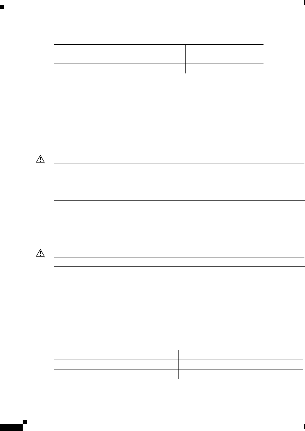
Figure 1-1 and Figure 1-2 show the fan side view of the Cisco Nexus 2300 Series chassis. Figure 1-3 and
Figure 1-4 show the port side view of the Cisco Nexus 2348TQ chassis, and Figure 1-5 and Figure 1-6
show the port side view of the Cisco Nexus 2348UPQ chassis.
1-3
Cisco Nexus 2000 Series Hardware Installation Guide
Chapter 1 Using a Fabric Extender with a Cisco Nexus 5000 Series or Cisco Nexus 6000 Series Switch
Cisco Nexus 2300 Series
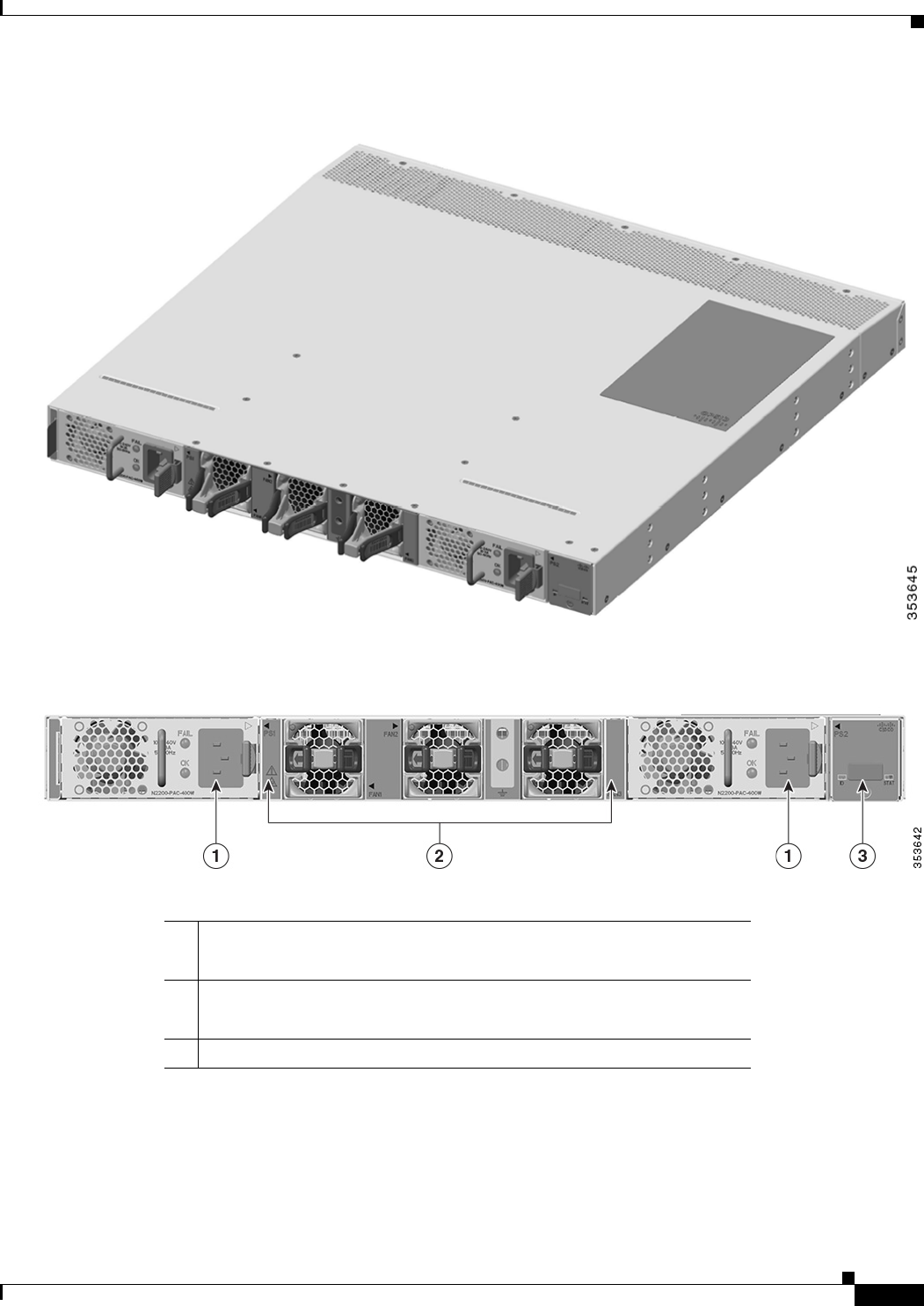
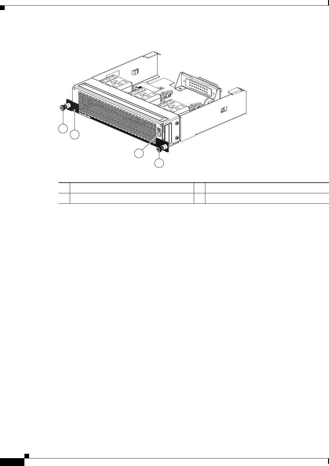
Figure 1-1 Fan Side View of the Cisco Nexus 2300 Series Chassis
Figure 1-2 Close up of Fan Side View of the Cisco Nexus 2300 Series Chassis
1Power supply
(two 1+1 redundant, hot-swappable power supplies)
2Fans
(three, hot-swappable independent fans with support for 2+1 redundancy
3Mgmt/Console port
1-4
Cisco Nexus 2000 Series Hardware Installation Guide
Chapter 1 Using a Fabric Extender with a Cisco Nexus 5000 Series or Cisco Nexus 6000 Series Switch
Cisco Nexus 2300 Series
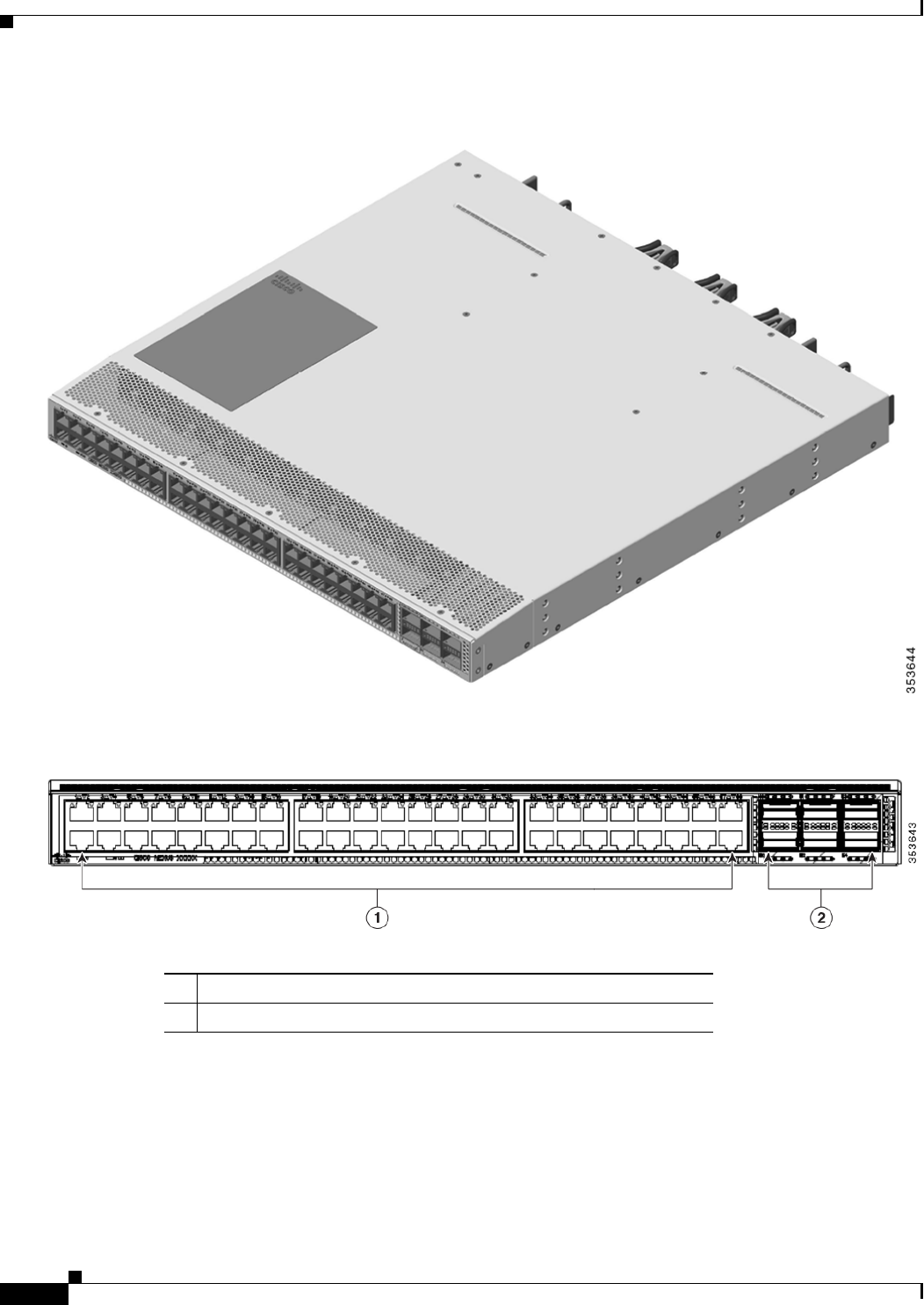
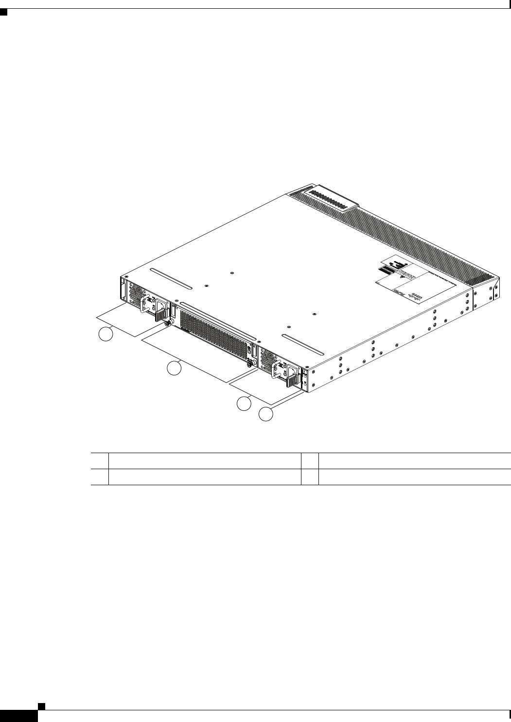
Figure 1-3 Port Side View of the Cisco Nexus 2348TQ Chassis
Figure 1-4 Close up of Port Side View of the Cisco Nexus 2348TQ Chassis
Figure 1-1 shows the fan side view of the Cisco Nexus 2348UPQ chassis, and Figure 1-3 shows the port
side view of the chassis.
148 Fixed 1/10GBASE-T SFP+ Ports
26 40G QSFP+ Ports
1-5
Cisco Nexus 2000 Series Hardware Installation Guide
Chapter 1 Using a Fabric Extender with a Cisco Nexus 5000 Series or Cisco Nexus 6000 Series Switch
Cisco Nexus 2300 Series
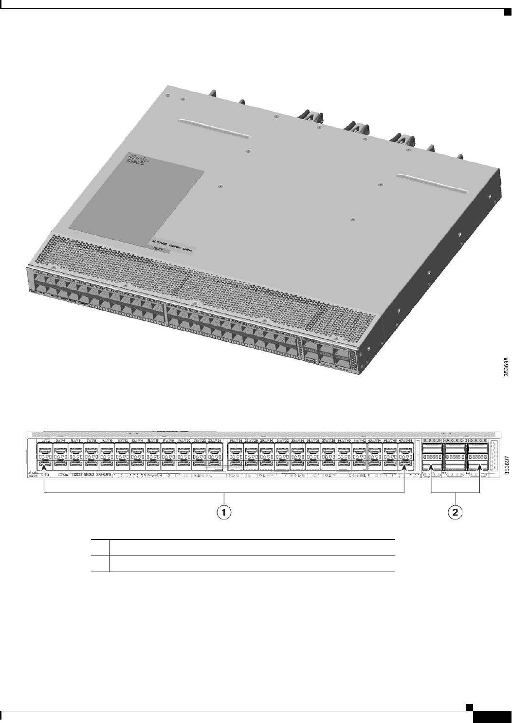
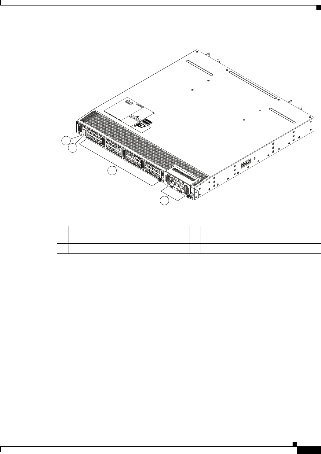
Figure 1-5 Port Side View of the Cisco Nexus 2348UPQ Chassis
Figure 1-6 Close up of Port Side View of the Cisco Nexus 2348UPQ Chassis
Ports
The Cisco Nexus 2300 Series platform provides host-facing downlink ports, network-facing uplink
ports, and service interface ports. The Cisco Nexus 2300 Series platform supports 48 1/10G host ports
as well as up to 6 40G uplink ports towards the parent switch.
148 Fixed 1/10G SFP+ Unified Capable Ports
26 40G QSFP+ Ports
1-6
Cisco Nexus 2000 Series Hardware Installation Guide
Chapter 1 Using a Fabric Extender with a Cisco Nexus 5000 Series or Cisco Nexus 6000 Series Switch
Cisco Nexus 2300 Series
On the Cisco Nexus 2348TQ, the host ports provide connectivity to 1/10GBASE-T Ethernet. Dedicated
uplink ports are color coded yellow (Network Interface Ports). Service Interface ports are color coded
white.
On the Cisco Nexus 2348UPQ the host unified ports provide connectivity to 1/10G Ethernet and FCoE.
Host ports with UP functionality are color coded orange (Host Interface Ports). Dedicated uplink ports
are color coded yellow (Network Interface Ports). Service Interface ports are color coded white.
Power Supplies
The Cisco Nexus 2300 Series platform has two 1+1 redundant power supplies. The chassis is fully
functional with one power supply, but you can install a second power supply for power redundancy. The
power supply is hot swappable during operations. Table 1-1 lists the power supplies that you can order
with the Cisco Nexus 2300 Series platform.
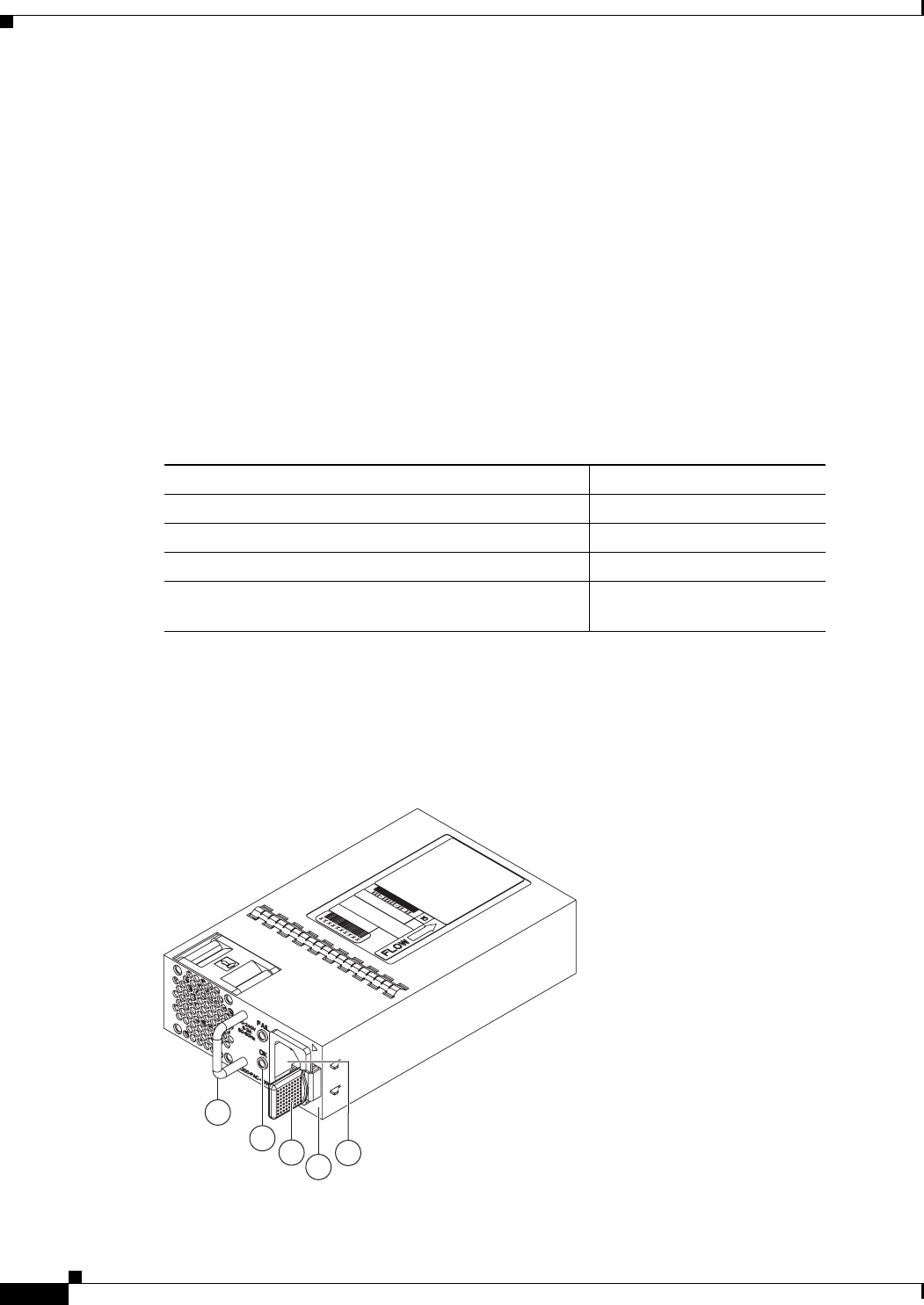
Figure 1-7 shows an AC power supply with port-side exhaust airflow. Figure 1-8 shows an AC power
supply with port-side intake airflow. Figure 1-9 shows a DC power supply with port-side exhaust airflow.
Figure 1-10 shows a DC power supply with port-side intake airflow.
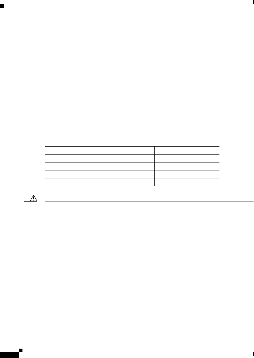
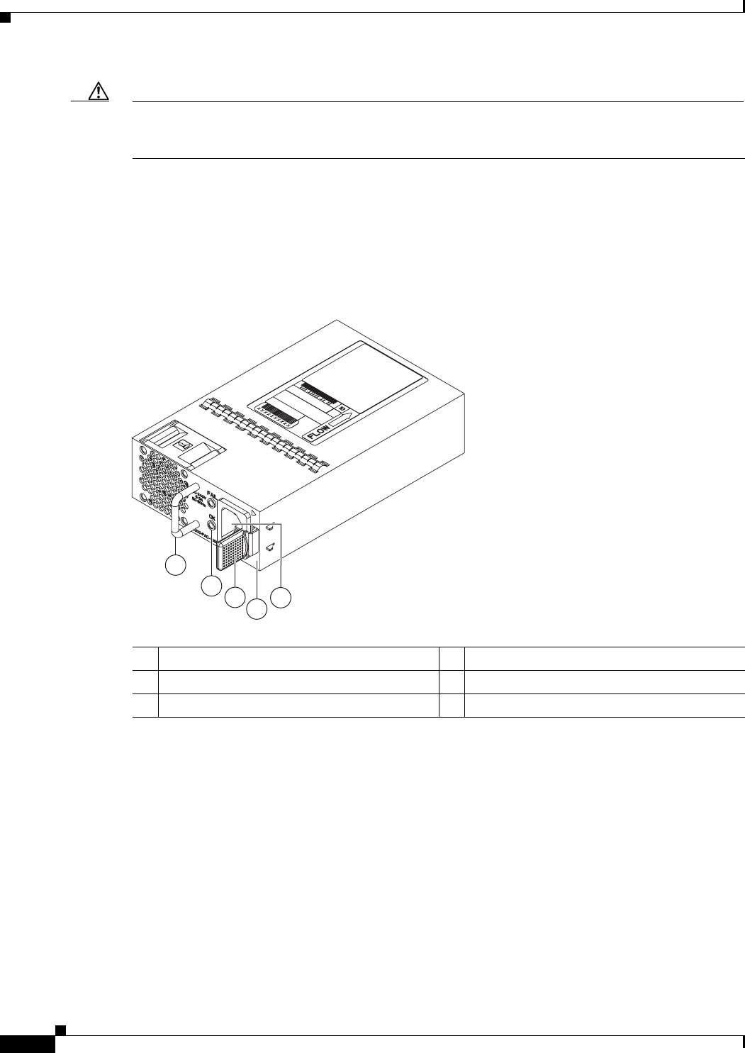
Figure 1-7 AC Power Supply with Port-Side Exhaust Airflow for the Cisco Nexus 2300 Platform
Chassis
Table 1-1 Power Supplies for the Cisco Nexus 2300 Platform Chassis
Power Supply Part Number
AC power supply with port side exhaust airflow (Blue) N2200-PAC-400W
AC power supply with port side intake airflow (Red) N2200-PAC-400W-B
DC power supply with port side exhaust airflow (Blue) N2200-PDC-400W
DC power supply with port side intake airflow (Red) N2200-PDC-350W-B (for
Cisco Nexus 2348UPQ only)
1
2
3
4
5
239843
1-7
Cisco Nexus 2000 Series Hardware Installation Guide
Chapter 1 Using a Fabric Extender with a Cisco Nexus 5000 Series or Cisco Nexus 6000 Series Switch
Cisco Nexus 2300 Series
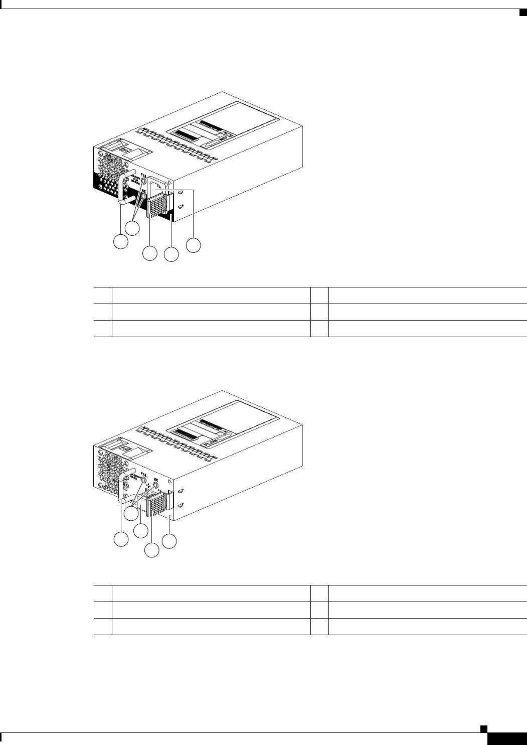
Figure 1-8 AC Power Supply with Port-Side Intake Airflow for the Cisco Nexus 2300 Platform
Chassis
Figure 1-9 DC Power Supply with Port-Side Exhaust Airflow for the Cisco Nexus 2300 Platform
Chassis
1Handle 4No black stripe (port side exhaust airflow)
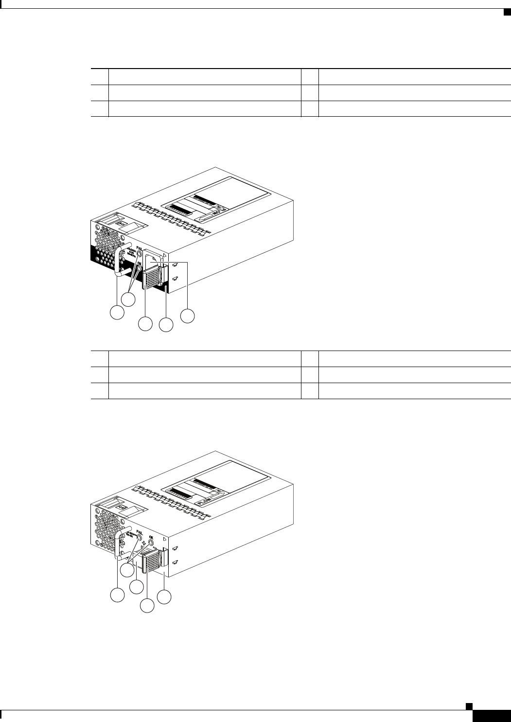
2FAIL (top) and OK (bottom) LEDs 5AC power receptacle
3Ejector latch
1Handle 4Black stripe (port side intake airflow)
2FAIL (top) and OK (bottom) LEDs 5AC power receptacle
3Ejector latch
1
34
5
239932
A220 P C-400
2
1
2
4
3
5
239933
1-8
Cisco Nexus 2000 Series Hardware Installation Guide
Chapter 1 Using a Fabric Extender with a Cisco Nexus 5000 Series or Cisco Nexus 6000 Series Switch
Cisco Nexus 2300 Series
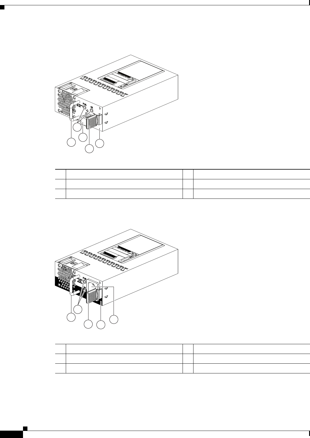
Figure 1-10 DC Power Supply with Port-Side Intake Airflow for the Cisco Nexus 2300 Platform
Chassis
You can order the Cisco Nexus 2300 Series platform with AC power supplies that have port-side exhaust
or port-side intake airflow for cooling or DC power supplies that offer port-side exhaust and port-side
intake airflow. The port-side intake airflow components have a black stripe on their front surface for easy
visual identification. The port-side exhaust airflow components do not have a black stripe.
Note Colored handles on each power supply clearly indicate the airflow direction.
Caution Be sure that all of the power supply and fan modules in the same chassis have the same airflow direction
and that the air intake for those modules is positioned on a cool aisle. If you install a module that uses a
different direction of airflow than the other modules in the same switch, the switch can overheat and shut
down. If you position a chassis with its modules taking cooling air from a warm aisle, the switch can
over heat and shut down.
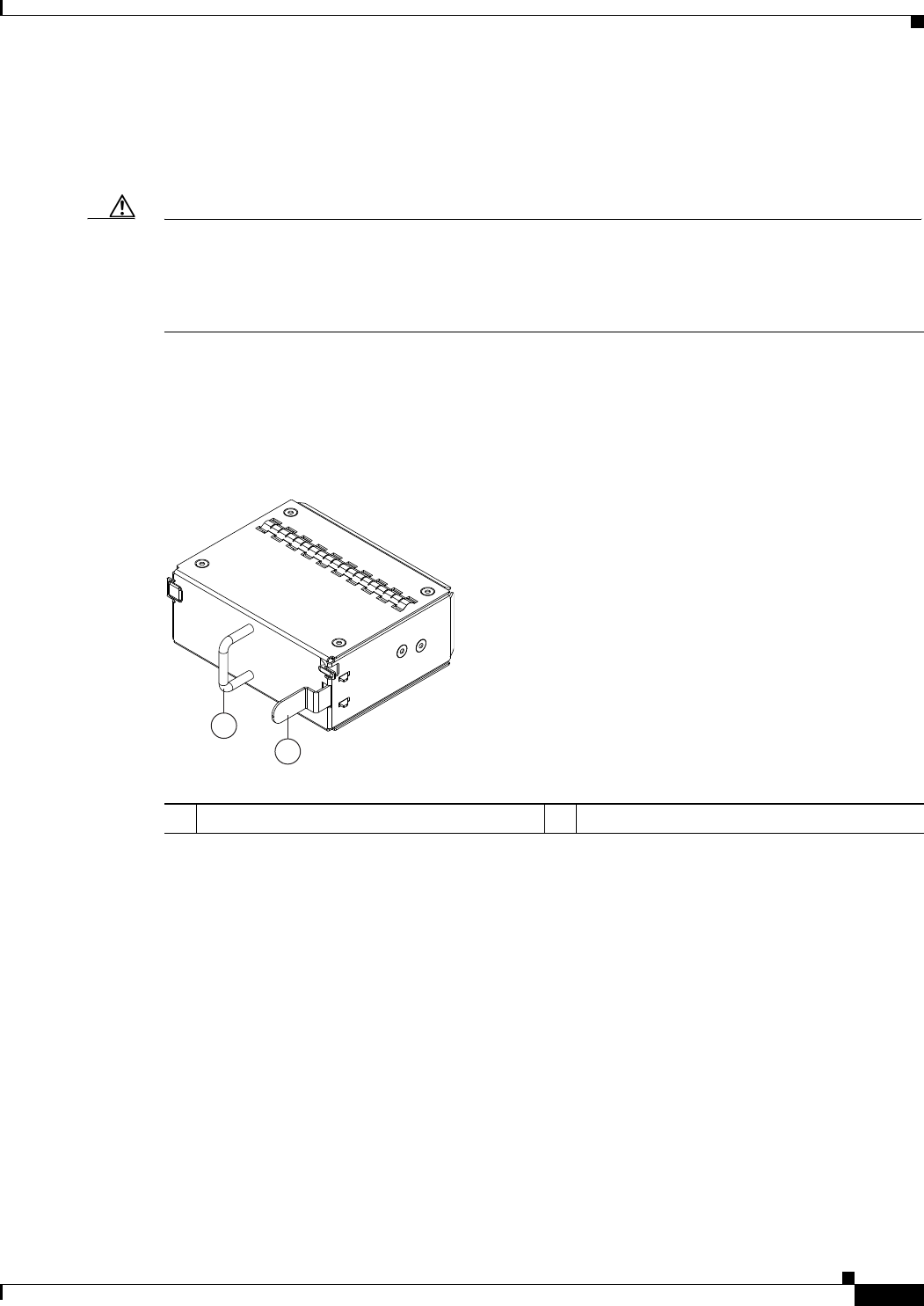
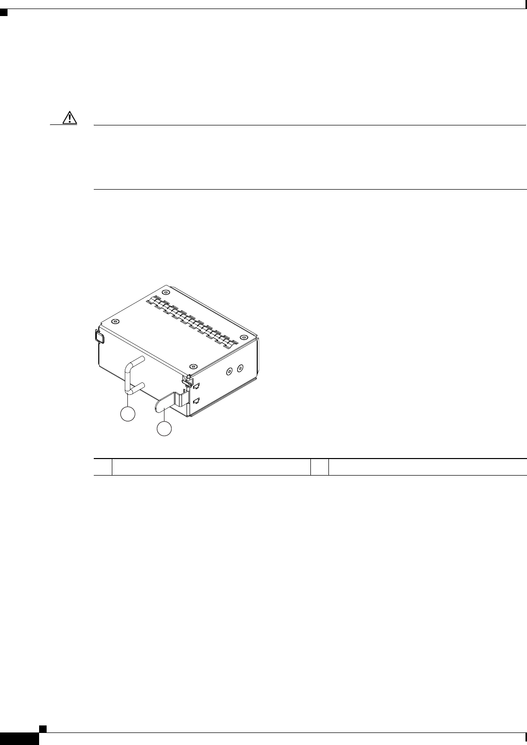
If one power supply is installed in the chassis, but the other power supply slot is empty, you should use
a blank filler panel (part number N2200-P-BLNK) to cover the empty slot. Figure 1-11 shows a blank
power supply filler panel.
1Handle 4Ejector latch
2FAIL (left) and OK (right) LEDs 5No black stripe (port side exhaust airflow)
3DC power receptacle
1Handle 4Black stripe (port side intake airflow)
2FAIL (top) and OK (bottom) LEDs 5AC power receptacle
3Ejector latch
1
34
5
239932
A220 P C-400
2
1-9
Cisco Nexus 2000 Series Hardware Installation Guide
Chapter 1 Using a Fabric Extender with a Cisco Nexus 5000 Series or Cisco Nexus 6000 Series Switch
Cisco Nexus 2300 Series
Figure 1-11 Blank Power Supply Filler Panel for the Cisco Nexus 2300 Platform Chassis
For power supply specifications, see the “Power Specifications” section on page B-1. To replace a power
supply, see the “Removing and Installing Power Supplies” section on page 4-16.
Fans
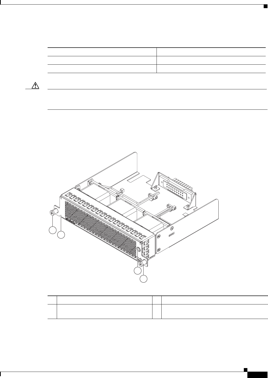
The Cisco Nexus 2300 Series platform has three, hot-swappable independent fans with support for 2+1
redundancy. Depending on the arrangement of hot and cold aisles in your data center, you can order
port-side exhaust airflow to position the fan side of the FEX chassis in a cold aisle or port-side intake
airflow to position the back of the FEX chassis in a cold aisle. Table 1-2 lists the part numbers for each
of the fans that you can use with the Cisco Nexus 2300 Series chassis.
Note Blue color coded tabs indicate port-side exhaust airflow. Red color coded tabs indicate port-side intake
airflow.
Caution Always make sure that all of the fan and power supply modules have the same direction of airflow and
the same color designation for that airflow direction. The switch does not support having more than one
direction of airflow with its modules.
To replace a fan, see the “Removing and Installing a Fan” section on page 4-19.
2
1
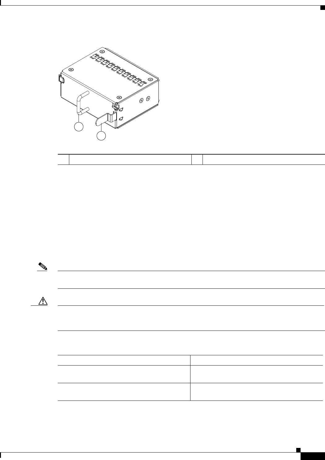
239290
1Handle 2Ejector latch
Table 1-2 Fans for the Cisco Nexus 2300 Series Chassis
Description Part Number
Port side exhaust airflow N2K-2348UPQ-FAN (2348UPQ)
N2K-2348TQ-FAN (2348TQ)
Port side intake airflow N2K-2348UPQ-FAN-B (2348UPQ)
N2K-2348TQ-FAN-B (2348TQ)

1-10
Cisco Nexus 2000 Series Hardware Installation Guide
Chapter 1 Using a Fabric Extender with a Cisco Nexus 5000 Series or Cisco Nexus 6000 Series Switch
Cisco Nexus 2248TP-E
Supported Transceivers and Cables
The Cisco Nexus 2300 Series platform supports a wide variety of 1, 10, and 40 Gigabit Ethernet
connectivity options.
Caution Currently, passive copper cables are not supported on the NIF/SIF ports. Also, 100M FX optics are not
supported.
For the most current list of supported transceivers and optics, refer to the latest Cisco Nexus 2000 Series
Fabric Extenders Release Notes at every release.
Cisco Nexus 2248TP-E
The Cisco Nexus 2248TP-E is a stackable 1 RU 17.2-inch (45 cm) deep FEX that supports 48 1000-TX
host-facing (downlink) ports and 4 10-Gigabit SFP+ network-facing (uplink) ports. You can order it with
port side exhaust or port side intake air cooling, and with AC or DC power supplies.
You can use this FEX with the Cisco Nexus 5000 Series switch. The Cisco Nexus 2248TP-E is managed
and configured by the upstream switch. The FEX software ships with the Cisco Nexus 5000 Series
switch software. The FEX downloads the software image from the switch the same way that a module
would download it from the supervisor in a modular chassis.
This section includes the following topics:
•Chassis, page 1-10
•Ports, page 1-12
•Power Supplies, page 1-12
•Fan Trays, page 1-15
•Supported Transceivers and Cables, page 1-17
Chassis
The Cisco Nexus 2248TP-E FEX chassis has a height of 1.72 inches (4.37 cm), a width of 17.3 inches
(43.94 cm), and a depth of 17.7 inches (44.96 cm). It weighs 17.7 pounds (8.0 kg). Its one-rack-unit (1
RU) form factor takes up relatively little space, making it easy to incorporate into rack designs. The FEX
is mounted in a standard 19-inch (48.26 cm) rack. All switch ports at the rear of the unit are in close
proximity to server ports, and all user-serviceable components are accessible from the fan side.
You can order it with port-side exhaust or port-side intake air cooling, and with AC or DC power
supplies. If you are going to install the chassis with its fan side facing the cold aisle, you must order the
chassis with port-side exhaust air flow. If you are going to install the chassis with its back end facing the
cold aisle, you must order the chassis with port-side intake airflow.
Caution Always make sure that all of the fan tray and power supply modules have the same direction of airflow
and the same color designation for that airflow direction. The switch does not support having more than
one direction of airflow with its modules.
1-11
Cisco Nexus 2000 Series Hardware Installation Guide
Chapter 1 Using a Fabric Extender with a Cisco Nexus 5000 Series or Cisco Nexus 6000 Series Switch
Cisco Nexus 2248TP-E
Figure 1-12 shows the location of the components found on the fan side of the chassis, and Figure 1-13
shows the location of components found on the rear of the chassis. For information on what the chassis
and component LEDs indicate, see Table E-1 on page E-2.
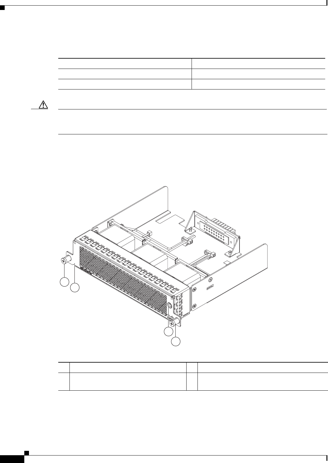
Figure 1-12 Fan side view of the Cisco Nexus 2248TP-E Chassis
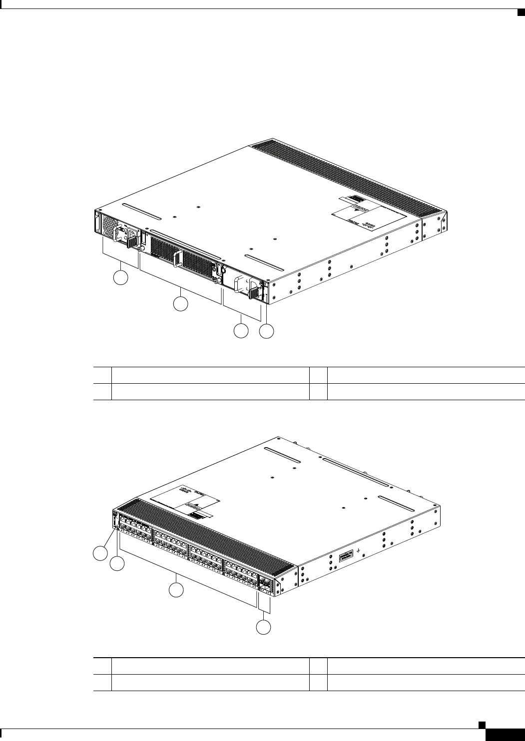
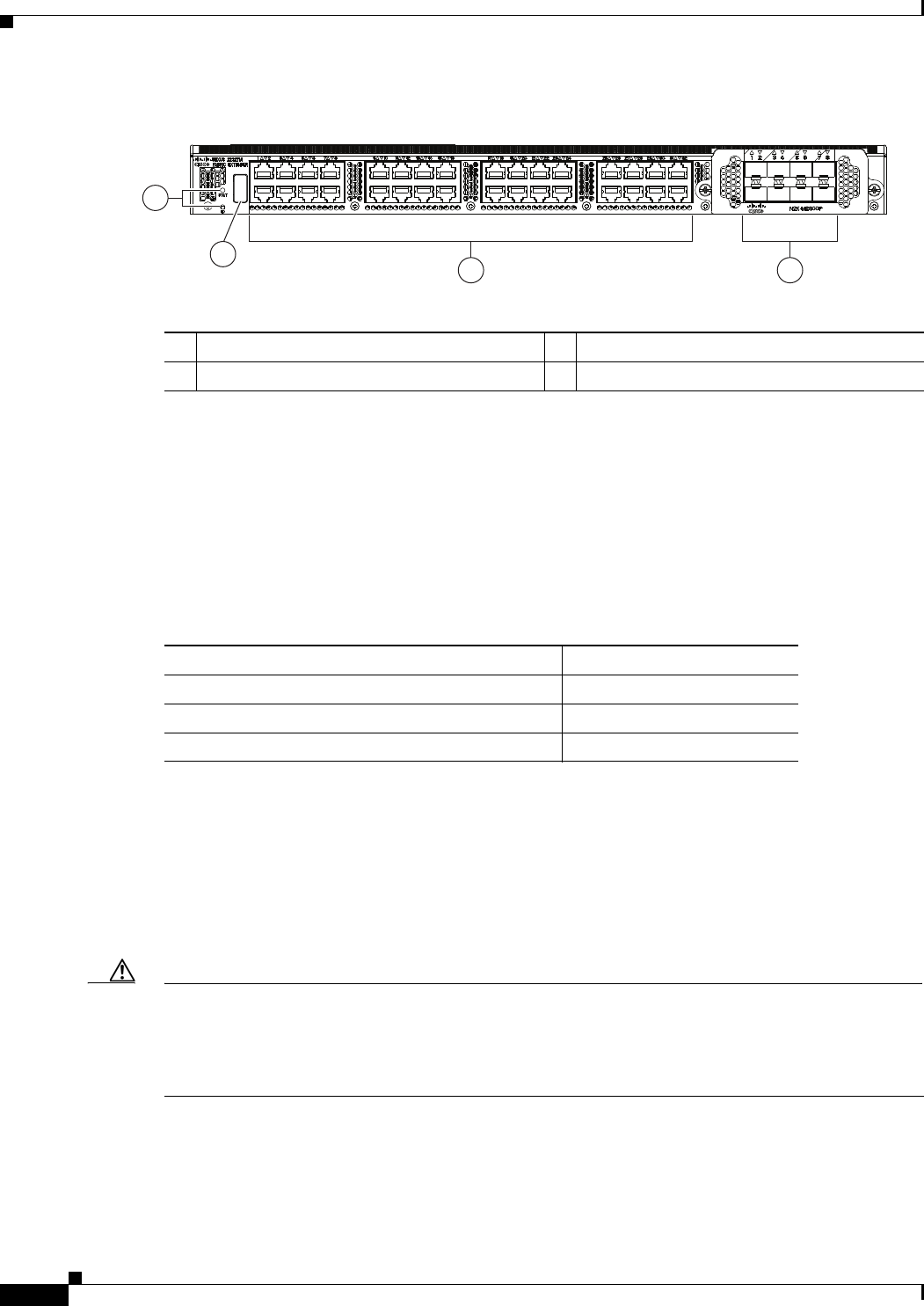
Figure 1-13 Rear View of the Cisco Nexus 2248TP-E Chassis
2
1
34
239288
1Power supply 3Power supply (blank shown)
2Fan tray 4Status (top) and ID (bottom) LEDs
3
2
4
1
239287
1Status (top) and ID (bottom) LEDs 3100/1000 downlink ports (48)
2HDMI port 4SFP+ uplink ports (four)
1-12
Cisco Nexus 2000 Series Hardware Installation Guide
Chapter 1 Using a Fabric Extender with a Cisco Nexus 5000 Series or Cisco Nexus 6000 Series Switch
Cisco Nexus 2248TP-E
Ports
The Cisco Nexus 2248TP-E FEX supports a total of 48 100/1000BASE-T ports and four 10-Gigabit
Ethernet uplinks (SFP+). The Cisco Nexus 2300 series provides three types of ports: ports for end-host
attachment (host interfaces), uplink ports (fabric interfaces) and flexible ports (to be configured as either
host or fabric interfaces). Fabric interfaces are for connectivity to the upstream parent Cisco Nexus
switch and are indicated by yellow color. Flexible interfaces can be used for connectivity to the upstream
parent or towards the host, and are indicated by white color.
Power Supplies
The Cisco Nexus 2248TP-E FEX chassis has two bays for fan side AC or DC power supplies. This
chassis is fully functional with one power supply, but you can install a second power supply for power
redundancy. The power supply is hot swappable during operations.
Table 1-3 lists the power supplies that you can order with the Cisco Nexus 2248TP-E FEX.
Caution Always make sure that all of the fan tray and power supply modules have the same direction of airflow
and the same color designation for that airflow direction. The switch does not support having more than
one direction of airflow with its modules.
Figure 1-14 shows an AC power supply with port-side exhaust airflow. Figure 1-15 shows an AC power
supply with port-side intake airflow. Figure 1-16 shows a DC power supply with port-side exhaust
airflow. Figure 1-17 shows a DC power supply with port-side intake airflow.
Table 1-3 Power Supplies for the Cisco Nexus 2200 and Cisco Nexus 2300 Platform Chassis
Power Supply Part Number
AC power supply with port-side exhaust airflow N2200-PAC-400W
AC power supply with port-side intake airflow N2200-PAC-400W-B
DC power supply with port-side exhaust airflow N2200-PDC-400W
DC power supply with port-side intake airflow N2200-PDC-350W-B
1-13
Cisco Nexus 2000 Series Hardware Installation Guide
Chapter 1 Using a Fabric Extender with a Cisco Nexus 5000 Series or Cisco Nexus 6000 Series Switch
Cisco Nexus 2248TP-E
Figure 1-14 AC Power Supply with Port-Side exhaust Airflow for the Cisco Nexus 2200 and Cisco
Nexus 2300 Platform Chassis
Figure 1-15 AC Power Supply with Port-Side Intake Airflow for the Cisco Nexus 2200 and Cisco
Nexus 2300 Platform Chassis
1
2
3
4
5
239843
1Handle 4No black stripe (port-side exhaust airflow)
2FAIL (top) and OK (bottom) LEDs 5AC power receptacle
3Ejector latch
1
34
5
239932
A220 P C-400
2
1Handle 4Black stripe (port side intake airflow)
2FAIL (top) and OK (bottom) LEDs 5AC power receptacle
3Ejector latch
1-14
Cisco Nexus 2000 Series Hardware Installation Guide
Chapter 1 Using a Fabric Extender with a Cisco Nexus 5000 Series or Cisco Nexus 6000 Series Switch
Cisco Nexus 2248TP-E
Figure 1-16 DC Power Supply with Port-Side Exhaust Airflow for the Cisco Nexus 2200 and Cisco
Nexus 2300 Platform Chassis
Figure 1-17 DC Power Supply with Port-Side Intake Airflow for the Cisco Nexus 2200 and Cisco
Nexus 2300 Platform Chassis
1
2
4
3
5
239933
1Handle 4Ejector latch
2FAIL (left) and OK (right) LEDs 5No black stripe (port-side exhaust airflow)
3DC power receptacle
1
34
5
239932
A220 P C-400
2
1Handle 4Black stripe (port-side intake airflow)
2FAIL (top) and OK (bottom) LEDs 5AC power receptacle
3Ejector latch
1-15
Cisco Nexus 2000 Series Hardware Installation Guide
Chapter 1 Using a Fabric Extender with a Cisco Nexus 5000 Series or Cisco Nexus 6000 Series Switch
Cisco Nexus 2248TP-E
You can order the Cisco Nexus 2248TP-E FEX with AC power supplies that have port side exhaust or
port side intake airflow for cooling or DC power supplies that offer port side exhaust airflow. The port
side intake airflow components have a black stripe on their fan side surface for easy visual identification.
The port side exhaust airflow components do not have a black stripe.
Caution Be sure that all of the power supply and fan tray modules in the same chassis have the same airflow
direction and that the air intake for those modules is positioned on a cool aisle. If you install a module
that uses a different direction of airflow from the other modules in your system, you will see an error
message. If you position a chassis with its modules taking cooling air from a warm aisle, the switch can
over heat and shut down.
If one power supply is installed in the chassis, but the other power supply slot is empty, you should use
a blank filler panel (part number N2200-P-BLNK) to cover the empty slot. Figure 1-18 shows a blank
power supply filler panel.
Figure 1-18 Blank Power Supply Filler Panel for the Cisco Nexus 2200 and Cisco Nexus 2300
Platform Chassis
For power supply specifications, see the “Power Specifications” section on page B-1. To replace a power
supply, see the “Removing and Installing Power Supplies” section on page 4-16. For LED descriptions,
see Table E-1 on page E-2.
Fan Trays
The Cisco Nexus 2248TP-E FEX has one fan tray that is hot swappable during operations. Depending
on the arrangement of hot and cold aisles in your data center, you can order port-side exhaust airflow to
position the fan side of the FEX chassis in a cold aisle or port-side intake airflow to position the back of
the FEX chassis in a cold aisle. Table 1-4 lists the part numbers for each of the fan trays that you can use
with the Cisco Nexus 2248TP-E chassis.
2
1
239290
1Handle 2Ejector latch
1-16
Cisco Nexus 2000 Series Hardware Installation Guide
Chapter 1 Using a Fabric Extender with a Cisco Nexus 5000 Series or Cisco Nexus 6000 Series Switch
Cisco Nexus 2248TP-E
Caution Always make sure that all of the fan tray and power supply modules have the same direction of airflow
and the same color designation for that airflow direction. The switch does not support having more than
one direction of airflow with its modules.
Figure 1-19 shows a port-side exhaust airflow fan tray, and Figure 1-20 shows a port-side intake airflow
fan tray.
Figure 1-19 Port-Side Exhaust Airflow Fan Tray Components for the Cisco Nexus 2248TP-E and
2224TP FEXs
Table 1-4 Fan Trays for the Cisco Nexus 2248TP-E FEXs
Description Part Number
port-side exhaust airflow N2K-C2248TP-FAN
port-side intake airflow N2K-C2248TP-FAN-B
3
2
1
1
239291
1Captive screws (2) 3Status LED
2 No black stripe indicates port-side exhaust
airflow
1-17
Cisco Nexus 2000 Series Hardware Installation Guide
Chapter 1 Using a Fabric Extender with a Cisco Nexus 5000 Series or Cisco Nexus 6000 Series Switch
Cisco Nexus 2248TP
Figure 1-20 Port-Side Intake Airflow Fan Tray for the Cisco Nexus 2248TP-E FEX
To replace a fan tray, see the “Removing and Installing the Fan Tray” section on page 4-21. For LED
descriptions, see Table E-1 on page E-2.
Supported Transceivers and Cables
The Cisco Nexus 2248TP-E FEX supports SFP+ Ethernet transceivers. The enhanced
Small-Form-Factor Pluggable (SFP+) 10-Gigabit Ethernet transceiver is a bidirectional device with a
transmitter and receiver. It has a 20-pin connector on the electrical interface and duplex LC connector
on the optical interface. Currently, the Cisco Nexus 2248TP-E FEX supports the short-range SFP and
long-range SFP transceiver. Copper interface cables are available for use with the 10-Gigabit Ethernet
SFP+ transceiver. For details see, the Cisco Nexus 2000 Series Fabric Extenders Release Notes.
Cisco Nexus 2248TP
The Cisco Nexus 2248TP is a stackable 1 RU 17.2-inch (45 cm) deep FEX that supports 48 1000-TX
host-facing (downlink) ports and 4 10-Gigabit SFP+ network-facing (uplink) ports. You can order it with
port side exhaust or port side intake air cooling, and with AC or DC power supplies.
You can use this FEX with the Cisco Nexus 5000 Series switch. The Cisco Nexus 2248TP is managed
and configured by the upstream switch. The FEX software ships with the Cisco Nexus 5000 Series
switch software. The FEX downloads the software image from the switch the same way that a module
would download it from the supervisor in a modular chassis.
This section includes the following topics:
•Chassis, page 1-18
•Ports, page 1-19
2
1
3
239934
1
1Captive screws (2) 3Status LED
2 Black stripe indicates port-side intake airflow
1-18
Cisco Nexus 2000 Series Hardware Installation Guide
Chapter 1 Using a Fabric Extender with a Cisco Nexus 5000 Series or Cisco Nexus 6000 Series Switch
Cisco Nexus 2248TP
•Power Supplies, page 1-19
•Fan Tray, page 1-22
•Supported Transceivers and Cables, page 1-24
Chassis
The Cisco Nexus 2248TP FEX chassis has a height of 1.72 inches (4.37 cm), a width of 17.3 inches
(43.94 cm), and a depth of 17.7 inches (44.96 cm). It weighs 17.7 pounds (8.0 kg). Its one-rack-unit (1
RU) form factor takes up relatively little space, making it easy to incorporate into rack designs. The FEX
is mounted in a standard 19-inch (48.26 cm) rack. All switch ports at the rear of the unit are in close
proximity to server ports, and all user-serviceable components are accessible from the fan side.
You can order it with port-side exhaust or port-side intake air cooling (do not mix air directions for a
chassis), and with AC or DC power supplies. If you are going to install the chassis with its fan side facing
the cold aisle, you must order the chassis with port-side exhaust airflow. If you are going to install the
chassis with its back end facing the cold aisle, you must order the chassis with port-side intake airflow.
Figure 1-21 shows the location of the components found on the fan side of the chassis, and Figure 1-22
shows the location of components found on the rear of the chassis. For information on what the chassis
and component LEDs indicate, see Table E-1 on page E-2.
Figure 1-21 Fan side view of the Cisco Nexus 2248TP Chassis
2
1
34
239288
1Power supply 3Power supply (blank shown)
2Fan tray 4Status (top) and ID (bottom) LEDs
1-19
Cisco Nexus 2000 Series Hardware Installation Guide
Chapter 1 Using a Fabric Extender with a Cisco Nexus 5000 Series or Cisco Nexus 6000 Series Switch
Cisco Nexus 2248TP
Figure 1-22 Rear View of the Cisco Nexus 2248TP Chassis
Ports
The Cisco Nexus 2248TP FEX supports a total of 48 100/1000BASE-T ports and four, 10-Gigabit
Ethernet uplinks (SFP+). It provides two types of ports: host-facing downlink ports and network-facing
uplink ports. Uplink ports are differentiated with yellow for connectivity to the upstream parent Cisco
Nexus 5000 Series switch.
Power Supplies
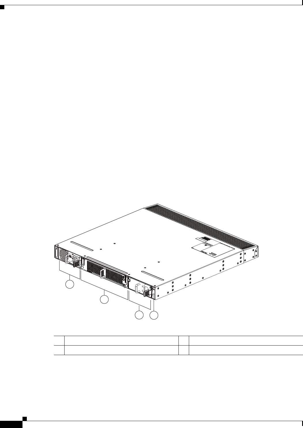
The Cisco Nexus 2248TP FEX chassis has two bays for fan side AC or DC power supplies. This chassis
is fully functional with one power supply, but you can install a second power supply for power
redundancy. The power supply is hot swappable during operations.
Table 1-5 lists the power supplies that you can order with the Cisco Nexus 2248TP FEX.
3
2
4
1
239287
1Status (top) and ID (bottom) LEDs 3100/1000 downlink ports (48)
2HDMI port 4SFP+ uplink ports (four)
Table 1-5 Power Supplies for the Cisco Nexus 2200 and Cisco Nexus 2300 Platform Chassis
Power Supply Part Number
AC power supply with port-side exhaust airflow N2200-PAC-400W
AC power supply with port-side intake airflow N2200-PAC-400W-B
DC power supply with port-side exhaust airflow N2200-PDC-400W
DC power supply with port-side intake airflow N2200-PDC-350W-B
1-20
Cisco Nexus 2000 Series Hardware Installation Guide
Chapter 1 Using a Fabric Extender with a Cisco Nexus 5000 Series or Cisco Nexus 6000 Series Switch
Cisco Nexus 2248TP
Caution Always make sure that all of the fan tray and power supply modules have the same direction of airflow
and the same color designation for that airflow direction. The switch does not support having more than
one direction of airflow with its modules.
Figure 1-23 shows an AC power supply with port-side exhaust airflow. Figure 1-24 shows an AC power
supply with port-side intake airflow. Figure 1-25 shows a DC power supply with port-side exhaust
airflow.
Figure 1-23 AC Power Supply with Port-Side Exhaust Airflow for the Cisco Nexus 2200 and Cisco
Nexus 2300 Platform Chassis
1
2
3
4
5
239843
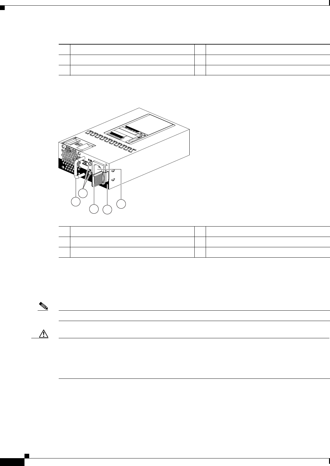
1Handle 4No black stripe (port-side exhaust airflow)
2OK (top) and FAULT (bottom) LEDs 5AC power receptacle
3Ejector latch
1-21
Cisco Nexus 2000 Series Hardware Installation Guide
Chapter 1 Using a Fabric Extender with a Cisco Nexus 5000 Series or Cisco Nexus 6000 Series Switch
Cisco Nexus 2248TP
Figure 1-24 AC Power Supply with Port-Side Intake Airflow for the Cisco Nexus 2200 and Cisco
Nexus 2300 Platform Chassis
Figure 1-25 DC Power Supply with Port-Side Exhaust Airflow for the Cisco Nexus 2200 and Cisco
Nexus 2300 Platform Chassis
1
34
5
239932
A220 P C-400
2
1Handle 4Black stripe (port-side intake airflow)
2FAULT (top) and OK (bottom) LEDs 5AC power receptacle
3Ejector latch
1
2
4
3
5
239933
1Handle 4Ejector latch
2FAULT (top) and OK (bottom) LEDs 5No black stripe (port-side exhaust airflow)
3DC power receptacle
1-22
Cisco Nexus 2000 Series Hardware Installation Guide
Chapter 1 Using a Fabric Extender with a Cisco Nexus 5000 Series or Cisco Nexus 6000 Series Switch
Cisco Nexus 2248TP
You can order the Cisco Nexus 2248TP FEX with AC power supplies that have port-side exhaust or
port-side intake airflow for cooling or DC power supplies that offer port-side exhaust airflow. The
port-side intake airflow components have a black stripe on their fan side surface for easy visual
identification. The port-side exhaust airflow components do not have a black stripe.
Caution Be sure that all of the power supply and fan tray modules in the same chassis have the same airflow
direction and that the air intake for those modules is positioned on a cool aisle. If you install a module
that uses a different direction of airflow from the other modules in your system, you will see an error
message. If you position a chassis with its modules taking cooling air from a warm aisle, the switch can
over heat and shut down.
If one power supply is installed in the chassis, but the other power supply slot is empty, you should use
a blank filler panel (part number N2200-P-BLNK) to cover the empty slot. Figure 1-26 shows a blank
power supply filler panel.
Figure 1-26 Blank Power Supply Filler Panel for the Cisco Nexus 2200 and Cisco Nexus 2300
Platform Chassis
For power supply specifications, see the “Power Specifications” section on page B-1. To replace a power
supply, see the “Removing and Installing Power Supplies” section on page 4-16. For LED descriptions,
see Table E-1 on page E-2.
Fan Tray
The Cisco Nexus 2248TP (and 2224TP) FEX has one fan tray that is hot swappable during operations.
Depending on the arrangement of hot and cold aisles in your data center, you can order port-side exhaust
airflow to position the fan side of the FEX chassis in a cold aisle or port-side intake airflow to position
the back of the FEX chassis in a cold aisle. Table 1-6 lists the part numbers for each of the fan trays that
you can use with the Cisco Nexus 2248TP and 2224TP chassis.
2
1
239290
1Handle 2Ejector latch
1-23
Cisco Nexus 2000 Series Hardware Installation Guide
Chapter 1 Using a Fabric Extender with a Cisco Nexus 5000 Series or Cisco Nexus 6000 Series Switch
Cisco Nexus 2248TP
Caution Always make sure that all of the fan tray and power supply modules have the same direction of airflow
and the same color designation for that airflow direction. The switch does not support having more than
one direction of airflow with its modules.
Figure 1-27 shows a port-side exhaust airflow fan tray, and Figure 1-28 shows a port side intake airflow
fan tray.
Figure 1-27 Port-Side Exhaust Airflow Fan Tray Components for the Cisco Nexus 2248TP and
2224TP FEXs
Table 1-6 Fan Trays for the Cisco Nexus 2248TP and 2224TP FEXs
Description Part Number
Port-side exhaust airflow N2K-C2248-FAN
Port-side intake airflow N2K-C2248-FAN-B
3
2
1
1
239291
1Captive screws (2) 3Status LED
2 No black stripe indicates port-side exhaust
airflow
1-24
Cisco Nexus 2000 Series Hardware Installation Guide
Chapter 1 Using a Fabric Extender with a Cisco Nexus 5000 Series or Cisco Nexus 6000 Series Switch
Cisco Nexus 2248PQ
Figure 1-28 Port-Side Intake Airflow Fan Tray for the Cisco Nexus 2248TP and 2224TP FEXs
To replace a fan tray, see the “Removing and Installing the Fan Tray” section on page 4-21. For LED
descriptions, see Table E-1 on page E-2.
Supported Transceivers and Cables
The Cisco Nexus 2248TP FEX supports SFP+ Ethernet transceivers. The enhanced Small-Form-Factor
Pluggable (SFP+) 10-Gigabit Ethernet transceiver is a bidirectional device with a transmitter and
receiver. It has a 20-pin connector on the electrical interface and duplex LC connector on the optical
interface. Currently, the Cisco Nexus 2000 Series FEX supports the short-range SFP and long-range SFP
transceiver. Copper interface cables are available for use with the 10-Gigabit Ethernet SFP+ transceiver.
For an updated list of supported transceivers and optics, please see the Cisco Nexus 2000 Series Fabric
Extenders Release Notes.
Cisco Nexus 2248PQ
The Cisco Nexus 2248PQ is a stackable 1 RU 17.2 inch (45 cm) deep FEX that supports high-density
10-Gigabit Ethernet environments and has 48 1/10-Gigabit SFP+ host interfaces and 4 QSFP+ (16
10-Gigabit) on network interfaces. QSFP+ connectivity simplifies cabling while lowering power and
solution costs. You can order it with port side exhaust or port side intake air cooling, which makes this
FEX compatible with hot-aisle, cold aisle data center designs.
You can use this FEX with the Cisco Nexus 5500 Series switch and the Cisco Nexus 6004 parent switch
(The supported software is Cisco Nexus OS Release 6.0(2)N1(1)). The Cisco Nexus 2248PQ is managed
and configured by the upstream switch. The FEX software ships with the Cisco Nexus 5500 Series
switch software. The FEX downloads the software image from the switch the same way that a module
would download it from the supervisor in a modular chassis.
2
1
3
239934
1
1Captive screws (2) 3Status LED
2 Black stripe indicates port-side intake airflow

1-25
Cisco Nexus 2000 Series Hardware Installation Guide
Chapter 1 Using a Fabric Extender with a Cisco Nexus 5000 Series or Cisco Nexus 6000 Series Switch
Cisco Nexus 2248PQ
This section includes the following topics:
•Chassis, page 1-25
•Ports, page 1-25
•Power Supplies, page 1-25
•Fan Trays, page 1-26
•Supported SFP+ Transceivers, page 1-27
Chassis
The Cisco Nexus 2248PQ FEX chassis has a height of 1.72 inches (4.37 cm), a width of 17.3 inches
(43.94 cm), and a depth of 17.7 inches (44.96 cm). It weighs 17.5 pounds (8.0 kg). Its one-rack-unit (1
RU) form factor takes up relatively little space, making it easy to incorporate into rack designs. The FEX
is mounted in a standard 19-inch (48.26 cm) rack. All of the switch ports at the rear of the chassis are in
close proximity to server ports, and all user-serviceable components are accessible from the fan side.
You can order port-side exhaust airflow or port-side intake airflow for cooling. If you are going to install
the chassis with its fan side facing the cold aisle, you must order the chassis with port-side exhaust air
flow. If you are going to install the chassis with its back end facing the cold aisle, you must order the
chassis with port-side intake airflow.
Ports
The Cisco Nexus 2248PQ FEX supports a total of 48 1/10-Gigabit Ethernet/Fibre Channel over Ethernet
(FCoE) ports (SFP+) and 4 QSFP+ (16 10-Gigabit) fabric ports. The Cisco Nexus 2248PQ provides two
types of ports: ports for end-host attachments and uplink ports. Uplink ports are differentiated with
yellow for connectivity to the upstream parent Cisco Nexus 5000 Series switch.
The Cisco Nexus 2248PQ 10GE Fabric Extender supports FCoE and Data Center Bridging (DCB) which
increases the reliability, efficiency, and scalability of Ethernet networks by allowing the switches to
support multiple traffic classes over a lossless Ethernet fabric, enabling consolidation of LAN, SAN, and
cluster environments.
Power Supplies
The Cisco Nexus 2248PQ FEX chassis has two bays for fan side AC or DC power supplies. This chassis
is fully functional with one power supply, but you can install a second power supply for power
redundancy. The power supply is hot swappable during operations.
Table 1-7 lists the power supplies that you can order with the Cisco Nexus 2248PQ FEX.
Table 1-7 Power Supplies for the Cisco Nexus 2200 and Cisco Nexus 2300 Platform Chassis
Power Supply Part Number
AC power supply with port-side exhaust airflow N2200-PAC-400W
AC power supply with port-side intake airflow N2200-PAC-400W-B
1-26
Cisco Nexus 2000 Series Hardware Installation Guide
Chapter 1 Using a Fabric Extender with a Cisco Nexus 5000 Series or Cisco Nexus 6000 Series Switch
Cisco Nexus 2248PQ
Figure 1-23 on page 1-20 shows an AC power supply with port-side exhaust airflow. Figure 1-24 on
page 1-21 shows an AC power supply with port-side intake airflow. Figure 1-25 on page 1-21 shows a
DC power supply with port-side exhaust airflow.
You can order the Cisco Nexus 2248PQ FEX with AC power supplies that have port-side exhaust or
port-side intake airflow for cooling or DC power supplies that have port-side exhaust airflow. The
port-side intake airflow components have a black stripe on their fan side surface for easy visual
identification. The port-side exhaust airflow components do not have a black stripe.
Table 1-5 on page 1-19 lists the power supplies that you can order with the Cisco Nexus 2200 and Cisco
Nexus 2300 Platform FEXs.
Caution Be sure that all of the power supply and fan tray modules in the same chassis have the same airflow
direction and that the air intake for those modules is positioned on a cool aisle. If you install a module
that uses a different direction of airflow from the other modules in your system, you will see an error
message. If you position a chassis with its modules taking cooling air from a warm aisle, the switch can
over heat and shut down.
If one power supply is installed in the chassis, but the other power supply slot is empty, you should use
a blank filler panel (N2200-P-BLNK) to cover the empty slot. Figure 1-26 on page 1-22 shows a blank
power supply filler panel.
For power supply specifications, see “Power Specifications”. To replace a power supply, see the
“Removing and Installing Power Supplies” section on page 4-16.
Caution Hot swapping of different direction fans and power supplies is not supported.
Fan Trays
The Cisco Nexus 2248PQ FEX has one fan tray that is hot swappable during operations. Depending on
whether there is a cold aisle in the fan side or port side of the chassis, you can order port side exhaust
airflow or port side intake airflow for the fan tray and the power supplies in the same chassis. Table 1-8
lists the part numbers for each of the fan trays that you can use with this chassis.
DC power supply with port-side exhaust airflow N2200-PDC-400W
DC power supply with port-side intake airflow N2200-PDC-350W-B
Table 1-7 Power Supplies for the Cisco Nexus 2200 and Cisco Nexus 2300 Platform Chassis
Power Supply Part Number
Table 1-8 Fan Trays for the Cisco Nexus 2248PQ FEX
Description Part Number
Port-side exhaust airflow (blue color coded fans) N2K-C2248PQ-FAN
Port-side intake airflow (red color coded fans) N2K-C2248PQ-FAN-B

1-27
Cisco Nexus 2000 Series Hardware Installation Guide
Chapter 1 Using a Fabric Extender with a Cisco Nexus 5000 Series or Cisco Nexus 6000 Series Switch
Cisco Nexus 2232TM-10GE, Cisco Nexus N2K-C2232TM-E-10GE
Caution Always make sure that all of the fan tray and power supply modules have the same direction of airflow
and the same color designation for that airflow direction. The switch does not support having more than
one direction of airflow with its modules.
To replace a fan tray, see the “Removing and Installing the Fan Tray” section on page 4-21. For LED
descriptions, see “Chassis and Module LEDs for the Cisco Nexus Fabric Extenders”.
Supported SFP+ Transceivers
The Cisco Nexus 2248PQ Series FEX supports SFP+ Ethernet transceivers. The enhanced
Small-Form-Factor Pluggable (SFP+) 10-Gigabit Ethernet transceiver is a bidirectional device with a
transmitter and receiver. It has a 20-pin connector on the electrical interface and duplex LC connector
on the optical interface. Currently, the Cisco Nexus 2000 Series FEX supports the short-range SFP and
long-range SFP transceiver. Copper interface cables are available for use with the 10-Gigabit Ethernet
SFP+ transceiver. For an updated list of supported transceivers and optics, please see the Cisco Nexus
2000 Series Fabric Extenders Release Notes.
Cisco Nexus 2232TM-10GE, Cisco Nexus N2K-C2232TM-E-10GE
The Cisco Nexus 2232TM-10GE is a stackable 1 RU 17.72 inch (45 cm) deep FEX that supports 32
1/10-Gigabit Base-T host-facing (downlink) ports and 8 10-Gigabit Ethernet (SFP+) network-facing
(uplink) ports through an uplink module.
You can use this FEX with the Cisco Nexus 5000 Series switch. The Cisco Nexus 2232TM-10GE is
managed and configured by the upstream switch. The FEX software ships with the Cisco Nexus 5000
Series switch software. The FEX downloads the software image from the switch the same way that a
module would download it from the supervisor in a modular chassis.
You can use the Cisco Nexus 2232TM-E-10GE with the Cisco Nexus 5000 Series switch starting in the
NX-OS 5.2(1)N1(1) release and beyond
This section includes the following topics:
•Chassis, page 1-27
•Ports, page 1-29
•Power Supplies, page 1-30
•Fan Trays, page 1-31
•Supported Transceivers and Cables, page 1-32
Chassis
The Cisco Nexus 2232TM FEX chassis has a height of 1.72 inches (4.37 cm), a width of 17.3 inches
(43.94 cm), and a depth of 17.7 inches (44.96 cm). It weighs 18.5 pounds (8.4 kg). Its one-rack-unit (1
RU) form factor takes up relatively little space, making it easy to incorporate into rack designs. The FEX
is mounted in a standard 19-inch (48.26 cm) rack and supports vertical orientation. All of the switch
ports at the rear of the chassis are in close proximity to server ports, and all user-serviceable components
are accessible from the fan side.
1-28
Cisco Nexus 2000 Series Hardware Installation Guide
Chapter 1 Using a Fabric Extender with a Cisco Nexus 5000 Series or Cisco Nexus 6000 Series Switch
Cisco Nexus 2232TM-10GE, Cisco Nexus N2K-C2232TM-E-10GE
You can order it with port-side exhaust or port-side intake air cooling, and AC or DC power supplies. If
you are going to install the chassis with its fan side facing the cold aisle, you must order the chassis with
port-side exhaust airflow. If you are going to install the chassis with its back end facing the cold aisle,
you must order the chassis with port-side intake airflow.
Figure 1-29 shows the location of the components on the fan of the chassis, and Figure 1-30 shows the
location of components on the rear of the chassis. For information on what the chassis and component
LEDs indicate, see “Chassis and Module LEDs for the Cisco Nexus Fabric Extenders”.
Figure 1-29 Fan side view of the Cisco Nexus 2232TM-10GE Chassis
1
2
3
4
330055
1Power supply 3Power supply
2Fan tray 4Status (top) and ID (bottom) LEDs
1-29
Cisco Nexus 2000 Series Hardware Installation Guide
Chapter 1 Using a Fabric Extender with a Cisco Nexus 5000 Series or Cisco Nexus 6000 Series Switch
Cisco Nexus 2232TM-10GE, Cisco Nexus N2K-C2232TM-E-10GE
Figure 1-30 Rear View of the Cisco Nexus 2232TM Chassis
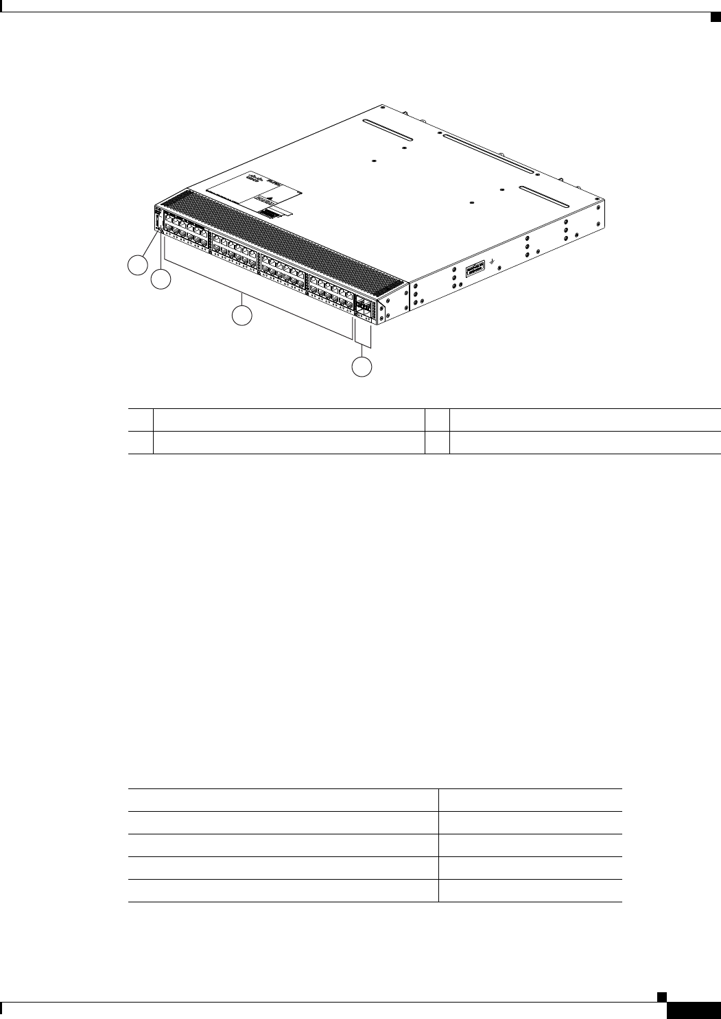
Ports
The Cisco Nexus 2232TM FEX supports a total of 32 10-Gigabit Ethernet ports (SFP+) and 8 10-Gigabit
Ethernet/FCoE uplinks (SFP+). SFP transceivers can also be plugged into the SFP+ cages to allow a
1-Gigabit downlink. The Cisco Nexus 2232TM-10GE provides two types of ports: ports for end-host
attachment and uplink ports. Uplink ports, which are colored yellow, connect to the upstream parent
Cisco Nexus 5000 Series switch.
The Cisco Nexus 2232TM-10GE supports Data Center Bridging (DCB) which increases the reliability,
efficiency, and scalability of Ethernet networks by allowing the switches to support multiple traffic
classes over a lossless Ethernet fabric. These features allow the switches to support multiple traffic
classes over a lossless Ethernet fabric, enabling consolidation of LAN, SAN, and cluster environments.
Figure 1-31 shows the ports on the rear of the Cisco Nexus 2232TM-10GE chassis.
1
2
3
4
330056
1Status and ID LEDs 310-Gigabit Base-T host-facing (downlink)
ports (32)
2HDMI port 410-Gigabit SFP+ ports (8)
1-30
Cisco Nexus 2000 Series Hardware Installation Guide
Chapter 1 Using a Fabric Extender with a Cisco Nexus 5000 Series or Cisco Nexus 6000 Series Switch
Cisco Nexus 2232TM-10GE, Cisco Nexus N2K-C2232TM-E-10GE
Figure 1-31 Ports Located on the Rear of the Cisco Nexus 2232TM-10GE Chassis
Power Supplies
The Cisco Nexus 2232TM-10GE FEX chassis has two bays for fan side AC or DC power supplies. This
chassis is fully functional with one power supply, but you can install a second power supply for power
redundancy. The power supply is hot-swappable during operations.
Table 1-9 lists the power supplies that you can order with the Cisco Nexus 2232TM-10GE FEX.
Figure 1-23 on page 1-20 shows an AC power supply with port-side exhaust airflow. Figure 1-24 on
page 1-21 shows an AC power supply with port-side intake airflow. Figure 1-25 on page 1-21 shows a
DC power supply with port-side exhaust airflow.
You can order the Cisco Nexus 2232TM-10GE FEX with AC power supplies that have port-side exhaust
or port-side intake airflow for cooling or DC power supplies that have port-side exhaust airflow. The
port-side intake airflow components have a black stripe on their fan side surface for easy visual
identification. The port-side exhaust airflow components do not have a black stripe.
Caution Be sure that all of the power supply and fan tray modules in the same chassis have the same airflow
direction and that the air intake for those modules is positioned on a cool aisle. If you install a module
that uses a different direction of airflow from the other modules in your system, you will see an error
message. If you position a chassis with its modules taking cooling air from a warm aisle, the switch can
over heat and shut down.
If one power supply is installed in the chassis, but the other power supply slot is empty, you should use
a blank filler panel (N2200-P-BLNK) to cover the empty slot. Figure 1-26 on page 1-22 shows a blank
power supply filler panel.
3
330057
2
4
1
1Status (top) and ID (bottom) LEDs 332 10-Gigabit BaseT host ports
2HDMI Connector 48 10-Gigabit SFP+ ports
Table 1-9 Power Supplies for the Cisco Nexus 2232TM-10GE FEX
Power Supply Part Number
AC power supply with port-side exhaust airflow N2K-PAC-400W
AC power supply with port-side intake airflow N2K-PAC-400W-B
DC power supply with port-side exhaust airflow N2K-PDC-400W
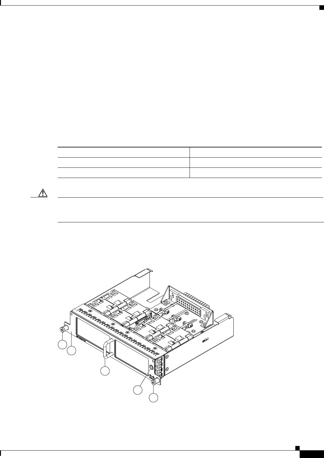
1-31
Cisco Nexus 2000 Series Hardware Installation Guide
Chapter 1 Using a Fabric Extender with a Cisco Nexus 5000 Series or Cisco Nexus 6000 Series Switch
Cisco Nexus 2232TM-10GE, Cisco Nexus N2K-C2232TM-E-10GE
For power supply specifications, see Power Specifications, page B-1. To replace a power supply, see the
“Removing and Installing Power Supplies” section on page 4-16.
For LED descriptions, see “Chassis and Module LEDs for the Cisco Nexus Fabric Extenders”.
Fan Trays
The Cisco Nexus 2232TM-10GE FEX has one fan tray that is hot swappable during operations.
Depending on whether there is a cold aisle in fan side or port side of the chassis, you can order port-side
exhaust airflow or port-side intake airflow for the fan tray and the power supplies in the same chassis.
Table 1-10 lists the part numbers for each of the fan trays that you can use with this chassis.
Caution Always make sure that all of the fan tray and power supply modules have the same direction of airflow
and the same color designation for that airflow direction. The switch does not support having more than
one direction of airflow with its modules.
To see the components used when installing a fan tray, see Figure 1-32 (port-side exhaust airflow) or
Figure 1-33 (port-side intake airflow).
Figure 1-32 Port-Side Exhaust Airflow Fan Tray for the Cisco Nexus 2232TM-10GE FEX
Table 1-10 Fan Trays for the Cisco Nexus 2232TM-10GE FEX
Description Part Number
Port-side exhaust airflow N2K-C2232-FAN
Port-side intake airflow N2K-C2232-FAN-B
4
2
1
3
1
239292
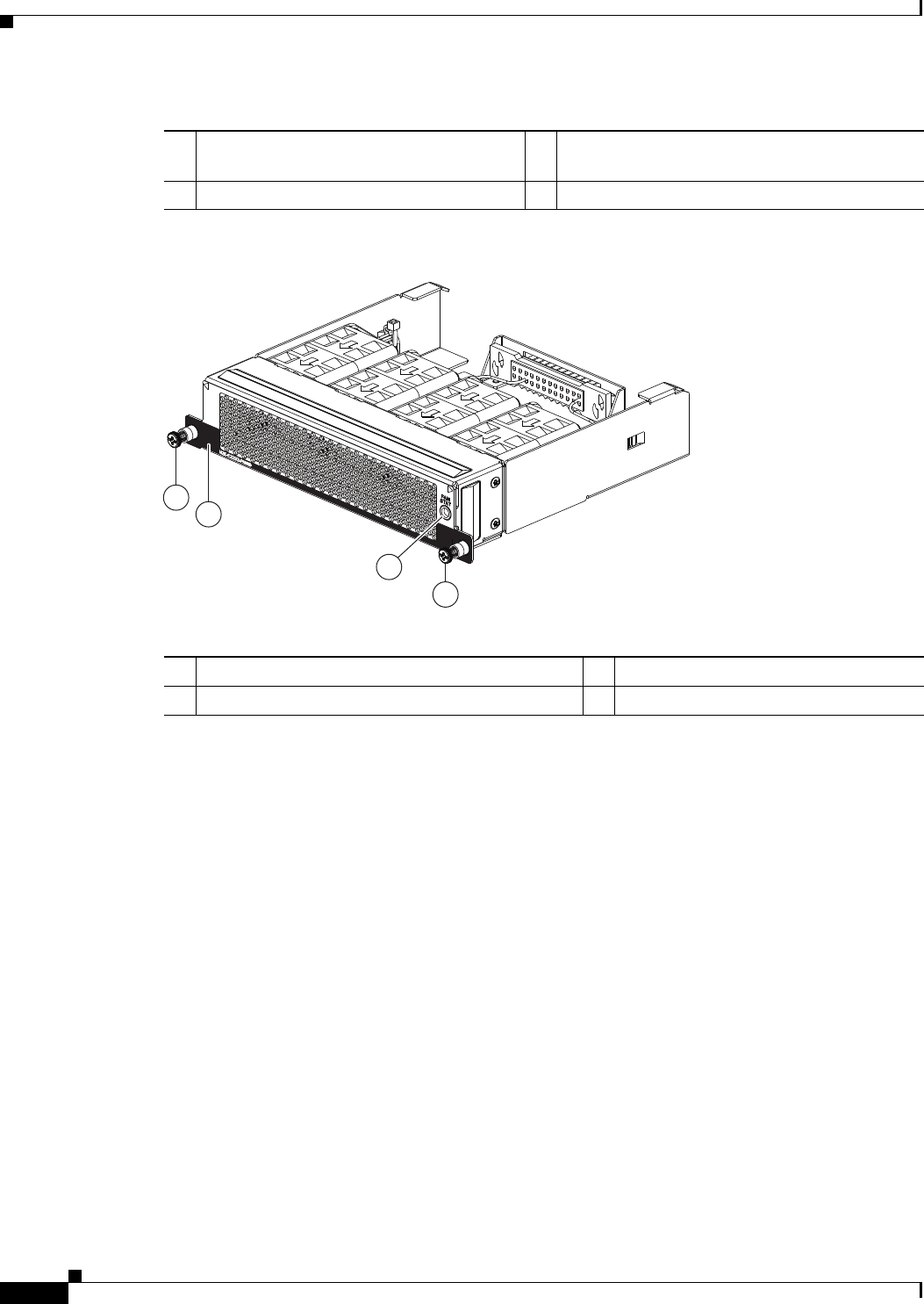
1-32
Cisco Nexus 2000 Series Hardware Installation Guide
Chapter 1 Using a Fabric Extender with a Cisco Nexus 5000 Series or Cisco Nexus 6000 Series Switch
Cisco Nexus 2224TP
Figure 1-33 Port-Side Intake Airflow Fan Tray for the Cisco Nexus 2232TM-10GE FEX
To replace a fan tray, see the “Removing and Installing the Fan Tray” section on page 4-21. For LED
descriptions, see Table E-1 on page E-2.
Supported Transceivers and Cables
The Cisco Nexus 2232TM-10GE Series FEX supports SFP+ Ethernet transceivers. The enhanced
Small-Form-Factor Pluggable (SFP+) 10-Gigabit Ethernet transceiver is a bidirectional device with a
transmitter and receiver. It has a 20-pin connector on the electrical interface and duplex LC connector
on the optical interface. Currently, the FEX supports the short-range SFP and long-range SFP
transceiver. Copper interface cables are available for use with the 10-Gigabit Ethernet SFP+ transceiver.
For an updated list of supported transceivers and optics, please see the Cisco Nexus 2000 Series Fabric
Extenders Release Notes.
Cisco Nexus 2224TP
The Cisco Nexus 2224TP is a stackable 1 RU FEX. This FEX is very similar to the Cisco Nexus 2248TP
except that it has 24 100/1000BASE-T downlink ports, 2 SFP+ uplink ports and you can order it with
port-side exhaust airflow or port-side intake airflow. You can use this FEX with the Cisco Nexus 5000
Series switch. The Cisco Nexus 2224TP is managed and configured by the upstream switch. The FEX
1Captive screws (2) 3No black stripe indicates port-side exhaust
airflow
2 Handle 4Status LED
239936
2
1
3
1
1Captive screws (2) 3Status LED
2 Black stripe indicates port-side intake airflow
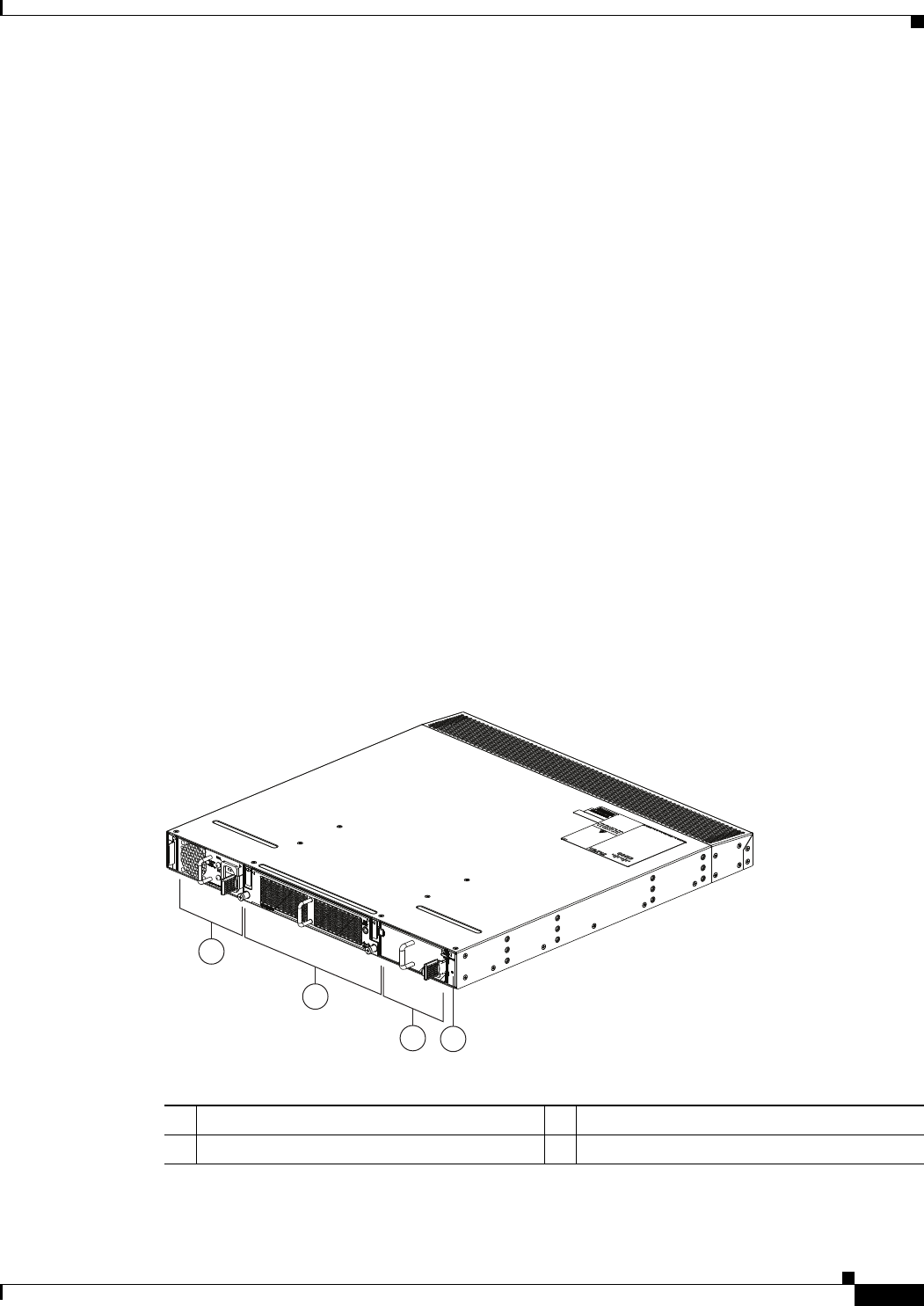
1-33
Cisco Nexus 2000 Series Hardware Installation Guide
Chapter 1 Using a Fabric Extender with a Cisco Nexus 5000 Series or Cisco Nexus 6000 Series Switch
Cisco Nexus 2224TP
software ships with the Cisco Nexus 5000 Series switch software. The FEX downloads the software
image from the switch the same way that a module would download it from the supervisor in a modular
chassis.
This section includes the following topics:
•Chassis, page 1-33
•Ports, page 1-34
•Power Supplies, page 1-34
•Fan Tray, page 1-35
•Supported SFP+ Transceivers, page 1-36
Chassis
The Cisco Nexus 2224TP chassis has a height of 1.72 inches (4.37 cm), a width of 17.34 inches (44.04
cm), and a depth of 18.9 inches (48.1 cm). It weighs 18 pounds (8.0 kg). Its one-rack-unit (1 RU) form
factor takes up relatively little space, making it easy to incorporate into rack designs. The FEX is
mounted in a standard 19-inch (48.26-cm) rack. It has port side exhaust or port side intake airflow for
cooling. All switch ports are located at the rear of the unit in close proximity to server ports, and all
user-serviceable components are accessible from the fan side.
Figure 1-34 shows the location of the components on the fan side of the chassis, and Figure 1-35 shows
the location of components on the rear of the chassis. For information on what the chassis and component
LEDs indicate, see Table E-1 on page E-2.
Figure 1-34 Fan side of the Cisco Nexus 2224TP Chassis
2
1
34
239281
1Power supply 3Power supply (blank power supply shown)
2Fan tray (1) 4Status (top) and ID (bottom) LEDs
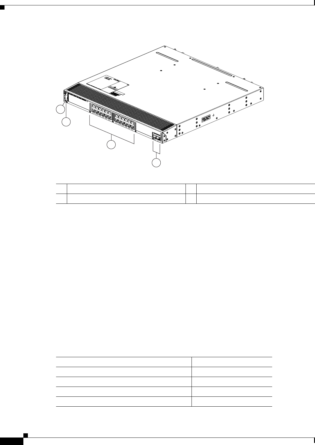
1-34
Cisco Nexus 2000 Series Hardware Installation Guide
Chapter 1 Using a Fabric Extender with a Cisco Nexus 5000 Series or Cisco Nexus 6000 Series Switch
Cisco Nexus 2224TP
Figure 1-35 Rear View of the Nexus 2224TP Chassis
Ports
The Cisco Nexus 2224TP FEX supports a total of 24 100/1000BASE-T downlink ports and two SFP+
uplink ports on the rear panel. There is an HDMI port on the rear panel for console and management port
connectivity. Uplink ports are colored yellow for connectivity to the upstream parent Cisco Nexus 5000
Series switch.
Power Supplies
The Cisco Nexus 2224TP FEX chassis has two bays for fan side AC or DC power supplies (the same
power supplies used for the Cisco Nexus 2248TP). This chassis is fully functional with one power
supply, but you can install a second power supply for power redundancy. The power supply is hot
swappable during operations.
Table 1-11 lists the power supplies that you can order with the Cisco Nexus 2224TP FEX.
3
4
239280
2
1
1Status (top) and ID (bottom) LEDs 3100/1000BASE-T data ports (24)
2HDMI port 4SFP+ uplink ports (2)
Table 1-11 Power Supplies for the Cisco Nexus 2224TP FEX
Power Supply Part Number
AC power supply with port-side exhaust airflow N2200-PAC-400W
AC power supply with port-side intake airflow N2200-PAC-400W-B
DC power supply with port-side exhaust airflow N2200-PDC-400W
DC power supply with port-side intake airflow N2200-PDC-350W-B

1-35
Cisco Nexus 2000 Series Hardware Installation Guide
Chapter 1 Using a Fabric Extender with a Cisco Nexus 5000 Series or Cisco Nexus 6000 Series Switch
Cisco Nexus 2224TP
To see the components that you use when installing a power supply unit, see Figure 1-23 on page 1-20
for the AC power supply with port-side exhaust airflow, Figure 1-24 on page 1-21 for the AC power
supply with port-side intake airflow, and Figure 1-25 on page 1-21 for the DC power supply with
port-side exhaust airflow.
You can order the Cisco Nexus 2224TP FEX with AC power supplies that have port-side exhaust or
port-side intake airflow for cooling or DC power supplies that have port-side exhaust airflow. The
port-side intake airflow components have a black stripe on their fan side surface for easy visual
identification. The port-side exhaust airflow components do not have a black stripe.
Caution Be sure that all of the power supply and fan tray modules in the same chassis have the same airflow
direction and that the air intake for those modules is positioned on a cool aisle. If you install a module
that uses a different direction of airflow from the other modules in your system, you will see an error
message. If you position a chassis with its modules taking cooling air from a warm aisle, the switch can
over heat and shut down.
If one power supply is installed in the chassis, but the other power supply slot is empty, you should use
a blank filler panel to cover the empty slot. Figure 1-26 on page 1-22 shows a blank power supply filler
panel.
For power supply specifications, see Table B-1 on page B-2. To replace a power supply, see the
“Removing and Installing Power Supplies” section on page 4-16.
Fan Tray
The Cisco Nexus 2224TP FEX has one fan tray that is hot swappable during operations. Depending on
whether there is a cold aisle in fan side or port-side of the chassis, you can order port-side exhaust airflow
or port-side intake airflow for the fan tray and the power supplies in the same chassis. Table 1-12 lists
the part numbers for each of the fan trays that you can use with this chassis.
Caution Always make sure that all of the fan tray and power supply modules have the same direction of airflow
and the same color designation for that airflow direction. The switch does not support having more than
one direction of airflow with its modules.
To see the components used when installing one of these fan trays, see Figure 1-27 (port side exhaust
airflow) or Figure 1-28 (port side intake airflow).
To replace a fan tray, see the “Removing and Installing the Fan Tray” section on page 4-21. For LED
descriptions, see Table E-1 on page E-2.
Table 1-12 Fan Trays for the Cisco Nexus 2224TP and 2248TP FEXs
Description Part Number
port side exhaust airflow N2K-C2248-FAN
port side intake airflow N2K-C2248-FAN-B

1-36
Cisco Nexus 2000 Series Hardware Installation Guide
Chapter 1 Using a Fabric Extender with a Cisco Nexus 5000 Series or Cisco Nexus 6000 Series Switch
Cisco Nexus 2148T
Supported SFP+ Transceivers
The Cisco Nexus 2224TP FEX supports SFP+ Ethernet transceivers. The enhanced Small-Form-Factor
Pluggable (SFP+) 10-Gigabit Ethernet transceiver is a bidirectional device with a transmitter and
receiver. It has a 20-pin connector on the electrical interface and duplex LC connector on the optical
interface. Currently, the Cisco Nexus 2224TP FEX supports the short-range SFP and long-range SFP
transceiver. Copper interface cables are available for use with the 10-Gigabit Ethernet SFP+ transceiver.
For an updated list of supported transceivers and optics, please see the Cisco Nexus 2000 Series Fabric
Extenders Release Notes.
Cisco Nexus 2148T
The Cisco Nexus 2148T FEX is a 1 RU device that acts as a remote I/O module on the Cisco Nexus 5000
Series switch. All device configurations are managed on the switch and configuration information is
downloaded through inband communication to the FEX. You can use this FEX with the Cisco Nexus
5000 Series switch. The FEX software ships with the Cisco Nexus 5000 Series switch software. The FEX
downloads the software image from the switch the same way that a module would download it from the
supervisor in a modular chassis.
This section includes the following topics:
•Features, page 1-36
•Chassis, page 1-36
•Ports, page 1-38
•Power Supplies, page 1-38
•Fan Tray, page 1-39
•Supported SFP Transceivers, page 1-40
Features
The Cisco Nexus 2148T FEX has the following features:
•Forty-eight 1-Gigabit Ethernet ports
•Four 10-Gigabit Ethernet ports
•Redundant (dual) 200-W modular, hot-swappable power supplies with a power switch on each
supply
•Removable fan tray with redundant fans. The fan tray can be removed for hot swapping. If it is not
replaced within 60 seconds, the system shuts down.
•Port-side exhaust airflow
Chassis
The Cisco Nexus 2148T FEX has a height of 1.72 inches (4.37 cm), a width of 17.3 inches (43.94 cm),
and a depth of 20 inches (50.8 cm). The FEX is mounted in a standard 19-inch (48.24 cm) rack. The
chassis requires 1 RU. One fan tray and two power supplies are located at the fan side of the device. The
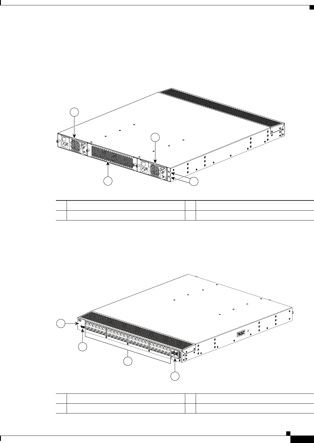
1-37
Cisco Nexus 2000 Series Hardware Installation Guide
Chapter 1 Using a Fabric Extender with a Cisco Nexus 5000 Series or Cisco Nexus 6000 Series Switch
Cisco Nexus 2148T
ports are located at the rear of the device. The chassis has port-side exhaust airflow with cool air entering
the chassis through the fan tray and power supply modules and exhausting through the port side of the
chassis.
Figure 1-36 identifies the features on the fan side of the Cisco Nexus 2148T FEX.
Figure 1-36 Fan side view of the Cisco Nexus 2148T FEX
The rear of the Cisco Nexus 2148T FEX has 48 1-Gigabit Ethernet ports, 4 10-Gigabit Ethernet ports,
and status and ID LEDs. Figure 1-37 identifies the components found on the rear of the Cisco Nexus
2148T FEX.
Figure 1-37 Rear View of the Cisco Nexus 2148T FEX
273914
1
1
23
1Power supply (two) 3Status (top) and ID (bottom) LEDs
2Fan tray (1)
273916
3
2
1
4
1System status (top) and Beacon (bottom) LED 31-Gigabit Ethernet downlink ports (48)
2 HDMI port 410-Gigabit Ethernet uplink ports (4)
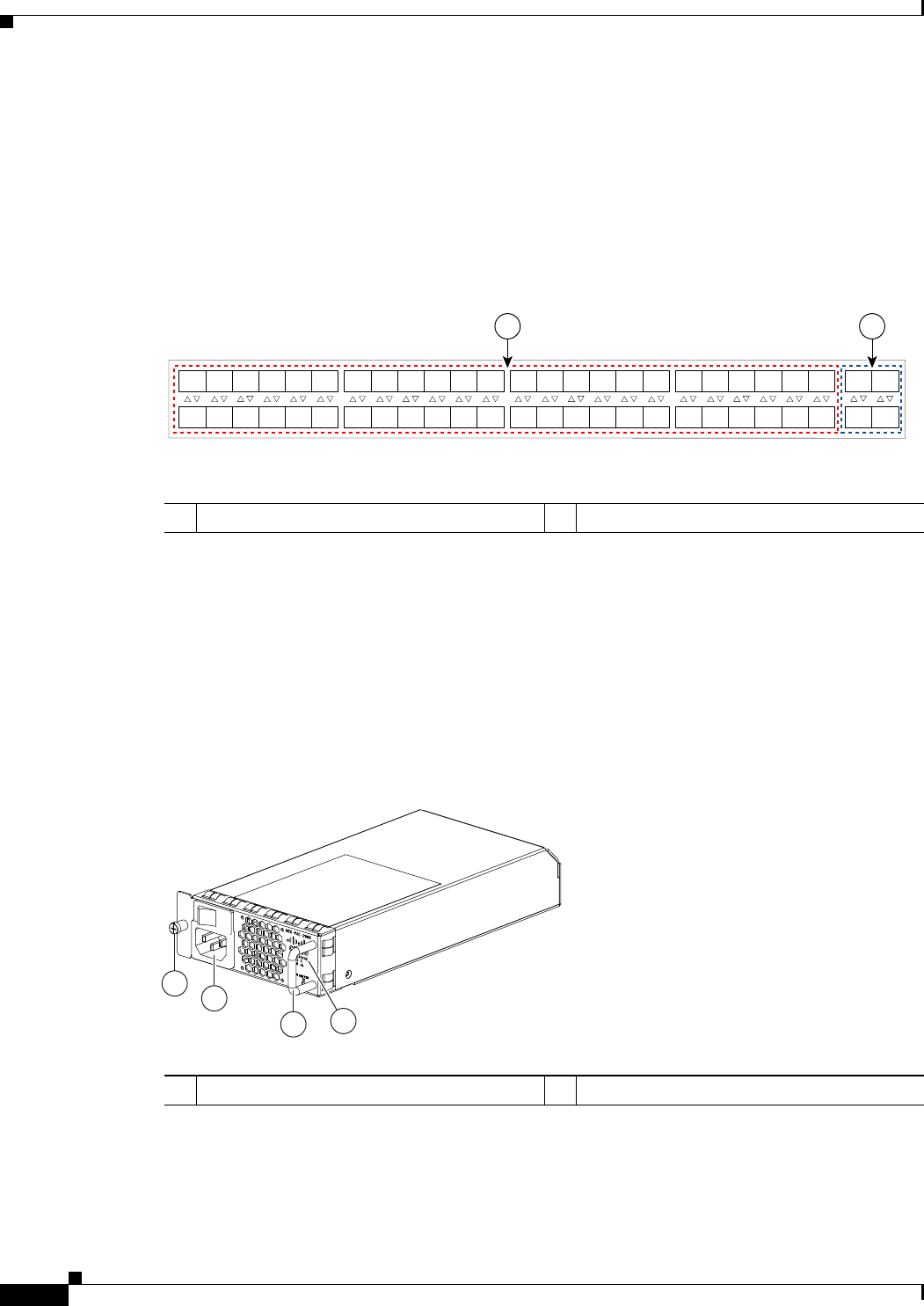
1-38
Cisco Nexus 2000 Series Hardware Installation Guide
Chapter 1 Using a Fabric Extender with a Cisco Nexus 5000 Series or Cisco Nexus 6000 Series Switch
Cisco Nexus 2148T
Ports
Each port on the Cisco Nexus 2148T FEX is numbered, and groups of ports are numbered based on their
function. The ports are numbered from top to bottom and left to right.
Group 1 includes 48 1-Gigabit Ethernet data ports. Group 2 includes four 10-Gigabit Ethernet ports.
Figure 1-38 shows how ports are numbered and grouped by function.
Figure 1-38 Port Numbering on the Cisco Nexus 2148T FEX
Power Supplies
The Cisco Nexus 2148T FEX uses a fan side 200-W AC power supply that has port-side exhaust airflow.
The chassis has two bays for two power supplies. Two power supplies can be used for redundancy, but
the Cisco Nexus 2148T FEX is fully functional with one power supply. Figure 1-39 shows the power
supply with two LEDs: one for power status and one for a failure condition. The power supply is
hot-swappable. For details on how to install a power supply, see the “Removing and Installing Power
Supplies” section on page 4-16.
Figure 1-39 AC Power Supply for the Cisco Nexus 2148T Series FEX
If one power supply is installed in the chassis, but the other power supply slot is empty, you should use
a blank filler panel to cover the empty slot. Figure 1-40 shows a blank power supply filler panel.
A B
192533
1
2
3
4
5
6
7
8
9
10
11
12
13
14
15
16
17
18
19
20
21
22
23
24
25
26
27
28
29
30
31
32
33
34
35
36
37
38
39
40
41
42
43
44
45
46
47
48
1
2
3
4
1Group 1: Data ports 1 through 48 2Group 2: Uplink ports 1 through 4
239274
1
2
34
1Green power LED indicates the power status. 2Amber fail LED indicates a failure condition.
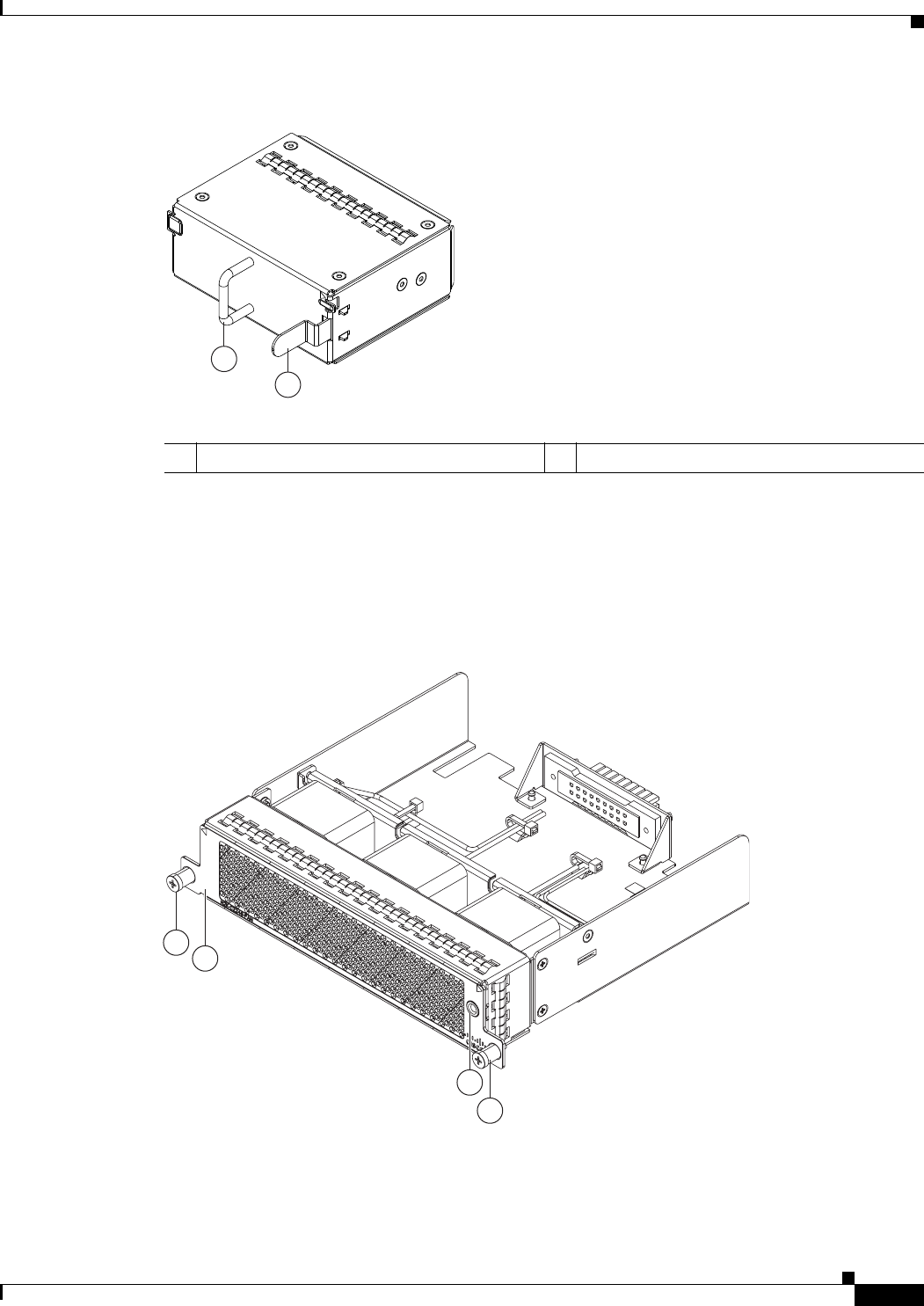
1-39
Cisco Nexus 2000 Series Hardware Installation Guide
Chapter 1 Using a Fabric Extender with a Cisco Nexus 5000 Series or Cisco Nexus 6000 Series Switch
Cisco Nexus 2148T
Figure 1-40 Blank Power Supply Filler Panel
Fan Tray
The Cisco Nexus 2148T FEX has one fan tray that has port-side exhaust airflow. Figure 1-41 shows the
fan tray. The fan tray is hot-swappable as long as you replace it within 60 seconds.
Figure 1-41 Port-Side Exhaust Airflow Fan Tray for Cisco Nexus 2148T FEX
2
1
239290
1Handle 2Ejector latch
3
2
1
1
239291

1-40
Cisco Nexus 2000 Series Hardware Installation Guide
Chapter 1 Using a Fabric Extender with a Cisco Nexus 5000 Series or Cisco Nexus 6000 Series Switch
Cisco Nexus 2148T
Supported SFP Transceivers
The Cisco Nexus 2148T FEX supports SFP+ Ethernet transceivers. The enhanced Small-Form-Factor
Pluggable (SFP+) 10-Gigabit Ethernet transceiver is a bidirectional device with a transmitter and
receiver. It has a 20-pin connector on the electrical interface and duplex LC connector on the optical
interface. Currently, the FEX supports the short-range SFP and long-range SFP transceiver. Copper
interface cables are available for use with the 10-Gigabit Ethernet SFP+ transceiver. For an updated list
of supported transceivers and optics, please see the Cisco Nexus 2000 Series Fabric Extenders Release
Notes.
1Captive screws (2) 2Status LED
3No black stripe indicates port-side exhaust
airflow

CHAPTER
2-1
Cisco Nexus 2000 Series Hardware Installation Guide
2
Using a Fabric Extender with a Cisco Nexus 7000
Series Switch
This chapter describes the Cisco Nexus 2200 Platform Fabric Extender (FEX) chassis and the
components that you can connect to a Cisco Nexus 7000 Series switch. This chapter includes the
following sections:
•Information About Using a Fabric Extender with a Cisco Nexus 7000 Series Switch, page 2-1
•Cisco Nexus 2248TP-E FEX, page 2-2
•Cisco Nexus 2248TP FEX, page 2-11
•Cisco Nexus 2232TM FEX, page 2-15
•Cisco Nexus 2232PP FEX, page 2-22
•Cisco Nexus 2224TP FEX, page 2-27
Information About Using a Fabric Extender with a Cisco Nexus
7000 Series Switch
You can extend the Cisco Nexus 7000 Series switch architecture by connecting up to 32 FEXs as remote
I/O modules. Depending on which FEX model that you connect to the switch, the FEX provides
top-of-the-rack connectivity for up to 48, 32, or 24 hosts, and it becomes an extension of the parent Cisco
Nexus 7000 Series switch fabric, with the FEX and the switch becoming a virtual modular system. The
FEX forwards all 100/1000 Ethernet or 1- and 10-Gigabit Ethernet traffic from the hosts to the switch
over 10-Gbps uplinks. Traffic flows from the switch to the FEX over the 10-Gbps uplinks and to the
individual hosts over 100/1000 Ethernet or 1- and 10-Gigabit Ethernet downlinks.
You connect a FEX uplink port to the Cisco Nexus 7000 Series switch through one of the following
Ethernet I/O modules installed in the switch:
•F2 Series 48-port 1 or 10-Gigabit Ethernet I/O module (N7K-F248XP-25)
•M1 Series 32-port 10-Gigabit Ethernet I/O module (N7K-M132XP-12)
•M1 Series 32-port 10-Gigabit Ethernet I/O module with XL option (N7K-M132XP-12L)
•M2 Series 24-port 10-Gigabit Ethernet I/O module (N7K-M224XP-23L)

2-2
Cisco Nexus 2000 Series Hardware Installation Guide
Chapter 2 Using a Fabric Extender with a Cisco Nexus 7000 Series Switch
Cisco Nexus 2248TP-E FEX
Cisco Nexus 2248TP-E FEX
The Cisco Nexus 2248TP-E FEX (N2K-C2248TP-E) is a stackable 1-RU FEX that has 48 100/1000
Ethernet host-facing (downlink) ports and four 10-Gigabit Ethernet network-facing (uplink) ports. It
requires a 19-inch (48.26 cm) rack for its installation. Table 2-1 lists its physical characteristics.
You can order the Cisco Nexus 2248TP-E with port-side exhaust or back-to-front airflow and with AC
or DC power supplies. If you are going to install the port side in a hot aisle, then order port-side exhaust
airflow for all of the fan trays and power supplies. If you are going to install the port side in the cold
aisle, order port-side intake airflow for the fan trays and power supplies.
Note For visual identification, port-side exhaust airflow power supplies and fan trays have a black stripe
across their front, and port-side intake airflow modules do not have a black stripe across their front. All
of the power supplies and fan trays must have the same direction of airflow for the components to
properly function (all of these components must either have a black stripe or all of the components must
not have a black stripe).
The front of the Cisco Nexus 2248TP-E FEX chassis has one or two power supplies, a fan tray, and two
chassis LEDs as shown in Figure 2-1. This FEX model requires one power supply, but if you want power
redundancy, you must install a second power supply.
Table 2-1 Physical Characteristics for the Cisco Nexus 2248TP-E FEX
Dimensions
Width
Depth
Height
17.3 inches (43.9 cm)
20.0 inches (50.8 cm)
1.72 inches (4.4 cm)
Weight117.7 lb (8.0 kg)
1. Measured with two power supplies and one fan module installed.
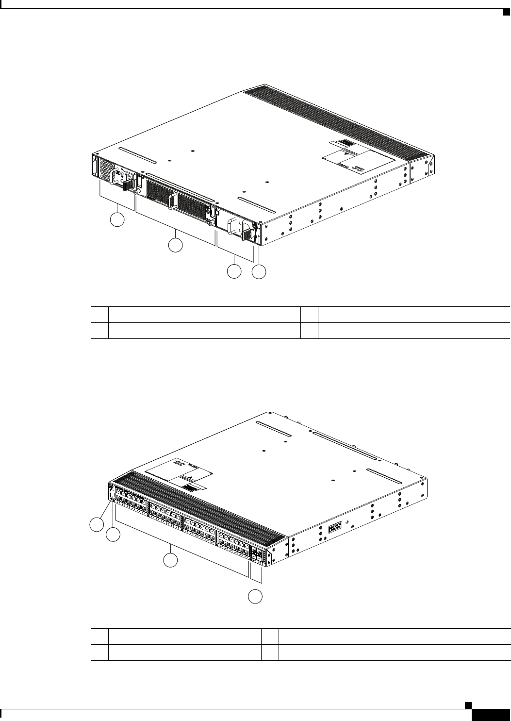
2-3
Cisco Nexus 2000 Series Hardware Installation Guide
Chapter 2 Using a Fabric Extender with a Cisco Nexus 7000 Series Switch
Cisco Nexus 2248TP-E FEX
Figure 2-1 Front View of the Cisco Nexus 2248TP-E Chassis
The rear of the Cisco Nexus 2248TP-E FEX chassis has 48 100/1000 Ethernet downlink ports, four
10-Gigabit Ethernet uplink ports, an HDMI port, and LEDs, as shown in Figure 2-2.
Figure 2-2 Rear View of the Cisco Nexus 2248TP-E Chassis
2
1
34
239288
1Power supply 3Power supply (blank shown)
2Fan tray 4Status (top) and ID (bottom) LEDs
3
2
4
1
239287
1Status (top) and ID (bottom) LEDs 3100/1000 Ethernet host-facing (downlink) ports (48)
2HDMI port 410-Gigabit Ethernet network-facing (uplink) ports (4)
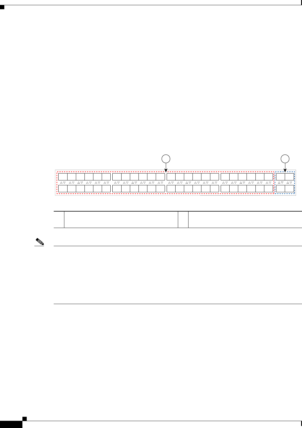
2-4
Cisco Nexus 2000 Series Hardware Installation Guide
Chapter 2 Using a Fabric Extender with a Cisco Nexus 7000 Series Switch
Cisco Nexus 2248TP-E FEX
For LED descriptions, see Appendix E, “LEDs.”
This section includes the following topics:
•Ports for the Cisco Nexus 2248TP-E FEX, page 2-4
•Power Supplies for the Cisco Nexus 2248TP-E FEX, page 2-4
•Fan Tray for the Cisco Nexus 2248TP-E FEX, page 2-7
•Transceivers and Connectors Supported by the Cisco Nexus 2248TP-E FEX, page 2-9
Ports for the Cisco Nexus 2248TP-E FEX
The downlink and uplink ports are numbered from top to bottom and then left to right as shown in
Figure 2-3.
Figure 2-3 Port Numbering on the Cisco Nexus 2248TP-E FEX
Note For a fully dedicated 10-Gbps bandwidth through a M1 Series 32-port 10-Gigabit Ethernet I/O module
(either the N7K-M132XP-12 or N7K-M132XP-12L), connect each FEX to one port in a set of four
shared ports on the module (you connect each set of shared ports to one FEX). If you are using the M2
Series 24-port, 10-Gigabit Ethernet I/O module (N7K-M224XP-23L), you can connect the FEX to any
of its ports for a fully dedicated bandwidth. If you are using the F2 Series 48-port, 10-Gigabit Ethernet
I/O module (N7K-F248XP-25), use the connectivity rule order (connect the same port numbers for each
port group (for example, if you connect ports 1 and 2 of a port-group, then connect the same ports of
another port group).
For information about the transceivers and connectors that you can use with these ports, see the
“Transceivers and Connectors Supported by the Cisco Nexus 2248TP-E FEX” section on page 2-9.
Power Supplies for the Cisco Nexus 2248TP-E FEX
The Cisco Nexus 2200 Series FEX chassis have two slots for front-end AC or DC power supplies that
have port-side exhaust or port-side intake airflow. These chassis are fully functional with one power
supply, but you can install a second power supply for power redundancy. If you have only one power
supply in the chassis, install a blank filler panel (N2200-P-BLNK) to maintain the designed airflow in
the chassis. You can install any of the following power supplies in those two bays:
•AC power supply with port-exhaust airflow (N2200-PAC-400W)
A B
192533
1
2
3
4
5
6
7
8
9
10
11
12
13
14
15
16
17
18
19
20
21
22
23
24
25
26
27
28
29
30
31
32
33
34
35
36
37
38
39
40
41
42
43
44
45
46
47
48
1
2
3
4
A100/1000 Ethernet downlink ports, numbered
1 through 48
B10-Gigabit Ethernet uplink ports, numbered 1
through 4
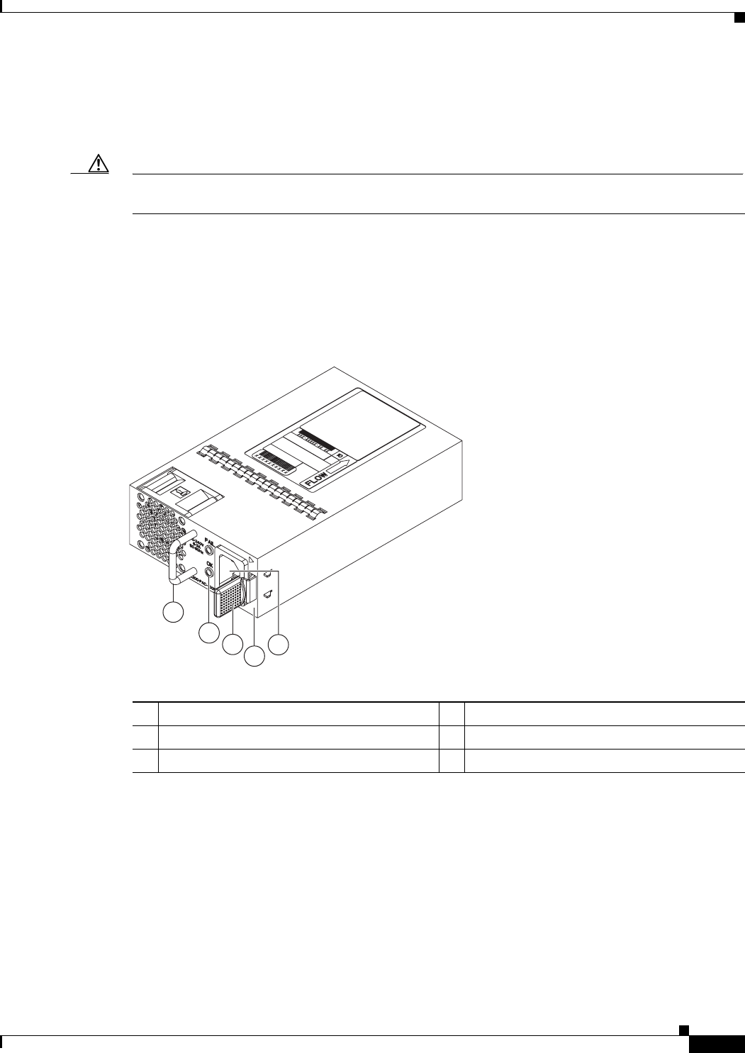
2-5
Cisco Nexus 2000 Series Hardware Installation Guide
Chapter 2 Using a Fabric Extender with a Cisco Nexus 7000 Series Switch
Cisco Nexus 2248TP-E FEX
•AC power supply with port-side intake airflow (N2200-PAC-400W-B)
•DC power supply with port-side exhaust airflow (N2200-PDC-400W)
•DC power supply with port-side intake airflow (N2200-PDC-350W-B)
Caution Make sure that all of the fan tray and power supply modules use the same airflow direction and have the
same color designation on the front. Otherwise, the switch can over heat and shut down,
Figure 2-4 shows the exterior components on an AC power supply with port-side exhaust airflow (no
black stripe on the front). Figure 2-5 shows the components on a DC power supply with port-side exhaust
airflow. Figure 2-6 shows the black stripe used to indicate port-side intake airflow (in this case on an AC
power supply). Figure 2-7 shows the blank filler panel that you should install in an open power supply
slot if the chassis has only one power supply.
Figure 2-4 AC Power Supply with Port-Side Exhaust Airflow for the Cisco Nexus 2200 Platform
1
2
3
4
5
239843
1Handle 4No black stripe (port-side exhaust airflow)
2FAIL (top) and OK (bottom) LEDs 5AC power receptacle
3Ejector latch
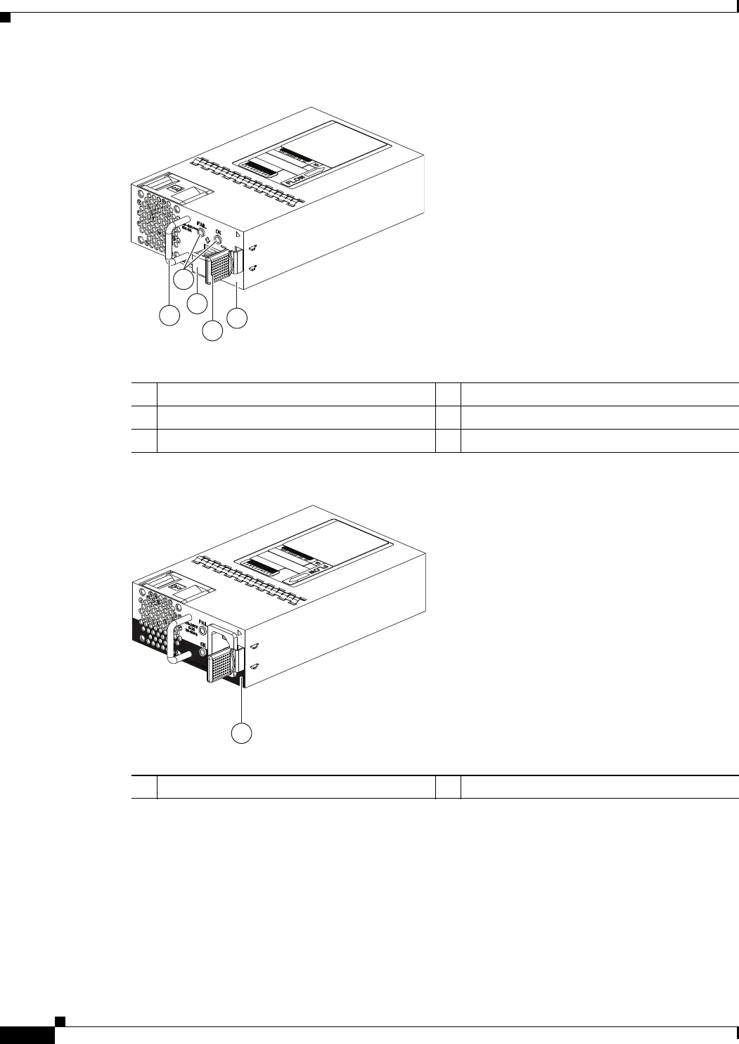
2-6
Cisco Nexus 2000 Series Hardware Installation Guide
Chapter 2 Using a Fabric Extender with a Cisco Nexus 7000 Series Switch
Cisco Nexus 2248TP-E FEX
Figure 2-5 DC Power Supply with Port-Side Exhaust Airflow for the Cisco Nexus 2200 Platform
Figure 2-6 Black Stripe Used to Indicate Port-Side Intake Airflow
1
2
4
3
5
239933
1Handle 4Ejector latch
2FAIL (left) and OK (right) LEDs 5No black stripe (port-side exhaust airflow)
3DC power connector with safety cover
1
334329
A220 P C-400
1Black stripe (port-side intake airflow)
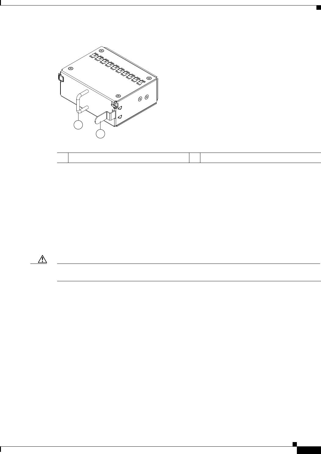
2-7
Cisco Nexus 2000 Series Hardware Installation Guide
Chapter 2 Using a Fabric Extender with a Cisco Nexus 7000 Series Switch
Cisco Nexus 2248TP-E FEX
Figure 2-7 Blank Power Supply Filler Panel for a Cisco Nexus 2200 Platform Power Supply Bay
For LED descriptions, see Appendix E, “LEDs”.
For power supply specifications, see Appendix B, “Technical Specifications”.
Fan Tray for the Cisco Nexus 2248TP-E FEX
The Cisco Nexus 2224TP, 2248TP, and 2248TP-E FEXs use the same fan tray that you can order with
either port-side exhaust airflow (N2K-C2248-FAN) or port-side intake airflow (N2K-C2248-FAN-B).
The fan tray includes a status LED that indicates whether the module is operational. You can hot swap
the fan tray during operations.
Caution Make sure that all of the fan tray and power supply modules use the same airflow direction and have the
same color designation on the front. Otherwise, the switch can over heat and shut down,
Figure 2-8 shows the fan tray with port-side exhaust airflow (no black stripe on front) and identifies its
components, and Figure 2-9 shows the fan tray with port-side intake airflow (black stripe on front) and
identifies its components.
2
1
239290
1Handle 2Ejector latch
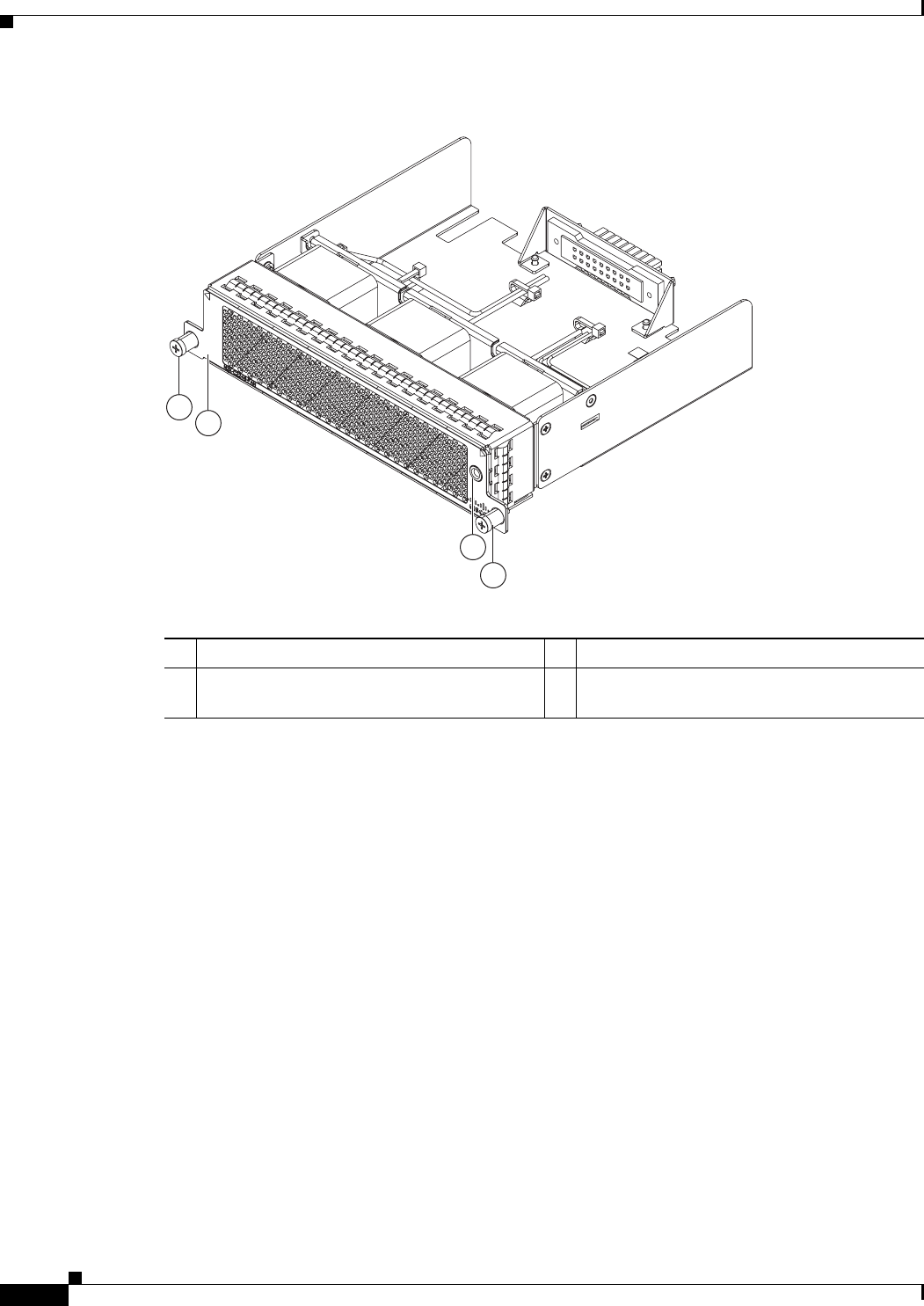
2-8
Cisco Nexus 2000 Series Hardware Installation Guide
Chapter 2 Using a Fabric Extender with a Cisco Nexus 7000 Series Switch
Cisco Nexus 2248TP-E FEX
Figure 2-8 Port-Side Exhaust Airflow Fan Tray for the Cisco Nexus 2000 Series FEX
3
2
1
1
239291
1Captive screws (2) 3Status LED
2No black stripe on the front indicates that this
fan tray has port-side exhaust airflow.
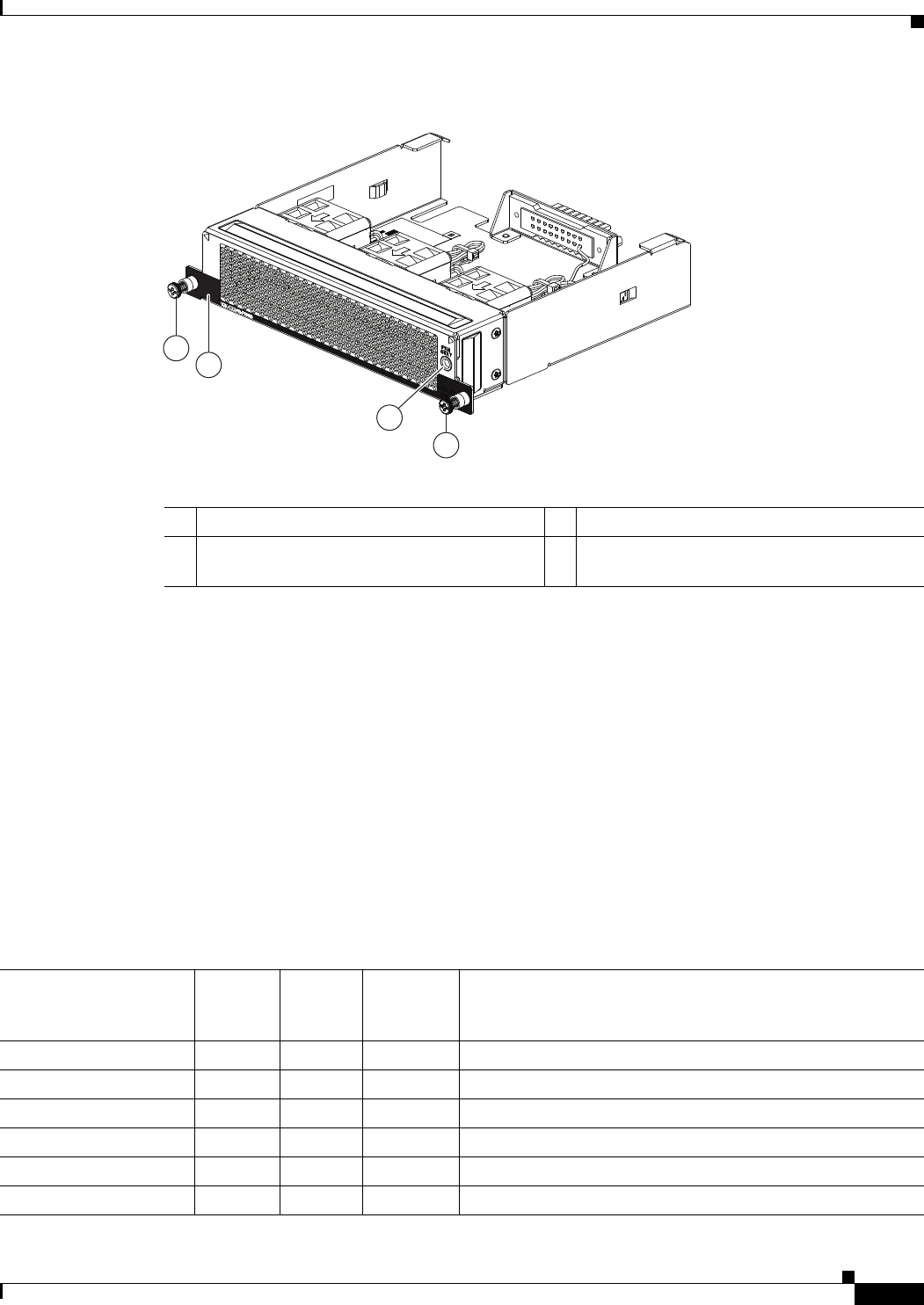
2-9
Cisco Nexus 2000 Series Hardware Installation Guide
Chapter 2 Using a Fabric Extender with a Cisco Nexus 7000 Series Switch
Cisco Nexus 2248TP-E FEX
Figure 2-9 Port-Side Intake Airflow Fan Tray for the Cisco Nexus 2000 Series FEX
For information on this fan tray, see the “Fan Tray for the Cisco Nexus 2248TP FEX” section on
page 2-14 and the fan tray specifications in Appendix B, “Technical Specifications”. For LED
descriptions, see Appendix E, “LEDs”. To replace one of these fan trays, see the “Removing and
Installing the Fan Tray” section on page 4-21.
Transceivers and Connectors Supported by the Cisco Nexus 2248TP-E FEX
The Cisco Nexus 2248TP-E FEX supports SFP+ Ethernet optical and copper transceivers and optical
FEX Transceivers (FETs) for up to four fabric uplink connections to Cisco Nexus 7000 Series switches,
and it supports RJ-45 connectors for up to 48 downlink connections to hosts. For each uplink cable, you
must use the same transceiver on both ends. Table 2-2 lists the transceivers supported by this FEX for
its uplink fabric.
2
1
3
239934
1
1Captive screws (2) 3Status LED
2Black stripe on the front indicates that this fan
tray has port-side intake airflow.
Table 2-2 Supported Transceivers and Connector for the Cisco Nexus 2248TP-E FEX Uplink Interfaces
Transceiver or
Connector
Cable
Type
Fabric
Interface
(Uplink)
Host
Interface
(Downlink) Comments
FET-10G Optical X – 10 Gbps FEX transceiver
SFP-10G-LR Optical X – 10 Gbps long range transceiver (up to 6.2 miles [10 km])
SFP-10G-SR Optical X – 10 Gbps Short range transceiver (up to 984 feet [300 m])
SFP -H10GB-CU1M Copper X – 10 Gbps Twinax, passive transceiver (3.3 feet [1 meter])
SFP -H10GB-CU3M Copper X – 10 Gbps Twinax, passive transceiver (9.8 feet [3 meters)
SFP -H10GB-CU5M Copper X – 10 Gbps Twinax, passive transceiver (16.4 feet [5 meters])
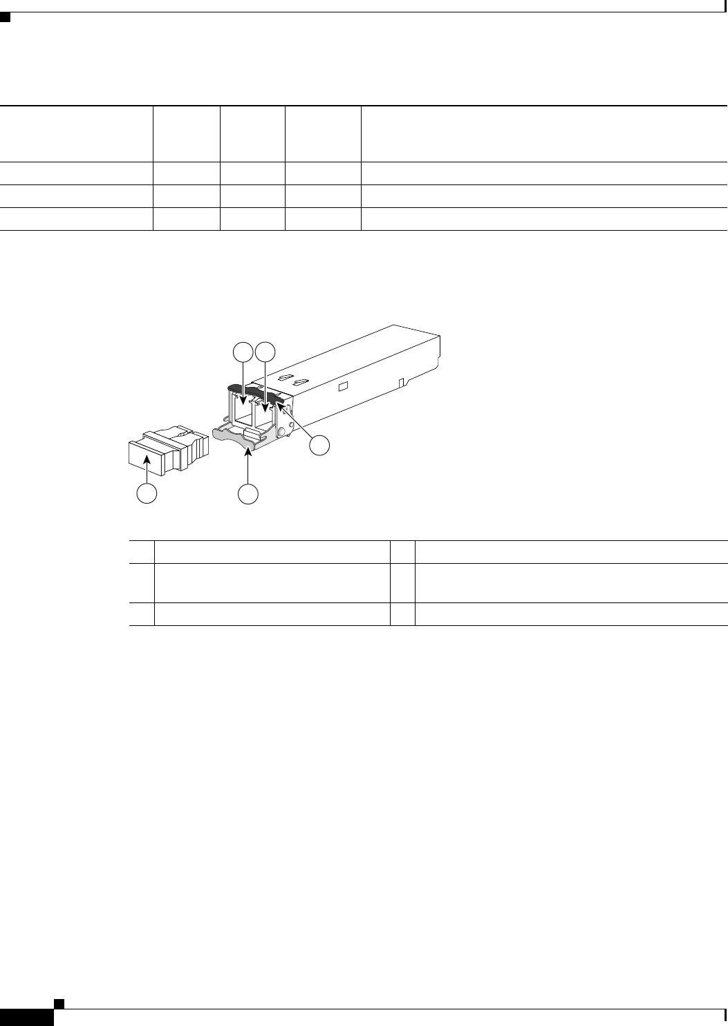
2-10
Cisco Nexus 2000 Series Hardware Installation Guide
Chapter 2 Using a Fabric Extender with a Cisco Nexus 7000 Series Switch
Cisco Nexus 2248TP-E FEX
Figure 2-10 shows the SFP+ optical transceiver used for uplink connections.
Figure 2-10 SFP+ Optical Transceivers and FETs
Figure 2-11 identifies the major features of the SFP+ copper transceiver and cable used for uplink
connections.
SFP -H10GB-ACU7M Copper X – 10 Gbps Twinax, active transceiver (23.0 feet [7 meters])
SFP -H10GB-ACU10M Copper X – 10 Gbps Twinax, active transceiver (32.8 feet [10 meters])
RJ-45 Copper – X 100/1000 Mbps Connector
Table 2-2 Supported Transceivers and Connector for the Cisco Nexus 2248TP-E FEX Uplink Interfaces
Transceiver or
Connector
Cable
Type
Fabric
Interface
(Uplink)
Host
Interface
(Downlink) Comments
197285
12
54
3
1Receive optical bore 4Clasp shown in open position
2Transmit optical bore 5Dust plug (use this to protect the bores from dust
contamination when the optical cables are removed)
3Clasp shown in closed position
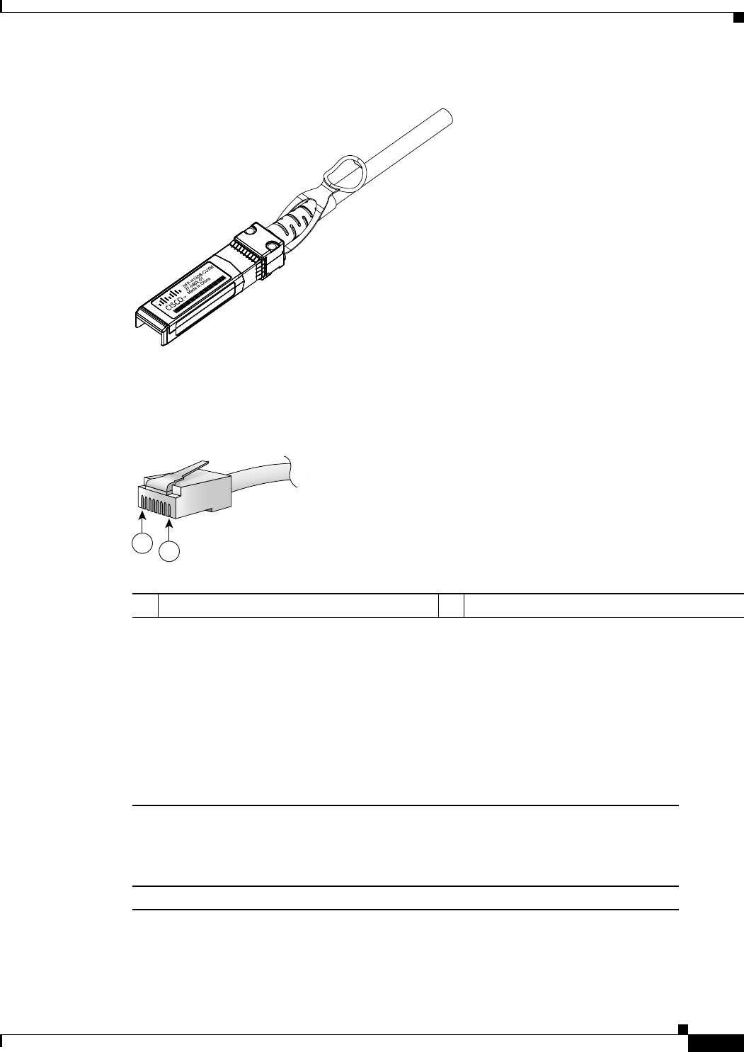
2-11
Cisco Nexus 2000 Series Hardware Installation Guide
Chapter 2 Using a Fabric Extender with a Cisco Nexus 7000 Series Switch
Cisco Nexus 2248TP FEX
Figure 2-11 SFP+ Copper Transceiver Module
Figure 2-12 identifies the major features of RJ-45 connectors, which are used for the downlink
connections.
Figure 2-12 RJ-45 Connector
Cisco Nexus 2248TP FEX
The Cisco Nexus 2248TP FEX is a stackable 1-RU FEX that has 48 100/1000 Ethernet host-facing
(downlink) ports and four 10-Gigabit Ethernet network-facing (uplink) ports. It requires a 19-inch (48.26
cm) rack for its installation. Table 2-3 lists its physical characteristics.
187492
94971
12
RJ-45 (both ends)
1Pin 1 2Pin 8
Table 2-3 Physical Characteristics for the Cisco Nexus 2248TP FEX
Dimensions
Width
Depth
Height
17.3 inches (43.9 cm)
20.0 inches (50.8 cm)
1.72 inches (4.4 cm)
Weight117.7 lb (8.0 kg)
1. Measured with two power supplies and one fan module installed.
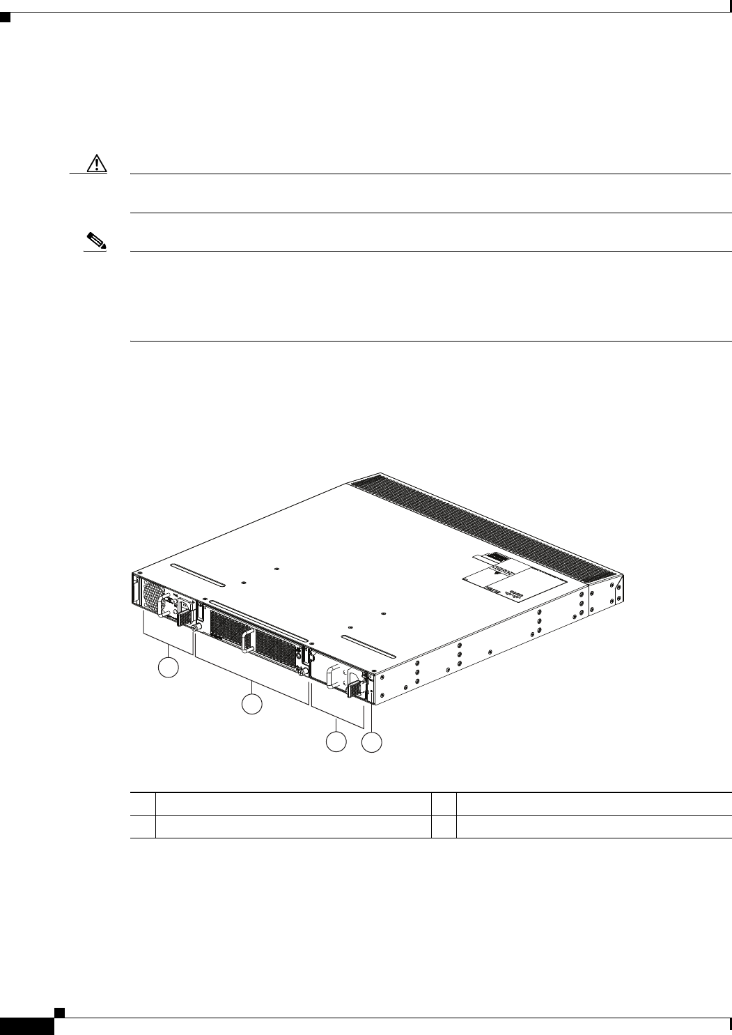
2-12
Cisco Nexus 2000 Series Hardware Installation Guide
Chapter 2 Using a Fabric Extender with a Cisco Nexus 7000 Series Switch
Cisco Nexus 2248TP FEX
You can order the Cisco Nexus 2248TP with port-side exhaust or port-side intake airflow and with AC
or DC power supplies. If you are going to install the ports in a hot aisle, then order port-side exhaust
airflow for all of the fan trays and power supplies. If you are going to install the ports in the cold aisle,
order port-side intake airflow for all of the fan trays and power supplies.
Caution Make sure that all of the fan tray and power supply modules use the same airflow direction and have the
same color designation on the front. Otherwise, the switch can over heat and shut down,
Note For visual identification, port-side exhaust airflow fan trays and power supplies have a black stripe
across their front, and port-side intake airflow modules do not have a black stripe across their front. All
of the power supplies and fan trays must have the same direction of airflow for the components to
properly function (all of these components must either have a black stripe or all of the components must
not have a black stripe).
The front of the Cisco Nexus 2248TP FEX chassis has one or two power supplies, a fan tray, and two
chassis LEDs as shown in Figure 2-13. This FEX model requires one power supply, but if you want
power redundancy, you must install a second power supply.
Figure 2-13 Front View of the Cisco Nexus 2248TP Chassis
The rear of the Cisco Nexus 2248TP-E FEX has 48 100/1000 Ethernet downlink ports, four 10-Gigabit
Ethernet uplink ports, an HDMI port, and LEDs, as shown in Figure 2-14.
2
1
34
239288
1Power supply 3Power supply (blank shown)
2Fan tray 4Status (top) and ID (bottom) LEDs
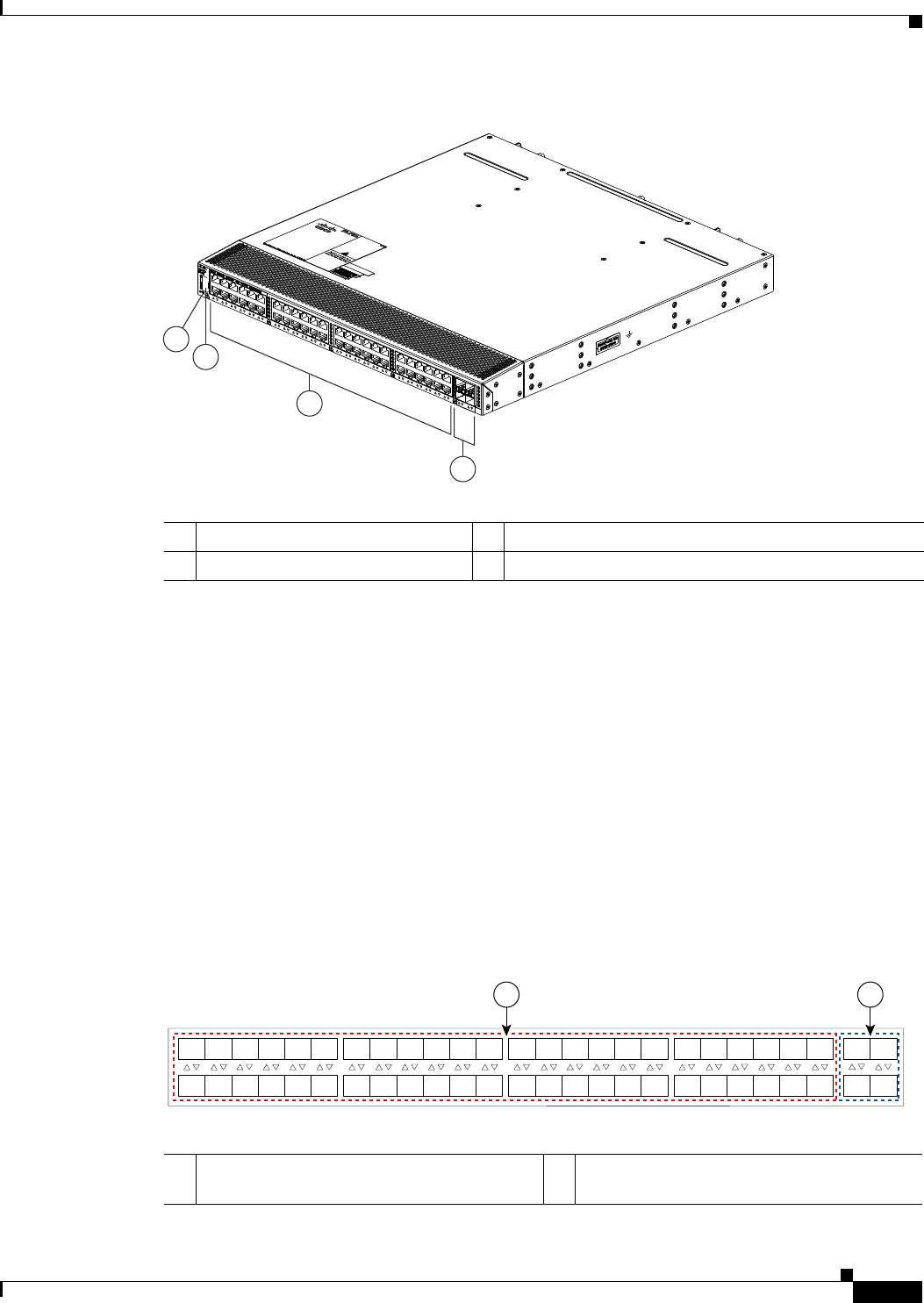
2-13
Cisco Nexus 2000 Series Hardware Installation Guide
Chapter 2 Using a Fabric Extender with a Cisco Nexus 7000 Series Switch
Cisco Nexus 2248TP FEX
Figure 2-14 Rear View of the Cisco Nexus 2248TP Chassis
For LED descriptions, see Appendix E, “LEDs.”
This section includes the following topics:
•Ports for the Cisco Nexus 2248TP FEX, page 2-13
•Power Supplies for the Cisco Nexus 2248TP FEX, page 2-14
•Fan Tray for the Cisco Nexus 2248TP FEX, page 2-14
•Transceivers and Connectors Supported by the Cisco Nexus 2248TP FEX, page 2-14
Ports for the Cisco Nexus 2248TP FEX
The downlink and uplink ports are numbered from top to bottom and then left to right as shown in
Figure 2-15.
Figure 2-15 Port Numbering on the Cisco Nexus 2248TP FEX
3
2
4
1
239287
1Status (top) and ID (bottom) LEDs 3100/1000 Ethernet host-facing (downlink) ports (48)
2HDMI port 410-Gigabit Ethernet network-facing (uplink) ports (4)
A B
192533
1
2
3
4
5
6
7
8
9
10
11
12
13
14
15
16
17
18
19
20
21
22
23
24
25
26
27
28
29
30
31
32
33
34
35
36
37
38
39
40
41
42
43
44
45
46
47
48
1
2
3
4
A100/1000 Ethernet downlink ports, numbered
1 through 48
B10-Gigabit Ethernet uplink ports, numbered 1
through 4

2-14
Cisco Nexus 2000 Series Hardware Installation Guide
Chapter 2 Using a Fabric Extender with a Cisco Nexus 7000 Series Switch
Cisco Nexus 2248TP FEX
Note For a fully dedicated 10-Gbps bandwidth through a M1 Series 32-port 10-Gigabit Ethernet I/O module
(either the N7K-M132XP-12 or N7K-M132XP-12L), connect each FEX to one port in a set of four
shared ports on the module (you connect each set of shared ports to one FEX). If you are using the M2
Series 24-port, 10-Gigabit Ethernet I/O module (N7K-M224XP-23L), you can connect the FEX to any
of its ports for a fully dedicated bandwidth. If you are using the F2 Series 48-port, 10-Gigabit Ethernet
I/O module (N7K-F248XP-25), use the connectivity rule order (connect the same port numbers for each
port group (for example, if you connect ports 1 and 2 of a port-group, then connect the same ports of
another port group).
For information about the transceivers and connectors that you can use with these ports, see the
“Transceivers and Connectors Supported by the Cisco Nexus 2248TP FEX” section on page 2-14.
Power Supplies for the Cisco Nexus 2248TP FEX
The Cisco Nexus 2200 Platform FEX chassis have two slots for front-end AC or DC power supplies that
have port-side exhaust or port-side intake airflow. These chassis are fully functional with one power
supply, but you can install a second power supply for power redundancy. You can install any of the
following power supplies in those two bays:
•AC power supply with port-side exhaust airflow (N2200-PAC-400W)
•AC power supply with port-side intake airflow (N2200-PAC-400W-B)
•DC power supply with port-side exhaust airflow (N2200-PDC-400W)
•DC power supply with port-side intake airflow (N2200-PDC-350W-B)
Caution Make sure that all of the fan tray and power supply modules use the same airflow direction and have the
same color designation on the front. Otherwise, the switch can over heat and shut down,
For information on these power supplies, see the “Power Supplies for the Cisco Nexus 2248TP FEX”
section on page 2-14 and the power supply specifications in Appendix B, “Technical Specifications.”.
To replace one of these power supplies, see the “Removing and Installing Power Supplies” section on
page 4-16.
Fan Tray for the Cisco Nexus 2248TP FEX
The Cisco Nexus 2224TP, 2248TP, and 2248TP-E FEXs use the same fan tray that you can order with
either port-side exhaust airflow (N2K-C2248-FAN) or port-side intake airflow (N2K-C2248-FAN-B).
For information on this fan tray, see the “Fan Tray for the Cisco Nexus 2248TP-E FEX” section on
page 2-7. For LED descriptions, see Appendix E, “LEDs”.
Transceivers and Connectors Supported by the Cisco Nexus 2248TP FEX
The Cisco Nexus 2248TP FEX supports SFP+ Ethernet optical and copper transceivers and optical FEX
Transceivers (FETs) for up to four fabric uplink connections to Cisco Nexus 7000 Series switches, and
it supports RJ-45 connectors for up to 48 downlink connections to hosts. For each uplink cable, you must
use the same transceiver on both ends. Table 2-2 lists the transceivers supported by this FEX for its

2-15
Cisco Nexus 2000 Series Hardware Installation Guide
Chapter 2 Using a Fabric Extender with a Cisco Nexus 7000 Series Switch
Cisco Nexus 2232TM FEX
uplink fabric.
Figure 2-10 on page 2-10 shows the SFP+ optical transceiver used for uplink connections.
Figure 2-11 on page 2-11 identifies the major features of the SFP+ copper transceiver and cable used for
uplink connections.
Figure 2-12 on page 2-11 identifies the major features of RJ-45 connectors, which are used for the
downlink connections.
Cisco Nexus 2232TM FEX
The Cisco Nexus 2232TM FEX is a stackable, 1- and 10-Gigabit FEX that has 32 1- and 10-Gbps
Ethernet host-facing (downlink) 1/10GBASE-T ports and eight 10-Gbps Ethernet network-facing
(uplink) SFP+ ports. It requires a 19-inch (48.26 cm) rack for its installation. Table 2-7 lists its physical
characteristics.
You can order the Cisco Nexus 2232TM with port-side exhaust or port-side intake airflow and with AC
or DC power supplies. If you are going to install the port side in a hot aisle, then order port-side exhaust
airflow for all of the fan trays and power supplies. If you are going to install the port side in the cold
aisle, order port-side intake airflow for all of the fan trays and power supplies.
Table 2-4 Supported Transceivers and Connector for the Cisco Nexus 2248TP FEX Uplink Interfaces
Transceiver or
Connector
Cable
Type
Fabric
Interface
(Uplink)
Host
Interface
(Downlink) Comments
FET-10G Optical X – 10 Gbps FEX transceiver
SFP-10G-LR Optical X – 10 Gbps long range transceiver (up to 6.2 miles [10 km])
SFP-10G-SR Optical X – 10 Gbps Short range transceiver (up to 984 feet [300 m])
SFP -H10GB-CU1M Copper X – 10 Gbps Twinax, passive transceiver (3.3 feet [1 meter])
SFP -H10GB-CU3M Copper X – 10 Gbps Twinax, passive transceiver (9.8 feet [3 meters)
SFP -H10GB-CU5M Copper X – 10 Gbps Twinax, passive transceiver (16.4 feet [5 meters])
SFP -H10GB-ACU7M Copper X – 10 Gbps Twinax, active transceiver (23.0 feet [7 meters])
SFP -H10GB-ACU10M Copper X – 10 Gbps Twinax, active transceiver (32.8 feet [10 meters])
RJ-45 Copper – X 100/1000 Mbps Connector
Table 2-5 Physical Characteristics for the Cisco Nexus 2232TM FEX
Dimensions
Width
Depth
Height
17.3 inches (43.94 cm)
17.7 inches (44.96 cm)
1.72 inches (4.37 cm)
Weight118.3 lb (8.3 kg)
1. Measured with two power supplies and one fan module installed
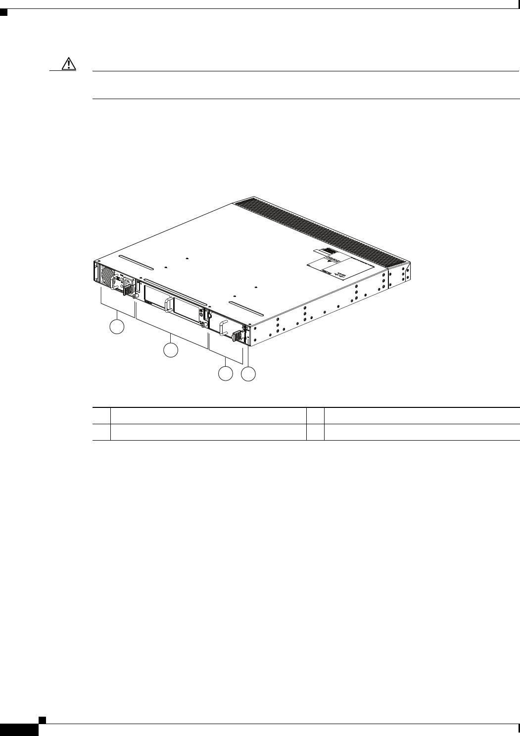
2-16
Cisco Nexus 2000 Series Hardware Installation Guide
Chapter 2 Using a Fabric Extender with a Cisco Nexus 7000 Series Switch
Cisco Nexus 2232TM FEX
Caution Make sure that all of the fan tray and power supply modules use the same airflow direction and have the
same color designation on the front. Otherwise, the switch can over heat and shut down,
The front of the Cisco Nexus 2232TM FEX chassis has one or two power supplies, a fan tray, and two
LEDs as shown in Figure 2-16. This FEX model requires one power supply, but if you want power
redundancy, you must install a second power supply.
Figure 2-16 Front View of the Cisco Nexus 2232TM Chassis
The rear of the Cisco Nexus 2232TM FEX has 32 1- and 10-Gigabit Ethernet downlink ports, eight
10-Gigabit Ethernet uplink ports, an HDMI port, and two LEDs, as shown in Figure 2-22.
2
1
34
239279
1Power supply 3Power supply (blank shown)
2Fan tray 4Status (top) and ID (bottom) LEDs
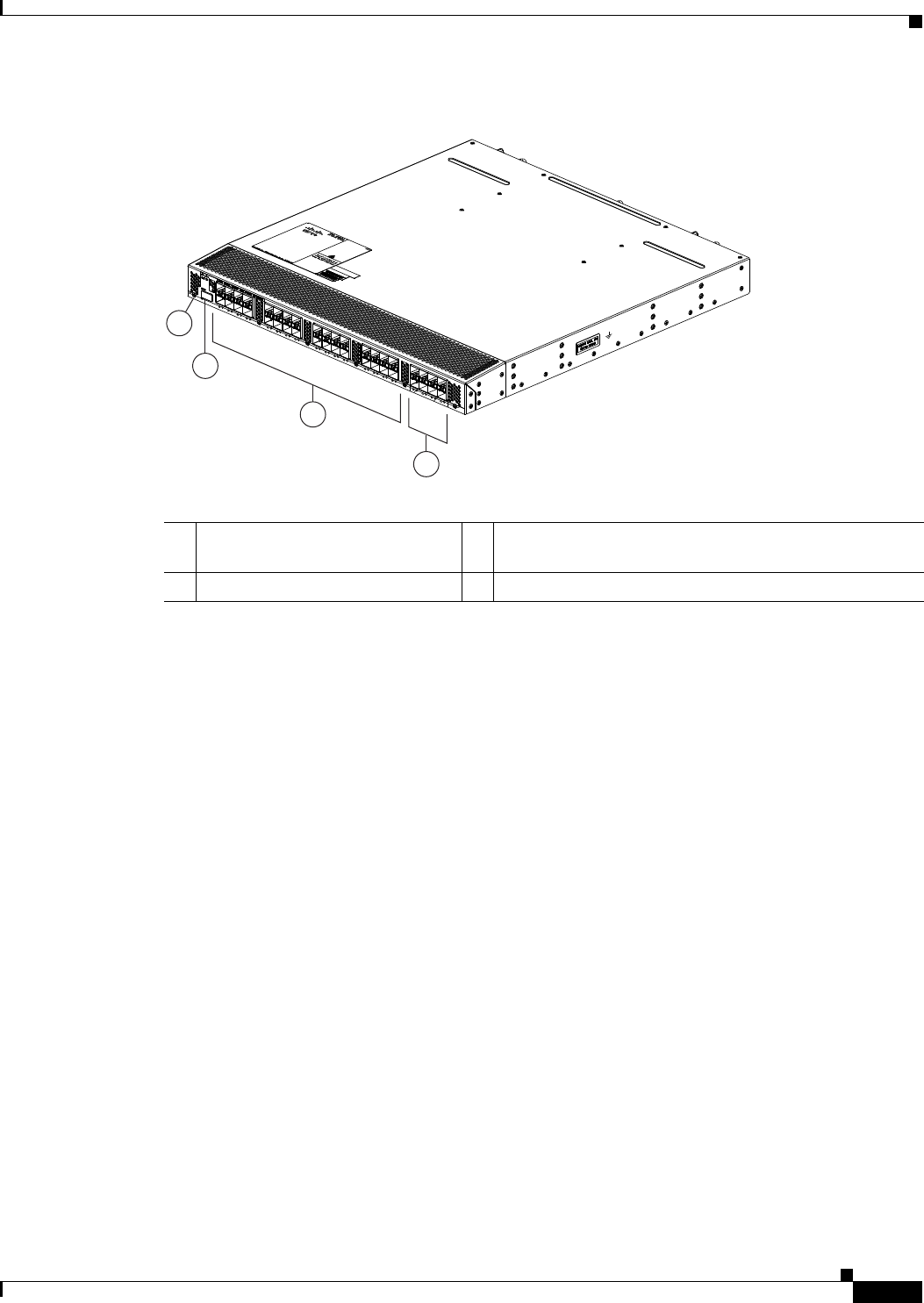
2-17
Cisco Nexus 2000 Series Hardware Installation Guide
Chapter 2 Using a Fabric Extender with a Cisco Nexus 7000 Series Switch
Cisco Nexus 2232TM FEX
Figure 2-17 Rear View of the Cisco Nexus 2232TM Chassis
For LED descriptions, see Appendix E, “LEDs.”
This section includes the following topics:
•Ports for the Cisco Nexus 2232TM FEX, page 2-17
•Power Supplies for the Cisco Nexus 2232TM FEX, page 2-18
•Fan Tray for the Cisco Nexus 2232TM FEX, page 2-19
•Transceivers and Connectors Supported by the Cisco Nexus 2232TM FEX, page 2-20
Ports for the Cisco Nexus 2232TM FEX
The downlink and uplink ports are numbered from top to bottom and then from left to right as shown in
Figure 2-23.
3
2
4
239278
1
1Status (top) and ID (bottom) LEDs 31- and 10-Gigabit host-facing Ethernet (downlink) ports
(48)
2HDMI port 410-Gigabit network-facing Ethernet (uplink) ports (8)
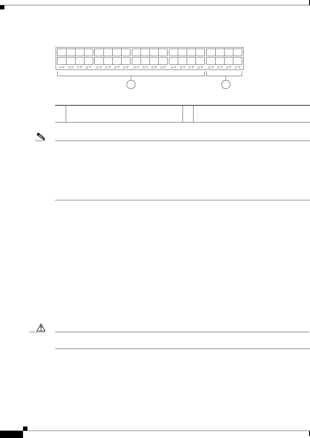
2-18
Cisco Nexus 2000 Series Hardware Installation Guide
Chapter 2 Using a Fabric Extender with a Cisco Nexus 7000 Series Switch
Cisco Nexus 2232TM FEX
Figure 2-18 Port Numbering on the Cisco Nexus 2232TM FEX
Note For a fully dedicated 10-Gbps bandwidth through a M1 Series 32-port 10-Gigabit Ethernet I/O module
(either the N7K-M132XP-12 or N7K-M132XP-12L), connect each FEX to one port in a set of four
shared ports on the module (you connect each set of shared ports to one FEX). If you are using the M2
Series 24-port, 10-Gigabit Ethernet I/O module (N7K-M224XP-23L), you can connect the FEX to any
of its ports for a fully dedicated bandwidth. If you are using the F2 Series 48-port, 10-Gigabit Ethernet
I/O module (N7K-F248XP-25), use the connectivity rule order (connect the same port numbers for each
port group (for example, if you connect ports 1 and 2 of a port-group, then connect the same ports of
another port group).
For information about the transceivers and connectors that you can use with these ports, see the
“Transceivers and Connectors Supported by the Cisco Nexus 2232TM FEX” section on page 2-20.
Power Supplies for the Cisco Nexus 2232TM FEX
The Cisco Nexus 2200 Platform FEX chassis have two slots for front-end AC or DC power supplies that
have port-side exhaust or port-side intake airflow. These chassis are fully functional with one power
supply, but you can install a second power supply for power redundancy. You can install any of the
following power supplies in those two bays:
•AC power supply with port-side exhaust airflow (N2200-PAC-400W)
•AC power supply with port-side intake airflow (N2200-PAC-400W-B)
•DC power supply with port-side exhaust airflow (N2200-PDC-400W)
•DC power supply with port-side intake airflow (N2200-PDC-350W-B)
Caution Make sure that all of the fan tray and power supply modules use the same airflow direction and have the
same color designation on the front. Otherwise, the switch can over heat and shut down,
If you have only one power supply in a chassis, then you must install a blank filler plate
(N2200-P-BLNK) in the open slot to maintain the designed airflow.
For more information on these power supplies, see the “Power Supplies for the Cisco Nexus 2248TP-E
FEX” section on page 2-4 and the power supply specifications in the Appendix B, “Technical
Specifications”.
12
330042
1
2
3
4
5
6
7
8
1
2
3
4
5
6
7
8
911
14
13 15
12
10 16
17
18
19
20
21 23
22
24
25
26
27
28
29 31
30 32
11- and 10-Gigabit Ethernet downlink ports,
numbered 1 through 32
210-Gigabit Ethernet uplink ports, numbered 1
through 8
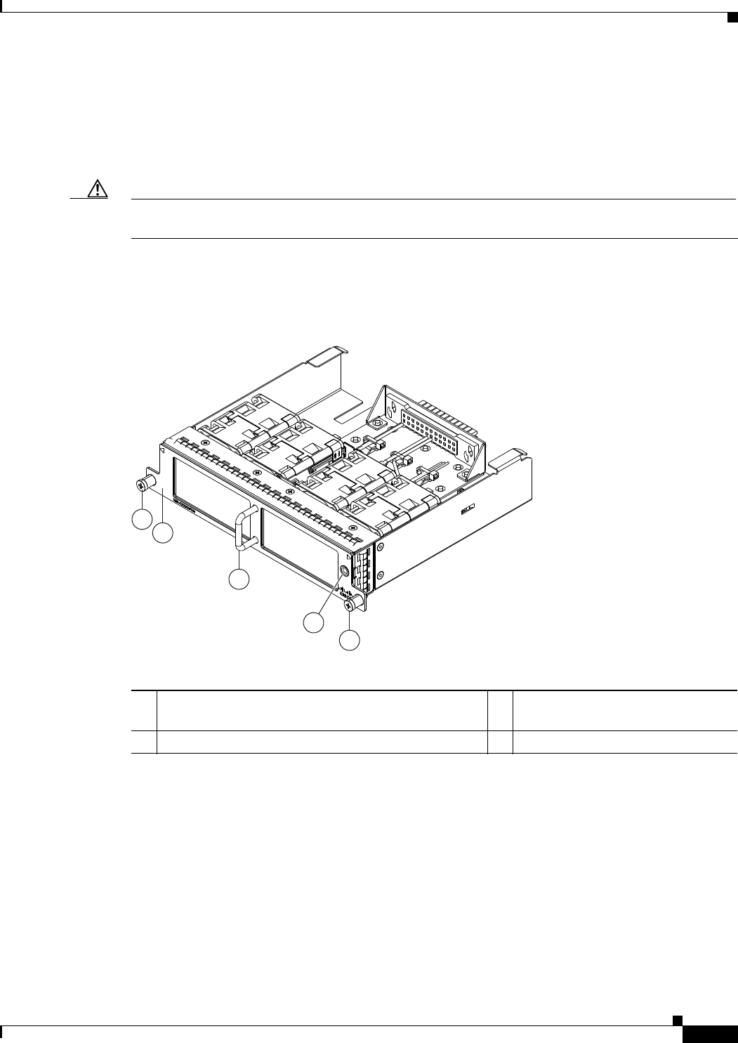
2-19
Cisco Nexus 2000 Series Hardware Installation Guide
Chapter 2 Using a Fabric Extender with a Cisco Nexus 7000 Series Switch
Cisco Nexus 2232TM FEX
Fan Tray for the Cisco Nexus 2232TM FEX
The Cisco Nexus 2232PP and 2232TM FEX use the same fan tray, which you can order with either
port-side exhaust airflow (N2K-C2248-FAN) or port-side intake airflow (N2K-C2248-FAN-B). The fan
tray includes a status LED that indicates whether the module is operational.
Caution Make sure that all of the fan tray and power supply modules use the same airflow direction and have the
same color designation on the front. Otherwise, the switch can over heat and shut down,
Figure 2-19 shows the fan tray with port-side exhaust airflow (no black stripe across the front), and
Figure 2-20 shows the fan tray with port-side intake airflow (black stripe across the front).
Figure 2-19 Port-Side Exhaust Airflow Fan Tray for the Cisco Nexus 2232PP and 2232TM FEXs
4
2
1
3
1
239292
1Captive screws (2) 3Port-side exhaust airflow indicated
by a lack of black stripe on the front.
2Handle used for removing and installing the module 4Status LED
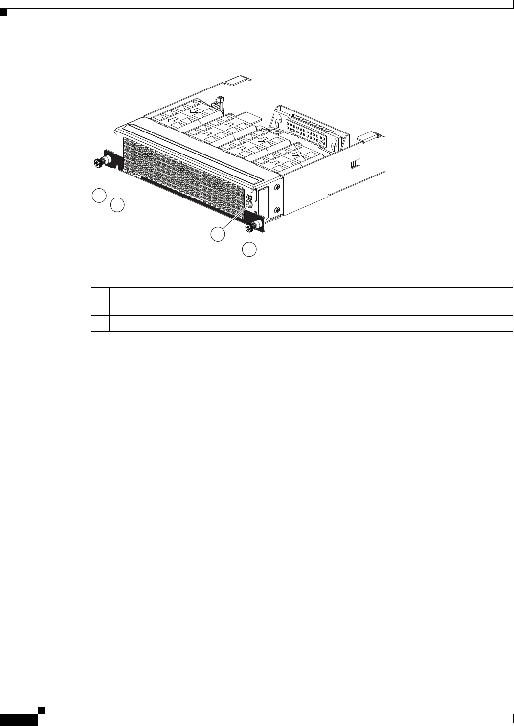
2-20
Cisco Nexus 2000 Series Hardware Installation Guide
Chapter 2 Using a Fabric Extender with a Cisco Nexus 7000 Series Switch
Cisco Nexus 2232TM FEX
Figure 2-20 Port-Side Intake Airflow Fan Tray for the Cisco Nexus 2232PP and 2232TM FEXs
For more information on this fan tray, see the fan tray specifications in Appendix B, “Technical
Specifications”. For LED descriptions, see Appendix E, “LEDs”.
Transceivers and Connectors Supported by the Cisco Nexus 2232TM FEX
The Cisco Nexus 2232TM FEX supports SFP+ Ethernet optical and copper transceivers and optical FEX
Transceivers (FETs) for up to eight fabric uplink connections to the following Cisco Nexus 7000 Series
switch I/O modules:
•F2 Series 48-port 10-Gigabit I/O module (N7K-F248XP-25)
•M1 Series 32-port, 10-Gigabit Ethernet I/O module (N7K-M132XP-12)
•M1 Series 32-port, 10-Gigabit Ethernet I/O module with XL option (N7K-M132XP-12L)
•M2 Series 24-port 10-Gigabit I/O module (N7K-M224XP-23L)
You must use the same transceivers on both ends of the same uplink cable.
239936
2
1
3
1
1Captive screws (2) 3Port-side intake airflow indicated by
a black stripe on the front.
2Handle used for removing and installing the module 4Status LED

2-21
Cisco Nexus 2000 Series Hardware Installation Guide
Chapter 2 Using a Fabric Extender with a Cisco Nexus 7000 Series Switch
Cisco Nexus 2232TM FEX
Note To get the fully dedicated 10-Gbps bandwidth through a M1 Series 32-port 10-Gigabit Ethernet I/O
module, connect each FEX to one port in a set of four shared ports on the module (you connect each set
of shared ports to one FEX) and use the shared mode on the I/O module. If you are using the F2 Series
48-port 10-Gigabit Ethernet I/O module (N7K-F248XP-25) or the M2 Series 24-port 10-Gigabit
Ethernet I/O module (N7K-M224XP-23L), you can connect the FEX to any of its ports.
The Cisco Nexus 2232TM FEX also supports RJ-45 connectors for up to 32 downlink connections to
hosts. Table 2-2 lists the transceivers supported by this FEX for its uplink and downlink connections.
Figure 2-10 on page 2-10 shows the major features of the SFP+ optical transceiver used for uplink
connections.
Figure 2-11 on page 2-11 shows the major features of the SFP+ copper transceiver and cable used for
uplink connections.
Figure 2-12 on page 2-11 shows the major features of RJ-45 connectors, which are used for the downlink
connections.
Table 2-6 Supported Transceivers and Connector for the Cisco Nexus 2232TM FEX Uplink Interfaces
Transceiver or
Connector
Cable
Type
Fabric
Interface
(Uplink)
Host
Interface
(Downlink) Comments
FET-10G Optical X – 10 Gbps FEX transceiver
SFP-10G-LR Optical X – 10 Gbps long range transceiver (up to 6.2 miles [10 km])
SFP-10G-SR Optical X – 10 Gbps Short range transceiver (up to 984 feet [300 m])
SFP -H10GB-CU1M1Copper X – 10 Gbps Twinax, passive transceiver (3.3 feet [1 meter])
SFP -H10GB-CU3M Copper X – 10 Gbps Twinax, passive transceiver (9.8 feet [3 meters)
SFP -H10GB-CU5M Copper X – 10 Gbps Twinax, passive transceiver (16.4 feet [5 meters])
SFP -H10GB-ACU7M Copper X – 10 Gbps Twinax, active transceiver (23.0 feet [7 meters])
SFP -H10GB-ACU10M Copper X – 10 Gbps Twinax, active transceiver (32.8 feet [10 meters])
RJ-45 Copper – X 100/1000 Mbps Connector
1. The SFP-H10GB-CUxM transceivers are not supported by the M1 Series 32-port 10-Gigabit Ethernet I/O module (N7K-M132XP-12). These transceivers
are supported by the other Cisco Nexus 7000 Series I/O modules.

2-22
Cisco Nexus 2000 Series Hardware Installation Guide
Chapter 2 Using a Fabric Extender with a Cisco Nexus 7000 Series Switch
Cisco Nexus 2232PP FEX
Cisco Nexus 2232PP FEX
The Cisco Nexus 2232PP FEX is a stackable 1- and 10-Gigabit FEX that has 32 1- and 10-Gbps Ethernet
host-facing (downlink) SFP or SFP+ ports and eight 10-Gbps Ethernet and Fibre Channel over Ethernet
(FCoE) network-facing (uplink) SFP+ or FET ports. It requires a 19-inch (48.26 cm) rack for its
installation. Table 2-7 lists its physical characteristics.
You can order the Cisco Nexus 2232PP with port-side exhaust or port-side intake airflow and with AC
or DC power supplies. If you are going to install the port side in a hot aisle, then order port-side exhaust
airflow for all of the fan trays and power supplies. If you are going to install the port side in the cold
aisle, order port-side intake airflow for all of the fan trays and power supplies.
Caution Make sure that all of the fan tray and power supply modules use the same airflow direction and have the
same color designation on the front. Otherwise, the switch can over heat and shut down,
The front of the Cisco Nexus 2232PP FEX chassis has one or two power supplies, a fan tray, and two
LEDs as shown in Figure 2-21. This FEX model requires one power supply, but if you want power
redundancy, you must install a second power supply.
Table 2-7 Physical Characteristics for the Cisco Nexus 2232PP FEX
Dimensions
Width
Depth
Height
17.3 inches (43.94 cm)
17.7 inches (44.96 cm)
1.72 inches (4.37 cm)
Weight118.3 lb (8.3 kg)
1. Measured with two power supplies and one fan module installed
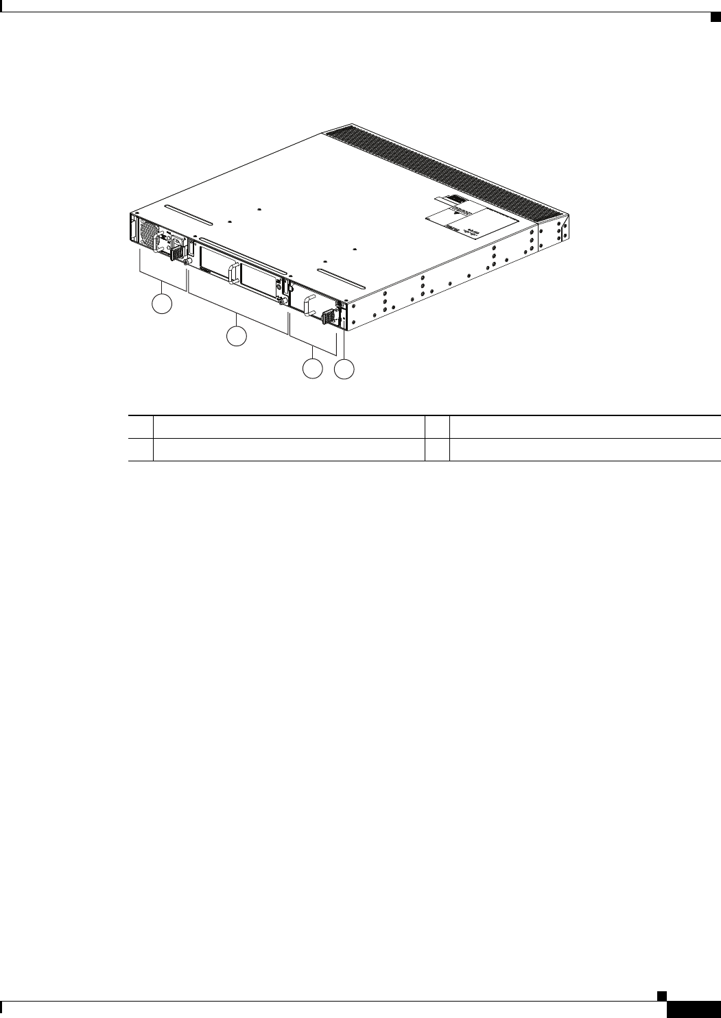
2-23
Cisco Nexus 2000 Series Hardware Installation Guide
Chapter 2 Using a Fabric Extender with a Cisco Nexus 7000 Series Switch
Cisco Nexus 2232PP FEX
Figure 2-21 Front View of the Cisco Nexus 2232PP Chassis
The rear of the Cisco Nexus 2232PP FEX has 32 1- and 10-Gigabit Ethernet downlink SFP or SFP+
ports, eight 10-Gigabit Ethernet uplink SFP+ or FET ports, an HDMI port, and two LEDs, as shown in
Figure 2-22.
2
1
34
239279
1Power supply 3Power supply (blank shown)
2Fan tray 4Status (top) and ID (bottom) LEDs
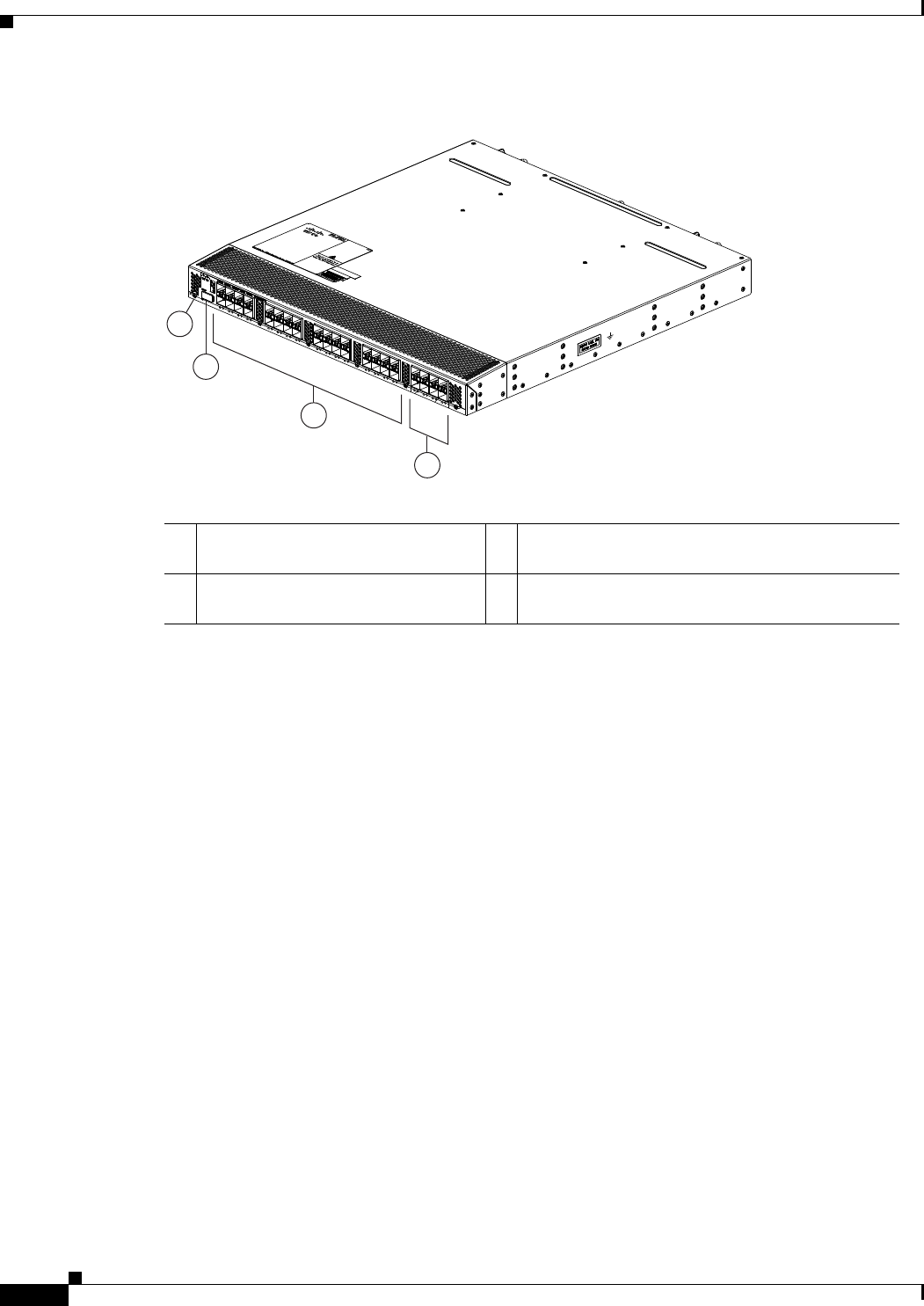
2-24
Cisco Nexus 2000 Series Hardware Installation Guide
Chapter 2 Using a Fabric Extender with a Cisco Nexus 7000 Series Switch
Cisco Nexus 2232PP FEX
Figure 2-22 Rear View of the Cisco Nexus 2232PP Chassis
For LED descriptions, see Appendix E, “LEDs.”
This section includes the following topics:
•Ports for the Cisco Nexus 2232PP FEX, page 2-24
•Power Supplies for the Cisco Nexus 2232PP FEX, page 2-25
•Fan Tray for the Cisco Nexus 2232PP FEX, page 2-26
•Transceivers Supported by the Cisco Nexus 2232PP FEX, page 2-26
Ports for the Cisco Nexus 2232PP FEX
The downlink and uplink ports are numbered from top to bottom and then from left to right as shown in
Figure 2-23.
3
2
4
239278
1
1Status (top) and ID (bottom) LEDs 31- and 10-Gigabit host-facing Ethernet (downlink)
SFP or SFP+ ports (48)
2HDMI port 410-Gigabit network-facing Ethernet (uplink) SFP+
ports (4)
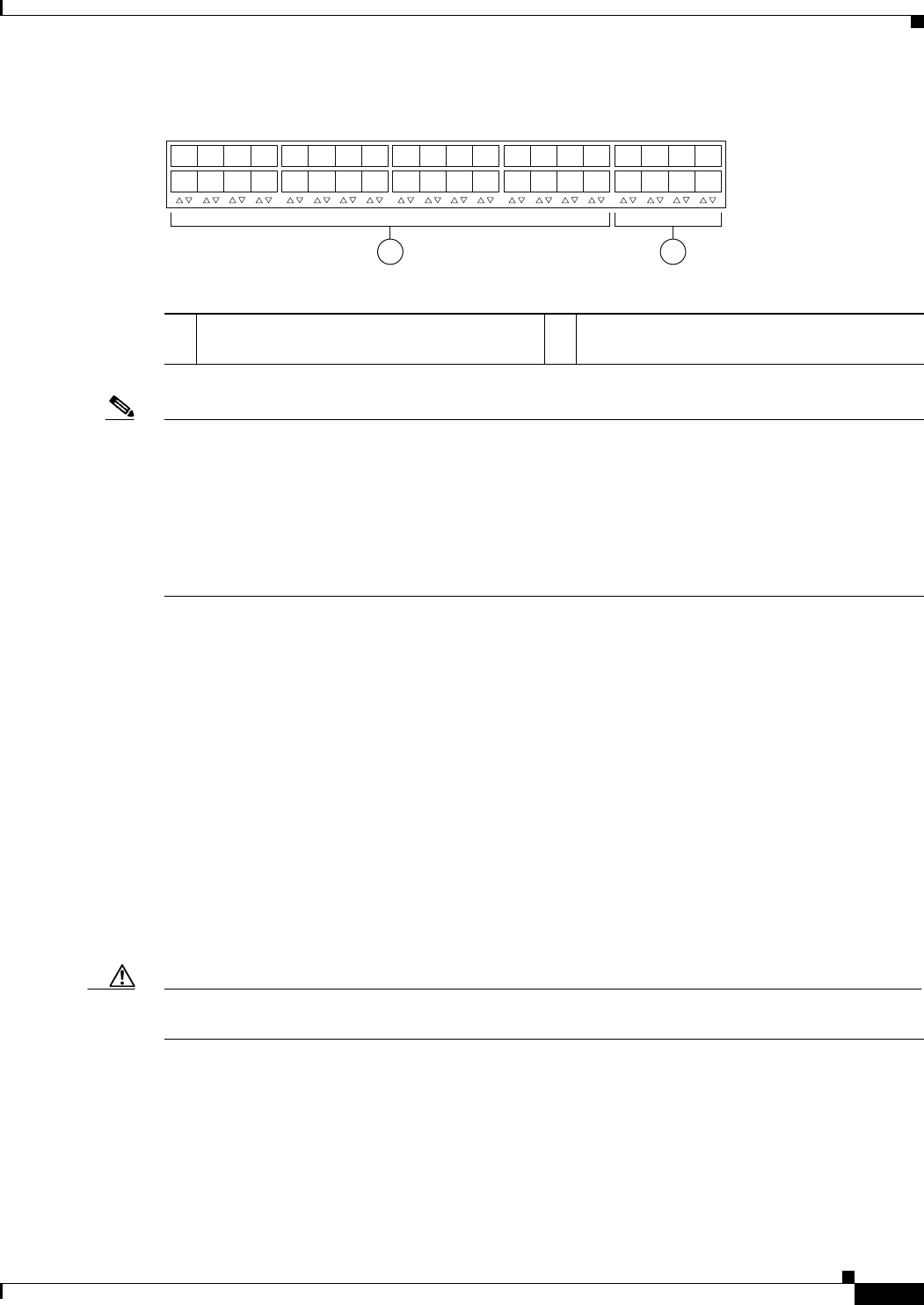
2-25
Cisco Nexus 2000 Series Hardware Installation Guide
Chapter 2 Using a Fabric Extender with a Cisco Nexus 7000 Series Switch
Cisco Nexus 2232PP FEX
Figure 2-23 Port Numbering on the Cisco Nexus 2232PP FEX
Note For a fully dedicated 10-Gbps bandwidth through a M1 Series 32-port 10-Gigabit Ethernet I/O module
(either the N7K-M132XP-12 or N7K-M132XP-12L), connect each FEX to one port in a set of four
shared ports on the module (you connect each set of shared ports to one FEX). If you are using the M2
Series 24-port, 10-Gigabit Ethernet I/O module (N7K-M224XP-23L), you can connect the FEX to any
of its ports for a fully dedicated bandwidth. If you are using the F2 Series 48-port, 10-Gigabit Ethernet
I/O module (N7K-F248XP-25), use the connectivity rule order (connect the same port numbers for each
port group (for example, if you connect ports 1 and 2 of a port-group, then connect the same ports of
another port group).
For information about the transceivers and connectors that you can use with these ports, see the
“Transceivers Supported by the Cisco Nexus 2232PP FEX” section on page 2-26.
Power Supplies for the Cisco Nexus 2232PP FEX
The Cisco Nexus 2200 Platform FEX chassis have two slots for front-end AC or DC power supplies that
have port-side exhaust or port-side intake airflow. These chassis are fully functional with one power
supply, but you can install a second power supply for power redundancy. You can install any of the
following power supplies in those two bays:
•AC power supply with port-side exhaust airflow (N2200-PAC-400W)
•AC power supply with port-side intake airflow (N2200-PAC-400W-B)
•DC power supply with port-side exhaust airflow (N2200-PDC-400W)
•DC power supply with port-side intake airflow (N2200-PDC-350W-B)
Caution Make sure that all of the fan tray and power supply modules use the same airflow direction and have the
same color designation on the front. Otherwise, the switch can over heat and shut down,
For information on these power supplies, see the “Power Supplies for the Cisco Nexus 2248TP FEX”
section on page 2-14 and the power supply specifications in the “Technical Specifications” section on
page B-1.
12
330042
1
2
3
4
5
6
7
8
1
2
3
4
5
6
7
8
911
14
13 15
12
10 16
17
18
19
20
21 23
22
24
25
26
27
28
29 31
30 32
11- and 10-Gigabit Ethernet downlink ports,
numbered 1 through 32
210-Gigabit Ethernet uplink ports, numbered 1
through 8

2-26
Cisco Nexus 2000 Series Hardware Installation Guide
Chapter 2 Using a Fabric Extender with a Cisco Nexus 7000 Series Switch
Cisco Nexus 2232PP FEX
Fan Tray for the Cisco Nexus 2232PP FEX
The Cisco Nexus 2232PP and 2232TM FEX use the same fan tray, which you can order with either
port-side exhaust airflow (N2K-C2232-FAN) or port-side intake airflow (N2K-C2232-FAN-B).
Caution Make sure that all of the fan tray and power supply modules use the same airflow direction and have the
same color designation on the front. Otherwise, the switch can over heat and shut down,
For more information on this fan tray, see the “Fan Tray for the Cisco Nexus 2232TM FEX” section on
page 2-19 and the fan tray specifications in Appendix B, “Technical Specifications”. For LED
descriptions, see Appendix E, “LEDs”.
Transceivers Supported by the Cisco Nexus 2232PP FEX
The Cisco Nexus 2232PP FEX supports SFP+ Ethernet optical and copper transceivers and optical FEX
Transceivers (FETs) for up to eight fabric uplink connections to the following Cisco Nexus 7000 Series
switch I/O modules:
•F2 Series 48-port 10-Gigabit I/O module (N7K-F248XP-25)
•M1 Series 32-port 10-Gigabit Ethernet I/O module (N7K-M132XP-12)
•M1 Series 32-port 10-Gigabit Ethernet I/O module with XL option (N7K-M132XP-12L)
•M2 Series 24-port 10-Gigabit I/O module (N7K-M224XP-23L)
You must use the same transceivers on both ends of the same uplink cable.
Note To get the fully dedicated 10-Gbps bandwidth through a M1 Series 32-port 10-Gigabit Ethernet I/O
module, connect each FEX to one port in a set of four shared ports on the module (you connect each set
of shared ports to one FEX) and use the shared mode on the I/O module. If you are using the F2 Series
48-port 10-Gigabit Ethernet I/O module (N7K-F248XP-25) or the M2 Series 24-port 10-Gigabit
Ethernet I/O module (N7K-M224XP-23L), you can connect the FEX to any of its ports.
The Cisco Nexus 2232TM FEX also supports RJ-45 connectors for up to 32 downlink connections to
hosts. Table 2-2 lists the transceivers supported by this FEX for its uplink and downlink connections.
Table 2-8 Supported Transceivers and Connector for the Cisco Nexus 2232TM FEX Uplink Interfaces
Transceiver or
Connector
Cable
Type
Fabric
Interface
(Uplink)
Host
Interface
(Downlink) Comments
FET-10G Optical X – 10 Gigabit FEX transceiver
GLC-LH-SM Optical – X Gigabit SFP transceiver
GLC-SX-MM Optical – X Gigabit SFP transceiver
GLC-T Copper – X Gigabit SFP transceiver
SFP-10G-LR Optical X X 10 Gigabit long range transceiver (up to 6.2 miles [10 km])
SFP-10G-SR Optical X X 10 Gigabit Short range transceiver (up to 984 feet [300 m])
2-27
Cisco Nexus 2000 Series Hardware Installation Guide
Chapter 2 Using a Fabric Extender with a Cisco Nexus 7000 Series Switch
Cisco Nexus 2224TP FEX
Figure 2-10 on page 2-10 shows the major features of the SFP+ optical transceiver used for uplink
connections.
Figure 2-11 on page 2-11 shows the major features of the SFP+ copper transceiver and cable used for
uplink connections.
Figure 2-12 on page 2-11 shows the major features of RJ-45 connectors, which are used for the downlink
connections.
Cisco Nexus 2224TP FEX
The Cisco Nexus 2224TP FEX is a stackable Gigabit Ethernet FEX that has 24 100/1000BASE-T
Ethernet host-facing (downlink) RJ-45 ports and two 10-Gigabit Ethernet network-facing (uplink) SFP+
ports. It requires a 19-inch (48.26 cm) rack for its installation. Table 2-9 lists its physical characteristics.
You can order the Cisco Nexus 2224TP FEX with port-side exhaust or port-side intake airflow and with
AC or DC power supplies. If you are going to install the port side in a hot aisle, then order port-side
exhaust airflow for all of the fan trays and power supplies. If you are going to install the port side in the
cold aisle, order port-side intake airflow for all of the fan trays and power supplies.
SFP-GE-L Optical – X Gigabit SFP transceiver
SFP-GE-S Optical – X Gigabit SFP transceiver
SFP-GE-T Copper – X Gigabit SFP transceiver
SFP -H10GB-CU1M1Copper X X 10 Gigabit Twinax, passive transceiver (3.3 feet [1 meter])
SFP -H10GB-CU3M1Copper X X 10 Gigabit Twinax, passive transceiver (9.8 feet [3 meters)
SFP -H10GB-CU5M1Copper X X 10 Gigabit Twinax, passive transceiver (16.4 feet [5 meters])
SFP -H10GB-ACU7M Copper X X 10 Gigabit Twinax, active transceiver (23.0 feet [7 meters])
SFP -H10GB-ACU10M Copper X X 10 Gigabit Twinax, active transceiver (32.8 feet [10 meters])
1. The SFP-H10GB-CUxM transceivers are not supported by the M1 Series 32-port 10-Gigabit Ethernet I/O module (N7K-M132XP-12). These transceivers
are supported by the other Cisco Nexus 7000 Series I/O modules.
Table 2-8 Supported Transceivers and Connector for the Cisco Nexus 2232TM FEX Uplink Interfaces
Transceiver or
Connector
Cable
Type
Fabric
Interface
(Uplink)
Host
Interface
(Downlink) Comments
Table 2-9 Physical Characteristics for the Cisco Nexus 2224TP FEX
Dimensions
Width
Depth
Height
17.3 inches (43.94 cm)
17.7 inches (44.96 cm)
1.72 inches (4.37 cm)
Weight116.6 lb (7.53 kg)
1. Measured with two power supplies and one fan module installed.
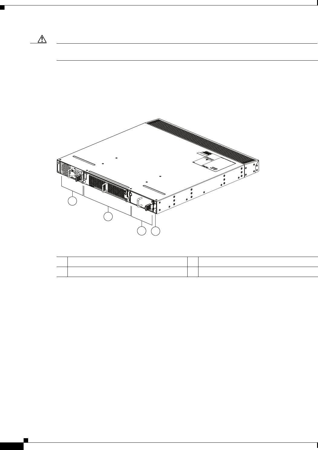
2-28
Cisco Nexus 2000 Series Hardware Installation Guide
Chapter 2 Using a Fabric Extender with a Cisco Nexus 7000 Series Switch
Cisco Nexus 2224TP FEX
Caution Make sure that all of the fan tray and power supply modules use the same airflow direction and have the
same color designation on the front. Otherwise, the switch can over heat and shut down,
The front of the Cisco Nexus 2224TP FEX chassis has one or two power supplies, a fan tray, and two
LEDs as shown in Figure 2-24. This FEX model requires one power supply, but if you want power
redundancy, you must install a second power supply.
Figure 2-24 Front View of the Cisco Nexus 2224TP Chassis
The rear of the Cisco Nexus 2224TP FEX has 24 100/1000 BASE-T Ethernet downlink ports, two
10-Gigabit Ethernet uplink ports, an HDMI port, and LEDs, as shown in Figure 2-25.
2
1
34
239281
1Power supply 3Power supply (blank shown)
2Fan tray 4Status (top) and ID (bottom) LEDs
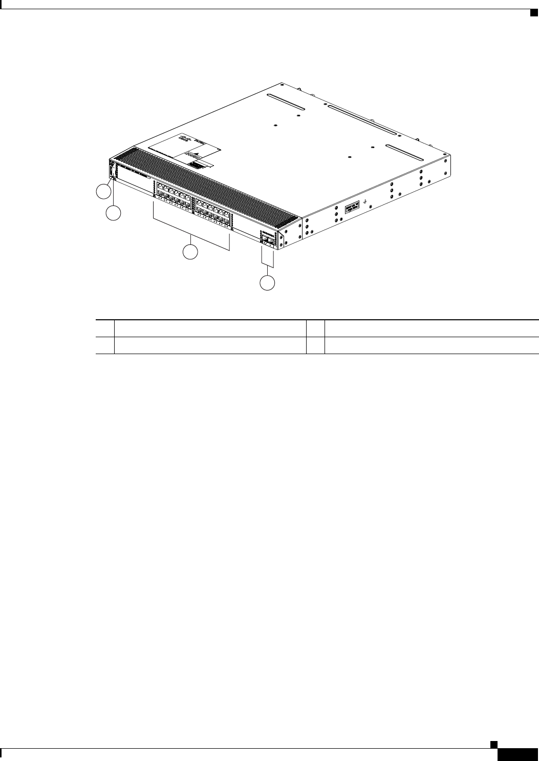
2-29
Cisco Nexus 2000 Series Hardware Installation Guide
Chapter 2 Using a Fabric Extender with a Cisco Nexus 7000 Series Switch
Cisco Nexus 2224TP FEX
Figure 2-25 Rear View of the Cisco Nexus 2224TP Chassis
For LED descriptions, see Appendix E, “LEDs.”
This section includes the following topics:
•Ports for the Cisco Nexus 2224TP FEX, page 2-29
•Power Supplies for the Cisco Nexus 2224TP FEX, page 2-30
•Fan Tray for the Cisco Nexus 2224TP FEX, page 2-31
•Transceivers and Connectors Supported by the Cisco Nexus 2224TP FEX, page 2-31
Ports for the Cisco Nexus 2224TP FEX
The downlink and uplink ports are numbered from top to bottom and then from left to right as shown in
Figure 2-26.
3
4
239280
2
1
1Status (top) and ID (bottom) LEDs 3100/1000 Ethernet downlink ports (24)
2HDMI port 410-Gigabit Ethernet uplink ports (2)
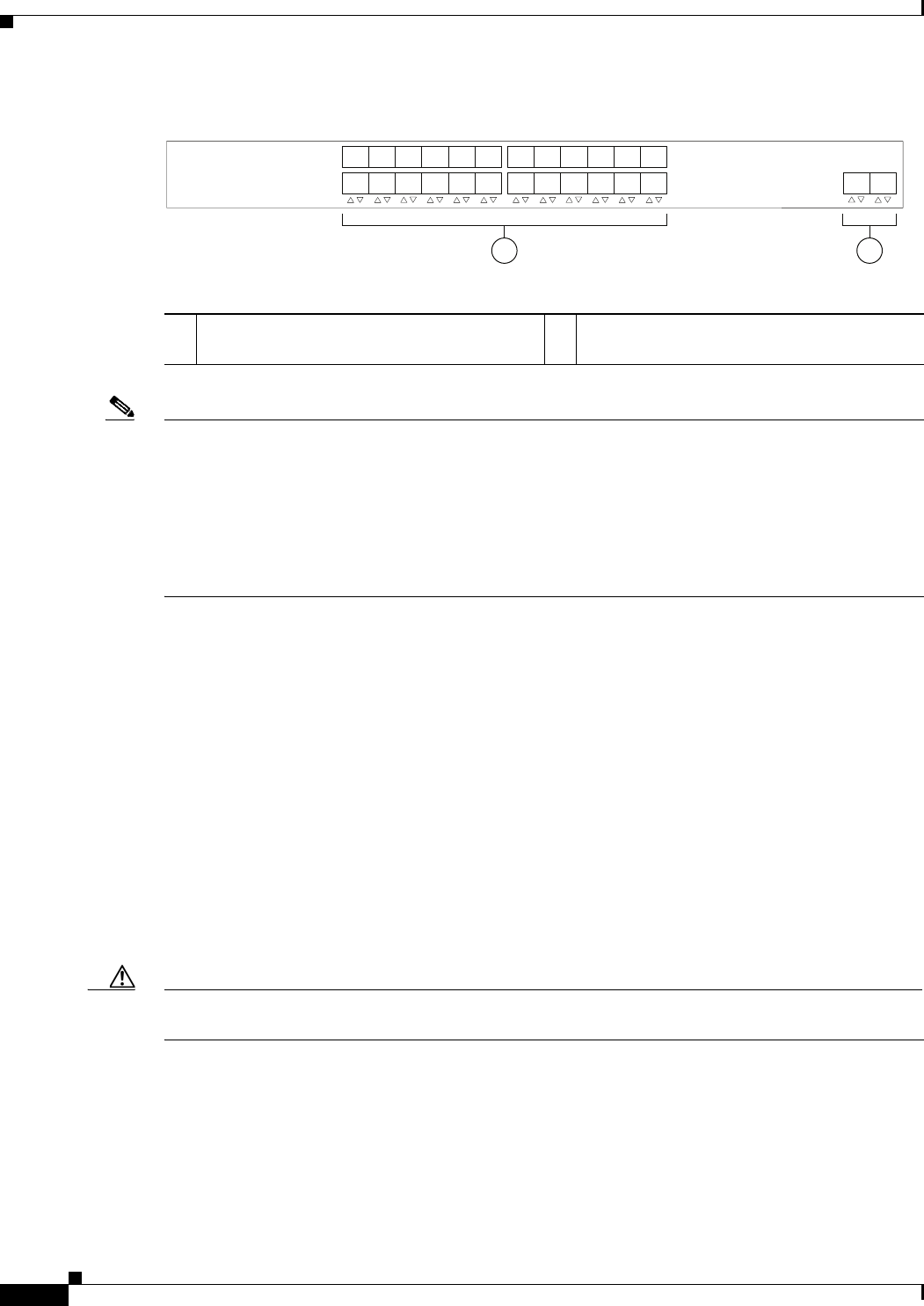
2-30
Cisco Nexus 2000 Series Hardware Installation Guide
Chapter 2 Using a Fabric Extender with a Cisco Nexus 7000 Series Switch
Cisco Nexus 2224TP FEX
Figure 2-26 Port Numbering on the Cisco Nexus 2224TP FEX
Note For a fully dedicated 10-Gbps bandwidth through a M1 Series 32-port 10-Gigabit Ethernet I/O module
(either the N7K-M132XP-12 or N7K-M132XP-12L), connect each FEX to one port in a set of four
shared ports on the module (you connect each set of shared ports to one FEX). If you are using the M2
Series 24-port, 10-Gigabit Ethernet I/O module (N7K-M224XP-23L), you can connect the FEX to any
of its ports for a fully dedicated bandwidth. If you are using the F2 Series 48-port, 10-Gigabit Ethernet
I/O module (N7K-F248XP-25), use the connectivity rule order (connect the same port numbers for each
port group (for example, if you connect ports 1 and 2 of a port-group, then connect the same ports of
another port group).
For information about the transceivers and connectors that you can use with these ports, see the
“Transceivers and Connectors Supported by the Cisco Nexus 2224TP FEX” section on page 2-31.
Power Supplies for the Cisco Nexus 2224TP FEX
The Cisco Nexus 2200 Platform FEX chassis have two slots for front-end AC or DC power supplies that
have port-side exhaust or port-side intake airflow. These chassis are fully functional with one power
supply, but you can install a second power supply for power redundancy. You can install any of the
following power supplies in those two bays:
•AC power supply with port-side exhaust airflow (N2200-PAC-400W)
•AC power supply with port-side intake airflow (N2200-PAC-400W-B)
•DC power supply with port-side exhaust airflow (N2200-PDC-400W)
•DC power supply with port-side intake airflow (N2200-PDC-350W-B)
Caution Make sure that all of the fan tray and power supply modules use the same airflow and have the same
color designation on the front. Otherwise, the switch can over heat and shut down,
For information on these power supplies, see the “Power Supplies for the Cisco Nexus 2248TP FEX”
section on page 2-14 and the power supply specifications in Appendix B, “Technical Specifications”.
1 2
330046
1
2
3
4
5
6
7
8
9
10
11
12
13
14
15
16
17
18
19
20
21
22
23
24 12
11- and 10-Gigabit Ethernet downlink ports,
numbered 1 through 24
210-Gigabit Ethernet uplink ports, numbered 1
through 2
2-31
Cisco Nexus 2000 Series Hardware Installation Guide
Chapter 2 Using a Fabric Extender with a Cisco Nexus 7000 Series Switch
Cisco Nexus 2224TP FEX
Fan Tray for the Cisco Nexus 2224TP FEX
The Cisco Nexus 2224TP, 2248TP, and 2248TP-E FEXs use the same fan tray that you can order with
either port-side exhaust airflow (N2K-C2248-FAN) or port-side intake airflow (N2K-C2248-FAN-B).
Caution Make sure that all of the fan tray and power supply modules use the same airflow and have the same
color designation on the front. Otherwise, the switch can over heat and shut down,
For information on this fan tray, see the “Fan Tray for the Cisco Nexus 2248TP FEX” section on
page 2-14 and the fan tray specifications in Appendix B, “Technical Specifications”. For LED
descriptions, see Appendix E, “LEDs”.
Transceivers and Connectors Supported by the Cisco Nexus 2224TP FEX
The Cisco Nexus 2224TP FEX supports SFP+ Ethernet optical and copper transceivers and optical FEX
Transceivers (FETs) for up to four fabric uplink connections to Cisco Nexus 7000 Series switches, and
it supports RJ-45 connectors for up to 48 downlink connections to hosts. For each uplink cable, you must
use the same transceiver on both ends. Table 2-2 lists the transceivers supported by this FEX for its
uplink fabric.
Figure 2-10 on page 2-10 shows the SFP+ optical transceiver used for uplink connections.
Figure 2-11 on page 2-11 identifies the major features of the SFP+ copper transceiver and cable used for
uplink connections.
Figure 2-12 on page 2-11 identifies the major features of RJ-45 connectors, which are used for the
downlink connections.
Table 2-10 Supported Transceivers and Connector for the Cisco Nexus 2224TP FEX Uplink Interfaces
Transceiver or
Connector
Cable
Type
Fabric
Interface
(Uplink)
Host
Interface
(Downlink) Comments
FET-10G Optical X – 10 Gbps FEX transceiver
SFP-10G-LR Optical X – 10 Gbps long range transceiver (up to 6.2 miles [10 km])
SFP-10G-SR Optical X – 10 Gbps Short range transceiver (up to 984 feet [300 m])
SFP -H10GB-CU1M Copper X – 10 Gbps Twinax, passive transceiver (3.3 feet [1 meter])
SFP -H10GB-CU3M Copper X – 10 Gbps Twinax, passive transceiver (9.8 feet [3 meters)
SFP -H10GB-CU5M Copper X – 10 Gbps Twinax, passive transceiver (16.4 feet [5 meters])
SFP -H10GB-ACU7M Copper X – 10 Gbps Twinax, active transceiver (23.0 feet [7 meters])
SFP -H10GB-ACU10M Copper X – 10 Gbps Twinax, active transceiver (32.8 feet [10 meters])
RJ-45 Copper – X 100/1000 Mbps Connector

2-32
Cisco Nexus 2000 Series Hardware Installation Guide
Chapter 2 Using a Fabric Extender with a Cisco Nexus 7000 Series Switch
Cisco Nexus 2224TP FEX

CHAPTER
3-1
Cisco Nexus 2000 Series Hardware Installation Guide
3
Using a Fabric Extender with a Cisco Nexus 9000
Series Switch
This chapter describes the Cisco Nexus 2200 Platform Fabric Extender (FEX) chassis and the
components that you can connect to a Cisco Nexus 9000 Series switch.
This chapter includes the following sections:
•Information About Using a Fabric Extender with a Cisco Nexus 9396PX Switch, page 3-1
•Cisco Nexus 2248TP-E FEX, page 3-1
•Cisco Nexus 2248TP FEX, page 3-10
•Cisco Nexus 2232TM FEX, page 3-15
•Cisco Nexus 2232PP FEX, page 3-21
•Cisco Nexus 2224TP FEX, page 3-25
Information About Using a Fabric Extender with a Cisco Nexus
9396PX Switch
With Cisco NX-OS Release 6.1(2)I2(3) and later releases, you can extend the Cisco Nexus 9396PX
switch architecture by connecting up to six FEXs as remote I/O modules. Depending on which FEX
model that you connect to the switch, the FEX provides top-of-the-rack connectivity for up to 48, 32, or
24 hosts, and it becomes an extension of the parent Cisco Nexus 9396PX switch fabric, with the FEX
and the switch becoming a virtual modular system. The FEX forwards all 100/1000 Ethernet or 1- and
10-Gigabit Ethernet traffic from the hosts to the switch over 10-Gbps uplinks. Traffic flows from the
switch to the FEX over the 10-Gbps uplinks and to the individual hosts over 100/1000 Ethernet or 1- and
10-Gigabit Ethernet downlinks.
Cisco Nexus 2248TP-E FEX
The Cisco Nexus 2248TP-E FEX (N2K-C2248TP-E) is a stackable 1-RU FEX that has 48 100/1000
Ethernet host interfaces (downlink ports for copper RJ-45 connectors) and four 10-Gigabit Ethernet
fabric interfaces (uplink ports for copper/optical SFP+ connectors). This FEX requires a 19-inch
(48.26-cm) rack for its installation. Table 3-1 lists its physical characteristics.
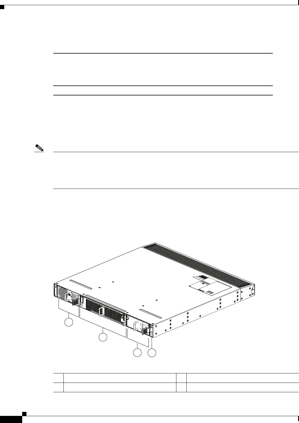
3-2
Cisco Nexus 2000 Series Hardware Installation Guide
Chapter 3 Using a Fabric Extender with a Cisco Nexus 9000 Series Switch
Cisco Nexus 2248TP-E FEX
You can order the Cisco Nexus 2248TP-E FEX with port-side exhaust or port-side intake airflow and
with AC or DC power supplies. If you are going to install the port side in a hot aisle, then order
port-side-exhaust airflow for all of the fan trays and power supplies. If you are going to install the port
side in the cold aisle, order port-side-intake airflow for all of the fan trays and power supplies.
Note For visual identification, port-side-intake airflow power supplies and fan trays have a black stripe across
their front, and port-side-exhaust airflow modules do not have a black stripe across their front. All of the
power supplies and fan trays must have the same direction of airflow for the components to properly
function (all of these components must either have a black stripe or all of the components must not have
a black stripe).
The front of the Cisco Nexus 2248TP-E FEX chassis has one or two power supplies, a fan tray, and two
chassis LEDs as shown in Figure 3-1. This FEX model requires one power supply, but if you want power
redundancy, you must install a second power supply.
Figure 3-1 Front View of the Cisco Nexus 2248TP-E Chassis
Table 3-1 Physical Characteristics for the Cisco Nexus 2248TP-E FEX
Dimensions
Width
Depth
Height
17.3 inches (43.9 cm)
20.0 inches (50.8 cm)
1.72 inches (4.4 cm)
Weight117.7 lb (8.0 kg)
1. Measured with two power supplies and one fan module installed.
2
1
34
239288
1Power supply 3Power supply (blank shown)
2Fan tray 4Status (top) and ID (bottom) LEDs
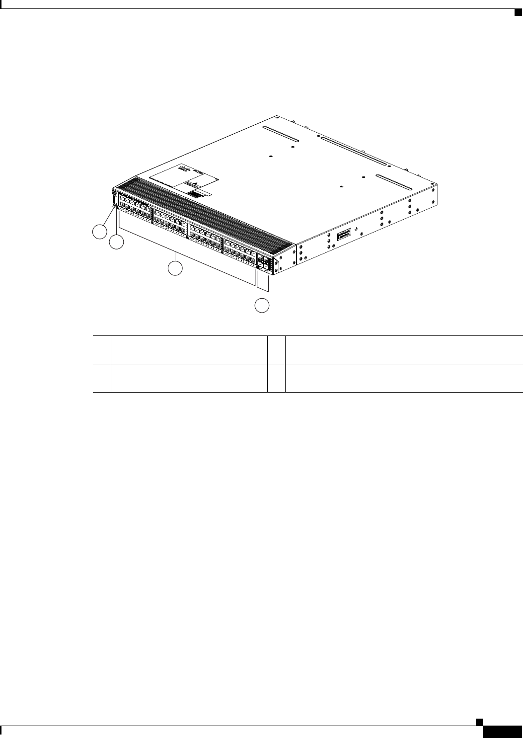
3-3
Cisco Nexus 2000 Series Hardware Installation Guide
Chapter 3 Using a Fabric Extender with a Cisco Nexus 9000 Series Switch
Cisco Nexus 2248TP-E FEX
The rear of the Cisco Nexus 2248TP-E FEX chassis has 48 100/1000 Ethernet downlink ports, four
10-Gigabit Ethernet uplink ports, an HDMI port, and LEDs, as shown in Figure 3-2.
Figure 3-2 Rear View of the Cisco Nexus 2248TP-E Chassis
For LED descriptions, see Appendix E, “LEDs.”
This section includes the following topics:
•Ports for the Cisco Nexus 2248TP-E FEX, page 3-3
•Power Supplies for the Cisco Nexus 2248TP-E FEX, page 3-4
•Fan Tray for the Cisco Nexus 2248TP-E FEX, page 3-6
•Transceivers and Connectors Supported by the Cisco Nexus 2248TP-E FEX, page 3-8
Ports for the Cisco Nexus 2248TP-E FEX
The downlink and uplink ports are numbered from top to bottom and then left to right as shown in
Figure 3-3.
3
2
4
1
239287
1Status (top) and ID (bottom) LEDs 3100/1000BASE-T Ethernet ports (copper downlink
ports for RJ-45 connectors) (48)
2HDMI port 410-Gigabit Ethernet fabric ports (copper/optical uplink
ports for SFP+ transceivers) (4)
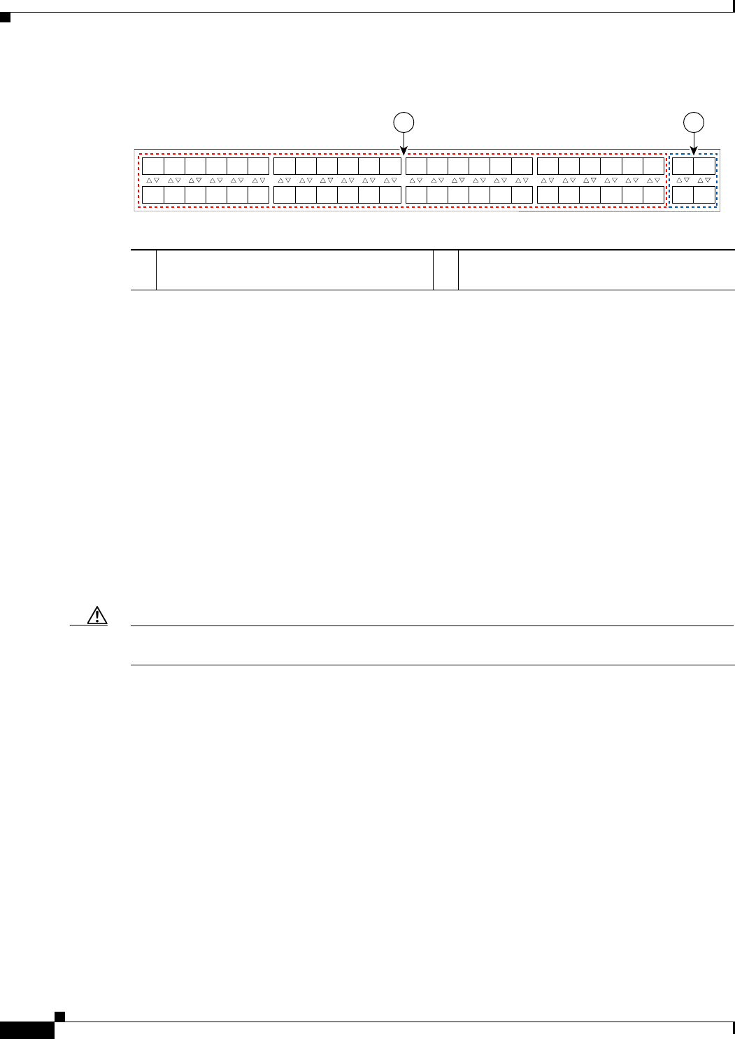
3-4
Cisco Nexus 2000 Series Hardware Installation Guide
Chapter 3 Using a Fabric Extender with a Cisco Nexus 9000 Series Switch
Cisco Nexus 2248TP-E FEX
Figure 3-3 Port Numbering on the Cisco Nexus 2248TP-E FEX
For information about the transceivers and connectors that you can use with these ports, see the
“Transceivers and Connectors Supported by the Cisco Nexus 2248TP-E FEX” section on page 3-8.
Power Supplies for the Cisco Nexus 2248TP-E FEX
The Cisco Nexus 2200 Series FEX chassis have two slots for front-end AC or DC power supplies that
have port-side-exhaust or port-side-intake airflow. These chassis are fully functional with one power
supply, but you can install a second power supply for power redundancy. If you have only one power
supply in the chassis, install a blank filler panel (N2200-P-BLNK) to maintain the designed airflow in
the chassis. You can install any of the following power supplies in those two bays:
•AC power supply with port-side-exhaust airflow (N2200-PAC-400W)
•AC power supply with port-side-intake airflow (N2200-PAC-400W-B)
•DC power supply with port-side-exhaust airflow (N2200-PDC-400W)
•DC power supply with port-side-intake airflow (N2200-PDC-350W-B)
Caution Make sure that all of the fan tray and power supply modules use the same airflow direction and have the
same color designation on the front. Otherwise, the switch can over heat and shut down,
Figure 3-4 shows the exterior components on an AC power supply with port-side-exhaust airflow (no
black stripe on the front). Figure 3-5 shows the components on a DC power supply with
port-side-exhaust airflow. Figure 3-6 shows the black stripe used to indicate port-side-intake airflow (in
this case on an AC power supply). Figure 3-7 shows the blank filler panel that you should install in an
open power supply slot if the chassis has only one power supply.
A B
192533
1
2
3
4
5
6
7
8
9
10
11
12
13
14
15
16
17
18
19
20
21
22
23
24
25
26
27
28
29
30
31
32
33
34
35
36
37
38
39
40
41
42
43
44
45
46
47
48
1
2
3
4
A100/1000BASE-T Ethernet downlink ports,
numbered 1 through 48
B10-Gigabit Ethernet uplink ports, numbered 1
through 4
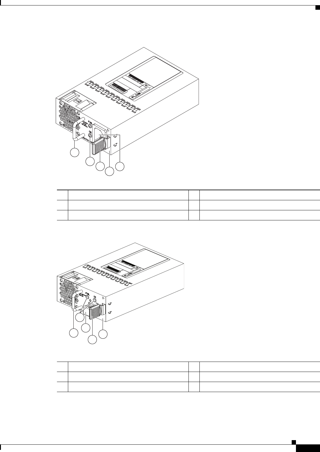
3-5
Cisco Nexus 2000 Series Hardware Installation Guide
Chapter 3 Using a Fabric Extender with a Cisco Nexus 9000 Series Switch
Cisco Nexus 2248TP-E FEX
Figure 3-4 AC Power Supply with Port-Side-Exhaust Airflow for the Cisco Nexus 2200 Platform
Figure 3-5 DC Power Supply with Front-to-Back Airflow for the Cisco Nexus 2200 Platform
1
2
3
4
5
239843
1Handle 4No black stripe (port-side-exhaust airflow)
2FAIL (top) and OK (bottom) LEDs 5AC power receptacle
3Ejector latch
1
2
4
3
5
239933
1Handle 4Ejector latch
2FAIL (left) and OK (right) LEDs 5No black stripe (port-side-exhaust airflow)
3DC power connector with safety cover
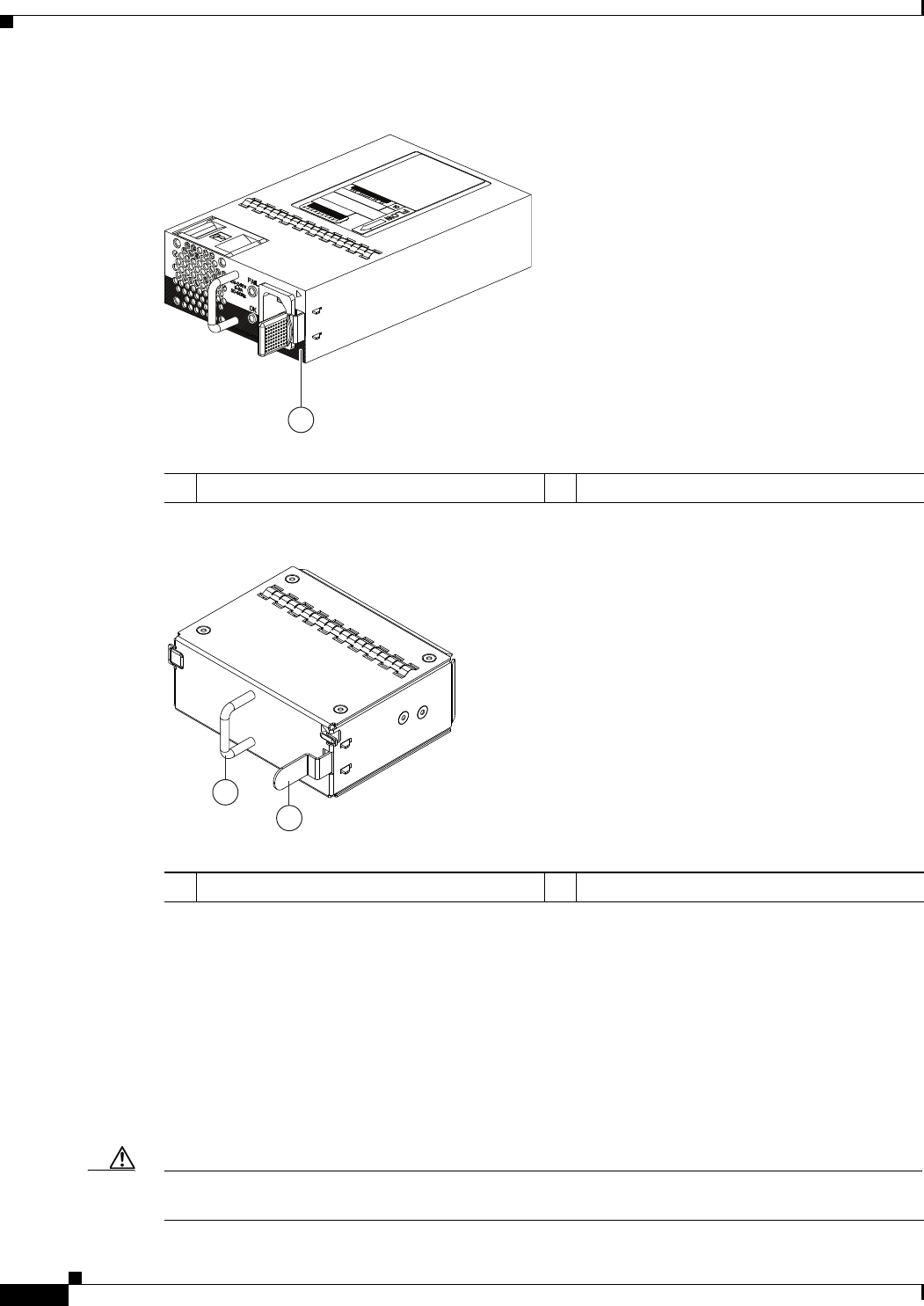
3-6
Cisco Nexus 2000 Series Hardware Installation Guide
Chapter 3 Using a Fabric Extender with a Cisco Nexus 9000 Series Switch
Cisco Nexus 2248TP-E FEX
Figure 3-6 Black Stripe Used to Indicate Port-Side-Intake Airflow
Figure 3-7 Blank Power Supply Filler Panel for a Cisco Nexus 2200 Platform Power Supply Bay
For LED descriptions, see Appendix E, “LEDs”.
For power supply specifications, see the Appendix B, “Technical Specifications”.
Fan Tray for the Cisco Nexus 2248TP-E FEX
The Cisco Nexus 2224TP, 2248TP, and 2248TP-E FEXs use the same fan tray that you can order with
either port-side-exhaust airflow (N2K-C2248-FAN) or port-side-intake airflow (N2K-C2248-FAN-B).
The fan tray includes a status LED that indicates whether the module is operational.
Caution Make sure that all of the fan tray and power supply modules use the same airflow direction and have the
same color designation on the front. Otherwise, the switch can over heat and shut down,
1
334329
A220 P C-400
1Black stripe (port-side-intake airflow)
2
1
239290
1Handle 2Ejector latch
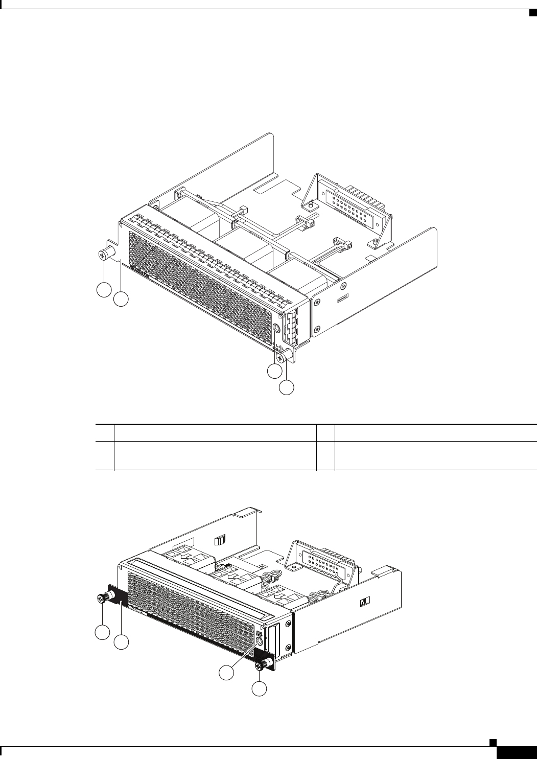
3-7
Cisco Nexus 2000 Series Hardware Installation Guide
Chapter 3 Using a Fabric Extender with a Cisco Nexus 9000 Series Switch
Cisco Nexus 2248TP-E FEX
Figure 3-8 shows the fan tray with port-side-exhaust airflow (no black stripe on front) and identifies its
components, and Figure 3-9 shows the fan tray with port-side-intake airflow (black stripe on front) and
identifies its components.
Figure 3-8 Port-Side-Exhaust Airflow Fan Tray for the Cisco Nexus 2000 Series FEX
Figure 3-9 Port-Side Intake Airflow Fan Tray for the Cisco Nexus 2000 Series FEX
3
2
1
1
239291
1Captive screws (2) 3Status LED
2No black stripe on the front indicates that this
fan tray has port-side-exhaust airflow.
2
1
3
239934
1
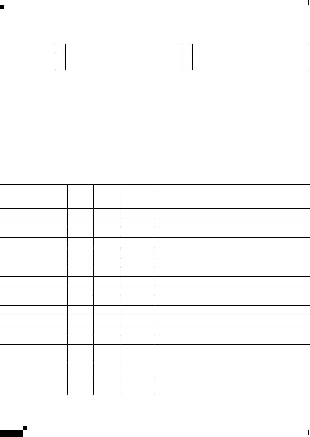
3-8
Cisco Nexus 2000 Series Hardware Installation Guide
Chapter 3 Using a Fabric Extender with a Cisco Nexus 9000 Series Switch
Cisco Nexus 2248TP-E FEX
For information on this fan tray, see the “Fan Tray for the Cisco Nexus 2248TP FEX” section on
page 3-13 and the fan tray specifications in Appendix B, “Technical Specifications”. For LED
descriptions, see Appendix E, “LEDs”.
Transceivers and Connectors Supported by the Cisco Nexus 2248TP-E FEX
The Cisco Nexus 2248TP-E FEX supports SFP+ Ethernet copper and optical transceivers for up to four
fabric uplink connections to Cisco Nexus 9396PX switches, and it supports 100/1000BASE-T RJ-45
connectors for up to 48 downlink connections to hosts. Table 3-2 lists the transceivers supported by this
FEX for its uplink and downlink connections.
1Captive screws (2) 3Status LED
2Black stripe on the front indicates that this fan
tray has port-side intake airflow.
Table 3-2 Supported Transceivers and Connector for the Cisco Nexus 2248TP-E FEX Interfaces
Transceiver or Connector
Cable
Type
Fabric
Interface
(Uplink)
Host
Interface
(Downlink) Comments
FET-10G Optical X – 10-Gbps FEX transceiver
SFP-10G-LR Optical X – 10-Gbps long range transceiver (up to 6.2 miles [10 km])
SFP-10G-SR Optical X – 10-Gbps Short range transceiver (up to 984 feet [300 m])
SFP -H10GB-CU1M Copper X – 10-Gbps Twinax, passive transceiver (3.3 feet [1 meter])
SFP -H10GB-CU3M Copper X – 10-Gbps Twinax, passive transceiver (9.8 feet [3 meters)
SFP -H10GB-CU5M Copper X – 10-Gbps Twinax, passive transceiver (16.4 feet [5 meters])
SFP -H10GB-ACU7M Copper X – 10-Gbps Twinax, active transceiver (23.0 feet [7 meters])
SFP -H10GB-ACU10M Copper X – 10-Gbps Twinax, active transceiver (32.8 feet [10 meters])
SFP-10G-AOC1M Optical X – 10-Gbps active optical cable (3.3 feet [1 meter])
SFP-10G-AOC2M Optical X – 10-Gbps active optical cable (6.6 feet [2 meters])
SFP-10G-AOC3M Optical X – 10-Gbps active optical cable (9.8 feet [3 meters])
SFP-10G-AOC5M Optical X – 10-Gbps active optical cable (16.4 feet [5 meters])
SFP-10G-AOC7M Optical X – 10-Gbps active optical cable (23.0 feet [7 meters])
SFP-10G-AOC10M Optical X – 10-Gbps active optical cable (32.8 feet [10 meters])
QSFP-4X10G-AOC1M Optical X – 40- and 10-Gbps active optical breakout cable (3.3 feet
[1 meter])
QSFP-4X10G-AOC2M Optical X – 40- and 10-Gbps active optical breakout cable (6.6 feet
[2 meters])
QSFP-4X10G-AOC3M Optical X – 40- and 10-Gbps active optical breakout cable (9.8 feet
[3 meters])
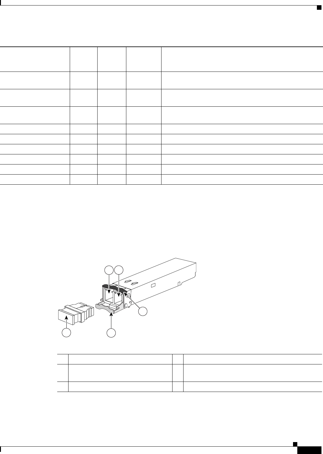
3-9
Cisco Nexus 2000 Series Hardware Installation Guide
Chapter 3 Using a Fabric Extender with a Cisco Nexus 9000 Series Switch
Cisco Nexus 2248TP-E FEX
For more information on the transceivers that you can use with this FEX, see the Cisco Transceiver
Modules Compatibility Information at
http://www.cisco.com/c/en/us/support/interfaces-modules/transceiver-modules/products-device-suppor
t-tables-list.html.
Figure 3-10 shows the SFP+ optical transceiver used for uplink connections.
Figure 3-10 SFP+ Optical Transceivers and FETs
Figure 3-11 identifies the major features of the SFP+ copper transceiver and cable used for uplink
connections. For the cable specifications that apply to these transceivers, see Appendix C, “Cable and
Port Specifications”.
QSFP-4X10G-AOC5M Optical X – 40- and 10-Gbps active optical breakout cable (16.4 feet
[5 meters])
QSFP-4X10G-AOC7M Optical X – 40- and 10-Gbps active optical breakout cable (23.0 feet
[7 meters])
QSFP-4X10G-AOC10M Optical X – 40- and 10-Gbps active optical breakout cable (32.8 feet
[10 meters])
QSFP-4SFP10G-CU1M Optical X – 40- and 10-Gbps copper breakout cable (3.3 feet [1 meter])
QSFP-4SFP10G-CU3M Optical X – 40- and 10-Gbps copper breakout cable (9.8 feet [3 meters])
QSFP-4SFP10G-CU5M Optical X – 40- and 10-Gbps copper breakout cable (16.4 feet [5 meters])
QSFP-4SFP10G-CU7M Optical X – 40- and 10-Gbps copper breakout cable (23.0 feet [7 meters])
QSFP-4SFP10G-CU10M Optical X – 40- and 10-Gbps copper breakout cable (32.8 feet [10 meters])
RJ-45 Copper – X 100/1000 Mbps Connector
Table 3-2 Supported Transceivers and Connector for the Cisco Nexus 2248TP-E FEX Interfaces
Transceiver or Connector
Cable
Type
Fabric
Interface
(Uplink)
Host
Interface
(Downlink) Comments
197285
12
54
3
1Receive optical bore 4Clasp shown in open position
2Transmit optical bore 5Dust plug (use this to protect the bores from dust
contamination when the optical cables are removed)
3Clasp shown in closed position
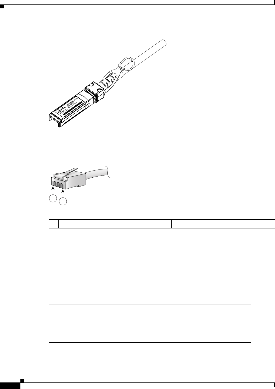
3-10
Cisco Nexus 2000 Series Hardware Installation Guide
Chapter 3 Using a Fabric Extender with a Cisco Nexus 9000 Series Switch
Cisco Nexus 2248TP FEX
Figure 3-11 SFP+ Copper Transceiver Module
Figure 3-12 identifies the major features of RJ-45 connectors, which are used for the downlink
connections.
Figure 3-12 RJ-45 Connector
Cisco Nexus 2248TP FEX
The Cisco Nexus 2248TP FEX (N2K-C2248TP) is a stackable 1-RU FEX that has 48 100/1000 Ethernet
host interfaces (downlink ports for copper RJ-45 connectors) and four 10-Gigabit Ethernet fabric
interfaces (uplink ports for copper/optical SFP+ transceivers). It requires a 19-inch (48.26-cm) rack for
its installation. Table 3-3 lists its physical characteristics.
187492
94971
12
RJ-45 (both ends)
1Pin 1 2Pin 8
Table 3-3 Physical Characteristics for the Cisco Nexus 2248TP FEX
Dimensions
Width
Depth
Height
17.3 inches (43.9 cm)
20.0 inches (50.8 cm)
1.72 inches (4.4 cm)
Weight117.7 lb (8.0 kg)
1. Measured with two power supplies and one fan module installed.
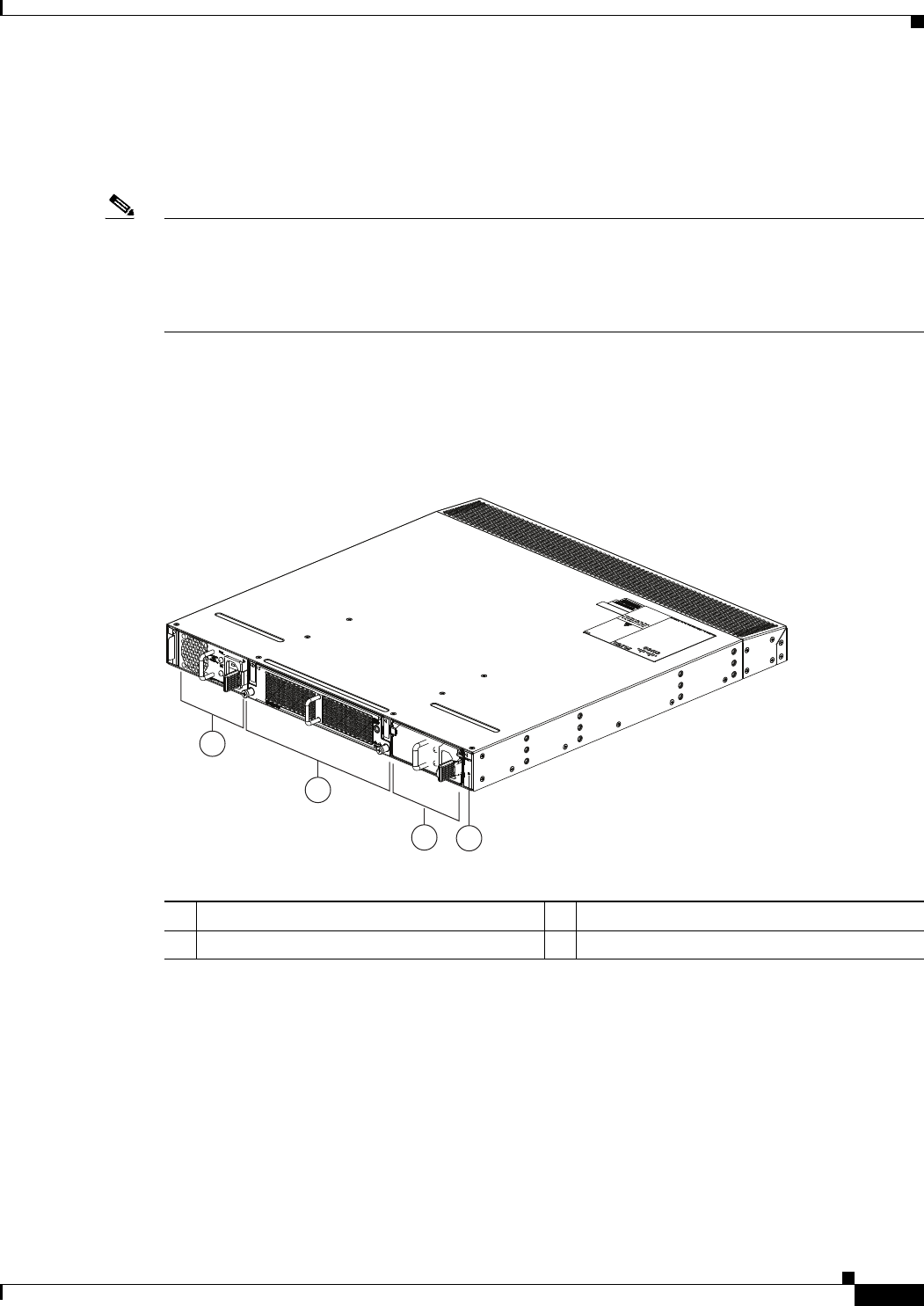
3-11
Cisco Nexus 2000 Series Hardware Installation Guide
Chapter 3 Using a Fabric Extender with a Cisco Nexus 9000 Series Switch
Cisco Nexus 2248TP FEX
You can order the Cisco Nexus 2248TP FEX with front-to-back (port-side exhaust) or back-to-front
(port-side intake) airflow and with AC or DC power supplies. If you are going to install the port side in
a hot aisle, then order port-side-exhaust airflow for the fan trays and power supplies. If you are going to
install the port side in the cold aisle, order port-side-intake airflow for the fan trays and power supplies.
Note For visual identification, port-side-intake airflow fan trays and power supplies have a black stripe across
their front, and port-side-exhaust airflow modules do not have a black stripe across their front. All of the
power supplies and fan trays must have the same direction of airflow for the components to properly
function (all of these components must either have a black stripe or all of the components must not have
a black stripe).
The front of the Cisco Nexus 2248TP FEX chassis has one or two power supplies, a fan tray, and two
chassis LEDs as shown in Figure 3-13. This FEX model requires one power supply, but if you want
power redundancy, you must install a second power supply.
Figure 3-13 Front View of the Cisco Nexus 2248TP Chassis
The rear of the Cisco Nexus 2248TP-E FEX has 48 100/1000 Ethernet downlink ports, four 10-Gigabit
Ethernet uplink ports, an HDMI port, and LEDs, as shown in Figure 3-14.
2
1
34
239288
1Power supply 3Power supply (blank shown)
2Fan tray 4Status (top) and ID (bottom) LEDs
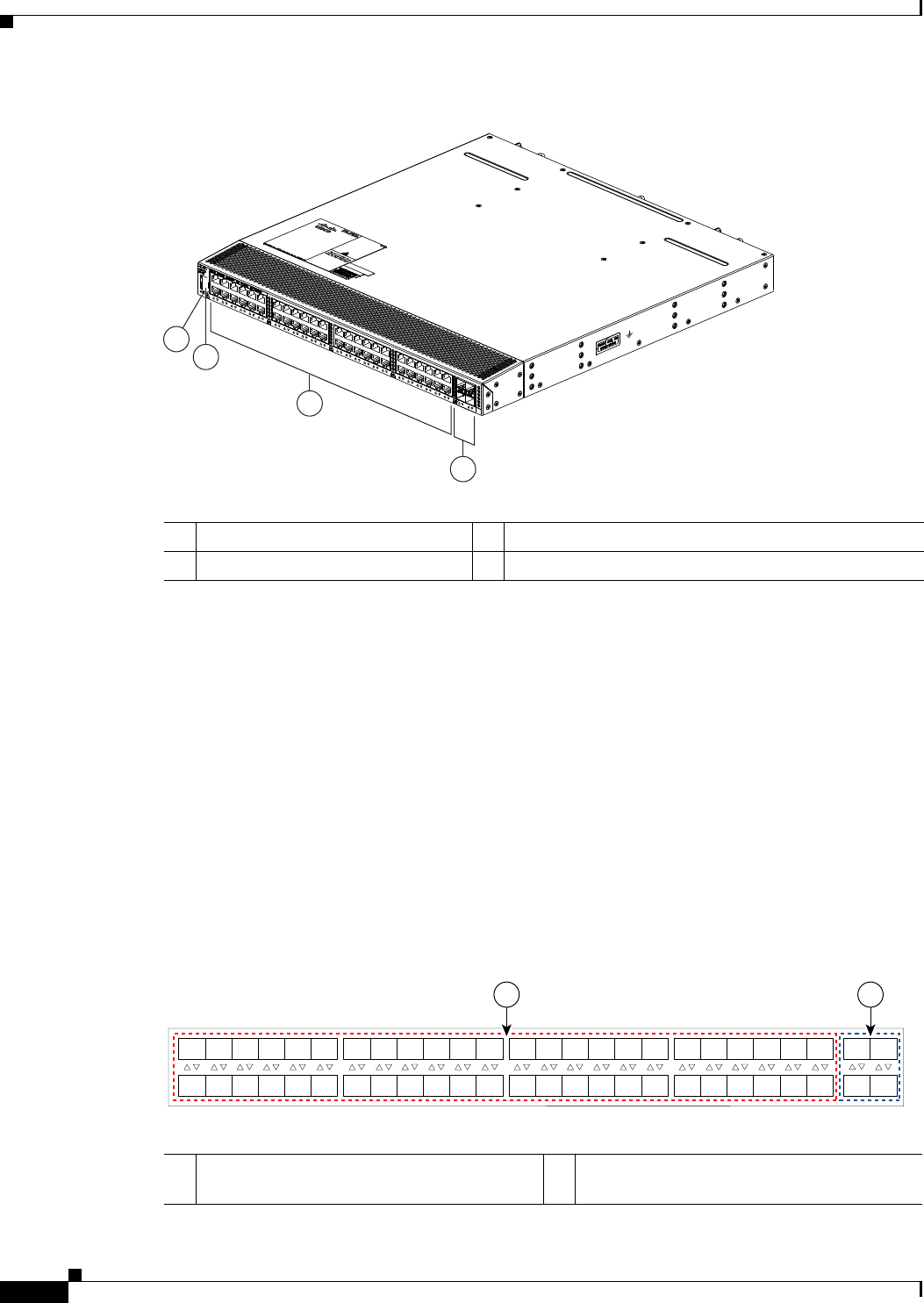
3-12
Cisco Nexus 2000 Series Hardware Installation Guide
Chapter 3 Using a Fabric Extender with a Cisco Nexus 9000 Series Switch
Cisco Nexus 2248TP FEX
Figure 3-14 Rear View of the Cisco Nexus 2248TP Chassis
For LED descriptions, see Appendix E, “LEDs”.
This section includes the following topics:
•Ports for the Cisco Nexus 2248TP FEX, page 3-12
•Power Supplies for the Cisco Nexus 2248TP FEX, page 3-13
•Fan Tray for the Cisco Nexus 2248TP FEX, page 3-13
•Transceivers and Connectors Supported by the Cisco Nexus 2248TP FEX, page 3-13
Ports for the Cisco Nexus 2248TP FEX
The downlink and uplink ports are numbered from top to bottom and then left to right as shown in
Figure 3-15.
Figure 3-15 Port Numbering on the Cisco Nexus 2248TP FEX
3
2
4
1
239287
1Status (top) and ID (bottom) LEDs 3100/1000 BASE-T host-facing (downlink) ports (48)
2HDMI port 410-Gigabit SFP+ network-facing (uplink) ports (4)
A B
192533
1
2
3
4
5
6
7
8
9
10
11
12
13
14
15
16
17
18
19
20
21
22
23
24
25
26
27
28
29
30
31
32
33
34
35
36
37
38
39
40
41
42
43
44
45
46
47
48
1
2
3
4
A100/1000BASE-T Ethernet ports, numbered 1
through 48
B10-Gigabit SFP+ Ethernet uplink ports,
numbered 1 through 4
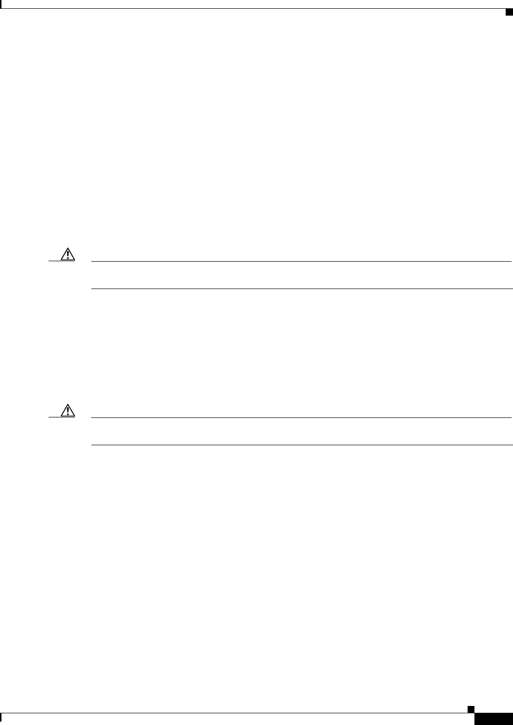
3-13
Cisco Nexus 2000 Series Hardware Installation Guide
Chapter 3 Using a Fabric Extender with a Cisco Nexus 9000 Series Switch
Cisco Nexus 2248TP FEX
For information about the transceivers and connectors that you can use with these ports, see the
“Transceivers and Connectors Supported by the Cisco Nexus 2248TP FEX” section on page 3-13.
Power Supplies for the Cisco Nexus 2248TP FEX
The Cisco Nexus 2200 Platform FEX chassis have two slots for front-end AC or DC power supplies that
have port-side-exhaust or port-side-intake airflow. These chassis are fully functional with one power
supply, but you can install a second power supply for power redundancy. You can install any of the
following power supplies in those two bays:
•AC power supply with port-side-exhaust airflow (N2200-PAC-400W)
•AC power supply with port-side-intake airflow (N2200-PAC-400W-B)
•DC power supply with port-side-exhaust airflow (N2200-PDC-400W)
•DC power supply with port-side-intake airflow (N2200-PDC-350W-B)
Caution Make sure that all of the fan tray and power supply modules use the same airflow direction and have the
same color designation on the front. Otherwise, the switch can over heat and shut down,
For information on these power supplies, see the “Power Supplies for the Cisco Nexus 2248TP FEX”
section on page 3-13 and the power supply specifications in the Appendix B, “Technical Specifications”.
Fan Tray for the Cisco Nexus 2248TP FEX
The Cisco Nexus 2224TP, 2248TP, and 2248TP-E FEXs use the same fan tray that you can order with
either port-side-exhaust airflow (N2K-C2248-FAN) or port-side-intake airflow (N2K-C2248-FAN-B).
Caution Make sure that all of the fan tray and power supply modules use the same airflow direction and have the
same color designation on the front. Otherwise, the switch can over heat and shut down,
For information on this fan tray, see the “Fan Tray for the Cisco Nexus 2248TP-E FEX” section on
page 3-6 and the fan tray specifications in Appendix B, “Technical Specifications”. For LED
descriptions, see Appendix E, “LEDs”.
Transceivers and Connectors Supported by the Cisco Nexus 2248TP FEX
The Cisco Nexus 2248TP FEX supports SFP+ Ethernet copper and optical transceivers for up to four
fabric uplink connections to Cisco Nexus 9396PX switches, and it supports 100/1000BASE-T RJ-45
connectors for up to 48 downlink connections to hosts. For each uplink cable, you must use the same
transceiver on both ends. Table 3-2 lists the transceivers supported by this FEX for its uplink fabric.

3-14
Cisco Nexus 2000 Series Hardware Installation Guide
Chapter 3 Using a Fabric Extender with a Cisco Nexus 9000 Series Switch
Cisco Nexus 2248TP FEX
Table 3-4 Supported Transceivers and Connector for the Cisco Nexus 2248TP FEX Interfaces
Transceiver or Connector
Cable
Type
Fabric
Interface
(Uplink)
Host
Interface
(Downlink) Comments
FET-10G Optical X – 10-Gbps FEX transceiver
SFP-10G-LR Optical X – 10-Gbps long range transceiver (up to 6.2 miles [10 km])
SFP-10G-SR Optical X – 10-Gbps Short range transceiver (up to 984 feet [300 m])
SFP -H10GB-CU1M Copper X – 10-Gbps Twinax, passive transceiver (3.3 feet [1 meter])
SFP -H10GB-CU3M Copper X – 10-Gbps Twinax, passive transceiver (9.8 feet [3 meters)
SFP -H10GB-CU5M Copper X – 10-Gbps Twinax, passive transceiver (16.4 feet [5 meters])
SFP -H10GB-ACU7M Copper X – 10-Gbps Twinax, active transceiver (23.0 feet [7 meters])
SFP -H10GB-ACU10M Copper X – 10-Gbps Twinax, active transceiver (32.8 feet [10 meters])
SFP-10G-AOC1M Optical X – 10-Gbps active optical cable (3.3 feet [1 meter])
SFP-10G-AOC2M Optical X – 10-Gbps active optical cable (6.6 feet [2 meters])
SFP-10G-AOC3M Optical X – 10-Gbps active optical cable (9.8 feet [3 meters])
SFP-10G-AOC5M Optical X – 10-Gbps active optical cable (16.4 feet [5 meters])
SFP-10G-AOC7M Optical X – 10-Gbps active optical cable (23.0 feet [7 meters])
SFP-10G-AOC10M Optical X – 10-Gbps active optical cable (32.8 feet [10 meters])
QSFP-4X10G-AOC1M Optical X – 40- and 10-Gbps active optical breakout cable (3.3 feet
[1 meter])
QSFP-4X10G-AOC2M Optical X – 40- and 10-Gbps active optical breakout cable (6.6 feet
[2 meters])
QSFP-4X10G-AOC3M Optical X – 40- and 10-Gbps active optical breakout cable (9.8 feet
[3 meters])
QSFP-4X10G-AOC5M Optical X – 40- and 10-Gbps active optical breakout cable (16.4 feet
[5 meters])
QSFP-4X10G-AOC7M Optical X – 40- and 10-Gbps active optical breakout cable (23.0 feet
[7 meters])
QSFP-4X10G-AOC10M Optical X – 40- and 10-Gbps active optical breakout cable (32.8 feet
[10 meters])
QSFP-4SFP10G-CU1M Optical X – 40- and 10-Gbps copper breakout cable (3.3 feet [1 meter])
QSFP-4SFP10G-CU3M Optical X – 40- and 10-Gbps copper breakout cable (9.8 feet [3 meters])
QSFP-4SFP10G-CU5M Optical X – 40- and 10-Gbps copper breakout cable (16.4 feet [5 meters])
QSFP-4SFP10G-CU7M Optical X – 40- and 10-Gbps copper breakout cable (23.0 feet [7 meters])
QSFP-4SFP10G-CU10M Optical X – 40- and 10-Gbps copper breakout cable (32.8 feet [10 meters])
RJ-45 Copper – X 100/1000 Mbps Connector

3-15
Cisco Nexus 2000 Series Hardware Installation Guide
Chapter 3 Using a Fabric Extender with a Cisco Nexus 9000 Series Switch
Cisco Nexus 2232TM FEX
For more information on the transceivers that you can use with this FEX, see the Cisco Transceiver
Modules Compatibility Information at
http://www.cisco.com/c/en/us/support/interfaces-modules/transceiver-modules/products-device-suppor
t-tables-list.html.
Figure 3-10 on page 3-9 shows the SFP+ optical transceiver used for uplink connections.
Figure 3-11 on page 3-10 identifies the major features of the SFP+ copper transceiver and cable used for
uplink connections.
Figure 3-12 on page 3-10 identifies the major features of RJ-45 connectors, which are used for the
downlink connections.
Cisco Nexus 2232TM FEX
The Cisco Nexus 2232TM FEX (N2K-C2232TM) is a stackable 1-RU FEX that has 32 1- and 10-Gigabit
Ethernet host interfaces (1/10GBASE-T downlink ports for RJ-45 connectors) and eight 10-Gigabit
Ethernet fabric interfaces (copper/optical uplink ports for SFP+ transceivers). It requires a 19-inch
(48.26-cm) rack for its installation. Table 3-7 lists its physical characteristics.
You can order the Cisco Nexus 2232TM with port-side exhaust or port-side-intake airflow and with AC
or DC power supplies. If you are going to install the port side in a hot aisle, then order port-side exhaust
airflow for the fan trays and power supplies. If you are going to install the port side in the cold aisle,
order port-side intake airflow for the fan trays and power supplies.
The front of the Cisco Nexus 2232TM FEX chassis has one or two power supplies, a fan tray, and two
LEDs as shown in Figure 3-16. This FEX model requires one power supply, but if you want power
redundancy, you must install a second power supply.
Table 3-5 Physical Characteristics for the Cisco Nexus 2232TM FEX
Dimensions
Width
Depth
Height
17.3 inches (43.94 cm)
17.7 inches (44.96 cm)
1.72 inches (4.37 cm)
Weight118.3 lb (8.3 kg)
1. Measured with two power supplies and one fan module installed
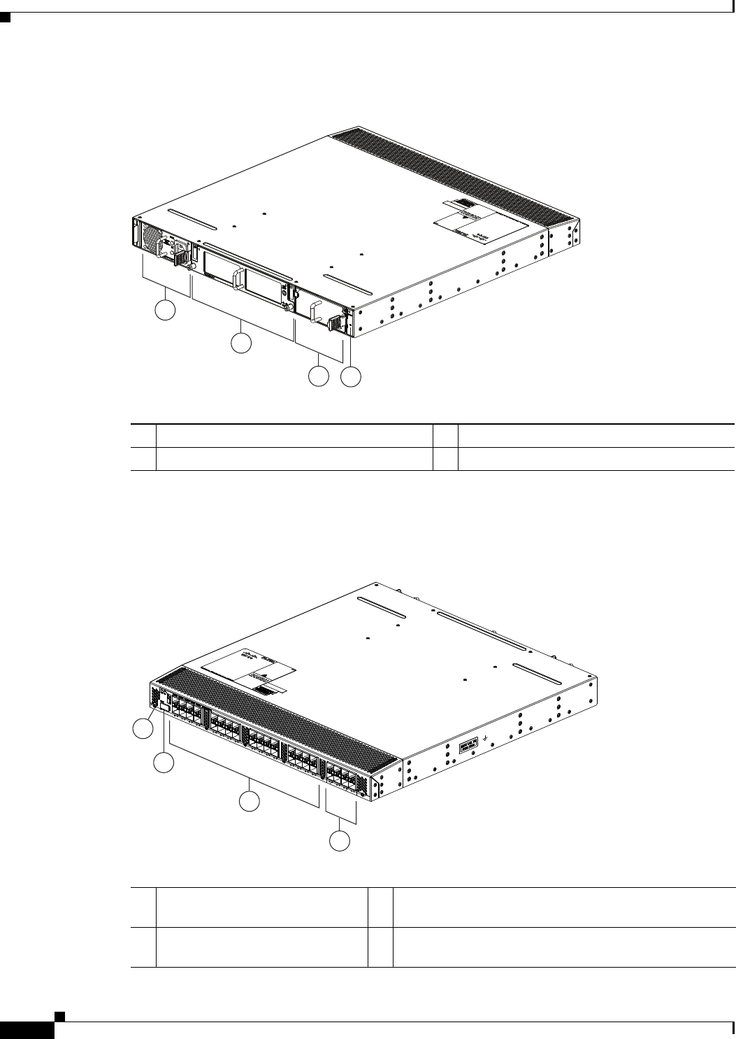
3-16
Cisco Nexus 2000 Series Hardware Installation Guide
Chapter 3 Using a Fabric Extender with a Cisco Nexus 9000 Series Switch
Cisco Nexus 2232TM FEX
Figure 3-16 Front View of the Cisco Nexus 2232TM Chassis
The rear of the Cisco Nexus 2232TM FEX has 32 1- and 10-Gigabit Ethernet downlink ports, eight
10-Gigabit Ethernet uplink ports, an HDMI port, and two LEDs, as shown in Figure 3-22.
Figure 3-17 Rear View of the Cisco Nexus 2232TM Chassis
2
1
34
239279
1Power supply 3Power supply (blank shown)
2Fan tray 4Status (top) and ID (bottom) LEDs
3
2
4
239278
1
1Status (top) and ID (bottom) LEDs 31- and 10-Gigabit Ethernet host ports (1/10GBASE-T
downlink ports for RJ-45 connectors) (48)
2HDMI port 410-Gigabit Ethernet fabric ports (copper/optical uplink
ports for SFP+ transceivers) (8)
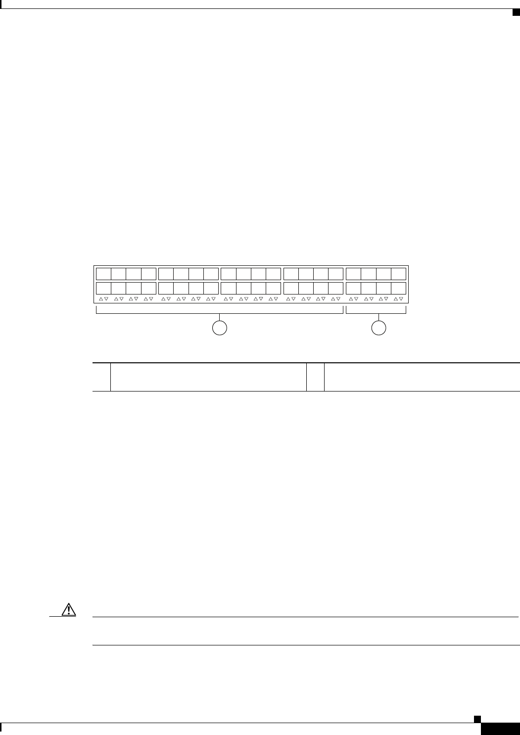
3-17
Cisco Nexus 2000 Series Hardware Installation Guide
Chapter 3 Using a Fabric Extender with a Cisco Nexus 9000 Series Switch
Cisco Nexus 2232TM FEX
For LED descriptions, see Appendix E, “LEDs”.
This section includes the following topics:
•Ports for the Cisco Nexus 2232TM FEX, page 3-17
•Power Supplies for the Cisco Nexus 2232TM FEX, page 3-17
•Fan Tray for the Cisco Nexus 2232TM FEX, page 3-18
•Transceivers and Connectors Supported by the Cisco Nexus 2232TM FEX, page 3-19
Ports for the Cisco Nexus 2232TM FEX
The downlink and uplink ports are numbered from top to bottom and then from left to right as shown in
Figure 3-23.
Figure 3-18 Port Numbering on the Cisco Nexus 2232TM FEX
For information about the transceivers and connectors that you can use with these ports, see the
“Transceivers and Connectors Supported by the Cisco Nexus 2232TM FEX” section on page 3-19.
Power Supplies for the Cisco Nexus 2232TM FEX
The Cisco Nexus 2200 Platform FEX chassis have two slots for front-end AC or DC power supplies that
have port-side-exhaust or port-side-intake airflow. These chassis are fully functional with one power
supply, but you can install a second power supply for power redundancy. You can install any of the
following power supplies in those two bays:
•AC power supply with port-side-exhaust airflow (N2200-PAC-400W)
•AC power supply with port-side-intake airflow (N2200-PAC-400W-B)
•DC power supply with port-side-exhaust airflow (N2200-PDC-400W)
•DC power supply with port-side-intake airflow (N2200-PDC-350W-B)
Caution Make sure that all of the fan tray and power supply modules use the same airflow direction and have the
same color designation on the front. Otherwise, the switch can over heat and shut down,
If you have only one power supply in a chassis, then you must install a blank filler plate
(N2200-P-BLNK) in the open slot to maintain the designed airflow.
12
330042
1
2
3
4
5
6
7
8
1
2
3
4
5
6
7
8
911
14
13 15
12
10 16
17
18
19
20
21 23
22
24
25
26
27
28
29 31
30 32
11- and 10-Gigabit Ethernet downlink ports,
numbered 1 through 32
210-Gigabit Ethernet uplink ports, numbered 1
through 8
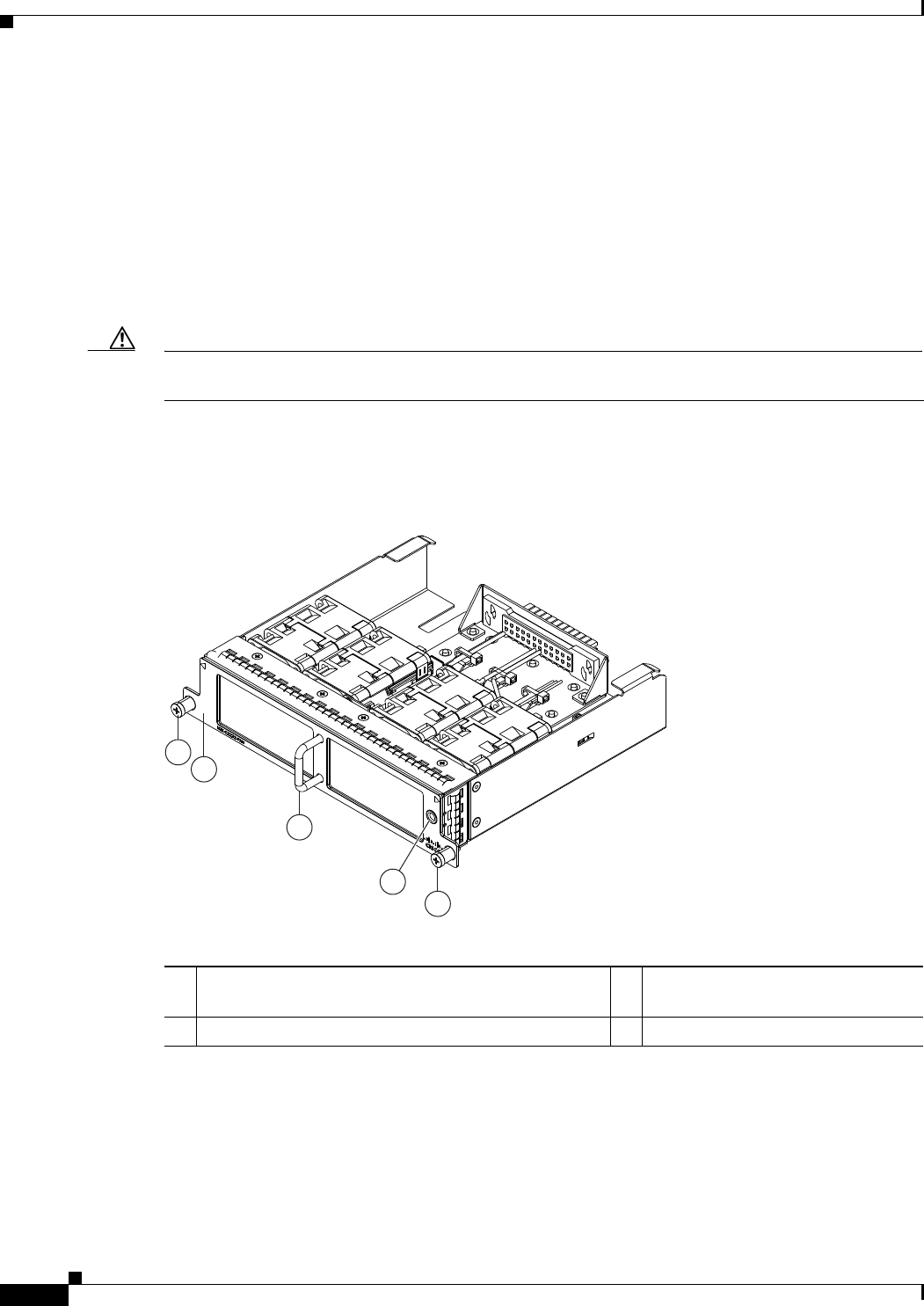
3-18
Cisco Nexus 2000 Series Hardware Installation Guide
Chapter 3 Using a Fabric Extender with a Cisco Nexus 9000 Series Switch
Cisco Nexus 2232TM FEX
For more information on these power supplies, see the “Power Supplies for the Cisco Nexus 2248TP-E
FEX” section on page 3-4 and the power supply specifications in the Appendix B, “Technical
Specifications”.
Fan Tray for the Cisco Nexus 2232TM FEX
The Cisco Nexus 2232PP and 2232TM FEX use the same fan tray, which you can order with either
port-side-exhaust airflow (N2K-C2232-FAN) or port-side-intake airflow (N2K-C2232-FAN-B). The fan
tray includes a status LED that indicates whether the module is operational.
Caution Make sure that all of the fan tray and power supply modules use the same airflow direction and have the
same color designation on the front. Otherwise, the switch can over heat and shut down,
Figure 3-19 shows the fan tray with port-side-exhaust airflow (no black stripe across the front), and
Figure 3-20 shows the fan tray with port-side-intake airflow (black stripe across the front).
Figure 3-19 Front-to-Back Airflow Fan Tray for the Cisco Nexus 2232PP and 2232TM FEXs
4
2
1
3
1
239292
1Captive screws (2) 3Front-to-back airflow indicated by a
lack of black stripe on the front.
2Handle used for removing and installing the module 4Status LED
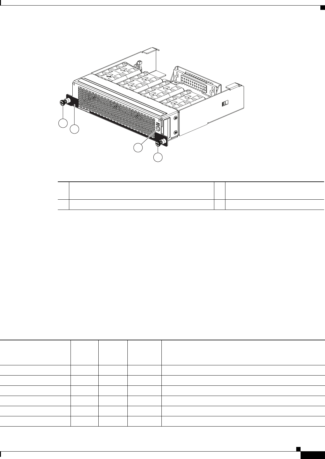
3-19
Cisco Nexus 2000 Series Hardware Installation Guide
Chapter 3 Using a Fabric Extender with a Cisco Nexus 9000 Series Switch
Cisco Nexus 2232TM FEX
Figure 3-20 Back-to-Front Airflow Fan Tray for the Cisco Nexus 2232PP and 2232TM FEXs
For more information on this fan tray, see the fan tray specifications in Appendix B, “Technical
Specifications”. For LED descriptions, see Appendix E, “LEDs”. To replace one of these fan trays, see
“Removing and Installing the Fan Tray” section on page 4-21.
Transceivers and Connectors Supported by the Cisco Nexus 2232TM FEX
The Cisco Nexus 2232TM FEX supports SFP+ Ethernet optical and copper transceivers and optical FEX
Transceivers (FETs) for up to eight fabric uplink connections to the Cisco Nexus 9396PX switch.
The Cisco Nexus 2232TM FEX also supports RJ-45 connectors for up to 32 downlink connections to
hosts. Table 3-2 lists the transceivers and connectors supported by this FEX for its uplink and downlink
connections.
239936
2
1
3
1
1Captive screws (2) 3Back-to-front airflow indicated by a
black stripe on the front.
2Handle used for removing and installing the module 4Status LED
Table 3-6 Supported Transceivers and Connector for the Cisco Nexus 2232TM FEX Interfaces
Transceiver or Connector
Cable
Type
Fabric
Interface
(Uplink)
Host
Interface
(Downlink) Comments
FET-10G Optical X – 10-Gbps FEX transceiver
SFP-10G-LR Optical X – 10-Gbps long range transceiver (up to 6.2 miles [10 km])
SFP-10G-SR Optical X – 10-Gbps Short range transceiver (up to 984 feet [300 m])
SFP-H10GB-CU1M Copper X – 10-Gbps Twinax, passive transceiver (3.3 feet [1 meter])
SFP-H10GB-CU3M Copper X – 10-Gbps Twinax, passive transceiver (9.8 feet [3 meters)
SFP-H10GB-CU5M Copper X – 10-Gbps Twinax, passive transceiver (16.4 feet [5 meters])

3-20
Cisco Nexus 2000 Series Hardware Installation Guide
Chapter 3 Using a Fabric Extender with a Cisco Nexus 9000 Series Switch
Cisco Nexus 2232TM FEX
For more information on the transceivers that you can use with this FEX, see the Cisco Transceiver
Modules Compatibility Information at
http://www.cisco.com/c/en/us/support/interfaces-modules/transceiver-modules/products-device-suppor
t-tables-list.html.
Figure 3-10 on page 3-9 shows the major features of the SFP+ optical transceiver used for uplink
connections.
Figure 3-11 on page 3-10 shows the major features of the SFP+ copper transceiver and cable used for
uplink connections.
Figure 3-12 on page 3-10 shows the major features of RJ-45 connectors, which are used for the downlink
connections.
SFP-H10GB-ACU7M Copper X – 10-Gbps Twinax, active transceiver (23.0 feet [7 meters])
SFP-H10GB-ACU10M Copper X – 10-Gbps Twinax, active transceiver (32.8 feet [10 meters])
SFP-10G-AOC1M Optical X – 10-Gbps active optical cable (3.3 feet [1 meter])
SFP-10G-AOC2M Optical X – 10-Gbps active optical cable (6.6 feet [2 meters])
SFP-10G-AOC3M Optical X – 10-Gbps active optical cable (9.8 feet [3 meters])
SFP-10G-AOC5M Optical X – 10-Gbps active optical cable (16.4 feet [5 meters])
SFP-10G-AOC7M Optical X – 10-Gbps active optical cable (23.0 feet [7 meters])
SFP-10G-AOC10M Optical X – 10-Gbps active optical cable (32.8 feet [10 meters])
QSFP-4X10G-AOC1M Optical X – 40- and 10-Gbps active optical breakout cable (3.3 feet
[1 meter])
QSFP-4X10G-AOC2M Optical X – 40- and 10-Gbps active optical breakout cable (6.6 feet
[2 meters])
QSFP-4X10G-AOC3M Optical X – 40- and 10-Gbps active optical breakout cable (9.8 feet
[3 meters])
QSFP-4X10G-AOC5M Optical X – 40- and 10-Gbps active optical breakout cable (16.4 feet
[5 meters])
QSFP-4X10G-AOC7M Optical X – 40- and 10-Gbps active optical breakout cable (23.0 feet
[7 meters])
QSFP-4X10G-AOC10M Optical X – 40- and 10-Gbps active optical breakout cable (32.8 feet
[10 meters])
QSFP-4SFP10G-CU1M Optical X – 40- and 10-Gbps copper breakout cable (3.3 feet [1 meter])
QSFP-4SFP10G-CU3M Optical X – 40- and 10-Gbps copper breakout cable (9.8 feet [3 meters])
QSFP-4SFP10G-CU5M Optical X – 40- and 10-Gbps copper breakout cable (16.4 feet [5 meters])
QSFP-4SFP10G-CU7M Optical X – 40- and 10-Gbps copper breakout cable (23.0 feet [7 meters])
QSFP-4SFP10G-CU10M Optical X – 40- and 10-Gbps copper breakout cable (32.8 feet [10 meters])
RJ-45 Copper – X 100/1000 Mbps Connector
Table 3-6 Supported Transceivers and Connector for the Cisco Nexus 2232TM FEX Interfaces
Transceiver or Connector
Cable
Type
Fabric
Interface
(Uplink)
Host
Interface
(Downlink) Comments
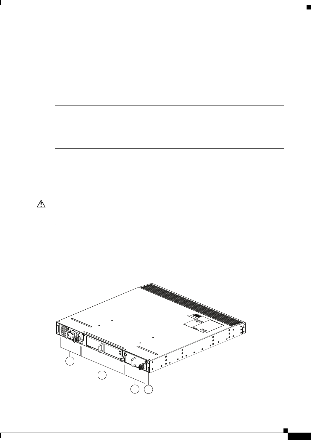
3-21
Cisco Nexus 2000 Series Hardware Installation Guide
Chapter 3 Using a Fabric Extender with a Cisco Nexus 9000 Series Switch
Cisco Nexus 2232PP FEX
Cisco Nexus 2232PP FEX
The Cisco Nexus 2232PP FEX (N2K-C2248PP) is a stackable 1-RU FEX that has 32 1- and 10-Gigabit
Ethernet host interfaces (downlink ports for SFP and SFP+ transceivers) and eight 10-Gigabit Ethernet
and Fibre Channel over Ethernet (FCoE) fabric interfaces (uplink ports for SFP+ transceivers). This FEX
requires a 19-inch (48.26 cm) rack for its installation. Table 3-7 lists its physical characteristics.
You can order the Cisco Nexus 2232PP with front-to-back (port-side exhaust) or back-to-front (port-side
intake) airflow and with AC or DC power supplies. If you are going to install the port side in a hot aisle,
then order port-side-exhaust airflow for the fan trays and power supplies. If you are going to install the
port side in the cold aisle, order port-side-intake airflow for the fan trays and power supplies.
Caution Make sure that all of the fan tray and power supply modules use the same airflow direction and have the
same color designation on the front. Otherwise, the switch can over heat and shut down,
The front of the Cisco Nexus 2232PP FEX chassis has one or two power supplies, a fan tray, and two
LEDs as shown in Figure 3-21. This FEX model requires one power supply, but if you want power
redundancy, you must install a second power supply.
Figure 3-21 Front View of the Cisco Nexus 2232PP Chassis
Table 3-7 Physical Characteristics for the Cisco Nexus 2232PP FEX
Dimensions
Width
Depth
Height
17.3 inches (43.94 cm)
17.7 inches (44.96 cm)
1.72 inches (4.37 cm)
Weight118.3 lb (8.3 kg)
1. Measured with two power supplies and one fan module installed
2
1
34
239279
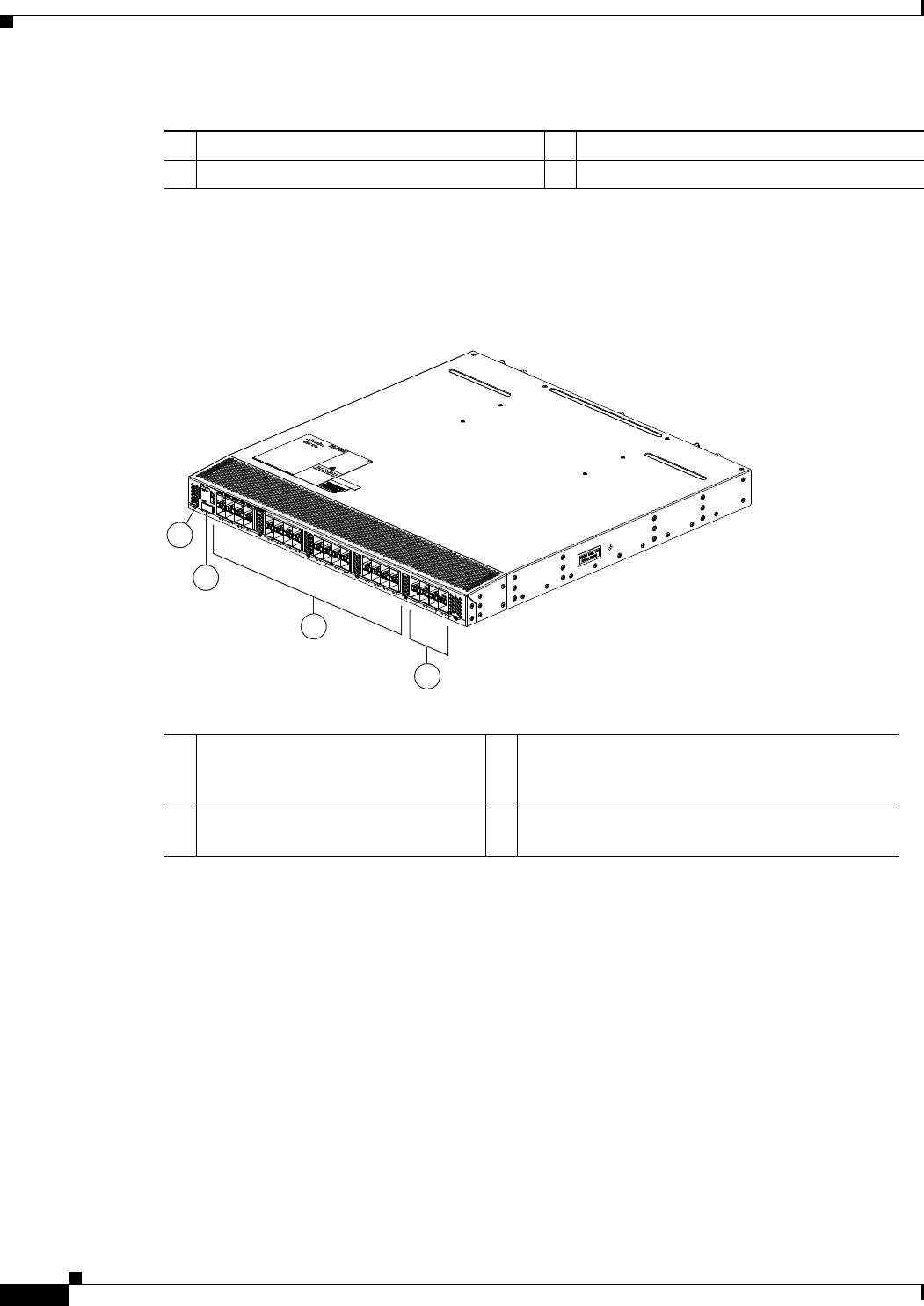
3-22
Cisco Nexus 2000 Series Hardware Installation Guide
Chapter 3 Using a Fabric Extender with a Cisco Nexus 9000 Series Switch
Cisco Nexus 2232PP FEX
The rear of the Cisco Nexus 2232PP FEX has 32 1- and 10-Gigabit Ethernet downlink SFP or SFP+
ports, eight 10-Gigabit Ethernet uplink SFP+ or FET ports, an HDMI port, and two LEDs, as shown in
Figure 3-22.
Figure 3-22 Rear View of the Cisco Nexus 2232PP Chassis
For LED descriptions, see Appendix E, “LEDs.”
This section includes the following topics:
•Ports for the Cisco Nexus 2232PP FEX, page 3-22
•Power Supplies for the Cisco Nexus 2232PP FEX, page 3-23
•Fan Tray for the Cisco Nexus 2232PP FEX, page 3-23
•Transceivers Supported by the Cisco Nexus 2232PP FEX, page 3-24
Ports for the Cisco Nexus 2232PP FEX
The downlink and uplink ports are numbered from top to bottom and then from left to right as shown in
Figure 3-23.
1Power supply 3Power supply (blank shown)
2Fan tray 4Status (top) and ID (bottom) LEDs
3
2
4
239278
1
1Status (top) and ID (bottom) LEDs 31- and 10-Gigabit Ethernet host ports
(copper/optical downlink ports for SFP or SFP+
transceivers) (48)
2HDMI port 410-Gigabit Ethernet fabric ports (copper/optical
uplink ports for SFP+ or FET transceivers) (4)
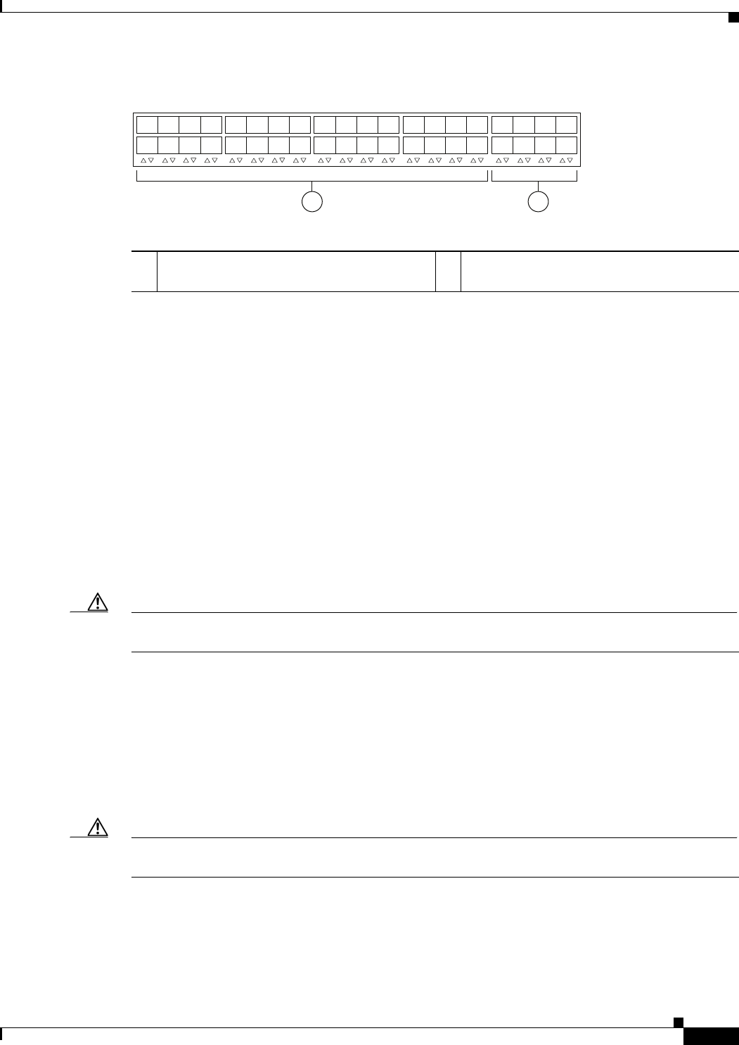
3-23
Cisco Nexus 2000 Series Hardware Installation Guide
Chapter 3 Using a Fabric Extender with a Cisco Nexus 9000 Series Switch
Cisco Nexus 2232PP FEX
Figure 3-23 Port Numbering on the Cisco Nexus 2232PP FEX
For information about the transceivers and connectors that you can use with these ports, see the
“Transceivers Supported by the Cisco Nexus 2232PP FEX” section on page 3-24.
Power Supplies for the Cisco Nexus 2232PP FEX
The Cisco Nexus 2200 Platform FEX chassis have two slots for front-end AC or DC power supplies that
have port-side-exhaust or port-side-intake airflow. These chassis are fully functional with one power
supply, but you can install a second power supply for power redundancy. You can install any of the
following power supplies in those two bays:
•AC power supply with port-side-exhaust airflow (N2200-PAC-400W)
•AC power supply with port-side-intake airflow (N2200-PAC-400W-B)
•DC power supply with port-side-exhaust airflow (N2200-PDC-400W)
•DC power supply with port-side-intake airflow (N2200-PDC-350W-B)
Caution Make sure that all of the fan tray and power supply modules use the same airflow direction and have the
same color designation on the front. Otherwise, the switch can over heat and shut down,
For information on these power supplies, see the “Power Supplies for the Cisco Nexus 2248TP FEX”
section on page 3-13 and the power supply specifications in the Appendix B, “Technical Specifications”.
Fan Tray for the Cisco Nexus 2232PP FEX
The Cisco Nexus 2232PP and 2232TM FEX use the same fan tray, which you can order with either
port-side-exhaust airflow (N2K-C2232-FAN) or port-side-intake airflow (N2K-C2232-FAN-B).
Caution Make sure that all of the fan tray and power supply modules use the same airflow direction and have the
same color designation on the front. Otherwise, the switch can over heat and shut down,
For more information on this fan tray, see the “Fan Tray for the Cisco Nexus 2232TM FEX” section on
page 3-18 and the fan tray specifications in Appendix B, “Technical Specifications”. For LED
descriptions, see Appendix E, “LEDs”.
12
330042
1
2
3
4
5
6
7
8
1
2
3
4
5
6
7
8
911
14
13 15
12
10 16
17
18
19
20
21 23
22
24
25
26
27
28
29 31
30 32
11- and 10-Gigabit Ethernet downlink ports,
numbered 1 through 32
210-Gigabit Ethernet uplink ports, numbered 1
through 8

3-24
Cisco Nexus 2000 Series Hardware Installation Guide
Chapter 3 Using a Fabric Extender with a Cisco Nexus 9000 Series Switch
Cisco Nexus 2232PP FEX
Transceivers Supported by the Cisco Nexus 2232PP FEX
The Cisco Nexus 2232PP FEX supports copper or optical SFP and SFP+ transceivers for up to 32 host
downlink connections and optical FEX Transceivers (FETs) and SFP+ transceivers for up to eight fabric
uplink connections, as specified in the following table.
Table 3-8 Supported Transceivers and Connector for the Cisco Nexus 2232PP FEX Interfaces
Transceiver or Connector
Cable
Type
Fabric
Interface
(Uplink)
Host
Interface
(Downlink) Comments
FET-10G Optical X – 10-Gbps FEX transceiver
GLC-LH-SM Optical X 1-Gbps
GLC-SX-MM Optical X 1-Gbps
GLC-T Copper X 1-Gbps
SFP-GE-L Optical X 1-Gbps
SFP-GE-S Optical X 1-Gbps
SFP-GE-T Copper X 1-Gbps
SFP-10G-LR Optical X X 10-Gbps long range transceiver (up to 6.2 miles [10 km])
SFP-10G-SR Optical X X 10-Gbps Short range transceiver (up to 984 feet [300 m])
SFP -H10GB-CU1M Copper X X 10-Gbps Twinax, passive transceiver (3.3 feet [1 meter])
SFP -H10GB-CU3M Copper X X 10-Gbps Twinax, passive transceiver (9.8 feet [3 meters)
SFP -H10GB-CU5M Copper X X 10-Gbps Twinax, passive transceiver (16.4 feet [5 meters])
SFP -H10GB-ACU7M Copper X X 10-Gbps Twinax, active transceiver (23.0 feet [7 meters])
SFP -H10GB-ACU10M Copper X X 10-Gbps Twinax, active transceiver (32.8 feet [10 meters])
SFP-10G-AOC1M Optical X X 10-Gbps active optical cable (3.3 feet [1 meter])
SFP-10G-AOC2M Optical X X 10-Gbps active optical cable (6.6 feet [2 meters])
SFP-10G-AOC3M Optical X X 10-Gbps active optical cable (9.8 feet [3 meters])
SFP-10G-AOC5M Optical X X 10-Gbps active optical cable (16.4 feet [5 meters])
SFP-10G-AOC7M Optical X X 10-Gbps active optical cable (23.0 feet [7 meters])
SFP-10G-AOC10M Optical X X 10-Gbps active optical cable (32.8 feet [10 meters])
QSFP-4X10G-AOC1M Optical X – 40- and 10-Gbps active optical breakout cable (3.3 feet
[1 meter])
QSFP-4X10G-AOC2M Optical X – 40- and 10-Gbps active optical breakout cable (6.6 feet
[2 meters])
QSFP-4X10G-AOC3M Optical X – 40- and 10-Gbps active optical breakout cable (9.8 feet
[3 meters])
QSFP-4X10G-AOC5M Optical X – 40- and 10-Gbps active optical breakout cable (16.4 feet
[5 meters])
QSFP-4X10G-AOC7M Optical X – 40- and 10-Gbps active optical breakout cable (23.0 feet
[7 meters])
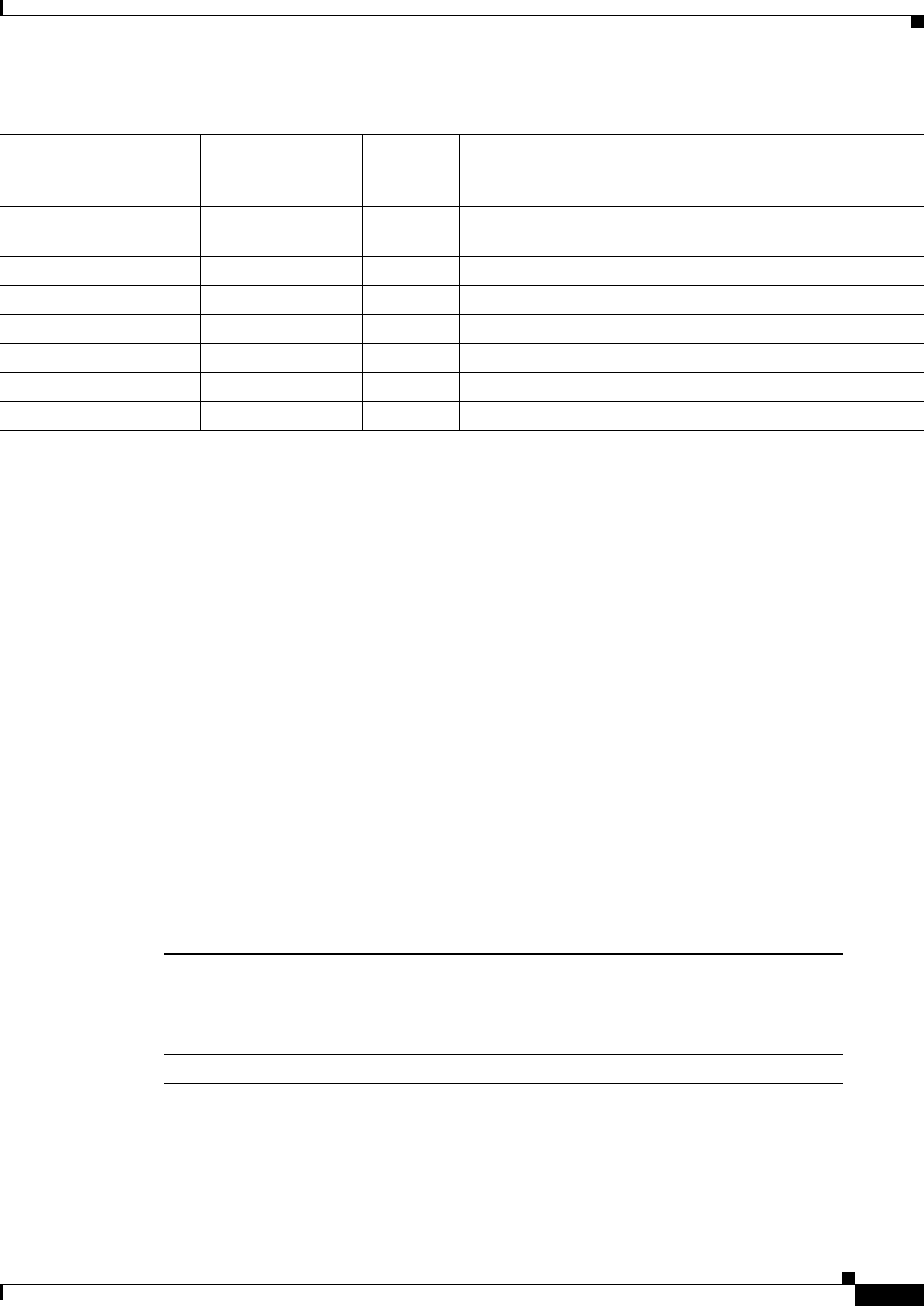
3-25
Cisco Nexus 2000 Series Hardware Installation Guide
Chapter 3 Using a Fabric Extender with a Cisco Nexus 9000 Series Switch
Cisco Nexus 2224TP FEX
For more information on the transceivers that you can use with this FEX, see the Cisco Transceiver
Modules Compatibility Information at
http://www.cisco.com/c/en/us/support/interfaces-modules/transceiver-modules/products-device-suppor
t-tables-list.html.
Figure 3-10 on page 3-9 shows the major features of the SFP+ optical transceiver used for uplink
connections.
Figure 3-11 on page 3-10 shows the major features of the SFP+ copper transceiver and cable used for
uplink connections.
Figure 3-12 on page 3-10 shows the major features of RJ-45 connectors, which are used for the downlink
connections.
Cisco Nexus 2224TP FEX
The Cisco Nexus 2224TP FEX is a stackable, 1-RU FEX that has 24 100/1000 Ethernet host interfaces
(100/1000BASE-T downlink ports for RJ-45 connectors) and two 10-Gigabit Ethernet fabric interfaces
(copper/optical uplink ports for SFP+ transceivers). It requires a 19-inch (48.26 cm) rack for its
installation. Table 3-9 lists its physical characteristics.
You can order the Cisco Nexus 2224TP FEX with front-to-back (port-side exhaust) or port-side-intake
(port-side intake) airflow and with AC or DC power supplies. If you are going to install the port side in
a hot aisle, then order port-side-exhaust airflow for the fan trays and power supplies. If you are going to
install the port side in the cold aisle, order port-side-intake airflow for the fan trays and power supplies.
QSFP-4X10G-AOC10M Optical X – 40- and 10-Gbps active optical breakout cable (32.8 feet
[10 meters])
QSFP-4SFP10G-CU1M Optical X – 40- and 10-Gbps copper breakout cable (3.3 feet [1 meter])
QSFP-4SFP10G-CU3M Optical X – 40- and 10-Gbps copper breakout cable (9.8 feet [3 meters])
QSFP-4SFP10G-CU5M Optical X – 40- and 10-Gbps copper breakout cable (16.4 feet [5 meters])
QSFP-4SFP10G-CU7M Optical X – 40- and 10-Gbps copper breakout cable (23.0 feet [7 meters])
QSFP-4SFP10G-CU10M Optical X – 40- and 10-Gbps copper breakout cable (32.8 feet [10 meters])
RJ-45 Copper – X 100/1000 Mbps Connector
Table 3-8 Supported Transceivers and Connector for the Cisco Nexus 2232PP FEX Interfaces
Transceiver or Connector
Cable
Type
Fabric
Interface
(Uplink)
Host
Interface
(Downlink) Comments
Table 3-9 Physical Characteristics for the Cisco Nexus 2224TP FEX
Dimensions
Width
Depth
Height
17.3 inches (43.94 cm)
17.7 inches (44.96 cm)
1.72 inches (4.37 cm)
Weight116.6 lb (7.53 kg)
1. Measured with two power supplies and one fan module installed.
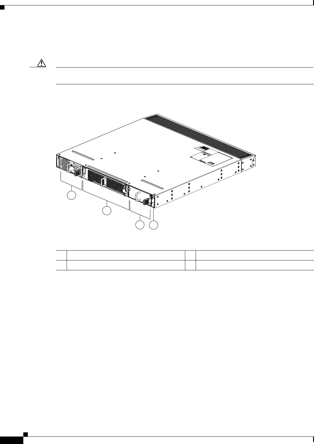
3-26
Cisco Nexus 2000 Series Hardware Installation Guide
Chapter 3 Using a Fabric Extender with a Cisco Nexus 9000 Series Switch
Cisco Nexus 2224TP FEX
The front of the Cisco Nexus 2224TP FEX chassis has one or two power supplies, a fan tray, and two
LEDs as shown in Figure 3-24. This FEX model requires one power supply, but if you want power
redundancy, you must install a second power supply.
Caution Make sure that all of the fan tray and power supply modules use the same airflow direction and have the
same color designation on the front. Otherwise, the switch can over heat and shut down,
Figure 3-24 Front View of the Cisco Nexus 2224TP Chassis
The rear of the Cisco Nexus 2224TP FEX has 24 100/1000BASE-T Ethernet downlink ports, two
10-Gigabit Ethernet uplink ports, an HDMI port, and LEDs, as shown in Figure 3-25.
2
1
34
239281
1Power supply 3Power supply (blank shown)
2Fan tray 4Status (top) and ID (bottom) LEDs
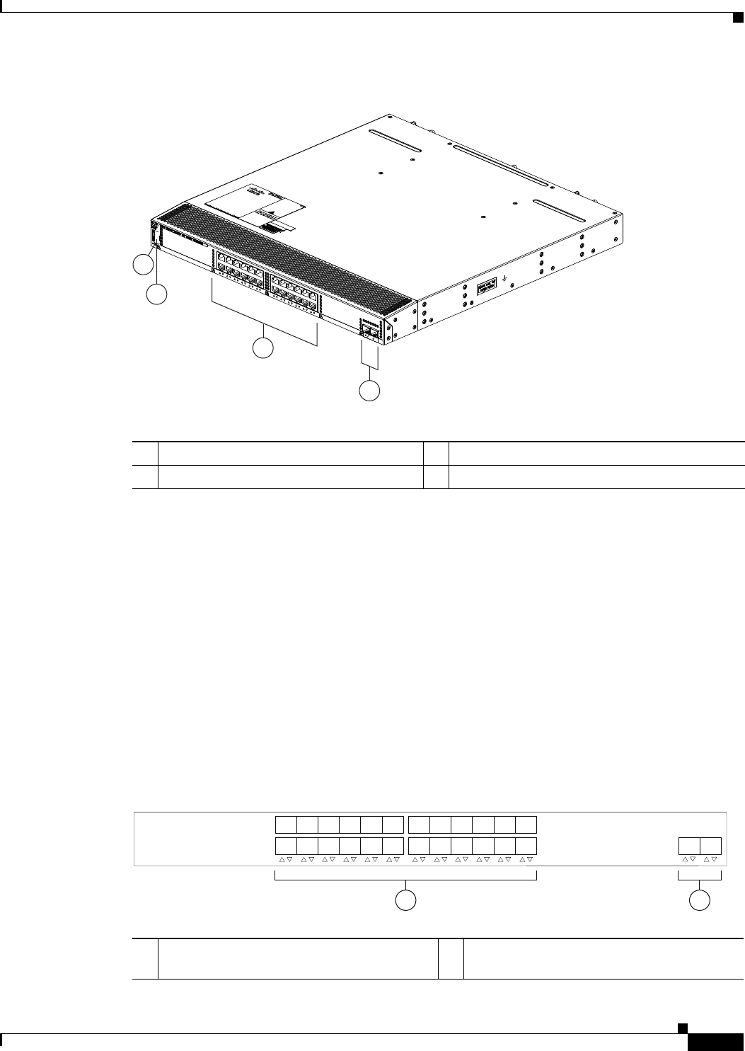
3-27
Cisco Nexus 2000 Series Hardware Installation Guide
Chapter 3 Using a Fabric Extender with a Cisco Nexus 9000 Series Switch
Cisco Nexus 2224TP FEX
Figure 3-25 Rear View of the Cisco Nexus 2224TP Chassis
For LED descriptions, see Appendix E, “LEDs.”
This section includes the following topics:
•Ports for the Cisco Nexus 2224TP FEX, page 3-27
•Power Supplies for the Cisco Nexus 2224TP FEX, page 3-28
•Fan Tray for the Cisco Nexus 2224TP FEX, page 3-28
•Transceivers and Connectors Supported by the Cisco Nexus 2224TP FEX, page 3-28
Ports for the Cisco Nexus 2224TP FEX
The downlink and uplink ports are numbered from top to bottom and then from left to right as shown in
Figure 3-26.
Figure 3-26 Port Numbering on the Cisco Nexus 2224TP FEX
3
4
239280
2
1
1Status (top) and ID (bottom) LEDs 3100/1000BASE-T Ethernet downlink ports (24)
2HDMI port 410-Gigabit Ethernet uplink ports (2)
1 2
330046
1
2
3
4
5
6
7
8
9
10
11
12
13
14
15
16
17
18
19
20
21
22
23
24 12
11- and 10-Gigabit Ethernet downlink ports,
numbered 1 through 24
210-Gigabit Ethernet uplink ports, numbered 1
through 2
3-28
Cisco Nexus 2000 Series Hardware Installation Guide
Chapter 3 Using a Fabric Extender with a Cisco Nexus 9000 Series Switch
Cisco Nexus 2224TP FEX
For information about the transceivers and connectors that you can use with these ports, see the
“Transceivers and Connectors Supported by the Cisco Nexus 2224TP FEX” section on page 3-28.
Power Supplies for the Cisco Nexus 2224TP FEX
The Cisco Nexus 2200 Platform FEX chassis have two slots for front-end AC or DC power supplies that
have port-side-exhaust or port-side-intake airflow. These chassis are fully functional with one power
supply, but you can install a second power supply for power redundancy. You can install any of the
following power supplies in those two bays:
•AC power supply with port-side-exhaust airflow (N2200-PAC-400W)
•AC power supply with port-side-intake airflow (N2200-PAC-400W-B)
•DC power supply with port-side-exhaust airflow (N2200-PDC-400W)
•DC power supply with port-side-intake airflow (N2200-PDC-350W-B)
Caution Make sure that all of the fan tray and power supply modules use the same airflow direction and have the
same color designation on the front. Otherwise, the switch can over heat and shut down,
For information on these power supplies, see the “Power Supplies for the Cisco Nexus 2248TP FEX”
section on page 3-13 and the power supply specifications in the Appendix B, “Technical Specifications”.
Fan Tray for the Cisco Nexus 2224TP FEX
The Cisco Nexus 2224TP, 2248TP, and 2248TP-E FEXs use the same fan tray that you can order with
either port-side-exhaust airflow (N2K-C2248-FAN) or port-side-intake airflow (N2K-C2248-FAN-B).
For information on this fan tray, see the “Fan Tray for the Cisco Nexus 2248TP FEX” section on
page 3-13 and the fan tray specifications in Appendix B, “Technical Specifications”. For LED
descriptions, see Appendix E, “LEDs”. To replace one of these fan trays, see “Removing and Installing
the Fan Tray” section on page 4-21.
Transceivers and Connectors Supported by the Cisco Nexus 2224TP FEX
The Cisco Nexus 2224TP FEX supports SFP+ Ethernet optical and copper transceivers and optical FEX
Transceivers (FETs) for up to two fabric uplink connections to Cisco Nexus 9396PX switches, and it
supports RJ-45 connectors for up to 24 downlink connections to hosts. Table 3-2 lists the transceivers
supported by this FEX for its uplink and downlink connections.
Table 3-10 Supported Transceivers and Connector for the Cisco Nexus 2224TP FEX Interfaces
Transceiver or Connector
Cable
Type
Fabric
Interface
(Uplink)
Host
Interface
(Downlink) Comments
FET-10G Optical X – 10-Gbps FEX transceiver
SFP-10G-LR Optical X – 10-Gbps long range transceiver (up to 6.2 miles [10 km])
SFP-10G-SR Optical X – 10-Gbps Short range transceiver (up to 984 feet [300 m])

3-29
Cisco Nexus 2000 Series Hardware Installation Guide
Chapter 3 Using a Fabric Extender with a Cisco Nexus 9000 Series Switch
Cisco Nexus 2224TP FEX
For more information on the transceivers that you can use with this FEX, see the Cisco Transceiver
Modules Compatibility Information at
http://www.cisco.com/c/en/us/support/interfaces-modules/transceiver-modules/products-device-suppor
t-tables-list.html.
Figure 3-10 on page 3-9 shows the SFP+ optical transceiver used for uplink connections.
Figure 3-11 on page 3-10 identifies the major features of the SFP+ copper transceiver and cable used for
uplink connections.
SFP -H10GB-CU1M Copper X – 10-Gbps Twinax, passive transceiver (3.3 feet [1 meter])
SFP -H10GB-CU3M Copper X – 10-Gbps Twinax, passive transceiver (9.8 feet [3 meters)
SFP -H10GB-CU5M Copper X – 10-Gbps Twinax, passive transceiver (16.4 feet [5 meters])
SFP -H10GB-ACU7M Copper X – 10-Gbps Twinax, active transceiver (23.0 feet [7 meters])
SFP -H10GB-ACU10M Copper X – 10-Gbps Twinax, active transceiver (32.8 feet [10 meters])
SFP-10G-AOC1M Optical X – 10-Gbps active optical cable (3.3 feet [1 meter])
SFP-10G-AOC2M Optical X – 10-Gbps active optical cable (6.6 feet [2 meters])
SFP-10G-AOC3M Optical X – 10-Gbps active optical cable (9.8 feet [3 meters])
SFP-10G-AOC5M Optical X – 10-Gbps active optical cable (16.4 feet [5 meters])
SFP-10G-AOC7M Optical X – 10-Gbps active optical cable (23.0 feet [7 meters])
SFP-10G-AOC10M Optical X – 10-Gbps active optical cable (32.8 feet [10 meters])
QSFP-4X10G-AOC1M Optical X – 40- and 10-Gbps active optical breakout cable (3.3 feet
[1 meter])
QSFP-4X10G-AOC2M Optical X – 40- and 10-Gbps active optical breakout cable (6.6 feet
[2 meters])
QSFP-4X10G-AOC3M Optical X – 40- and 10-Gbps active optical breakout cable (9.8 feet
[3 meters])
QSFP-4X10G-AOC5M Optical X – 40- and 10-Gbps active optical breakout cable (16.4 feet
[5 meters])
QSFP-4X10G-AOC7M Optical X – 40- and 10-Gbps active optical breakout cable (23.0 feet
[7 meters])
QSFP-4X10G-AOC10M Optical X – 40- and 10-Gbps active optical breakout cable (32.8 feet
[10 meters])
QSFP-4SFP10G-CU1M Optical X – 40- and 10-Gbps copper breakout cable (3.3 feet [1 meter])
QSFP-4SFP10G-CU3M Optical X – 40- and 10-Gbps copper breakout cable (9.8 feet [3 meters])
QSFP-4SFP10G-CU5M Optical X – 40- and 10-Gbps copper breakout cable (16.4 feet [5 meters])
QSFP-4SFP10G-CU7M Optical X – 40- and 10-Gbps copper breakout cable (23.0 feet [7 meters])
QSFP-4SFP10G-CU10M Optical X – 40- and 10-Gbps copper breakout cable (32.8 feet [10 meters])
RJ-45 Copper – X 100/1000 Mbps Connector
Table 3-10 Supported Transceivers and Connector for the Cisco Nexus 2224TP FEX Interfaces
Transceiver or Connector
Cable
Type
Fabric
Interface
(Uplink)
Host
Interface
(Downlink) Comments


CHAPTER
4-1
Cisco Nexus 2000 Series Hardware Installation Guide
4
Installing a Cisco Nexus Fabric Extender
This chapter describes how to install the Cisco Nexus Fabric Extenders (FEXs) and includes the
following sections:
•Preparing for Installation, page 4-2
•Installing the Cisco Nexus Fabric Extender Chassis in a Cabinet or Rack, page 4-6
•Grounding the System, page 4-7
•Grounding the Chassis, page 4-14
•Starting the Cisco Nexus Fabric Extender, page 4-14
•Removing and Installing Components, page 4-16
•Repacking the Cisco Nexus Fabric Extender for Return Shipment, page 4-23
Note Before you install, operate, or service the system, read the Regulatory Compliance and Safety
Information for important safety information.
Warning
IMPORTANT SAFETY INSTRUCTIONS
This warning symbol means danger. You are in a situation that could cause bodily injury. Before you
work on any equipment, be aware of the hazards involved with electrical circuitry and be familiar
with standard practices for preventing accidents. Use the statement number provided at the end of
each warning to locate its translation in the translated safety warnings that accompanied this device.
Statement 1071
Warning
This unit is intended for installation in restricted access areas. A restricted access area can be
accessed only through the use of a special tool, lock and key, or other means of security.
Statement 1017
Warning
Only trained and qualified personnel must be allowed to install, replace, or service this equipment.
Statement 1030

4-2
Cisco Nexus 2000 Series Hardware Installation Guide
Chapter 4 Installing a Cisco Nexus Fabric Extender
Preparing for Installation
Preparing for Installation
This section includes the following topics:
•Installation Options, page 4-2
•Airflow Considerations, page 4-2
•Chassis Weight, page 4-3
•Installation Guidelines, page 4-3
•Required Tools and Equipment, page 4-4
•Unpacking and Inspecting the Cisco Nexus Fabric Extender, page 4-5
Installation Options
The Cisco Nexus FEX can be installed using the following methods:
•In an open EIA rack, using the following items:
–
The rack-mount kit shipped with the device
–
The EIA Shelf Bracket Kit (an optional kit, purchased separately)
•In a perforated or solid-walled EIA cabinet, using one of the following:
–
The rack-mount kit shipped with the device
–
The EIA Shelf Bracket Kit (an optional kit, purchased separately)
For instructions on installing the device using the rack-mount kit shipped with the device, see the
“Installing the Cisco Nexus Fabric Extender Chassis in a Cabinet or Rack” section on page 4-6.
Note The optional EIA Shelf Bracket Kit is not provided with the device. To order the kit, contact your device
provider.
Airflow Considerations
Airflow through the Cisco Nexus FEX is from the port side exhaust to the back or the back to the port
side exhaust. To ensure proper airflow, follow these guidelines:
•Position the chassis so that its air intake side (port side exhaust side for port side exhaust airflow or
back side for port side intake airflow) is in a cold aisle. Otherwise, an overtemperature condition can
occur and the system can shut down.
•Avoid having the air intake where other systems exhaust air.
•Due to the shallow depth of the Cisco Nexus FEX, it is also possible for air to recirculate across the
top and bottom of the chassis in a partially populated rack.
•Make sure that the fan tray and power supply modules all use the same direction of airflow. All of
the modules should have no black stripe (port side exhaust airflow) or all of the modules should have
a black stripe (port side intake airflow).

4-3
Cisco Nexus 2000 Series Hardware Installation Guide
Chapter 4 Installing a Cisco Nexus Fabric Extender
Preparing for Installation
Note If the switch is powered up with modules that have different airflow directions, you need to shut
down the switch before replacing the modules with the wrong airflow direction.
•Maintain ambient airflow throughout the data center to ensure normal operation.
•Consider the heat dissipation of all equipment when determining air-conditioning requirements.
When evaluating airflow requirements, take into consideration that hot air generated by equipment
at the bottom of the rack can be drawn in the intake ports of the equipment above.
•If you mount a chimney type of rack, avoid mounting it in a way that is contrary to the direction of
flow in the chimney, where the chimney overpowers the system fans.
Chassis Weight
When lifting the system, follow these guidelines:
•Disconnect all power and external cables before lifting the system.
•Have two people lift the system. The Cisco Nexus FEXs can weigh up to 18.5 pounds (8.4 kg).
•Ensure that your footing is solid and the weight of the system is evenly distributed between your
feet.
•Lift the system slowly, keeping your back straight. Lift with your legs, not with your back. Bend at
the knees, not at the waist.
Installation Guidelines
When installing the Cisco Nexus FEX, follow these guidelines:
•Plan your site configuration and prepare the site before installing the chassis. Appendix G, “Site
Preparation and Maintenance Records,” lists the recommended site planning tasks.
•Record the information listed in Appendix G, “Site Preparation and Maintenance Records,” as you
install and configure the device.
•Ensure that there is adequate space around the device to allow for servicing the device and for
adequate airflow (Appendix B, “Technical Specifications,” lists airflow requirements).
•Ensure that the air-conditioning meets the heat dissipation requirements listed in Appendix B,
“Technical Specifications,”
•Ensure that the chassis air intake will be located in a cold aisle and away from the exhaust of other
systems.
•Ensure that all of the fan tray and power supply modules have the same direction of airflow as
follows (the switch supports only one airflow direction for all modules):
–
Port-side intake airflow modules have black stripes.
–
Port-side exhaust airflow modules have no colored stripes.
Note If the switch is powered up with modules that have different airflow directions, you need to shut
down the switch before replacing the modules with the wrong airflow direction.

4-4
Cisco Nexus 2000 Series Hardware Installation Guide
Chapter 4 Installing a Cisco Nexus Fabric Extender
Preparing for Installation
•Ensure that the cabinet or rack meets the requirements listed in Appendix A, “Cabinet and Rack
Installation.”
Note Jumper power cords are available for use in a cabinet. See the “Jumper Power Cord” section on
page C-8.
•Ensure that the chassis is adequately grounded. If the device is not mounted in a grounded rack, we
recommend connecting both the system ground on the chassis and the power supply ground to an
earth ground.
•Ensure that the site power meets the power requirements listed in Appendix B, “Technical
Specifications,” If available, you can use an uninterrupted power supply (UPS) to protect against
power failures.
Caution Avoid UPS types that use ferroresonant technology. These UPS types can become unstable
with systems such as the Cisco Nexus FEX, which can have substantial current draw
fluctuations because of fluctuating data traffic patterns.
•Ensure that circuits are sized according to local and national codes. For North America, the power
supply requires a 15-A or 20-A circuit.
Caution To prevent loss of input power, ensure the total maximum loads on the circuits supplying
power to the device are within the current ratings for the wiring and breakers.
•Use the following screw torques when installing the device:
–
Captive screws: 4 in-lb
–
M3 screws: 4 in-lb
–
M4 screws: 12 in-lb
–
10-32 screws: 20 in-lb
–
12-24 screws: 30 in-lb
Required Tools and Equipment
Before beginning the installation, ensure that the following items are ready:
•Number 1 and number 2 Phillips screwdrivers with torque capability
•3/16-inches flat-blade screwdriver
•Tape measure and level
•ESD wrist strap or other grounding device
•Antistatic mat or antistatic foam
The following additional items (not found in the accessory kit) are required to ground the chassis:
•Grounding cable (6 AWG recommended), sized according to local and national installation
requirements; the required length depends on the proximity of the Cisco Nexus FEX to proper
grounding facilities
•Crimping tool large enough to accommodate girth of lug

4-5
Cisco Nexus 2000 Series Hardware Installation Guide
Chapter 4 Installing a Cisco Nexus Fabric Extender
Preparing for Installation
•Wire-stripping tool
Unpacking and Inspecting the Cisco Nexus Fabric Extender
Caution When handling device components, wear an ESD wrist strap and handle modules by the carrier edges
only. An ESD socket is provided on the chassis. For the ESD socket to be effective, the chassis must be
grounded through the power cable, the chassis ground, or the metal-to-metal contact with a grounded
rack.
Tip Keep the shipping container in case the chassis requires shipping in the future.
Note The device is thoroughly inspected before shipment. If any damage occurred during transportation or
any items are missing, contact your customer service representative immediately.
To inspect the shipment, follow these steps:
Step 1 Compare the shipment to the equipment list provided by your customer service representative and verify
that you have received all items, including the following:
•Print documentation
•Grounding lug kit
•Rack-mount kit
•ESD wrist strap
•Cables with connectors
•Any optional items ordered
Step 2 Check for damage and report any discrepancies or damage to your customer service representative. Have
the following information ready:
•Invoice number of shipper (see packing slip)
•Model and serial number of the damaged unit
•Description of damage
•Effect of damage on the installation
Step 3 Make sure that the fan tray and power supplies all use the same direction of airflow.
•Port-side exhaust airflow modules do not have a black stripe across the front of the module.
•Port-side intake airflow modules have a black stripe across the front of the module.
4-6
Cisco Nexus 2000 Series Hardware Installation Guide
Chapter 4 Installing a Cisco Nexus Fabric Extender
Installing the Cisco Nexus Fabric Extender Chassis in a Cabinet or Rack
Installing the Cisco Nexus Fabric Extender Chassis in a Cabinet
or Rack
This section describes how to use the rack-mount kit provided with the device to install the Cisco Nexus
Fabric Extender into a cabinet or rack that meets the requirements described in Appendix A, “Cabinet
and Rack Installation.”
Caution If the rack is on wheels, ensure that the brakes are engaged or that the rack is otherwise stabilized.
Table 4-1 lists the items contained in the rack-mount kit provided with the device.
Table 4-1 lists the items contained in the rack-mount kit provided with the device.
Table 4-1 Cisco Nexus 2000 Series FEX Rack-Mount Kit
Quantity Part Description
2 Rack-mount brackets
12 M4x0.7 x 8-mm Phillips countersunk screws
2 Rack-mount guides
10 10-32 rack nuts
10 10-32 x 3/4-inch Phillips pan head screws
2 Slider rails
Table 4-2 Cisco Nexus 2300 Series FEX Rack-Mount Kit
Quantity Part Description
2 Rack-mount brackets
2 M4 8-mm Phillips pan head screws
2 Rack-mount guides
10 M4 x 0.7 x 7 mm rack nuts
10 10-32 x 3/4-inch Phillips pan head screws
2 Slider rails

4-7
Cisco Nexus 2000 Series Hardware Installation Guide
Chapter 4 Installing a Cisco Nexus Fabric Extender
Grounding the System
To install the device in a cabinet or rack using the rack-mount kit provided with the device, follow these
steps:
Step 1 Install the front rack-mount brackets as follows:
a. Position a front rack-mount bracket against the chassis and align the screw holes. Attach the front
rack-mount bracket to the chassis with six of the M4 screws.
b. Repeat with the other front rack-mount bracket on the other side of the device.
Step 2 Install the rack-mount guides on the device as follows:
a. Position one of the rack-mount brackets against the side of the device and align the screw holes.
Attach the bracket to the device with two of the flat-head M4 screws.
b. Repeat with the other rack-mount bracket on the other side of the device.
Step 3 Attach the slider rails to the rack. Use two 12-24 screws or two 10-32 screws, depending on the rack rail
thread type. For racks with square holes, insert the 12-24 cage nuts in position behind the mounting holes
in the slider rails.
a. Repeat with the other slider rail on the other side of the rack.
b. Use the tape measure and level to verify that the rails are horizontal and at the same height.
Step 4 Insert the device into the rack as follows:
a. Using both hands, position the device with the back of the device between the port side exhaust posts
of the rack.
b. Align the two rack-mount guides on either side of the device with the slider rails installed in the
rack. Slide the rack-mount glides onto the slider rails, and then gently slide the device all the way
into the rack. If the device does not slide easily, try realigning the rack-mount glides on the slider
rails.
Step 5 Stabilize the device in the rack by attaching the front rack-mount brackets to the front rack-mounting
rails as follows:
a. Insert two screws (12-24 or 10-32, depending on the rack type) through the cage nuts and the holes
in one of the front rack-mount brackets and into the threaded holes in the rack-mounting rail.
b. Repeat for the front rack-mount bracket on the other side of the device.
Grounding the System
This section describes the need for system grounding and explains how to prevent damage from
electrostatic discharge.
This section includes the following topics:
•Proper Grounding Guidelines, page 4-8
•Preventing Electrostatic Discharge Damage, page 4-9
•Establishing the System Ground, page 4-13
•Required Tools and Equipment, page 4-13

4-8
Cisco Nexus 2000 Series Hardware Installation Guide
Chapter 4 Installing a Cisco Nexus Fabric Extender
Grounding the System
Proper Grounding Guidelines
Grounding is one of the most important parts of equipment installation. Proper grounding practices
ensure that the buildings and the installed equipment within them have low-impedance connections and
low-voltage differentials between chassis. When you properly ground systems during installation, you
reduce or prevent shock hazards, equipment damage due to transients, and data corruption. Table 4-3
lists some general grounding practice guidelines.
Table 4-3 Proper Grounding Guidelines
Environment
Electromagnetic Noise Severity
Level Grounding Recommendations
Commercial building is
subjected to direct lightning
strikes.
For example, some places in the
United States, such as Florida,
are subject to more lightning
strikes than other areas.
High All lightning protection devices
must be installed in strict
accordance with manufacturer
recommendations. Conductors
carrying lightning current
should be spaced away from
power and data lines in
accordance with applicable
recommendations and codes.
Best grounding
recommendations must be
closely followed.
Commercial building is located
in an area where lightning
storms frequently occur but is
not subject to direct lightning
strikes.
High Grounding recommendations
must be closely followed.
Commercial building contains a
mix of information technology
equipment and industrial
equipment, such as welding.
Medium to high Grounding recommendations
must be closely followed.
Existing commercial building is
not subject to natural
environmental noise or
man-made industrial noise. This
building contains a standard
office environment. This
installation has a history of
malfunction due to
electromagnetic noise.
Medium Determine source and cause of
noise if possible, and mitigate as
closely as possible at the noise
source or reduce coupling from
the noise source to the affected
equipment. Grounding
recommendations must be
closely followed.

4-9
Cisco Nexus 2000 Series Hardware Installation Guide
Chapter 4 Installing a Cisco Nexus Fabric Extender
Grounding the System
Note In all situations, grounding practices must comply with local National Electric Code (NEC)
requirements or local laws and regulations.
Note Always ensure that all of the devices are completely installed and that the captive installation screws are
fully tightened. In addition, ensure that all I/O cables and power cords are properly seated. These
practices are normal installation practices and must be followed in all installations.
Preventing Electrostatic Discharge Damage
Electrostatic discharge (ESD) damage, which can occur when modules or other Field Replaceable Units
(FRUs) are improperly handled, results in intermittent or complete failures. Devices consist of printed
circuit boards that are fixed in metal carriers. Electromagnetic interference (EMI) shielding and
connectors are integral components of the carrier. Although the metal carrier helps to protect the board
from ESD, always use an ESD grounding strap when handling modules.
For preventing ESD damage, follow these guidelines:
•Always use an ESD wrist strap and ensure that it makes maximum contact with bare skin.
•ESD grounding straps are available with banana plugs, metal spring clips, or alligator clips. All
Cisco Nexus 2000 Series FEX chassis are equipped with a banana plug connector (identified by the
ground symbol next to the connector) somewhere on the port side exhaust panel. We recommend
that you use a personal ESD grounding strap equipped with a banana plug.
•If you choose to use the disposable ESD wrist strap supplied with most FRUs or an ESD wrist strap
equipped with an alligator clip, you must attach the system ground lug to the chassis in order to
provide a proper grounding point for the ESD wrist strap.
New commercial building is not
subject to natural environmental
noise or man-made industrial
noise. This building contains a
standard office environment.
Low Electromagnetic noise problems
are not anticipated, but
installing a grounding system in
a new building is often the least
expensive route and the best way
to plan for the future. Grounding
recommendations should be
followed as closely as possible.
Existing commercial building is
not subject to natural
environmental noise or
man-made industrial noise. This
building contains a standard
office environment.
Low Electromagnetic noise problems
are not anticipated, but
installing a grounding system is
always recommended.
Grounding recommendations
should be followed as much as
possible.
Table 4-3 Proper Grounding Guidelines
Environment
Electromagnetic Noise Severity
Level Grounding Recommendations

4-10
Cisco Nexus 2000 Series Hardware Installation Guide
Chapter 4 Installing a Cisco Nexus Fabric Extender
Grounding the System
Note This system ground is also referred to as the network equipment building system (NEBS) ground.
•If your chassis does not have the system ground attached, you must install the system ground lug.
See the“Establishing the System Ground” section on page 4-13 for installation instructions and
location of the chassis system ground pads.
Note You do not need to attach a supplemental system ground wire to the system ground lug; the lug provides
a direct path to the bare metal of the chassis.
After you install the system ground lug, follow these steps to correctly attach the ESD wrist strap:
Step 1 Attach the ESD wrist strap to your bare skin as follows:
a. If you are using the ESD wrist strap supplied with the FRUs, open the wrist strap package and
unwrap the ESD wrist strap. Place the black conductive loop over your wrist and tighten the strap
so that it makes good contact with your bare skin.
b. If you are using an ESD wrist strap equipped with an alligator clip, open the package and remove
the ESD wrist strap. Locate the end of the wrist strap that attaches to your body and secure it to your
bare skin.
Step 2 Grasp the spring or alligator clip on the ESD wrist strap and momentarily touch the clip to a bare metal
spot (unpainted surface) on the rack. We recommend that you touch the clip to an unpainted rack rail so
that any built-up static charge is then safely dissipated to the entire rack.
Step 3 Attach either the spring clip or the alligator clip to the ground lug screw as follows (see Figure 4-1 and
Figure 4-2):
a. If you are using the ESD wrist strap that is supplied with the FRUs, squeeze the spring clip jaws
open, position the spring clip to one side of the system ground lug screw head, and slide the spring
clip over the lug screw head so that the spring clip jaws close behind the lug screw head.
Note The spring clip jaws do not open wide enough to fit directly over the head of the lug screw
or the lug barrel.
b. If you are using an ESD wrist strap that is equipped with an alligator clip, attach the alligator clip
directly over the head of the system ground lug screw or to the system ground lug barrel.
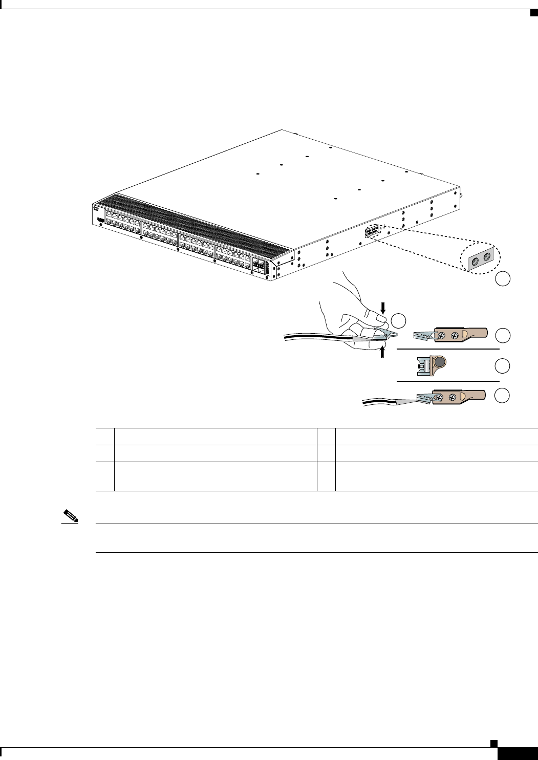
4-11
Cisco Nexus 2000 Series Hardware Installation Guide
Chapter 4 Installing a Cisco Nexus Fabric Extender
Grounding the System
Figure 4-1 shows how to attach the ESD wrist strap to the system ground lug screw for the Cisco Nexus
2000 Series FEX.
Figure 4-1 Attaching the ESD Wrist Strap to the System Ground Lug Screw for a Cisco Nexus
2000 Series FEX
Note For the Cisco Nexus 2300 Series FEX, the ground lug holes have been moved from the side to the rear
of the system. Figure 4-2. shows the Cisco Nexus 2348UPQ FEX.
1ESD ground strap 4Clip installed (behind screw)
2Clip and grounding lug 5System ground connector
3Side view of grounding lug (clip slid behind
screw)
192529
2
1
3
4
5
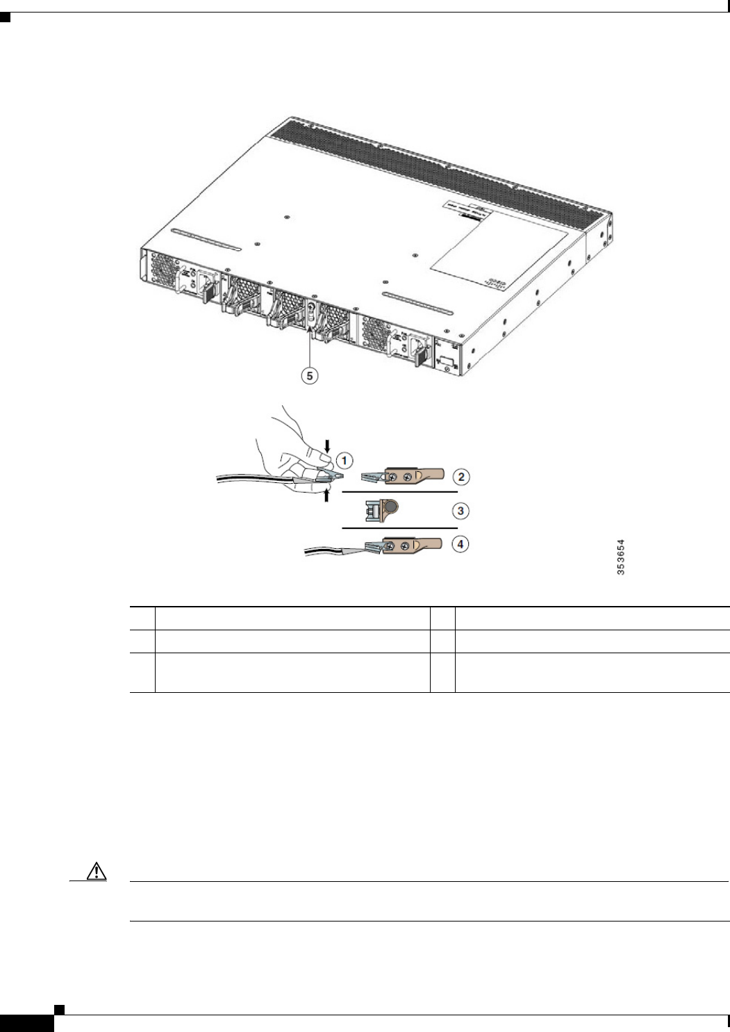
4-12
Cisco Nexus 2000 Series Hardware Installation Guide
Chapter 4 Installing a Cisco Nexus Fabric Extender
Grounding the System
Figure 4-2 Cisco Nexus 2300 Series FEX Ground Lug Location
In addition, follow these guidelines when handling these devices:
•Handle carriers by available handles or edges only; avoid touching the printed circuit boards or
connectors.
•Place a removed component board-side-up on an antistatic surface or in a static-shielding container.
If you plan to return the component to the factory, immediately place it in a static-shielding
container.
•Never attempt to remove the printed circuit board from the metal carrier.
Caution For safety, periodically check the resistance value of the antistatic strap. The measurement should be
between 1 and 10 megohm (Mohm).
1ESD ground strap 4Clip installed (behind screw)
2Clip and grounding lug 5Ground Lug
3Side view of grounding lug (clip slid behind
screw)

4-13
Cisco Nexus 2000 Series Hardware Installation Guide
Chapter 4 Installing a Cisco Nexus Fabric Extender
Grounding the System
Establishing the System Ground
This section describes how to connect a system ground to the Cisco Nexus 2000 and 2300 Series FEXs.
Note This system ground is also referred to as the network equipment building system (NEBS) ground.
You must use the system (NEBS) ground on AC-powered systems if you are installing this equipment in
a U.S. or European Central Office.
The system (NEBS) ground provides additional grounding for EMI shielding requirements and
grounding for the low-voltage supplies (DC-DC converters) on the devices and is intended to satisfy the
Telcordia Technologies NEBS requirements for supplemental bonding and grounding connections. You
must observe the following system grounding guidelines for your chassis:
•You must install the system (NEBS) ground connection with any other rack or system power ground
connections that you make. The system ground connection is required if this equipment is installed
in a U.S. or European Central Office.
•You must connect both the system (NEBS) ground connection and the power supply ground
connection to an earth ground. The system (NEBS) ground connection is required if this equipment
is installed in a U.S. or European Central Office.
•You do not need to power down the chassis because the Cisco Nexus FEX is equipped with AC-input
power supplies.
Required Tools and Equipment
To connect the system ground, you need the following tools and materials:
•Grounding lug—A two-hole standard barrel lug that supports up to 6 AWG wire. This lug is supplied
as part of accessory kit.
•Grounding screws—Two M4 x 8mm (metric) pan-head screws. The screws are supplied as part of
the accessory kit.
•Grounding wire—Not supplied as part of the accessory kit. The grounding wire should be sized
according to local and national installation requirements. Depending on the power supply and
system, a 12 AWG to 6 AWG copper conductor is required for U.S. installations. Commercially
available 6 AWG wire is recommended. The length of the grounding wire depends on the proximity
of the device to proper grounding facilities.
•No. 1 Phillips screwdriver.
•Crimping tool to crimp the grounding wire to the grounding lug.
•Wire-stripping tool to remove the insulation from the grounding wire.
4-14
Cisco Nexus 2000 Series Hardware Installation Guide
Chapter 4 Installing a Cisco Nexus Fabric Extender
Grounding the Chassis
Grounding the Chassis
The chassis has a grounding pad with two threaded M4 holes for attaching a grounding lug.
Warning
When installing or replacing the unit, the ground connection must always be made first and
disconnected last.
Statement 1046
Caution We recommend that you ground the chassis, even if the rack is already grounded.
Caution You must ground all power supplies. The receptacles of the AC power cables used to provide power to
the chassis must be the grounding type, and the grounding conductors should connect to protective earth
ground at the service equipment.
Warning
When installing or replacing the unit, the ground connection must always be made first and
disconnected last.
Statement 1046
Caution Grounding the chassis is required if you are using DC power supplies, even if the rack is already
grounded. A grounding pad with two threaded M4 holes is provided on the chassis for attaching a
grounding lug. The ground lug must be NRTL listed. In addition, the copper conductor (wires) must be
used and the copper conductor must comply with the NEC code.
To attach the grounding lug and cable to the chassis, follow these steps:
Step 1 Use a wire-stripping tool to remove approximately 0.75 inches (19 mm) of the covering from the end of
the grounding cable.
Step 2 Insert the stripped end of the grounding cable into the open end of the grounding lug.
Step 3 Use the crimping tool to secure the grounding cable in the grounding lug.
Step 4 Remove the adhesive label from the grounding pad on the chassis.
Step 5 Place the grounding lug against the grounding pad so that there is solid metal-to-metal contact, and insert
the two M4 screws with washers through the holes in the grounding lug and into the grounding pad.
Step 6 Ensure that the lug and cable do not interfere with other equipment.
Step 7 Prepare the other end of the grounding cable and connect it to an appropriate grounding point in your
site to ensure adequate earth ground.
Starting the Cisco Nexus Fabric Extender
This section describes how to power up the device and verify the hardware operation.

4-15
Cisco Nexus 2000 Series Hardware Installation Guide
Chapter 4 Installing a Cisco Nexus Fabric Extender
Starting the Cisco Nexus Fabric Extender
Note Do not connect the Ethernet port to the LAN until the initial device configuration has been performed.
For instructions on configuring the device, see the Cisco Nexus 2300 Series Fabric Extender Software
Configuration Guide. For instructions on connecting to the console port, see the “Connecting to the
1-Gigabit Ethernet Port” section on page 5-2.
Warning
When installing or replacing the unit, the ground connection must always be made first and
disconnected last.
Statement 1046
To power up the device and verify the hardware operation, follow these steps:
Step 1 Verify that the empty power supply bays have filler panels installed, the faceplates of all modules are
flush with the port side exhaust of the chassis, and the captive screws of the power supplies, fan tray, and
all expansion modules are tight.
Step 2 Verify that the power supply and the fan trays are installed.
Note Depending on the outlet receptacle on your power distribution unit, you may need the optional
jumper power cord to connect the Cisco Nexus 2000 Series FEX to your outlet receptacle. See
the “Jumper Power Cord” section on page C-8.
Step 3 Ensure that the device is adequately grounded as described in the “Grounding the System” section on
page 4-7.
Step 4 If you are installing an AC power supply, connect the power supply to an AC power source as follows:
a. Plug the power cable into the power receptacle on the power supply.
b. Attach the other end of the power cable to the AC power source.
c. If you are connecting cables to a Cisco Nexus 2148T power supply, flip the switch above the AC
receptacle on the power supply to ON.
d. Verify that the power supply is functioning by making sure that the OK LED turns green and the
FAULT LED is off.
Step 5 If you are installing a DC power supply, connect the power supply to a DC power source as follows:
a. Make sure that the DC power source is turned off at the circuit breaker.
b. Connect a negative cable from the power source to the positive (+) terminal on the power supply and
fasten with the screw from that terminal.
c. Connect a positive cable from the power source to the negative (-) terminal on the power supply and
fasten with the screw from that terminal.
d. Turn on the power at the circuit breaker.
e. Verify that the power supply is functioning by making sure that the OK LED turns green and the
FAULT LED is off.
Step 6 Listen for the fans; they should begin operating when the power cable is plugged in.

4-16
Cisco Nexus 2000 Series Hardware Installation Guide
Chapter 4 Installing a Cisco Nexus Fabric Extender
Removing and Installing Components
Step 7 After the device boots, verify that the LED operation is as follows:
•Power supply—The system status LED is green.
•After initialization, the system status LED is green, indicating that all chassis environmental
monitors are reporting that the system is operational. If this LED is orange or red, one or more
environmental monitor is reporting a problem.
•The Link LEDs for the Ethernet connector should not be on unless the cable is connected.
If a component is not operating correctly, remove and reinstall that component. If it still does not operate
correctly, contact your customer service representative for a replacement.
Note If you purchased this product through a Cisco reseller, contact the reseller directly for technical
support. If you purchased this product directly from Cisco, contact Cisco Technical Support at
this URL: http://www.cisco.com/en/US/support/tsd_cisco_worldwide_contacts.html.
Step 8 Verify that the system software has booted and the device has initialized without error messages.
If you cannot resolve an issue, contact your customer service representative.
Step 9 Complete the worksheets provided in “Site Preparation and Maintenance Records” for future reference.
Removing and Installing Components
This section describes how to remove and install components on the Cisco Nexus 2000 and 2300 Series
FEXs.
This section includes the following topics:
•Removing and Installing Power Supplies, page 4-16
•Removing and Installing a Fan, page 4-19
•Removing and Installing the Fan Tray, page 4-21
•Removing the Cisco Nexus Fabric Extender, page 4-22
Caution To prevent ESD damage, wear grounding wrist straps during these procedures and handle modules by
the carrier edges only.
Removing and Installing Power Supplies
The Cisco Nexus 2000 Series FEX supports two power supplies, but the FEX uses only one power supply
for operations. The other power supply is for redundancy.
Caution Whenever you replace a power supply, make sure that it has the same direction of airflow as the rest of
the module in the switch (all fan tray and power supply modules must have the same direction of airflow
and the same color designation for the airflow direction or else the switch can over heat and shut down.

4-17
Cisco Nexus 2000 Series Hardware Installation Guide
Chapter 4 Installing a Cisco Nexus Fabric Extender
Removing and Installing Components
Note If you power up a FEX with power supply and fan tray modules that have different directions of airflow,
an error condition will occur and the switch can over heat and shut down. With this error condition, you
must shut down the switch to replace the modules that do not take in cool air from the cold aisle. After
you ensure that all of the modules have the same direction of airflow and that they take in cooling air
from the cold aisle, you can power up the FEX.
This section includes the following topics:
•Removing an AC Power Supply, page 4-17
•Installing an AC Power Supply, page 4-17
•Removing a DC Power Supply, page 4-18
•Installing a DC Power Supply, page 4-19
Note You can replace a faulty power supply while the system is operating if the other power supply is
functioning.
Removing an AC Power Supply
Caution If you are using the Cisco Nexus 2000 or 2300 Series FEX with one power supply, removing the power
supply causes the device to shut down. If you are using two power supplies and you remove one of them,
the device continues to operate.
To remove an AC power supply, follow these steps:
Step 1 Pull the power cord out from the power receptacle on the power supply.
Step 2 Release the power supply from the chassis as follows:
•If you are removing a power supply from a Cisco Nexus 2148T chassis, loosen the captive screw
and then pull the power supply part way out of the chassis.
•If you are removing a power supply from a Cisco Nexus 2248T, 2232PP, or 2224TP chassis, push
and hold the thumb latch to the left and pull the power supply part way out of the chassis.
Step 3 Place your other hand under the power supply to support it while you slide it out of the chassis.
Step 4 If the power supply bay is to remain empty, install a blank power supply filler panel.
Installing an AC Power Supply
Caution Be sure that the power supply that you are installing has the same airflow direction as the fan tray module
and the other power supply. Either all of the modules must have port-side exhaust airflow (blue or no
color on the front of the module) or all of the modules must have port-side intake airflow (red or black
color on the front of the module). To prevent over heating, the switch does not support more than one
airflow direction for the modules in the chassis.

4-18
Cisco Nexus 2000 Series Hardware Installation Guide
Chapter 4 Installing a Cisco Nexus Fabric Extender
Removing and Installing Components
To install a power supply, follow these steps:
Step 1 Ensure that the system (earth) ground connection has been made for the chassis. For ground connection
instructions, see the “Grounding the System” section on page 4-7.
Step 2 If the power supply bay has a filler panel, remove it from the slot as follows:
•If you are removing a filler panel from a Cisco Nexus 2248TP, 2232PP, or 2224TP FEX, push its
thumb latch to the left and pull the panel out of the chassis.
•If you are removing a filler panel from a Cisco Nexus 2148T FEX, loosen its captive screw, and then
pull the panel out of the power supply bay.
Step 3 Hold the replacement power supply by its handle and position it so that the captive screw is on the left,
and then slide it into the power supply bay, ensuring that the power supply is fully seated in the bay.
Step 4 Secure the power supply to the chassis as follows:
•If you are installing a Cisco Nexus 2248TP, 2232PP, or 2224TP FEX, make sure that the thumb latch
engages with the chassis so that the power supply is held in the slot.
•If you are installing a Cisco Nexus 2148T, fasten the power supply to the chassis by screwing its
captive screw into its hole in the chassis and tightening it.
Note Depending on the outlet receptacle on your power distribution unit, you may need the optional
jumper power cord to connect the Cisco Nexus 2000 Series FEX to your outlet receptacle. See
the “Jumper Power Cord” section on page C-8.
Step 5 Connect the other end of the power cable to an AC power source.
Caution In a system with dual power supplies, connect each power supply to a separate power source.
If a power source failure occurs, the second source will most likely still be available.
Step 6 Verify power supply operation by checking that the power supply LED is green. For information about
what the power supply LEDs indicate, see the “Power Supply Status” section on page E-3.
Removing a DC Power Supply
Caution If you are using the Cisco Nexus 2200 platform FEX with one DC power supply, removing the power
supply causes the device to shut down. If you are using two power supplies and you remove one of them,
the device continues to operate.
To remove a DC power supply, follow these steps:
Step 1 Shut off the DC power to the power supply at the circuit breaker. Make sure that both LEDs are off.
Step 2 Unfasten the positive power cable from the negative (-) terminal.
Step 3 Unfasten the negative power cable from the positive (+) terminal.
Step 4 Press the thumb latch to disengage the power supply from the chassis and use the handle to pull it part
way out of the chassis.

4-19
Cisco Nexus 2000 Series Hardware Installation Guide
Chapter 4 Installing a Cisco Nexus Fabric Extender
Removing and Installing Components
Step 5 Place your other hand under the power supply to support it while you slide it out of the chassis. Place
the power supply on an antistatic surface.
Step 6 If the power supply bay is to remain empty, install a blank power supply filler panel.
Installing a DC Power Supply
In a system with dual power supplies, connect each power supply to a separate power source. If a power
source failure occurs, the second source will most likely still be available.
Caution Be sure that the power supply that you are installing has the same airflow direction as the fan tray module
and the other power supply. Either all of the modules must have port-side exhaust airflow (blue or no
color on the front of the module) or all of the modules must have port-side intake airflow (red or black
color on the front of the module). To prevent over heating, the switch does not support more than one
airflow direction for the chassis.
To install a power supply, follow these steps:
Step 1 Ensure that the system (earth) ground connection has been made for the chassis. For ground connection
instructions, see the “Grounding the System” section on page 4-7.
Step 2 If the power supply bay has a filler panel, push and hold the thumb latch to the left, and then slide the
filler panel out of the power supply bay.
Step 3 Hold the replacement power supply by the handle and position it so that the thumb latch is on the right,
and then slide it into the power supply bay, ensuring that the power supply is fully seated in the bay.
Step 4 Engage the thumb latch so that the power supply is firmly held in place in its slot.
Step 5 Fasten the positive cable to the negative (-) terminal.
Step 6 Fasten the negative cable to the positive (+) terminal.
Step 7 Turn on the power at the circuit breaker.
Step 8 Verify power supply operation by checking that the power supply LED is green. For information about
what the power supply LEDs indicate, see the “Power Supply Status” section on page E-3.
Removing and Installing a Fan
The Cisco Nexus 2300 Series FEXs support three fans, but the FEX needs only two fans for operation.
The other fan is for redundancy. Individual fans are designed to be removed and replaced while the
system is operating, without causing an electrical hazard or damage to the system.
If you are replacing a fan tray on a Cisco Nexus 2200 Series FEX, or Cisco Nexus 2148T FEX, see the
“Removing and Installing the Fan Tray” section on page 4-21.

4-20
Cisco Nexus 2000 Series Hardware Installation Guide
Chapter 4 Installing a Cisco Nexus Fabric Extender
Removing and Installing Components
Caution Be sure that the fan that you are installing has the same airflow direction as the other fans and power
supply modules in the same chassis. Either all of the modules must have port-side exhaust airflow (a blue
or no color on the front of the module) or all of the modules must have port-side intake airflow (red or
black color on the front of the module). If the modules have different airflow directions in the same
chassis, an error condition occurs, the switch can over heat, and the switch can shut down.
Note If you power up a FEX with power supply and fan modules that have different directions of airflow, an
error condition will occur and the switch can over heat and shut down. With this error condition, you
must shut down the switch to replace the modules that do not take in cool air from the cold aisle. After
you ensure that all of the modules have the same direction of airflow and take in cooling air from the
cold aisle, you can power up the FEX.
This section includes the following topics:
•Removing a Fan, page 4-20
•Installing a Fan, page 4-20
Removing a Fan
Warning
When removing the fan tray, keep your hands and fingers away from the spinning fan blades. Let the
fan blades completely stop before you finish removing the fan tray.
Statement 258
To remove a fan, follow these steps:
Step 1 Pinch the two protruding tabs of the fan towards each other to release the latch and pull the fan outward.
Step 2 Pull the fan clear of the chassis and set it on an antistatic surface or repack it in packing materials.
Installing a Fan
To install a fan, follow these steps:
Step 1 Place the fan into the port-side exhaust chassis cavity so it rests on the chassis, and then push the fan into
the chassis as far as it can go until it is latched in place.
Step 2 Listen for the fan if the device is powered on. You should immediately hear it operating. If you do not
hear it, ensure that the fan is inserted completely in the chassis and the faceplate is flush with the outside
surface of the chassis.
Step 3 Verify that the LED is green. If the LED is not green, the fan is faulty. If this problem occurs, contact
your customer service representative for a replacement part.

4-21
Cisco Nexus 2000 Series Hardware Installation Guide
Chapter 4 Installing a Cisco Nexus Fabric Extender
Removing and Installing Components
Note If you purchased this product through a Cisco reseller, contact the reseller directly for technical support.
If you purchased this product directly from Cisco, contact Cisco Technical Support at this URL:
http://www.cisco.com/c/en/us/support/web/tsd-cisco-worldwide-contacts.html.
Removing and Installing the Fan Tray
The Cisco Nexus 2200 Series FEXs, and Cisco Nexus 2148T FEX, use a fan tray. The fan tray is
designed to be removed and replaced while the system is operating without causing an electrical hazard
or damage to the system, if the replacement is performed within 1 minute.
Caution Be sure that the fan tray that you are installing has the same airflow direction as the other fan tray and
power supply modules in the same chassis. Either all of the modules must have port-side exhaust airflow
(a blue or no color on the front of the module) or all of the modules must have port-side intake airflow
(red or black color on the front of the module). If the modules have different airflow directions in the
same chassis, an error condition occurs, the switch can over heat, and the switch can shut down.
Note If you power up a FEX with power supply and fan tray modules that have different directions of airflow,
an error condition will occur and the switch can over heat and shut down. With this error condition, you
must shut down the switch to replace the modules that do not take in cool air from the cold aisle. After
you ensure that all of the modules have the same direction of airflow and take in cooling air from the
cold aisle, you can power up the FEX.
This section includes the following topics:
•Removing a Fan Tray, page 4-21
•Installing a Fan Tray, page 4-22
Removing a Fan Tray
Warning
When removing the fan tray, keep your hands and fingers away from the spinning fan blades. Let the
fan blades completely stop before you finish removing the fan tray.
Statement 258
To remove a fan tray, follow these steps:
Step 1 Loosen the captive screws on the fan tray by turning them counterclockwise, using a flat-blade or
number 2 Phillips screwdriver if required.
Step 2 Grasp the captive screws of the fan tray and pull it outward.
Step 3 Pull the fan tray clear of the chassis and set it on an antistatic surface or repack it in packing materials.

4-22
Cisco Nexus 2000 Series Hardware Installation Guide
Chapter 4 Installing a Cisco Nexus Fabric Extender
Removing and Installing Components
Note If you remove a fan tray while the system is running, you must install the new fan tray within 1
minute to prevent overheating.
Installing a Fan Tray
To install a fan tray, follow these steps:
Step 1 Hold the fan tray with the sheet metal flange holding the connector on the bottom.
Step 2 Place the fan tray into the port-side exhaust chassis cavity so it rests on the chassis, and then push the
fan tray into the chassis as far as it can go until the captive screw makes contact with the chassis.
Step 3 Tighten the captive screw.
Step 4 Listen for the fans if the device is powered on. You should immediately hear them operating. If you do
not hear them, ensure that the fan tray is inserted completely in the chassis and the faceplate is flush with
the outside surface of the chassis.
Step 5 Verify that the LED is green. If the LED is not green, one or more fans are faulty. If this problem occurs,
contact your customer service representative for a replacement part.
Note If you purchased this product through a Cisco reseller, contact the reseller directly for technical support.
If you purchased this product directly from Cisco, contact Cisco Technical Support at this URL:
http://www.cisco.com/c/en/us/support/web/tsd-cisco-worldwide-contacts.html.
Removing the Cisco Nexus Fabric Extender
Caution The slider rail and port side exhaust rack-mount brackets do not have a stop mechanism when sliding in
and out. If the port side exhaust of the chassis is unfastened from the rack and the chassis slides forward
on the slider rails, it may slip off the end of the rails and fall out of the rack.
To remove the Cisco Nexus 2000 Series FEX from a rack, follow these steps:
Step 1 Ensure that the weight of the FEX is fully supported and that the device is being held by another person.
Step 2 Turn off the power at the circuit breaker.
Step 3 Disconnect the power cord as follows:
•For AC power supplies, disconnect the power cord and the console cables.
•For DC power supplies, disconnect the positive cable from the negative (-) terminal, and disconnect
the negative cable from the positive (+) terminal.
Step 4 Disconnect all ports.
Step 5 Remove the screws that fasten the port side exhaust rack-mount brackets to the mounting rails.

4-23
Cisco Nexus 2000 Series Hardware Installation Guide
Chapter 4 Installing a Cisco Nexus Fabric Extender
Repacking the Cisco Nexus Fabric Extender for Return Shipment
Step 6 Gently slide the chassis toward you, off of the slider rails and out of the rack.
Repacking the Cisco Nexus Fabric Extender for Return Shipment
If you need to return the Cisco Nexus 2000 and 2300 Series FEX, remove the device from the rack by
following the steps in the “Removing the Cisco Nexus Fabric Extender” section on page 4-22, and
repack it for shipment. If possible, use the original packing materials and container to repack the device.
Contact your Cisco customer service representative to arrange for return shipment to Cisco.

4-24
Cisco Nexus 2000 Series Hardware Installation Guide
Chapter 4 Installing a Cisco Nexus Fabric Extender
Repacking the Cisco Nexus Fabric Extender for Return Shipment

CHAPTER
5-1
Cisco Nexus 2000 Series Hardware Installation Guide
5
Connecting a Cisco Nexus Fabric Extender
This chapter describes how to connect the ports on a Cisco Nexus Fabric Extender (FEX).
Caution When running power and data cables in overhead or subfloor cable trays, we strongly recommend that
you have power cables and other potential noise sources as far away as practical from network cabling
that terminates on Cisco equipment. In situations where long parallel cable runs cannot be separated by
at least 3.3 feet (1 m), we recommend that you shield any potential noise sources by housing them in a
grounded metallic conduit.
This chapter includes the following sections:
•Preparing for Network Connections, page 5-2
•Connecting to the 1-Gigabit Ethernet Port, page 5-2
•Connecting to a 10-Gigabit and 40-Gigabit Ethernet Port, page 5-2

5-2
Cisco Nexus 2000 Series Hardware Installation Guide
Chapter 5 Connecting a Cisco Nexus Fabric Extender
Preparing for Network Connections
Preparing for Network Connections
When preparing your site for network connections to the Cisco Nexus FEX, consider the following for
each type of interface, and gather all the required equipment before connecting the ports:
•Cabling required for each interface type
•Distance limitations for each signal type
•Additional interface equipment required
Connecting to the 1-Gigabit Ethernet Port
This section describes how to connect a 1-Gigabit Ethernet port to a host.
The 1-Gigabit Ethernet ports have RJ-45 interfaces. There are 48 1-Gigabit Ethernet server ports.
To connect a 1-Gigabit Ethernet port to a host, follow these steps:
Step 1 Connect the appropriate modular cable to the 1-Gigabit Ethernet port.
Step 2 Connect the other end of the cable to the device.
Connecting to a 10-Gigabit and 40-Gigabit Ethernet Port
This section describes how to connect a 10-Gigabit or 40-Gigabit Ethernet port to a host. There are four
network facing 10-Gigabit Ethernet ports for the Cisco Nexus 2148T and 2248TP, eight for the Cisco
Nexus 2232TM, 2232TM-E, and 2232PP, and two on the Cisco Nexus 2224TP. An SFP+ transceiver is
used to connect to a 10-Gigabit Ethernet port. The Cisco Nexus 2300 Series platform FEXs provide six
network facing 40-Gigabit uplink ports. A QSFP+ transceiver is used to connect to a 40-Gigabit Ethernet
port.
This section includes the following topics:
•Removing and Installing SFP+ Transceivers, page 5-2
•Removing and Installing Cables into SFP+ Transceivers, page 5-4
•Maintaining SFP+ Transceivers and Cables, page 5-6
Removing and Installing SFP+ Transceivers
Caution Excessively removing and installing an SFP transceiver can shorten its life. Do not remove and insert
SFP+ transceivers more often than is necessary. We recommend that you disconnect cables before
installing or removing SFP transceivers to prevent damage to the cable or transceiver.
This section describes how to install and remove an SFP+ transceiver. This section includes the
following topics:
•Installing an SFP+ Transceiver, page 5-3

5-3
Cisco Nexus 2000 Series Hardware Installation Guide
Chapter 5 Connecting a Cisco Nexus Fabric Extender
Connecting to a 10-Gigabit and 40-Gigabit Ethernet Port
•Removing an SFP+ Transceiver, page 5-3
Installing an SFP+ Transceiver
To install an SFP+ transceiver, follow these steps:
Step 1 Attach an ESD-preventive wrist strap and follow its instructions for use.
Step 2 Remove the dust cover from the port cage.
Step 3 Remove the dust cover from the port end of the transceiver.
Step 4 Insert the transceiver into the port as follows:
•If the transceiver has a Mylar tab latch, position the transceiver with the tab on the bottom, and then
gently insert the transceiver into the port until it clicks into place.
•If the transceiver has a bale clasp latch, position the transceiver with the clasp on the bottom, close
the clasp by pushing it up over the transceiver, and then gently insert the transceiver into the port
until it clicks into place.
Caution If the transceiver does not install easily, ensure that it is correctly positioned and the tab or
clasp are in the correct position before continuing.
Note If you cannot install the cable into the transceiver, insert or leave the dust cover in the cable end
of the transceiver.
Removing an SFP+ Transceiver
To remove an SFP+ transceiver, follow these steps:
Step 1 Attach an ESD-preventive wrist strap and follow its instructions for use.
Step 2 If a cable is installed in the transceiver, do one of the following:
a. Record the cable and port connections for later reference.
b. Press the release latch on the cable, grasp the connector near the connection point, and gently pull
the connector from the transceiver.
c. Insert a dust plug into the cable end of the transceiver.
Caution If the transceiver does not remove easily in the next step, push the transceiver completely in
and then ensure that the latch is in the correct position before continuing.
Step 3 Remove the transceiver from the port as follows:
•If the transceiver has a Mylar tab latch, gently pull the tab straight out (do not twist), and then pull
the transceiver out of the port.
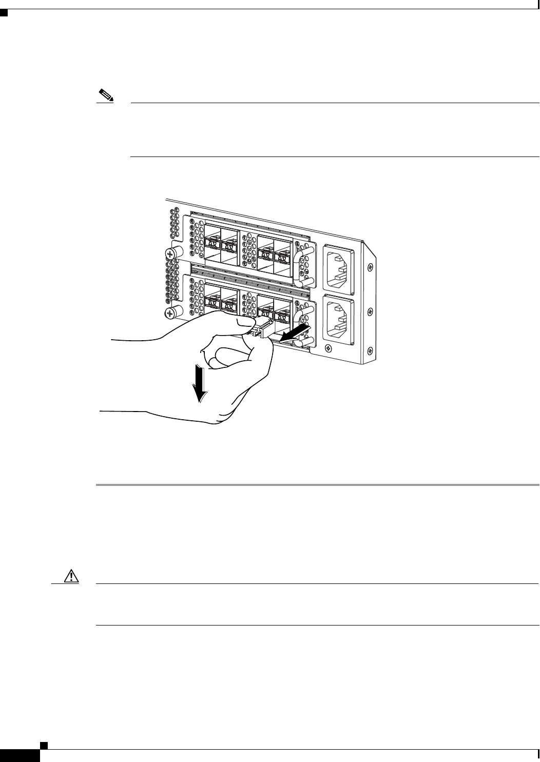
5-4
Cisco Nexus 2000 Series Hardware Installation Guide
Chapter 5 Connecting a Cisco Nexus Fabric Extender
Connecting to a 10-Gigabit and 40-Gigabit Ethernet Port
•If the transceiver has a bale clasp latch, open the clasp by pressing it downward, and then pull the
transceiver out of the port.
Note If you have difficulty removing a bale clasp SFP+ transceiver, you should reseat it by returning
the bale clasp to the up position. Press the SFP+ transceiver inward and upward into the cage.
Next, lower the bale clasp and pull the SFP+ transceiver straight out with a slight upward lifting
force (see Figure 5-1). Be careful not to damage the port cage during this process.
Figure 5-1 Alternate Removal Method for Bale Clasp SFP+ Transceivers
Step 4 Insert a dust cover into the port end of the transceiver and place the transceiver on an antistatic mat or
into a static shielding bag if you plan to return it to the factory.
Step 5 If another transceiver is not being installed, protect the optical cage by inserting a clean cover.
Removing and Installing Cables into SFP+ Transceivers
This section describes how to remove and install cables into and from SFP+ transceivers.
Caution To prevent damage to the copper cables, do not place more tension on them than the rated limit and do
not bend to a radius of less than 1 inch if there is no tension in the cable, or 2 inches if there is tension
in the cable.
This section includes the following topics:
•Installing a Cable into an SFP+ Transceiver, page 5-5
•Removing a Cable from an SFP+ Transceiver, page 5-5
186903

5-5
Cisco Nexus 2000 Series Hardware Installation Guide
Chapter 5 Connecting a Cisco Nexus Fabric Extender
Connecting to a 10-Gigabit and 40-Gigabit Ethernet Port
Removing a Cable from an SFP+ Transceiver
Caution When pulling a cable from a transceiver, grip the body of the connector. Do not pull on the jacket sleeve,
because this action can compromise the fiber-optic termination in the connector.
Caution If the cable does not remove easily, ensure that any latch present on the cable has been released before
continuing.
To remove the cable, follow these steps:
Step 1 Attach an ESD-preventive wrist strap and follow its instructions for use.
Step 2 Press the release latch on the cable, grasp the connector near the connection point, and gently pull the
connector from the transceiver.
Step 3 Insert a dust plug into the cable end of the transceiver.
Step 4 Insert a dust plug onto the end of the cable.
Installing a Cable into an SFP+ Transceiver
Caution To prevent possible damage to the cable or transceiver, install the transceiver in the port before installing
the cable in the transceiver.
To install a cable into a transceiver, follow these steps:
Step 1 Attach an ESD-preventive wrist strap and follow its instructions for use.
Step 2 Remove the dust cover from the connector on the cable.
Step 3 Remove the dust cover from the cable end of the transceiver.
Step 4 Align the cable connector with the transceiver and insert the connector into the transceiver until it clicks
into place.
Caution If the cable does not install easily, ensure that it is correctly positioned before continuing.
For instructions on verifying connectivity, see the Cisco Nexus 2000 Series Fabric Extender Software
Configuration Guide.

5-6
Cisco Nexus 2000 Series Hardware Installation Guide
Chapter 5 Connecting a Cisco Nexus Fabric Extender
Connecting to a 10-Gigabit and 40-Gigabit Ethernet Port
Maintaining SFP+ Transceivers and Cables
You must keep SFP+ transceivers clean and dust free to maintain high signal accuracy and prevent
damage to the connectors. Attenuation (loss of light) is increased by contamination and should be below
0.35 dB.
Follow these maintenance guidelines:
•SFP+ transceivers are static sensitive. To prevent ESD damage, wear an ESD-preventive wrist strap
that is connected to the chassis.
•Do not remove and insert a transceiver more often than is necessary. Repeated removals and
insertions can shorten its life.
•Keep all optical connections covered when not in use. If they become dusty, clean before using to
prevent dust from scratching the fiber-optic cable ends.
•Do not touch ends of connectors to prevent fingerprints and other contamination.
•Clean regularly; the required frequency of cleaning depends upon the environment. In addition,
clean connectors if they are exposed to dust or accidentally touched. Both wet and dry cleaning
techniques can be effective; refer to your site’s fiber-optic connection cleaning procedure.
•Inspect routinely for dust and damage. If damage is suspected, clean and then inspect fiber ends
under a microscope to determine if damage has occurred.

A-1
Cisco Nexus 2000 Series Hardware Installation Guide
APPENDIX
A
Cabinet and Rack Installation
This appendix provides the requirements for cabinet and rack installation and includes the following
sections:
•Cabinet and Rack Requirements, page A-1
•Cable Management Guidelines, page A-3
Cabinet and Rack Requirements
This section provides the requirements for the following types of cabinets and racks, assuming an
external ambient air temperature range of 0 to 104oF (0 to 40oC):
•Standard perforated cabinets
•Solid-walled cabinets with a roof fan tray (bottom to top cooling)
•Standard open racks
Note If you are selecting an enclosed cabinet, we recommend one of the thermally validated types, either
standard perforated or solid-walled with a fan tray.
Note Do not use racks that have obstructions (such as power strips), because the obstructions could impair
access to field-replaceable units (FRUs).
This section includes the following topics:
•General Requirements for Cabinets and Racks, page A-1
•Requirements Specific to Perforated Cabinets, page A-2
•Requirements Specific to Standard Open Racks, page A-2
General Requirements for Cabinets and Racks
The cabinet or rack must be one of the following types:
•Standard 19-in. (48.3 cm) (four-post EIA cabinet or rack, with mounting rails that conform to
English universal hole spacing per section 1 of ANSI/EIA-310-D-1992). See the “Requirements
Specific to Perforated Cabinets” section on page A-2.

A-2
Cisco Nexus 2000 Series Hardware Installation Guide
Appendix A Cabinet and Rack Installation
Cabinet and Rack Requirements
The cabinet or rack must also meet the following requirements:
•The minimum vertical rack space per Cisco Nexus 2000 Series FEX chassis or Cisco Nexus 2300
Series FEX chassis must be one RU (rack units), equal to 1.75 inches (4.4 cm).
•The width between the rack-mounting rails must be at least 17.75 inches (45.0 cm) if the rear of the
device is not attached to the rack. For four-post EIA racks, this measurement is the distance between
the two port side exhaust rails.
•For four-post EIA cabinets (perforated or solid-walled), the requirements are as follows:
–
The minimum spacing for the bend radius for fiber-optic cables should have the port side
exhaust-mounting rails of the cabinet offset from the port side exhaust door by a minimum of
3 inches (7.6 cm).
–
The distance between the outside face of the port side exhaust mounting rail and the outside face
of the back mounting rail should be 23.0 to 30.0 inches (58.4 to 76.2 cm) to allow for
rear-bracket installation.
–
A minimum of 2.5 inches (6.4 cm) of clear space should exist between the side edge of the
chassis and the side wall of the cabinet. No sizeable flow obstructions should be immediately
in the way of chassis air intake or exhaust vents.
Note Optional jumper power cords are available for use in a cabinet. See the “Jumper Power Cord”
section on page C-8.
Requirements Specific to Perforated Cabinets
A perforated cabinet is defined as a cabinet with perforated port side exhaust and rear doors and solid
side walls. In addition to the requirements listed in the “General Requirements for Cabinets and Racks”
section on page A-1, perforated cabinets must meet the following requirements:
•The port side exhaust and rear doors must have at least a 60 percent open area perforation pattern
with at least 15 square inches (96.774 square cm) of open area per rack unit of door height.
•The roof should be perforated with at least a 20 percent open area.
•The cabinet floor should be open or perforated to enhance cooling.
The Cisco R Series rack conforms to these requirements.
Requirements Specific to Standard Open Racks
In addition to the requirements listed in the “General Requirements for Cabinets and Racks” section on
page A-1, if mounting the chassis in an open rack (no side panels or doors), ensure that the rack meets
the following requirements:
•The minimum vertical rack space per chassis must be two rack units (RU), equal to 3.47 inches (8.8
cm).
•The horizontal distance between the chassis and any adjacent chassis should be 6 inches (15.2 cm),
and the distance between the chassis air vents and any walls should be 2.5 inches (6.4 cm).

A-3
Cisco Nexus 2000 Series Hardware Installation Guide
Appendix A Cabinet and Rack Installation
Cable Management Guidelines
Cable Management Guidelines
To help with cable management, you might want to allow additional space in the rack above and below
the chassis to make it easier to route as many as 56 fiber or copper cables through the rack.

A-4
Cisco Nexus 2000 Series Hardware Installation Guide
Appendix A Cabinet and Rack Installation
Cable Management Guidelines

B-1
Cisco Nexus 2000 Series Hardware Installation Guide
APPENDIX
B
Technical Specifications
This appendix describes the technical specifications for the Cisco Nexus Fabric Extenders (FEXs) and
includes the following sections:
•Power Specifications, page B-1
•Environmental Specifications, page B-6
•Physical Specifications, page B-6
•Transceiver Specifications, page B-7
•Airflow Optimization Accessories, page B-9
Note Specifications for cables and connectors are provided in Appendix C, “Cable and Port Specifications.”
Power Specifications
This section describes the power specifications for the Cisco Nexus Fabric Extenders.
The power supplies connect directly to the system through connectors attached to the baseboard through
cables. One connector is on the baseboard for each power supply. AC input is through an IEC connector
mounted on the power supply port side exhaust panel. Table B-1 lists the specifications for the FEX
power supplies.

B-2
Cisco Nexus 2000 Series Hardware Installation Guide
Appendix B Technical Specifications
Power Specifications
Table B-1 Power Specifications for the Cisco Nexus Fabric Extender
Cisco Nexus
Fabric Extender
Power Supply
N2K-PAC-200W N2200-PAC-400W
N2200-PAC-400W-B
N2200-PDC-400W
N2200-PDC-350W-B
FEXs Cisco Nexus 2148T Cisco Nexus 2348TQ and
2348UPQ, Cisco Nexus
2248TP-E, 2248TP, 2232PP,
2224TP, 2248PQ and
2232TM
Cisco Nexus 2348UPQ,
Cisco Nexus 2248TP-E,
2248TP, 2232PP, 2248PQ
and 2224TP
Typical Input
Operating Power
165 W 187 W @ 30M, 239 W
@100M to 300 W (Cisco
Nexus 2348TQ)
125 W to 200 W (Cisco Nexus
2348UPQ)
110 W (Cisco Nexus
2248TP-E and 2248TP)
270 W (Cisco Nexus 2232PP)
350 W to 386 W (Cisco Nexus
2232TM)
110 W (Cisco Nexus
2248TP-E and 2248TP)
270 W (Cisco Nexus 2232PP)
95 W (Cisco Nexus 2224TP)
Maximum
Output Power
200 W 400 W 350 W
Input Voltage 90 to 264 VAC 90 to 264 VAC
N2K-PDC-400W:
–40 to –72 VDC
–40 to –72 VDC
Frequency 50 to 60 Hz 50 to 60 Hz
N2K-PDC-400W:
N/A
N/A
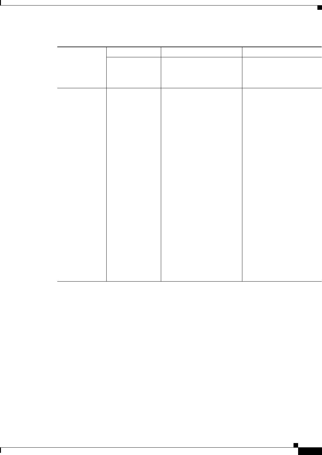
B-3
Cisco Nexus 2000 Series Hardware Installation Guide
Appendix B Technical Specifications
Power Specifications
Input Current 1.5 A/2.2 A*
(typical/maximum)
* The Input
currents listed for
110 V; divide by
two for 220 V
Cisco Nexus 2348TQ:
1.7 A/2.17 A*
(typical/maximum)
Cisco Nexus 2348UPQ:
1.14 A/1.82 A*
(typical/maximum)
Cisco Nexus 2248TP-E:
1.0 A/1.2 A*
(typical/maximum)
Cisco Nexus 2248TP:
1.0 A/1.2 A*
(typical/maximum)
Cisco Nexus 2232PP:
2.5 A/4.1 A*
(typical/maximum)
Cisco Nexus 2224TP:
0.75 A/0.9 A*
(typical/maximum)
Cisco Nexus 2232TM
3.18 A/3.51 A*
(typical/maximum)
* Input currents listed for 110
V; divide by two for 220 V
Cisco Nexus 2248TP-E:
1.0 A/1.2 A*
(typical/maximum)
Cisco Nexus 2248TP:
1.0 A/1.2 A*
(typical/maximum)
Cisco Nexus 2232PP:
2.5 A/4.1 A*
(typical/maximum)
Cisco Nexus 2224TP:
0.75 A/0.9 A*
(typical/maximum)
* Input currents listed for 110
V; divide by two for 220 V
Table B-1 Power Specifications for the Cisco Nexus Fabric Extender (continued)
Cisco Nexus
Fabric Extender
Power Supply
N2K-PAC-200W N2200-PAC-400W
N2200-PAC-400W-B
N2200-PDC-400W
N2200-PDC-350W-B

B-4
Cisco Nexus 2000 Series Hardware Installation Guide
Appendix B Technical Specifications
Power Specifications
Output Current 11.5 A/16.7 A
(typical/maximum)
Cisco Nexus 2348TQ:
14.8 A/24.75 A
(typical/maximum)
Cisco Nexus 2348UPQ:
9.9 A/16.5 A
(typical/maximum)
Cisco Nexus 2248TP-E:
8 A/10 A (typical/maximum)
Cisco Nexus 2248TP:
8 A/10 A (typical/maximum)
Cisco Nexus 2232PP:
20 A/33 A (typical/maximum)
Cisco Nexus 2224TP:
5 A/7 A (typical/maximum)
Cisco Nexus 2232TM:
26 A/28.9 A
(typical/maximum)
Cisco Nexus 2248TP-E:
8 A/10 A (typical/maximum)
Cisco Nexus 2248TP:
8 A/10 A (typical/maximum)
Cisco Nexus 2232PP:
20 A/33 A
(typical/maximum)
Cisco Nexus 2224TP:
5 A/7 A (typical/maximum)
Efficiency 84 percent at
typical power draw
90/92 percent (110/240 Vin)
at typical power draw
88/91 percent (110/240 Vin)
at max power draw
N2K-PDC-400 W:
88% (–48 Vin) at typical
power draw
85% (–48 Vin) at maximum
power draw
88% (-48Vin) at typical
power draw
85% (-48Vin) at maximum
power draw
RoHS
Compliance
RoHS-5 compliant RoHS-6 compliant RoHS-6 compliant
Hot Swappable Yes Yes Yes
Table B-1 Power Specifications for the Cisco Nexus Fabric Extender (continued)
Cisco Nexus
Fabric Extender
Power Supply
N2K-PAC-200W N2200-PAC-400W
N2200-PAC-400W-B
N2200-PDC-400W
N2200-PDC-350W-B

B-5
Cisco Nexus 2000 Series Hardware Installation Guide
Appendix B Technical Specifications
Power Specifications
Heat Dissipation 670 BTU/hr Cisco Nexus 2348TQ:
638/1023 BTU/hour
(typical/maximum)
Cisco Nexus 2348UPQ:
426/682 BTU/hour
(typical/maximum)
Cisco Nexus 2248TP-E:
322/403 BTU/hour
(typical/maximum)
Cisco Nexus 2248TP:
322/403 BTU/hour
(typical/maximum)
Cisco Nexus 2232PP:
806/1330 BTU/hour
(typical/maximum)
Cisco Nexus 2224TP:
202/282 BTU/hour
(typical/maximum)
Cisco Nexus 2232TM:
1176/1297 BTU/hour
(typical/maximum)
Cisco Nexus 2248TP-E:
322/403 BTU/hour
(typical/maximum)
Cisco Nexus 2248TP:
322/403 BTU/hour
(typical/maximum)
Cisco Nexus 2232PP:
806/1330 BTU/hour
(typical/maximum)
Cisco Nexus 2224TP:
202/282 BTU/hour
(typical/maximum)
Power Cord
Rating
3 A@100 Vin / 1.5
A@240 Vin
maximum
6 A@100 Vin / 3 A@240 Vin
maximum
N2K-PDC-400W:
15 A@-48 Vin/8 A@-60 Vin
maximum
15A@-48Vin/8A@-60Vin
maximum
Cubic Inches 51 in^3 39 in^3 39 in^3
Power Density 3.9 W/in^3 10.2 W/in^3 10.2 W/in^3
Operating
Temperature
50°C 50°C 50°C
Cooling Internal fans to cool
the supply
Internal fans to cool the supply Internal fans to cool the supply
Input connector AC connector in the
power supply face
AC connector in the power
supply face
AC connector in the power
supply face
Table B-1 Power Specifications for the Cisco Nexus Fabric Extender (continued)
Cisco Nexus
Fabric Extender
Power Supply
N2K-PAC-200W N2200-PAC-400W
N2200-PAC-400W-B
N2200-PDC-400W
N2200-PDC-350W-B

B-6
Cisco Nexus 2000 Series Hardware Installation Guide
Appendix B Technical Specifications
Environmental Specifications
Environmental Specifications
Table B-2 lists the environmental specifications for a FEX.
The Cisco Nexus 2348TQ, Cisco Nexus 2348UPQ, Cisco Nexus 2232PP, 2232TM, and the Cisco Nexus
2248TP-ETP FEXs can operate in a horizontal or vertical rack mount configuration.
Physical Specifications
Table B-3 lists the dimensions and weights for the Cisco Nexus Fabric Extenders.
Output connector DC output
connector in the
back
DC output connector in the
back
DC output connector in the
back
Supply Indicators Supply Health:
Green indicates the
power supply is
operational and red
indicates a fault.
AC good indicator:
Solid green
indicates that AC is
present and is
within the supply
specifications.
Supply Health: Green
indicates the power supply is
operational and amber
indicates a fault.
AC good indicator: Solid
green indicates that AC is
present and is within the
supply specifications.
Supply Health: Green
indicates the power supply is
operational and amber
indicates a fault.
Table B-1 Power Specifications for the Cisco Nexus Fabric Extender (continued)
Cisco Nexus
Fabric Extender
Power Supply
N2K-PAC-200W N2200-PAC-400W
N2200-PAC-400W-B
N2200-PDC-400W
N2200-PDC-350W-B
Table B-2 Environmental Specifications for the Cisco Nexus Fabric Extender
Description Specification
Temperature, operating 32 to 104°F (0 to 40°C);
32 to 131°F (0 to 55°C) for the Cisco Nexus 2348TQ and 2348UPQ
Temperature, nonoperating –4 to 158°F (–20 to 70°C);
–40 to 158°F (–40 to 70°C) for the Cisco Nexus 2348TQ and
2348UPQ
Humidity (RH), noncondensing 5 to 95%
Altitude 0 to 10000 ft (0 to 3000 m)

B-7
Cisco Nexus 2000 Series Hardware Installation Guide
Appendix B Technical Specifications
Transceiver Specifications
Transceiver Specifications
This section describes the transceiver specifications for the Cisco Nexus FEX. This section includes the
following topics:
•SFP+ Optical Transceiver Specifications, page B-8
Table B-3 Physical Specifications for Installing the Cisco Nexus Fabric Extender
Cisco Nexus Fabric Extender
Dimensions (Height x Width x Depth)1
1. Dimensions are presented for only the chassis rack size and service clearance requirements.
Weight2
2. Combine the chassis, power supply, and fan tray weights for the overall weight of the switch to be installed. Remember to
double the power supply weights if there are two power supplies installed in the FEX.
Inches Centimeters
Cisco Nexus 2348TQ chassis 1.72 x 17.3 x 17.07 in. 4.37 x 43.94 x 43.36 cm 17.0 lb (7.7 kg)
Power supply
Fan tray
—
—
—
—
2.2 lb (1.0 kg)
1.4 lb (0.6 kg)
Cisco Nexus 2348UPQ chassis 1.72 x 17.3 x 14.05 in. 4.37 x 43.94 x 35.69 cm 15.5 lb (7.0 kg)
Power supply
Fan tray
—
—
—
—
2.2 lb (1.0 kg)
1.4 lb (0.6 kg)
Cisco Nexus 2248TP-E chassis 1.72 x 17.3 x 17.7 in. 4.37 x 43.94 x 44.96 cm 17.7 lb (8.03 kg)
Power supply
Fan tray
—
—
—
—
2.2 lb (1.0 kg)
1.4 lb (0.6 kg)
Cisco Nexus 2248TP chassis 1.72 x 17.3 x 17.7 in. 4.37 x 43.94 x 44.96 cm 17.7 lb (8.03 kg)
Power supply
Fan tray
—
—
—
—
2.2 lb (1.0 kg)
1.4 lb (0.6 kg)
Cisco Nexus 2248PQ chassis 1.72 x 17.3 x 17.7 in. 4.37 x 43.94 x 44.96 cm 17.5 lb (8.0 kg)
Power supply
Fan tray
—
—
—
—
2.2 lb (1.0 kg)
1.8 lb (0.8 kg)
Cisco Nexus 2232PP chassis 1.72 x 17.3 x 17.7 in. 4.37 x 43.94 x 44.96 cm 18.3 lb (8.3 kg)
Power supply
Fan tray
—
—
—
—
2.2 lb (1.0 kg)
1.8 lb (0.8 kg)
Cisco Nexus 2224TP chassis 1.72 x 17.3 x 17.7 in. 4.37 x 43.94 x 44.96 cm 16.6 lb (1.0 kg)
Power supply
Fan tray
—
—
—
—
2.2 lb (1.0 kg)
1.4 lb (0.6 kg)
Cisco Nexus 2148T chassis 1.72 x 17.3 x 20.0 in. 4.37 x 43.94 x 50.8 cm 18.0 lb (8.2 kg)
Power supply
Fan tray
—
—
—
—
1.5 lb (0.7 kg)
1.5 lb (0.7 kg)
Cisco Nexus 2232TM chassis 1.72 x 17.3 x 17.7 in. 4.37 x 43.94 x 44.96 cm 18.5 lb (8.4 kg)
Power supply
Fan tray
—
—
—
—
2.2 lb (1.0 kg)
1.8 lb (0.8 kg)
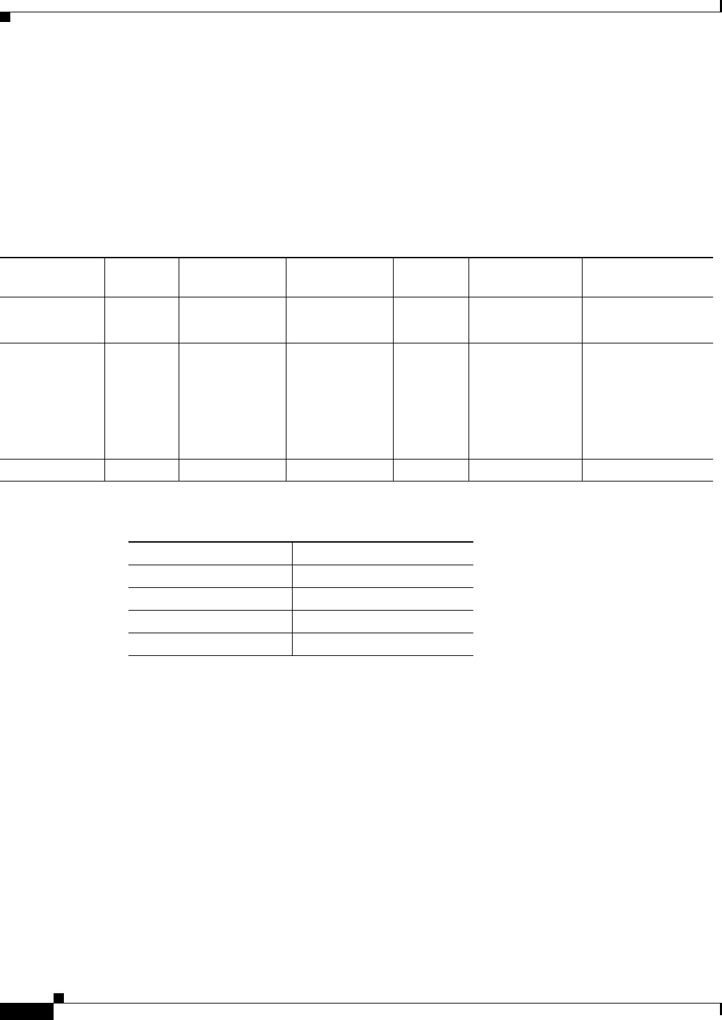
B-8
Cisco Nexus 2000 Series Hardware Installation Guide
Appendix B Technical Specifications
Transceiver Specifications
SFP+ Optical Transceiver Specifications
This section provides the general and environmental specifications for the SFP+ transceivers used with
optical cables.
For the general specifications that apply to SFP+ transceivers, see Table B-4. For the environmental
specifications, see Table B-5.
For information about Cisco 10GBASE SFP modules, refer to the Cisco Transceiver Modules Datasheet.
SFP+ Copper Transceiver Specifications
This section provides the general and environmental specifications for the SFP+ transceivers used with
copper cables.
For the cable specifications that apply to SFP+ copper transceivers, see Table B-6.
Table B-4 SFP+ Transceiver General Specifications
Transceiver Cable Type Connector Type Wavelength (nm)
Core Size
(microns)
Modal Bandwidth
(MHz-km)
Maximum Cable
Distance
N2200 FET MMF Dual LC/PC 850 50
50
500
2000
82 feet (25 meters)
328 feet (100 meters)
SFP-10G-SR MMF Dual LC/PC 850 62.5
62.5
50.0
50.0
50.0
160
200
400
500
2000
85 feet (26 meters)
108 feet (33 meters)
216 feet (66 meters)
269 feet (82 meters)
984 feet (984 meters)
SFP-10G-LR SMF Dual LC/PC 1310 G.652 fiber — 6.2 miles (10 km)
Table B-5 Environmental and Power Specifications for the 10-Gbps SFP+ Optical Transceivers
Parameter1
1. Absolute maximum ratings are those values beyond which damage to
the device may occur if these limits are exceeded for other than a short
period of time.
Specification
Storage temperature –40 to 185°F (–40 to 85°C)
Case temperature2
2. Functional performance is not intended, device reliability is not
implied, and damage to the device may occur over an extended period
of time between absolute maximum ratings and the recommended
operating conditions.
32 to 158°F (0 to 70°C)
Relative humidity 5 to 95%
Module supply voltage 3.1 to 3.5 V

B-9
Cisco Nexus 2000 Series Hardware Installation Guide
Appendix B Technical Specifications
Airflow Optimization Accessories
Airflow Optimization Accessories
This section describes the airflow optimization accessories for the Cisco Nexus FEX.
For the details of the Cisco Nexus airflow extension sleeve and the Cisco Nexus airflow vent, see
Table B-7.
Table B-6 Cable Specifications for the 10-Gbps SFP+ Copper Transceivers
Transceiver Cable Length
SFP-H10GB-CU7M 23.0 feet (7 meters)
SFP-H10GB-CU10M 32.8 feet (10 meters)
Table B-7 Airflow Optimization Accessories
Accessories Airflow Extension Sleeve Airflow Vent
PID NXA-AIRFLOW-SLV (2200 Series)
NXA-AIRFLOW-SLV-E (2300 Series)
NXA-ACC-KIT-BAV
Name Cisco Nexus Airflow Extension Sleeve Cisco Nexus Airflow Vent
Description Optimizes airflow in port side exhaust
airflow deployments (port side exhaust)
for alignment of port in back of rack and
extension of power supply side of
chassis to port side exhaust of rack with
airflow sleeve
Optimizes airflow in port side intake top
of rack deployments (port side intake).
Airflow vent consists of metallic cover to
place on the upper exhaust of the FEX
port side and mounting rails with snap on
holes for airflow vent.
Dimensions
(height x width x
depth)
1.72" (1RU) x 17.3" x 8.5"(fully
retracted)* or 12.9"(fully extended)*
*Adjustable depth for the FEX, between
26 and 30 inches
Vent cover is part of the mounting
hardware kit and its size is meaningless
to overall form factor of the chassis:
0.42" x 17.53" x 2.56"
Weight 5.7 lbs or 2.6 kg 0.42 lbs or 0.19 kg

B-10
Cisco Nexus 2000 Series Hardware Installation Guide
Appendix B Technical Specifications
Airflow Optimization Accessories

C-1
Cisco Nexus 2000 Series Hardware Installation Guide
APPENDIX
C
Cable and Port Specifications
This appendix provides cable and port specifications for the Fabric Extender (FEX) and includes the
following sections:
•Supported Power Cords and Plugs, page C-1
•Jumper Power Cord, page C-8
Supported Power Cords and Plugs
Each power supply has a separate power cord. Standard power cords or jumper power cords are available
for connection to a power distribution unit that has IEC 60320 C19 outlet receptacles. The jumper power
cords, for use in cabinets, are available as an optional alternative to the standard power cords.
Power Cords
The standard power cords have an IEC C19 connector on the end that plugs into the device. The optional
jumper power cords have an IEC C19 connector on the end that plugs into the device and an IEC C20
connector on the end that plugs into an IEC C19 outlet receptacle.
Note Only the regular power cords or jumper power cords provided with the device are supported.
Table C-1 lists the AC power cords for the Cisco Nexus Fabric Extender and provides their lengths in
feet and meters.
Table C-1 AC Power Cords for the Cisco Nexus Fabric Extender
Description
Length Power Cord Reference
IllustrationFeet Meters
SFS-250V-10A-AR
Power Cord, 250 VAC 10 A IRAM 2073 Plug
Argentina
8.2 2.5 Figure C-1
CAB-9K10A-AU
250 VAC 10 A 3112 Plug,
Australia
8.2 2.5 Figure C-2

C-2
Cisco Nexus 2000 Series Hardware Installation Guide
Appendix C Cable and Port Specifications
Supported Power Cords and Plugs
SFS-250V-10A-CN
Power Cord, 250 VAC 10 A GB 2009 Plug
China
8.2 2.5 Figure C-3
CAB-9K10A-EU
Power Cord, 250 VAC 10 A M 2511 Plug
Europe
8.2 2.5 Figure C-4
SFS-250V-10A-ID
Power Cord, 250 VAC 16A EL-208 Plug
South Africa, United Arab Emirates, India
8.2 2.5 Figure C-5
SFS-250V-10A-IS
Power Cord, 250 VAC 10 A SI32 Plug
Israel
8.2 2.5 Figure C-6
CAB-9K10A-IT
Power Cord, 250 VAC 10 A CEI 23-16 Plug
Italy
8.2 2.5 Figure C-7
CAB-9K10A-SW
Power Cord, 250 VAC 10 A MP232 Plug
Switzerland
8.2 2.5 Figure C-8
CAB-9K10A-UK
Power Cord, 250 VAC 10 A BS1363 Plug (13 A
fuse)
United Kingdom
8.2 2.5 Figure C-9
CAB-AC-250V/13A
Power Cord, 250 VAC 13 A IEC60320 Plug
North America
6.6 2.0 Figure C-10
CAB-N5K6A-NA
Power Cord, 250 VAC 13 A NEMA 6-15 Plug,
North America
8.2 2.5 Figure C-11
CAB-9K12A-NA
Power Cord, 125VAC 15A NEMA 5-15 Plug,
North America
8.2 2.5 Figure C-12
CAB-C13-CBN
Cabinet Jumper Power Cord, 250 VAC 16A,
C14-C13 Connectors
2.25 0.686 Figure C-13
CAB-IND-10A(=)
10A Power cable for India
8.2 2.5 Figure C-14
CAB-C13-CBN
Cabinet Jumper Power Cord, 250 VAC 16A,
C14-C13 Connector
2.25 0.686 Figure C-15
CAB-C13-C14-JMPR
Cabinet Jumper Power Cord, 250 VAC 13 A,
C14-C15 Connector
2.2 0.7 Figure C-16
Table C-1 AC Power Cords for the Cisco Nexus Fabric Extender (continued)
Description
Length Power Cord Reference
IllustrationFeet Meters
C-3
Cisco Nexus 2000 Series Hardware Installation Guide
Appendix C Cable and Port Specifications
Supported Power Cords and Plugs
Figure C-1 SFS-250V-10A-AR
Figure C-2 CAB-9K10A-AU
CAB-C13-C14-2M(=)
Power Cord Jumper, C13-C14 Connectors, 2
Meter Length
6.6 2.0
CAB-C13-C14-AC(=)
Power Cord Jumper, C13-C14 Connectors, 3
Meter Length
3.0
Table C-1 AC Power Cords for the Cisco Nexus Fabric Extender (continued)
Description
Length Power Cord Reference
IllustrationFeet Meters
186571
2500 mm
Cordset rating: 10 A, 250/500 V MAX
Length: 8.2 ft
Plug:
EL 219
(IRAM 2073) Connector:
EL 701
(IEC60320/C13)
Plug:
EL 206
A.S. 3112-2000)
Cordset rating: 10 A, 250 V/500V
Length: 2500mm
186581
Connector:
EL 701C
(IEC 60320/C15)
C-4
Cisco Nexus 2000 Series Hardware Installation Guide
Appendix C Cable and Port Specifications
Supported Power Cords and Plugs
Figure C-3 SFS-250V-10A-CN
Figure C-4 CAB-9K10A-EU
Figure C-5 SFS-250V-10A-ID
Cordset rating 10A, 250V
(2500 mm)
Plug:
EL 218
(CCEE GB2009)
186573
Connector:
EL 701
(IEC60320/C13)
Connector:
VSCC15
Cordset rating: 10A/16 A, 250 V
Length: 8 ft 2 in. (2.5 m)
Plug:
M2511
186576
OVE
Cordset rating 16A, 250V
(2500mm)
Plug:
EL 208
187490
Connector:
EL 701
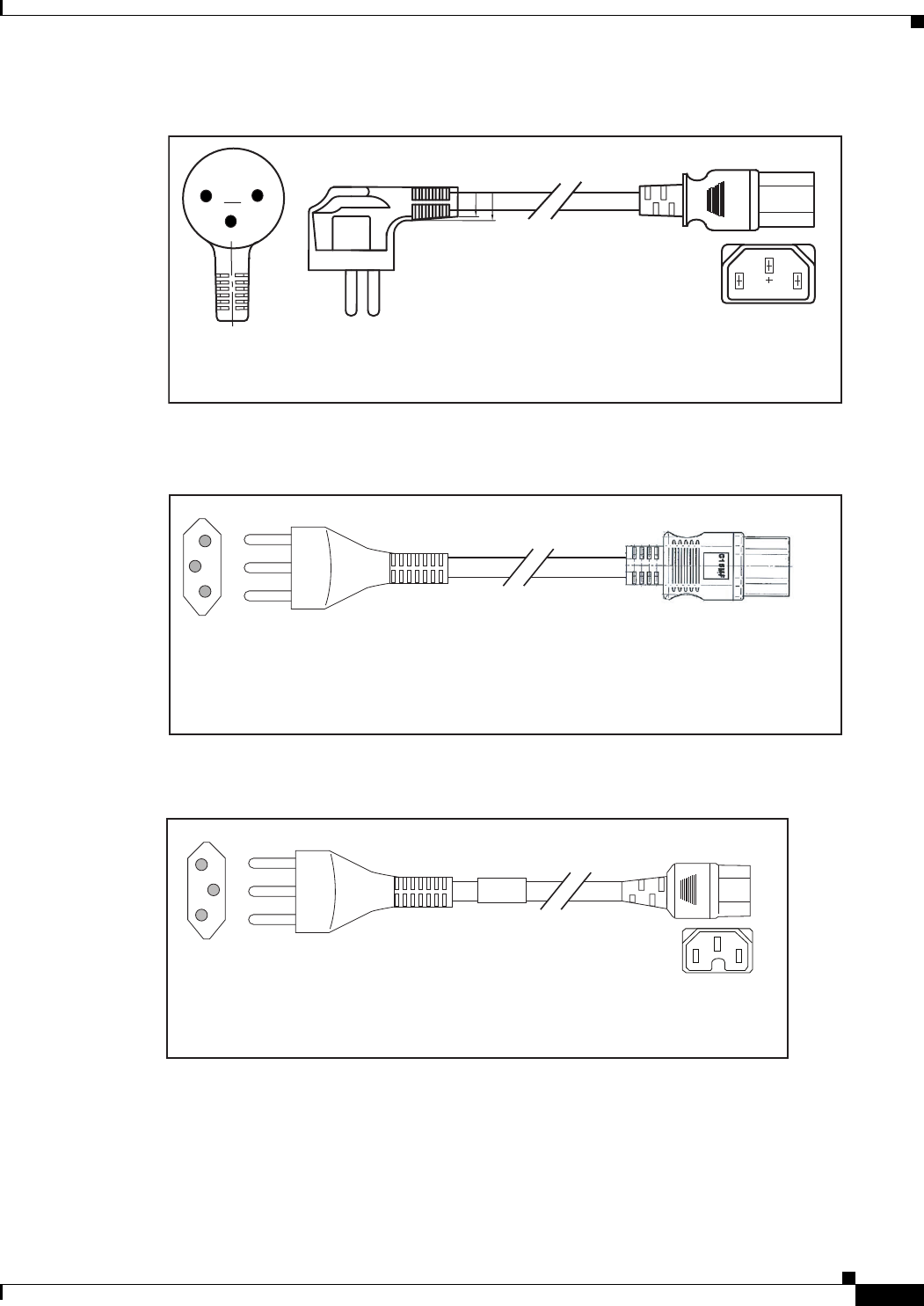
C-5
Cisco Nexus 2000 Series Hardware Installation Guide
Appendix C Cable and Port Specifications
Supported Power Cords and Plugs
Figure C-6 SFS-250V-10A-IS
Figure C-7 CAB-9K10A-IT
Figure C-8 CAB-9K10A-SW
Cordset rating 10A, 250V/500V MAX
(2500 mm)
Plug:
EL 212
(SI-32)
186574
Connector:
EL 701B
(IEC60320/C13)
EL
-212
16A
250V
Plug:
I/3G
(CEI 23-16)
Connector
C15M
(EN60320/C15 )
Cordset rating: 10 A, 250 V
Length: 8 ft 2 in. (2.5 m)
186575
Plug:
MP232-R
Cordset rating: 10 A, 250 V
Length: 8 ft. 2 in (2.5 m)
186578
Connector:
IEC 60320 C15
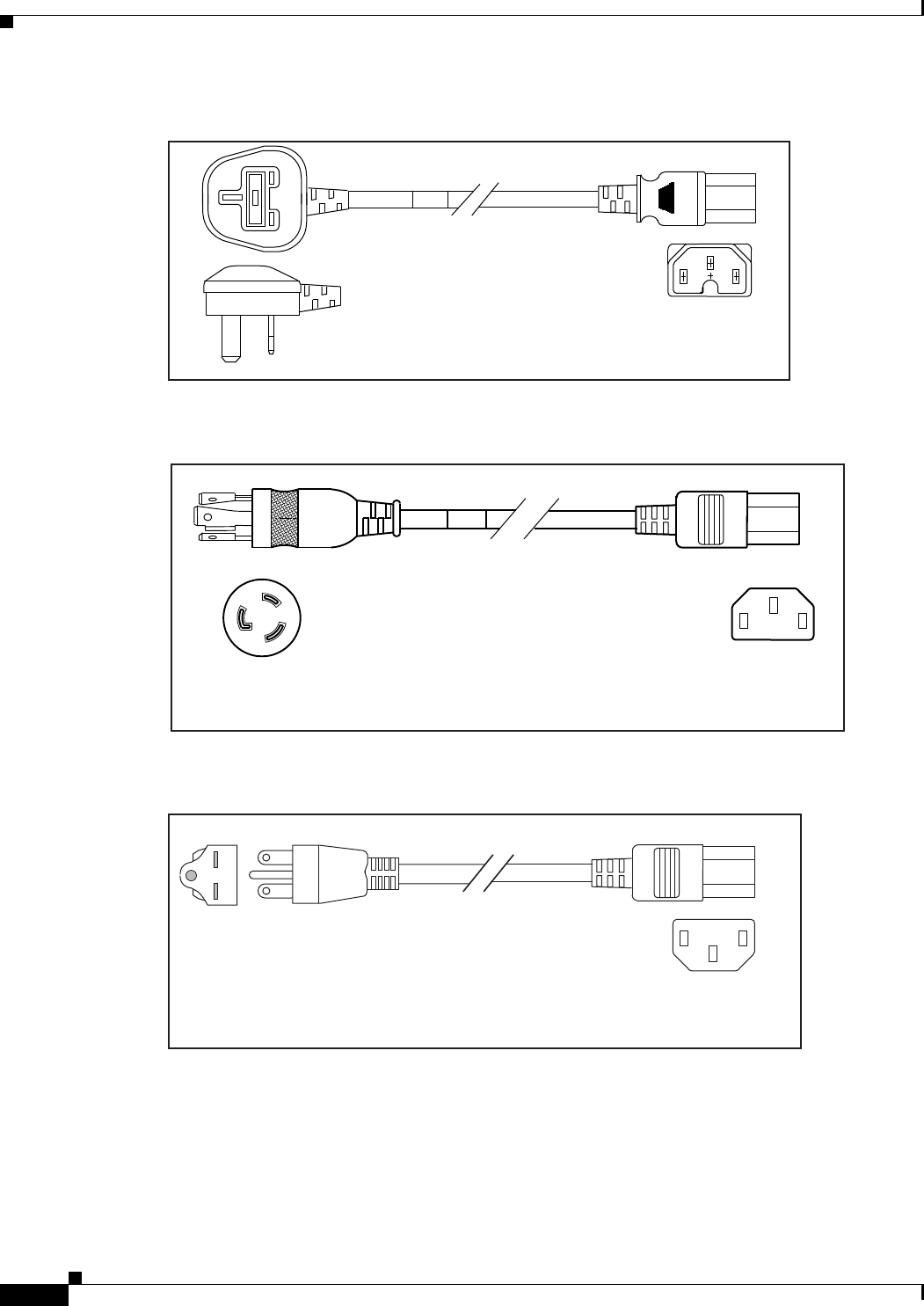
C-6
Cisco Nexus 2000 Series Hardware Installation Guide
Appendix C Cable and Port Specifications
Supported Power Cords and Plugs
Figure C-9 CAB-9K10A-UK
Figure C-10 CAB-AC-250V/13A
Figure C-11 CAB-N5K6A-NA
Plug:
Cordset rating: 10 A, 250 V/500 V MAX
Length: 2500mm
186580
Connector:
EL 701C
(EN 60320/C15)
EL 210
(BS 1363A) 13 AMP fuse
Cordset rating 13A, 250V
(6.6 feet) (79±2m)
Plug:
EL312MoldedTwistlock
(NEMA L6-20)
186568
Connector:
EL 701
(IEC60320/C13)
Cordset rating: 10 A, 250 V
Length: 8.2 ft
186570
Plug: NEMA 6-15P
Connector:
IEC60320/C13
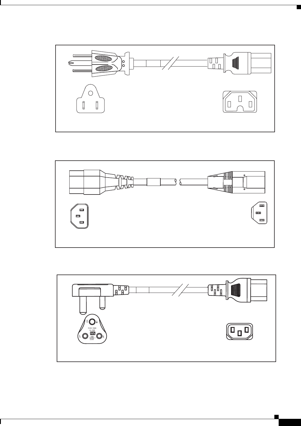
C-7
Cisco Nexus 2000 Series Hardware Installation Guide
Appendix C Cable and Port Specifications
Supported Power Cords and Plugs
Figure C-12 CAB-9K12A-NA
Figure C-13 CAB-C13-CBN
Figure C-14 CAB-IND-10A
Connector:
IEC60320/C15
Cordset rating 13A, 125V
(8.2 feet) (2.5m)
Plug:
NEMA 5-15P
192260
Cordset rating 10A, 250V
(686mm)
Plug:
SS10A
186569
Connector:
HS10S
Connector
EL701B (IEC60320/C13)
Cordset rating 10A, 250V
(8.2 feet) (2.5m)
Plug:
EL 208B (IS 6538-1971)
192259
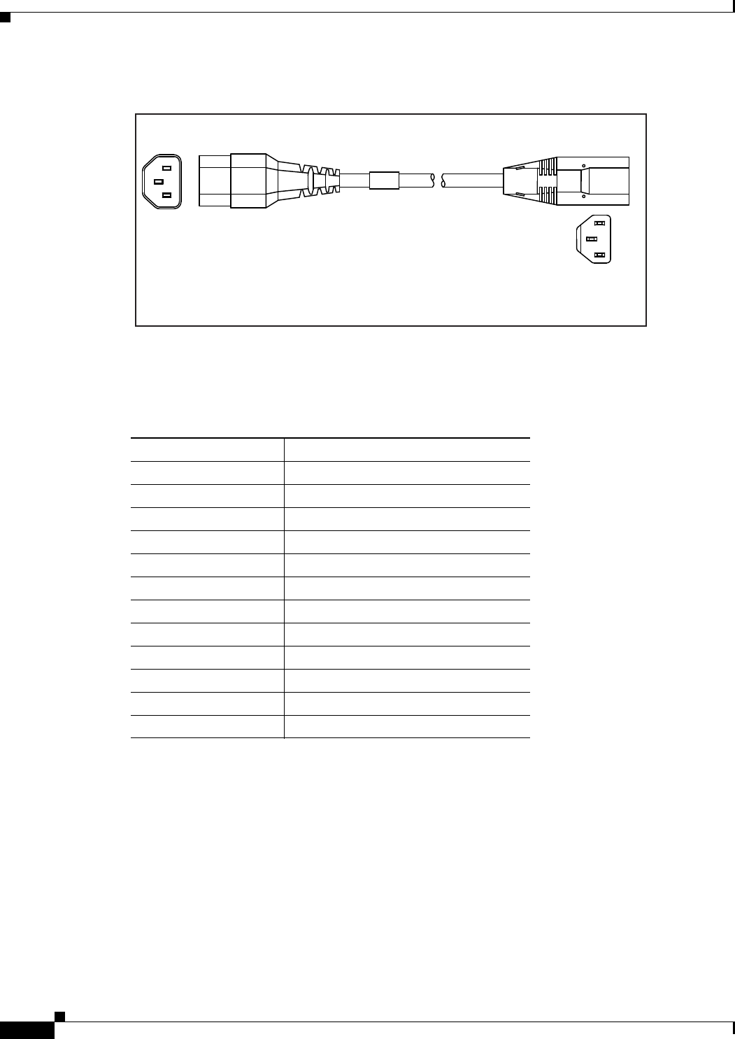
C-8
Cisco Nexus 2000 Series Hardware Installation Guide
Appendix C Cable and Port Specifications
Jumper Power Cord
Figure C-15 CAB-C13-CBN
Table C-2 lists the AC power cords for the Cisco Nexus 2232TM.
Jumper Power Cord
Figure C-16 shows the plug connector on the optional jumper power cord for the Cisco Nexus Fabric
Extender. The plug plugs into the Cisco Nexus Fabric Extender power supply, while the connector plugs
into the receptacle of a power distribution unit for a cabinet.
Connector:
HS 10S
Cordset rating: 10 A,125-250 V
Length: 686 mm
Plug:
SS10A
192532
Table C-2 AC Power Cords for the Cisco Nexus 2232TM
Power Cords Description
CAB-3KX-AC= AC power card for North America
CAB-3KX-AC-AP= AC power card for Australia
CAB-3KX-AC-AR= AC power card for Argentina
CAB-3KX-AC-SW= AC power card for Switzerland
CAB-3KX-AC-UK= AC power card for United Kingdom
CAB-3KX-AC-JP= AC power card for Japan
CAB-3KX-AC-EU= AC power card for Europe
CAB-3KX-AC-IT= AC power card for Italy
CAB-3KX-AC-IN= AC power card for India
CAB-3KX-AC-CN= AC power card for China
CAB-3KX-AC-DN= AC power card for Denmark
CAB-3KX-AC-IS= AC power card for Israel
C-9
Cisco Nexus 2000 Series Hardware Installation Guide
Appendix C Cable and Port Specifications
Jumper Power Cord
Figure C-16 CAB-C13-C14-JMPR, Jumper Power Cord
Cordset rating 10A, 250V
(686mm)
Plug:
SS10A
186569
Connector:
HS10S

C-10
Cisco Nexus 2000 Series Hardware Installation Guide
Appendix C Cable and Port Specifications
Jumper Power Cord

D-1
Cisco Nexus 2000 Series Hardware Installation Guide
APPENDIX
D
Troubleshooting Hardware Components
This chapter describes how to identify and resolve problems that might occur with the hardware
components of the Cisco Nexus 2000 Series Fabric Extender (FEX) or Cisco Nexus 2300 Series FEX. It
includes the following sections:
•Overview, page D-1
•SNMP Traps, page D-1
•Device Hardware Guidelines, page D-2
•Contacting Customer Service, page D-3
Overview
The key to success when troubleshooting the system hardware is to isolate the problem to a specific
system component. The first step is to compare what the system is doing to what it should be doing.
Because a startup problem can usually be attributed to a single component, it is more efficient to isolate
the problem to a subsystem rather than troubleshoot each separate component in the system.
Problems with the initial power up are often caused by a module that is not firmly connected to the
backplane or a power supply that has been disconnected from the power cord connector.
Overheating can also cause problems with the system, though typically only after the system has been
operating for an extended period of time. The most common cause of overheating is the failure of a fan
tray.
SNMP Traps
You can set SNMP traps to monitor fans, power supplies, and temperature settings, or to test a call home
application. Use the following commands to set SNMP traps:
•test pfmtest-SNMP-trap fan
•test pfmtest-SNMP-trap power supply
•test pfmtest-SNMP-trap temp-sensor

D-2
Cisco Nexus 2000 Series Hardware Installation Guide
Appendix D Troubleshooting Hardware Components
Device Hardware Guidelines
Device Hardware Guidelines
Use the recommendations in this section to ensure the proper installation, initialization, and operation
of the device. This section includes the following topics:
•Installation, page D-2
•Initialization, page D-2
•Device Operation, page D-2
Installation
When installing the device, follow these best practices:
•Plan your site configuration and prepare the site before installing the chassis.
•Verify that you have the appropriate power supplies and fan trays for your chassis configuration. For
each chassis, each module must have the same airflow direction. Either all modules have
front-to-back airflow (no black stripe on the front) or all have back-to-front airflow (black stripe on
the front). If you have modules that use different airflow directions in the same chassis, you will see
an error message.
•Install the chassis following the rack and airflow guidelines in this publication.
•Verify that the chassis and DC power supplies are adequately grounded.
Initialization
When the initial system boot is complete, verify the following:
•Power supplies are supplying power to the system.
•Fan trays are operating normally.
•The system software boots successfully. See the Cisco Nexus 2000 Series Fabric Extender Software
Configuration Guide for information about booting the system and initial configuration task.
Device Operation
To ensure proper operation of your device, do the following:
•Make a copy of the running configuration to CompactFlash for a safe backup.
•Always enter the copy running-config startup-config command after you modify the running
configuration and ensure that the system is operating properly.
•Never use the init system command unless you understand that you will lose the running and startup
configuration as well as the files stored on bootflash:.
•Keep backup copies of the running kickstart and the system images on CompactFlash.

D-3
Cisco Nexus 2000 Series Hardware Installation Guide
Appendix D Troubleshooting Hardware Components
Contacting Customer Service
Contacting Customer Service
If you are unable to solve a startup problem after using the troubleshooting suggestions in this chapter,
contact a customer service representative for assistance and additional instructions. Before you call, have
the following information ready to help your service provider assist you as quickly as possible:
•Date that you received the device
•Chassis serial number (located on a label on the right of the rear panel of the chassis)
•Type of software and release number
•Maintenance agreement or warranty information
•Brief description of the problem
•Brief explanation of the steps that you have already taken to isolate and resolve the problem
To contact Cisco Technical Support, go to:
http://www.cisco.com/c/en/us/support/web/tsd-cisco-worldwide-contacts.html.

D-4
Cisco Nexus 2000 Series Hardware Installation Guide
Appendix D Troubleshooting Hardware Components
Contacting Customer Service

E-1
Cisco Nexus 2000 Series Hardware Installation Guide
APPENDIX
E
LEDs
This appendix describes the conditions indicated by the chassis and module LEDs on the Cisco Nexus
Fabric Extenders (FEXs).
This appendix includes the following sections:
•Chassis and Module LEDs for the Cisco Nexus Fabric Extenders, page E-1
•Port LEDs, page E-4
Chassis and Module LEDs for the Cisco Nexus Fabric Extenders
This section includes the following topics:
•Chassis and Module LED Descriptions, page E-2
•Power Supply Status, page E-3

E-2
Cisco Nexus 2000 Series Hardware Installation Guide
Appendix E LEDs
Chassis and Module LEDs for the Cisco Nexus Fabric Extenders
Chassis and Module LED Descriptions
Table E-1 describes the chassis LEDs for the Cisco Nexus Fabric Extenders.
Table E-1 LEDs for the Cisco Nexus Fabric Extenders
Component LED Status Description
Chassis
(port side exhaust
and back)
ID On
(blue)
Identifies the chassis receiving the beacon signal.
Status Solid on
(green)
All diagnostics pass. The module is operational.
Off The module is not receiving power.
On
(amber)
The module is booting or running diagnostics.
An overtemperature condition has occurred. The
temperature threshold has been exceeded by a
small value during environmental monitoring.
Blinking
(amber)
An overtemperature condition has occurred. The
temperature threshold has been exceeded by a
large value during environmental monitoring.
If the module fails during initial reset, the LED
continues to blink and the module does not come
online.
The module has a runtime failure and is brought
offline.
Fan and fan tray
(port side exhaust
of chassis)
Status Solid on
(green)
All diagnostics pass. The module is operational.
Off The module is not receiving power.
Solid on
(amber)
The module is booting or running diagnostics.
Blinking
(amber)
If the module fails during initial reset, the LED
continues to blink and the module does not come
online.
The module has a runtime failure and is brought
offline.
Power supply
(port side exhaust
of chassis)
OK (green) Solid on Power supply is on and okay.
Blinking 12 voltage standby (VSB) is on but the power
supply unit is not powering the other modules.
Off No AC power to the power supply.
FAULT (amber) Solid on Power supply failures, overvoltage, overcurrent,
or overtemperature has occurred.
Blinking AC is present, 12 VSB on, and the power supply
is off.
Off Operating normally.

E-3
Cisco Nexus 2000 Series Hardware Installation Guide
Appendix E LEDs
Chassis and Module LEDs for the Cisco Nexus Fabric Extenders
For a description of the two power supply status, see the “Power Supply Status” section on page E-3.
Power Supply Status
This section describes the power supply LED indicators for the Cisco Nexus Fabric Extenders. Table E-2
describes the status indicated by the Cisco Nexus 2348TQ, Cisco Nexus 2348UPQ, Cisco Nexus
2248TP-ETP, 2232PP, and 2224TP power supply LEDs. Table E-3 describes the status indicated by the
Cisco Nexus 2148T power supply LEDs.
Port LED Indicates LED
status
Off The port is not active or the link is not connected.
Solid on
(green)
The port is active. The link is connected and
operational.
Solid on
(amber)
The module or port is disabled through the CLI
command or the module is initializing.
Blinking
(amber)
The port is faulty and has been disabled.
Table E-1 LEDs for the Cisco Nexus Fabric Extenders
Component LED Status Description
Table E-2 Power Supply LED Indicators for the Cisco Nexus 2348TQ, Cisco Nexus 2348UPQ,
Cisco Nexus 2248TP-ETP, 2232PP, and 2224TP
Condition OK LED Status (Green) FAIL LED Status (Amber)
No AC power to the power supplies Off Off
Power supply failure (includes
overvoltage, overcurrent,
overtemperature, and fan failure)
Off On
Power supply warning events where the
power supply continues to operate
(high temperature, high power, and
slow fan)
Off 1 blinking
AC present /voltage standby (VSB) on,
and power supply unit off
blinking Off
Power supply On and OK On Off
Table E-3 Power Supply LED Indicators for the Cisco Nexus 2148T
Condition INPUT OK LED Status (Green) OUTPUT OK LED Status (Red)
No AC power to the power supplies Off Off
Power supply failure (includes
overvoltage, overcurrent,
overtemperature, and fan failure)
Off On
E-4
Cisco Nexus 2000 Series Hardware Installation Guide
Appendix E LEDs
Port LEDs
Port LEDs
This section includes the following topics:
•Ethernet Port LEDs, page E-4
•Ethernet and Fibre Channel LEDs, page E-4
Ethernet Port LEDs
Table E-4 lists the LED descriptions for the RJ-45 Ethernet port LEDs.
Ethernet and Fibre Channel LEDs
There are 20 to 26 port activity LEDs on the FEX depending on whether the module is a Fibre Channel
or 10-Gigabit Ethernet module. Table E-5 describes the behavior of the port LEDs.
Power supply warning events where the
power supply continues to operate
(high temperature, high power, and
slow fan)
Off Blinking
AC present and power supply unit off Blinking Off
Power supply On and OK On Off
Table E-3 Power Supply LED Indicators for the Cisco Nexus 2148T (continued)
Condition INPUT OK LED Status (Green) OUTPUT OK LED Status (Red)
Table E-4 Ethernet Port LED Descriptions
LED Status Description
Left Off No link
Solid green Physical link
Right Off No activity
Blinking green Activity
Table E-5 Port-Level LEDs
Link State LED State Notes
Link Down OFF —
POST failed on port AMBER blinking yellow —

E-5
Cisco Nexus 2000 Series Hardware Installation Guide
Appendix E LEDs
Port LEDs
Administrative disabled AMBER_ON Depending on the product you look at, the
LED could be off, or solid amber
Link Up,
port in STP forwarding
state
GREEN_ON Blinks based on network activity
Table E-5 Port-Level LEDs
Link State LED State Notes

E-6
Cisco Nexus 2000 Series Hardware Installation Guide
Appendix E LEDs
Port LEDs

F-7
Cisco Nexus 2000 Series Hardware Installation Guide
APPENDIX
F
Accessory Kit
This appendix lists the accessory kit contents for the Cisco Nexus Fabric Extenders (FEXs). This
appendix includes the following sections:
•Accessory Kit for Cisco Nexus 2300 Series FEXs, page F-7
•Accessory Kit for Cisco Nexus 2248TP-E, 2224TP, 2232PP, 2248TP, 2232TM, and 2148T, page F-8
Accessory Kit for Cisco Nexus 2300 Series FEXs
Accessory kits for the Cisco Nexus 2300 Series FEXs contain the following items:
•2 slider rails
•1 rack-mount guide
•1 rack-mount bracket
•10 M4 x 0.7 x 7-mm Phillips countersunk screws
•1 ground lug kit
•1 ESD wrist strap
Table F-2 provides ordering information for the Cisco Nexus 2300 Series FEXs.
Note Additional parts can be ordered from your customer service representative.
Table F-1 Accessory Kit Information for the Cisco Nexus 2300 Series Fabric Extenders
Accessory Kit Details
N2300-ACC-KIT Cisco Nexus 2300 FEX accessory kit
N2300-ACC-KIT= Cisco Nexus 2300 FEX accessory kit, spare

F-8
Cisco Nexus 2000 Series Hardware Installation Guide
Appendix F Accessory Kit
Accessory Kit for Cisco Nexus 2248TP-E, 2224TP, 2232PP, 2248TP, 2232TM, and 2148T
Accessory Kit for Cisco Nexus 2248TP-E, 2224TP, 2232PP,
2248TP, 2232TM, and 2148T
Accessory kits for the Cisco Nexus 2148T, 2224TP, 2232PP, 2248TP, 2248TP-E, and 2232TM FEXs
contain the following items:
•2 slider rails
•2 rack-mount guides
•2 rack-mount brackets
•16 M4 x 0.7 x 8-mm Phillips countersunk screws
•1 ground lug kit
•1 ESD wrist strap
Table F-2 provides ordering information for the Cisco Nexus 2148T, 2224TP, 2232PP, 2248TP-ETP, and
2232TM FEXs.
Note Additional parts can be ordered from your customer service representative.
Table F-2 Accessory Kit Information for the Cisco Nexus 2148T, 2224TP, 2232PP, 2248TP,
2248TP-E, and 2232TM Fabric Extenders
Accessory Kit Details
N2K-C2148T-ACC Cisco Nexus 2000 FEX 1GE accessory kit, spare
N2200-ACC-KIT Cisco Nexus 2200 FEX accessory kit, spare

G-1
Cisco Nexus 2000 Series Hardware Installation Guide
APPENDIX
G
Site Preparation and Maintenance Records
This appendix includes the following records to use when installing the Cisco Nexus Fabric Extender
(FEX):
•Site Preparation Checklist, page G-1
•Contact and Site Information, page G-3
•Chassis and Module Information, page G-3
Note For information about how to query the device for configuration information, see the Cisco Nexus 2000
Switch Configuration Guide.
Site Preparation Checklist
Planning the location and layout of your equipment rack or wiring closet is essential for successful
device operation, ventilation, and accessibility. Table G-1 lists the site planning tasks that we
recommend completing before installing the Cisco Nexus FEX.
Consider heat dissipation when sizing the air-conditioning requirements for an installation. See
Table B-2 on page B-6 for the environmental requirements and the “Power Specifications” section on
page B-1 for power and heat ratings.

G-2
Cisco Nexus 2000 Series Hardware Installation Guide
Appendix G Site Preparation and Maintenance Records
Site Preparation Checklist
Table G-1 Site Planning Checklist
Task No. Planning Activity Verified By Time Date
1 Space evaluation:
•Space and layout
•Floor covering
•Impact and vibration
•Lighting
•Maintenance access
2 Environmental evaluation:
•Ambient temperature
•Humidity
•Altitude
•Atmospheric contamination
•Air flow
3 Power evaluation:
•Input power type
•Power receptacles1
•Receptacle proximity to the
equipment
•Dedicated circuit for power supply
•Dedicated (separate) circuits for
redundant power supplies
•UPS2 for power failures
1. Verify that the power supply installed in the chassis has a dedicated AC source circuit.
2. UPS = uninterruptible power supply.
4 Grounding evaluation:
•Circuit breaker size
•CO ground (AC-powered systems)
5 Cable and interface equipment
evaluation:
•Cable type
•Connector type
•Cable distance limitations
•Interface equipment (transceivers)
6EMI
3 evaluation:
•Distance limitations for signaling
•Site wiring
•RFI4 levels

G-3
Cisco Nexus 2000 Series Hardware Installation Guide
Appendix G Site Preparation and Maintenance Records
Contact and Site Information
Contact and Site Information
Use the following worksheet (see Table G-2) to record contact and site information.
Chassis and Module Information
Use the following worksheet (see Table G-3) to record information about the chassis.
Contract Number_______________________________________________
Chassis Serial Number___________________________________________
Product Number________________________________________________
3. EMI = electromagnetic interference.
4. RFI = radio frequency interference.
Table G-2 Contact and Site Information
Contact person
Contact phone
Contact e-mail
Building/site name
Data center location
Floor location
Address (line 1)
Address (line 2)
City
State
Zip code
Country

G-4
Cisco Nexus 2000 Series Hardware Installation Guide
Appendix G Site Preparation and Maintenance Records
Chassis and Module Information
Table G-3 Network-Related Information
Device IP address
Device IP netmask
Host Name
Domain name
IP broadcast address
Gateway/router address
DNS address
Modem telephone number
