Chiayo Electronics Co AL30 AEROLINK User Manual
Chiayo Electronics Co Ltd AEROLINK Users Manual
Users Manual

Operating Manual
AL 3.0

AUX OUT
DC IN
12V
LINE OUT
13 2
654 7
AL 3.0 Aerolink
Bluetooth® Receiver
Thank you for purchasing the Aerolink by Fitness Audio. This product is easy to install by
anyone one who is familiar with setting up sound systems.
1. Powering It Up.
The Aerolink can be powered from any 12V500mA already in use in the audio system like
those that power the Wireless Mic Receiver using the DC “Y” Cable supplied. Alternatively, if
you purchased the unit with an optional 12V DC Power Supply then please plug that into a
GPO and DC connector into the Power In socket (1).
2. Connecting to a Mixer.
Connect using either the Stereo (TRS) Line Out Jack (3) or the 2 RCA sockets(2) to your mix-
er’s matching Line Input sockets. A standard 2RCA to 2RCA Cable is provided.
3. Turn it on and linking up.
When you turn it on, the blue Power-on light in the switch illuminates and the 2 blue LEDs
will start flashing once you have pushed the Blue LINK button (6). The first, “SCAN” LED(4) is
searching for a smartphone or player to pair with, so, open your smartphone, go to Settings,
select Bluetooth, turn Bluetooth on and watch it search for devices. After a few seconds
the words Aerolink will appear and Not Connected will change to Connected and the SCAN
LED will stop flashing. The second, “LOCK LED(5) will go solid confirming the link is good. Go
to your music file on the device and select the Playlist you want to use and press Play. If the
sound system is turned on and the Aerolink has been selected then you will hear the music
so set the volume and you are up and running with Aerolink. Please note that the Volume
Control (7) on the front Panel of the Aerolink is a “Turn Down” one so should always be on
MAX unless a better cleaner sound with the Mixer or Amp input you are using is achieved
with it set at the 12 o’clock position.
4. Re-setting the Link
Once you take the linked device out of the range of the receiver (around 8 meters or 25 feet)
you will need to re-scan and connect again. Press the Blue Button to break a link and to start
a new linking process again.
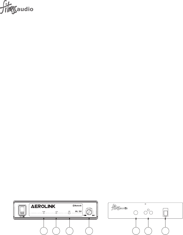
Key To Illustration:
1. DC Input
2. RCA Outputs
3. ¼” Stereo Jack Output
4. SCAN LED
5. LOCK LED
6. LINK button
7. Volume Control

This device complies with Part 15 of the FCC Rules. Operation is
subject to the following two conditions:
(1) This device may not cause harmful interference, and
(2) This device must accept any interference received, including
interference that may cause undesired operation.
Fitness Audio products are distributed worldwide by Fitness Audio Network. They are
manufacturing defects by a 12 month warranty commencing at the date of purchase.
__________
Warranty information for service claims.
(Please retain for your records.)
This product was purchased by:
(Business Name) ............................................... .............................
on (date) . . / . . / . . from (Supplier) .............................. .............................
of (address) .................................................... .............................
Serial Number.................................................. .............................
Federal Communication Commission Interference Statement
This equipment has been tested and found to comply with the limits for a Class B digital device, pursuant to Part 15 of
the FCC Rules. These limits are designed to provide reasonable protection against harmful interference in a residential
installation. This equipment generates, uses and can radiate radio frequency energy and, if not installed and used in
accordance with the instructions, may cause harmful interference to radio communications. However, there is no
guarantee that interference will not occur in a particular installation. If this equipment does cause harmful interference
to radio or television reception, which can be determined by turning the equipment o and on, the user is encouraged
to try to correct the interference by one of the following measures:
. Reorient or relocate the receiving antenna.
. Increase the separation between the equipment and receiver.
. Connect the equipment into an outlet on a circuit dierent from that to which the receiver is connected.
. Consult the dealer or an experienced radio/TV technician for help.
FCC Caution: To assure continued compliance, any changes or modications not expressly approved by the party
responsible for compliance could void the user's authority to operate this equipment. (Example - use only shielded
interface cables when connecting to computer or peripheral devices).
FCC Radiation Exposure Statement
This equipment complies with FCC RF radiation exposure limits set forth for an uncontrolled environment. This
equipment should be installed and operated with a minimum distance of 20 centimeters between the radiator and
your body.
This transmitter must not be co-located or operating in conjunction with any other antenna or transmitter.
WARNING
Do not remove lids
No user serviceable parts inside
Do not place liquid containers on unit
Do not expose to moisture or rain
Fitness Audio Network P/L
PO Box 321
Alexandria NSW 1435
AUSTRALIA
www.fitnessaudio.net.au
12I2231