Chiayo Electronics Co CY2005-TX Wireless Microphone Transmitter User Manual
Chiayo Electronics Co Ltd Wireless Microphone Transmitter Users Manual
Users Manual
Federal Communication Commission Interference Statement
This equipment has been tested and found to comply with the limits for a Class B digital device, pursuant
to Part 15 of the FCC Rules .These limits are designed to provide reasonable protection against harmful
interference in a residential installation.
This equipment generates, uses and can radiated radio frequency energy and, if not installed and used
in accordance with the instructions, may cause harmful interference to radio communications. However,
there is no guarantee that interference will not occur in a particular installation. If this equipment does
cause harmful interference to radio or television reception, which can be determined by turning the
equipment off and on, the user is encouraged to try to correct the interference by one of the following
measures:
Reorient or relocate the receiving antenna.
Increase the separation between the equipment and receiver.
Connect the equipment into an outlet on a circuit different from that to which the receiver is
connected.
Consult the dealer or an experienced radio/TV technician for help.
FCC Caution :
To assure continued compliance,any changes or modifications not expressly approved by the party
responsible for compliance could void the user's authority to operate this equipment.(example-use only
shielded interface cables when connecting to computer or peripheral devices).
This device complies with Part 15 of the FCC Rules. Operation is subject to the following two conditions:
(1)This device may not cause harmful interference, and (2)this device must accept any interference
received, including interference that may cause undesired operation.
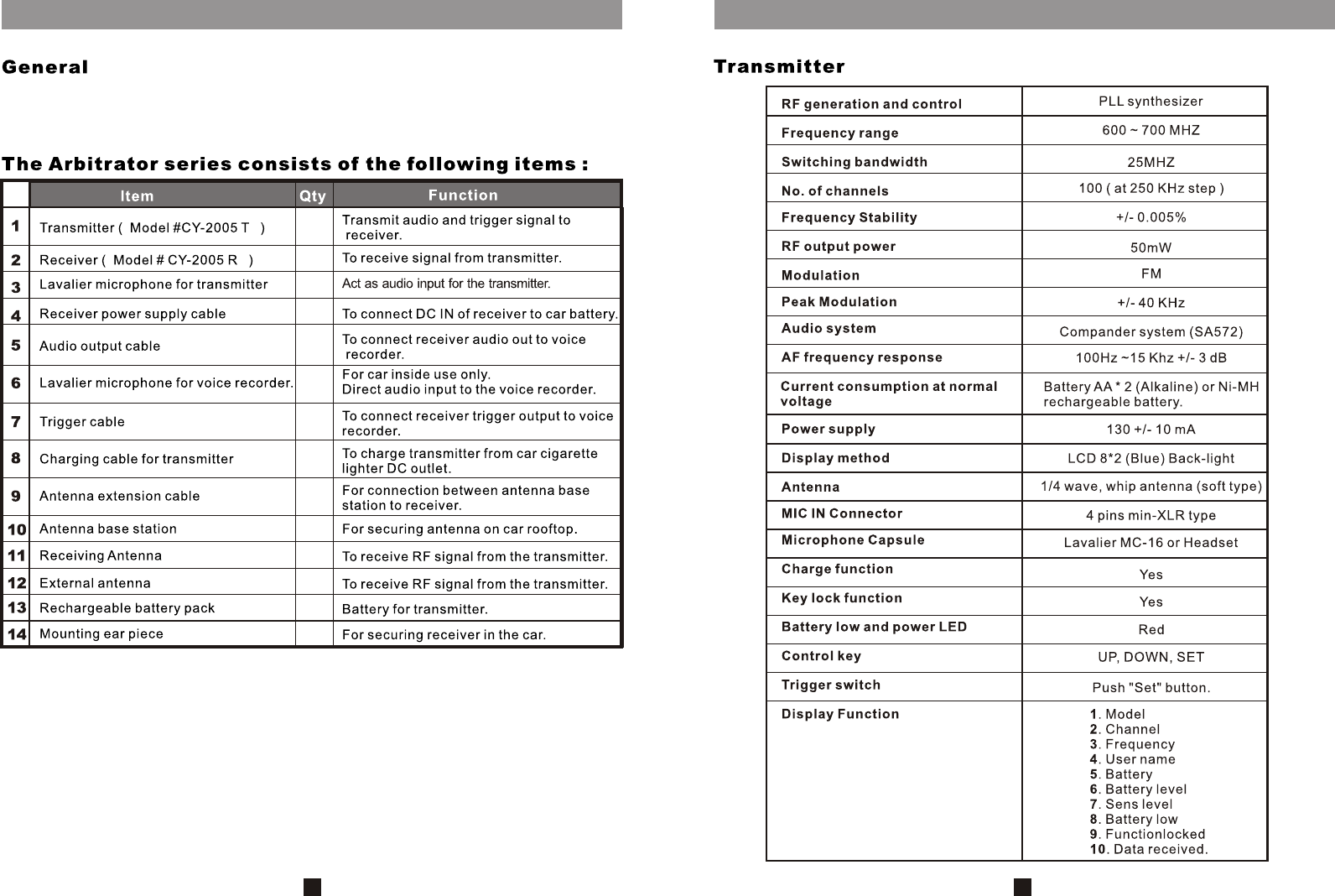
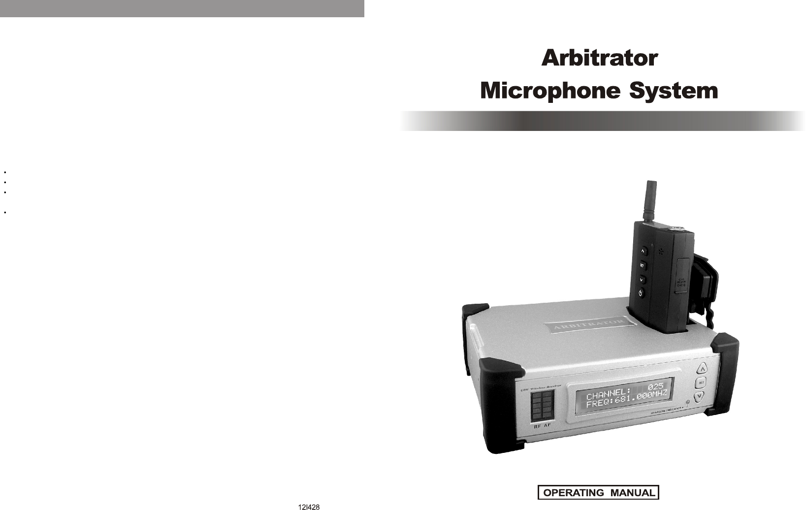
Thank you for purchasing microphone system this state-of-art, Arbitrator series , which consists
of a transmitter and receiver. The operating frequency of this series is in UHF band. To have a
trouble free operation, please read this owner's manual thoroughly.
1
1
1
1
1
1
1
1
1
2
2
2
2
2
1
14
1 2 3 4
5
6
7
89
12 13 14
15
16
10 11
2
Specifications
13
12
3
4
5
6
7
8
910 11 12 13 14
15
3
In this case, or buttons act as rolling up or down the alphanumeric characters,
not the pages.
12
Press SET for a few seconds, cursor will flash at the ON / OFF wording. Use or
to change the status. Press SET again for a few seconds will store the change into the
memory.
When System Lock is ON, the power switch and channel change functions will be defeated. To
unlock, repeat the above procedure and change it to System Lock OFF status to return to normal
function.
Press SET for a few seconds, cursor will flash at the CH No.. Use or to change
the channel no. from 001 to 100. After the desired channel has been selected, press
SET again for a few seconds will store the change into the memory. Please be
reminded that for the system to work the channel selected at the transmitter must be
the same as that of the receiver.
When system is in " Lock " mode, SET switch will become a MUTE SWITCH.
Press MUTE SWITCH 2 times quickly, system will enter into MUTE-ON status.
Press MUTE SWITCH another time, system will become MUTE-OFF.
675.000M
BATTERY
N i-MH
UHF
CH: 001
CY-2005T
675.000
SYSTEM
LOCK ON
USER NAM
CH:001
nd
2.The 2 method to start the Auto Scan function is to place transmitter into the drop
in charging data port ( 11 ) on top of the receiver, the charging indicator on the
receiver front panel will start flashing and receiver auto scan function will start
automatically. The channel digit will roll through all the 100 channels until a clean
channel has been selected. When auto scan is completed, the following page will
appear :
cradle
11
Which indicate the selected data ( including user name ) has been successfully
transferred to the transmitter. At this moment RF level indicator in receiver front panel
will light up indicates receiver has received the RF signal from the transmitter.
When voice is spoken into either the built-in condenser or lavalier microphone, AF
indicator in receiver front panel will flash.
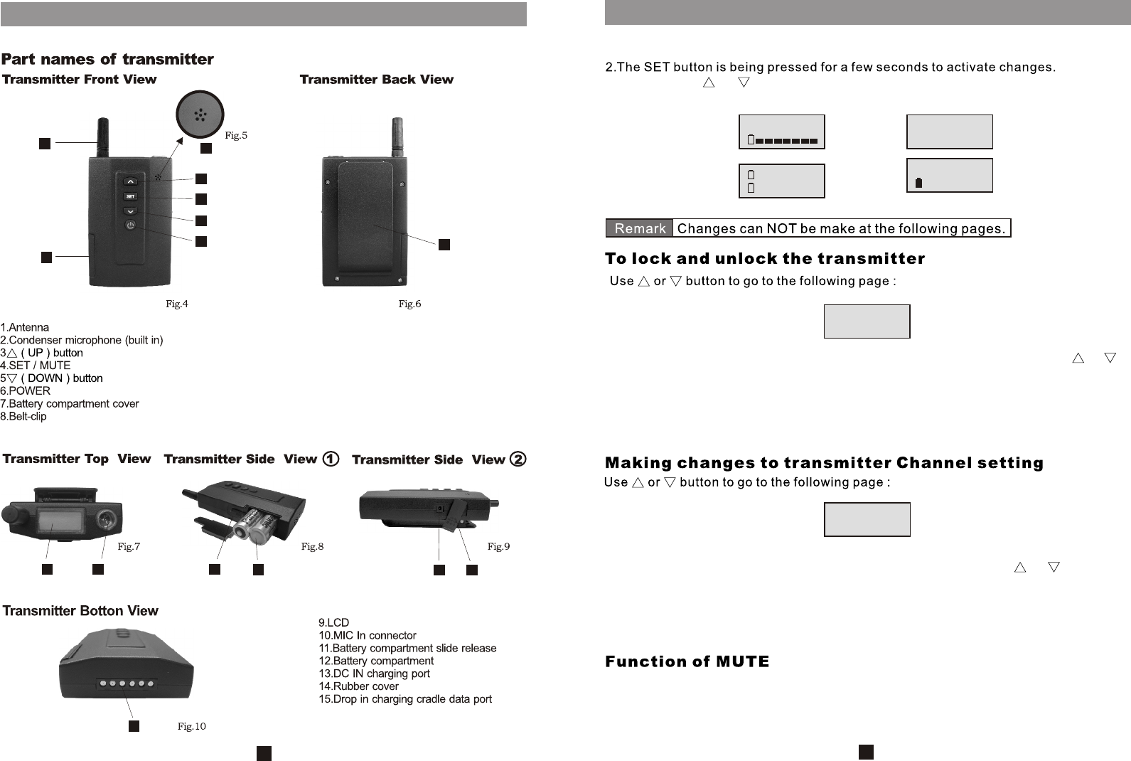
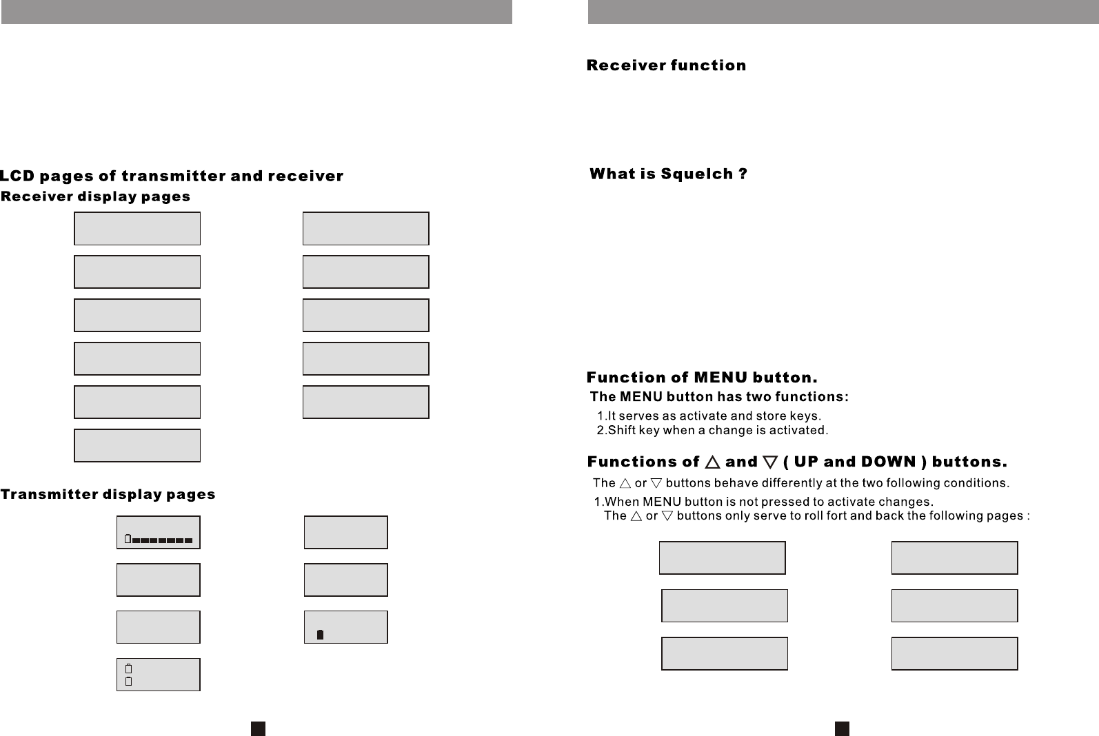
The function of the transmitter is to transmit the audio modulated signal to the
receiver via radio link. In this case through the UHF band. Voice could be picked up
either through the built-in condenser microphone of the lavalier microphone worn by
the user.
Accessories
4
FINISH SCANNING
DUMP DATA TO TX
UHF
CY-2005T
USER NAM
CH: 001
CH: 001
675.000
675.000M
SYSTEM
LOCK ON
BATTERY
N i-MH
5
B
AA
B
USER NAME can only be modified in this page, not in the ARBITRATOR / USER
NAME page.
At first time power on, there is no specific User Name stored. If user thinks that it is
necessary to give it a User Name to the ARBITRATOR series, please follow the
instruction below to add it in.
10
st
It is NOT possible to change the 1 line which shows CHANNEL No., To make
changes to the USER NAME setting, press MENU button for a few seconds until
st nd
cursor flashes at 1 alphabet in the 2 display line, use or button to roll through
the alphanumeric characters. When the desired level has been selected, press MENU
once to move the cursor one step forward, use or button to roll through the
alphanumeric characters. Repeat this sequence until all desired characters have
been selected. Press MENU for a few seconds again to store the selection into the
memory. The stop flashing of the cursor indicates successful storage. Both
ARBITRATOR / USER NAME and CHANNEL / USER NAME pages will show the newly
programmed USER NAME.
The receiver Auto Scan can work in two different ways, with or without the transmitter.
To start the Auto Scan function, press MENU button for a few seconds until Auto
Scanning start. The channel digit will roll through all the 100 channels until a clean
channel has been selected. When auto scan is completed, the following page will
appear :
CHANNEL: 025
USER NAME
ARBITRATOR
USER NAME IN
AUTO SCANNING
CHANNEL : 025
FINISH SCANNING
DUMP DATA TO TX
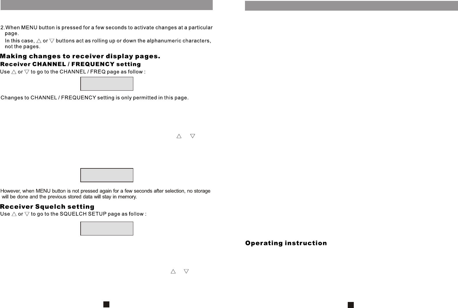
The Arbitrator has 100 factory preset channels available for selection. At first time
power on, the CHANNEL No. shown is the factory preset channel. If this channel is
not suitable at user's site, please change it to the desired one.
To make changes to the channel setting, press MENU button for a few seconds until
cursor flashes at the channel digit. To select a particular channel, use or button
to roll through channel 001 to 100. When the desired channel has been selected,
press MENU for a few seconds again to store the change into the memory. The stop
flashing of the cursor indicates successful storage. Both the CHANNEL / FREQ and
ARBITRATOR / CHANNEL pages will show the newly programmed channel number.
The Arbitrator has 10 factory preset Squelch levels available for selection. At first
time power on, the squelch level shown is the factory preset level. If this level is not
suitable at user's site, please change it to the desired one.
To make changes to the squelch level setting, press MENU button for a few seconds
until cursor flashes at the level digit. To select a particular level, use or button to
roll through level 01 to 10. When the desired level has been selected, press MENU
for a few seconds again to store the selection into the memory. The stop flashing of
the cursor indicates successful storage. When MENU button is not pressed after
selection, no storage will be done and the previous stored data will stay in memory.
96
The Arbitrator series of radio microphone is intended to be installed in the car of
security personnel.
The receiver should be installed inside the car near the driver or in the trunk of the car.
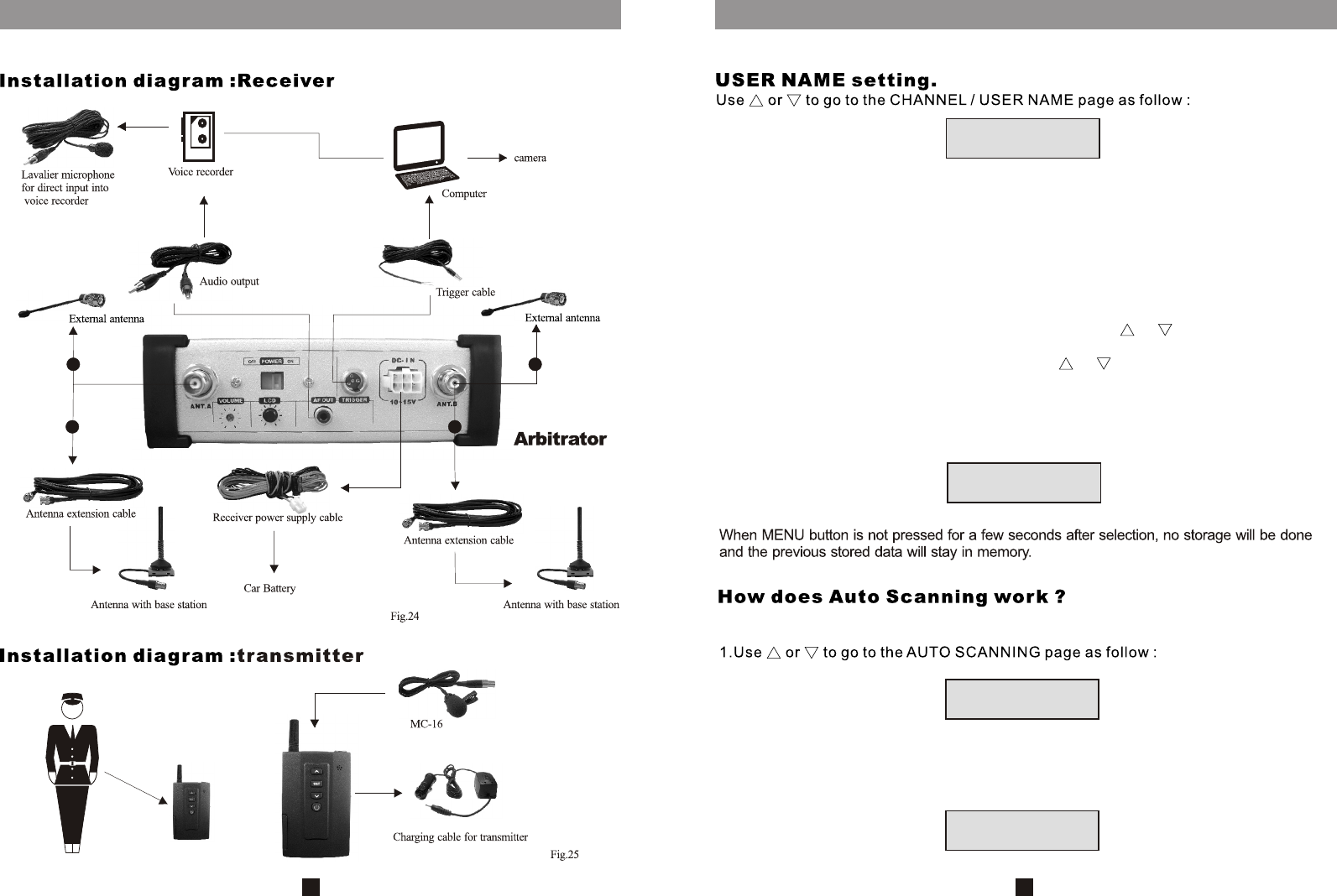
Mounting brackets ( 23 ) are provided for fixing the receiver securely to the car. The
power supply for the receiver comes from the car battery via the power supply cable (
12 ). Two remote antennas ( 20 ) are to be placed at the car rooftop and connected to
the receiver via the antenna extension cables ( 15 ). Antenna base stations ( 18 ) are
available for fixing the antenna to the car.
When remote antennas are not needed, two other antennas ( 22 ) are available to be
fixed directly on the receiver.
The trigger output ( 13 ) from the receiver is connected to the laptop computer via the
trigger cable (16 ). Once a trigger signal is received from the transmitter, the
computer will switch on the video camera as well as the voice recorder.
Audio output ( 11 ) of the receiver is connected to the voice recorder via an audio
cable ( 13 ) for recording purposes.
There is another lavalier microphone (14 ) available to be connected directly to the
voice recorder and this is to be installed inside the car.
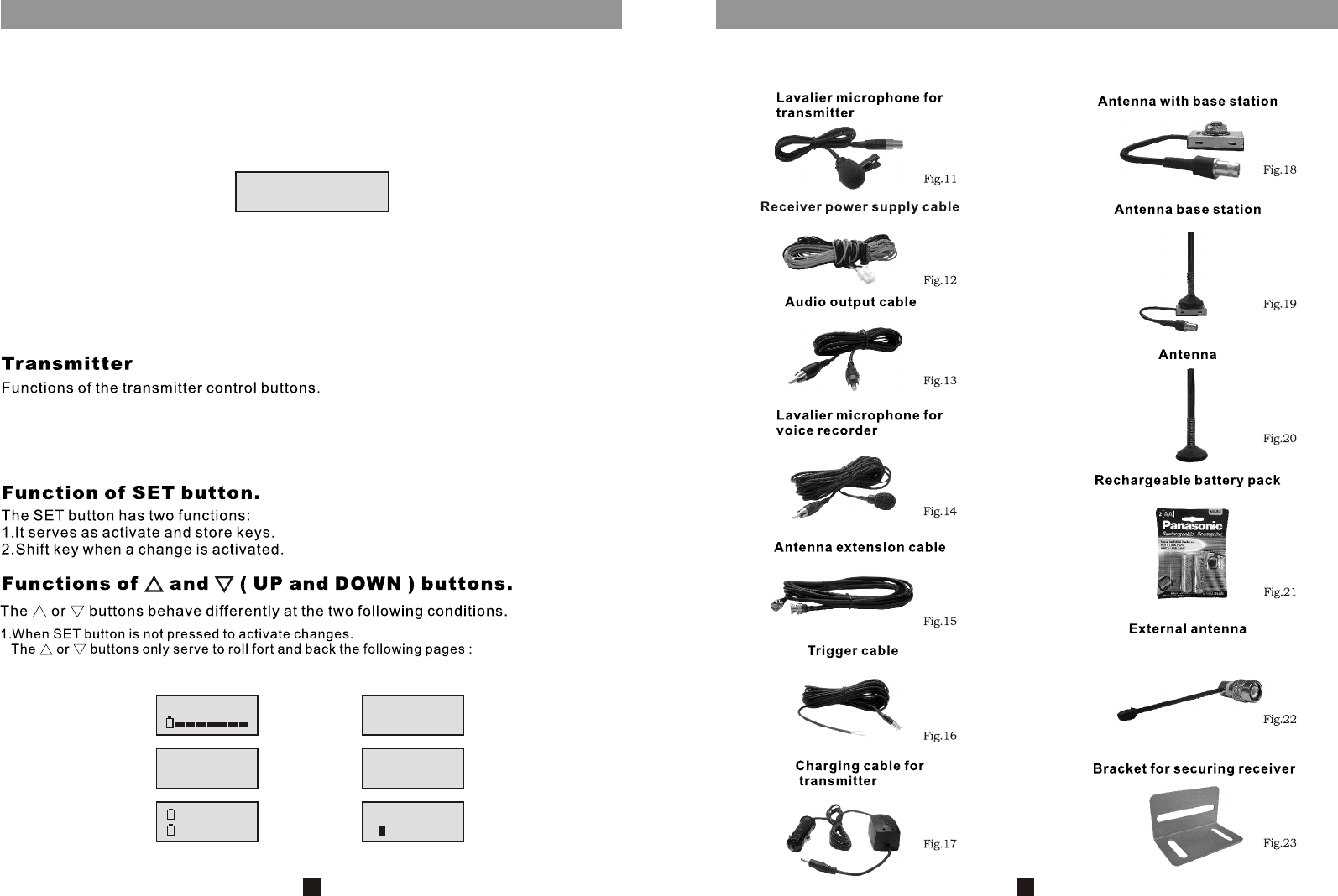
As for the transmitter,install the lavalier microphone for transmitter ( 11 ) into the
transmitter MIC IN socket ( 10 ). Belt clip is available on the back of the transmitter for
wearing it on the belt.
The power supply of the transmitter comes from two AA type batteries. Please use the
Panasonis rechargeable battery pack ( 21 ) supplied. When inserting the battery,
please take extra care to insert it according to the correct polarity of the battery.
When the receiver is installed in the trunk of the car and charging of the transmitter
battery is not possible via the receiver charging port, please use the supplied
charging cable for transmitter ( 17 ) and charge the batteries from the cigarette lighter
outlet of the car.
The Arbitrator series is a radio product. It consists of a transmitter and a compatible
receiver. To operate the system, one must first switch on the receiver and the
corresponding transmitter. The power switch ( 12 ) of the receiver is situated at the
rear panel of the receiver. After switching on, slot in the transmitter into the receiver
charging cradle data port ( 16 ). Auto scan function will start automatically and the
selected clean channeled will then be transferred to the transmitter.
CHANNEL: 025
FREQ:681.000MHZ
ARBITRATOR
CHANNEL : 025
SQUELCH SETUP
LEVEL : 01
However, when the receiver is placed at the trunk of the car, auto scan will not work
this way and no data transfer will happen. In such event, the user must manually set
the transmitter channel to match with the receiver channel.
When transmitter and receiver have the same channel switched on, the RF indicator
will light up. When voice is spoken into the microphone of the transmitter, AF
indicator LED will also light up.
7
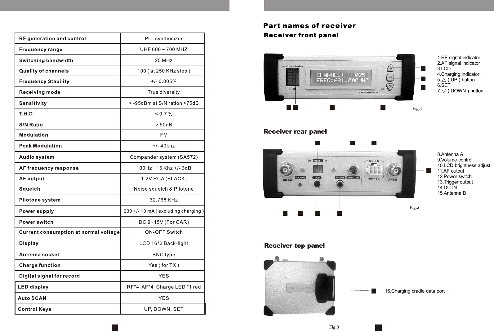
The function of the Arbitrator receiver CY-2005R is to capture the RF signal radiated
from the Arbitrator transmitter CY-2005T. The Arbitrator CY-2005R is a true diversity
receiver. Thus two antennas are needed. The demodulated audio signal from the
receiver is then fed into the voice recorder. The voice recorder will only start to work
when it receives the trigger signal from the Arbitrator transmitter CY-2005T.
Squelch is to mute or silence the audio output of the receiver in the absence of the
desired radio signal. When the desired signal is lost, due to dropout, excessive
distance or loss of transmitter power, the receiver may pick up background radio
noise.
The squelch circuit here is an audio switch controlled by the radio signal level using a
manually adjustable level. When the received signal strength falls below this level the
output of the receiver is then muted. Ideally, the SQ level should be set just above the
background noise level or at the point where the desired signal is becoming too noisy.
Higher SQ level setting requires higher received signal strength. Since received
signal strength decreases as transmission distance increases, higher SQ level
setting will decrease the operating range of the system.
8
CHANNEL: 025
FREQ:681.000MHZ
SQUELCH SETUP
LEVEL : 01
AUTO SCANNING
CHANNEL : 025
ARBITRATOR
USER NAME IN
CHANNEL : 025
RECORD POWER ON
ARBITRATOR
CHANNEL : 025
AUTO SCANNING
CHANNEL : 070
AUTO SCANNING
CHANNEL : 035
AUTO SCANNING
CHANNEL : 057
FINISH SCANNING
DUMP DATA TO TX
CHANNEL : 025
USER NAME
UHF
CY-2005T
USER NAM
CH: 001
CH: 001
675.000
BATTERY
N i-MH
675.000M
SYSTEM
LOCK ON
SYSTEM
LOCK OFF
AUTO SCANNING
CHANNEL : 025
ARBITRATOR
USER NAME IN
ARBITRATOR
CHANNEL : 025
CHANNEL : 025
USER NAME
CHANNEL: 025
FREQ:681.000MHZ
SQUELCH SETUP
LEVEL : 01