Chiayo Electronics Co SM-6000 Wireless Microphone Transmitter User Manual
Chiayo Electronics Co Ltd Wireless Microphone Transmitter Users Manual
Users Manual
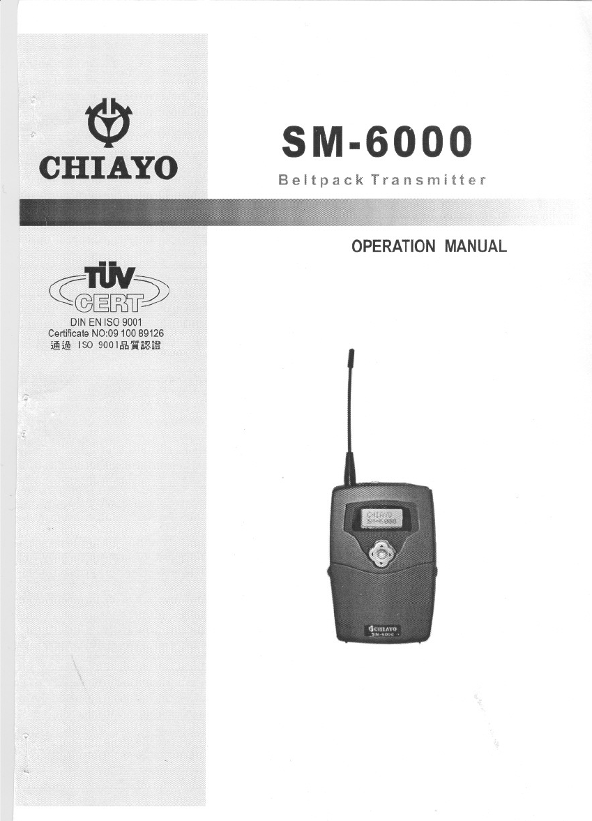
SM-6000
Beltpack Transmitter
OPERATIONMANUAL
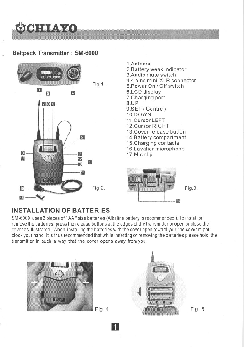
BeltpackTransmitter: SM-6000
Fig.1 .
l~
fJlIlliI
D
/(iJ
II
iIJ
Fig.2.
1.Antenna
2.Battery weak indicator
3.Audio mute switch
4.4 pins mini-XLR connector
5.Power On / Off switch
6.LCD display
7.Charging port
8.UP
9.SET ( Centre)
1a.DOWN
11.Cursor LEFT
12.Cursor RIGHT
13.Cover release button
14.Battery compartment
15.Charging contacts
16.Lavalier microphone
17.Mic clip
Fig.3.
II
INSTAllATION OF BATTERIES
8M-6000 uses2 piecesof" AA" size batteries (Alkaline battery is recommended). Toinstall or
removethebatteries, press the release buttonsat the edges of thetransmitter to open or closethe
coveras illustrated. When installing the batterieswith the cover opentoward you, the cover might
block your hand. It is thus recommendedthat while inserting or removingthe batteries pleasehold the
transmitter in such a way that the cover opens away from you.
Fig.4
~
Fig.5
n
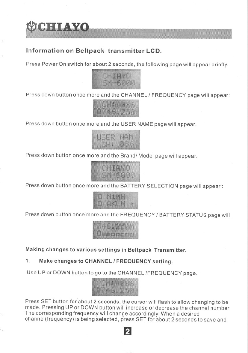
Information on Beltpack transmitter LCD.
Press Power On switch for about 2 seconds, the following page will appear briefly.
Press down button once more and the CHANNEL IFREQUENCY page will appear:
Press down button once more and the USER NAME page will appear.
Press down button once more and the Brandl Model page will appear.
Press down button once more and the BATTERY SELECTION page will appear:
Press down button once more and the FREQUENCY IBATTERY STATUS page will
Making changes to various settings in Beltpack Transmitter.
1. Make changes to CHANNEL IFREQUENCY setting.
Use UP or DOWN button to go to the CHANNEL {FREQUENCY page.
Press SET button for about 2 seconds, the cursor will flash to allow changing to be
made. Pressing UP or DOWN button will increase or decrease the channel number.
The corresponding frequency will change accordingly. When a desired
channel(frequency) is being selected, press SET for about 2 seconds to save and
F1
Remark: When changing transmitter frequencies, care should be taken
to avoid causing interference to other channels Iusers.
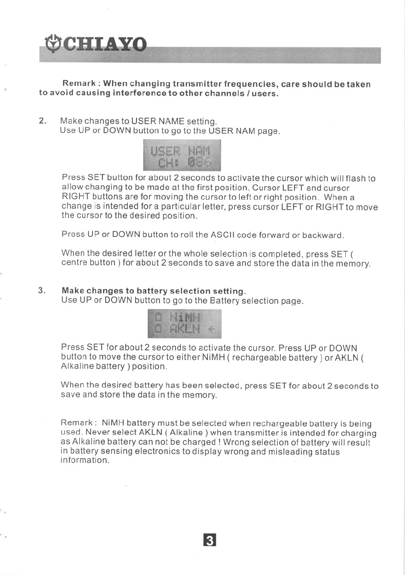
2. Make changes to USER NAME setting.
Use UP or DOWN button to go to the USER NAM page.
Press SET button for about 2 seconds to activate the cursor which willflash to
allow changing to be made at the first position. Cursor LEFTand cursor
RIGHTbuttons are for moving the cursor to left or right position. When a
change is intended for a particular letter, press cursor LEFTor RIGHTto move
the cursor to the desired position.
Press UP or DOWNbutton to rollthe ASCIIcode forward or backward.
When the desired letter or the whole selection is completed, press SET (
centre button) for about 2 seconds to save and store the data in the memory.
3. Make changes to battery selection setting.
Use UP or DOWNbutton to go to the Battery selection page.
Press SET for about 2 seconds to activate the cursor. Press UPor DOWN
buttonto movethe cursorto either NiMH( rechargeable battery) or AKLN(
Alkaline battery) position.
When the desired battery has been selected, press SET for about 2 seconds to
save and store the data inthe memory.
Remark: NiMHbattery must be selected when rechargeable battery is being
used. Never select AKLN(Alkaline) when transmitter is intended for charging
as Alkaline battery can not be charged! Wrong selection of battery willresult
in battery sensing electronics to display wrong and misleading status
information.
'.
.. 51
Operation
Chiayo Transmitters and Receivers have factory preset to allow immediate using
after switch-on.
However, please note that the transmitter Sensitivity function is dependent on
application such as close proximity singing or tripod mouth speech. To avoid
overmodulation and distortion, please check whether the preset sensitivity level is
suitable for your particular application. For close proximity singing purposes,
please select lowest sensitivity level whereas for tripod mount speech purposes,
please select a higher sensitivity level.
If you have made changes to the setting, after making proper selection on
Transmitter and Receiver settings the system is ready for operation. However,
bothantenna ofthe receivermustbeinstalledto assurea goodreception.
First switch on the receiver by pressing the Power On IOff switch. The LCD
display will show the information last stored.
Switch on the matching transmitter with the correct matching frequency. The LCD
display will show the information last stored.
The LEDRF indicator on the receiver front panel willlight up indicating RF signal
has been received. If this is not the case, please check and verify the frequency
setting on both transmitter and receiver. When transmitter is moving around, the
Diversity A B switch will light on alternately to indicate the stronger reception on
either Aor B antenna.
When voice is spoken into the microphone, the LED AF indicator on the receiver
front panel will light on and flashes according to the intensity of the AF signal.
There are twodifferentaudio outputs at the rear side of the receiver: Balanced (
Microphone level) and Unbalanced ( LINE level ). Please select the matching
output to match the input of the connecting Mixer or Amplifier.
. . II
0;,:-
...'\
...
Federal Communication Commission Intt!Tfut!lfct Statement
,\
This equipment has been tested and found to comply with the limits for a Class B digital device. pur-
Suatltto Pan 15 of the FCC Rules. These limits are designed to provide reasonableprotection agains1
twrmful int~rference in a residential installation, This equipment genel'3tes. uses and can radiated ra-
dio frequencyenergyand, if not installed and used in accordance with the instructions. may cause
harmful intaference to radio communications, How~er. there is no guarantee that interference will
not occur in a particular installation, If this equipment does cause harmful interference to radio or
television reception. which can be detemlined by turning the equipment off and on. the user is en-
couraged to try to correct the interference by one of the following measures:
'(,' Reorient or relocate the receiving an!t:nna,
.
...
'4 Increa..;e tM ~paration betWeerl the equipmerlt and receiver,
.Connect the equipment into an outlet on a circuit ditTerent from tllatto which the receiver is con-
neeted
.Consult th" dealer or an experienced radioffV technician for help,
FCC C3utioD: To assure continued compliance, (example -use only shielded interface cables when
c'ollflccting to computer or peripheral devices), Any changes or modifications not expressly approved
by the pr1Y responsible for compliance could void the user's authority to operate this equipment.
This tut1srnitter must not be co-located or operating in conjunction with any other antenna or trans-
mitter,
rhi" device complies with Pan IS of the FCC Rules. Operation is subject to the following tWo condi-
tlnns: (I) This device may not cause harmful interference. and (2) this device must accept any inter-
,;,rence received. including interference that may cause undesired operation,
~
CHIAYO
",.--------
CHIAYO ELECTRONICS CO.L~ID._.-
111.;, ,v, ,y'", c""", ':z"" ,." E."'",d ,."i,cr""j"h",y(',:o,""'"
'/=,",, l A'JE 27 SEC" JE'h\t.. R[)..~C'TA:PFI'-;,,/,At, TeL.. dr..'!-;'.??"",;,"" f.\,.:' ~(j"-;:-;,..,,..,:, ',;'~i
P'e.. CHUNG H~;IAO ;;TREET CHii".'Y! T!\I'NMi ,Et..'i"", 'i,2n ':JlJ:' Fr", ,'I,i::;no,h!:
Pr'nl"'] '" Taiwx, 2%)
..
II