China Electric Manufacture HHDCL002 HHDCL002 User Manual ZJF HHHDCL002
Hong Kong China Electric Manufacture Co., Ltd HHDCL002 ZJF HHHDCL002
ZJF-HHDCL002_User manual
Lowes.com/harborbreeze
SAFETY INFORMATION
Please read and understand this entire manual before attempting to assemble, operate, or install the
product.
! Before you begin installing the fan, disconnect the power by removing fuses or turning off the circuit
breakers.
! Make sure that all electrical connections comply with local codes, ordinances, the National
"#$%&'(%)#!*+,$-!).,!/0123045/!6789::;!<('$!)!=>)#(?$,!$#$%&'(%().!+'!%+.@>#&!)!,+8(&8A+>'@$#B!
wiring handbook if you are unfamiliar with installing electrical wiring.
! Make sure the installation site you choose allows a minimum clearance of 7 ft. from the blades to
&C$!D++'!).,!)&!#$)@&!E7!(.;!B'+F!&C$!$.,!+B!&C$!G#),$@!&+!).A!+G@&'>%&(+.;
! The net weight of this fan is: 16.12 lbs. (7.31 kg).
DANGER: When using an existing outlet box, make sure the outlet box is securely attached to
the building structure and can support the full weight of the fan. Failure to do this can result in serious
injury or death. The stability of the outlet box is essential in minimizing wobble and noise in the fan
after installation is complete.
WARNING: To avoid personal injury, the use of gloves may be necessary while handling fan
parts with sharp edges.
WARNING: Using a full-range dimmer switch to control fan speed will cause a loud humming
.+(@$!B'+F!&C$!B).;!H+!'$,>%$!&C$!'(@I!+B!?'$!+'!$#$%&'(%!@C+%I-!,+!0JH!>@$!)!B>##8').K$!,(FF$'!@L(&%C!
to control the fan speed.
WARNING: H+!'$,>%$!&C$!'(@I!+B!?'$-!$#$%&'(%!@C+%I-!+'!M$'@+.)#!(.N>'A-!F+>.&!&C$!B).!&+!).!
outlet box marked “ACCEPTABLE FOR FAN SUPPORT” and use the mounting screws provided with
&C$!+>&#$&!G+O;!P+@&!+>&#$&!G+O$@!%+FF+.#A!>@$,!B+'!&C$!@>MM+'&!+B!#(KC&(.K!?O&>'$@!)'$!.+&!)%%$M&)G#$!
B+'!B).!@>MM+'&!).,!F)A!.$$,!&+!G$!'$M#)%$,;!*+.@>#&!)!=>)#(?$,!$#$%&'(%().!(B!(.!,+>G&;!1$%>'$!&C$!
outlet box directly to the building structure. The outlet box and its support must be able to support the
moving weight of the fan (at least 35 lbs.). Do NOT use a plastic outlet box.
WARNING: H+!'$,>%$!&C$!'(@I!+B!?'$-!$#$%&'(%)#!@C+%I-!+'!M$'@+.)#!(.N>'A-!L('$!%+..$%&+'@!
provided with this fan are designed to accept only one 12-gauge house wire and two lead wires from
the fan. If your house wire is larger than 12 gauges or there is more than one house wire to connect
to the two fan lead wires, consult an electrician for the proper size wire connectors to use.
WARNING: H+!'$,>%$!&C$!'(@I!+B!?'$!+'!$#$%&'(%!@C+%I-!,+!.+&!>@$!&C$!B).!L(&C!).A!@+#(,8@&)&$!
speed-control device or control the fan speed with a full-range dimmer switch.
WARNING: H+!'$,>%$!&C$!'(@I!+B!?'$-!$#$%&'(%!@C+%I-!+'!M$'@+.)#!(.N>'A-!,+!.+&!G$.,!&C$!G#),$!
arms when installing them, balancing the blades, or cleaning the fan. Do not insert objects between
the rotating fan blades.
WARNING: To reduce the risk of personal injury, use only parts provided with this fan. The use
of parts OTHER than those provided with this fan will void the warranty.
1
Lowes.com/harborbreeze
SAFETY INFORMATION
CAUTION: Read all instructions and safety information before installing your new fan. Review the
accompanying assembly diagrams.
CAUTION: Be sure the outlet box is properly grounded or that a ground (green or bare) wire is present.
CAUTION: Carefully check all screws, bolts, and nuts on the fan motor assembly to ensure that they
are secured.
CAUTION: Shielded cables must be used with this unit to ensure compliance with the Class B FCC limits.
WARNING:!*C).K$@!+'!F+,(?%)&(+.@!&+!&C(@!>.(&!.+&!$OM'$@@#A!)MM'+Q$,!GA!&C$!M)'&A!
responsible for compliance could void the user’s authority to operate the equipment.
WARNING: This equipment is a Class B digital device, pursuant to Part 15 of the FCC Rules.
Limits are designed to provide reasonable protection against harmful interference in a residential
installation. This equipment generates, uses, and can radiate radio frequency energy and, if not
installed and used in accordance with the instructions, may cause harmful interference to radio
communications.
PREPARATION
Before beginning the assembly of this product, ensure that all parts are present. Compare all parts
with the package contents list and hardware contents list. If any part is missing or damaged, do not
attempt to assemble the product.
After opening the top of the carton, remove the mounting hardware package from the foam inserts,
then remove the motor from the packaging and place it on a soft surface, such as a carpet, to avoid
,)F)K$!&+!&C$!?.(@C;
Estimated Assembly Time: 120 minutes
Tools Required for Assembly (not included): Electrical Tape, Phillips Screwdriver, Pliers, Safety
Glasses, Step Ladder, and Wire Strippers
Helpful Tools (not included): AC Tester Light, Tape Measure, Wiring Handbook, and Wire Cutters
LAMP CONTAINS MERCURY
LA BOMBILLA CONTIENE MERCURIO
Manage in accordance with Spills, Disposal and Site Cleanup
Requirements. In case of breakage, follow clean-up
procedures provided by contacts below.
Manipule según las exigencias sobre derrames, eliminación y
limpieza del lugar. En caso se rompa, siga el método de
limpieza proporcionado por los siguientes contactos.
Hg
www.epa.gov/ccleanup
1-866-284-4010
2
Lowes.com/harborbreeze
WIRING
WARNING:!H+!'$,>%$!&C$!'(@I!+B!?'$-!$#$%&'(%)#!@C+%I-!+'!M$'@+.)#!(.N>'A-!L('$!%+..$%&+'@!
provided with this fan are designed to accept only one 12 gauge house wire and two lead wires from
the fan. If your house wire is larger then 12 gauges and there is more than one house wire to connect
to the two fan lead wires, consult an electrician for the proper size wire connectors to use.
WARNING: If the house wires are different colors than referred to in the following step, stop
immediately. A professional electrician is recommended to determine the correct wiring scheme.
CAUTION: Be sure the outlet box is properly grounded or that a ground (green or bare) wire is present.
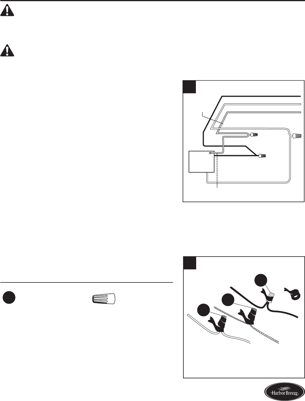
1. Connect with supply and fan wires according to the
diagram and these steps:
! Connect the Green/Ground wire from the downrod
and the Green/Ground wire from the mounting bracket
(D) to the Bare/Ground supply wire.
! Connect the Red wire from the receiver (R) to the
supply Black wire.
! Connect the Black wire from the receiver (R) to the
Black wire from the fan.
! Connect the White wire from the receiver (R) to the
supply White wire.
! Connect the White wire from the receiver (R) to the
White wire from the fan.
! Connect the Blue wire from the receiver (R) to the
Blue wire from the fan.
! Secure all wiring connections together with wire
connectors (BB).
Note:R The Black wire is hot power for the fan. The
Blue wire is hot power for the light kit. The White
wire is common for the fan and light kit. The Green
wire is the grounded wire. If house wires are different
colors than referred to above, it is recommended a
professional electrician determines the proper wiring.
Hardware Used
DD Wire Connector x 4
BLACK
WHITE
GROUND/GREEN (BARE)
WHITE
GROUND/GREEN
BLACK
FAN
WHITE
120 V Power
FROM
CEILING
FROM FAN
1
2. Wrap electrical tape (not included) around each
individual wire connector (DD) down to the wire.
DD
DD
DD
2
3
Lowes.com/harborbreeze
WIRING
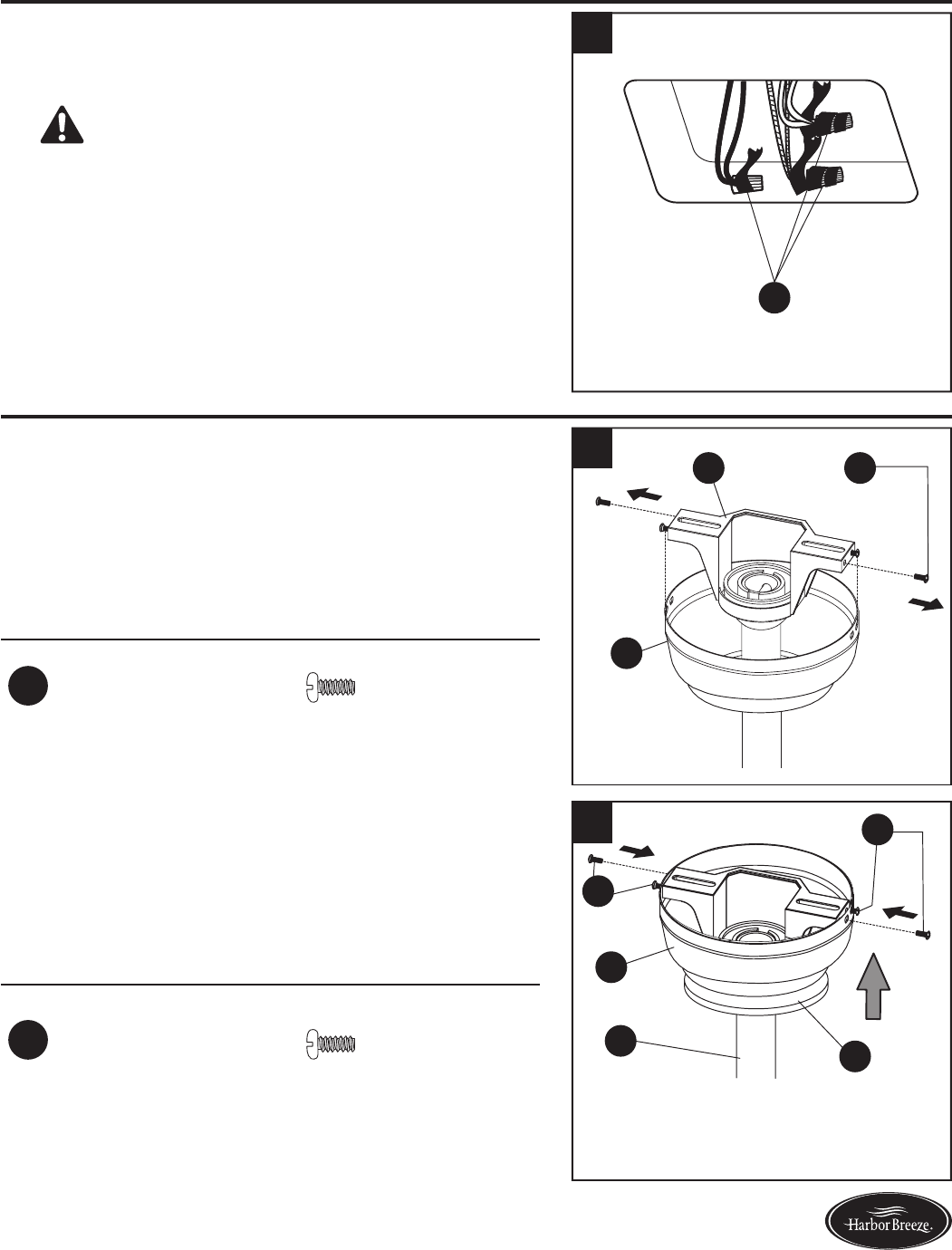
3. Turn the spliced/taped wires upward and gently push
the wires and wire connectors (DD) into the outlet
box.
WARNING: Ensure that no bare wire or wire
strands are visible after making connections. Place
the Green and White wire connections on opposite
sides of the outlet box from the Black and Blue (if
applicable) wire connections.
DD
3
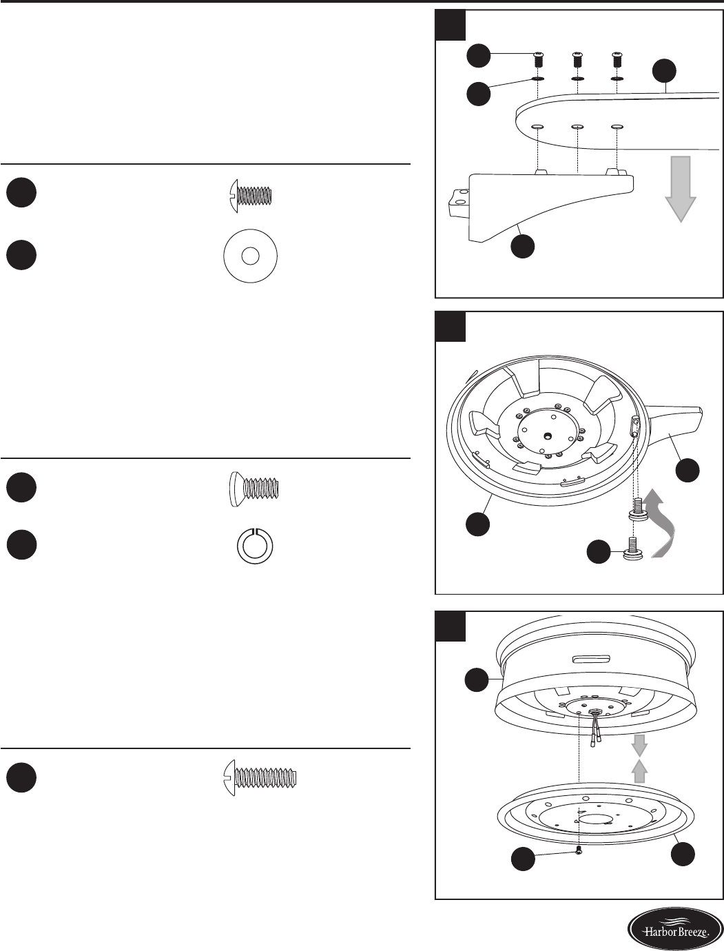
FINAL INSTALLATION
1. Remove the two mounting bracket screws (HH) from
the mounting bracket (C) and loosen the other two
screws about 1/4 in. Then align the canopy (B) up to
the ceiling over the loose mounting bracket screws
(HH). Place the keyholes of the canopy (B) into the
mounting bracket screws (HH) and rotate clockwise.
Hardware Used
HH Mounting Bracket
Screw x 4
B
C HH
1
2. Secure the canopy (B) with the previously removed
mounting bracket screws (HH) and securely tighten
all four mounting bracket screws (HH). Push the
canopy cover (K) up into the bottom of the canopy
(B) until it is locked.
Hardware Used
HH Mounting Bracket
Screw x 4
B
HH
K
A
2
HH
Note:
Closemount installation will not have the
downrod (A) and canopy cover (K).
4
Lowes.com/harborbreeze
FINAL INSTALLATION
3. Partially insert three blade screws (BB), along with
three blade washers (CC) through one blade (H)
and into one blade arm (G). Tighten each blade
screw (BB) with a Phillips screwdriver (not included),
starting with the one in the middle. Repeat this step
for the remaining blades (H) and blade arms (G).
Hardware Used
BB Blade Screw x 15
CC Blade Washer x 15
BB
H
G
CC
H
3
4. Align the holes of one blade arm (G) with two holes
on the motor assembly (E) and attach with two motor
screws (AA) and washers (LL) previously removed
(Step 5, page 8) with a Phillips screwdriver. Repeat
this step for the remaining blade arms (G).
Hardware Used
AA Motor Screw x 10
Motor Washer x 10
GG
E
AA
4
5. S$F+Q$!+.$!+B!&C$!B+>'!?&&$'!M#)&$!@%'$L@!T22U!#+%)&$,!
on the underside of the motor assembly (E) and
loosen the other three screws. Align the screw holes
+B!&C$!#(KC&!I(&!M#)&$!TVU!L(&C!&C$!#++@$.$,!?&&$'!M#)&$!
@%'$L@!T22U;!HC$.!'$M#)%$-!).,!&(KC&$.!)##!?&&$'!M#)&$!
screws (II).
Hardware Used
II Fitter Plate
Screw x 4
L
II
E
5
LL
5
Lowes.com/harborbreeze
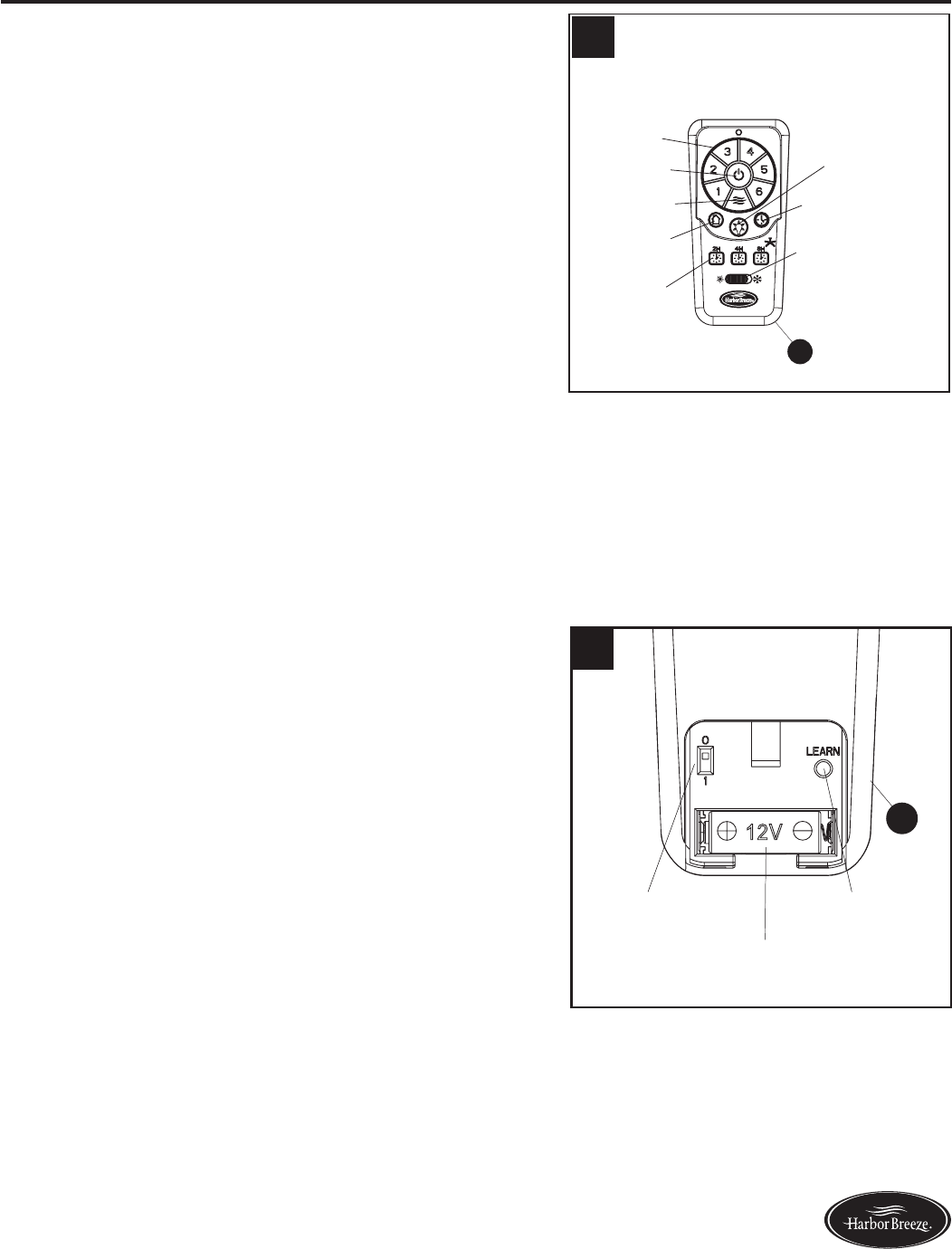
OPERATING INSTRUCTIONS
1A. To operate the fan using remote control (M), press
and release the following buttons:
Speed Control - Select fan speed 1 (low) - 6 (high).
Fan On/Off - Turns fan off or turns fan on at most
recently selected speed. Press and hold to turn off or
on the sounds from the remote control.
Natural Breeze - Simulates a natural breeze, as if
you were outside. Press any speed control button to
exit this mode.
Home Shield - When button is pressed, light blinks
&L(%$!&+!%+.?'F!<+F$!1C($#,!F+,$;!
Sleep Timer - Turns fan off after (2H) 2 hours, (4H) 4
hours or (8H) 8 hours.
Light Control - Turns light off or on.
Walk Away Light Delay - Delays turning off light for
1 minute which allows safe exit from room.
Season Slide Switch - Changes direction of blade
rotation. For warm weather slide switch to the left
and for cool weather slide switch to the right.
IMPORTANT: The dimmer function does not work
with CFL bulbs.
1B. Remove battery door from back of the remote control
(M) to access the following:
DIP Switch - Changes signal frequency (see
troubleshooting for instructions).
Learn - Syncs remote control to receiver (see
troubleshooting for instructions).
Battery Compartment - When necessary, replace
the 12-volt battery (O) and replace the battery door.
Home Shield
Light On/Off
Walk Away Light Delay
Speed
Control (1-6)
Fan On/Off
Natural Breeze
Sleep Timer
Season Slide Switch
2
+
+
H
M
12V
1B
DIP Switch
Battery Compartment
Learn Button
M
1A
6