Chongqing Xiegu Technology X5105 HF+50MHz transceiver User Manual X5105 Instruction Manual
Chongqing Xiegu Technology Co.,Ltd. HF+50MHz transceiver X5105 Instruction Manual
Users Manual

XIEGU COMMUNICATION
X5105
HF+50MHz Portable HF Transceiver
Instruction Manual
Chongqing Xiegu Technology Co.,Ltd.
www.cqxiegu.com
2
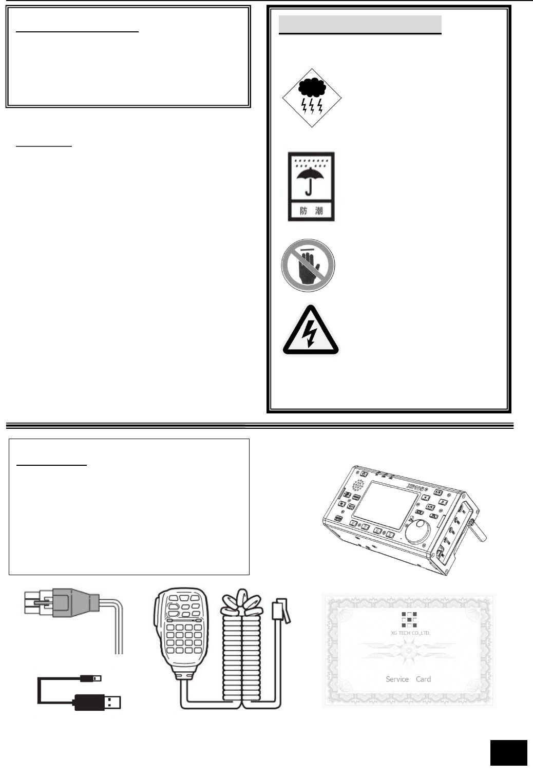
Important reminder:
Before operating the equipment, please
read our operating manual carefully and
keep the manual, so as not to lose.
Security considerations:
Do not use equipment during a lightning storm.
Damp-proof!
Don't illegal operations!
Note RF high-voltage of antenna connector!
Features:
l 3.6 inch LCD screen
l Built in 3800mAh large capacity battery
pack
l Built in ATU
l Covers all modes of HF, 50MHz band
(SSB/CW/AM/FM/RTTY/PSK)
l IF signal output
l Built in AF-DSP digital noise reduction
processor
l Equipped with trestle for desktop
operation
l Very small in size and ultra portable
Packing list:
Qty
① X5105...... ...... ...... ...... ...... ...... ...... 1
② Power supply cable........... ........... ......1
③ Hand microphone.............. ........... .....1
④ USB Cable........... ........... ........... .........1
⑤ Service card................. ........... ........... 1
①
②
④
③ ⑤

3
1 X5105 Specifications
Basic Specifications
Frequency range:
Receive: 1MHz-55MHz-
Transmitting: 160 meters -6 meters (Amateur band only)
Operating mode: A1A(CW),A3E(AM),J3E(USB/LSB),F3E(FM)
minimum frequency stepping: 1Hz
Antenna impedance: 50Ω
Operating temperature range: -10℃ ~ +60℃
Frequency stability: after turn on the radio 1-60 minutes is ± 2ppm,
@25℃:1ppm/hour
supply voltage: normal: 13.8VDC + 15%, negative grounding
Operating voltage: 9.0-15.0VDC, negative grounding
Current consumption: receive: 660mA@ Max transmit: 2.5A@ Max
Battery capacity: 3800mAh @12V
Dimensions: 160*100*46mm[does not include protrusion]
Weight: 0.94Kg[host only]
Transmitter parameters
Transmitter power:5W(SSB/CW/FM),1.5W(AM carrier), @13.8VDC
Modulation mode: SSB balanced modulation/AM low level amplitude modulation/FM
Variable reactance frequency modulation
FM Maximum frequency swing: ±5kHz
spur reduction: -45dB
Carrier suppression: >40dB
Sideband spurious: >50dB
SSB frequency response: 400Hz-2800Hz(-6dB)
Microphone impedance: 200-10k(conventional 600Ω)

4
Receiving parameters
Circuit type: double frequency conversion superheterodyne + audio DSP
IF frequency: first IF: 70.455MHz second IF: 10.695MHz third IF: 455kHz(FM)
Sensitivity
(PRE=on,ATT=off,NB=off,NR=off,SSB/CW/AM = 10dB S/N,FM = 12dB SINAD)
Image rejection: 70dB
If Rejection: 60dB
Selectivity: SSB:-6dB:2.4kHz/-60dB:4.6kHz
CW:-6dB:500Hz/-60dB:2000Hz
AM:-6dB:6.0kHz/-60dB:25.0kHz
FM:-6dB:12.0kHz/-60dB:25.0kHz
Audio output: 0.6W (8Ω,≤10% THD)
Audio output impedance: 4 – 16Ω
SSB/CW AM FM
500kHz-1.8MHz / 10uV /
1.8MHz-28MHz 0.25uV 2uV /
28MHz-30MHz 0.25uV 2uV 0.35uV
50MHz-54MHz 0.25uV 2uV 0.35uV
5
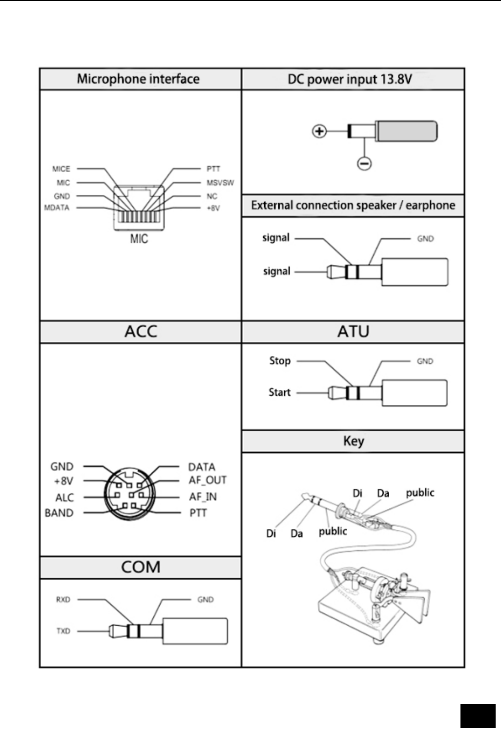
Interface definition

6
Charging and maintenance of internal battery
X5105 has a built-in 5000mAh battery pack. When the external power supply is not
connected, the battery pack supplies power to the X5105, when the X5105 is connected
with an external power supply, the circuit inside the machine automatically switches to
the external power supply.
Charging method:
1 In the menu, select [CHG] option, start charging function.
2 The external power supply voltage is set between 13.5V-14.0V and the power supply
is connected to the X5105 external power supply.
The host will automatically start charging.
3 Charging time is 10 hours. By then, the charge will automatically stop.
When the battery is powered for X5105, when the battery power is about to run out, the
power indication sign on the upper right corner of the screen is displayed as . At this
point, the X5105 should be charged or switched to an external power supply. During the
charging process, the casing of the machine has a slight fever.
Normally, the lifetime of the internal battery is about 4-5 years. Please replace the battery
when the battery has a noticeable capacity drop or charge fails.
When the X5105 is connected to an external power source, and when the X5105 is in the
transmitting state, it is strictly forbidden to disconnect the power supply so as not to
damage the power management chip.
Please turn off the power immediately when the machine shell is very hot near the
battery, and put the equipment in a safe and ventilated place. After confirming the
safety situation, please contact us for proper handling.
7
2 Description of equipment
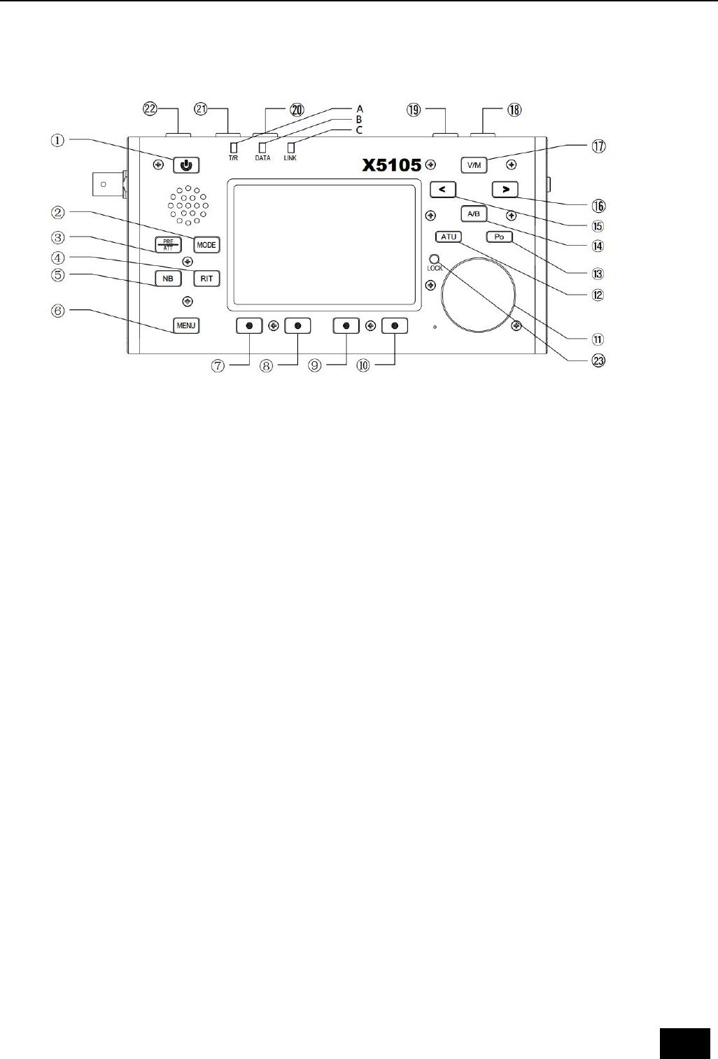
2.1 Front panel button function
① Power button
Press this button for a second to turn on or turn off the radio.
② Mode button
With this key, you can change the mode of operation and will cycle in the following mode:
[LSB-USB-CW-AM-FM]
③ PRE/ATT button
With this key, the preamplifier or pre attenuator will be turned on or be turn off in the
following states: [PRE=ON--ATT=ON--PRE/ATT=OFF]
④ RIT button
With this key, the receive frequency adjustment function is turned on or turn off.
⑤ NB button
With this key to turn on or turn off the NB function.
⑥ MENU button
With this key, you can switch the current display of the multi-function menu.
⑦ -⑩Multifunctional menu button
Press these four buttons to turn on or off the corresponding function displayed on the
menu area on the current screen.
○
11 Major tuning knob
The main tuning knob of X5105, can be used either for frequency regulation or for menus.
○
12 ATU button
When the key is pressed for a short time, the automatic antenna tuner will be connected
to the antenna port, by pressing this button for a long time, the automatic antenna tuner

8
will be started.
○
13 Po button
With this key, and with the main tuning knob, the power of the transmitter can be
adjusted. The range of adjustment is from 0.5W-5W, stepping for 0.5W.
○
14 A/B button
With this key, you will switch between VFOA-VFOB.
○
15 < button
With this key, the current frequency step carries one bit to the left.
○
16 > button
With this key, the current frequency step carries one bit to the right.
○
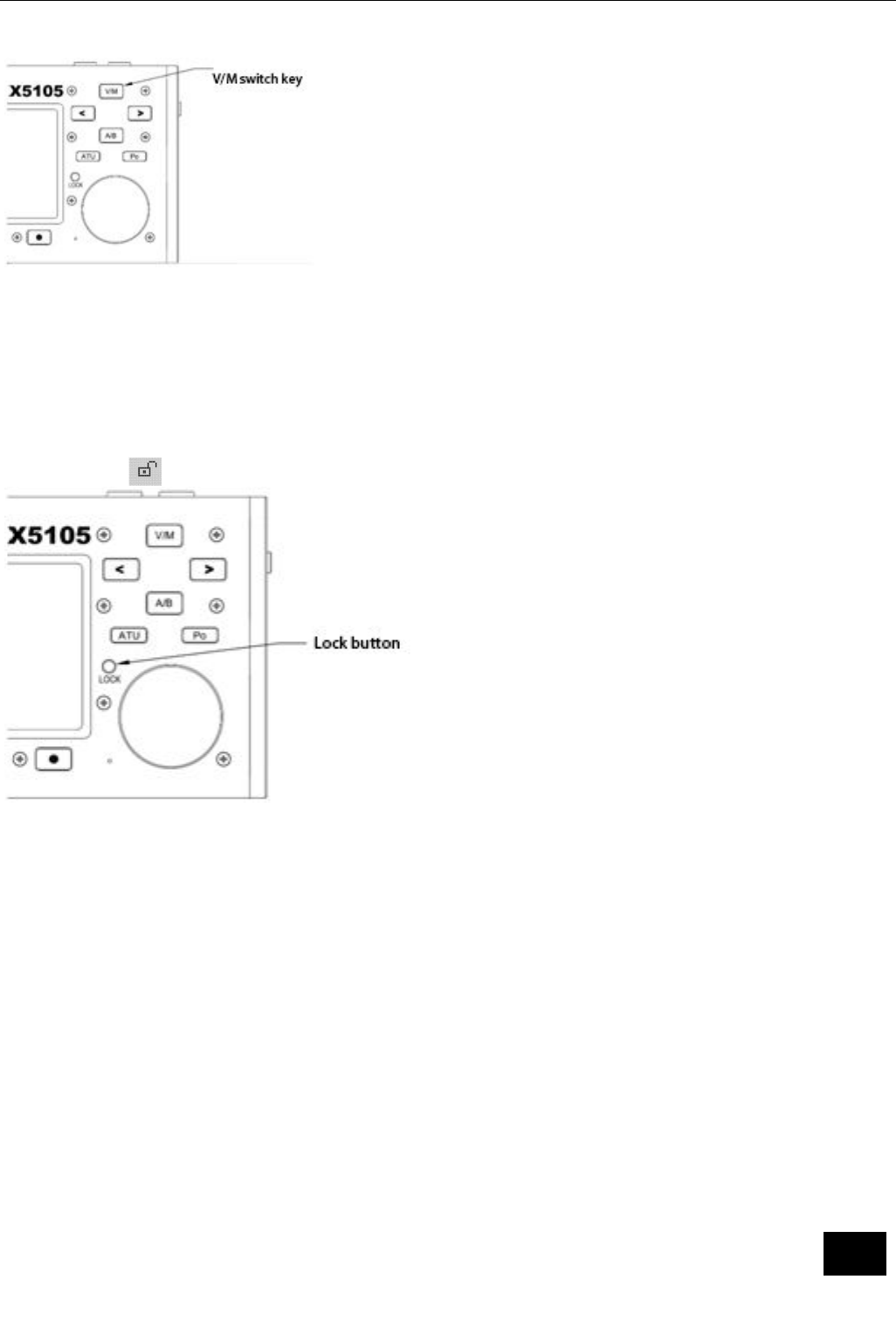
17 V/M button
With this key, you can switch between VFO mode and MEMO mode.
○
18 Up button
With this key, X5105 can be switched to higher frequency bands.
○
19 DN button
With this key, X5105 can be switched to lower frequency bands.
○
20 -button
With this key, you can reduce current volume.
○
21 +button
With this key, you can increase current volume.
○
22 PTT button
Press and hold this button, X5105 will go into the transmit state.
○
23 LOCK button
If you press this button for a short time, you will lock all buttons and knobs on the panel;
By pressing this button for a long time, you can set the backlight on / off.
Status indicator
A [T/R] B [DATA] C [LINK]
Transmit/Receive
switch indication
Data
indication
Peripheral
connection
indication
Indicator color description:
A T/R indicator
When the X5105 is in receiving mode, the indicator light is green.
When the X5105 is in transmitting mode, the indicator light is red.

9
B DATA indicator
When the data signal or channel are busy, the indicator light flashes.
C LINK indicator
When the host is connected with the external equipment, the indicator light will shine.
Function menu corresponding to 4 multi-function buttons below screen.
1.
A=B SPL NR NTH
Copy VFOA to VFOB Split On/Off Digital noise
reduction
Notch
2.
AGC FIL
Automatic gain
control on / off,
control speed
Filter selection
3.
M>V MW MC TAG
Save the current
channel in VFO and
return to VFO mode
Store current
channel
Clear current
channel
Channel display
frequency / custom
characters(Press this
button for a long
time to enter the
TAG edit mode)
4.
KEY KSP
Key manual /
automatic mode
selection
Automatic key rate
selection
10
5.
RE1 RE2 RE3 /
Set CW message
1(Press this button
for a long time to
enter the CW
message content
editor)
Set CW message
2(Press this button
for a long time to
enter the CW
message content
editor)
Set CW message
3(Press this button
for a long time to
enter the CW
message content
editor)
/
6.
SQL CMP MTR MSL
Squelch function Speech compression switch display
Po/SWR
Internal / external
microphone
selection
7.
SRM
Scan receive
mode(frequency
spectrum)
8.
IFO VER
IF output switch Version information
display
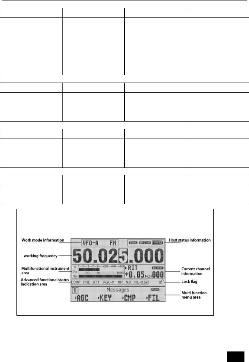
Screen display information
11
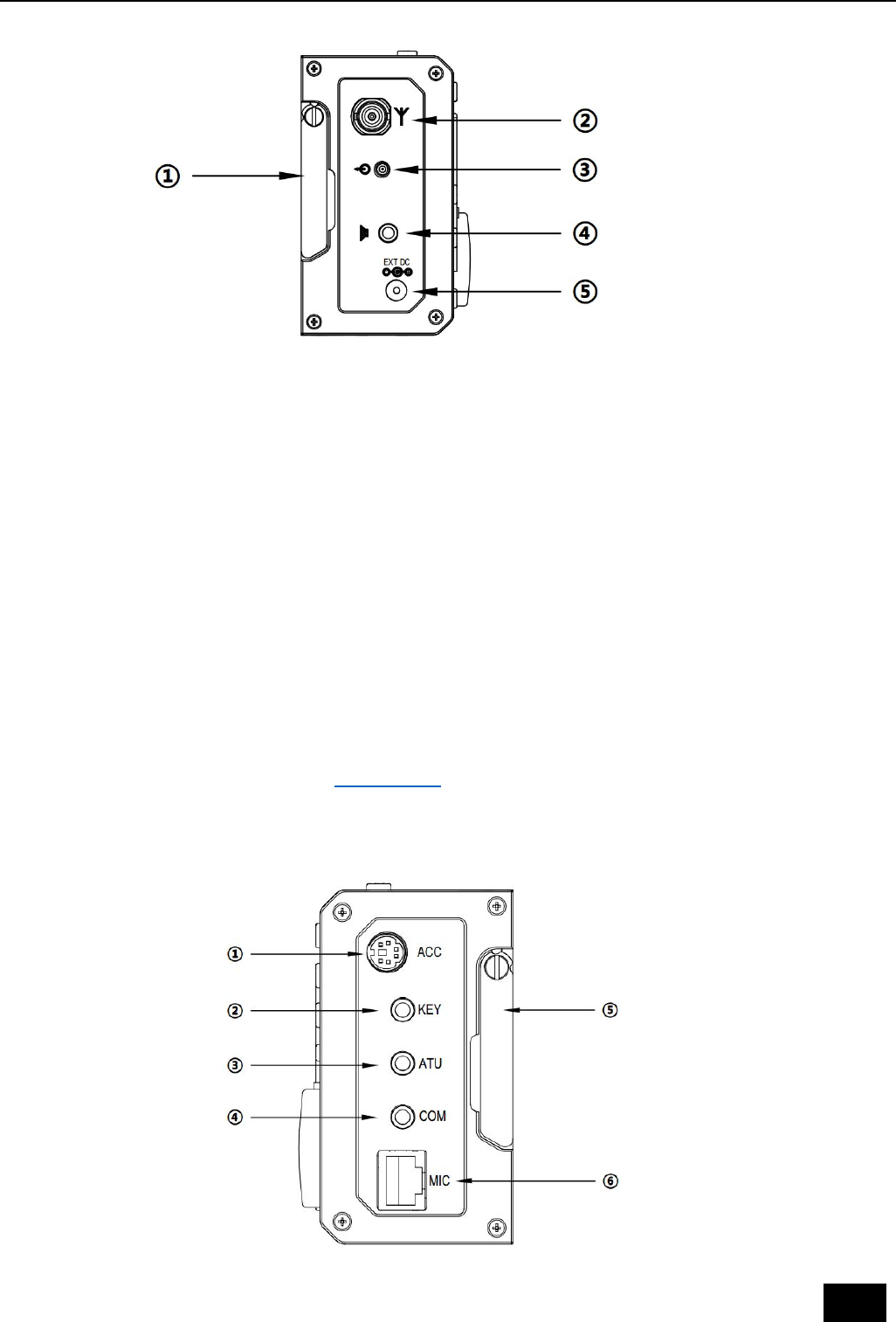
2.2 Left panel interface function
① Left bracket
Rotate the bracket when using it, when after using it, take it back to the side shield.
② Antenna interface
Connect the antenna to the 50 ohm coaxial cable with the Q9 connector.
③ IF signal output port
The first IF signal is output for use by the XDT1.
* XDT1 is a data terminal equipment of Xiegu.
④ External speaker / earphone interface
This interface is 3.5mm stereo socket (3 line, left and right channel machine linked
together), it can connect external speaker (impedance 4-16) or earphone.
⑤ DC power interface
The external DC power input interface, it uses the standard power cord to connect the
external stable DC power to this interface. The external DC power supply must be able to
provide the power output of the 13.8V@3A. The interface can also be used to charge for
internal battery.
2.3 Right panel interface function
12
① ACC interface
The interface is a 8PIN micro DIN interface, it can be used for external power amplifier,
ALC control, PTT control, band signal transmission, it can also be used to communicate
with the computer for PSK communication when the audio signal input / output.
② KEY interface
The interface is 3.5mm's stereo interface, which can be used to connect manual /
automatic telegraph keys.
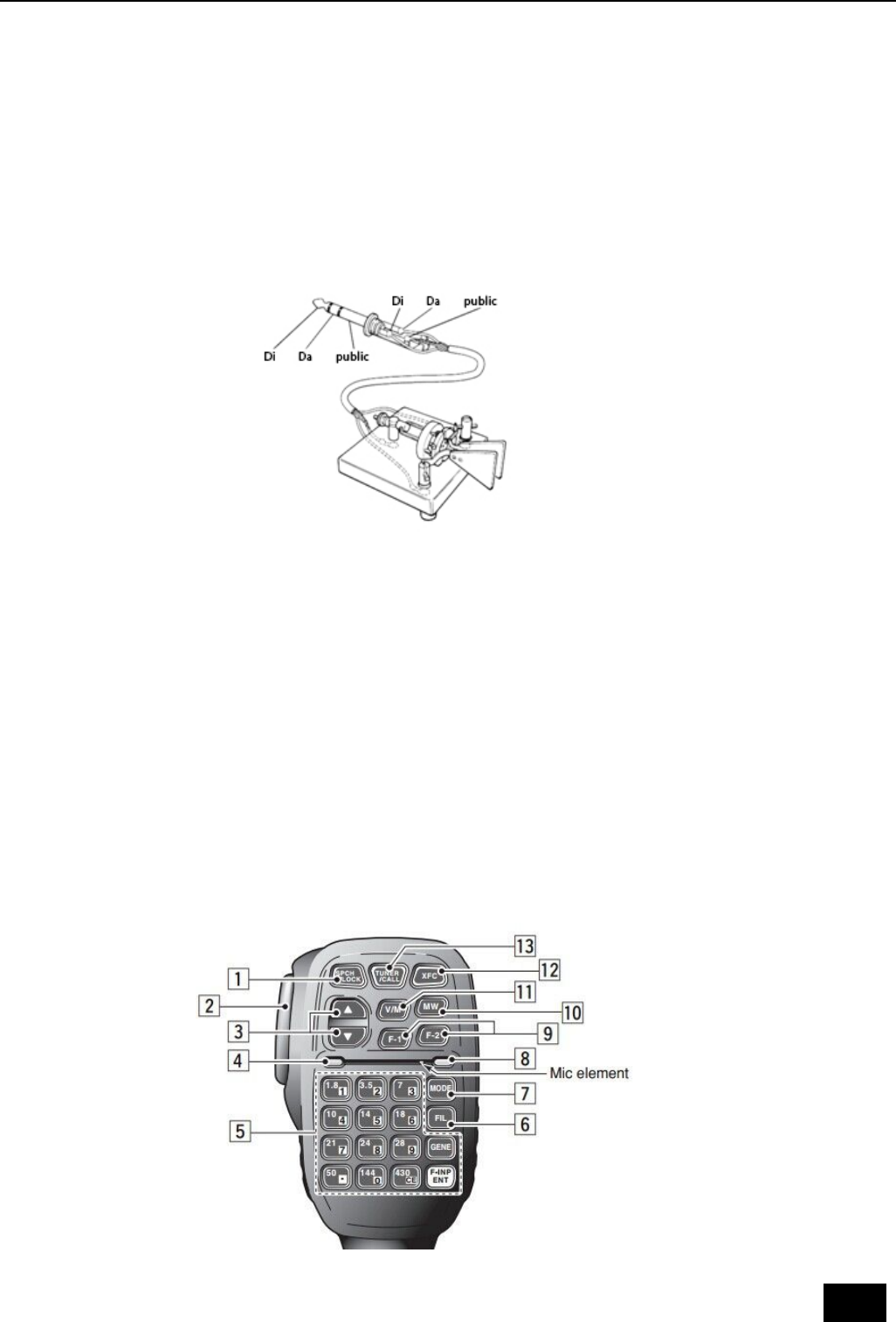
Key connection is shown in this figure:
③ ATU interface
The interface is a 3.5mm interface (3 lines) that can be used to control external power
amplifiers with antenna tuning.
④ COM interface
The interface is a 3.5mm interface (3 wire) which used for the connection of the
computer aided control system.
⑤ Right bracket
Rotate the bracket when using it, when after using it, take it back to the side shield.
⑥ MIC (microphone) interface
The interface can be used for microphone connections.
2.4 Handheld microphone function
13
1. LOCK button, you can lock the host button and the mouse button via this button, and
press it again to unlock.
2. PTT button, transmitting control button.
3. Move up/down, adjustable frequency increase, subtraction, or selection of items in
the menu.
4. Receiving / Transmitting indicator light, microphone operated indicator light.
5. Digital key
6. FIL button, built in filter selection.
7. MODE button, selection of host operating mode.
8. Function indicator lamp, No indication.
9. Function button, F1/F2 custom settings button.
10. MW button, store operation.
11. V/M button, frequency / channel switching.
12. XFC button, VFO-A / VFO-B switching.
13. CALL button, press this button for a long time to start the automatic antenna tuning in
the host.
3 Operation
3.1 Turn on / off transceiver
1. Turn on the transceiver: just press for a long time
2. Turn off the transceiver: in the boot state, press the key for a long time.
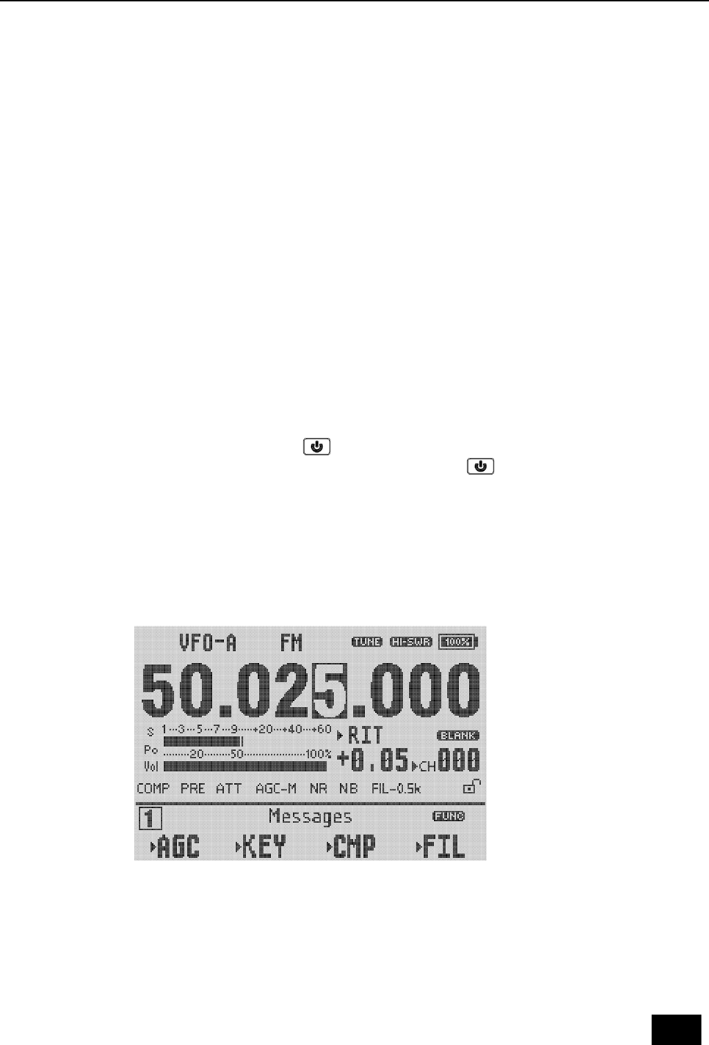
3.2 Battery / voltage display
1. When the battery is powered by the built-in battery, the remaining battery power of
the current battery will be displayed in the upper right corner of the display.
2. When using an external power supply, after switching the [VLT] menu, this position will
display the voltage value of the current external DC power source that is currently
connected to the transceiver.
3.3 Operating frequency band selection
The frequency range of X5105 covers 0.5~54MHz. The amateur frequencies in this range
are divided into multiple frequency bands and can be switched in a number of different
ways. You can complete the equipment operation according to the operation instructions
in this section.
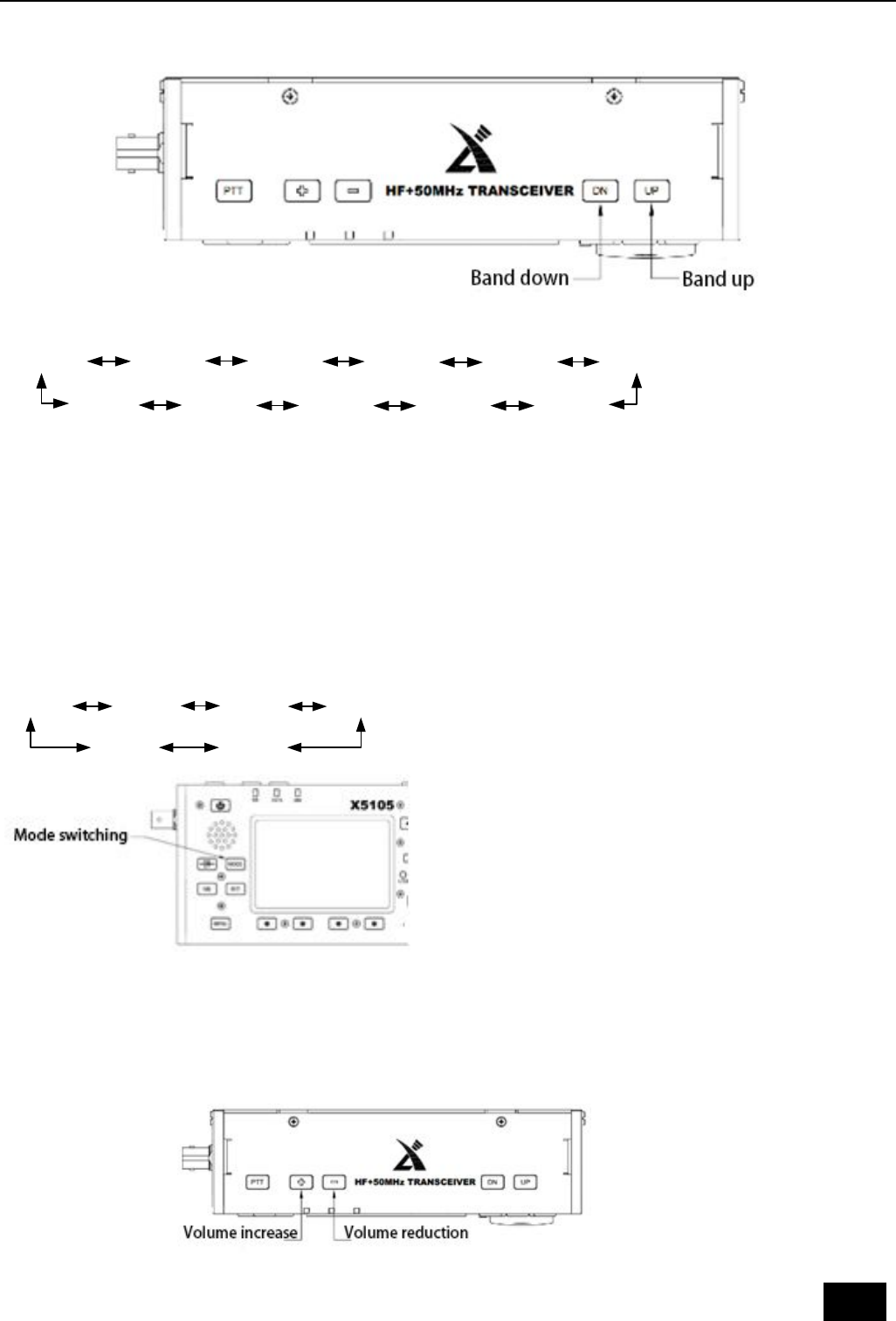
14
Operation method: press DN or UP key to switch to the next or last operation band
respectively.
3.5MHz 7.0MHz 10MHz 14MHz
18MHz
21MHz
24MHz
1.8MHz
28MHz
5.2MHz
50MHz
A. The opening of the 5MHz frequency band is based on the regulations of the country
(or region) where it is located.
B. Different versions of the machine have different frequency divisions, depending on
their country (or region) regulations.
C. VFO-A and VFO-B are two separate VFO modes, which can be set to different
frequency bands. Please refer to the [VFO settings].
3.4 Work mode selection
Press the [MODE] button to switch between all modes in a fixed order.
USB CWR
LSB
AM
CW
FM
*VFO-A and VFO-B can be set to different operating modes in the same frequency band,
thus realizing the different operation modes of "voice /CW".
3.5 Adjust the volume
Adjust the output volume according to the volume plus and minus buttons.
15
When using the AF-OUT port of the ACC interface, adjusting the volume level will do the
same for this port.
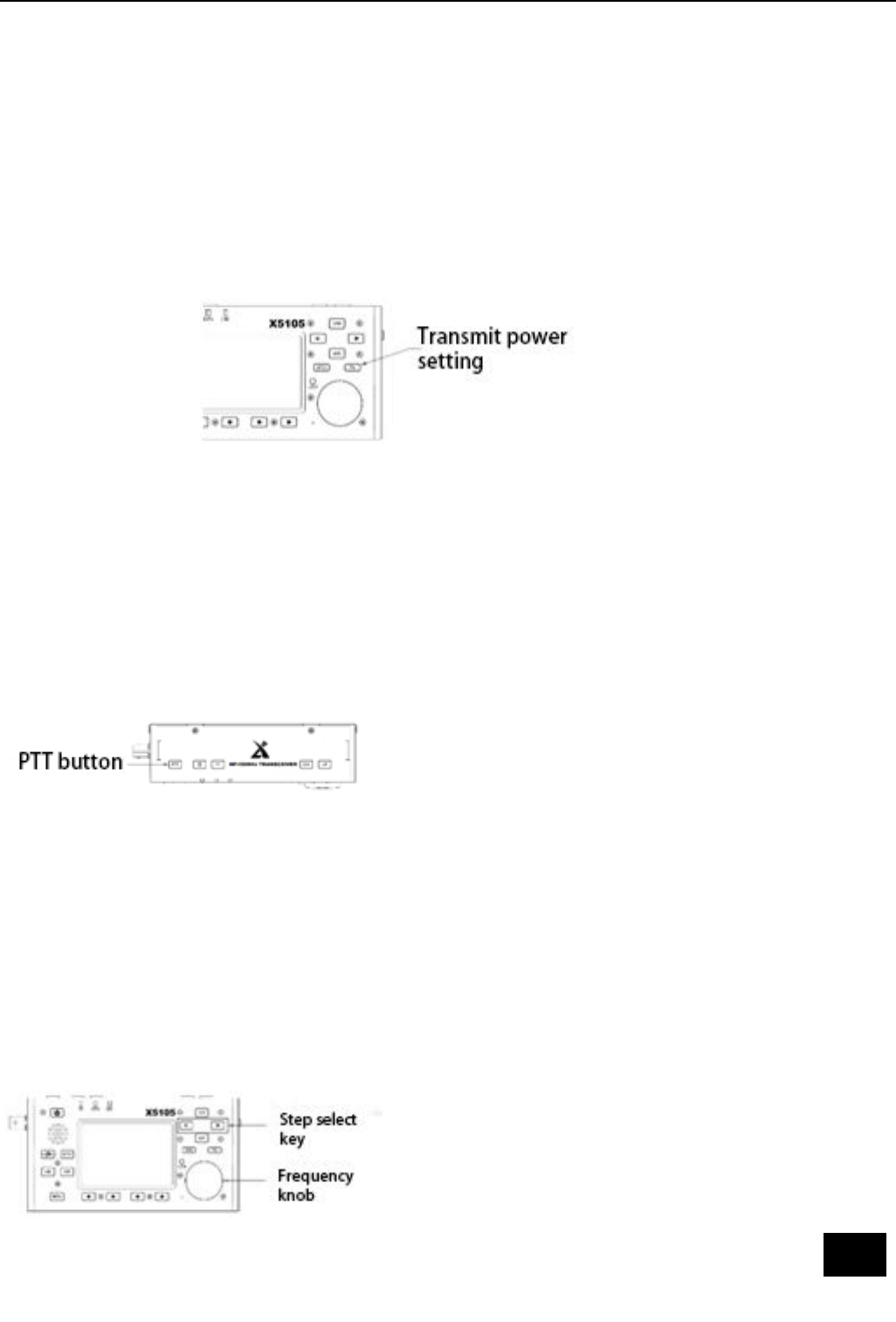
3.6 Regulated transmit power
Press the [Po] transmit power setting button, you can set the transmit power.
A. Press the [Po] button to enter the power setting state, and the screen will display the
Po power set bar table.
B. Rotate the big knob, set the power, step 0.5W.
C. When the settings are complete, press the [Po] button again, save and exit the setup
mode.
When you do not understand the current state of the antenna, minimize the set transmit
power value for the first time you use the X5105 transceiver.
3.7 Use the host PTT button
X5105 comes with a PTT button, you can start the transceiver's transmission through this
button.
Operation method:
A. Press this button to start the transmitting function.
B. Speaking into the built-in MIC hole, can be completed communications.
3.8 Set operating frequency
There are two ways to set the X5105 operating frequency, use the big knob to set the
frequency, or use the multi-function mic to set the frequency.
Operation method:
A. Use large knob to set frequency
Press the button [<] or [>], move the cursor of the frequency bit to the left or to the
right, select the frequency of the desired step.
Rotating frequency knob sets the frequency of the current step.
16
B. Use a multi-function microphone for frequency setting
Press the [F-INP ENT] button on the cursor, and the X5105 enters the frequency setting.
The cursor appears on the left of the frequency display bit.
Enter the desired frequency value in turn, and then press [F-INP ENT] button again to
complete the frequency setting.
For example, set the current frequency to 51.050000MHz, and press the order as
follows:
First, press the [F-INP ENT] button.
Please press the 51.050000 numeric key in turn.
Once again press the [F-INP ENT] button to complete the settings.
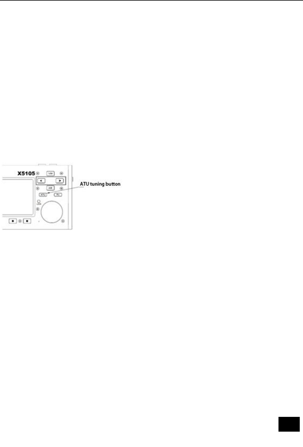
3.9 Start the ATU (automatic antenna tuner) into the tuning function
X5105 transceiver built-in an efficient automatic antenna tuner, which can help you easily
complete the erection and debugging of the antenna.
Press the [ATU] button for a long time, it will start the ATU auto tuning function. When
the tuning is complete, the host will automatically return to the receiving state.
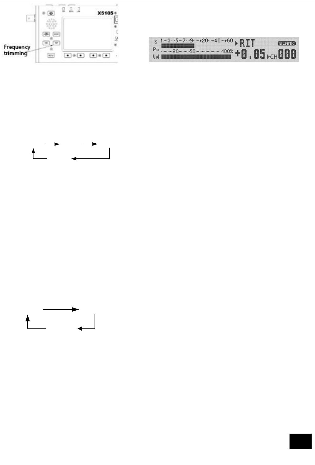
3.10 RIT (receive frequency trimming)
Relative to the set frequency, the RIT function can set the offset value of the actual
receiving frequency of the maximum ±5kHz.
Operation method:
A. Press [RIT] button to start RIT function.
B. The rotating knob can change the receiver frequency in the range of ±5kHz. The
screen has the corresponding area to display the frequency change value.
C. If you want to turn off the RIT function, press the [RIT] button again. When the RIT
function is enabled again, the last RIT setting will still be used.
D. If you want to clear the RIT offset, in the RIT open state, turn the knob and set the
offset to zero.
If the frequency offset range more you want, you can use pilot frequency transceiver
mode. Please refer to the VFO instructions for details.
17
3.11 Automatic gain control (AGC)
By adjusting the proper recovery time parameters of the AGC automatic gain control
system, the receiver can achieve the optimum state effect.
Operation method:
A. Switch to the second page menu, press the corresponding multi-function button to
select the AGC function.
B. The AGC function will be selected in the following order:
When you select "AGC-AUTO", the CW mode is actually "AGC-FAST", in voice mode is
"AGC-SLOW."
If AGC-OFF is selected, the AGC system is turned off and the display of the S table is
stopped.
3.12 Preamplifier / preamplifier (PRE/ATT)
Pre amplifier (PRE) and pre attenuator (ATT) can improve the receiver's listening effect.
When the signal is weak, the preamplifier can be switched on to increase the signal
strength. When the signal is strong, the preamplifier can be switched on to reduce the
signal strength.
Of course, you can also choose to turn off the circuit unit so that the signal will by pass.
Operation method:
A. Press the [PRE/ATT] button to start the function.
B. The switching sequence will follow the following loop:
In the low frequency waves (less than 10MHz) operation, the preamplifier can be closed,
then let signal in by-pass state, it will be more conducive to improve the receiving effect,
And it can avoid the blocking of receiver caused by strong interference signal. Typically,
when the S table is still changing, the preamplifier is not need to turned on.
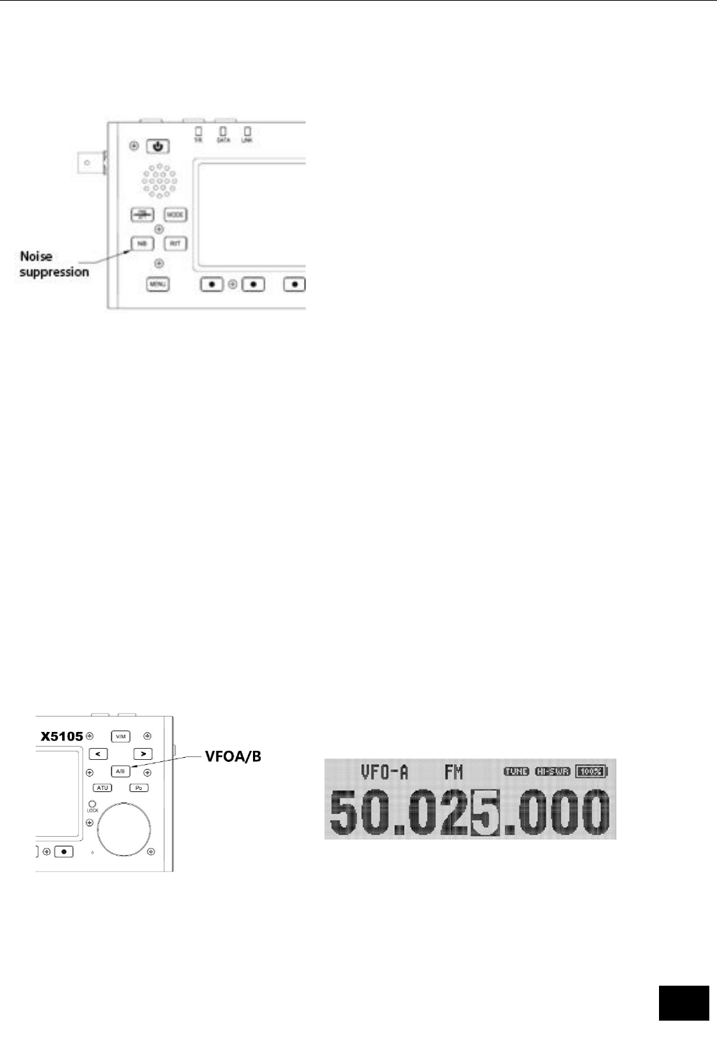
3.13 Noise suppressor NB
Noise suppressor can effectively eliminate some specific pulse type interference,
especially the noise produced by the automobile ignition system, and can improve the
receiving effect obviously.
Operation method:
AGC-
FAST
AGC-
SLOW
AGC-
AUTO
AGC-
OFF
ATT
PRE
OFF
18
A. Press the [NB] button, the screen appears corresponding prompt information, NB
function is turned on.
B. Press the [NB] button again, it will turn off the NB noise suppressor.
* The NB function can only suppress the pulse noise of a specific type, and can not
replace the NR noise reduction function.
3.14 Pilot frequency operation SPL and VFOA/B setting
There are two independent VFO in X5105 transceiver, which can set different frequencies
and modes respectively. Set the VFO reasonably, and with the menu SPL function, you can
easily achieve pilot frequency transceiver operation mode.
VFO settings:
A. Press the [A/B] button, you can switch between VFO-A and VFO-B.
B. When you switch to a certain VFO state, you can set the current VFO's working
frequency, working mode, and so on.
Pilot frequency transceiver operation method:
A. First set the receiver frequency and mode (VFO-A).
B. And then set the transmit frequency and mode (VFO-B).
C. Press [MENU] button, switch to the first page menu, select the SPL function, it opens
the pilot frequency transceiver working mode.
*You can also make full use of VFOA/B to set different frequencies or modes, so double
frequency monitoring can be achieved via real-time switching.
3.16 VFO mode /MEMO mode (V/M) setting
Transceiver can switch between VFO mode and MEMO mode, and realize flexible
operation mode.
Operation method:
A. Press the [V/M] button, you can switch between the VFO mode and the MEMO mode.
19
B. In the current mode, press the [V/M] button, and then switch to another mode.
3.17 Lock button operation
The lock key (LOCK) can avoid the incorrect triggering of the transceiver and the
microphone during outdoor operation.
Operation method:
A. Press the [Lock] button for a long time to start the lock.
B. Press the [Lock] button for a long time again to turn off the lock.
C. The icon appears on the corresponding area of the screen.
3.18 CW communication
Operate with a hand key or an external keying device.
Operation method:
A. Insert the plug of the key (three wire) into the KEY interface on the right.
B. Press the [MODE] button and switch mode to CW (or CWR).
C. Press the [MENU] button for a long time, adjust the Menu #08 (CW DELAY) and set the
delay time (default: 500ms). Press the [SAVE] button to save the new settings and exit
the menu mode.
D. Press the CW key, you can doing the CW communication.
E. The tone of the CW sidetone can be adjusted by Menu #09 (CW TONE), as follows:
① Press [MENU] button for a long time to enter menu mode.
② Regulating Menu, #13 (CW, TONE).
③ Select the required tone, range from 200~2000Hz to adjustable, and the default

20
value is 800Hz.
④ After you complete the operation, press the [SAVE] button briefly, save the new
settings and exit the menu mode.
Using the built-in automatic key controller makes it easy to generate CW points, with
the following methods of operation:
① Press the [MENU] button briefly, switch to the fourth page menu, and select the
KEY function as KEY-A.
② Select the KSP function, rotate the frequency knob, adjust the automatic key rate,
press the corresponding function button of KSP again, save and return.
3.19 Channel storage
Regular channel storage:
A. In VFO mode, parameters such as frequency, mode and advanced functional status are
adjusted.
B. Press the [MENU] button briefly, switch to the third page menu, select the V>M
function, and start the channel editor.
C. If the current channel is empty (not storing channel information), the channel number
will flicker. Press the MW function key for a long time, after a "di" sound, the
frequency information has been successfully stored on the channel.
D. If the current channel has stored information, the channel number will not flicker.
Rotate the knob to the nearest empty channel, press the MW function key for a long
time, after a "di" sound, indicates that frequency information has been successfully
stored on the channel.
Adjust storage channel:
A. If in VFO mode, press the [V/M] button on the panel, it will enter the channel mode.
B. Turn the knob, you can switch the current channel, the channel number will change
accordingly.
Clear channel storage:
A. In the channel mode, press the [MENU] button, switch to the third page menu, press
the MC function key, start clear channel editing.
B. At this point, the channel name or frequency value starts flashing. Press the MC
button for a second, it will be heard twice "Di" sound, this indicates that the data in
the current channel store is cleared and the channel number starts flashing, this
indicating that the current channel number is empty.
3.20 Channel naming
The stored channels can be named with the labels of letters and numbers to facilitate
channel classification (e.g., work). You can do the editing in the menu mode as follows:
A. Bring up the channel you want to name.
B. Press the [MENU] button for a long time, enter the menu mode, rotate the knob,
transfer Menu#23 (MEMTAG).
C. Press the button [>] to start the tag edit.
D. Rotate the knob, select the first letter (or number, symbol) you want to edit, and then
press [>] to enter the next letter position.

21
E. Turn the knob again, select letters, numbers, characters, and press [>] to enter the
next letter position.
F. Repeat fifth steps until the tag editing is complete. Press the [MENU] key for a second,
save the contents of the set tag and return to the normal operating state. In channel
mode, press the [MENU] button briefly, switch to the third page menu, press the TAG
function key, and display the label named for this channel.
*You can press the TAG function key for a second, and you will transfer Menu #23(MEM
TAG).
3.21 The menu system can personalize the transceiver and make it more in line
with your habits.
Operation method:
A. Press the [MENU] button for a second and enter the menu mode.
B. Press the [ V/A ] and [ A/B ] buttons to set the parameters you want.
C. Rotate the knob to bring up the menu item you want to set.
D. After the setting is complete, press the [MENU] key for a second, save the current
setting and exit the menu mode.
* In the above fourth steps, if you press the [QUIT] button briefly, you will not save the
new settings and exit the menu mode.
Menu system description
Menu item function Set value default
01 Filter 1 Fc Filter 1 center frequency point (CW filter) 1M~100M 10.695M
02 Filter 2 Fc Filter 2 center frequency point (SSB filter)
1M~100M 10.695M
03 Filter 3 Fc Filter 3 center frequency point (AM filter) 1M~100M 10.7M
04 Filter 1 Bw Filter 1 bandwidth (CW filter) 100Hz~100kHz
500
05 Filter 2 Bw Filter 2 bandwidth (SSB filter) 100Hz~100kHz
2400
06 Filter 3 Bw Filter 3 bandwidth (AM filter) 100Hz~100kHz
6000
07 RF Gain Receive RF gain 10~100% 65%
08 CW Delay CW T/RX switch delay 0~10000mS 500mS
09 CW Tone CW transmit side tone frequency 200Hz~2000Hz
800Hz
10 SSB Tx Lv SSB transmit modulation level 10~100% 50%
11 AM Tx Lv AM transmit modulation level 10~100% 50%
12 NFM Tx Lv NFM transmit modulation level 10~100% 100%
13 SSB Rx Lv SSB receive audio gain 10~100% 50%
14 AM Rx Lv AM receive audio gain 10~100% 50%
15 NFM Rx Lv NFM receive audio gain 10~100% 40%
16 BackLight Backlight brightness 0~100% 100%
17 Ref Clock Reference clock frequency 1M~100M 26M
18 OutBand EN
Out of band permit 0~1 0
19 NFM Tx IF NFM transmit if 1M~100M 10.697M

22
3.22 Restore factory settings:
When the parameter setting error and cannot be restored to the original parameters, you
can use a restore factory settings function reset operation of the transceiver and
transceiver on all the settings, the stored data will be cleared.
Operation method:
Press the RST button to restore the factory settings.
3.23 PSK communications and wiring instructions
X5105 transceiver can be connected with the computer, using the corresponding
computer PSK software to complete the PSK communication.
Operation method:
A. Connect the output of the SPK port to the AF IN of the PC using the stereo plug wire.
B. Use ACC plug (MINI-DIN8) to connect the computer audio output to X5105. The
computer end is a stereo plug.
C. The data line is used to connect the X5105 to the computer and to ensure that the
driver is properly installed. The HRD software can control the X5105 transceiver.
D. After entering the HRD software, and then enter the PSK work interface, at this time
you can communicate with PSK, X5105 transceiver is also controlled by the HRD
software.
E. Adjust the volume of the host to the right, observe the HRD software interface, avoid
the audio amplitude is too large, resulting in no communication.
* In order to prevent interference, the radio and computer must be grounded. Data lines
and audio cables, please install the EMC magnetic ring, and install as close as possible to
the host of the radio station.
3.24 Band data format
The ACC port of the X5105 provides band data for each band. The band data can be used
to control the peripheral, to make automatic band switching, or to identify the band
information for other devices.
Band Voltage
Band Voltage
Band Voltage
Band Voltage
1.8MHz
230mV 7MHz 920mV 18MHz 1610mV
28MHz 2300mV
3.5MHz
460mV 10MHz 1150mV
21MHz 1840mV
50MHz 2530mV
5.0MHz
690mV 14MHz 1380mV
24MHz 2070mV
/

23
After-sales service policy
1. Warranty:
This product has two years warranty effective from the date of purchase. This warranty
covers only manufacturing- and parts defects. It does not cover damage caused by
lightning, excess voltage on the power supply, accidental damage or purposeful damage
or misuse.
If the product needs warranty repair within two weeks of receiving the product, XieGu
will pay for the shipping both ways. After two weeks XieGu will pay only for return
shipping.
If the product is not covered under warranty, the customer pays for shipping both ways
plus the cost of the repair.
2. Warranty limitations:
Any of the following will void the warranty applicable to the product and its accessories:
A. Modification-, removal-, or maintenance of the internal circuitry, without permission
and authorization;
B. Unauthorized change of product’s embedded software;
C. Immersion in liquid or signs of external damage;
D. Warranty period expired;
E. Product’s serial number is missing, torn or blurred so we cannot determine if
the radio is under warranty;
F. Product was not bought from XieGu or authorized distributor of XieGu.
*None of the following conditions, are covered by the warranty:
A. Damage caused by improper use by the user;
B. Damage caused by an accident;
C. Damage due to incorrect testing, maintenance, debugging, or other changes;
D. Damage is not caused by the material or the quality of production;
E. Damage to the shell or other external components due to improper use.
Contact us: service@cqxiegu.com

NOTE
This equipment has been tested and found to comply with the limits for a Class B digital device, pursuant
to Part 15 of the FCC Rules. These limits are designed to provide reasonable protection against harmful
interference in a residential installation. This equipment generates, uses and can radiate radio frequency
energy and, if not installed and used in accordance with the instructions, may cause harmful interference
to radio communications.
However, there is no guarantee that interference will not occur in a particular installation. If this
equipment does cause harmful interference to radio or television reception, which can be determined by
turning the equipment off and on, the user is encouraged to try to correct the interference by one or more
of the following measures:
Increase the separation between the equipment and receiver.
Connect the equipment into an outlet on a circuit different from that to which the receiver is connected.
Consult the dealer or an experienced radio/TV technician for help.
1. Changes or modifications to this device not expressly approved by YAESU MUSEN could void the
user’s authorization to operate this device.
2. This device complies with part 15 of the FCC Rules. Operation is subject to the following two
conditions; (1) this device may not cause harmful interference, and (2) this device must accept any
interference including interference that may cause undesired operation.
3. The scanning receiver in this equipment is incapable of tuning, or readily being altered, by the User to
operate within the frequency bands allocated to the Domestic public Cellular Telecommunications
Service in Part 22.
FCCID:2ANLH‐X5105
24

25
Xiegu communication
www.cqxiegu.com