Chromalox Gnit 5 Users Manual PK479 3 CHX
GNIT-5 IM-PK479
GNIT-5 to the manual 65501f46-678e-4b41-819c-f795d77b99ed
2015-02-04
: Chromalox Chromalox-Gnit-5-Users-Manual-364644 chromalox-gnit-5-users-manual-364644 chromalox pdf
Open the PDF directly: View PDF ![]() .
.
Page Count: 2
Chromalox
®
DIVISION
4
SECTION
GNIT
SALES
REFERENCE
DATE
SERVICE REFERENCE
Installation Instructions
PK479-3
161-506172-001
AUGUST, 2006
(Supersedes PK479-2)
© 2010 Chromalox, Inc.
Model PCN Temperature Volts Max Capillary Stock
Range (˚F) Amps. Length (Ft.)
GNIT-5 360946 30 to 220 120/240 25 5 S
GNIT-12 360954 30 to 220 120/240 25 12 S
Specifications —
Other temperature ranges available. Contact your local Chromalox Sales office.
Features:
• Rugged Design
• Moisture and Corrosion Resistant
• Teflon®Covered Capillary/Bulb
• Large Setpoint Dial
• Easy Installation
• Line Voltage
• DPST 25 Amp Switch
GENERAL
FIRE/EXPLOSION HAZARD. This thermostat is not
intended for use in hazardous atmospheres where
flammable vapors, gases, liquids or other com-
bustible atmospheres are present as defined in
the National Electrical Code. Failure to comply can
result in personal injury or property damage.
NOTICE: Type GNIT Thermostats are designed for temperature
control service only. Because they are not fail safe, they should
not be used for temperature limiting duty.
The system designer is responsible for the safety
of this equipment and should install adequate
back-up controls and safety devices with their
electric heating equipment. Where the conse-
quences of failure could result in personal injury or
property damage, back-up controls are essential.
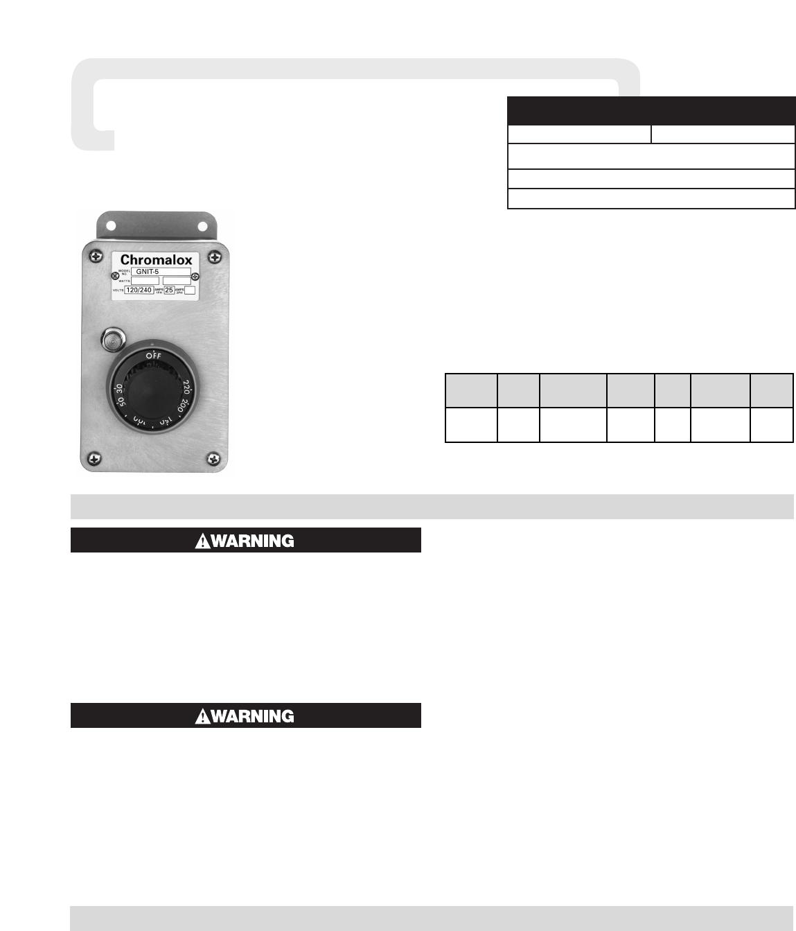
The GNIT Non-Indicating Corrosive Resistant Thermostat is
designed for applications in atmospheres where corrosive material is
present. The double pole/single throw thermostat is available with
either a 5 foot or 12 foot copper capillary which is sleeved with
Teflon®. The Teflon®also covers the bulb. The thermostat is
designed for 25 amperes resistive loads for either 120 or 240 Vac.
Specifications:
Range 30 to 220˚F
Switch Action DPST (Double Pole/Single Throw)
Current 25 Amperes, 120 or 240 Vac
Accuracy ±9˚F
Load Lamp 120 Vac or 240 Vac
Capillary Length GNIT-5, 5 Foot
GNIT-12, 12 Foot
Diameter of Teflon®Cover 5/16” OD
Application Notes
1. Customer external fuse required.
Process Temperature Differential — is variation in controlled
process temperature between maximum, when thermostat turns
OFF and minimum, when thermostat turns ON. This spread in
temperature may be minimized by:
1. Making sure control is mounted to vertical surface. (See Step 1,
MOUNTING.)
2. Avoid excess heating capacity (oversized heaters).
3. Locating control sensing bulb in optimum position between
heat source and work.
MOUNTING
Note: Do not mount thermostat where it will be subject to vibra-
tion or shock. Do not mount adjacent to a large magnetic contac-
tor, as vibration and shock will cause thermostat to interact errati-
cally — resulting in chattering of the contactor.
The air temperature in and around the thermostat enclosure
should be kept as near to normal room temperature as possible…
never above 150˚F or below 30˚F.
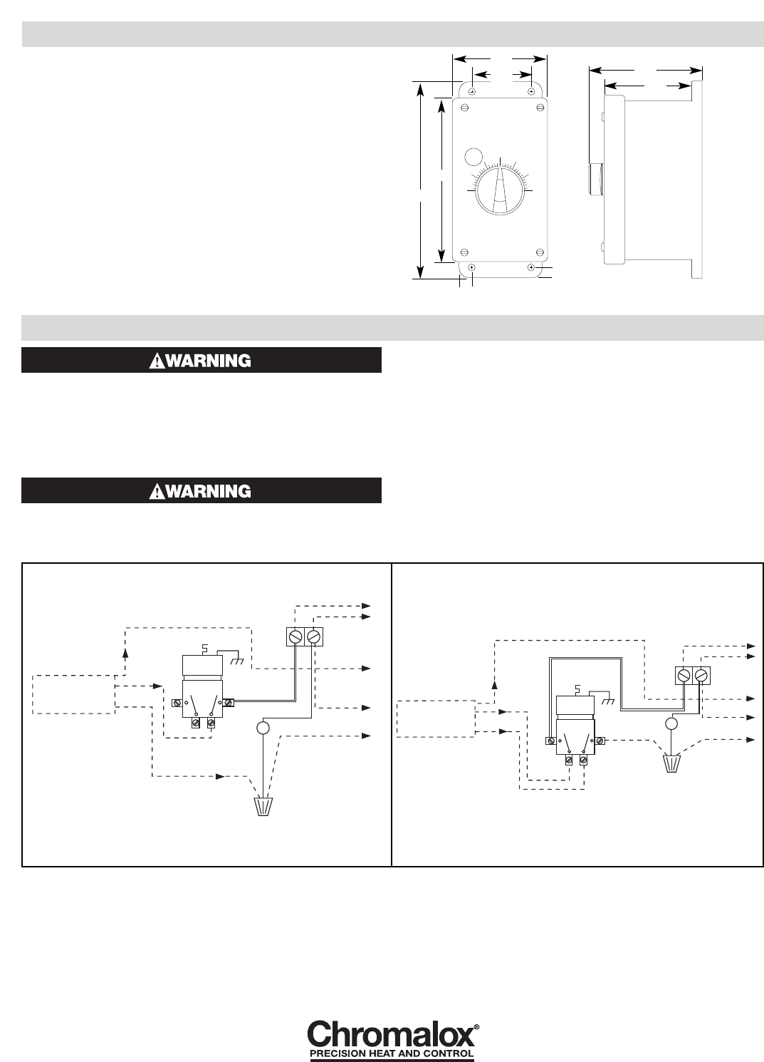
1. Thermostat must be mounted in a vertical position only.
2. Use sheet metal or wood screws through the four 1/4” diame-
ter mounting holes in baseplate to mount control.
GNIT Moisture and Corrosion
Resistant Industrial Thermostat
Teflon®is a registered trademark of DuPont Co.
WIRING
ELECTRIC SHOCK HAZARD. Disconnect all power
before installing or servicing thermostat. Failure
to do so could result in personal injury or property
damage. Thermostat must be installed by a quali-
fied person in accordance with the National
Electrical Code, NFPA 70.
ELECTRIC SHOCK HAZARD. Any installation
involving thermostats must be performed by a
qualified person and must be effectively grounded
in accordance with the National Electrical Code to
eliminate shock hazard.
1. Electric wiring to thermostat must be installed in accordance
with the National Electrical Code and with local codes by a quali-
fied person. CAUTION: Use copper conductors only.
2. Entrance for wiring is provided by two 1/2” conduit
holes on each side of the unit.
3. Remove four face mounting screws and pull off front cover.
4. Connect wires according to wiring diagrams (Figures 2 & 3).
5. Replace cover and tighten screws.
6. Note: If load amperage or voltage rating exceeds switch rat-
ing, a contactor must be used. Contactor and wiring to be sup-
plied by customer.
1347 HEIL QUAKER BLVD., LAVERGNE, TN 37086
Phone: (615) 793-3900 www.chromalox.com
MOUNTING
3. NOTICE:
A. Do not bend or deform sensing bulb. This will alter control
calibration.
B. Do not kink capillary tube. The resulting constrictions in
fluid flow can destroy control function or broaden tempera-
ture differential. Minimum capillary tube bending diameter
is 1/2” I.D.
C. Any deformations of bulb or capillary that result in leakage
of fluid from control renders control inoperative.
D. Avoid passing control capillary tube through zones which
have temperatures in excess of controlled process tempera-
ture. Erratic control or destruction of control function may
result.
P
NR25
10 AWG
Amber
Neutral
(White)
120V 25 Amps Max Line
Fused Disconnect
By Customer
Hot
(Black)
Ground
(Green)
Nut supplied to
ground control.
Wire Nut
Heater Load
(Black)
Ground
(Green)
CC
NO NO
Connect heater leads
to wire nut provided
and one side of the
terminal block.
Connect heater ground
to ground screw on NR25.
Connect hot line to
screw terminal provided and
neutral line (with pilot light &
heater lead) to wire nut provided.
Connect ground nut on NR25.
P
NR25
10 AWG
Amber
240V 25 Amps Max Line
Fused Disconnect
By Customer
Ground
(Green)
Nut supplied to
ground control.
Wire Nut
Heater Load
(Black)
Ground
(Green)
CC
NO NO
Connect wire to 0.250" screw-on
connector. Connect heater lead, pilot light
lead, and wire from control to wire nut
provided. Connect the other heater lead to
the terminal block. Connect heater ground
with grount nut on NR25.
Connect power to 0.250"
screw-on connectors
provided. Connect ground to
ground nut on NR25.
120 Volt 240 Volt
Note: Dotted lines represent wiring by
customer. 10 AWG wire recommended.
Note: Dotted lines represent wiring
by customer. 10 AWG MTW or
THHN wire recommended.
Figure 2 Figure 3
Figure 1
4.25
2.63
5.88
3.75
7.13
0.44
0.44
3.38
Side View
Front View
Note: Terminals provided for ther-
mal fuse or other remote shutdown
device. If no remote device, termi-
nals must be jumpered. Note: Terminals provided
for thermal fuse or other
remote shutdown device. If
no remote device, termi-
nals must be jumpered.
Limited Warranty:
Please refer to the Chromalox limited warranty applicable to this product at
http://www.chromalox.com/customer-service/policies/termsofsale.aspx.
