ChronoTrack Systems CON-M200-USA1 Mobile RFID 4 Port Data Collection Device User Manual 1
ChronoTrack Systems LLC Mobile RFID 4 Port Data Collection Device 1
Contents
- 1. Users Manual 1
- 2. Users Manual 2
- 3. Users Manual 3
Users Manual 2


•ChronoTrack Components
•ChronoTrack Setup
•ChronoTrack Read Zone & Handling Unwanted
Reads
•Available ChronoTrack Resources

•Approximate weight: 30/26 lbs for 800/400
•Supports up to 28 ft. timing lines per controller
•Multiple communication options: LAN, WiFi and
Cellular
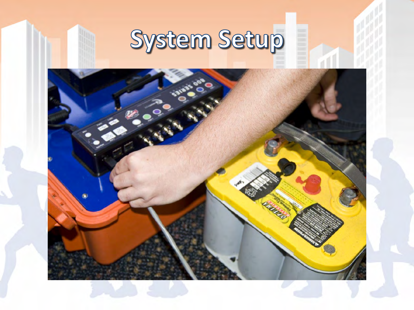
•Redundant Data Collection/Storage
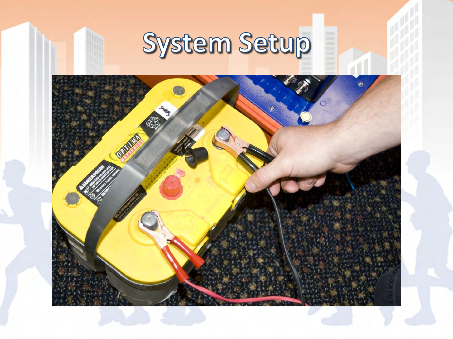
•Redundant Power: Operates on AC, Aux Power
and Internal Batteries with seamless transfer
•Touch Panel Interface
•Does not require tuning, highly resistant to
interference
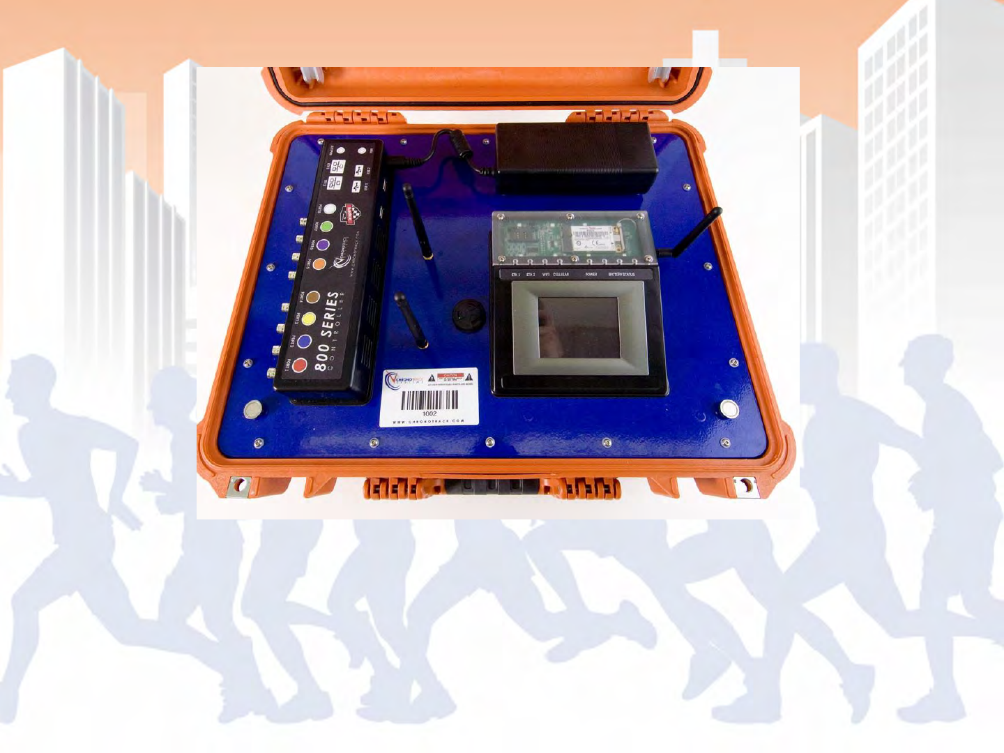
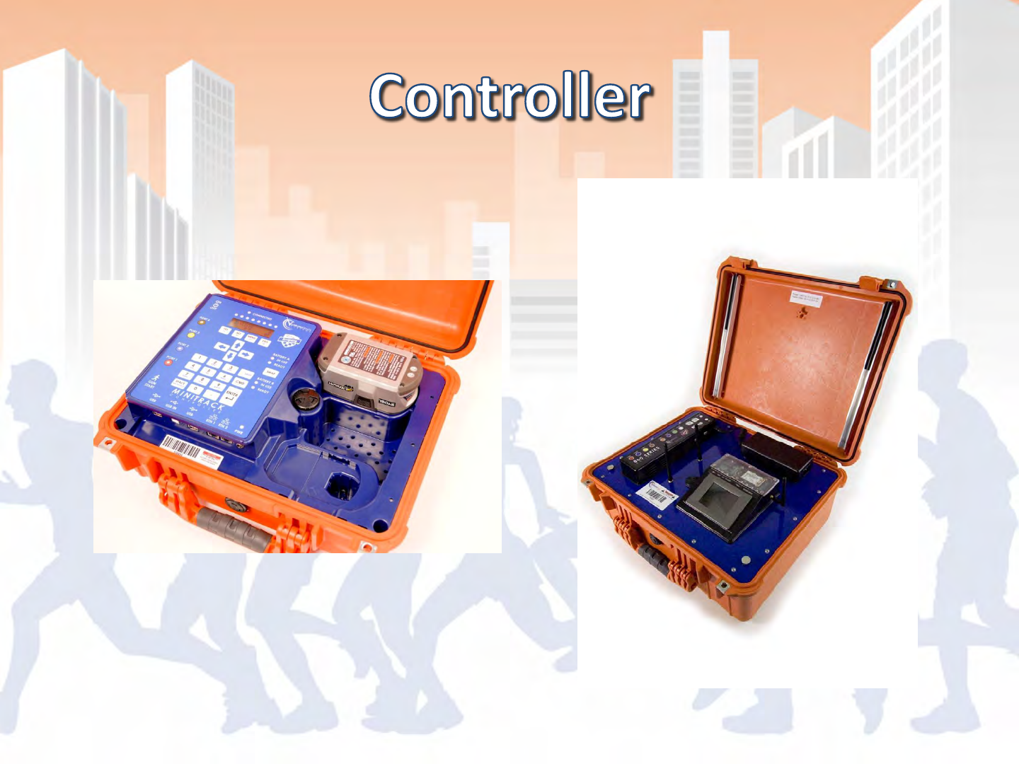
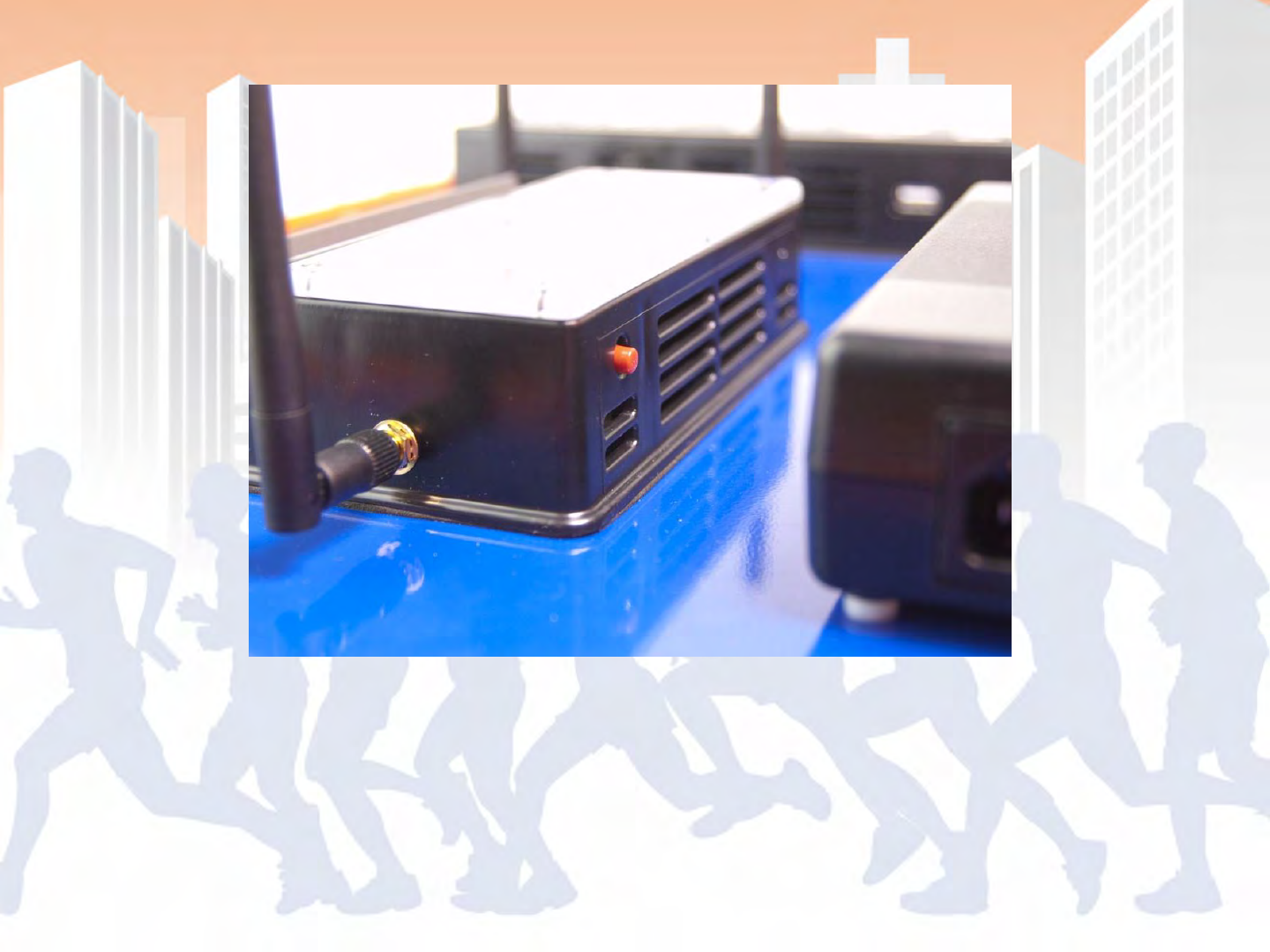
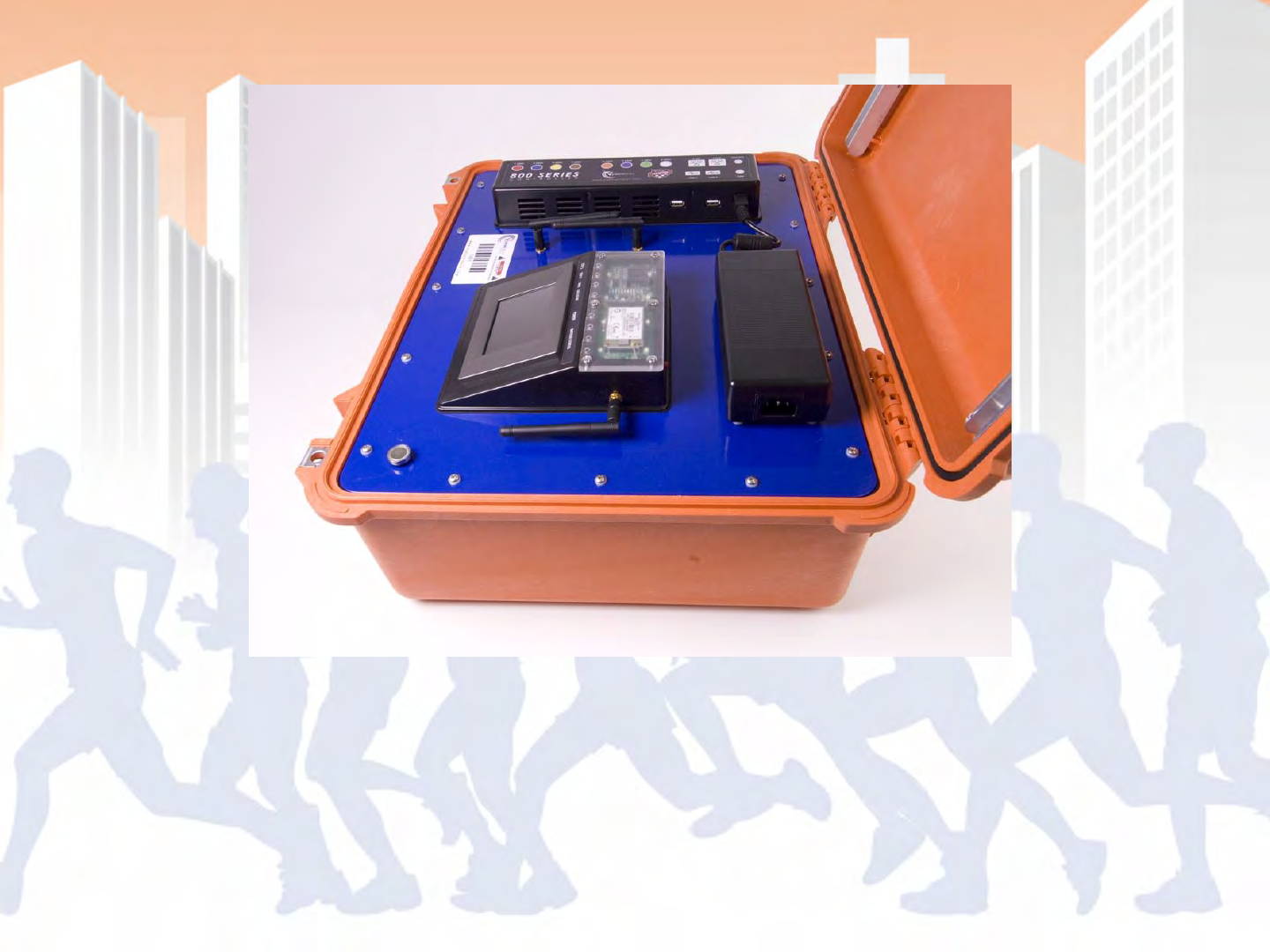
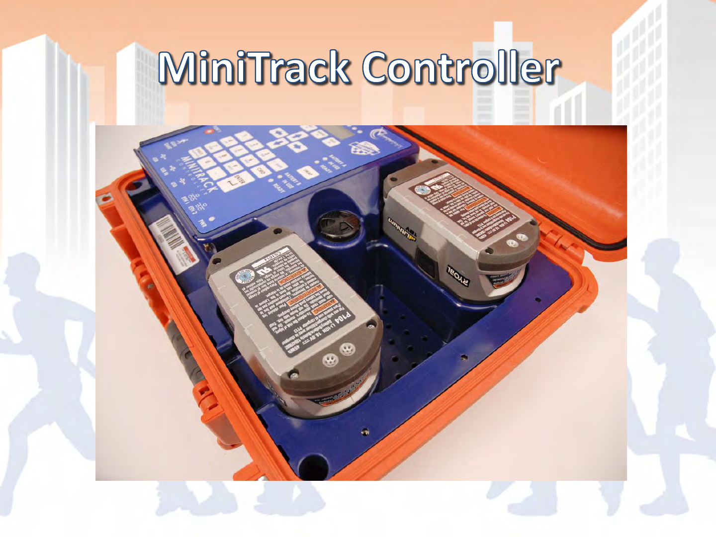
Controller
Three main components: Touch Panel Computer (TPC) Mesa, Connection
Mesa and the power brick . Beeper is located to the left of the TPC with
the WiFi Antennas.
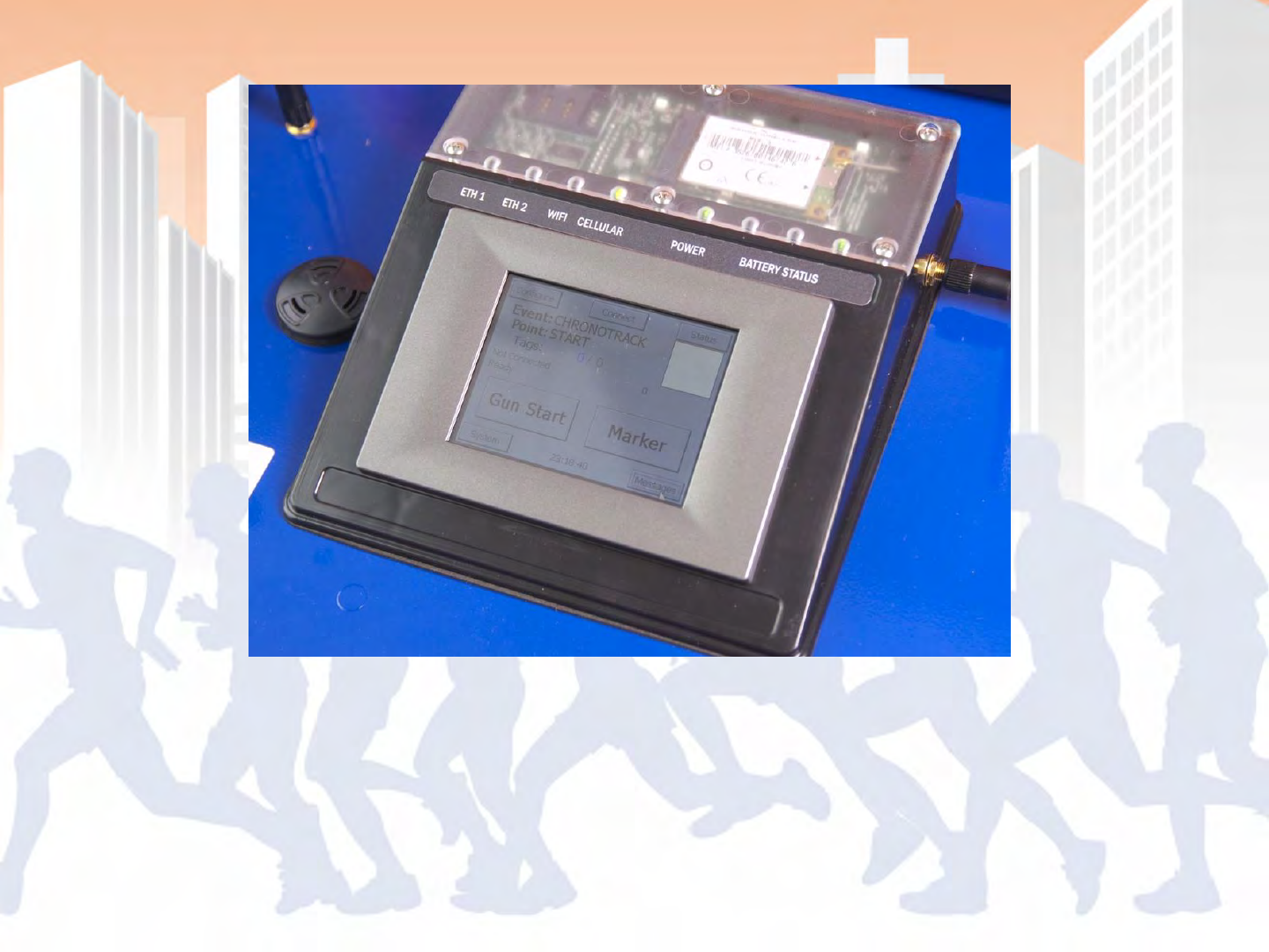
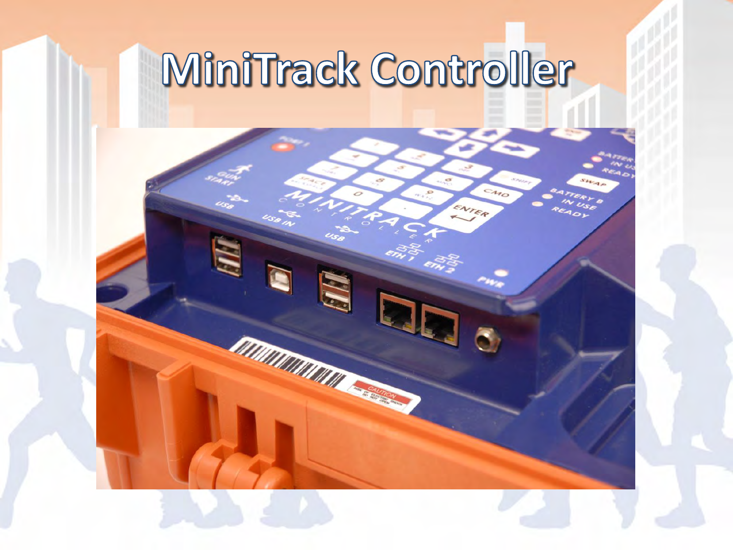
Touch Panel Computer (TPC) Mesa
Main interface, top clear panel to easily check for SIM card and status
lights. Cellular antenna connects to the right side of the TPC mesa.
Controller Power Button
Located on the back side of the TPC mesa
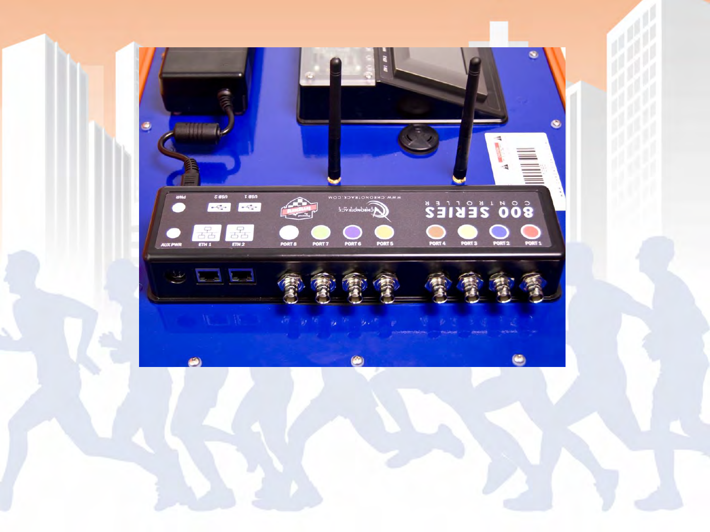
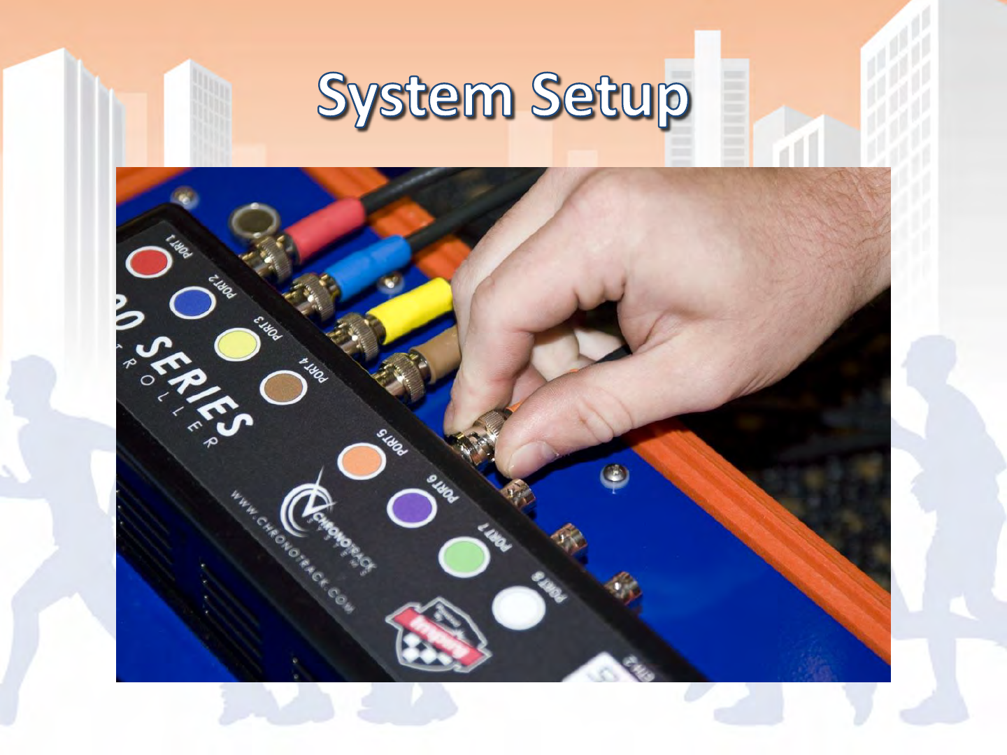
Connection Mesa
Color coded for antenna connections. Contains 2 LAN connections, 2 USB
ports, the aux power connection and makes the main power connection
from the power brick.
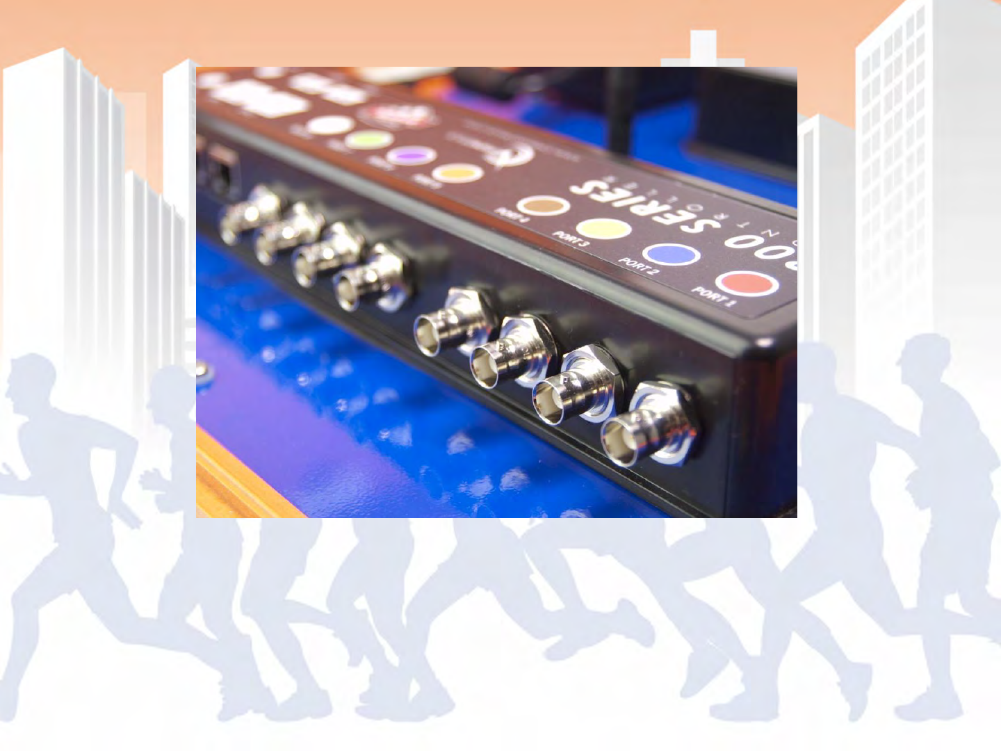
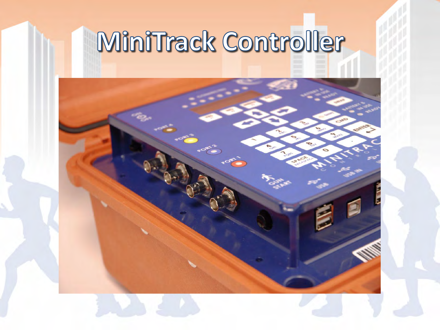
Antenna Connections
BNC and color coded, not required to match colors but best for
troubleshooting
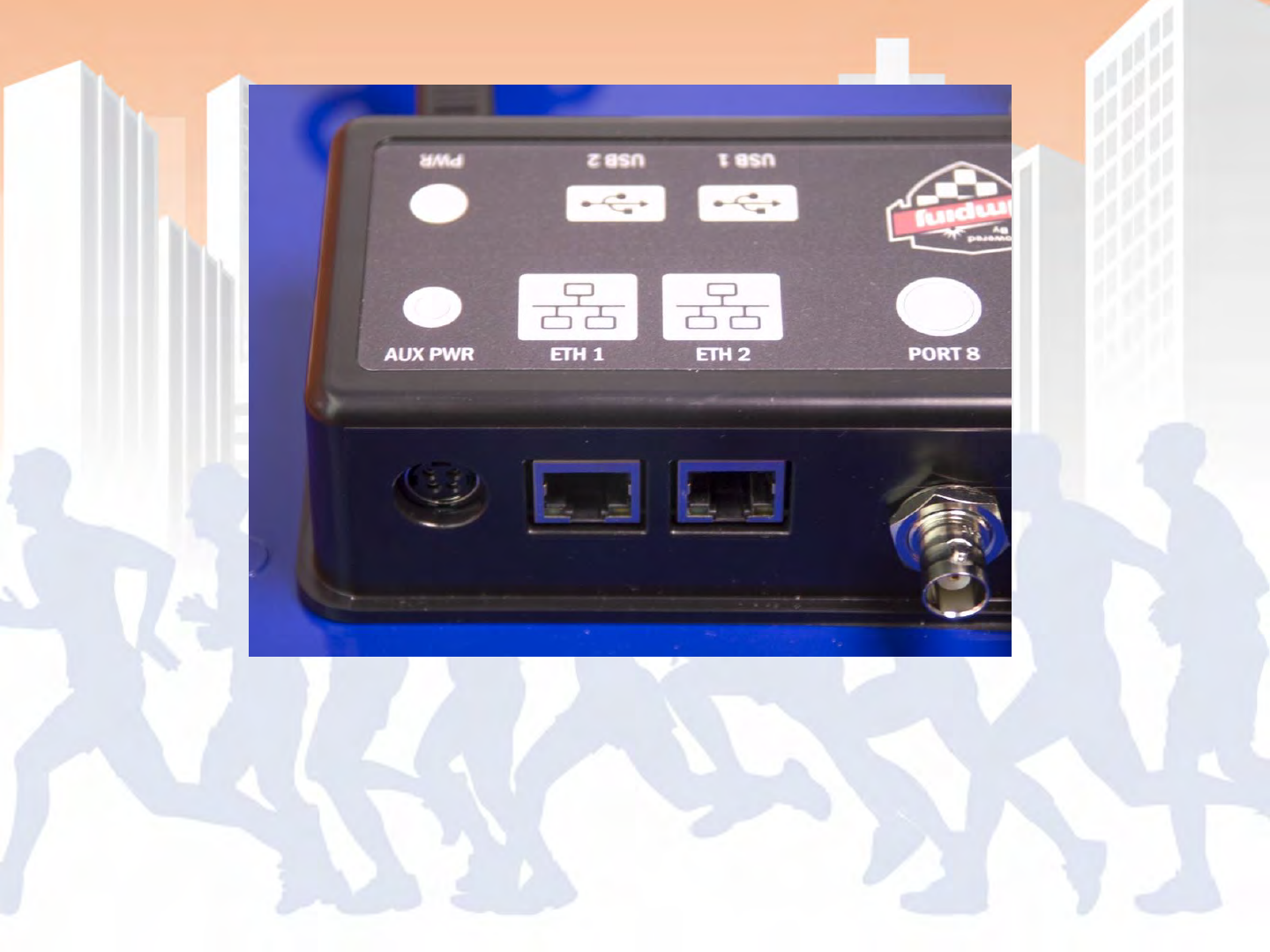
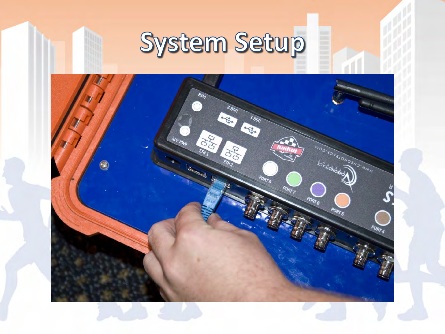
Aux Power and Ethernet Connections
Each controller has a 2 port Ethernet switch, uses standard network
cables. Auxiliary power connection for use with battery cable, supports
12-30V.
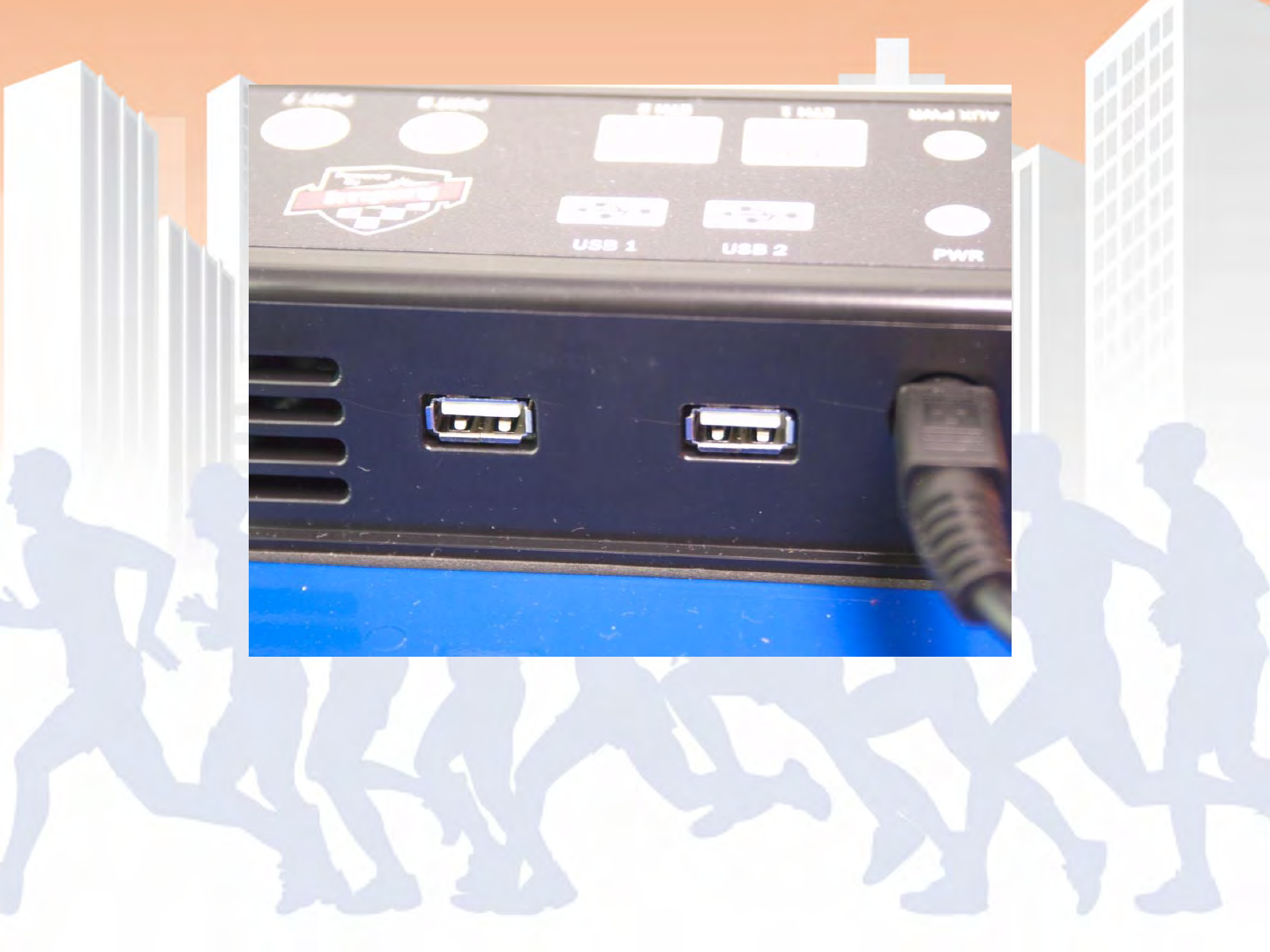
USB Connections
USB Ports are powered, however they do not support USB 2.0 – test
hardware before use for compatibility
AC connection on power brick
Located towards the back of the controller
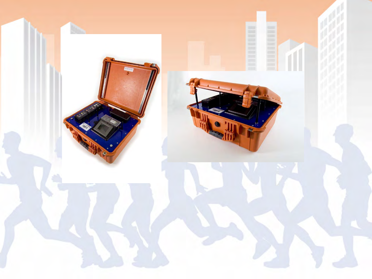
Magnetic Lid Props
Prevents lid from being slammed on cables, provides ventilation

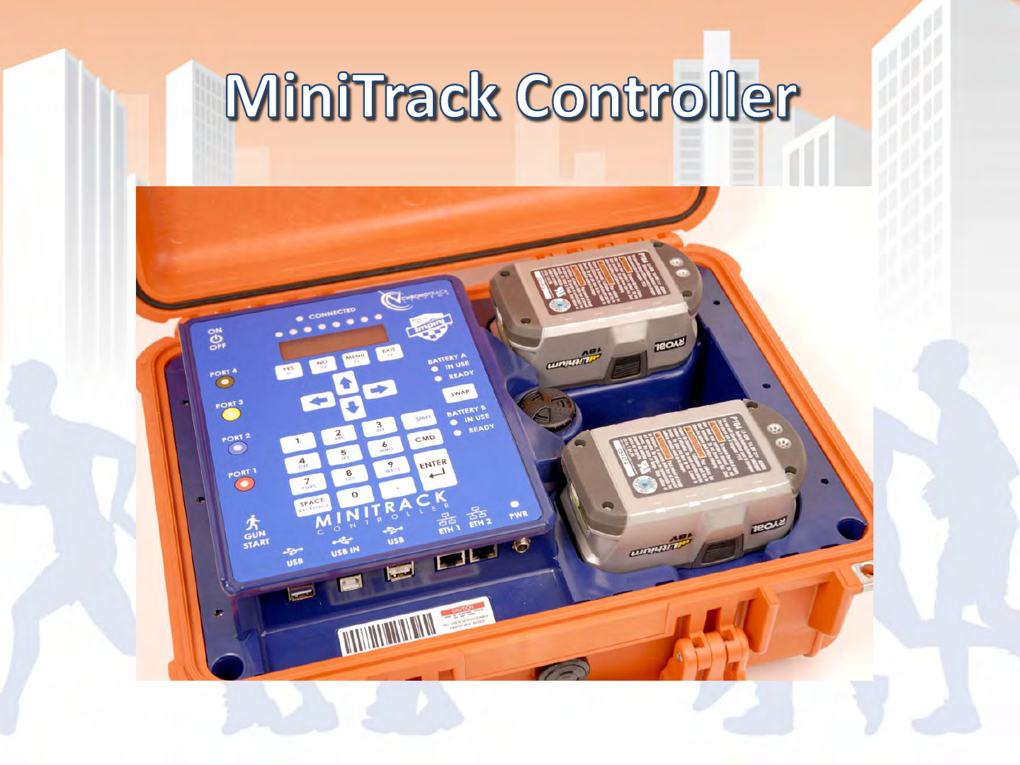
•Approximate weight: 16 lbs (with Batteries)
•Supports up to 14 ft timing lines per controller
•Communication via LAN
–Note: WiFi and Cellular available with add-on devices.
•Redundant Power: Operates on AC and Ryobi Drill
with seamless transfer
•Keypad interface.
•Does not require tuning, highly resistant to
interference
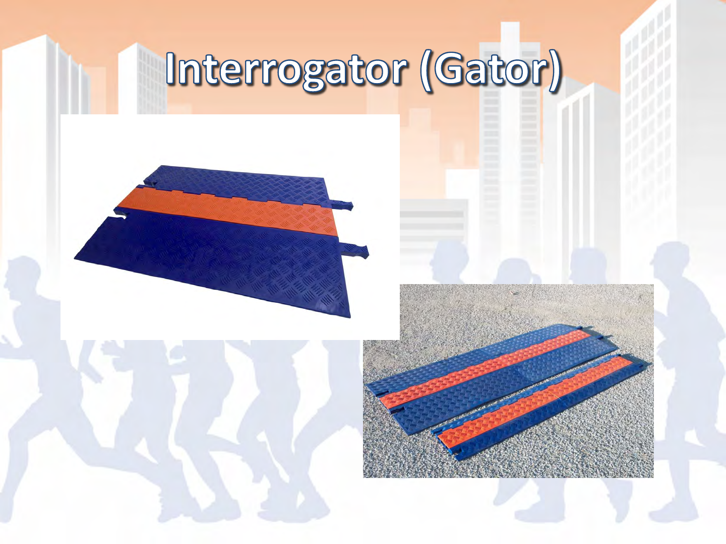

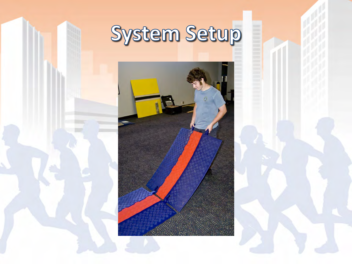
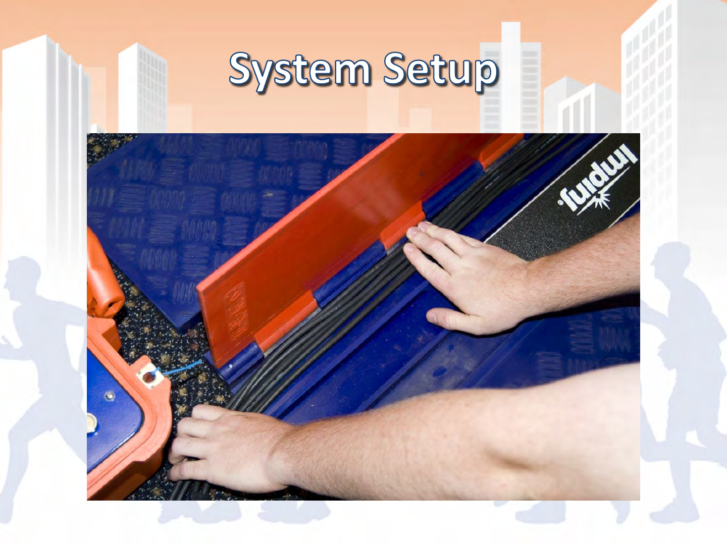
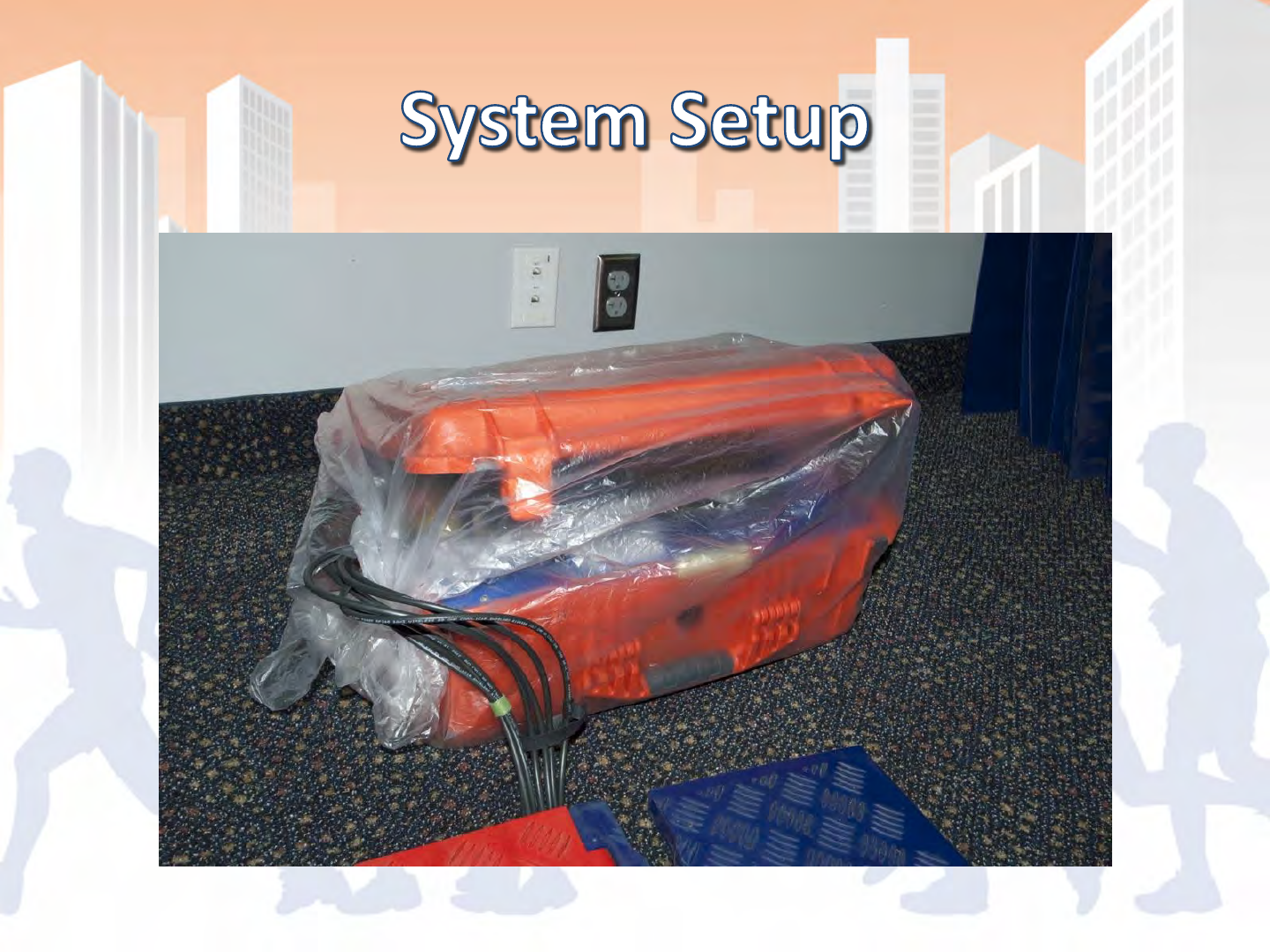
•Approximate weight: 27/12 lbs for Full/Mini
•Approximate length: 42/36” for Full/Mini
•Modular line configurations: Up to 56’ lengths
•Low profile, yet extremely rugged and durable
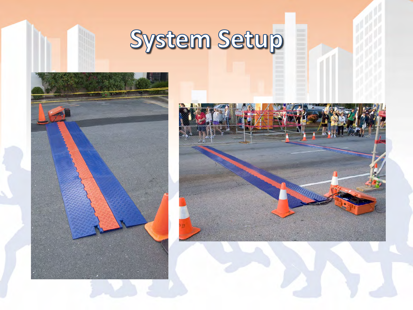
•Easy to handle and pack
•Can setup along side of the road and turn into
place for late road closures
•Strong enough to protect hardware and cables
even for large vehicles

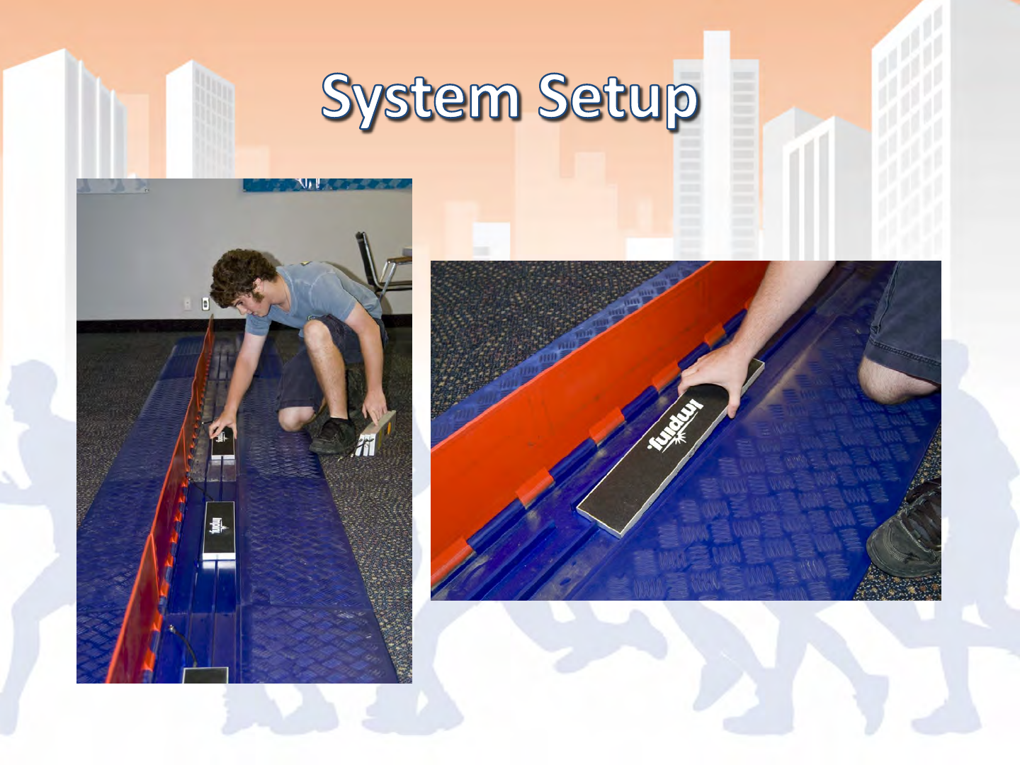
Interrogator (Gator)
Handle located on back side of gator
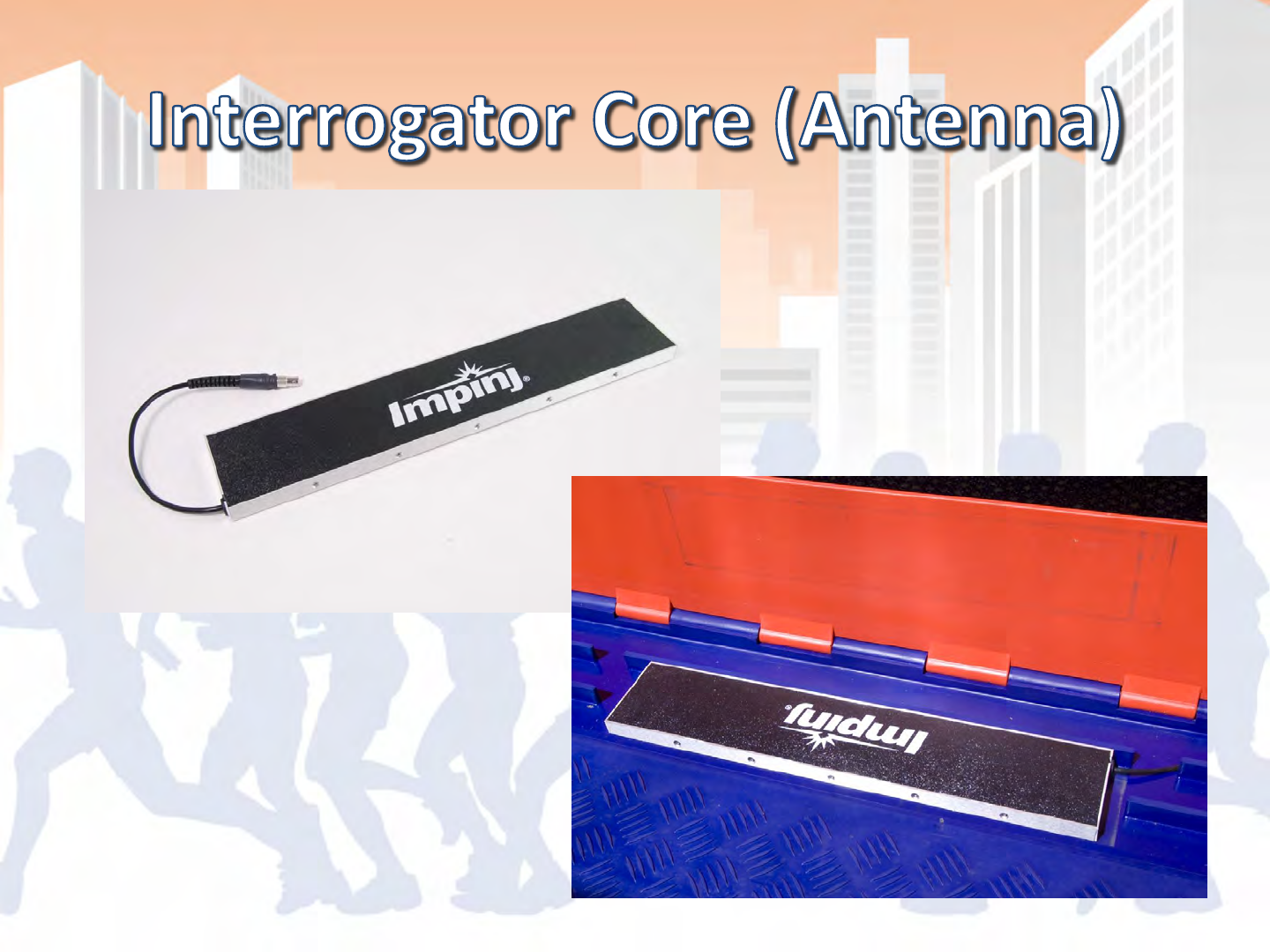

•Durable/rugged with replaceable pigtail cables
•Pigtails can be used to route cables in either
direction in the gator
•Separate component from gator so that if
damaged you don’t have to replace both at
the same time
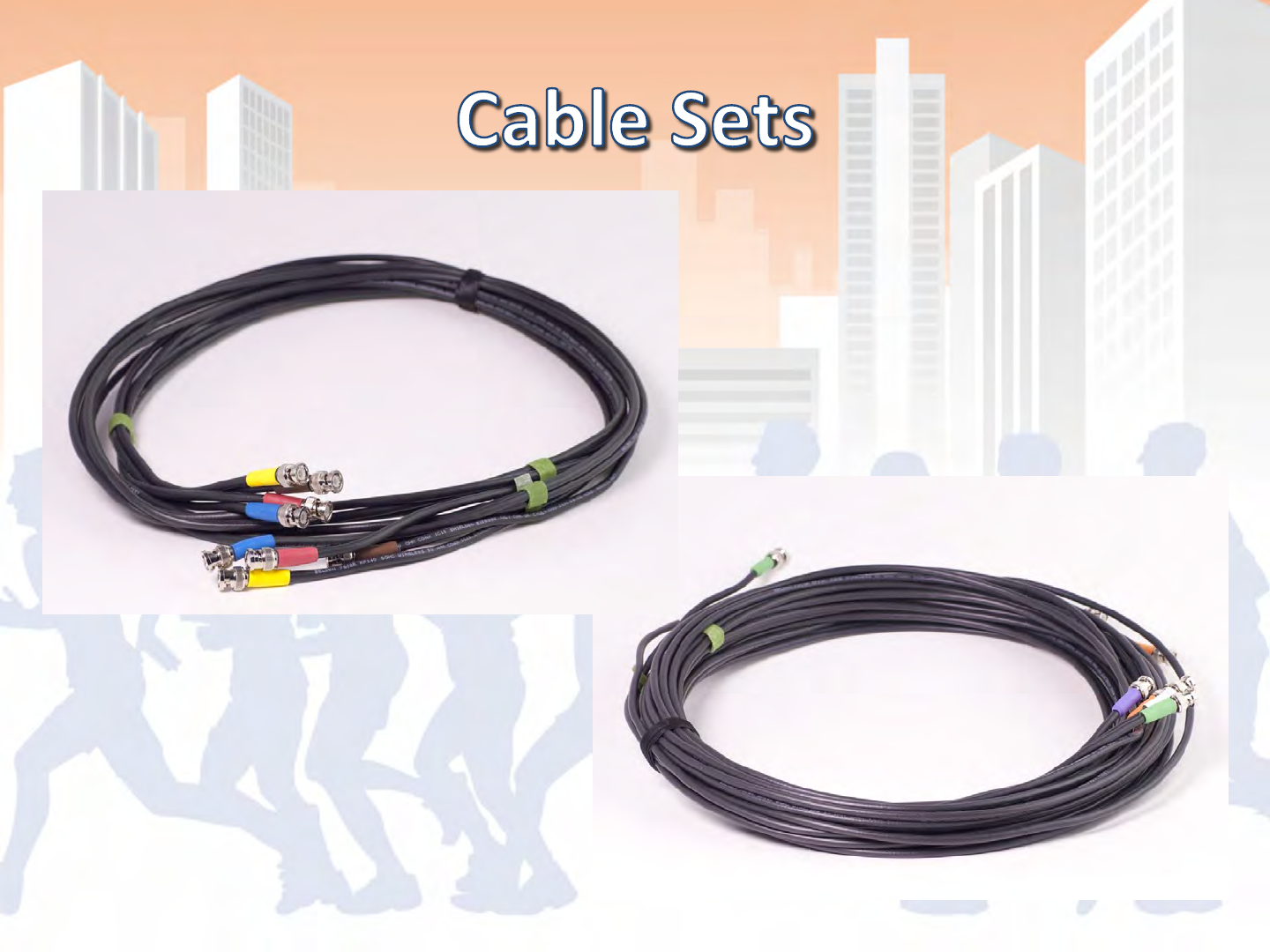

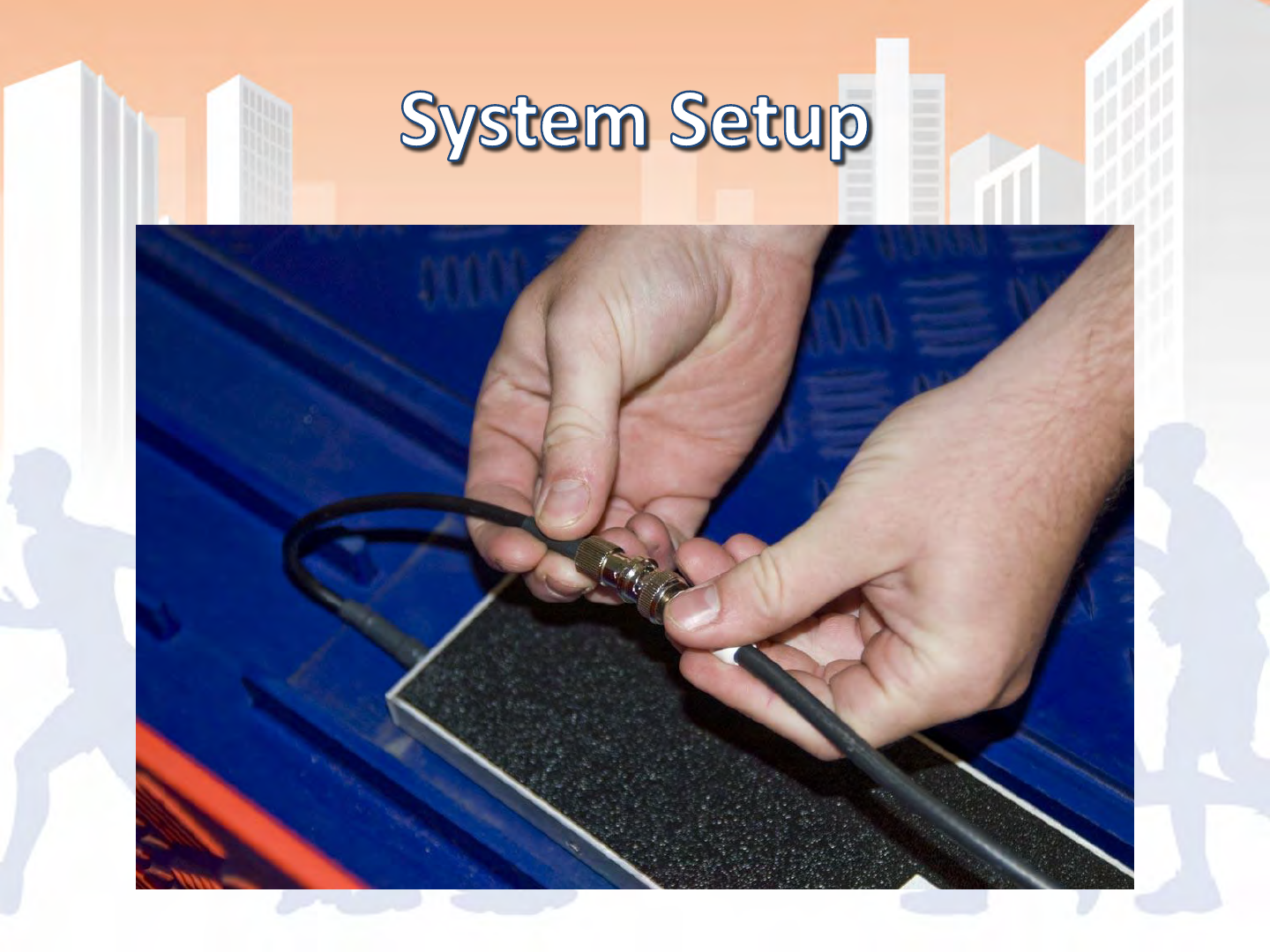
•High quality RF cable
•BNC for quick/easy setup
•Color coded and bundled in sets of 4

•CAUTION – Any changes or modifications to this
system without the express permission of
ChronoTrack Systems will void the user’s authority
to operate this equipment.
•As a professional installer you must:
–Use only ChronoTrack approved antennae
–Use only ChronoTrack approved cables
–Use only ChronoTrack approved accessories

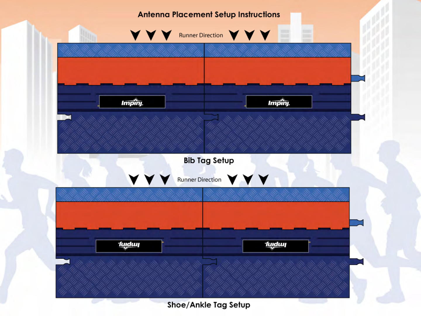

•Read-zone: begins around two meters in front
of the line
•Reads tags repeatedly over a 5 second time
period
•Only reports a single time in the 5 second
window, when it “best” saw the tag

•Not collecting tags at the end of the race,
creating additional reads as finishers collect at
timing points to cheer on or wait for other
participants
•Unique lines within a close proximity of each
other require shielding from each other

•Instructional materials: flyers and videos
•ChonoTrack Timers Web Portal
•Manual and Guides


- BoxScore’s Main Screen
- Configuring the controller for your event
- Set and sync times
- Removing data with a thumb drive
- Error alerts
- Sample race
- Advanced modes and features

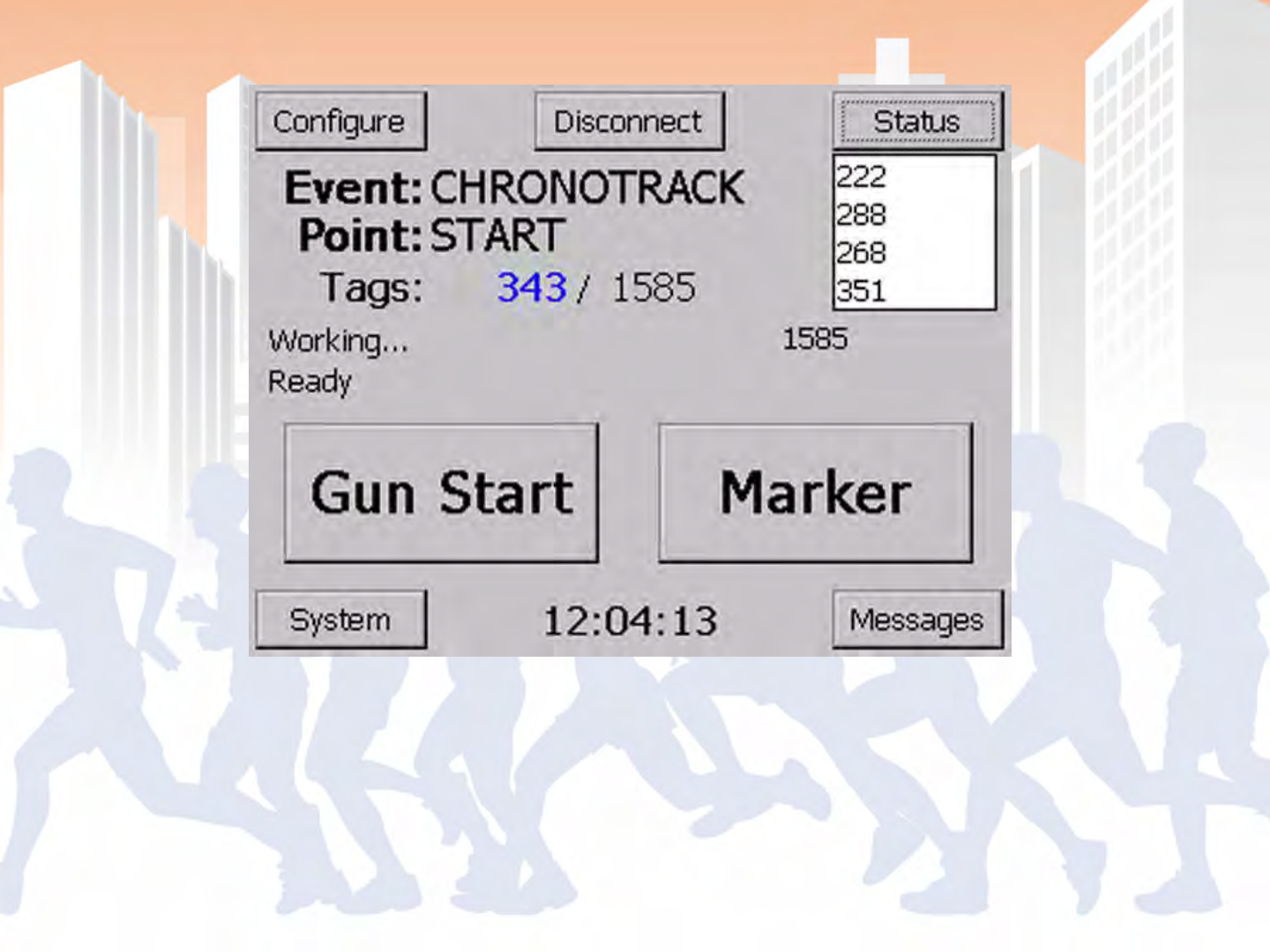
BoxScore - Main Screen

BoxScore – Point Configuration
On startup and accessible in the Configure menu

•Time sets go out to all controllers on the
wired/wireless network
•Can either set a new time or set the current
time
•Best to set the controllers to another source,
time resolution on controller display will be
less accurate
•Controllers should be left one once time is set

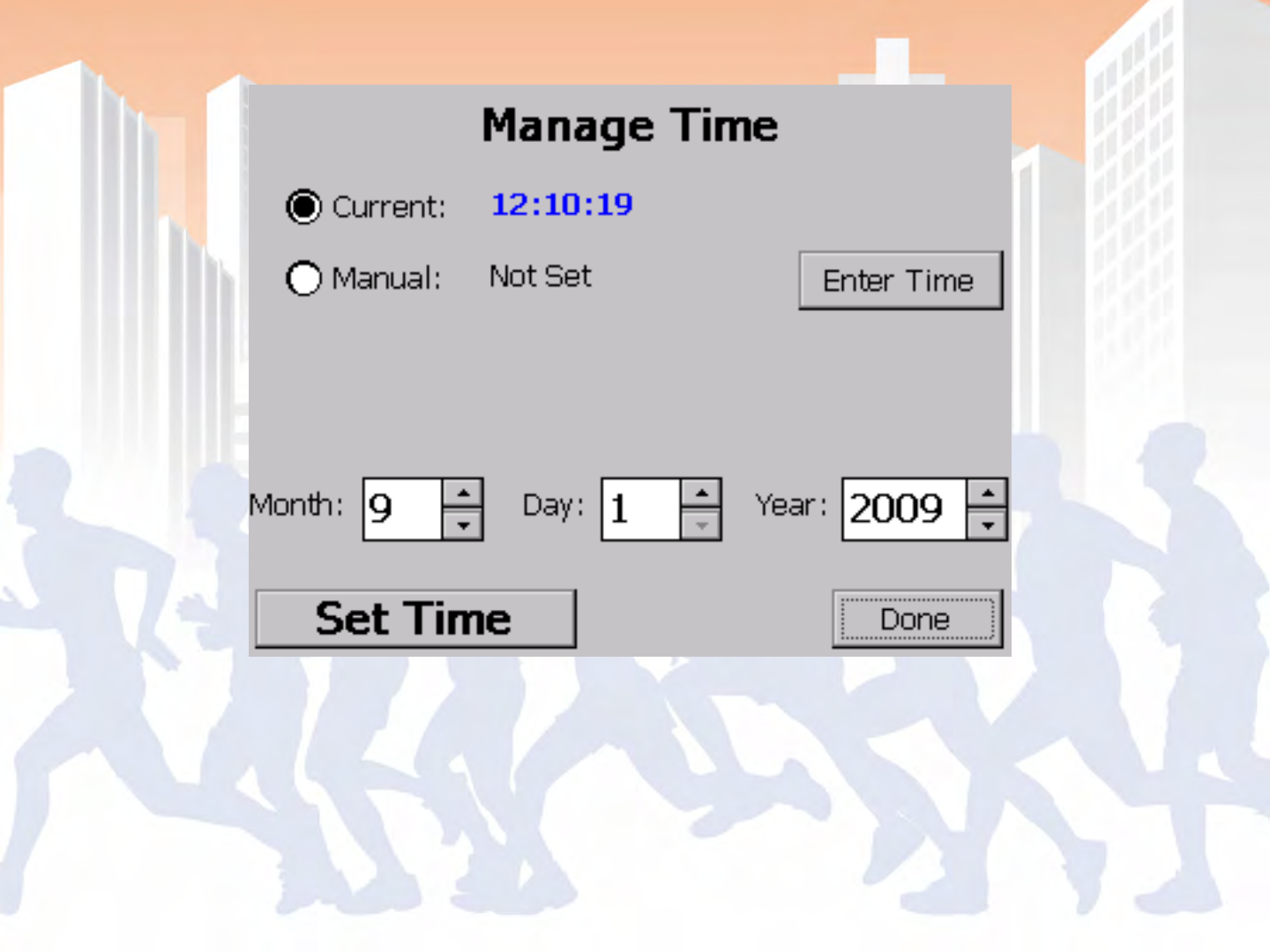
BoxScore – Time Management
Accessible via the System menu

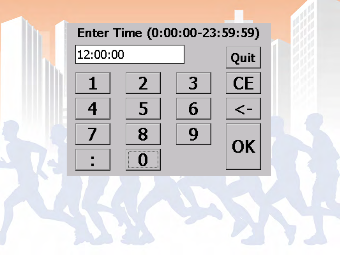
BoxScore – Time Entry Screen

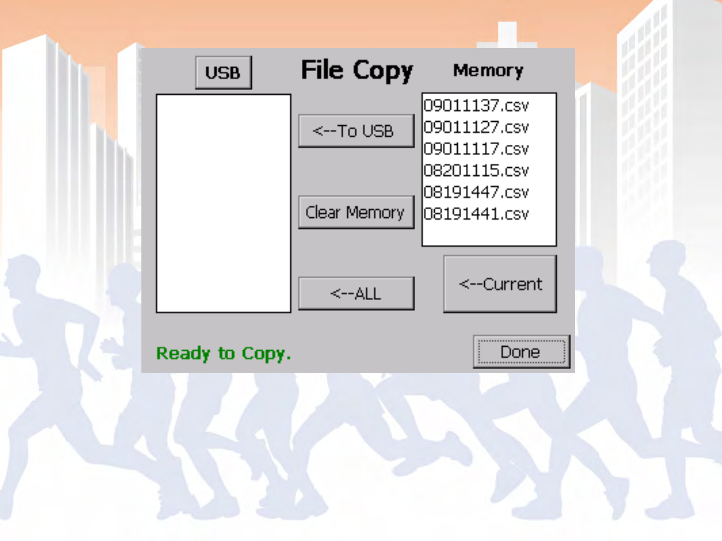
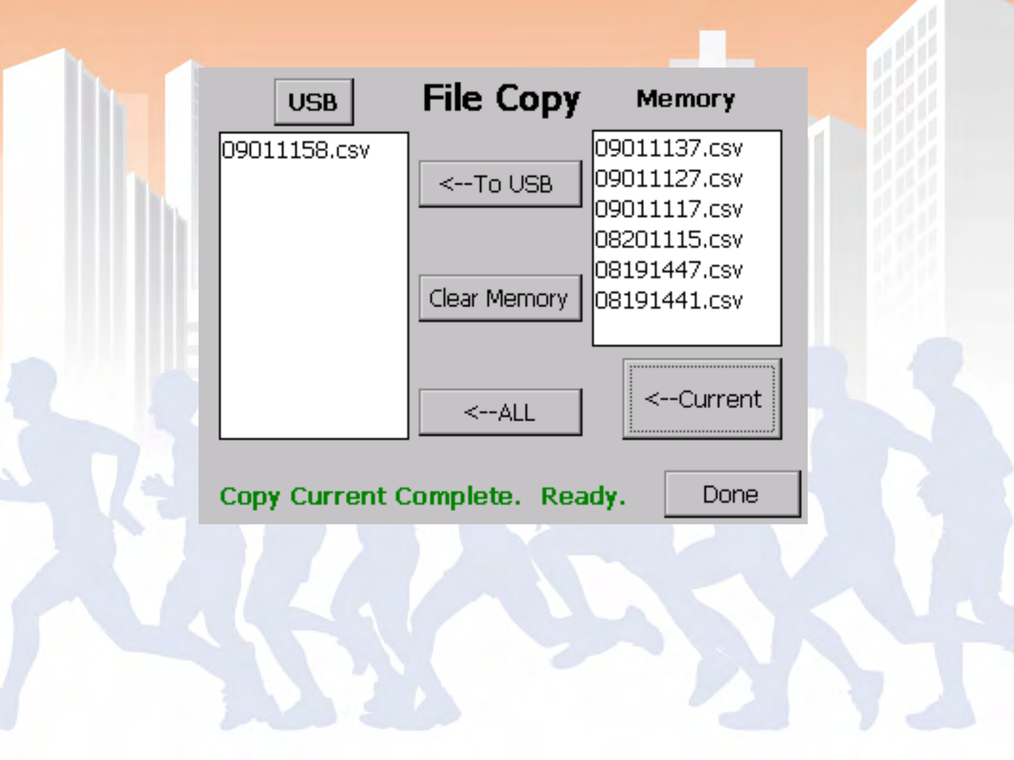
•Controller saves data to a single file from
power on to off
•Use thumb drives under 2 gigabytes (larger
USB drives take to long for the OS to index)
•Data is saved to a folder based on the current
point name with a file name based on the
power up time

BoxScore – File Copy

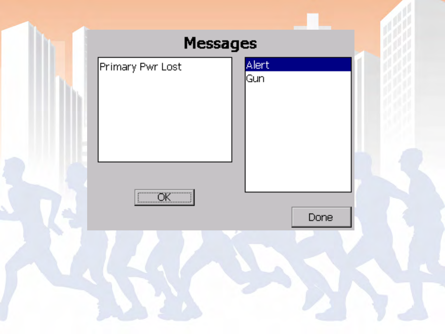
•Examples: Power loss, Time discrepancy,
Disconnected Hardware, Out of Date Software
•Tracks gun start times and marker times
•Must acknowledge errors

BoxScore – Messages

•Power on
•Configure or confirm point config
•Set time
•Press gun start on start
•Change point name from start to finish before
finishers return
•Collect data and remove after race
•Process data in SimpleClient and Scoring software

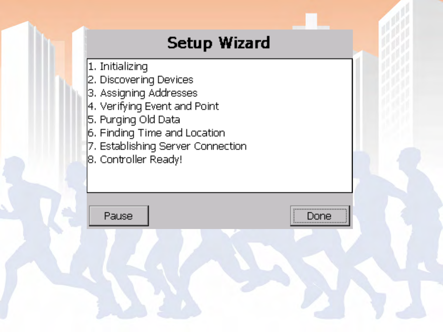
BoxScore – Setup (Start-up) Wizard
Point Config screen comes up after step 5

BoxScore – Point Configuration

BoxScore – Time Management
Accessible via the System menu

BoxScore - Main Screen

BoxScore – Point Configuration
BoxScore - Main Screen
BoxScore – File Copy

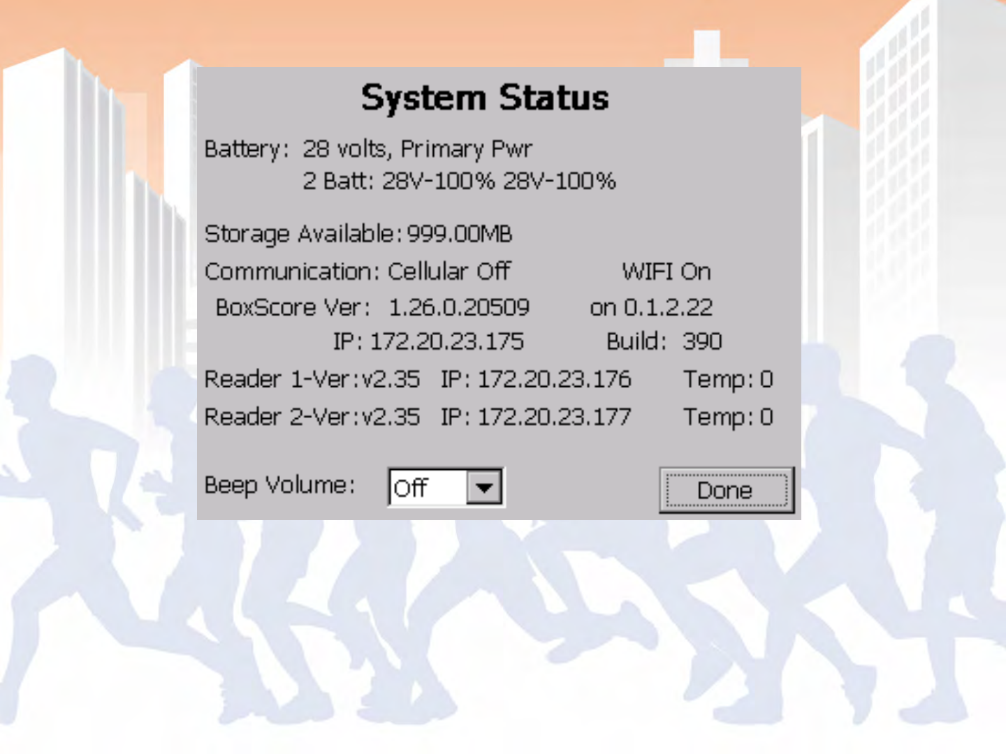
•Battery status
•Versions
•Connection Status

BoxScore – System Status
Status > System
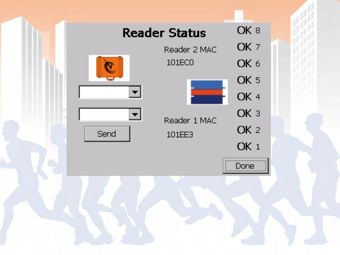
BoxScore – Reader Status
Status > Point


•Power Controller ON
•Configure/Confirm Point Configuration (Point
should be set to start)
•Set (or sync) Times
•Read Tags (Athletes crossing the line before
the race)
•Gun Start
•Read Tags (Athletes beginning the race)

•Change Point from ‘Start’ to ‘Finish’
•Read Tags (Runners Finishing)
•Remove Data using USB Drive
•Open File in SimpleClient
•Select the start session apply your gun start time,
play session and save data
•Select the finish session apply your gun start time
from start session, play session and save data


BoxScore - Main Screen
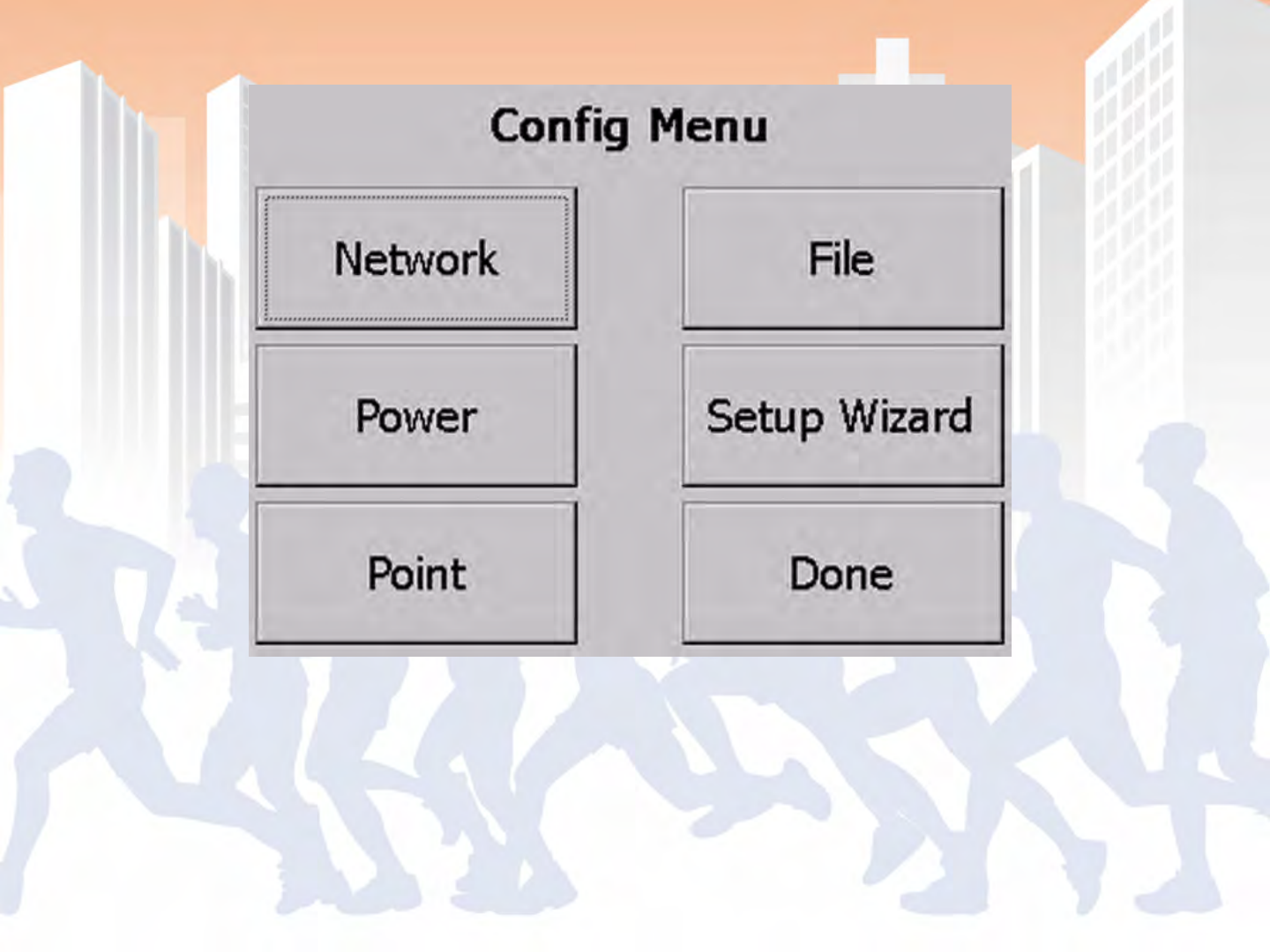
BoxScore – Configure Menu
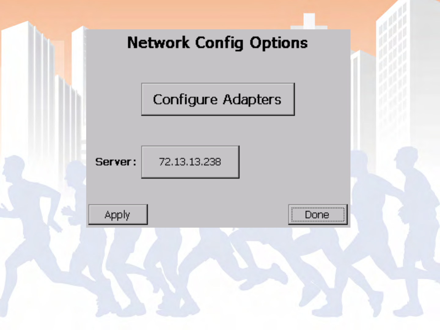
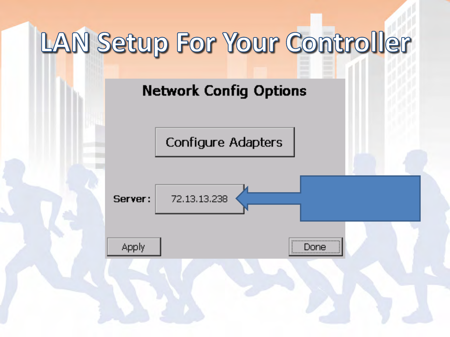
BoxScore – Network Configuration Options
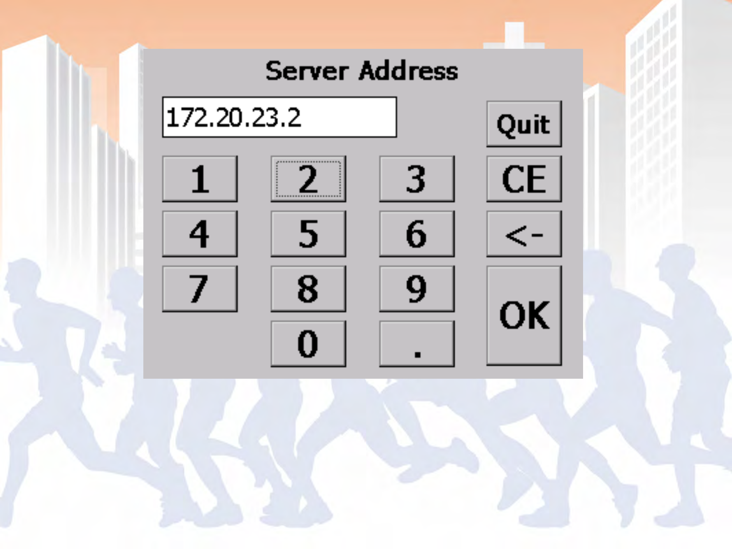
BoxScore – Server Address Entry
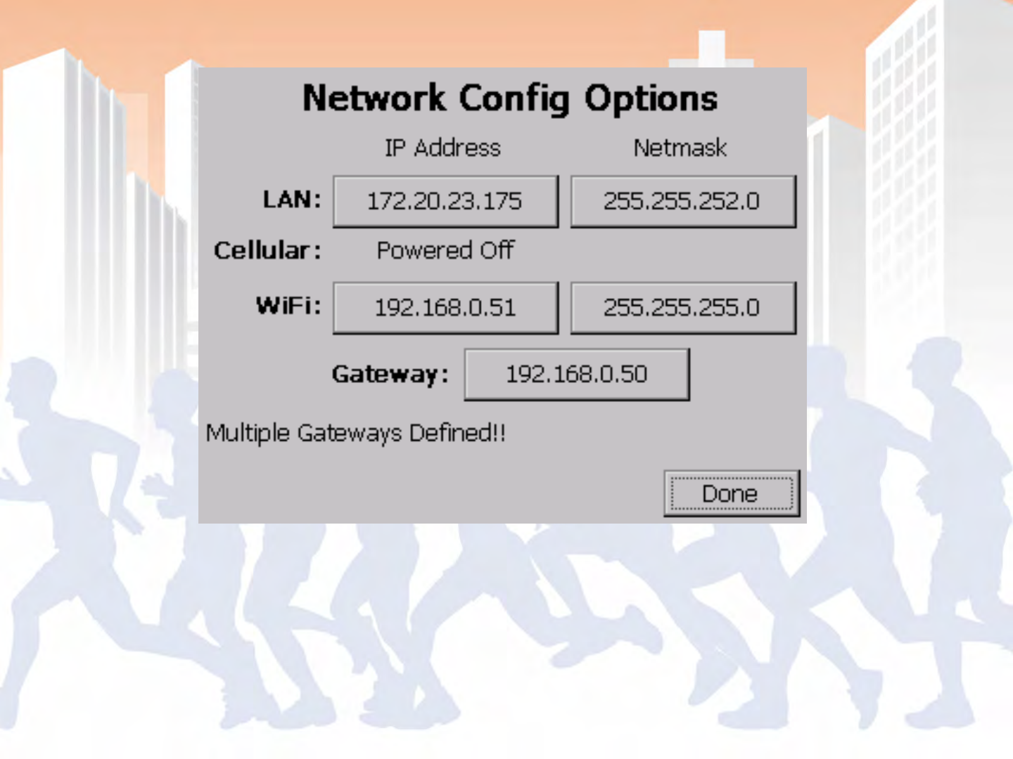
BoxScore – Advanced Network Options
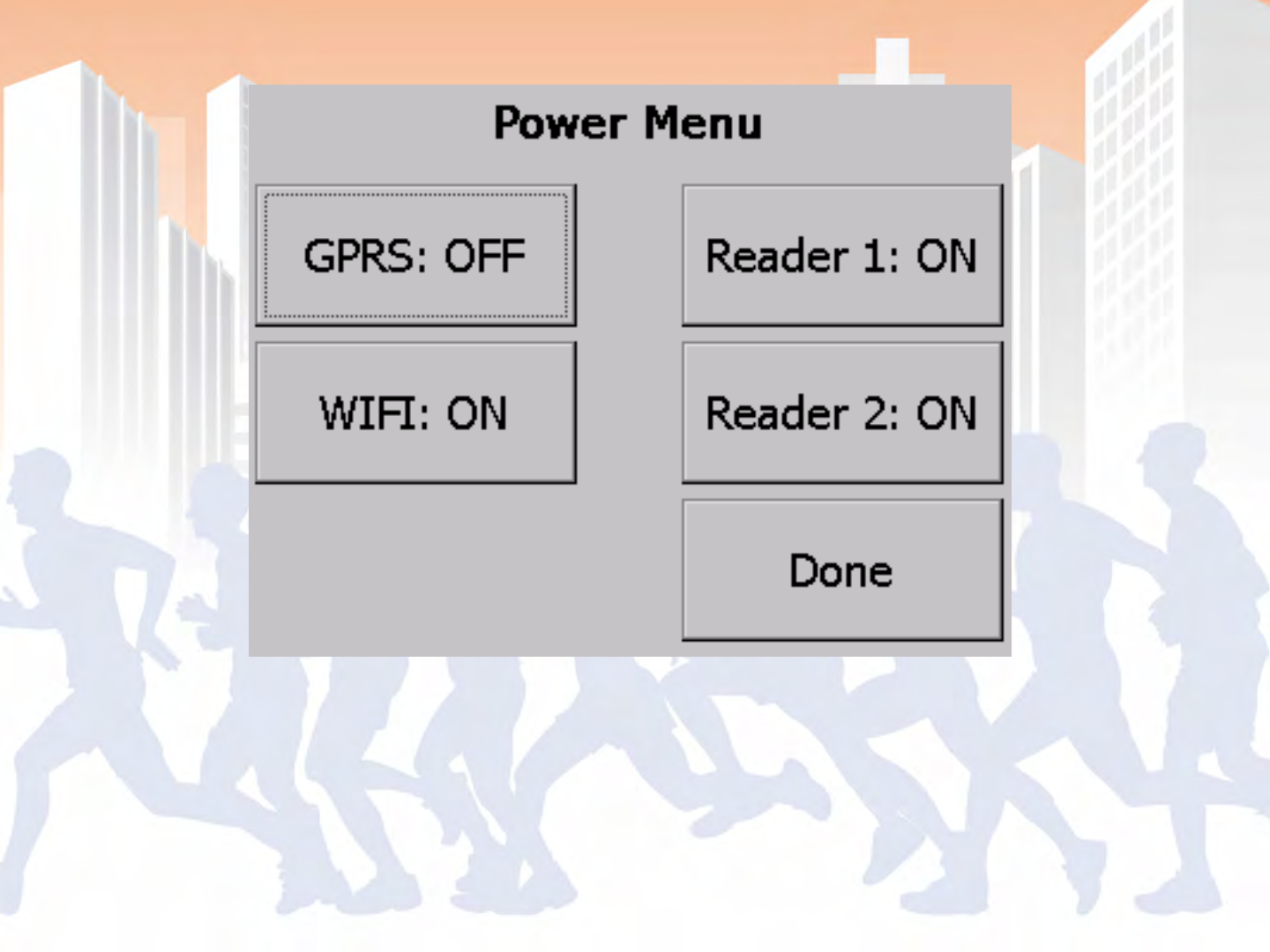
BoxScore – Power Menu
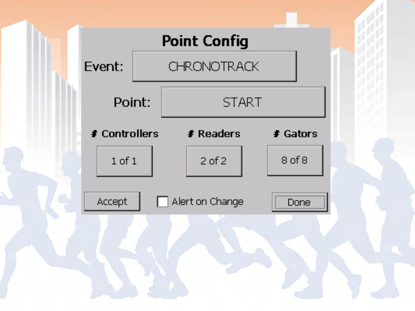
BoxScore – Point Configuration
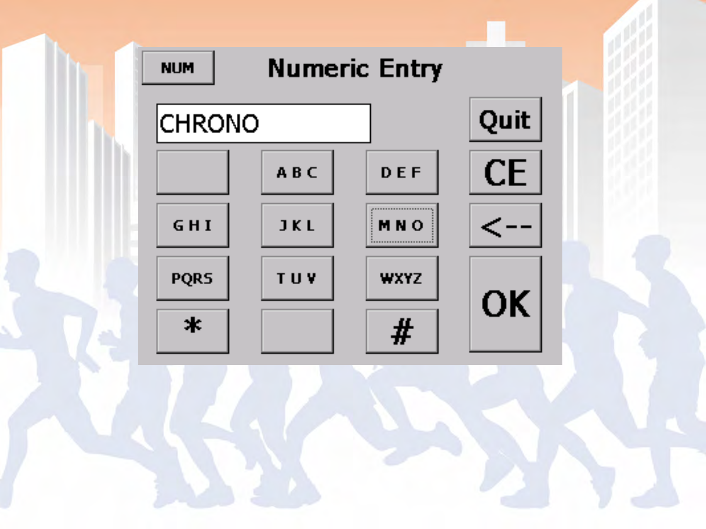
BoxScore – Input Screen (Alpha)
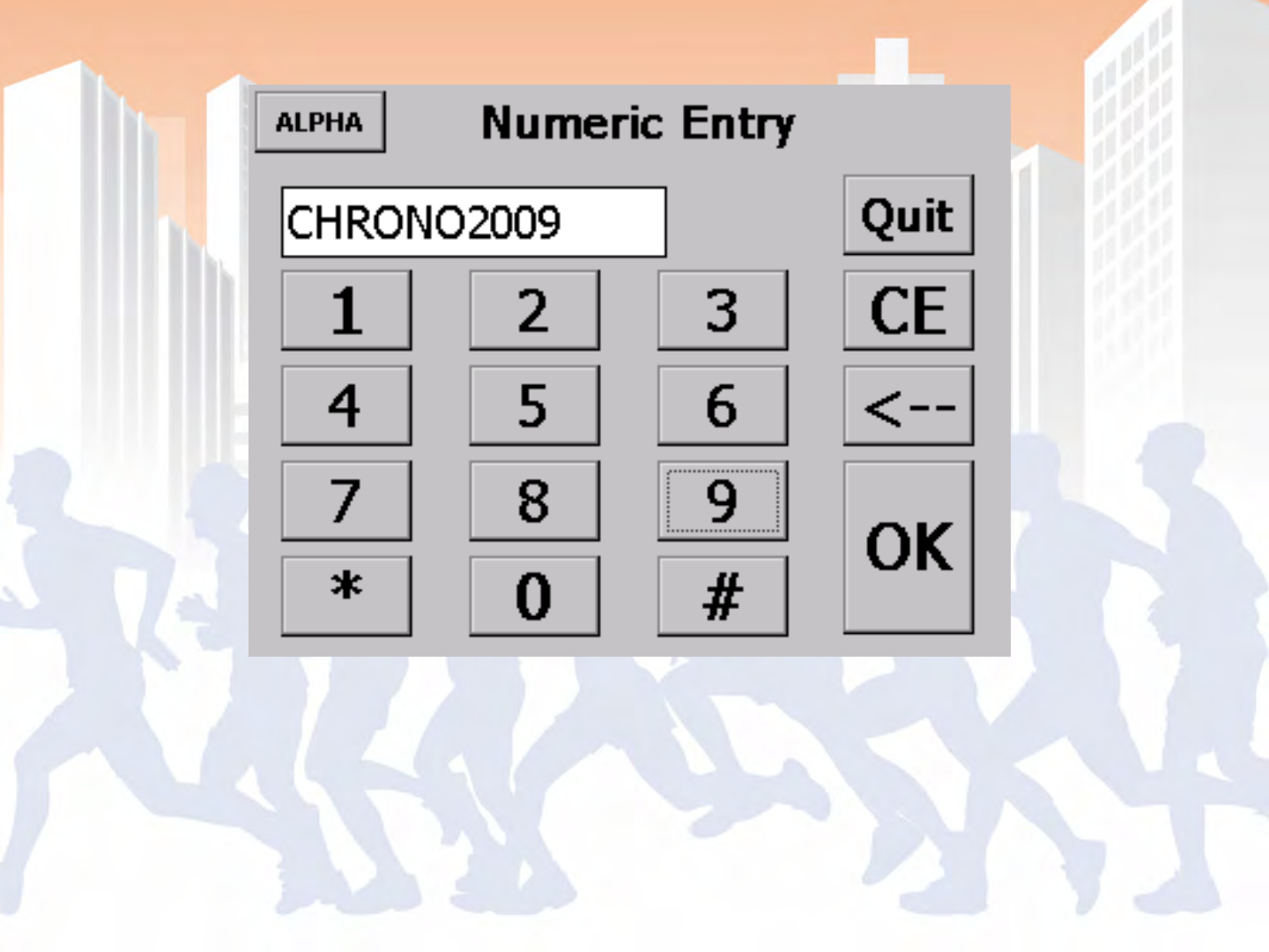
BoxScore – Input Screen (Numeric)

BoxScore – File Copy
BoxScore – File Copy
BoxScore – Setup (Start-up) Wizard
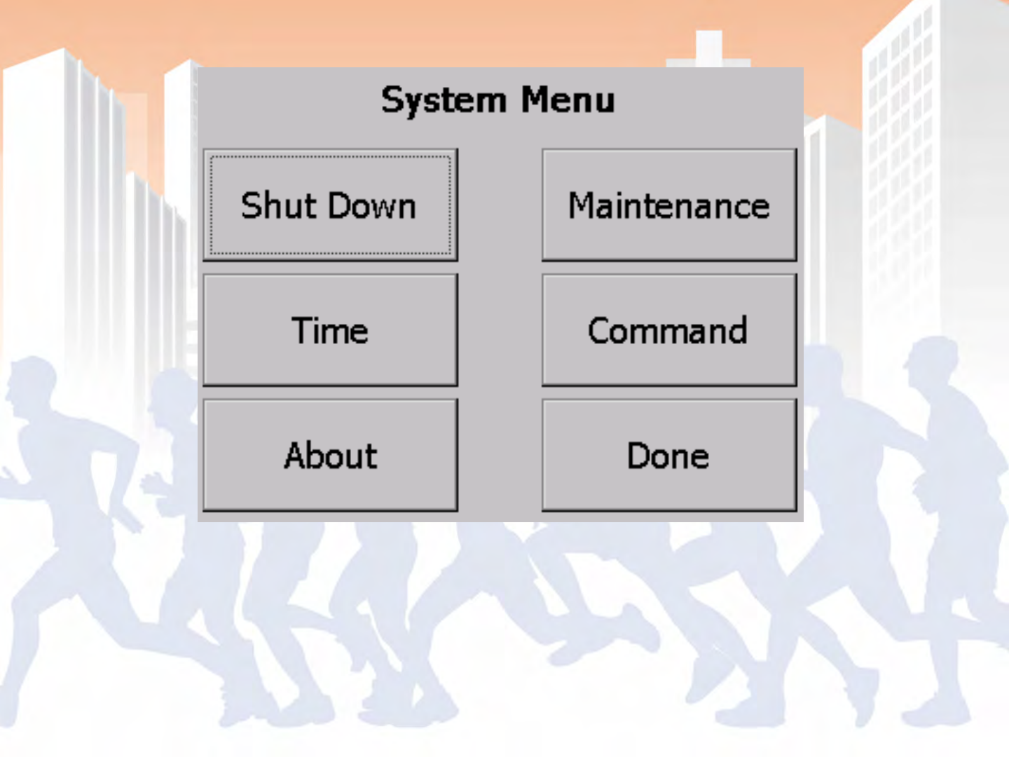
BoxScore – System Menu
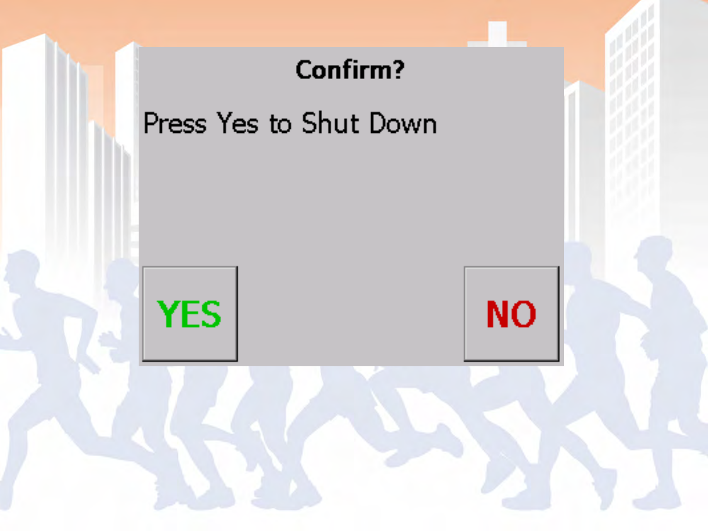
BoxScore – Shut-down Confirmation
BoxScore – Time Management
BoxScore – Time Entry Screen
BoxScore – About
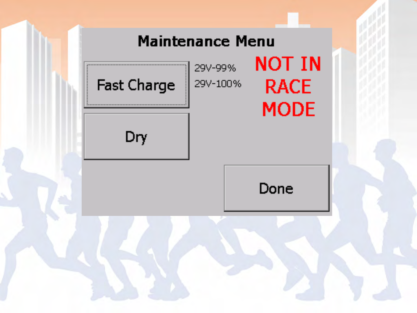
BoxScore – Maintenance Menu
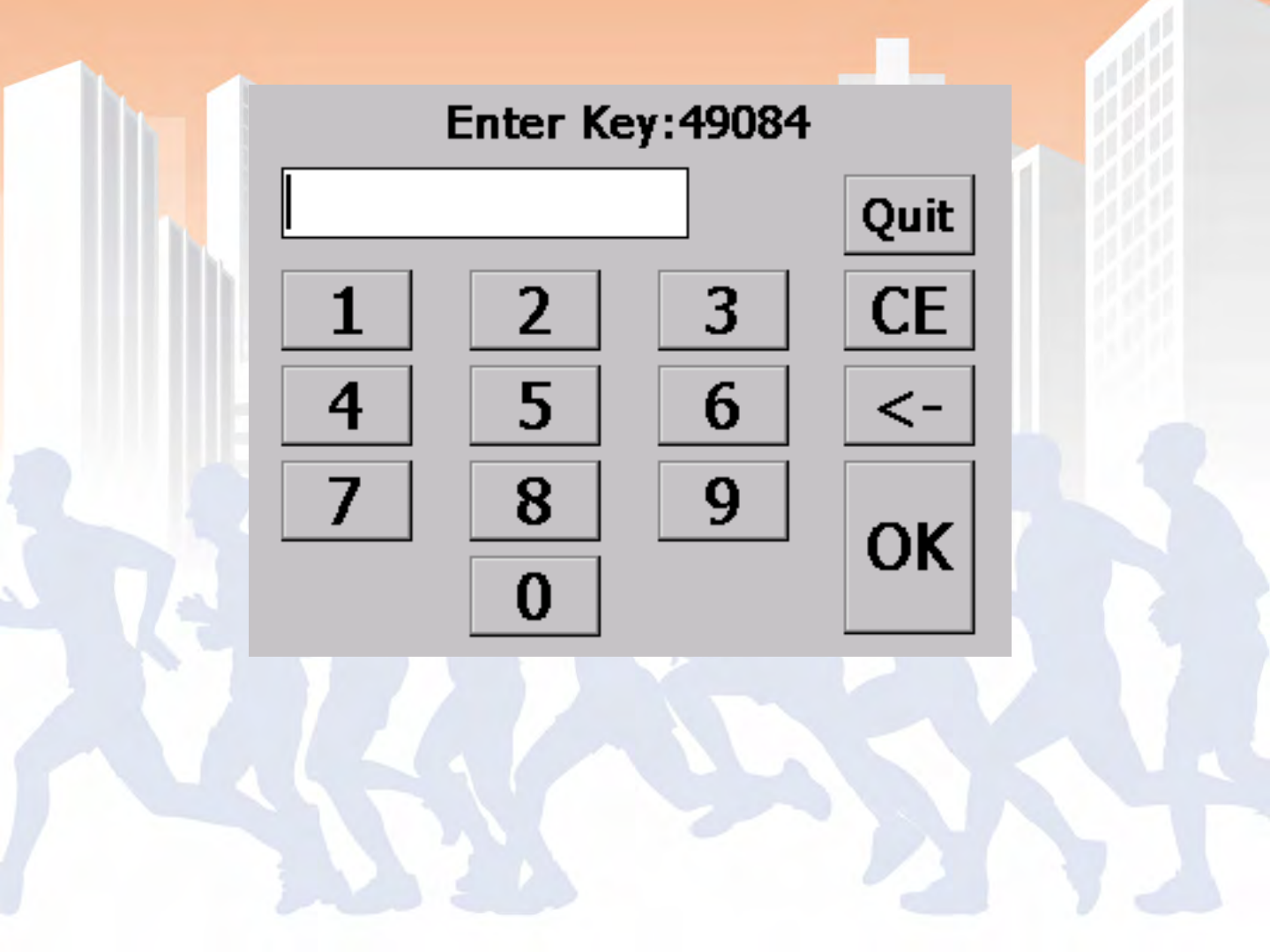
BoxScore – Command Key Entry
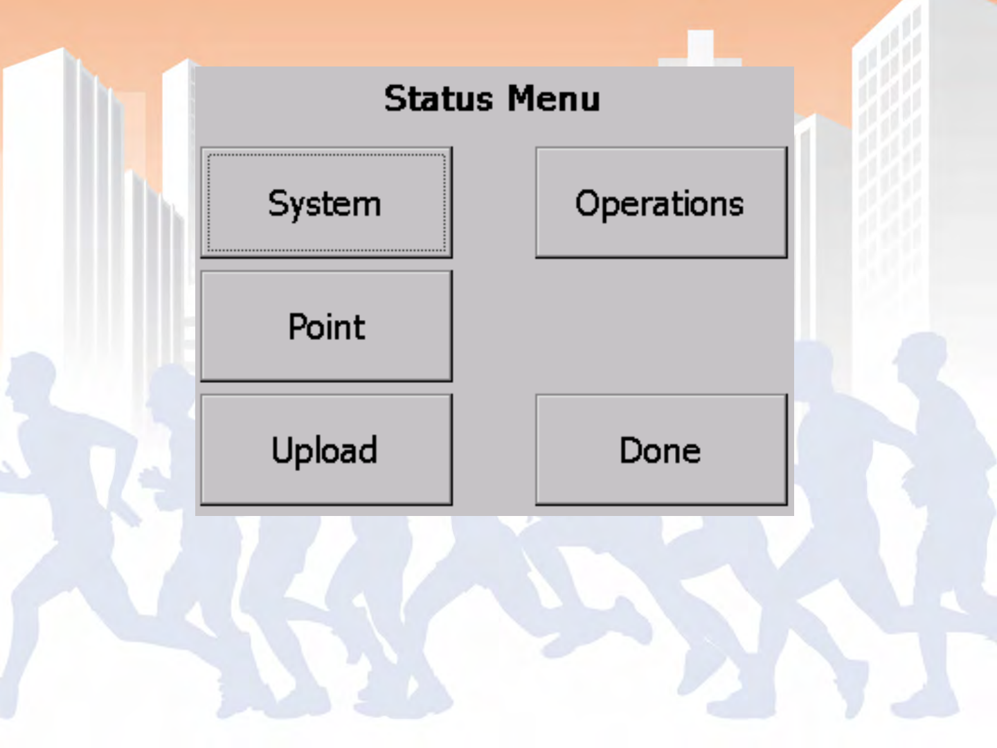
BoxScore – Status Menu
BoxScore – System Status

BoxScore – Reader Status
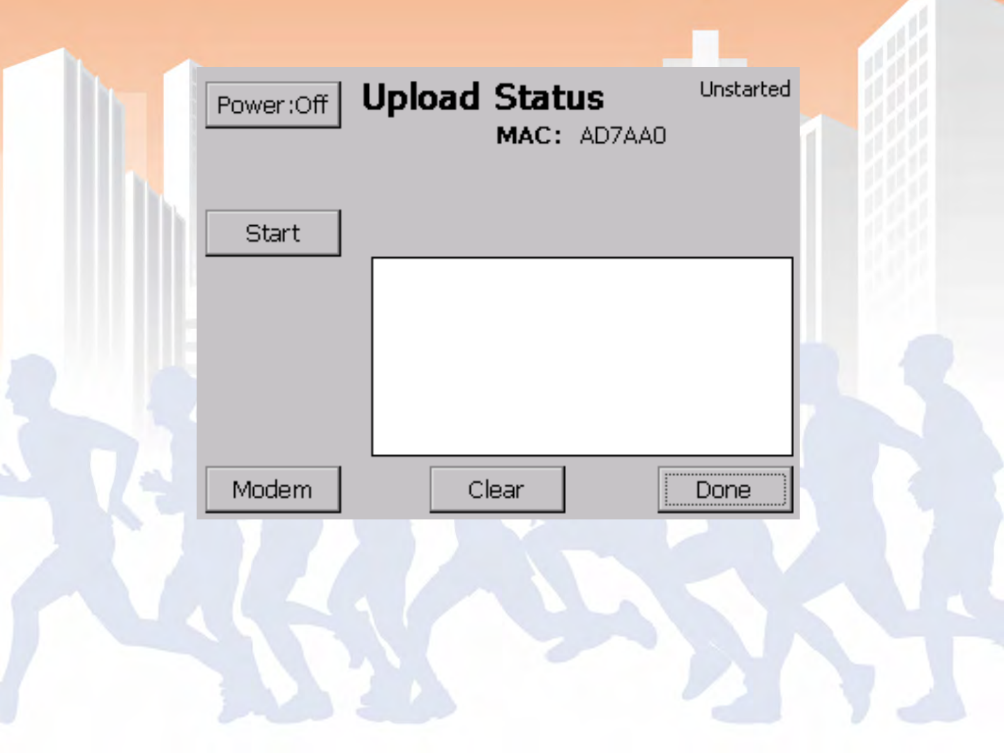
BoxScore – Upload Status
BoxScore – GPRS (Cellular) Connect
BoxScore – GPRS (Cellular) Connect
BoxScore – GPRS (Cellular) Connect
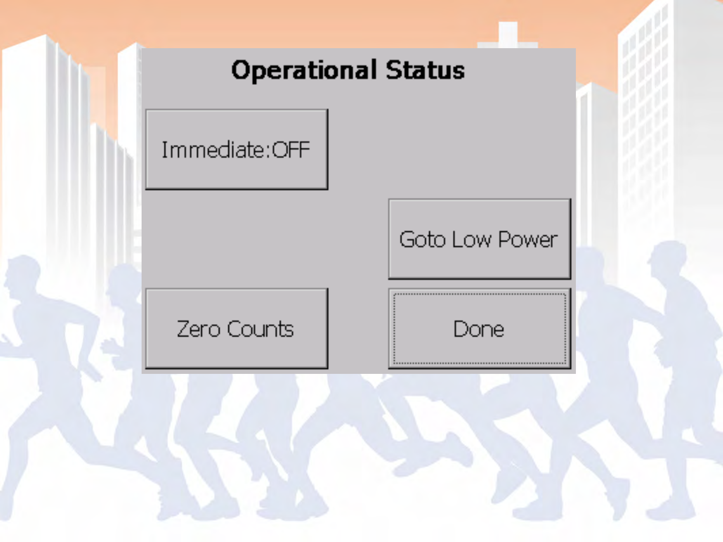
BoxScore – Operational Status
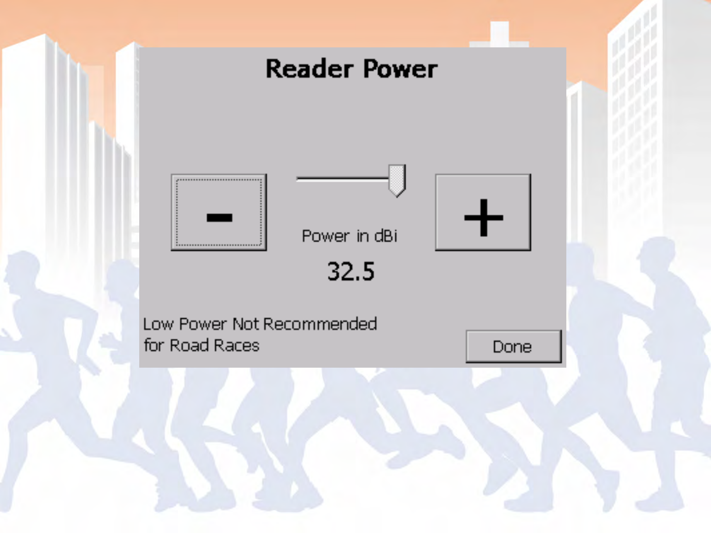
BoxScore – Reader Power
BoxScore – Messages


- Networking Controllers at Timing Points
- LAN Setup for PC and Controller
- WiFi Setup for PC and Controller
- Controller Setup for GPRS (Cellular) and
establishing a connection
- Basic Troubleshooting & Common Problems
- Open Q & A and setup help (if time allows)

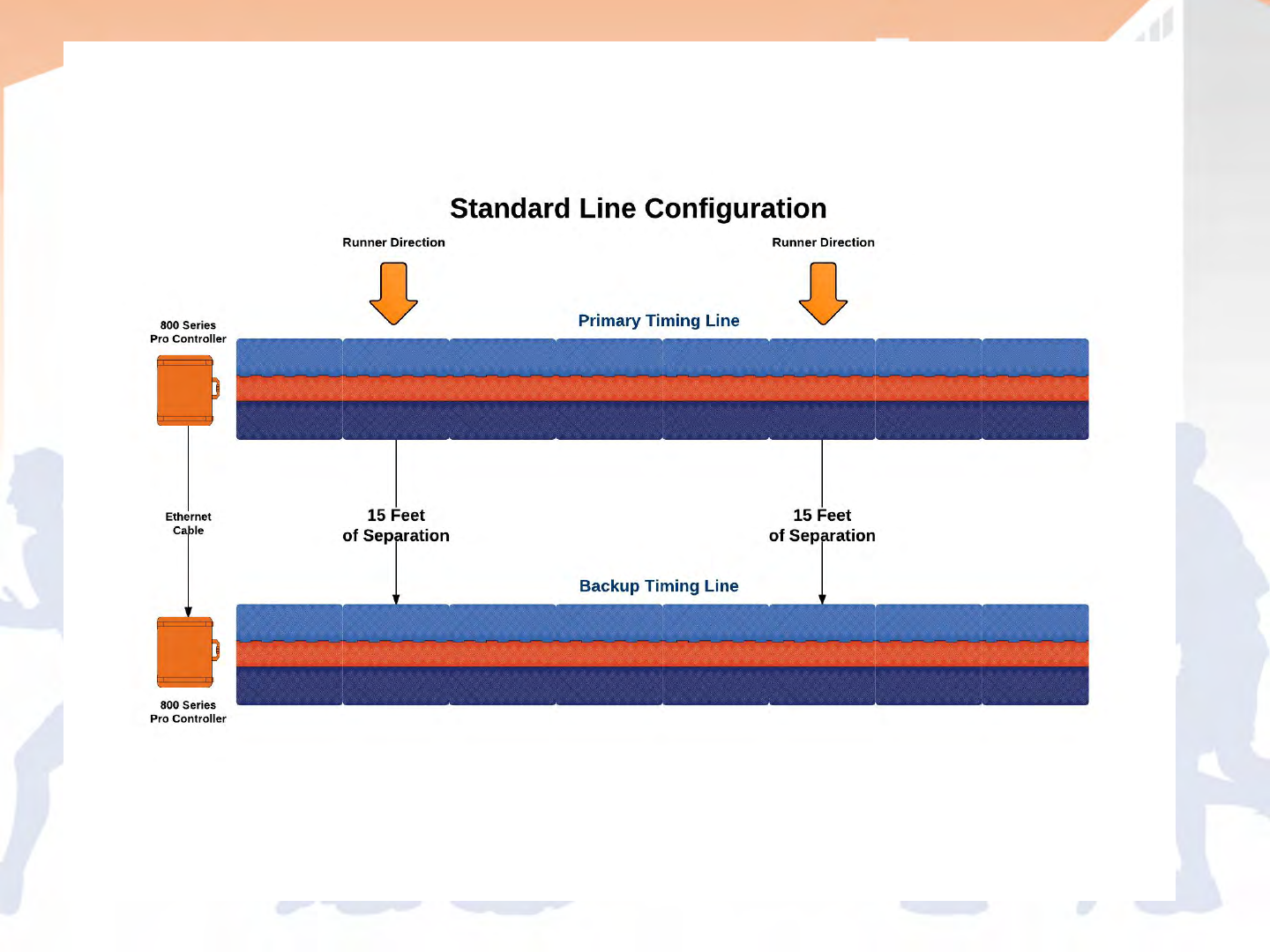
- Primary and backup controllers are
recommended to be connected with a
network cable
- All reads collected with each line are shared
creating data redundancy and allows you to
only collect the data from one controller as
needed
- If needed, you can also sort the data back out
later using virtual points or scoring software

- IP address is properly set as alternate
configuration for the ChronoTrack network:
172.20.23.(2-99) for Local Area Connection
- Firewalls disabled or set to allow connections
through CCSLite or port 61610
- Confirmed that no other anti-virus software
has an active firewall
- CCSLite is active
- Cable is connected

- Standard Network cable, no need for a
crossover cable
- Distance limitation vary based on cable
quality, average limitation approximately 300
ft.
Set to CT Network:
172.20.23.(2-99)
Configure > Network

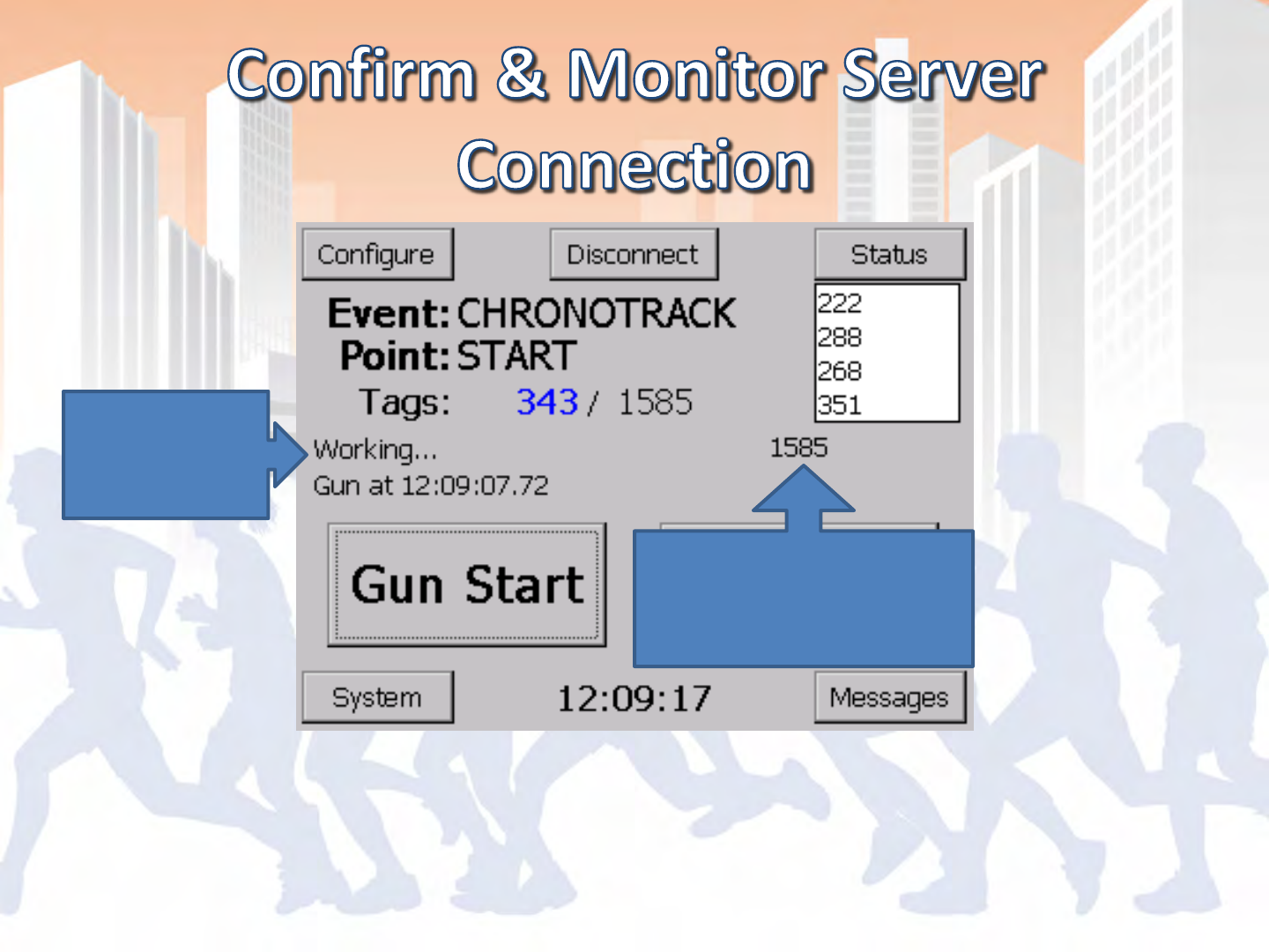
Main Screen of BoxScore
Hit Connect

Main Screen of BoxScore
Reports
Working…
Transferred Tag Count is
greater than or equal to
total tag reads

- IP address is properly set as alternate
configuration for the ChronoTrack network:
192.168.0.(2-99) for Wireless Area Connection
- Firewalls disabled or set to allow connections
through CCSLite or port 61610
- Confirmed that no other anti-virus software has
an active firewall
- CCSLite is active
- Ad Hoc Network is properly created and
connected to

Set to CT Network:
192.168.0.(2-99)
Configure > Network
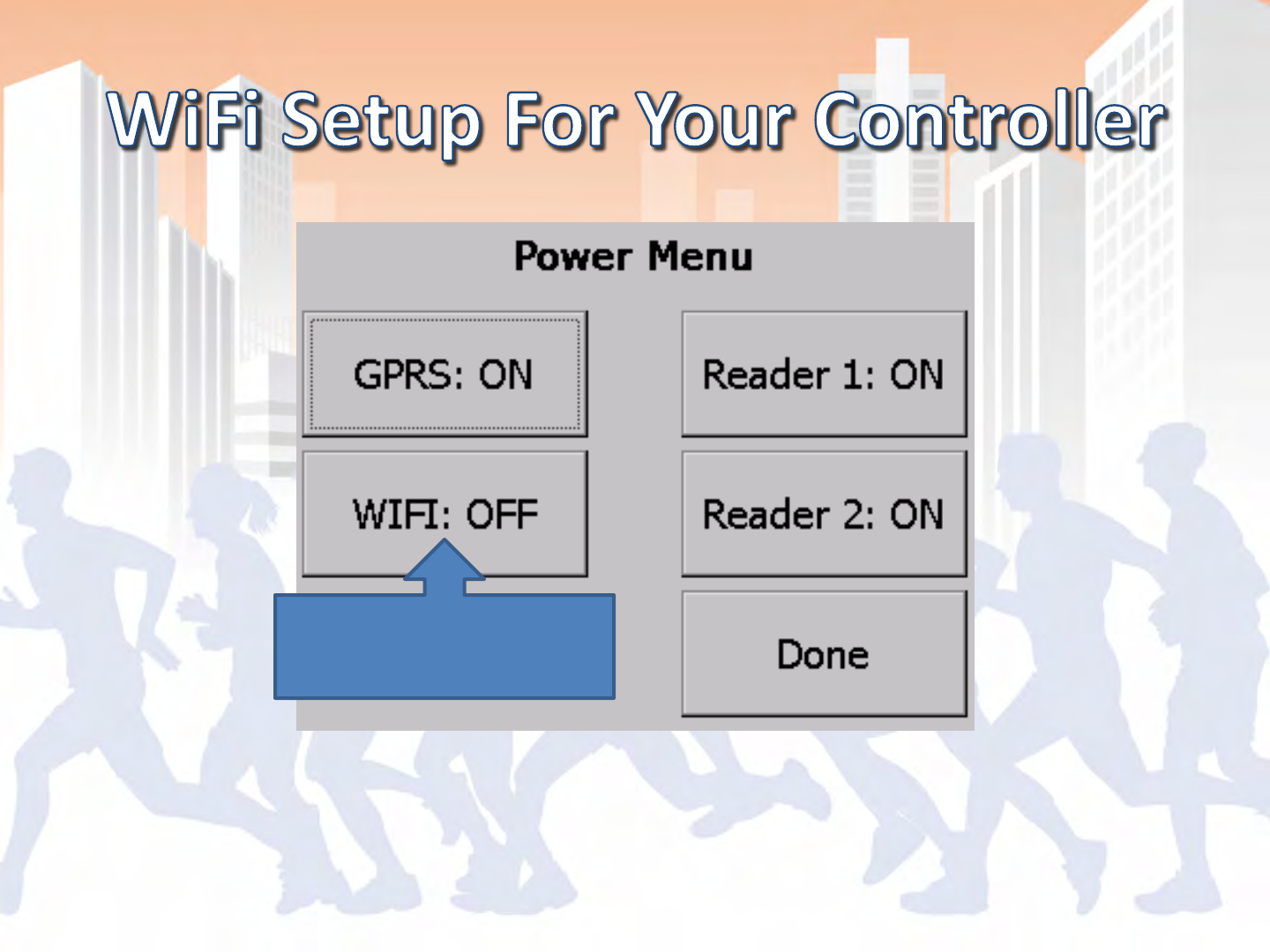
Configure > Power
WiFi must be powered
ON

Main Screen of BoxScore
Hit Connect
Main Screen of BoxScore
Reports
Working…
Transferred Tag Count is
greater than or equal to
total tag reads

- SIM Card with active data plan
- Scoring machine will also need an internet
connection
- May need high gain antennas if used in areas
with poor coverage
- Only need one connected controller per point
- Can connect multiple controllers at a point for
backup

- Confirm Server IP Setting
- Power GPRS Modem On
- Establish Cellular Data Connection
- Connect to the ChronoTrack Server

Set to CT Server:
72.13.13.238
Configure > Network
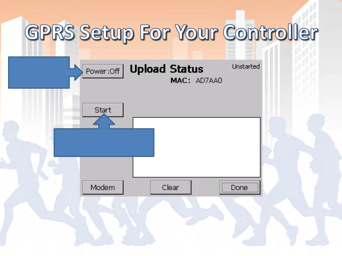
Status > Upload
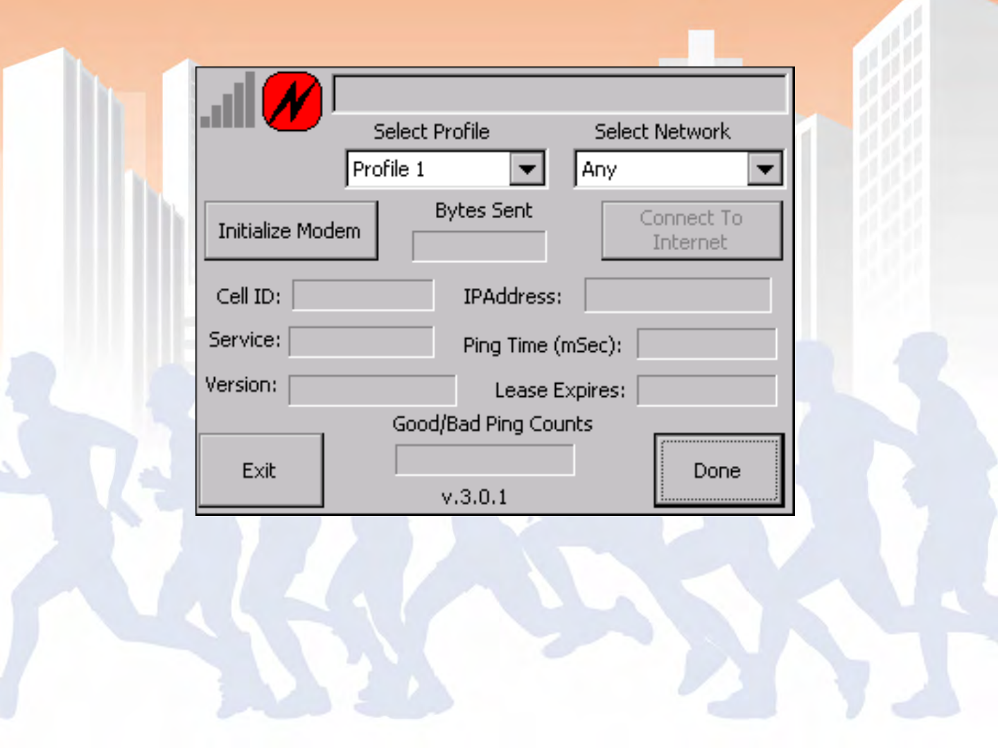
Power on if
modem is not
powered on
Then start the modem
software by hitting start
Status > Upload > Start(Modem)
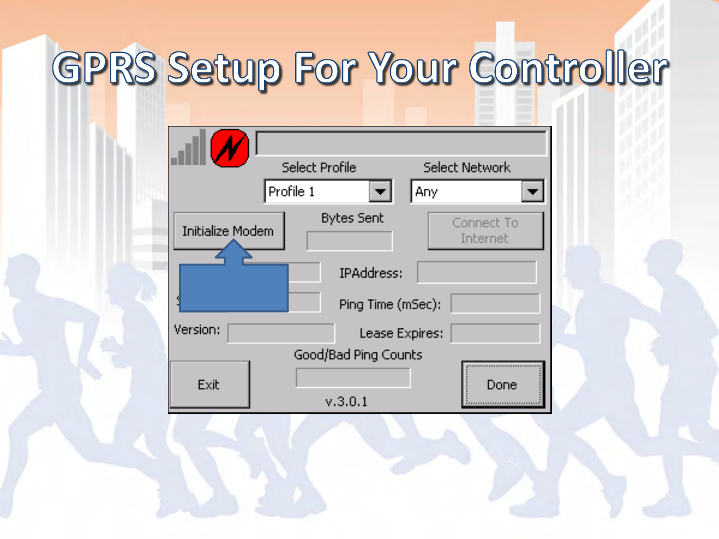
Initialize
Status > Upload > Start (Modem)
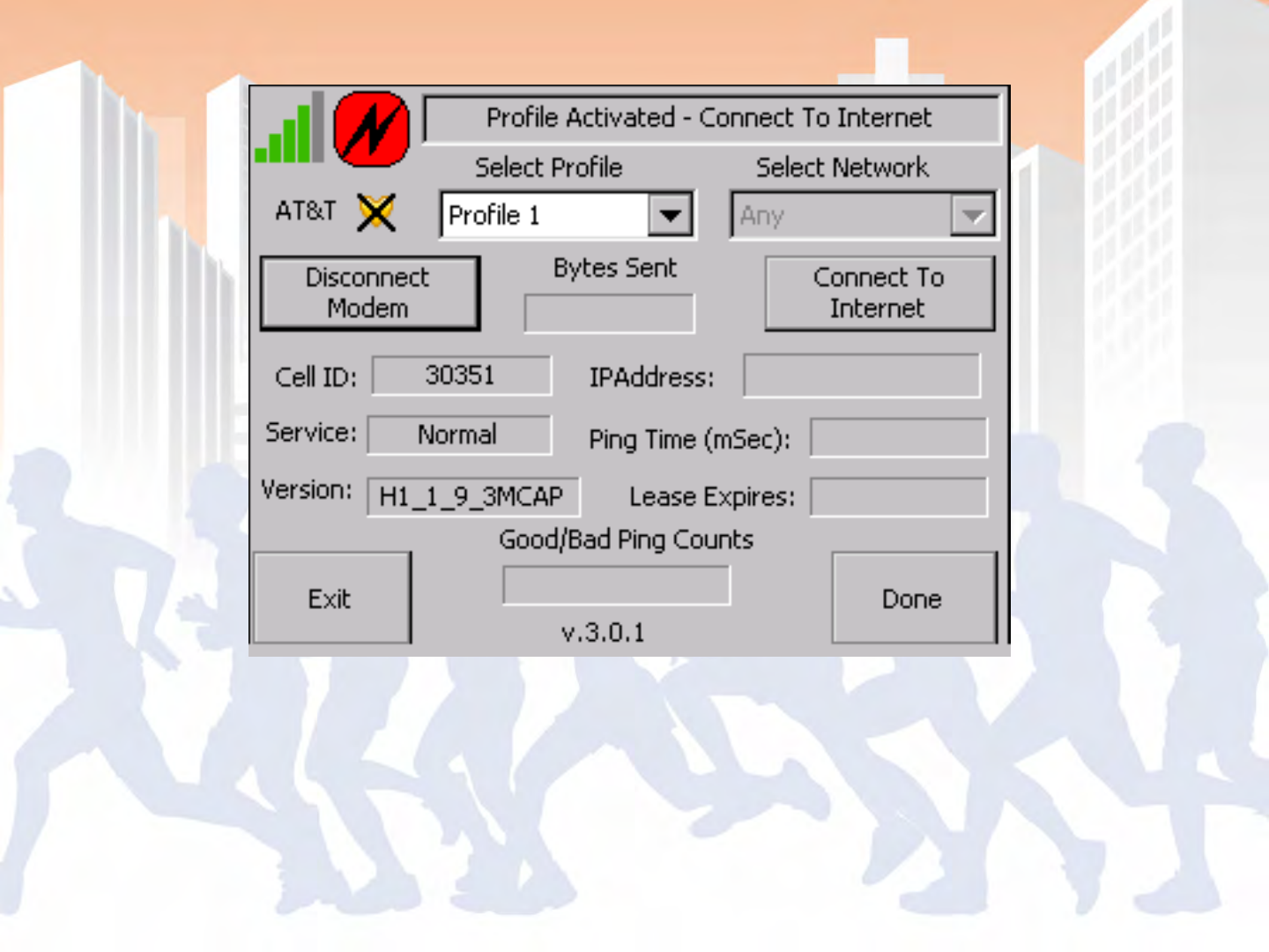
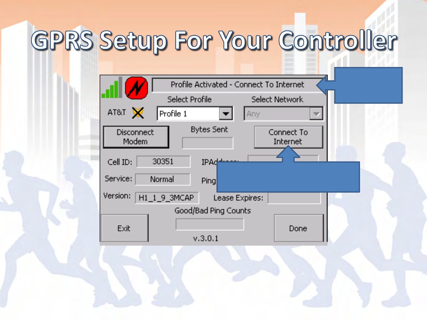
Wait for this
message
And follow it’s directions!
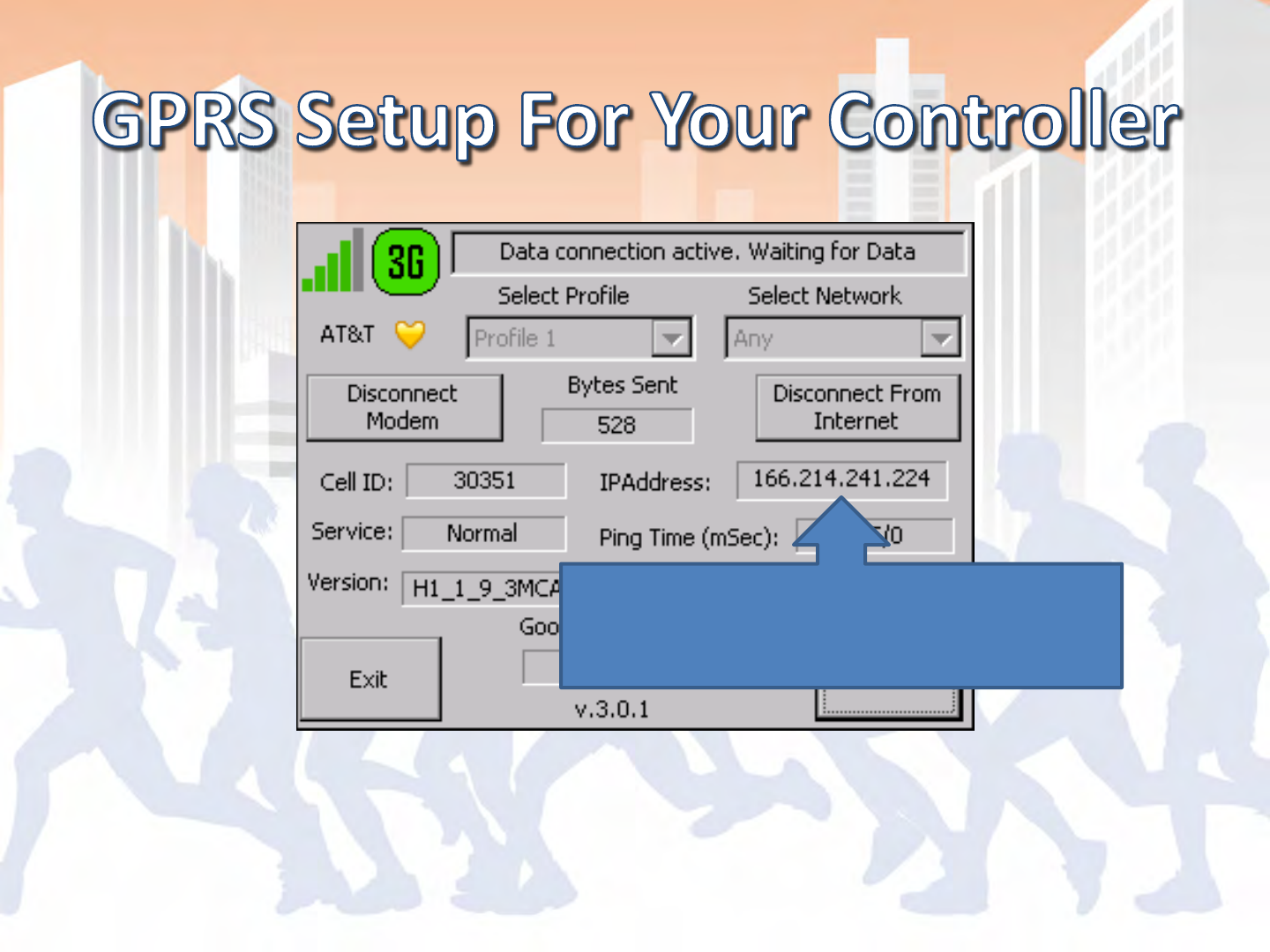
Status > Upload > Start (Modem)
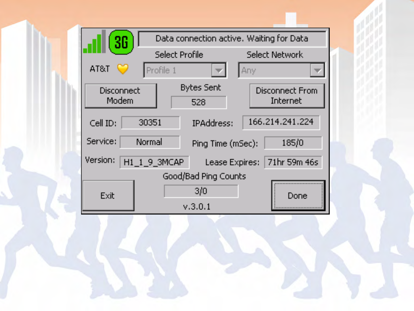
Once it acquires an IP address you can
proceed back to the main screen of
BoxScore
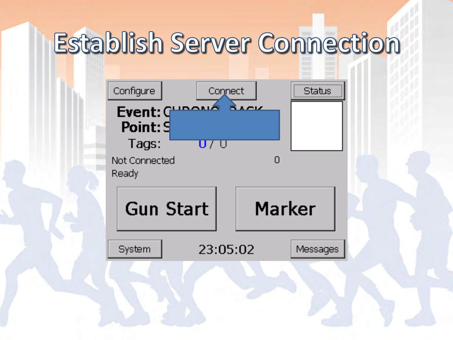
Main Screen of BoxScore
Hit Connect

Main Screen of BoxScore
Reports
Working…
Transferred Tag Count is
greater than or equal to
total tag reads

- Wrong Server Address set (possibly typos)
- 72.13.13.238 = ChronoTrack Cell Server
- 172.20.23.XX = LAN Connection
- 192.168.0.XX = WiFi Connection
- Component is not powered ON
- Faulty Hardware
- Broken Cable (clips commonly break)
- Inactive SIM card

- Confirm that the link lights are active on both
ends for LAN and WiFi
- Ping the appropriate IP address
- On your PC, pull up a command line and type in
“ping 172.20.23.100” (TPC LAN IP address) and
confirm a response