CipherLab 11661 Bluetooth Barcode Scanner User Manual
CipherLab Co., Ltd. Bluetooth Barcode Scanner
UserManual.wiki
>
CipherLab
>
11661 User Manual
User Manual
Navigation menu
Upload a User Manual
Namespaces
Wiki Guide
HTML
PDF
Info
Views
User Manual
Discussion / Help
Navigation
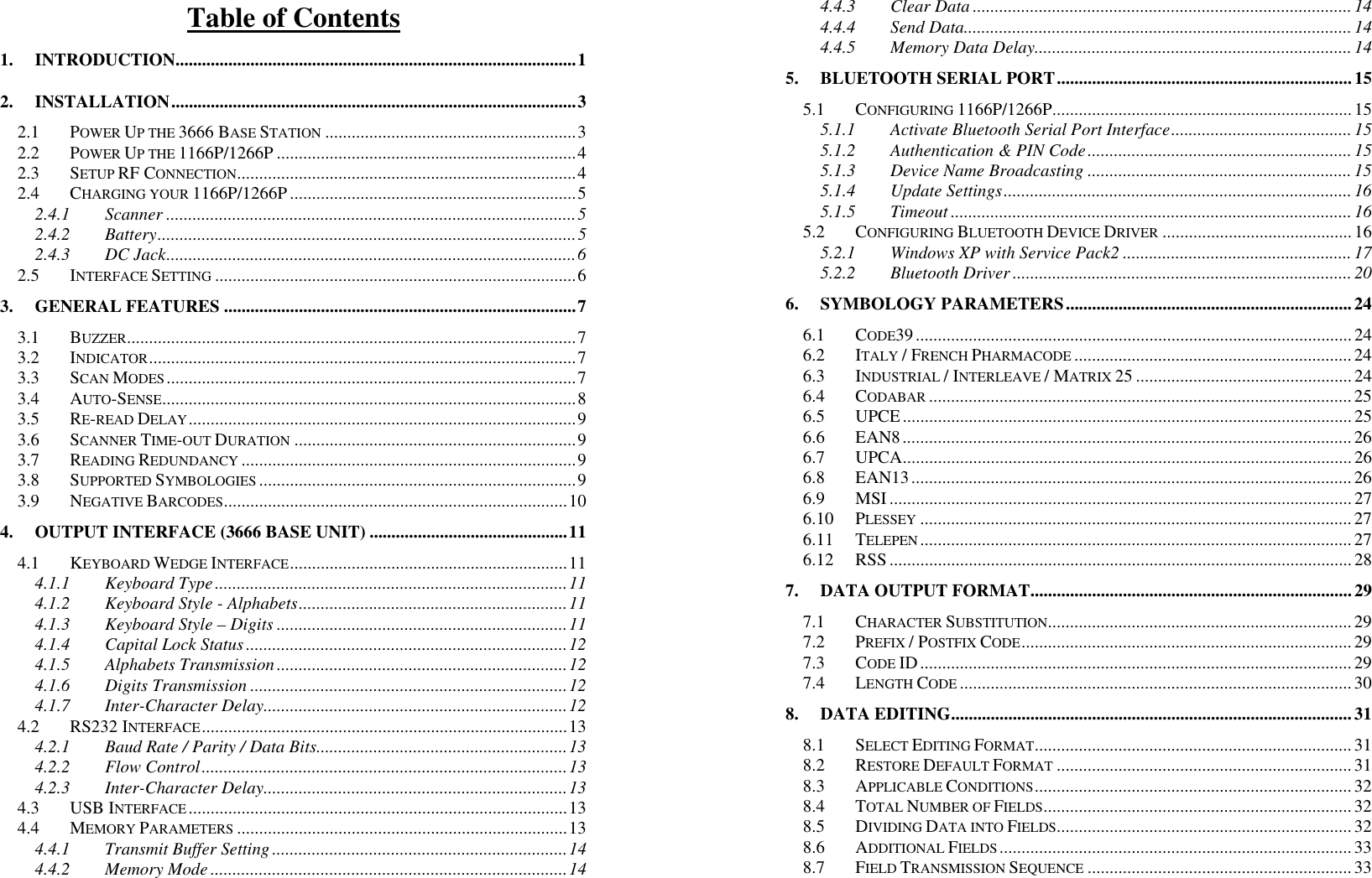
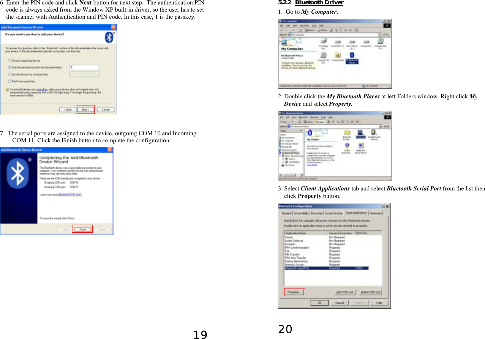
![276.9 MSI • Checksum Verification: Three kinds of checksum calculations can be implemented into MSI code: Single Modulo 10, Double Modulo 10, or Modulo 11 & 10 checksum. If the checksum character is incorrect, the barcode will not be read. • Checksum Transmission: User can control the checksum transmit ion format by configuring this parameter. 1) Transmitted 2) Last digit not transmitted 3) Last 2 digits not transmitted • Code Length Qualification: Because of the weak structure of the MSI code, a partial scan has a high probability of decoding as a valid but shorter MSI codes (known as short scan). To prevent this kind of undesired readings, the Code Length settings can help to ensure that the correct code is read by qualifying the allowable code length. Code length limitations can be set in 2 ways: Fixed Code Length and Max/Min code length. If the fixed code length is selected, up to 2 fixed lengths can be specified. And if max / min code length is selected, the max length and the min length must be specified, and the scanner will only accept those codes with lengths fall between max / min length specified. 6.10 Plessey • Convert to UK Plessey: If this parameter is enabled, the scanner will change each occurrence of the character ‘A’ into character ‘X’ in the code. • Checksum Transmission: If this parameter is enabled, the checksum characters (two characters) will be transmitted together with data. 6.11 Telepen • Telepen Output: There are two flavors of encoding formats for Telepen. One is the original Telepen format and another is AIM Telepen format. User can choose the desired encoding format for Telepen readings. 286.12 RSS • Code ID Selection: User has choice of using RSS Code ID (‘]e0’) or EAN128 Code ID (‘]C1’). • Code ID Transmission: If this parameter is enabled, the Code ID selected by the preceding setting will be included in the data being transmitted. • Application ID Transmission: If this parameter is enabled, the Application ID will be included in the data being transmitted. • Checksum Transmission: If this parameter is enabled, the checksum character will be transmitted together with data.](https://usermanual.wiki/CipherLab/11661/User-Guide-620602-Page-17.png)
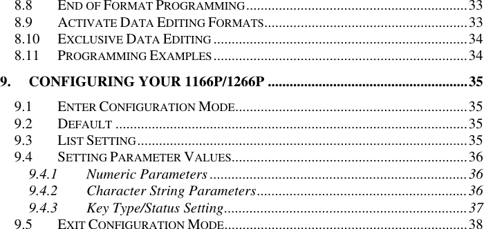
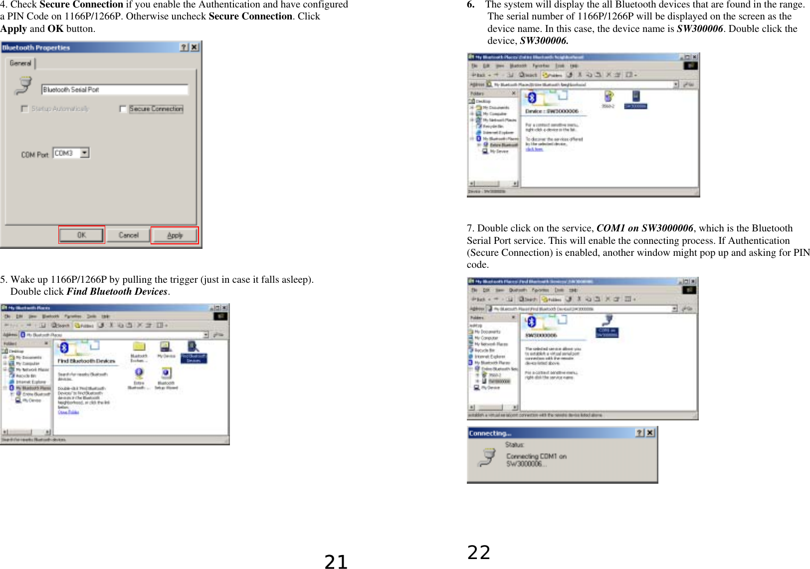
![297. Data Output Format Data read by the scanner will be processed in the following sequence (RS-232, Keyboard Wedge and USB interfaces). 1) The character substitution is performed on the barcode data. 2) The Code ID and the Length Code are inserted at the beginning of the data as shown below. [Code ID] [Length Code] [Data] 3) The resulting data of step 1 will be processed by the editing formats. For details, please refer to the section “Data Editing”. 4) And finally the Prefix Code and the Postfix Code will be added before transmission. [Prefix Code] [Resulting Data of Step 3] [Postfix Code] 7.1 Character Substitution There are three character substitution settings on the scanner. These settings are configured on a character base. That is, a specific character is to be substituted by another character. The character substitution is performed on every occurrence of the characters specified in these settings. Be aware, the substitution is performed only on the barcode itself (exclude Prefix Code, Postfix Code, Code ID, Length Code or any Additional Field) and is performed before editing mode processing. If only the character to be replaced is specified, every occurrence of that character in the barcode will be taken away. 7.2 Prefix / Postfix Code Up to four characters of prefix / postfix code can be configured for the scanner. 7.3 Code ID Up to two characters of Code ID can be configured for each symbology. To minimize the Code ID configuration efforts, the scanner provides five predefined Code ID Sets that user can select from. User can first select one of the Code ID Sets and then make desired modifications. The pre-defined Code ID Sets are shown below. 30 Set 1 Set 2 Set 3 Set 4 Set 5Code 39 A C Y M AItaly Pharmacode A C Y M AFrench Pharmacode A C Y M AIndustrial 25 C H H H S Interleave 25 D I Z I S Matrix 25 E G G G S Codabar F N X N F Code 93 I L L L GCode 128 H K K K C UPCE S E C E E EAN8 P B B FF E EAN13 M A A F E MSI VVDP MPlessey W W E Q P UPCA J A A A E Telepen Z 7.4 Length Code Two digits Length Code representing the length of data (character count) can be inserted in front of data being transmitted. This Length Code parameter can be individually enabled or disabled for each barcode symbology.](https://usermanual.wiki/CipherLab/11661/User-Guide-620602-Page-18.png)