CipherLab 1564 BT Barcode Scanner User Manual 1564 Barcode Scanner
CipherLab Co., Ltd. BT Barcode Scanner 1564 Barcode Scanner
UserManual.wiki
>
CipherLab
>
1564 User Manual
manual
Navigation menu
Upload a User Manual
Namespaces
Wiki Guide
HTML
PDF
Info
Views
User Manual
Discussion / Help
Navigation


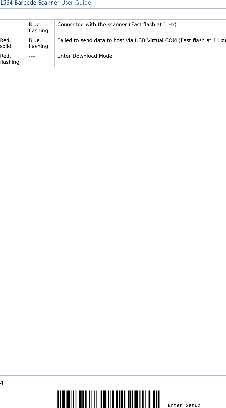
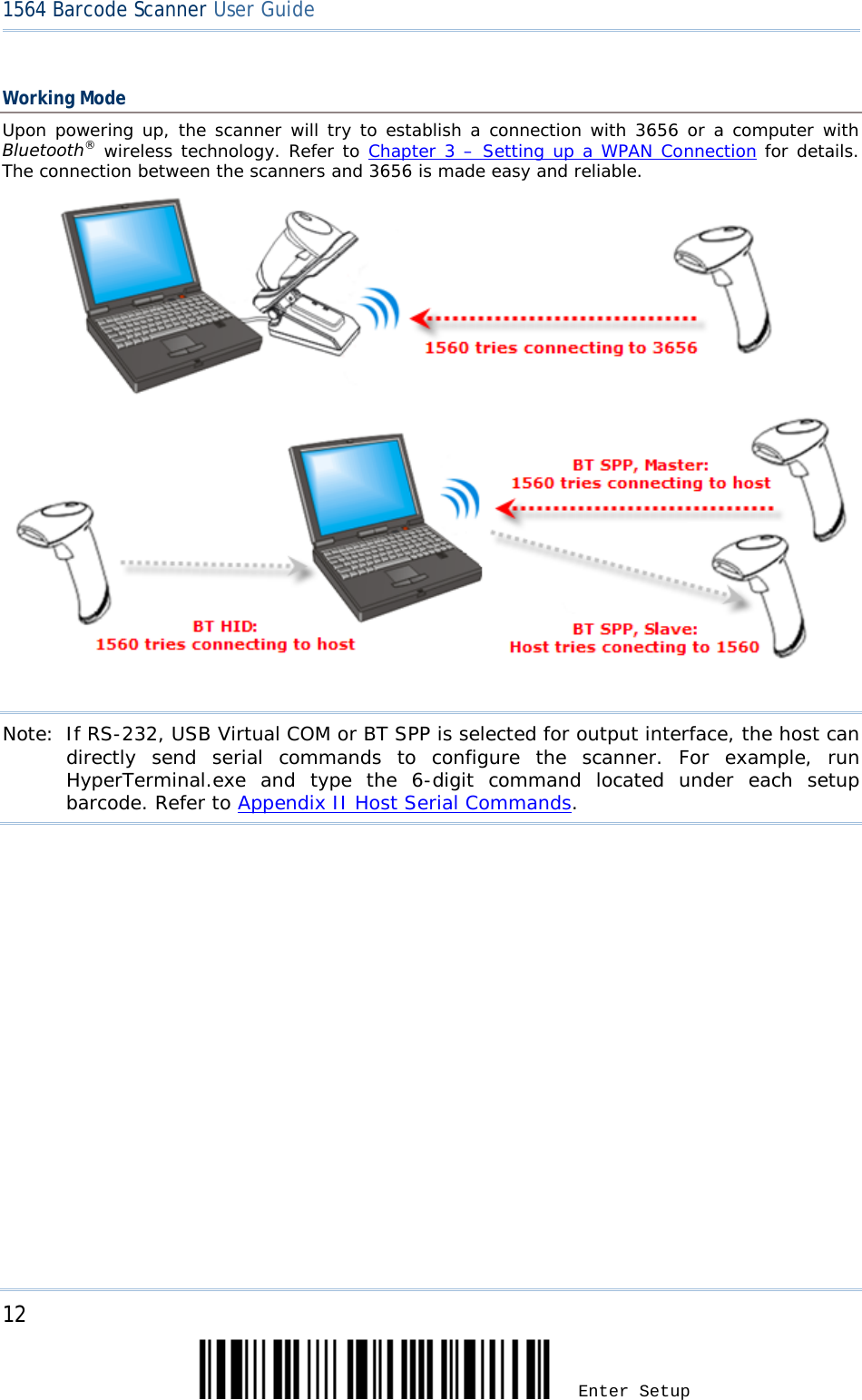
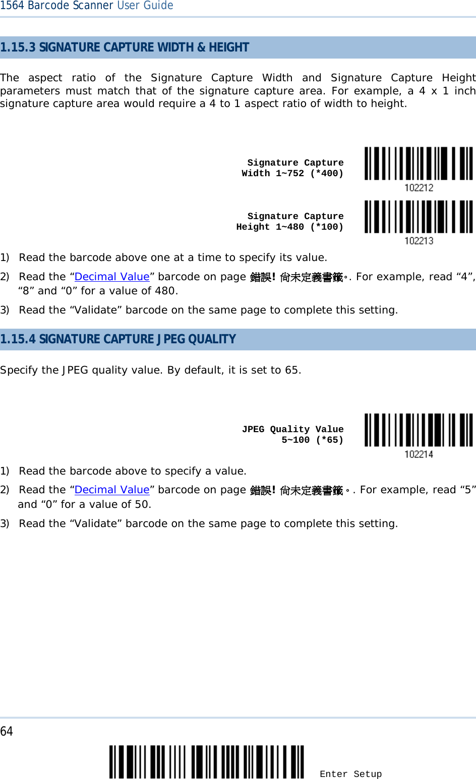
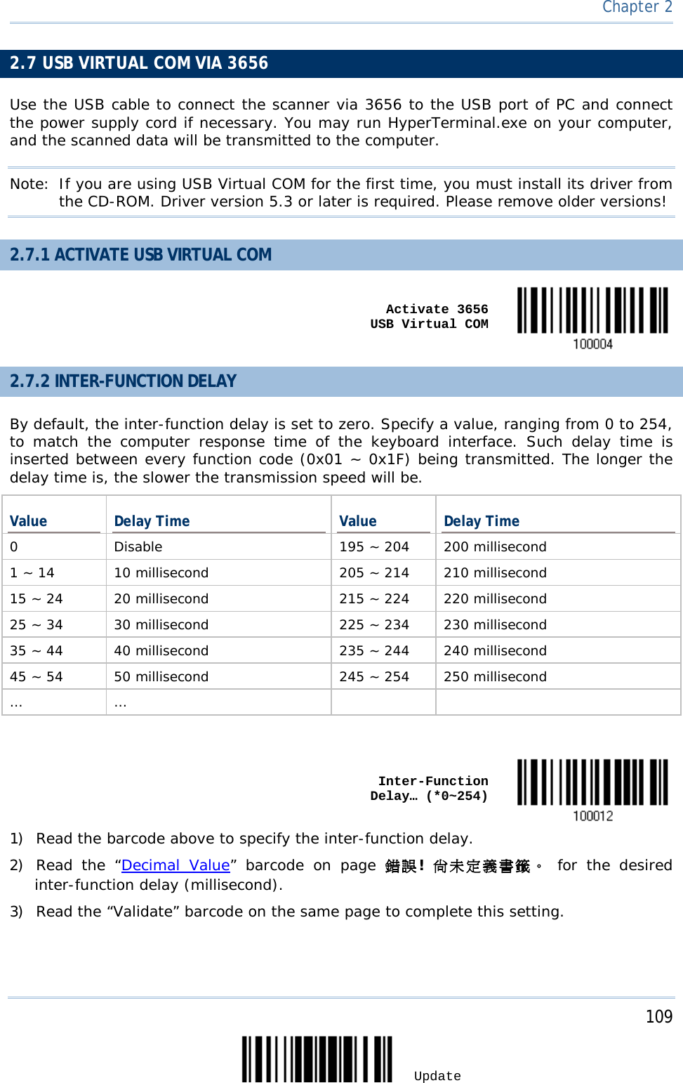
![3 Update SETTING UP 3656 Capable of charging 1564, the 3656 stand is specifically designed for the scanner to communicate with a host computer wirelessly. The connection between the scanners and 3656 is made easy and reliable. Refer to 3.1.1 Connect to 3656. Two LED indicators are provided for power and communications status. Power LED Meaning Red, solid --- Power ON --- --- Power OFF Communication LED Meaning --- Blue, solid Initialize Red, solid --- Failed to establish a USB connection Red, solid Blue, flashing Serial command mode with USB Virtual COM or RS-232: wait 3 seconds for starting a serial command Red, flashing Blue, flashing Serial command mode with USB HID: wait 3 seconds for pressing [Num Lock] or [Caps Lock] 5 times via keyboard --- Blue, flashing Wait for connection request from the scanner (Slow flash at 0.5 Hz)](https://usermanual.wiki/CipherLab/1564/User-Guide-1397877-Page-13.png)
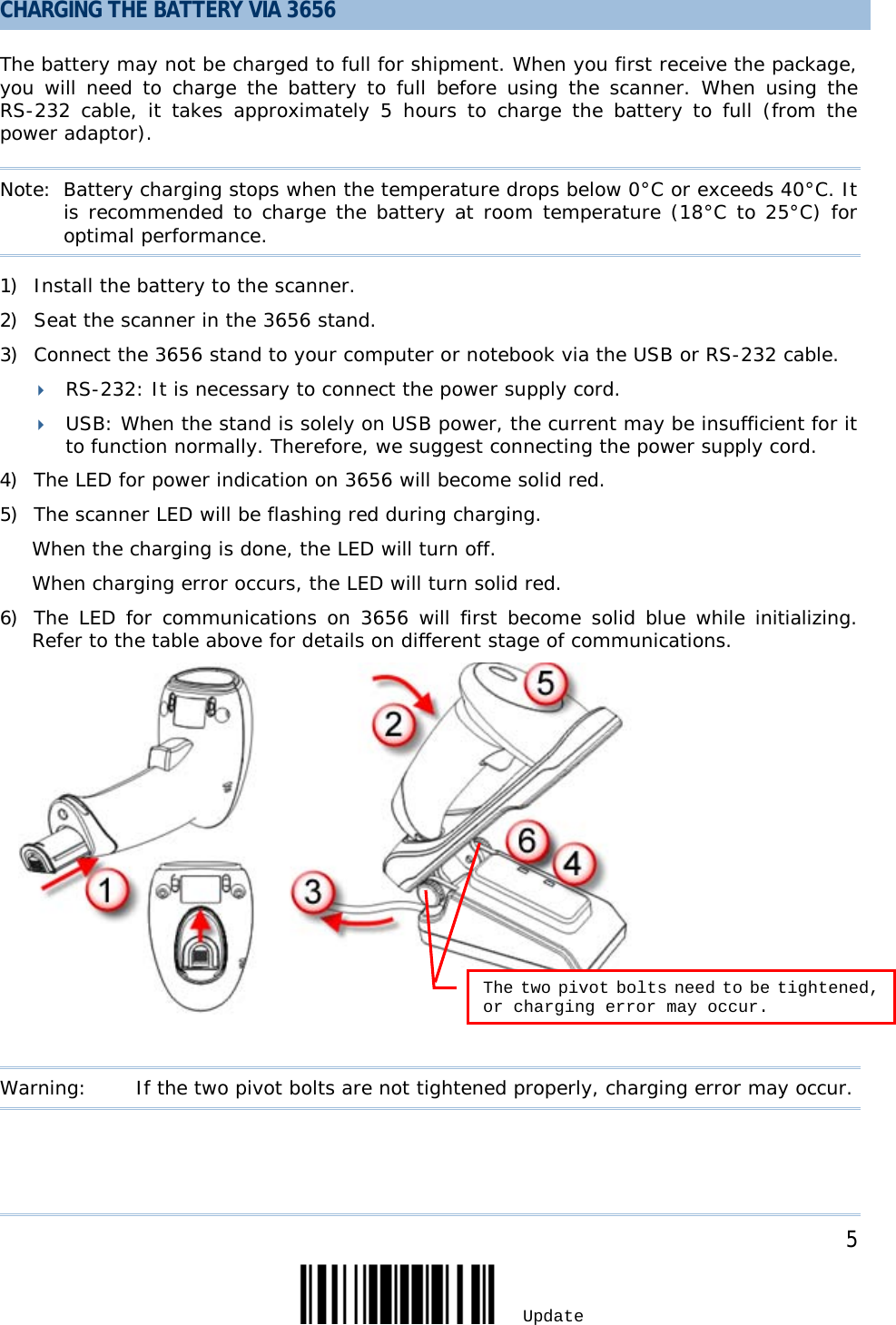
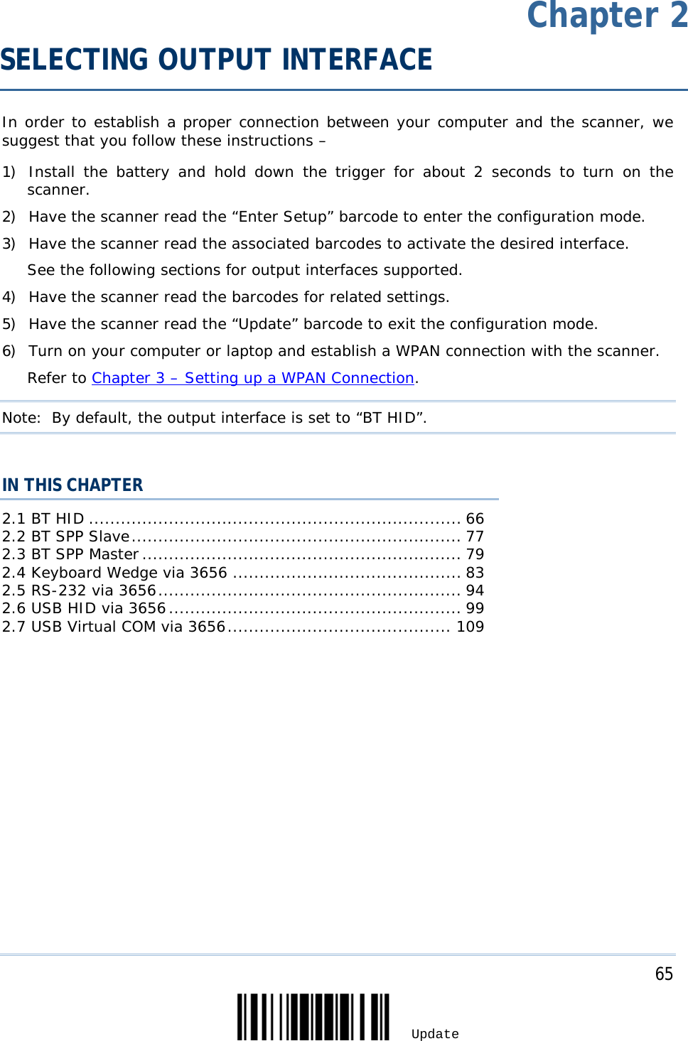
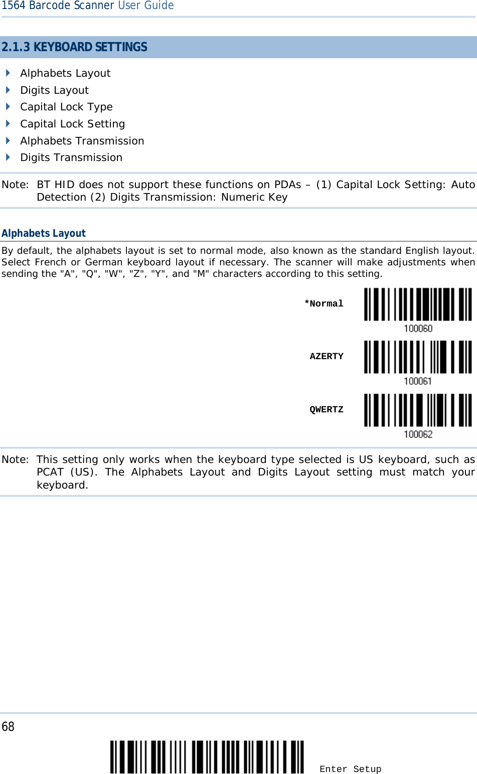
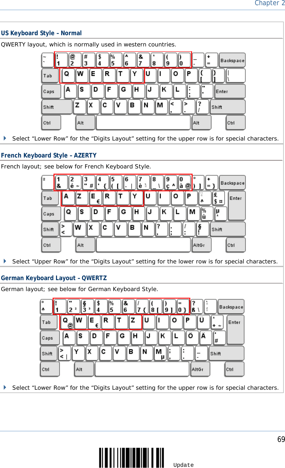
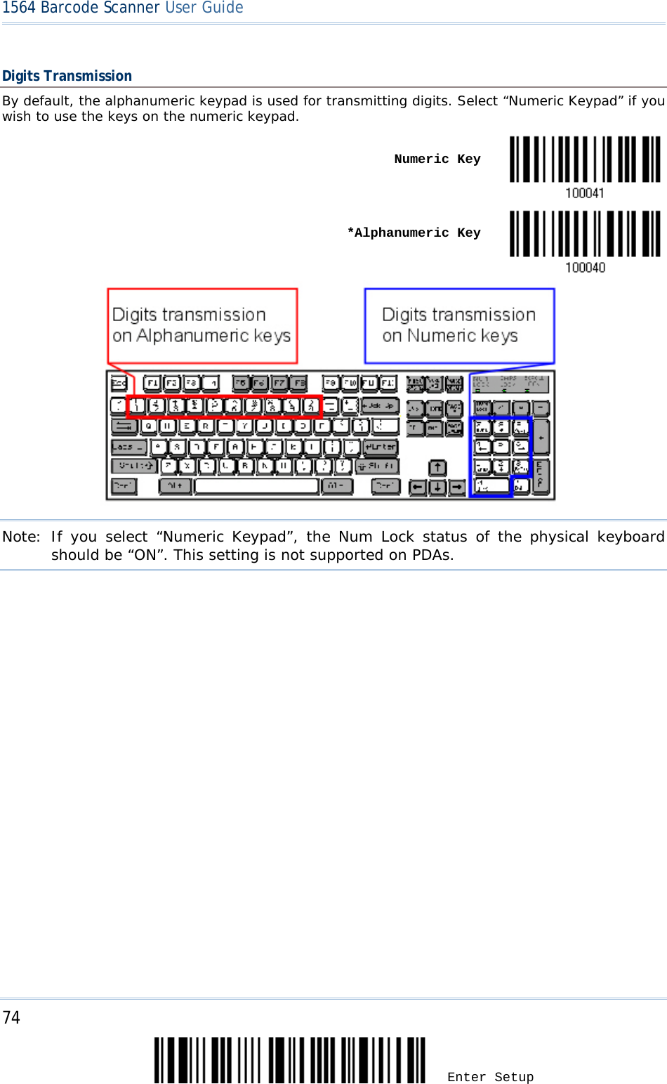
![70 Enter Setup 1564 Barcode Scanner User Guide Digits Layout Select a proper layout that matches the alphabets layout. The scanner will make adjustments according to this setting. Options Description Normal Depends on the [Shift] key or [Shift Lock] setting Lower Row For QWERTY or QWERTZ keyboard Upper Row For AZERTY keyboard *Normal Upper Row Lower Row Note: This setting is to be used with the Character Substitution setting when support to certain keyboard types (languages) is unavailable but required.](https://usermanual.wiki/CipherLab/1564/User-Guide-1397877-Page-80.png)
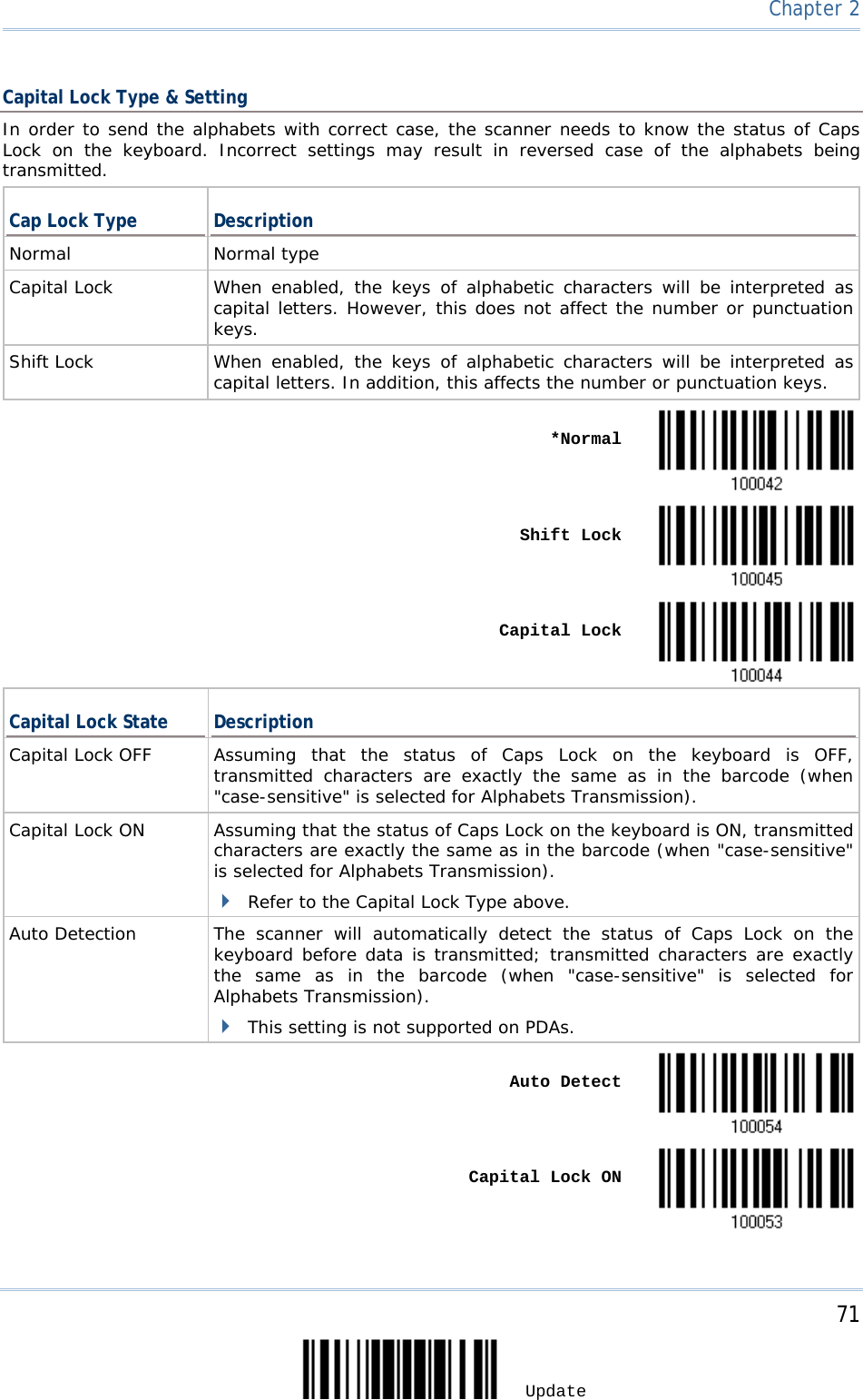
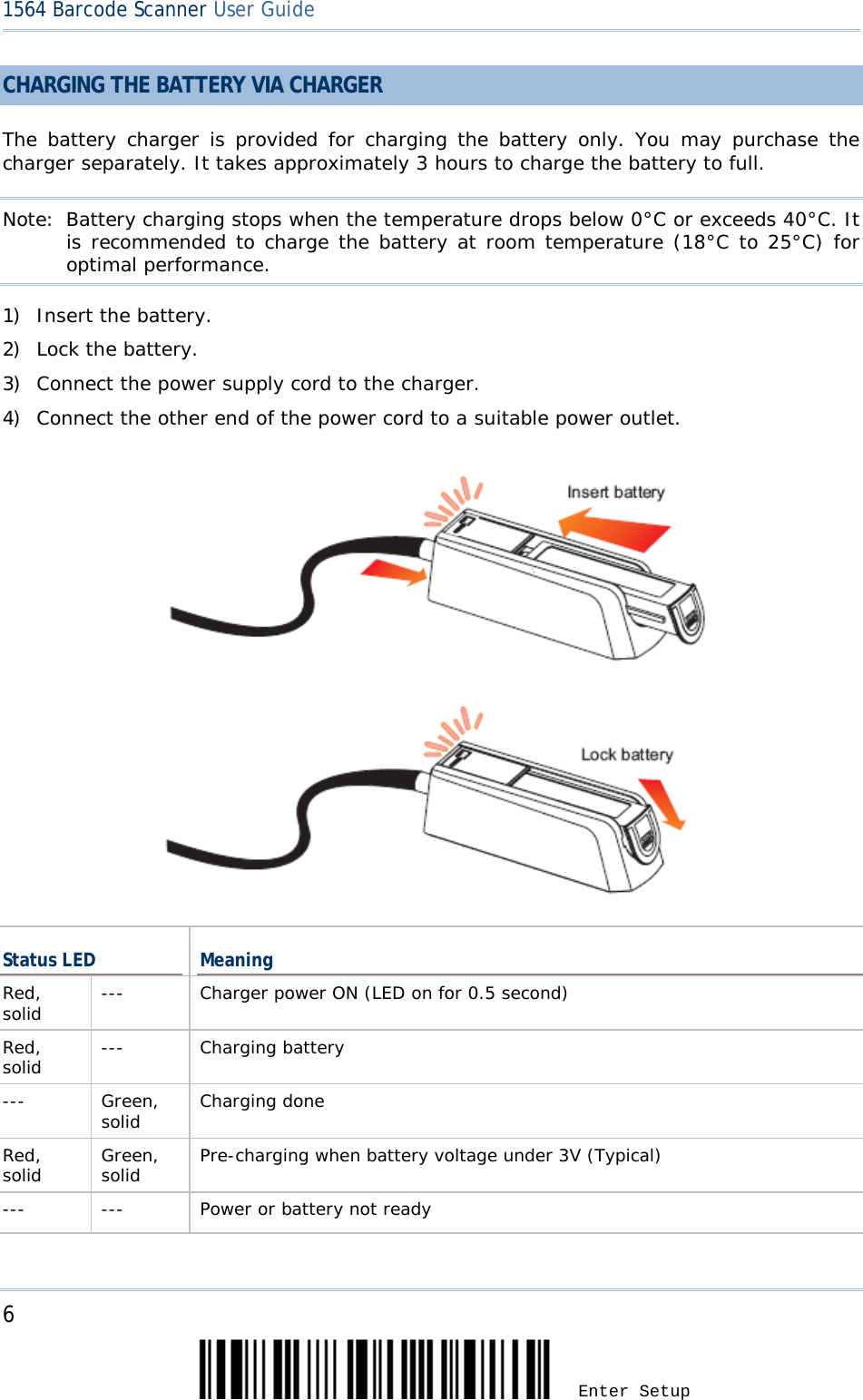
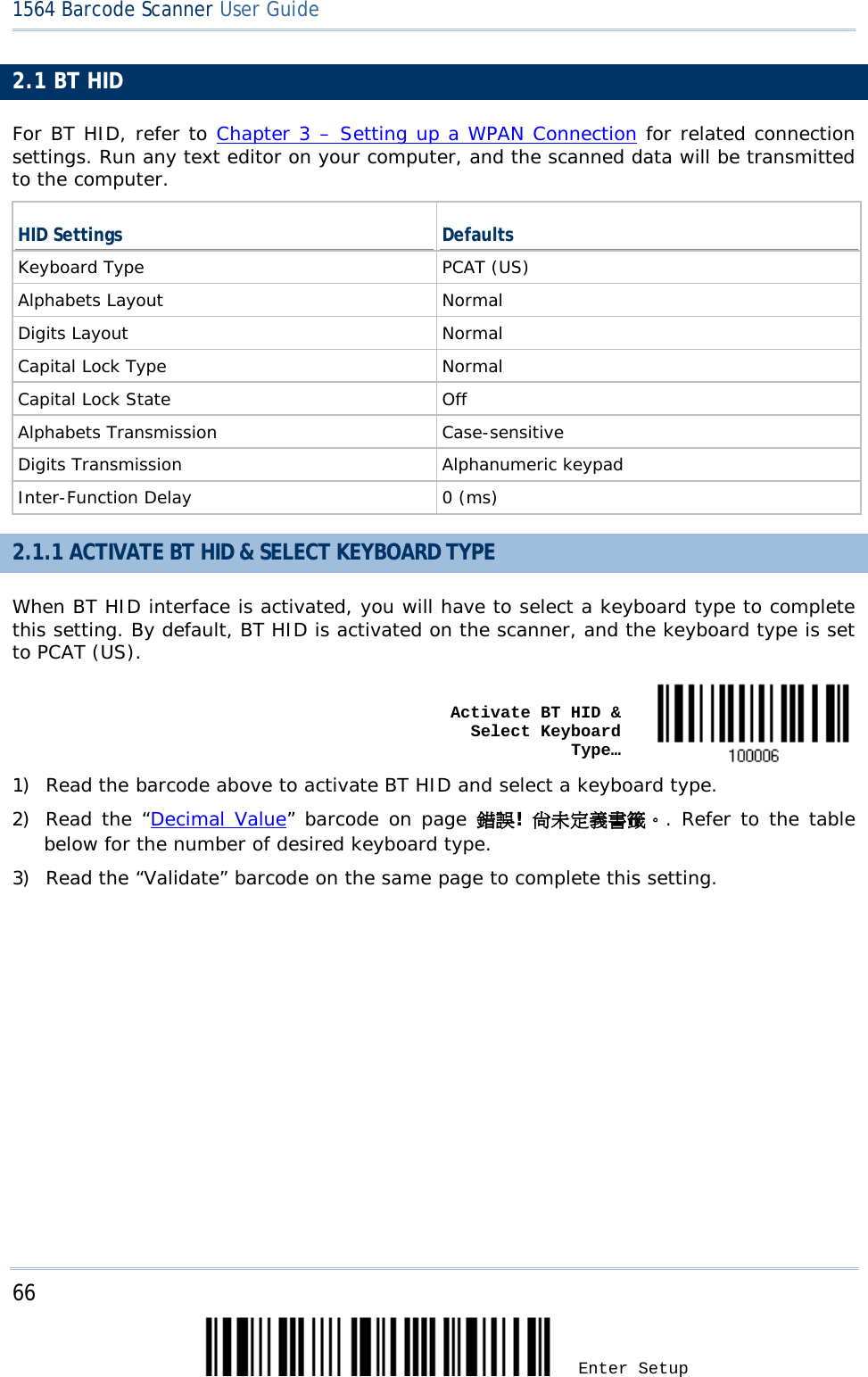
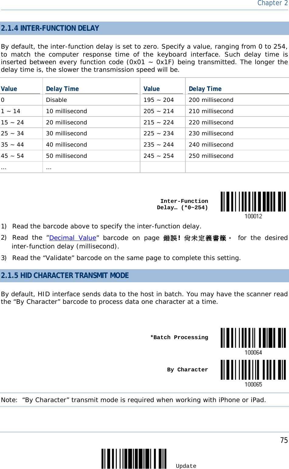
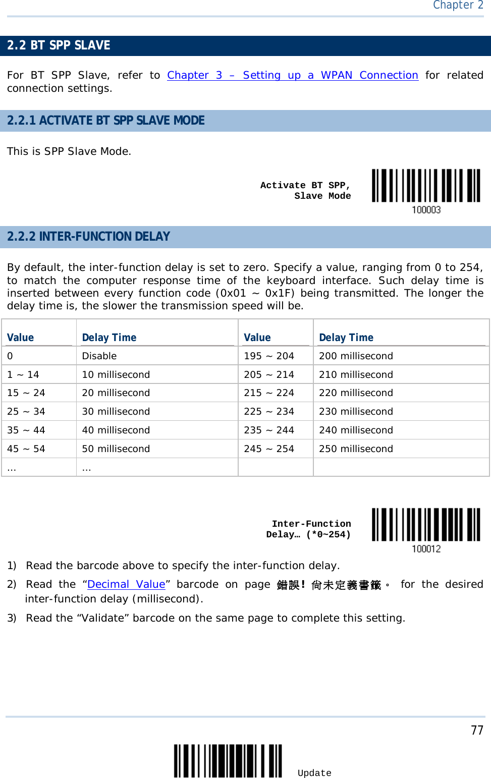
![73 Update Chapter 2 Alphabets Transmission By default, the alphabets transmission is case-sensitive, meaning that the alphabets will be transmitted according to their original case, the status of Caps Lock on the keyboard, as well as the Capital Lock setting. Select [Ignore Case] to have alphabets transmitted according to the status of Caps Lock on the keyboard only. Ignore Case *Case-sensitive Refer to 5.1 Letter Case.](https://usermanual.wiki/CipherLab/1564/User-Guide-1397877-Page-83.png)
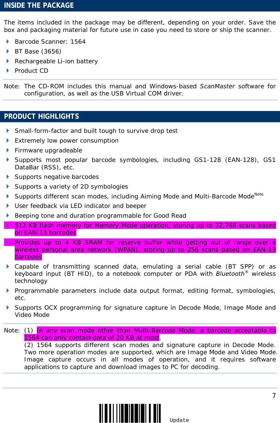
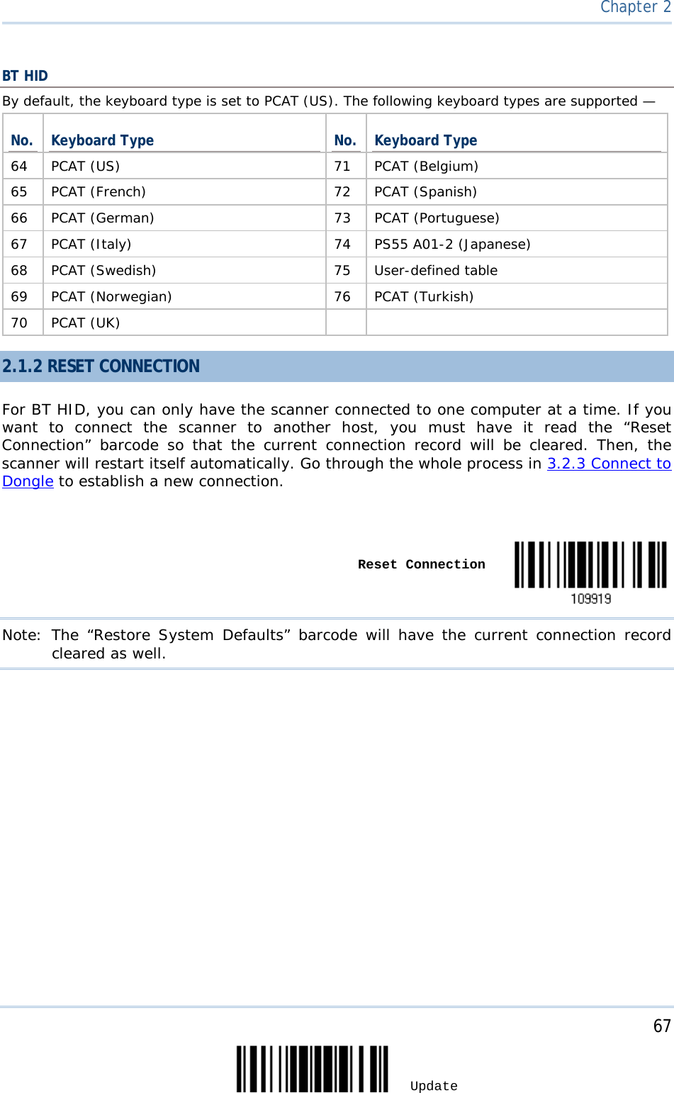
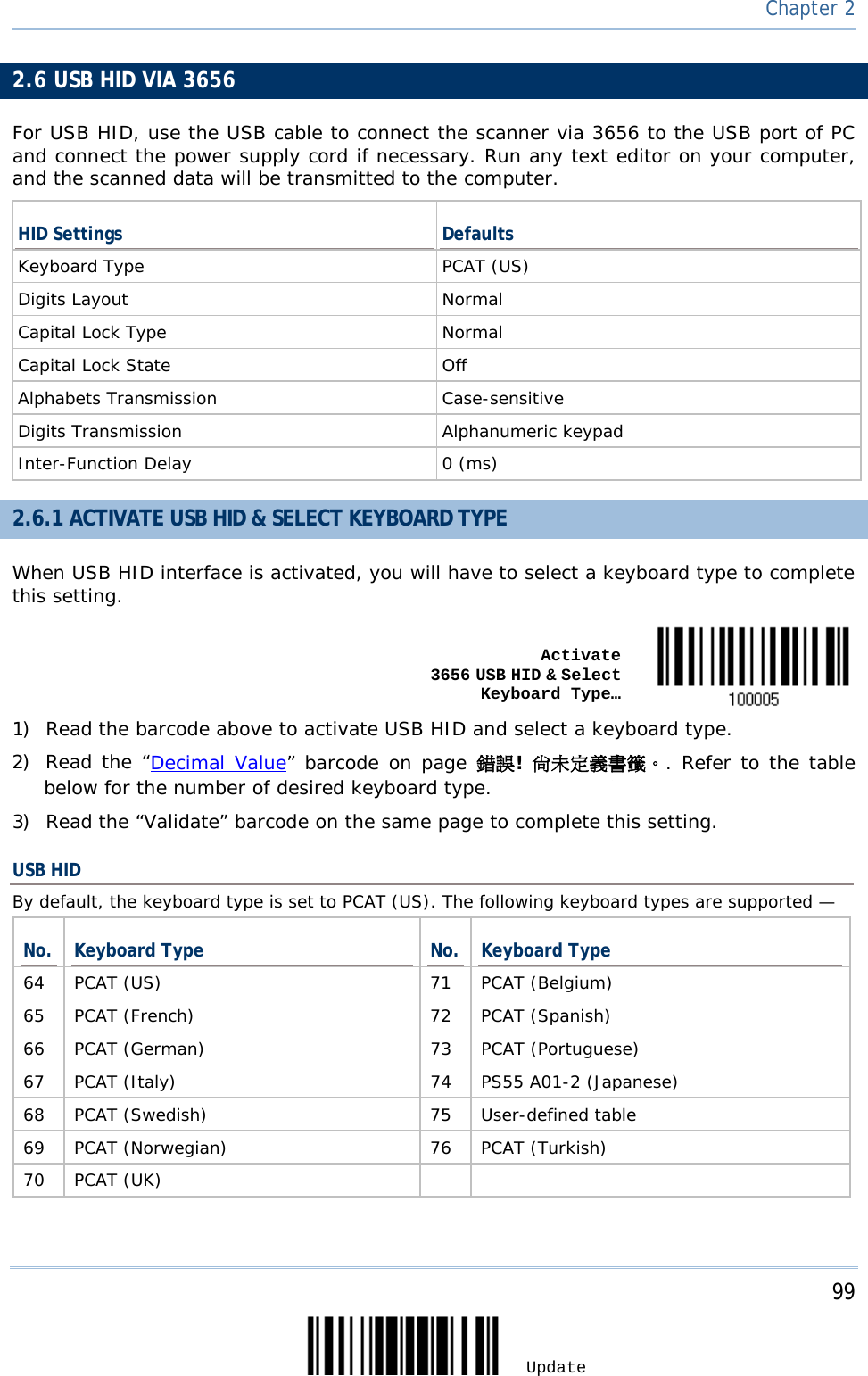
![76 Enter Setup 1564 Barcode Scanner User Guide 2.1.6 KEYPAD SUPPORT FOR IPHONE/IPAD When the scanner has been successfully connected to iPhone or iPad for data collection, the onscreen keypad of iPhone or iPad will disappear. You may have the scanner read the “Use POWER Key to Show or Hide Keypad” barcode in advance. Then, it will allow pressing the [Power/Delete] key to show or hide the onscreen keypad. Note: This function only works for (1) iPhone 4 and 3GS version 4.1 or later, and (2) iPad version 4.2 or later. *Normal Use POWER Key to Show or Hide Keypad Instead of using the [Power/Delete] key, you may have the scanner read the following barcode to show or hide the keypad. Show or Hide Keypad When connecting the scanner to iPhone or iPad, have the scanner read the following barcode to show or hide the keypad if necessary. Show or Hide Keypad](https://usermanual.wiki/CipherLab/1564/User-Guide-1397877-Page-86.png)

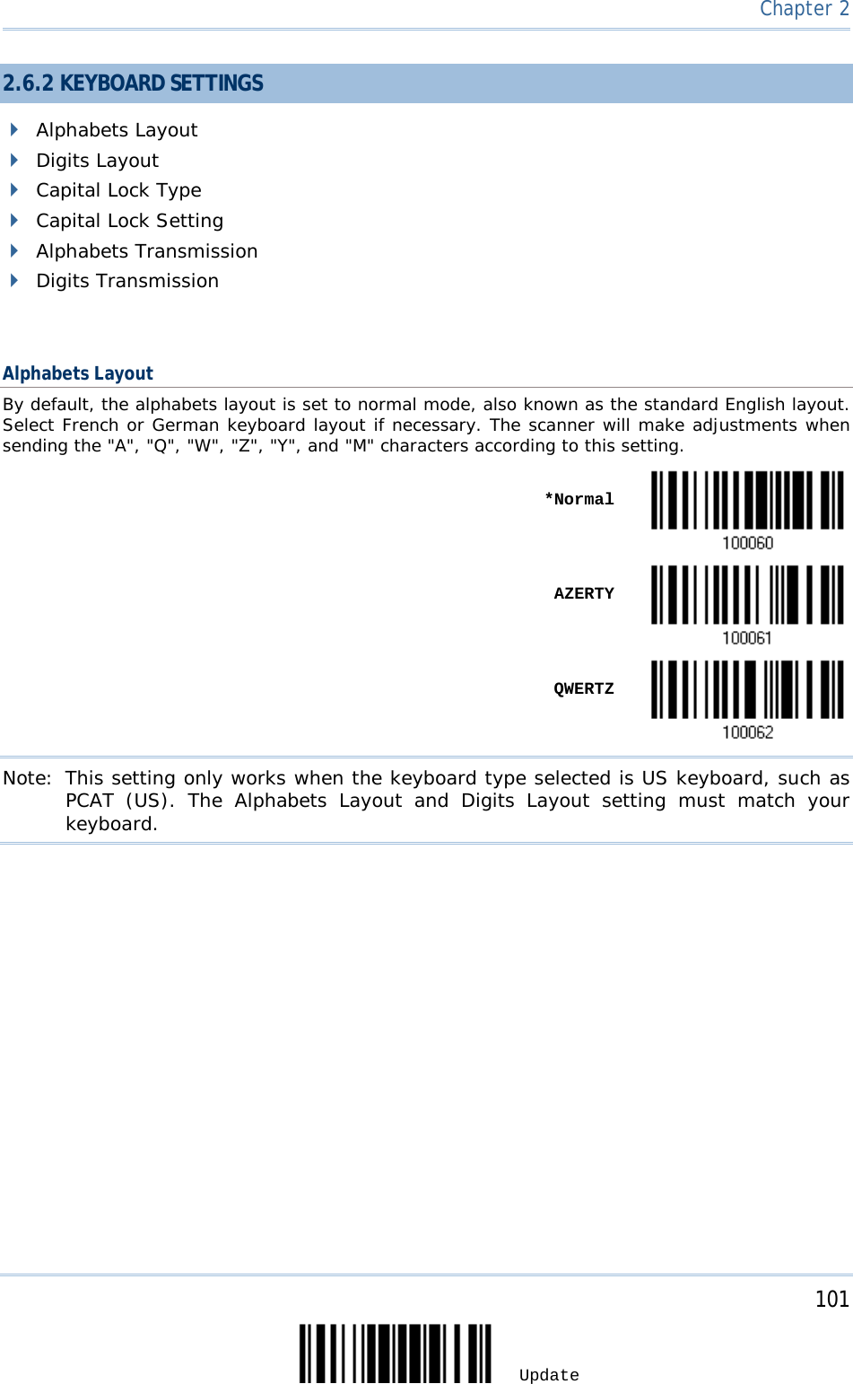
![87 Update Chapter 2 Digits Layout Select a proper layout that matches the alphabets layout. The scanner will make adjustments according to this setting. Options Description Normal Depends on the [Shift] key or [Shift Lock] setting Lower Row For QWERTY or QWERTZ keyboard Upper Row For AZERTY keyboard *Normal Upper Row Lower Row Note: This setting is meant to be used with the Alphabets Layout; and perhaps with the Character Substitution setting when support to certain keyboard types (languages) is unavailable but required.](https://usermanual.wiki/CipherLab/1564/User-Guide-1397877-Page-97.png)


![90 Enter Setup 1564 Barcode Scanner User Guide Alphabets Transmission By default, the alphabets transmission is case-sensitive, meaning that the alphabets will be transmitted according to their original case, the status of Caps Lock on the keyboard, as well as the Capital Lock setting. Select [Ignore Case] to have alphabets transmitted according to the status of Caps Lock on the keyboard only. Ignore Case *Case-sensitive Refer to 5.1 Letter Case.](https://usermanual.wiki/CipherLab/1564/User-Guide-1397877-Page-100.png)
![92 Enter Setup 1564 Barcode Scanner User Guide ALT Composing By default, Alternate key composing is disabled. Select [Yes] to allow emulating Alternate key code of a specific keyboard character. For example, [Alt] + [065] will be sent to host for the character “A” regardless the keyboard type you are using. Yes *No Laptop Support By default, laptop support is disabled. It is suggested to enable this feature if you connect the wedge cable to a laptop without an external keyboard being inter-connected. Enable *Disable](https://usermanual.wiki/CipherLab/1564/User-Guide-1397877-Page-102.png)


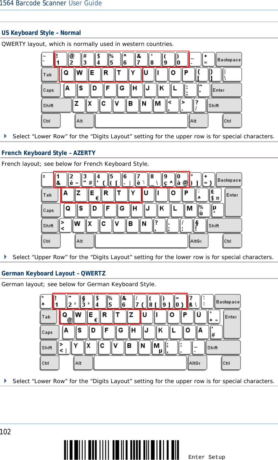
![103 Update Chapter 2 Digits Layout Select a proper layout that matches the alphabets layout. The scanner will make adjustments according to this setting. Options Description Normal Depends on the [Shift] key or [Shift Lock] setting Lower Row For QWERTY or QWERTZ keyboard Upper Row For AZERTY keyboard *Normal Upper Row Lower Row Note: This setting is to be used with the Character Substitution setting when support to certain keyboard types (languages) is unavailable but required.](https://usermanual.wiki/CipherLab/1564/User-Guide-1397877-Page-113.png)
![106 Enter Setup 1564 Barcode Scanner User Guide Alphabets Transmission By default, the alphabets transmission is case-sensitive, meaning that the alphabets will be transmitted according to their original case, the status of Caps Lock on the keyboard, as well as the Capital Lock setting. Select [Ignore Case] to have alphabets transmitted according to the status of Caps Lock on the keyboard only. Ignore Case *Case-sensitive Refer to 5.1 Letter Case.](https://usermanual.wiki/CipherLab/1564/User-Guide-1397877-Page-116.png)


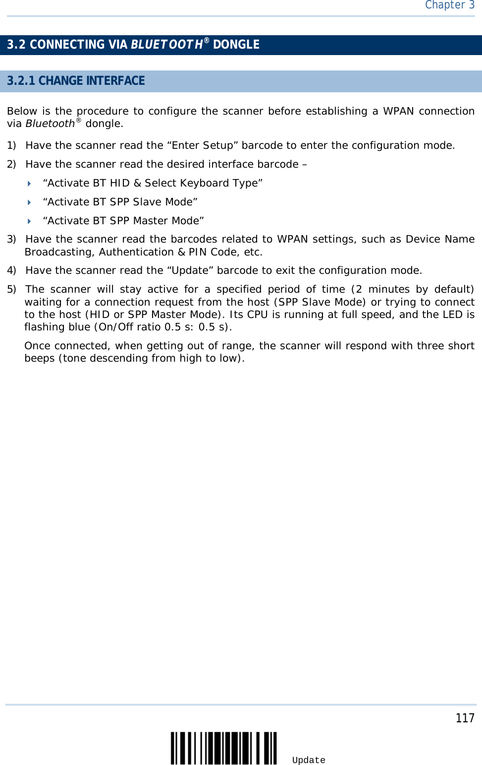
![121 Update Chapter 3 3.2.3 CONNECT TO DONGLE The procedure goes through associating devices for establishing a WPAN connection, which is pretty much the same except for the software you are using. If your computer is running Microsoft® Windows® XP Service Pack 3 (SP3) or Windows Vista® Service Pack 1 (SP1), you can use the software support that Windows® includes, or you can use the driver that the device manufacturer provides. Now, let’s try using the software support that Windows® XP Service Pack 2 includes. BT HID Procedure By default, BT HID is activated on the scanner, and the keyboard type is set to PCAT (US). When BT HID is re-activated, you will have to select a keyboard type to complete this setting. The procedure is the same as for BT SPP. Refer to steps 1~11 below. BT SPP Procedure 1. Turn on the Bluetooth® function on your computer, running Windows XP SP2. 2. Double-click the Bluetooth® icon from the lower right of the taskbar. Alternatively, you may go to Control Panel > Bluetooth Devices. 3. Click [Add] to search devices nearby.](https://usermanual.wiki/CipherLab/1564/User-Guide-1397877-Page-131.png)
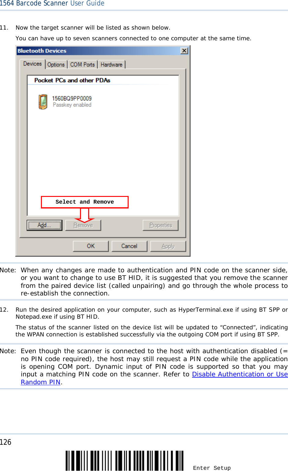
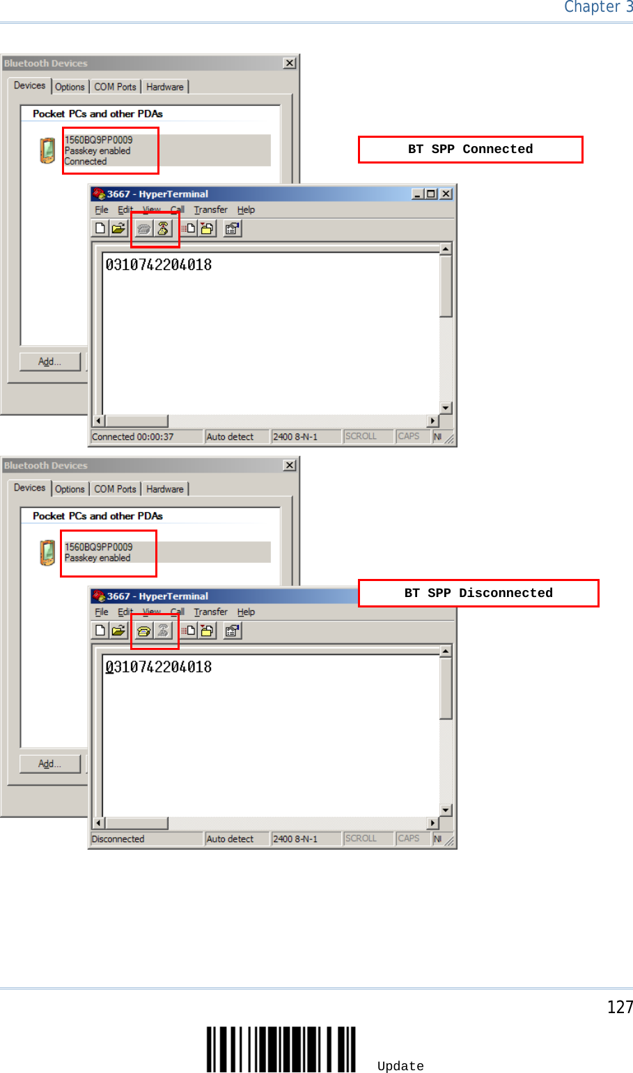
![122 Enter Setup 1564 Barcode Scanner User Guide 4. Turn on the scanner with correct WPAN settings, such as select BT SPP or BT HID, broadcasting enabled, authentication enabled, and PIN code specified, etc. Select the check box of [My device is set up and ready to be found] on your computer. 5. Click [Next]. 6. Wait for a few seconds for the Wizard to search available devices nearby. The scanner will appear with its “serial number” as the device name. You may double-check the “Serial Number” label on the scanner to ensure connecting with the correct scanner. Select the target scanner. If the target scanner does not appear on the list, click [Search Again] to refresh the list. The scanner might enter Suspend Mode now, and you can press the trigger to have it active again (=discoverable). It will then stay active for a specified period of time (2 minutes by default) and wait for PC to establish a connection.](https://usermanual.wiki/CipherLab/1564/User-Guide-1397877-Page-132.png)
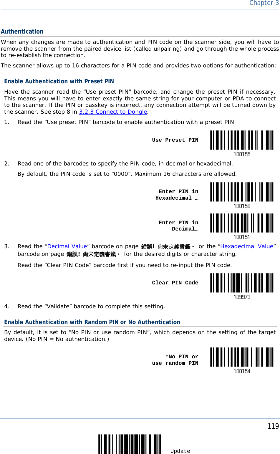
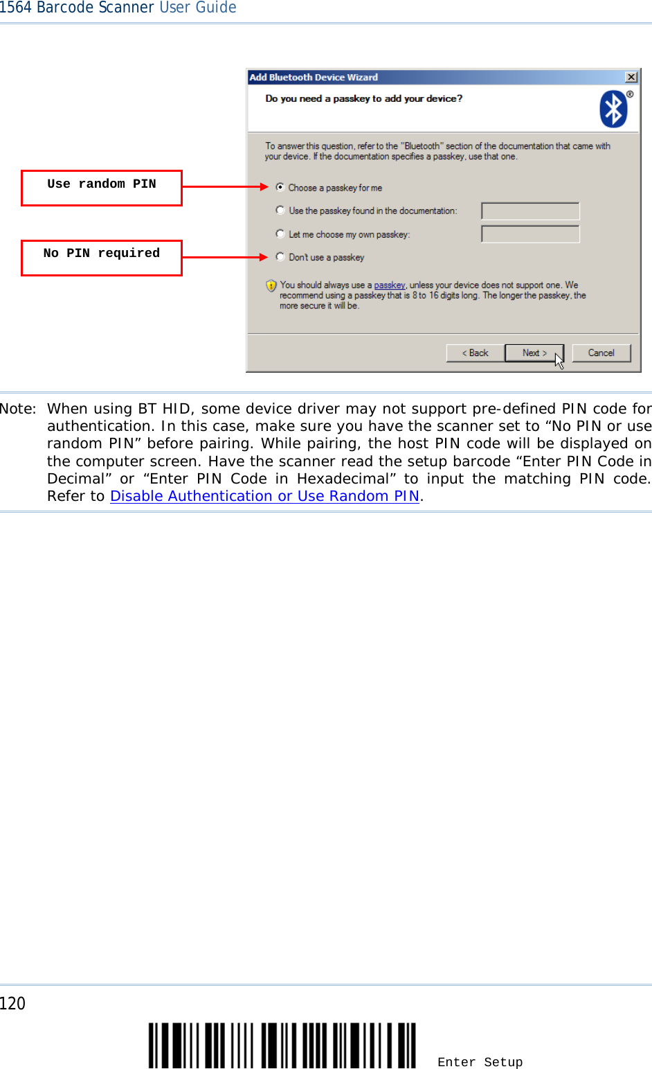
![123 Update Chapter 3 7. Click [Next]. 8. Enter the passkey for authentication, which must be exactly the same as configured for the scanner.](https://usermanual.wiki/CipherLab/1564/User-Guide-1397877-Page-133.png)
![124 Enter Setup 1564 Barcode Scanner User Guide 9. Click [Next]. Wait for a few seconds for Windows to exchange passkeys.](https://usermanual.wiki/CipherLab/1564/User-Guide-1397877-Page-134.png)
![125 Update Chapter 3 Note: When Bluetooth security is enabled without providing a pre-set PIN code, dynamic input of PIN code is supported. 10. Click [Finish]. 1560 as BT SPP Slave 1560 as BT SPP Master](https://usermanual.wiki/CipherLab/1564/User-Guide-1397877-Page-135.png)