CipherLab 1861 Handheld RFID Reader User Manual
CipherLab Co., Ltd. Handheld RFID Reader
UserManual.wiki
>
CipherLab
>
1861 User Manual
User Manual
Navigation menu
Upload a User Manual
Namespaces
Wiki Guide
HTML
PDF
Info
Views
User Manual
Discussion / Help
Navigation


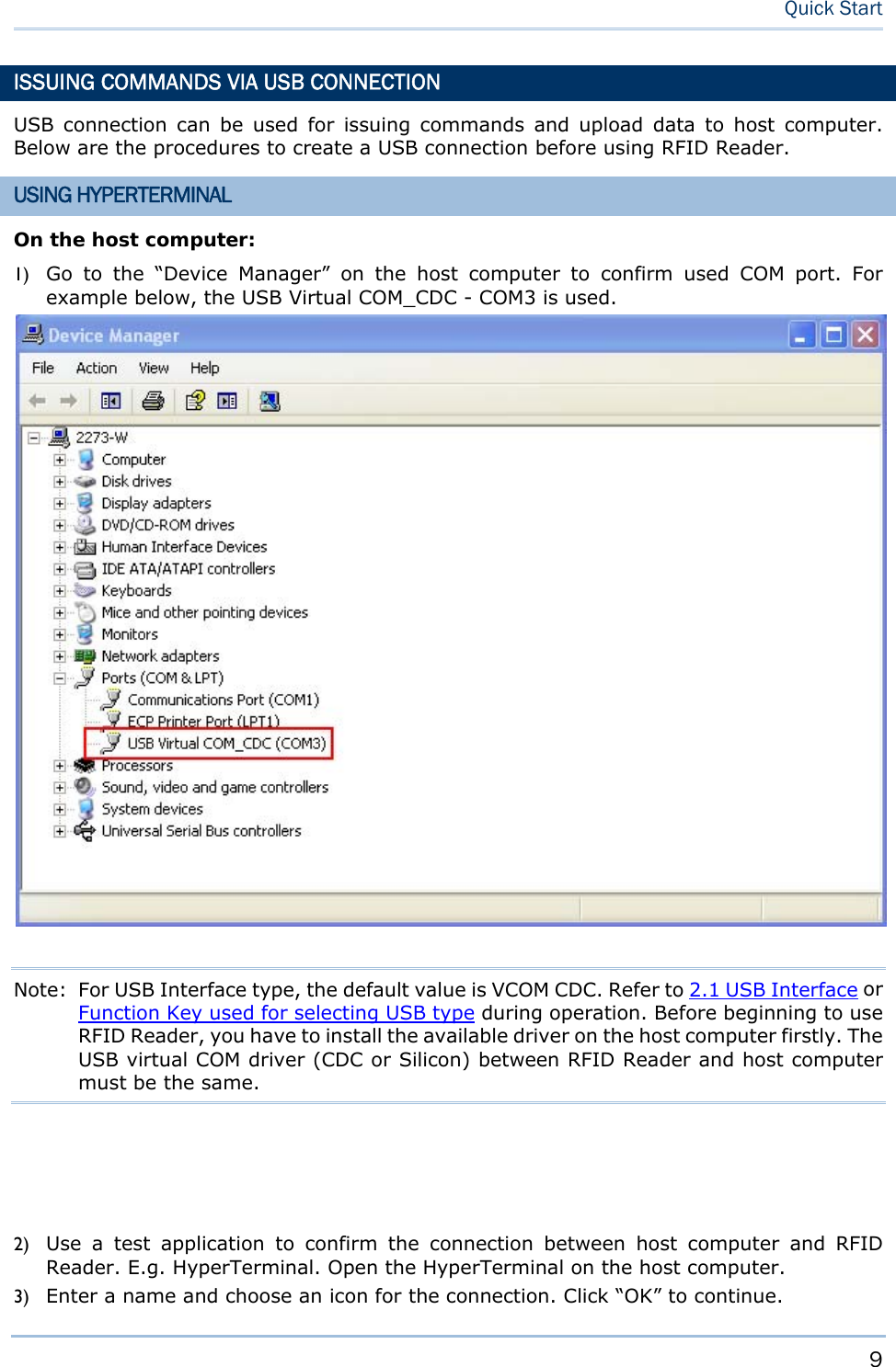
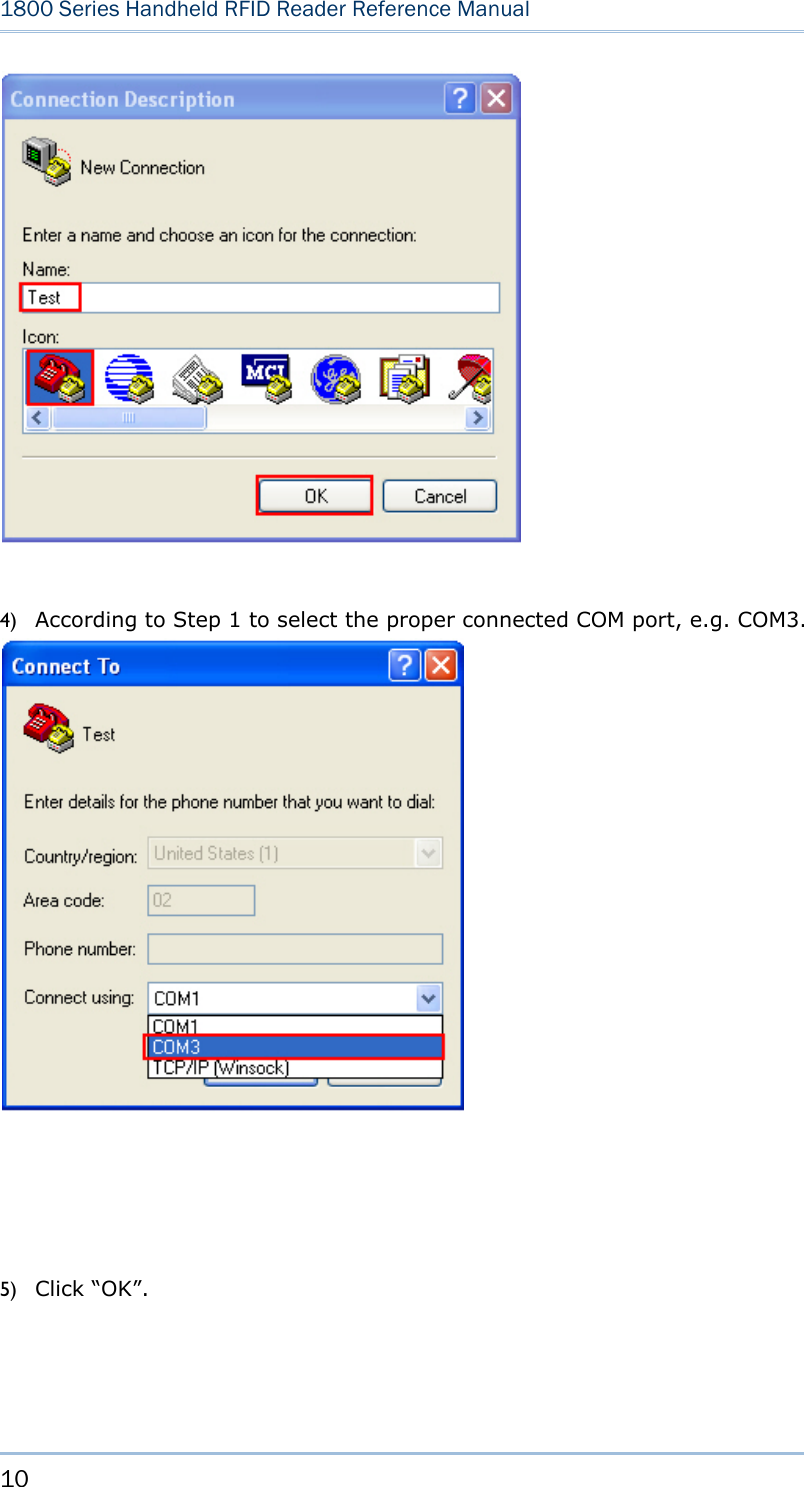
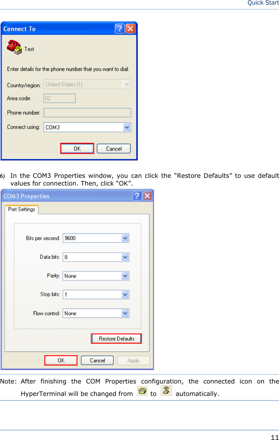
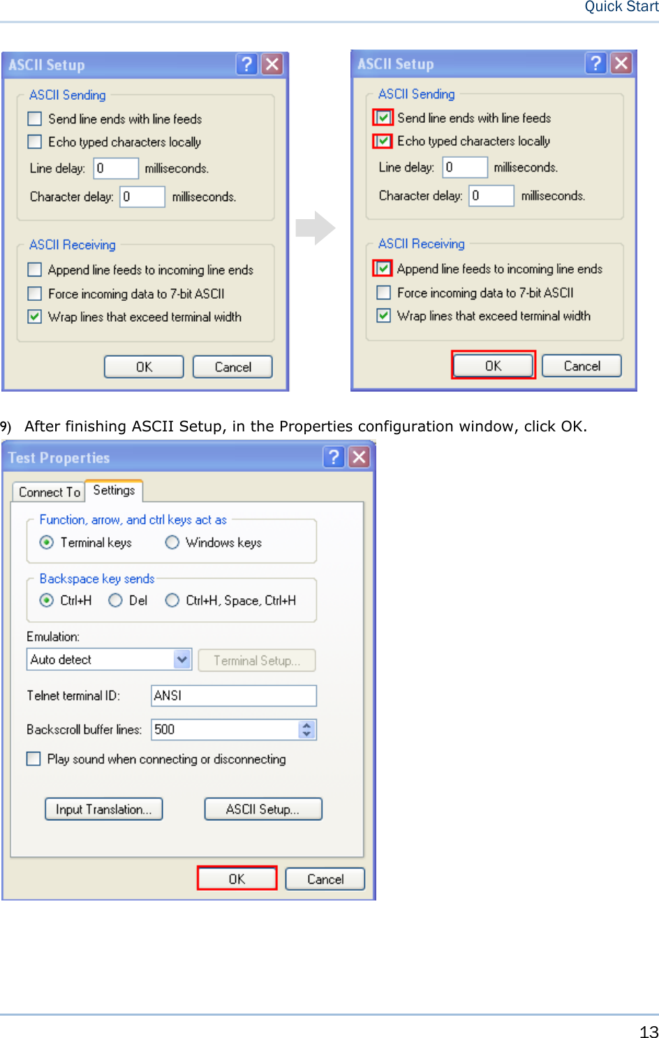
![12 1800 Series Handheld RFID Reader Reference Manual 7) In the HyperTerminal window, click on the tool bar to open Properties configuration window, see below. Click “Settings” tab. 8) Click [ASCII Setup] to open ASCII Setup window and some check boxes need to be selected for normalized issuing commands, see below. Click “OK”.](https://usermanual.wiki/CipherLab/1861/User-Guide-1740510-Page-24.png)
![15 Quick Start DEFAULT SETTINGS SAVE USER SETTINGS AS DEFAULTS For the RFID Reader to keep the customized settings as user defaults, you must issue “#@sys_svusrtbl” command. Note: After issuing the command, the current settings will be saved as user defaults. Command: #@sys_svusrtbl\r Purpose Save User Defined Setting Response OK\r ERR,[code]\r RESTORE USER/FACTORY DEFAULTS For the RFID Reader to restore the User Defaults, which you have saved earlier, you must issue “#@sys_ldstbl=1” command. Alternatively, you can also issue “#@sys_ldstbl=0” command to restore Factory Default. Command: #@sys_ldstbl=[m]\r Purpose Load Default Setting Request #@sys_ldstbl=[m]\r [m]: ‘0’ – Factory Default ‘1’ – User Default Response OK\r ERR,[code]\r Note: Restore the default values will discount the Bluetooth® connection and erase all connected devices.](https://usermanual.wiki/CipherLab/1861/User-Guide-1740510-Page-27.png)
![18 1800 Series Handheld RFID Reader Reference Manual 186XCONFIGURATION You can configure the RFID Reader by issuing commands or 186xConfiguration Utility. For HyperTerminal: You may run HyperTerminal.exe on the host computer to send commands to RFID Reader via USB Cable. The commands are not case sensitive. The example command common format is showed as below: Example: #@sys_time?<CR> Get the system time →information. #@sys_time=[Y],[M],[D],[h],[m],[s]<CR> Set the system time. →[Y],[M],[D],[h],[m],[s] are the parameters of system time. Note: A serial command consists of Prefix, Text and Suffix. The prefix consists of “#” and “@”. “?” or “=” is specified to suffix. \r or <CR> is specified for the “Enter” of your keyboard. For 186xConfiguration Utility: CipherLab supports a Windows®-based Software Utility to allow you to configure RFID Reader easily. For more information, refer to 186xConfiguration User Guide.](https://usermanual.wiki/CipherLab/1861/User-Guide-1740510-Page-30.png)
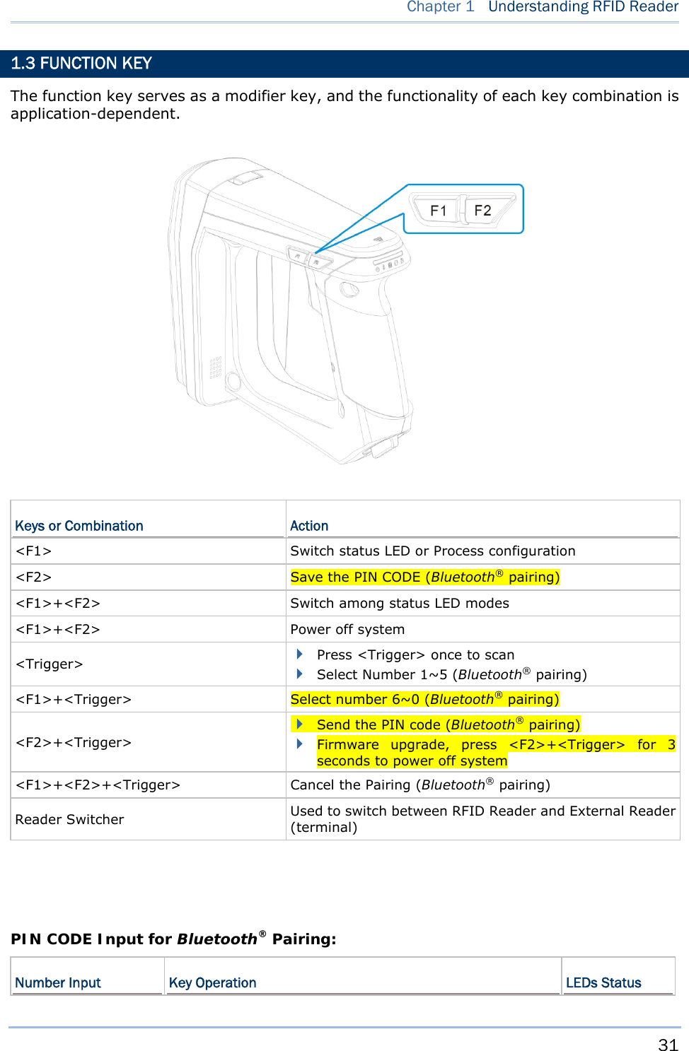
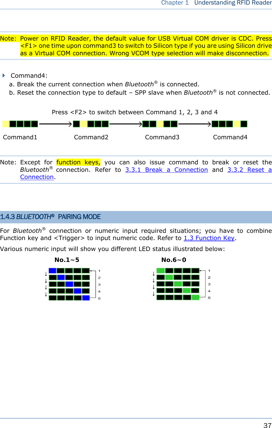
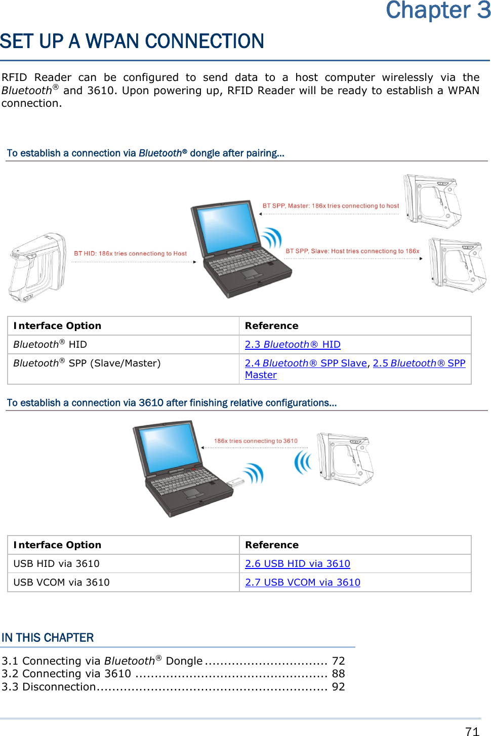
![19 This chapter explains the features and usage of RFID Reader. Before configuring RFID Reader, you have to understand the information by issuing “#@sys_info?” command firstly. Command: #@sys_info?\r Purpose Get System Information Response OK,[m]\r[n]\r[o]\r[p]\r[Q]\r [m]: string that indicates model name “1861E” – Basic UHF type Europe Band “1861U” – Basic UHF type US Band “1861J” – Basic UHF type Japan Band [n]: string that indicates serial number [o]: string that indicates kernel version [p]: string that indicates user version [q]: string that indicates BTMACID ERR,[code]\r Example: IN THIS CHAPTER 1.1 Power ...................................................................... 21 1.2 Memory .................................................................... 24 1.3 Function Key ............................................................. 31 1.4 LED Indicators ........................................................... 33 1.5 Buzzer ..................................................................... 38 1.6 Vibrator .................................................................... 42 1.7 RTC ......................................................................... 43 Chapter 1 UNDERSTANDING RFID READER](https://usermanual.wiki/CipherLab/1861/User-Guide-1740510-Page-31.png)
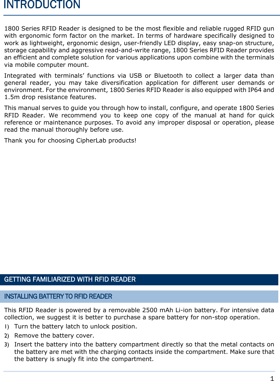
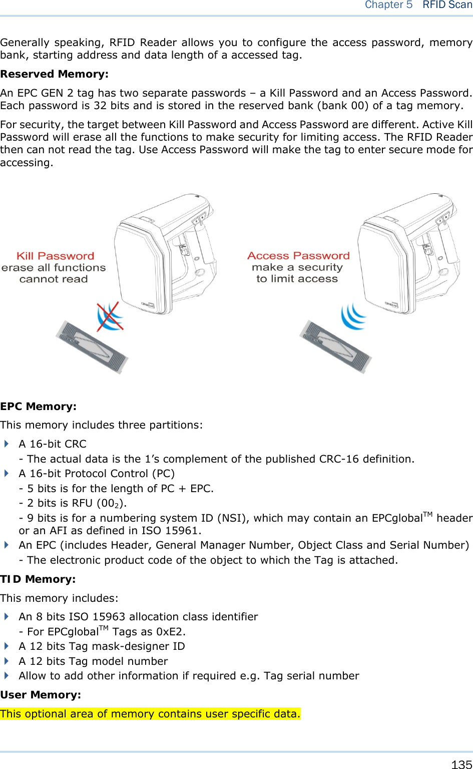
![21 Chapter 1 Understanding RFID Reader 1.1 POWER RFID Reader is powered by a rechargeable 3.7V/2500mAh Li-ion battery pack, and it takes approximately 4 hours to fully charge it via charger or adapter. However, the charging time may vary by working condition. During normal operation, the RFID Reader can work for up to 10 hours. Warning: The battery cover must be in position. If not, the RFID Reader cannot turn on. For a new battery, make sure it is fully charged before you begin to use it. Always prepare a spare batter, especially when you are working on a non-stop operation. 1.1.1 POWER ON After installing the battery, press the <Trigger> for 2 seconds. The RFID Reader will respond with a long beep (high tone), and LED1 will become solid red for 1 second and go off. 1.1.2 POWER OFF The RFID Reader will stay active at power-on, which may be followed by a transition from full CPU speed to low CPU speed (Power-Saving) to auto shutdown (Auto Power Off). You can power off the RFID Reader by pressing both <F1>+<F2> keys or issuing command on the host computer described below. Auto Power Off (1~254 min.; 0= Disable): By default, it is set to automatically shut down after idling 10 minutes. If this feature is not desired, set it to 0. Command: #@sys_off\r Purpose System Shutdown Response OK\r ERR,[code]\r #@sys_tpoff?\r Purpose Get the Delay Time of System Shutdown Response OK,[m]\r (Default m= ‘10’) [m]: ‘0’ ~ ‘254’ (Unit=minute) ERR,[code]\r #@sys_tpoff=[m]\r Purpose Set the Delay Time of System Shutdown Response OK\r ERR,[code]\r If you want to keep system always alive, you can issue “#@sys_kalive” command. If the delay time for system shutdown and power saving mode are not zero, this command will prevent the RFID Reader from entering the power saving mode or shutting down itself.](https://usermanual.wiki/CipherLab/1861/User-Guide-1740510-Page-33.png)
![22 1800 Series Handheld RFID Reader Reference Manual Command: #@sys_kalive\r Purpose Keep the System Alive Response OK\r ERR,[code]\r 1.1.3 POWER SAVING MODE Power Saving (1~254 min.; 0= Disable): By default, it is set to idle at full-speed for 2 minutes before it enters power saving mode. If this feature is not desired, set it to 0. However, the Power Saving setting will not take effect when data is transmitting via Bluetooth® HID or SPP. Command: #@sys_tps?\r Purpose Get the Delay Time of Power Saving Mode](https://usermanual.wiki/CipherLab/1861/User-Guide-1740510-Page-34.png)
![23 Chapter 1 Understanding RFID Reader Response OK,[m]\r (Default m= ‘2’) [m]: ‘0’ ~ ‘254’ (Unit=minute) ERR,[code]\r #@sys_tps=[m]\r Purpose Set the Delay Time of Power Saving Mode Response OK\r ERR,[code]\r Note: Power Saving will not take effect when one of the following conditions is met: (1) RFID Reader is in the configuration mode. (2) The scanning mode is set to Test Mode. (3) The setting value of Power Saving is greater than Auto Power Off. 1.1.4 LOW BATTERY ALARM By default, the battery alarm will beep when the battery charge gets low. In order to prevent data loss, it is advised to replace the battery immediately when hearing two short beeps (high tone). Command: #@sys_battery?\r Purpose Get Voltage of Battery Response OK,[m]\r [m]: battery voltage. (e.g. 100%) ERR,[code]\r #@sys_lbalarm?\r Purpose Get Low Battery Alarm Response OK,[m]\r (Default m= ‘1’) [m]: ‘0’ – Disable ‘1’ – Enable ERR,[code]\r #@sys_lbalarm=[m]\r Purpose Set Low Battery Alarm Response OK\r ERR,[code]\r Warning: Using Bluetooth® connection will substantially reduce battery power. Disable the Bluetooth® function when it is uselessly.](https://usermanual.wiki/CipherLab/1861/User-Guide-1740510-Page-35.png)
![26 1800 Series Handheld RFID Reader Reference Manual Command: #@sys_txben?\r Purpose Get Transmission Buffer Status Response OK,[m]\r (Default m= ‘1’) [m]: ‘0’ – Disable ‘1’ – Enable ERR,[code]\r #@sys_txben=[m]\r Purpose Set Transmission Buffer Status Response OK\r ERR,[code]\r #@sys_txbdly?\r Purpose Get Transmission Buffer Delay Response OK,[m]\r (Default m= ‘0’) [m] Send TX Buffer Delay ‘0’ 0 ms ‘1’ 250 ms ‘2’ 500 ms ‘3’ 1 sec ‘4’ 2 sec ‘5’ 3 sec ‘6’ 5 sec ‘7’ 8 sec ERR,[code]\r #@sys_txbdly=[m]\r Purpose Set Transmission Buffer Delay Response OK\r ERR,[code]\r](https://usermanual.wiki/CipherLab/1861/User-Guide-1740510-Page-38.png)
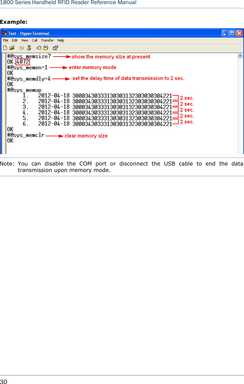
![27 Chapter 1 Understanding RFID Reader 1.2.2 MEMORY MODE The RFID Reader keeps 4MB memory for memory mode operation. When the RFID Reader is in memory mode with green LED5 flashing and blue LED2 off that means any real-time connection established with the host is disabled. Warning: No real-time connection is allowed unless the memory mode is disabled. STATUS You have to disable the memory mode to allow a real-time connection. And confirm the memory size by issuing “#@sys_memsize?” command. Command: #@sys_memen?\r Purpose Get Memory Mode Status Response OK,[m]\r (Default m= ‘0’) [m]: ‘0’ – Disable ‘1’ – Enable ERR,[code]\r #@sys_memen=[m]\r Purpose Set Memory Mode Response OK\r ERR,[code]\r Note: You can also enter/exit memory mode by pressing function key. Refer to 1.4.2 Temporary Mode. #@sys_memsize?\r Purpose Get Free Memory Size Response OK,[m]\r (Default m is 4072) [m]: Free Memory Size string in KB ERR,[code]\r DATA DELAY You may set a delay time between each data record while transmitting data back to the host computer.](https://usermanual.wiki/CipherLab/1861/User-Guide-1740510-Page-39.png)
![28 1800 Series Handheld RFID Reader Reference Manual Command: #@sys_memdly?\r Purpose Get Data Transmission Delay Response OK,[m]\r (Default m= ‘0’) [m]: ‘0’~’7’ Data Transmission Delay Value Delay ‘0’ 0 ms ‘1’ 250 ms ‘2’ 500 ms ‘3’ 1 sec ‘4’ 2 sec ‘5’ 3 sec ‘6’ 5 sec ‘7’ 8 sec ERR,[code]\r #@sys_memdly=[m]\r Purpose Set Data Transmission Delay Response OK\r ERR,[code]\r SEND DATA The RFID Reader will respond with two short beeps (high-low tone) as a warning when sending data. You are advised to send data to the host computer immediately by issuing “#@sys_memup” command. The RFID Reader will restore the previous connection with the host computer temporarily so that you can transmit data to the host computer. Command:](https://usermanual.wiki/CipherLab/1861/User-Guide-1740510-Page-40.png)
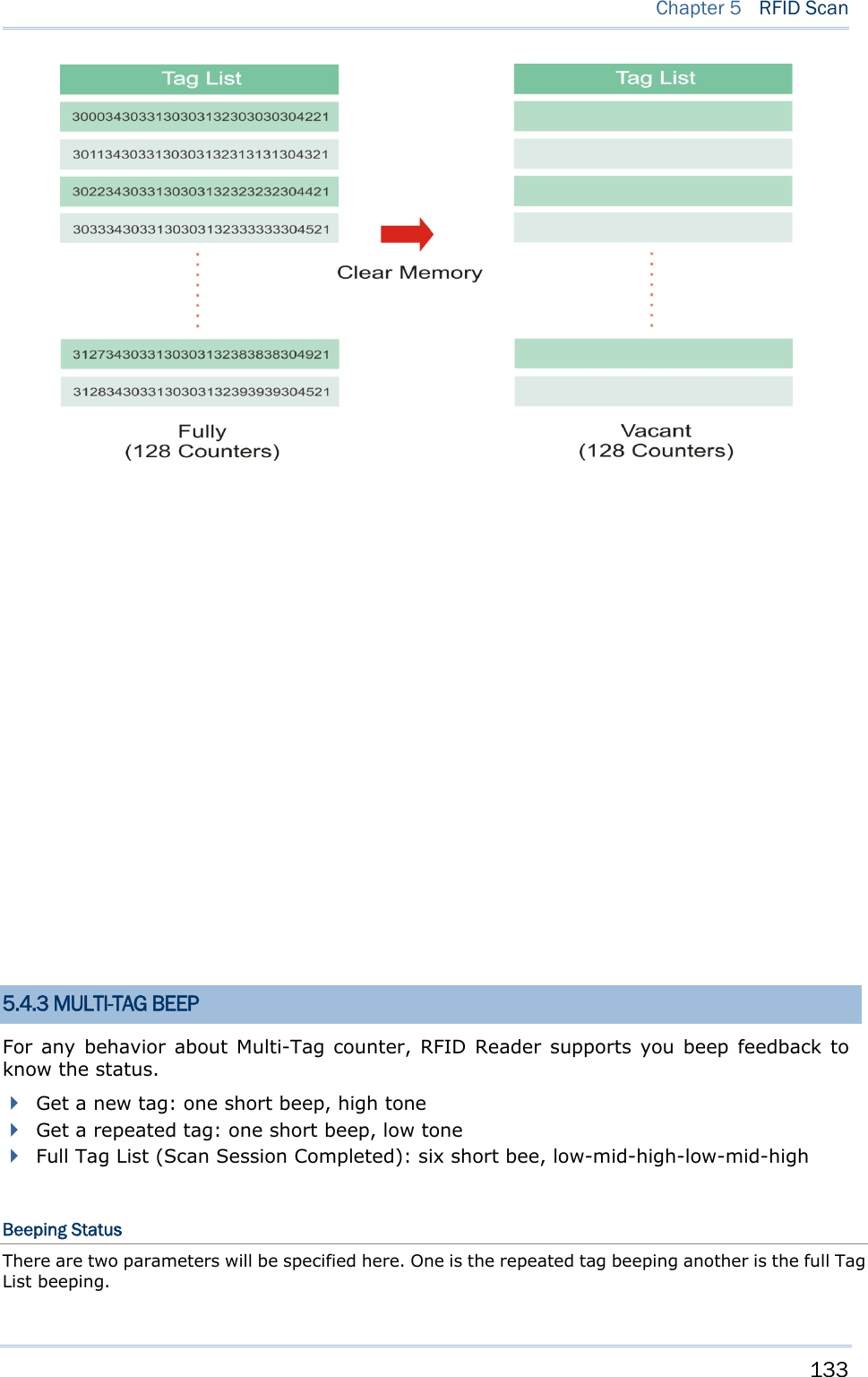
![29 Chapter 1 Understanding RFID Reader #@sys_memup\r Purpose Upload Memory Data Request #@sys_memup\r OK,[m]\r [m]: Data string Response OK\r ERR,[code]\r CLEAR MEMORY Even though data has been sent back to the host, the flash memory is still occupied unless you erase the memory by issuing “#@sys_memclr” command to clear memory. Note: The bluetooth® connection will be broken once entering the memory mode. Command: #@sys_memclr\r Purpose Clear Memory Response OK\r ERR,[code]\r](https://usermanual.wiki/CipherLab/1861/User-Guide-1740510-Page-41.png)
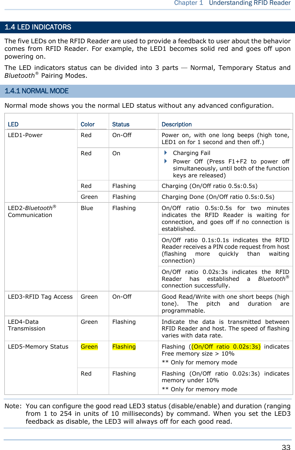
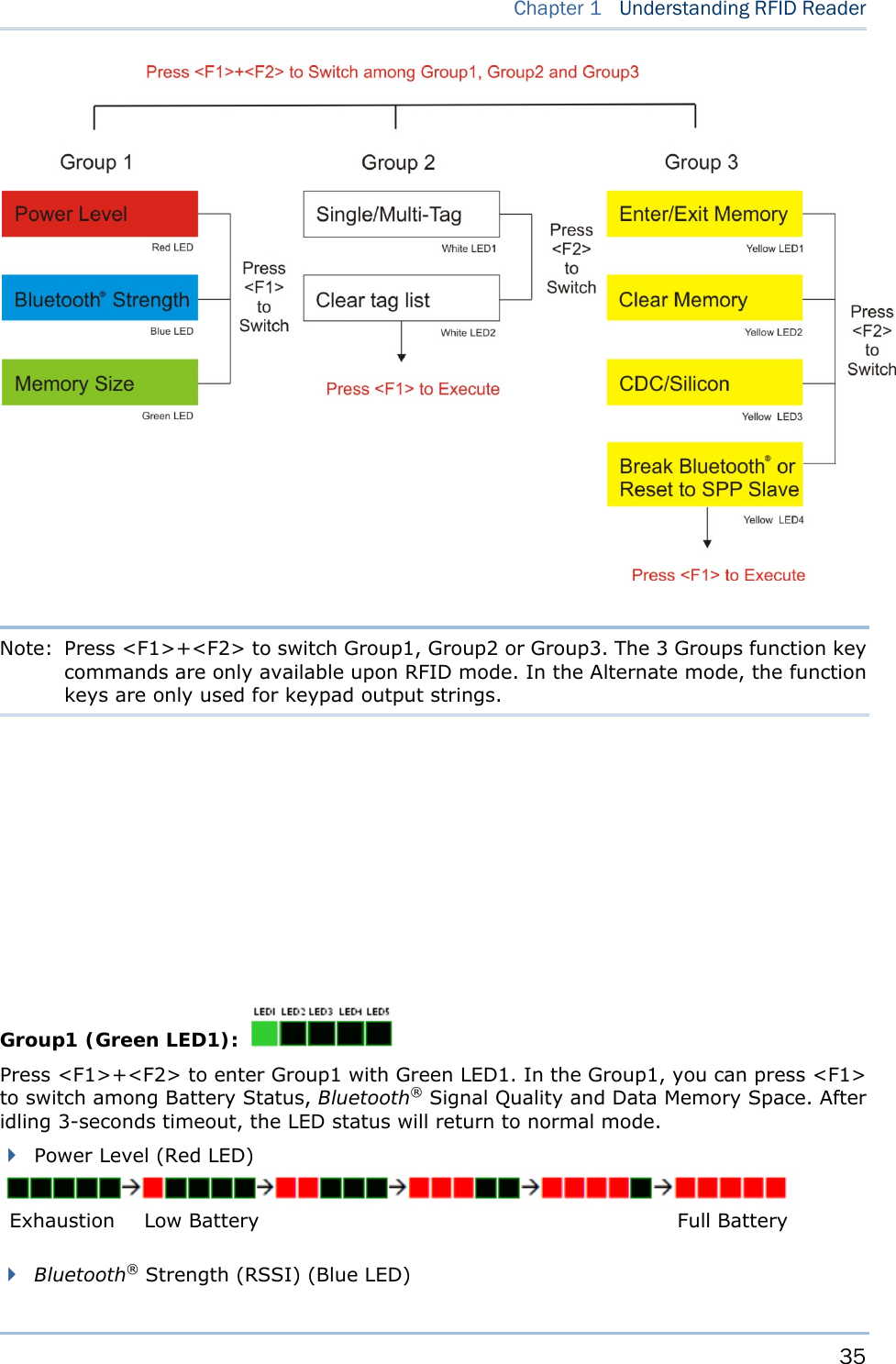
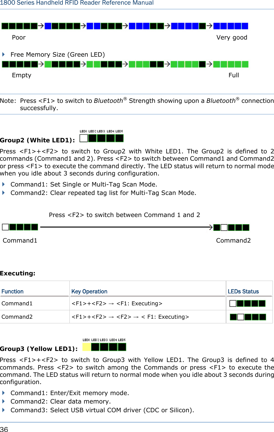
![34 1800 Series Handheld RFID Reader Reference Manual GOOD READ LED STATUS You may configure the LED3 status for a feedback about good read. Command: #@sys_leden?\r Purpose Get Good Read LED Status Response OK,[m]\r (Default m= ‘1’) [m]: ‘0’ – Disable ‘1’ – Enable ERR,[code]\r #@sys_leden=[m]\r Purpose Set LED Good Read Status Response OK\r ERR,[code]\r GOOD READ LED DURATION For a good read for LED3, you may configure the duration time. Command: #@sys_leddu?\r Purpose Get Good Read LED Duration Response OK,[m]\r (Default m= ‘4’) [m]: Duration=‘1’ ~ ‘254’ ERR,[code]\r #@sys_leddu=[m]\r Purpose Set LED Duration Response OK\r ERR,[code]\r 1.4.2 TEMPORARY MODE In this mode, combine with five LEDs and function keys, the LED status can be classified into 3 Groups that are described below, also refer to 1.3 Function Key.](https://usermanual.wiki/CipherLab/1861/User-Guide-1740510-Page-46.png)
![39 Chapter 1 Understanding RFID Reader The battery is removed during charging When the battery voltage is under 5%, it will continual beeps. We suggest it is better to charge the battery immediately before the RFID Reader is powered off. You can get the voltage information by issue “sys_battery?” command. The commands below describe the buzzer related configurations: VOLUME There are four volume levels defined to beeping setting. Command: #@sys_bpvol?\r Purpose Get Beeper Volume Response OK,[m]\r (Default m= ‘High’) [m]: Volume ‘0’ Mute ‘1’ Low ‘2’ Medium ‘3’ High ERR,[code]\r #@sys_bpvol=[m]\r Purpose Set Beeper Volume Response OK\r ERR,[code]\r COMMAND BEEP By default, this function is enabled. Command: #@sys_cmdbp?\r Purpose Get Status of Command Indicating Beep Response OK,[m]\r (Default m= ‘0’) [m]: ‘0’ – Disable ‘1’ – Enable ERR,[code]\r](https://usermanual.wiki/CipherLab/1861/User-Guide-1740510-Page-51.png)
![40 1800 Series Handheld RFID Reader Reference Manual #@sys_cmdbp=[m]\r Purpose Set Command indicating Beep Response OK\r ERR,[code]\r GOOD READ You have to enable the buzzer beeping function when you want to get a feedback from RFID Reader. Command: #@sys_grdbp?\r Purpose Get Status of Good-Read Beep Response OK,[m]\r (Default m= ‘1’) [m]: ‘0’ – Disable ‘1’ – Enable ERR,[code]\r #@sys_grdbp=[m]\r Purpose Set Status of Good-Read Beep Response OK\r ERR,[code]\r FREQUENCY By default, the frequency for a buzzer is configured to 4KHz. This function is upon Good-Read beep is enabled. Command: #@sys_grdbf?\r Purpose Get Beeper Frequency Response OK,[m]\r (Default m= ‘1’) [m]: Frequency ‘0’ 8 kHz ‘1’ 4 kHz ‘2’ 2 kHz ‘3’ 1 kHz ERR,[code]\r #@sys_grdbf=[m]\r Purpose Set Beeper Frequency Response OK\r](https://usermanual.wiki/CipherLab/1861/User-Guide-1740510-Page-52.png)
![41 Chapter 1 Understanding RFID Reader ERR,[code]\r DURATION You can configure the beeping duration to shortest, short, longer or longest. This function is upon Good-Read beep is enabled. Command: #@sys_grdbdu?\r Purpose Get Beeper Duration Response OK,[m]\r (Default m= ‘Shortest’) [m]: Duration ‘0’ Shortest ‘1’ Short ‘2’ Longer ‘3’ Longest ERR,[code]\r #@sys_grdbdu=[m]\r Purpose Set Beeper Duration Response OK\r ERR,[code]\r Note: When you set the volume of beeper to mute, the feedback from RFID Reader will be mute.](https://usermanual.wiki/CipherLab/1861/User-Guide-1740510-Page-53.png)
![42 1800 Series Handheld RFID Reader Reference Manual 1.6 VIBRATOR The RFID Reader has a built-in vibrator, which can be issued command for feedback. This can be helpful when working in noisy environments. For good read/write, the vibrator will make the duration of 1 second feedback with on-off vibrating. The vibrating and duration are programmable. STATUS RFID Reader supports a good feedback with mute vibrator, you can enable/disable by issuing “#@sys_viben=” command. Command: #@sys_viben?\r Purpose Get Vibrator Status Response OK,[m]\r (Default m= ‘0’) [m]: ‘0’ – Disable ‘1’ – Enable ERR,[code]\r #@sys_viben=[m]\r Purpose Set Vibrator Status Response OK\r ERR,[code]\r DURATION By default, the good reader vibrator stays on for 1 second. Specify a value, ranging from 1 to 254 in units of 100 milliseconds. Command: #@sys_vibdu?\r Purpose Get Vibrator Duration Response OK,[m]\r (Default m= ‘10’) [m]: Duration=‘1’ ~ ‘254’ ERR,[code]\r #@sys_vibdu=[m]\r Purpose Set Vibrator Duration Response OK\r ERR,[code]\r](https://usermanual.wiki/CipherLab/1861/User-Guide-1740510-Page-54.png)
![43 Chapter 1 Understanding RFID Reader 1.7 RTC RFID Reader supports a system clock to keep track of the current time. Command: #@sys_time?\r Purpose Get System Clock Response OK,[Y],[M],[D],[h],[m],[s]\r [Y]: ‘00’ ~ ‘99’ [M]: ‘01’ ~ ‘12’ [D]: ‘01’ ~ ‘31’ [h]: ‘00’ ~ ‘23’ [m]: ‘00’ ~ ‘59’ [s]: ‘00’ ~ ‘59’ ERR,[code]\r #@sys_time=[Y],[M],[D],[h],[m],[s]\r Purpose Set System Clock Response OK\r ERR,[code]\r Example:](https://usermanual.wiki/CipherLab/1861/User-Guide-1740510-Page-55.png)
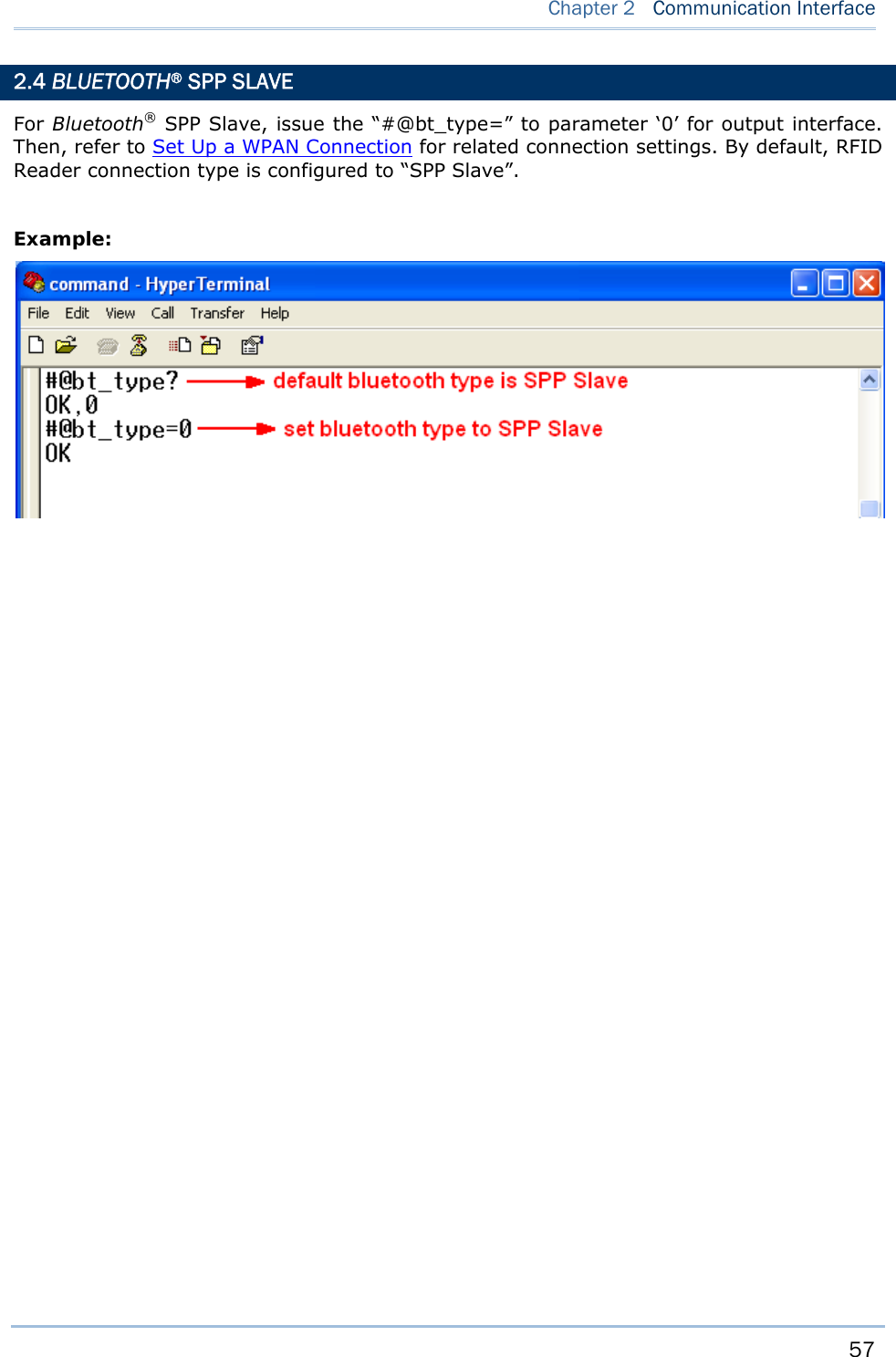
![46 1800 Series Handheld RFID Reader Reference Manual 2.1 USB INTERFACE Create a connection between RFID Reader and host computer; you have to select the available USB interface type by “#@usb_type=” command. Wrong USB interface type setting will make disconnection. You can also use the function key to switch the USB interface type, refer to 1.4.2 Temporary Mode. Command: #@usb_type?\r Purpose Get USB Interface Type Response OK,[m]\r (Default m=‘127’) [m]: USB Type ‘127’ – Virtual COM CDC ‘128’ – Virtual COM (Silicon Lab driver) ERR,[code]\r #@usb_type=[m]\r Purpose Set USB Interface Response OK\r ERR,[code]\r 2.2 BLUETOOTH® CONNECTION TYPE Based on the connection type, you have to select the proper Bluetooth® type. By default, the connection type is configured to “SPP Slave”. Command:](https://usermanual.wiki/CipherLab/1861/User-Guide-1740510-Page-58.png)
![47 Chapter 2 Communication Interface #@bt_type?\r Purpose Get Bluetooth® Interface Type Response OK,[m]\r (Default m= ’0’) [m]: Bluetooth® TYPE Bluetooth® Type Description Read only / R/W ‘0’ SPP Slave R/W ‘3’ SPP Master R/W ‘5’ HID R/W ‘6’ 3610 Read only ERR,[code]\r #@bt_type=[m]\r Purpose Set Bluetooth® Interface Type Response OK\r ERR,[code]\r](https://usermanual.wiki/CipherLab/1861/User-Guide-1740510-Page-59.png)
![49 Chapter 2 Communication Interface Command: #@bt_hididx?\r Purpose Get Bluetooth® HID Parameter Response OK,[m]\r [m]: Parameter [m] Description Valid Parameters ‘0’ HID KBD Type ‘64’~ ‘77’ (Default m=‘64’) ‘3’ Inter-function Delay ‘0’ ~ ‘254’ (Default m=‘0’) ‘4’ Inter-character Delay ‘0’ ~ ‘254’ (Default m=‘0’) ‘5’ Caps Lock State ‘0’ – OFF (Default m=‘0’) ‘1’ – ON ‘2’ – Auto ‘7’ Alphabets Transmission ‘0’ – Case Sensitive ‘1’ – Ignore Case ‘8’ Digits Transmission ‘0’ – Alpha Numeric Keypad ‘1’– Numeric Keypad ‘9’ Digits Position ‘0’ – Normal ‘1’– Lower Row ‘2’– Upper Row ‘10’ Keyboard Layout ‘0’ – Normal ‘1’ – AZERTY ‘2’ – QWERTZ ‘12’ HID Character Transmit Mode ‘0’ – Batch Processing ‘1’ – By Character ERR,[code]\r #@bt_hididx=[m]\r Purpose Set Bluetooth® HID Parameter Response OK\r\r ERR,[code]](https://usermanual.wiki/CipherLab/1861/User-Guide-1740510-Page-61.png)
![50 1800 Series Handheld RFID Reader Reference Manual #@bt_hidpr?\r Purpose Get Bluetooth® HID Parameter Response OK,[m]\r [m]: Parameter ERR,[code]\r #@bt_hidpr=[m]\r Purpose Set Bluetooth® HID Parameter Response OK\r ERR,[code]\r Example:](https://usermanual.wiki/CipherLab/1861/User-Guide-1740510-Page-62.png)
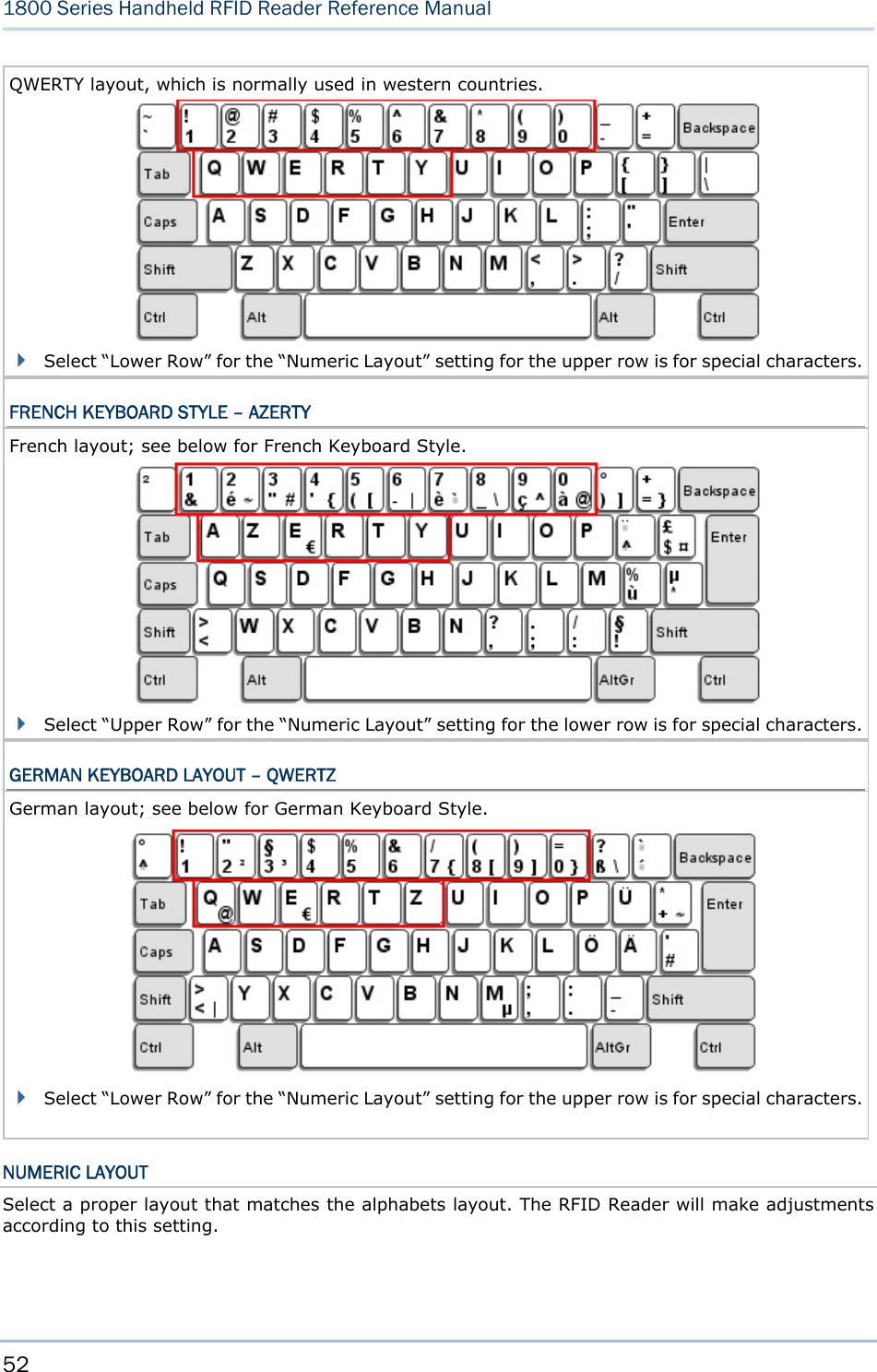
![53 Chapter 2 Communication Interface Options Parameter Description Normal (Default) ‘0’ Depend on the [Shift] key or [Shift Lock] setting. Lower Row ‘1’ For QWERTY or QWERTZ keyboard. Upper Row ‘2’ For AZERTY keyboard. Note: This setting is to be used with the Character Substitution setting when support to certain keyboard types (languages) is unavailable but required. CAPITAL LOCK SETTING In order to send the alphabets with correct case, the RFID Reader needs to know the status of Caps Lock on the keyboard. Incorrect settings may result in reversed case of the alphabets being transmitted. Options Parameter Description Capital Lock OFF (Default) ‘0’ Assuming that the status of Caps Lock on the keyboard is OFF, transmitted characters are exactly the same as in the tag (when "case-sensitive" is selected for Alphabets Transmission). Capital Lock ON ‘1’ Assuming that the status of Caps Lock on the keyboard is ON, transmitted characters are exactly the same as in the tag (when "case-sensitive" is selected for Alphabets Transmission). Refer to the Capital Lock Type above. Auto Detection ‘2’ The RFID Reader will automatically detect the status of Caps Lock on the keyboard before data is transmitted; transmitted characters are exactly the same as in the tag (when "case-sensitive" is selected for Alphabets Transmission). ALPHABETS TRANSMISSION By default, the alphabets transmission is case-sensitive, meaning that the alphabets will be transmitted according to their original case, the status of Caps Lock on the keyboard, as well as the Capital Lock setting. Select [Ignore Case] to have alphabets transmitted according to the status of Caps Lock on the keyboard only.](https://usermanual.wiki/CipherLab/1861/User-Guide-1740510-Page-65.png)
![58 1800 Series Handheld RFID Reader Reference Manual 2.5 BLUETOOTH® SPP MASTER As a SPP master device, RFID Reader will be able to resume connection with the host computer upon powering on again, as long as the host application is running. If RFID Reader fails to resume connection, it will try every 5 seconds to re-connect to the host computer unless you issue the “#@bt_reset” or “#@sys_ldstbl=” command. For Bluetooth® SPP Master Connection, refer to 3.1.4 Bluetooth® SPP Master. Note: In SPP Master Mode, RFID Reader has to connect within the specified period of time (2 minutes by default). During the connection, the RFID Reader will enter to Power Saving Mode to save power. It will automatically power off when the time is up. Refer to 1.1 Power. 2.5.1 ACTIVATE BLUETOOTH® SPP MASTER MODE Configure the output interface to SPP Master by issuing the “bt_type=” and to parameter ‘3’. How to connect with the target machine? There are two parameters for “#@bt_target=” command to SPP Master target machine. One is Bluetooth® targe – SPP Master and another is the symbolical No. of target machine. Command: #@bt_target?\r Purpose Get Bluetooth® Target Machine Response OK,[m],[n]\r [m]: Bluetooth® Type, ‘0’ – SPP Master, ‘1’ – 3610 [n]: MACID of target Machine or S/N of 3610 ERR,[code]\r #@bt_target=[m],[n]\r Purpose Set Bluetooth® Target Machine Response OK ERR,[code] Exit SPP Master Mode To stop such re-connection, you can issue the “#@bt_reset” or “#@sys_ldstbl=” command so that the current connection record (= MACID) will be cleared. Then, the RFID Reader will restart itself automatically. Go through the whole process in Set Up a WPAN Connection to establish a new WPAN connection.](https://usermanual.wiki/CipherLab/1861/User-Guide-1740510-Page-70.png)
![59 Chapter 2 Communication Interface 2.6 USB HID VIA 3610 For USB HID via 3610, connect 3610 to the USB port of host computer, and then connect RFID Reader to 3610 via Bluetooth®. Configure the interface to USB HID via 3610 by issuing the “#@bt_type=” command to parameter ‘6’. To capture the data run any text editor on host computer. The scanned data will be transmitted to the host computer. Note: As above for a read only interface, you can not issue “#@BT_TYPE=” command to change the Bluetooth® interface to 3610 directly by command. How to connect with the 3610? There are two parameters for “#@bt_target” command to 3610. One is Bluetooth® target – 3610 and another is the serial No. of 3610. Command: #@bt_target?\r Purpose Get Bluetooth® Target Machine Response OK,[m],[n]\r [m]: Bluetooth® Type, ‘0’ – SPP Master, ‘1’ – 3610 [n]: MACID of target Machine or S/N of 3610 ERR,[code]\r #@bt_target=[m],[N]\r Purpose Set Bluetooth® Target Machine Response OK\r ERR,[code]\r Example: HID Settings Defaults Keyboard Type PCAT (US) Alphabets Layout Normal](https://usermanual.wiki/CipherLab/1861/User-Guide-1740510-Page-71.png)
![61 Chapter 2 Communication Interface Command: #@bt_aclidx?\r Purpose Get Bluetooth® 3610 Parameter Response OK,[m]\r [m]: Parameter [m] Description Valid Parameters ‘0’ 3610 Type ‘096’ ~ ‘110’ ‘3’ Inter-function Delay ‘0’ ~ ‘254’ (Default m=‘0’) ‘4’ Inter-character Delay ‘0’ ~ ‘254’ ‘5’ Caps Lock State ‘0’ – OFF ‘1’ – ON ‘2’ – Auto ‘7’ Alphabets Transmission ‘0’ – Case Sensitive ‘1’ – Ignore Case ‘8’ Digits Transmission ‘0’ – Alpha Numeric Keypad ‘1’– Numeric Keypad ‘9’ Digits Position ‘0’ – Normal ‘1’– Lower Row ‘2’– Upper Row ‘10’ Keyboard Layout ‘0’ – Normal ‘1’ – AZERTY ‘2’ – QWERTZ ‘12’ HID Character Transmit Mode ‘0’– Batch Processing ‘1’– By Character ERR,[code] #@bt_aclidx=[m]\r Purpose Set Bluetooth® 3610 Parameter Response OK\r ERR,[code]\r #@bt_aclpr?\r Purpose Get Bluetooth® 3610 Parameter Response OK,[m]\r [m]: Parameter ERR,[code]\r #@bt_aclpr=[m]\r Purpose Set Bluetooth® 3610 Parameter Response OK\r](https://usermanual.wiki/CipherLab/1861/User-Guide-1740510-Page-73.png)
![62 1800 Series Handheld RFID Reader Reference Manual ERR,[code]\r #@bt_aclact\r Purpose Activate Bluetooth® 3610 Setting Request #@bt_aclact\r [m]: Parameter Response OK\r ERR,[code]\r](https://usermanual.wiki/CipherLab/1861/User-Guide-1740510-Page-74.png)
![65 Chapter 2 Communication Interface Options Parameter Description Normal (Default) ‘0’ Depends on the [Shift] key or [Shift Lock] setting Lower Row ‘1’ For QWERTY or QWERTZ keyboard Upper Row ‘2’ For AZERTY keyboard Note: This setting is to be used with the Character Substitution setting when support to certain keyboard types (languages) is unavailable but required. CAPITAL LOCK SETTING In order to send the alphabets with correct case, RFID Reader needs to know the status of Caps Lock on the keyboard. Incorrect settings may result in reversed case of the alphabets being transmitted. Status Options Parameter Description Capital Lock OFF (Default) ‘0’ Assuming that the status of Caps Lock on the keyboard is OFF, transmitted characters are exactly the same as in the tag (when "case-sensitive" is selected for Alphabets Transmission). Capital Lock ON ‘1’ Assuming that the status of Caps Lock on the keyboard is ON, transmitted characters are exactly the same as in the tag (when "case-sensitive" is selected for Alphabets Transmission). Refer to the Capital Lock Type above. Auto Detection ‘2’ RFID Reader will automatically detect the status of Caps Lock on the keyboard before data is transmitted; transmitted characters are exactly the same as in the tag (when "case-sensitive" is selected for Alphabets Transmission). ALPHABETS TRANSMISSION By default, the alphabets transmission is case-sensitive, meaning that the alphabets will be transmitted according to their original case, the status of Caps Lock on the keyboard, as well as the Capital Lock setting. Select [Ignore Case] to have alphabets transmitted according to the status of Caps Lock on the keyboard only.](https://usermanual.wiki/CipherLab/1861/User-Guide-1740510-Page-77.png)
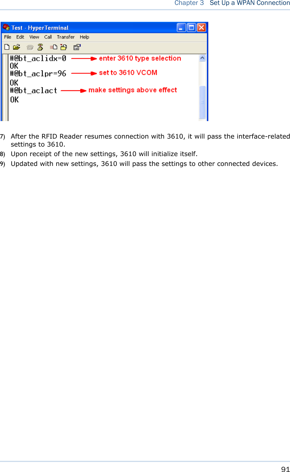
![69 Chapter 2 Communication Interface 2.7 USB VCOM VIA 3610 Connect 3610 to the USB port of host computer, and then connect RFID Reader to 3610 via Bluetooth®. Configure the output interface to USB VCOM via 3610 by issuing the “#@bt_type=” command to parameter ‘6’. You may run HyperTerminal.exe on the host computer to view and capture the data transmission from RFID Reader. Note: As above for a read only interface, you can not issue “#@bt_type=” command to change the Bluetooth® interface to 3610 directly by command. How to connect with the 3610? There are two parameters for “#@bt_target” command to 3610. One is Bluetooth® type and another is the serial No. of 3610. Command: #@bt_target?\r Purpose Get Bluetooth® Target Machine Response OK,[m],[n]\r [m]: Bluetooth® Type, ‘0’ – SPP Master, ‘1’ – 3610 [n]: MACID of target Machine or S/N of 3610 ERR,[code]\r #@bt_target=[m],[N]\r Purpose Set Bluetooth® Target Machine Response OK\r ERR,[code]\r Example: Note: If you are using USB VCOM for the first time, you must install its driver from the CD-ROM. Driver version 5.4 or later is required. Please remove older versions before installing new ones! For a COM Port connection, you have to configure the USB interface type firstly by “#@usb_type=” command. Wrong USB interface type configured will make disconnection. Refer to 2.1 USB Interface.](https://usermanual.wiki/CipherLab/1861/User-Guide-1740510-Page-81.png)
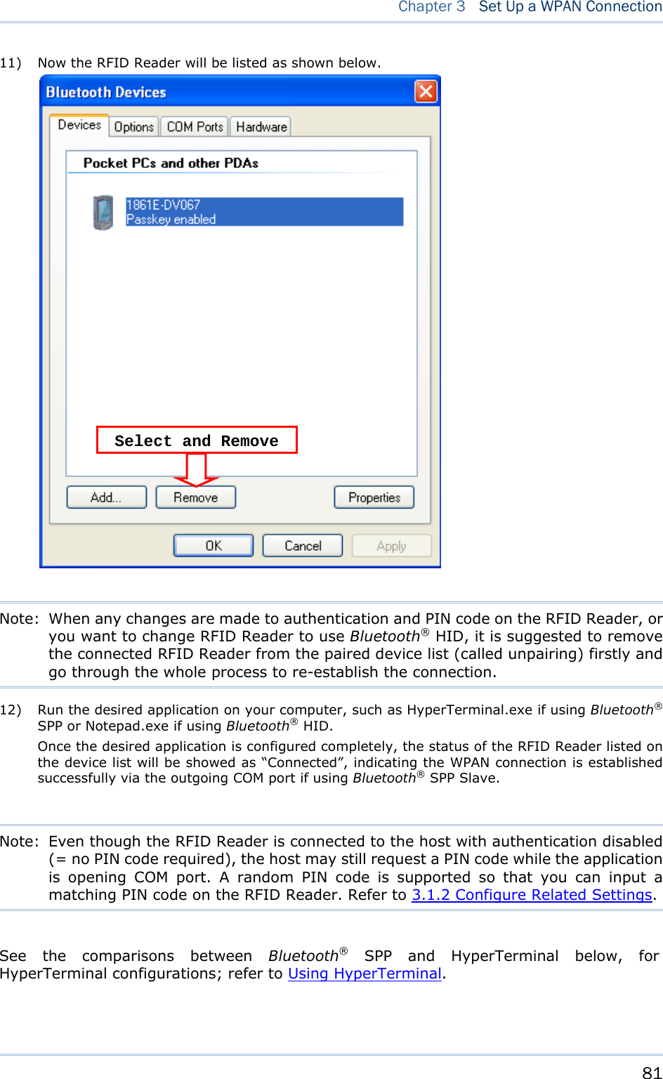
![73 Chapter 3 Set Up a WPAN Connection 3.1.2 CONFIGURE RELATED SETTINGS BROADCASTING RFID Reader can be configured to hide itself from other devices equipped with Bluetooth® wireless technology. Simply disable the device name broadcasting setting so that it won’t be discovered by any other computer. However, broadcasting must be enabled for establishing an initial connection with RFID Reader. For example, disable device name broadcasting after successfully connecting RFID Reader to one WorkStation. Such connection will be maintained automatically unless RFID Reader is removed from the paired device list (called unpairing) by the WorkStation or any changes made to authentication and the PIN code. If you want another WorkStation to connect to RFID Reader, you have to enable device name broadcasting firstly. Command: #@bt_visible?\r Purpose Get Bluetooth® Parameter Response OK,[m]\r (Default m= ‘1’) [m]: Discoverable ‘0’ – Disable ‘1’ – Enable ERR,[code]\r #@bt_visible=[m]\r Purpose Set Bluetooth® Parameter Response OK\r ERR,[code]\r Note: By default, device name broadcasting is enabled (which is required for initial connection). AUTHENTICATION When the authentication and PIN code are changed on the RFID Reader, you have to remove the RFID Reader from the paired device list (called unpairing) and go through the whole process to re-establish the connection.](https://usermanual.wiki/CipherLab/1861/User-Guide-1740510-Page-85.png)
![74 1800 Series Handheld RFID Reader Reference Manual Command: #@bt_secure?\r Purpose Get Bluetooth® Authentication Response OK,[m]\r (Default m= ‘0’) [m]: Authentication ‘0’ – Disable ‘1’ – Enable ERR,[code]\r #@bt_secure=[m]\r Purpose Set Bluetooth® Authentication Response OK\r ERR,[code]\r PIN CODE RFID Reader allows up to 16 characters for a PIN code. If the PIN or passkey is incorrect, any connection requirement will be rejected by RFID Reader. See step 8 in 3.1.3 Bluetooth® HID and SPP Slave. By default, the PIN code value is “0000”. Command: #@bt_pin?\r Purpose Get Bluetooth® PIN Code Response OK,[m],[n]\r (Default m= ‘0000’, n= ‘4’) [m]: length of PIN ‘0’ ~ ‘16’, ‘0’ means no PIN [n]: PIN, 1~16 characters, only exists when [m]!= ‘0’ (m≠0) ERR,[code]\r #@bt_pin=[m],[n]\r Purpose Set Bluetooth® PIN Code Response OK\r ERR,[code]\r Use random PIN No PIN required](https://usermanual.wiki/CipherLab/1861/User-Guide-1740510-Page-86.png)
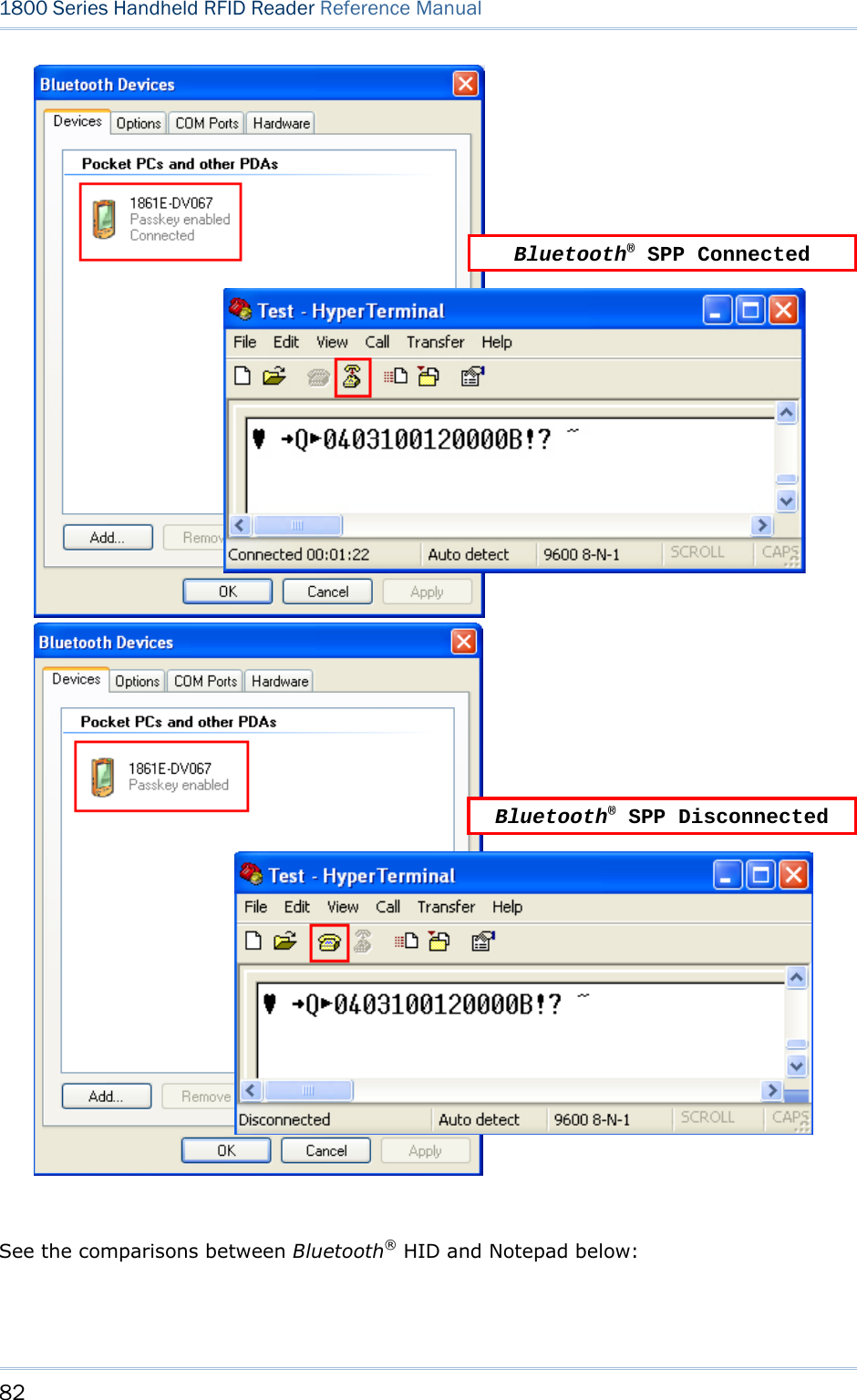
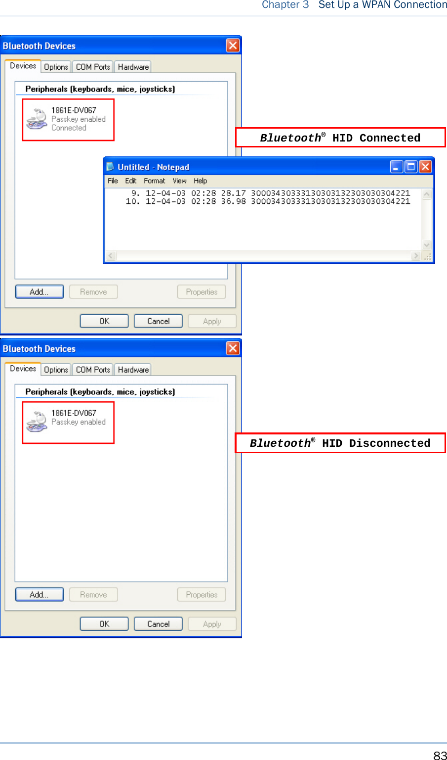
![75 Chapter 3 Set Up a WPAN Connection Note: When using Bluetooth® HID, some device driver may not support pre-defined PIN code for authentication. In this case, make sure you have RFID Reader set to “No PIN or use random PIN” before pairing. While pairing, the host PIN code will be displayed on the host computer. Have RFID Reader to input the matching PIN code for connection. Refer to 1.4.3 Bluetooth® Pairing Mode. Bluetooth Simple Security Pairing Mode Command: #@bt_ssp?\r Purpose Get Bluetooth® Parameter Response OK,[m]\r [m]:SSP Mode ‘0’ – Didable ‘1’ – Enable (Default) ERR, [code]\r #@bt_ssp=[m]\r Purpose Set Bluetooth® Parameter Response OK\r ERR,[code]\r Note: SSP feature is only for iOS currently. 3.1.3 BLUETOOTH® HID AND SPP SLAVE The procedure goes through associating devices for establishing a WPAN connection, which is pretty much the same except for the software you are using. If your computer is running Microsoft® Windows® XP (SP1 to SP3), Windows Vista® Service Pack 1 (SP1) and Windows 7, you can use the software support that Windows® includes, or you can use the driver that the device manufacturer provides. Now, let’s try using the software support that Windows® XP Service Pack 2 includes. BLUETOOTH® HID By default, the keyboard type of Bluetooth® HID is set to PCAT (US). When Bluetooth® HID is re-activated, you have to select a keyboard type to complete this setting. Refer to 2.3.1 Activate Bluetooth® HID & Select Keyboard Type.](https://usermanual.wiki/CipherLab/1861/User-Guide-1740510-Page-87.png)
![76 1800 Series Handheld RFID Reader Reference Manual Refer to steps 1~11 below for a Bluetooth® connection. BLUETOOTH® SPP SLAVE 1) Enable the Bluetooth® function on host computer. (Windows® XP only) 2) Double-click the Bluetooth® icon located on the lower right of the taskbar. Alternatively, you may go to Control Panel > Bluetooth Devices. 3) Click [Add] to search devices nearby. 4) Turn on RFID Reader with correct WPAN settings, such as select Bluetooth® SPP Slave or HID, broadcasting enabled, authentication enabled, and PIN code specified, etc if you want to use a passkey. Select “My device is set up and ready to be found” check box on the “Add Bluetooth® Device Wizard” window. 5) Click [Next].](https://usermanual.wiki/CipherLab/1861/User-Guide-1740510-Page-88.png)
![77 Chapter 3 Set Up a WPAN Connection 6) Wait for a few seconds for the Wizard to search available devices nearby. All available devices will appear on the search window. Select the device (e.g. RFID Reader) that you want to connect. If the target device does not appear on the list, click [Search Again] to refresh the list. The RFID Reader might enter power-saving mode during an idling time (=discoverable), and you can press the <Trigger> to have it active again. It will then stay active for a specified period of time (2 minutes by default) and wait for the host computer to establish a connection. 7) See SPP Slave connection below, click [Next].](https://usermanual.wiki/CipherLab/1861/User-Guide-1740510-Page-89.png)
![78 1800 Series Handheld RFID Reader Reference Manual See BT HID connection below, click [Next]. 8) Enter the passkey for authentication, which must be exactly the same as configured for RFID Reader. Click [Next].](https://usermanual.wiki/CipherLab/1861/User-Guide-1740510-Page-90.png)
![79 Chapter 3 Set Up a WPAN Connection 9) Wait for a few seconds for Windows to confirm the Passkey. 10) See SPP Slave connection below, click [Finish].](https://usermanual.wiki/CipherLab/1861/User-Guide-1740510-Page-91.png)
![80 1800 Series Handheld RFID Reader Reference Manual See BT HID connection below, click [Finish]. Note: When Bluetooth® security is enabled without providing a pre-set PIN code, the random of PIN code is supported. RFID Reader as Bluetooth® SPP Slave](https://usermanual.wiki/CipherLab/1861/User-Guide-1740510-Page-92.png)
![84 1800 Series Handheld RFID Reader Reference Manual 3.1.4 BLUETOOTH® SPP MASTER BLUETOOTH® SPP MASTER 1) Enable the Bluetooth® function on the host computer. 2) Double-click the Bluetooth® icon located on the lower right of the taskbar. Alternatively, you may go to Control Panel > Bluetooth Devices. 3) Select Hardware tab and click [Properties]. 4) In the Generic Bluetooth® Radio Properties window, select Advanced tab to see the Bluetooth® MACID of host computer.](https://usermanual.wiki/CipherLab/1861/User-Guide-1740510-Page-96.png)
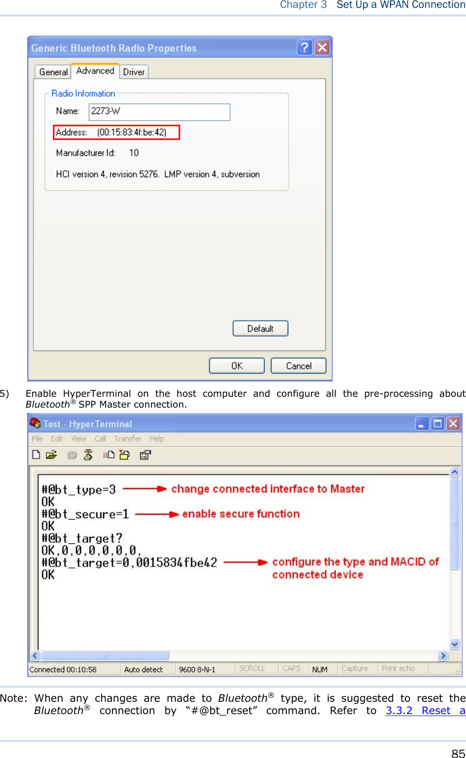
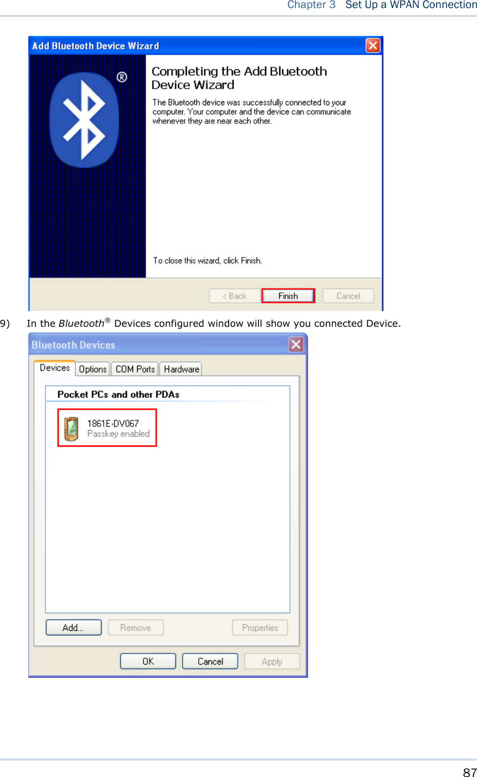
![86 1800 Series Handheld RFID Reader Reference Manual Connection. 6) On the host computer, a Bluetooth® connection information box will pop-up on the lower right of the taskbar. Click it. 7) In the Add Bluetooth® Device Wizard window, key in the passkey that is the same as you have entered on the RFID Reader. The default value is 0000. Click [Next]. 8) Click [Finish].](https://usermanual.wiki/CipherLab/1861/User-Guide-1740510-Page-98.png)
![92 1800 Series Handheld RFID Reader Reference Manual 3.3 DISCONNECTION You can break a connection between RFID Reader and host computer by pressing <F1> + <F2> directly to shut down the RFID Reader. Or issue commands described as below sections to make a disconnection. By default, it is set to automatically shut down after idling 10 minutes. Refer to 1.1.2 Power OFF. Note: The condition between RFID Reader and host computer will also be broken once the RFID Reader enters power saving mode. By default, it is set to idle at full-speed for 2 minutes before it enters power saving mode. Refer to 1.1.3 Power Saving Mode. 3.3.1 BREAK A CONNECTION You can force the RFID Reader to break a Bluetooth® connection with host computer by issuing command. Command: #@bt_disc\r Purpose Break Current Bluetooth® Connection Response OK\r ERR,[code]\r 3.3.2 RESET A CONNECTION For Bluetooth® connection, you can only have the RFID Reader connected to one computer at a time. If you want to connect the RFID Reader to another host computer, you have to issue “#@bt_reset” command to break the current connection. Simultaneously all of previous records will also be cleared. Then, the RFID Reader will restart itself automatically. Go through the whole process in Set Up a WPAN Connection to establish a new connection. Command: #@bt_reset\r Purpose Reset Bluetooth® Connection Response OK\r ERR,[code]\r Warning: Once resetting Bluetooth® connection, it will the same as entering power saving mode, the Bluetooth® will be disconnected. 3.4 BLUETOOTH® POWER SAVING](https://usermanual.wiki/CipherLab/1861/User-Guide-1740510-Page-104.png)
![93 Chapter 3 Set Up a WPAN Connection Once the Bluetooth® is connected upon no data transmitted, The RFID Reader will have LED2 flashing blue to wait data transmitting. Once enabling the Bluetooth® power saving function, Bluetooth® connection will be disconnected and the LED2 will go off. Press the <Trigger> to wake up the RFID Reader and make the Bluetooth® connection go back to standby mode with LED2 flashing. Command: POWER SAVING By default, this feature is enabled, meaning the RFID Reader will listen to the wireless network at a reduced rate. Command: #@bt_ps?\r Purpose Get Bluetooth® Power Saving Response OK,[m]\r (Default m= ‘1’) [m]: Power Saving ‘0’ – Disable ‘1’ – Enable ERR,[code]\r #@bt_ps=[m]\r Purpose Set Bluetooth® Power Saving Response OK\r ERR,[code]\r Note: When connecting more than two devices to a notebook computer with Bluetooth® wireless technology, we suggest that you disable the Bluetooth® Power Saving function for a more reliable connection.](https://usermanual.wiki/CipherLab/1861/User-Guide-1740510-Page-105.png)
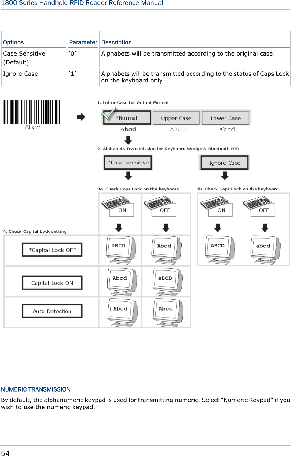
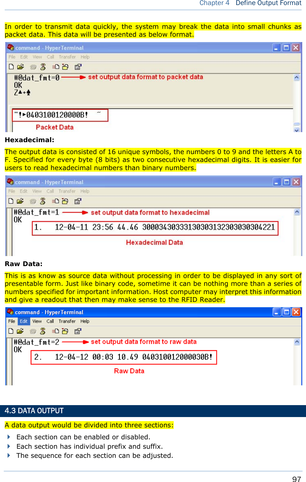
![96 1800 Series Handheld RFID Reader Reference Manual 4.1 LETTER CASE (HID MODE ONLY) By default, the alphabetic transmission is case-sensitive, meaning that the alphabet will be transmitted according to their original case. Ignoring the original letter case, select [Upper Case] to output data in upper case only; otherwise, select [Lower Case] to output data in lower case only. Refer to 2.3.1 Activate Bluetooth® HID & Select Keyboard Type or 2.6.1 Activate USB HID & Select Keyboard Type. 4.2 OUTPUT FORMAT You have to define the output data format firstly before capturing the data transmission from RFID Reader. There are three output formats specified to various Bluetooth® interface. BT SPP/USB VCOM via 3610 The output formats for Bluetooth® SPP/USB VCOM via 3610 are specified to Packet Data, Hexadecimal and Raw Data. The default value is Packet Data. BT HID/USB HID via 3610 The output formats for Bluetooth® HID/USB HID via 3610 are specified to Hexadecimal and Raw Data. The default value is Hexadecimal. Note: Bluetooth® HID or USB HID via 3610 interface does not support Packet Data as an output format. Command: #@dat_fmt?\r Purpose Get Current Output Data Format Response OK,[m]\r (Default m= ‘0’) [m]: Output Data Format [m] BT SPP / USB VCOM via 3610 BT HID / USB HID via 3610 ‘0’ Packet Data Hexadecimal ‘1’ Hexadecimal ‘2’ Raw Data Raw Data ERR,[code]\r #@dat_fmt=[m]\r Purpose Set New Output Data Format Response OK\r ERR,[code]\r Example: Packet Data:](https://usermanual.wiki/CipherLab/1861/User-Guide-1740510-Page-108.png)
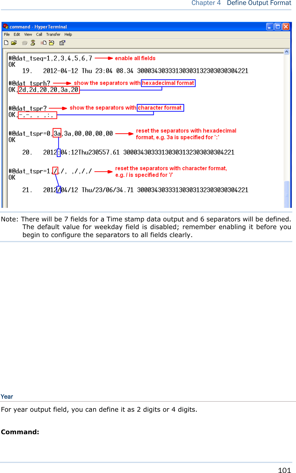
![98 1800 Series Handheld RFID Reader Reference Manual 4.3.1 TIME STAMP SECTION You can specify individual field to each section. Time Stamp section is divided into 7 fields as year, month, day, weekday, hour, minute and second. Separators can be defined among fields to make more clear presentation. It is up to 6 separators can be specified to Time Stamp section. Time Stamp Sequence Issue “#@dat_tseq=” command to configure the fields of Time Stamp section. You can set the parameter to ‘0’ to disable the field. Command: #@dat_tseq?\r Purpose Get the Sequence Settings of Time Stamp Section Response OK,[m],[n],[o],[p],[q],[r],[s]\r (Default m= ‘1’, n= ‘2’’, o= ‘3’, p= ‘0’, q= ‘5’, r= ‘6’, s= ‘7’) [m]: Time Data Type in Field 1 [n]: Time Data Type in Field 2 [o]: Time Data Type in Field 3 [p]: Time Data Type in Field 4 [q]: Time Data Type in Field 5 [r]: Time Data Type in Field 6 [s]: Time Data Type in Field 7 [m]~[s] Field ‘0’ Disable this Field ‘1’ Year ‘2’ month ‘3’ day ‘4’ weekday ‘5’ Hour ‘6’ Minute ‘7’ second ERR,[code]\r #@dat_tseq=[m],[n],[o],[p],[q],[r],[s]\r Purpose Set the Sequences of Field in Time Stamp Section Response OK\r [m]: Time Data Type in Field 1. Default = ‘1’ [n]: Time Data Type in Field 2. Default = ‘2’ [o]: Time Data Type in Field 3. Default = ‘3’ [p]: Time Data Type in Field 4. Default = ‘0’](https://usermanual.wiki/CipherLab/1861/User-Guide-1740510-Page-110.png)
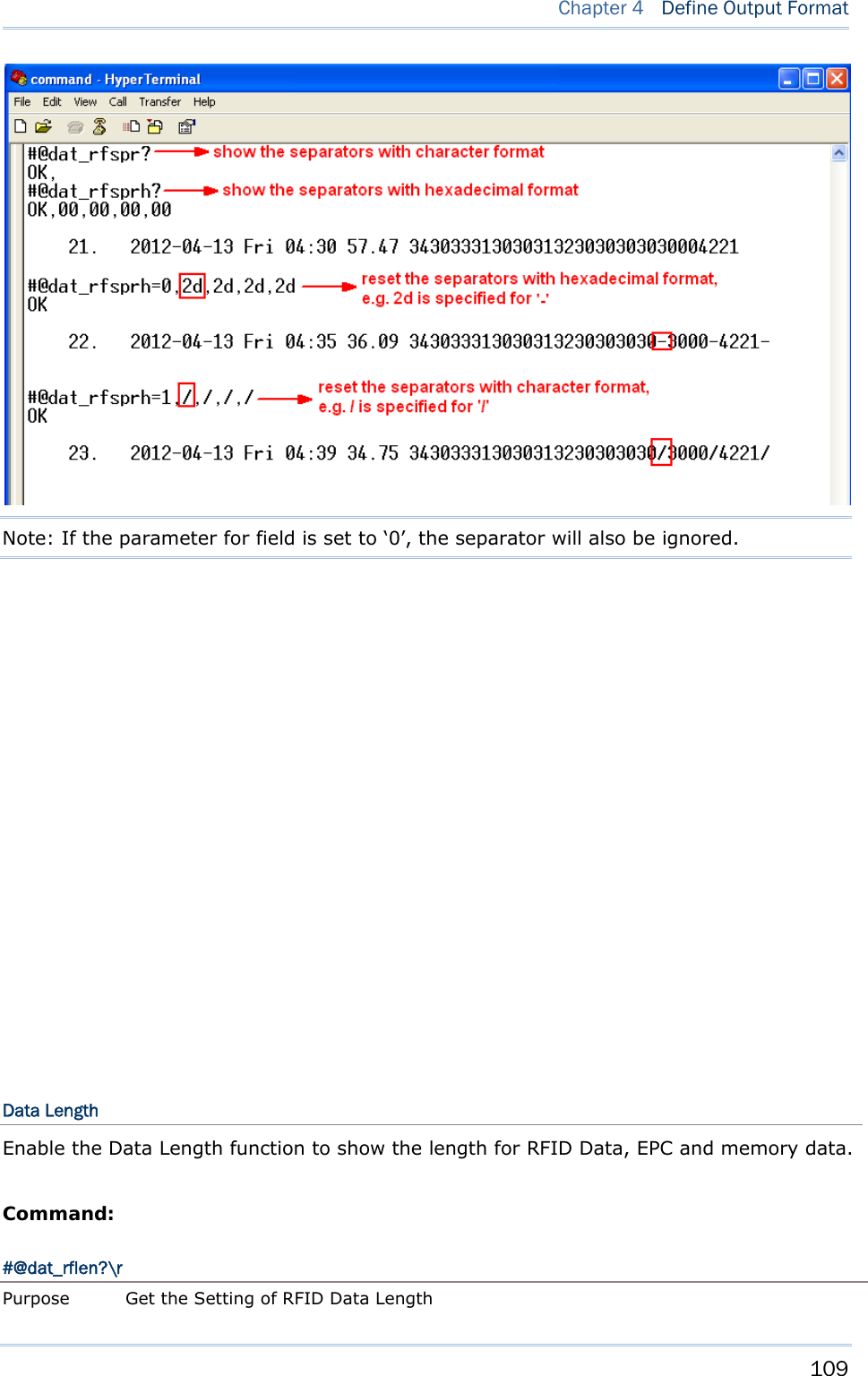
![99 Chapter 4 Define Output Format [q]: Time Data Type in Field 5. Default = ‘5’ [r]: Time Data Type in Field 6. Default = ‘6’ [s]: Time Data Type in Field 7. Default = ‘7’ ERR,[code]\r Example: Note: If the parameter for field is set to ‘0’, the separator will also be ignored. Time Stamp Separators You can configure the separator between field and field with hexadecimal or character. Refer to ASCII Table. Command: #@dat_tsprh?\r, #@dat_tspr?\r Purpose Get the Separators of Field in Time Stamp Section Request #@dat_tsprh?\r //Response data will be shown in Hexadecimal value. #@dat_tspr?\r //Response data will be shown in character. Response OK,[m],[n],[o],[p],[q],[r]\r [m]: separator between field1 and field2. Default= ‘2D’ (‘-’) [n]: separator between field2 and field3. Default= ‘2D’ (‘-’) [o]: separator between field3 and field4. Default= ‘20’ (‘ ’)](https://usermanual.wiki/CipherLab/1861/User-Guide-1740510-Page-111.png)
![100 1800 Series Handheld RFID Reader Reference Manual [p]: separator between field4 and field5. Default= ‘20’ (‘ ’) [q]: separator between field5 and field6. Default= ‘3A’ (‘:’) [r]: separator between field6 and field7. Default= ‘20’ (‘ ’) ERR,[code]\r #@dat_tspr=[m],[n],[o],[p],[q],[r],[s]\r Purpose Set the Separators of Field in Time Stamp Section Request #@dat_tspr=[m],[n],[o],[p],[q],[r],[s]\r [m]: input data format, ‘0’- in Hexadecimal, ‘1’- in character [n]: separator between field1 and field2 [o]: separator between field2 and field3 [p]: separator between field3 and field4 [q]: separator between field4 and field5 [r]: separator between field5 and field6 [s]: separator between field6 and field7 Response OK\r ERR,[code]\r Note: Input ‘00’ (hexadecimal) to clear the inputted data. Example:](https://usermanual.wiki/CipherLab/1861/User-Guide-1740510-Page-112.png)
![102 1800 Series Handheld RFID Reader Reference Manual #@dat_tyear?\r Purpose Get the Setting of Year Field Response OK,[m]\r (Default m= ‘0’.) [m]: Year format. 0 – 2 digits, 1 – 4 digits (shown as ‘20xx’). ERR,[code]\r #@dat_tyear=[m]\r Purpose Set the Year Field Response OK\r [m]: Year format. m= ‘0’ is for 2 digits, m= ‘1’ is for 4 digits (shown as ‘20xx’). ERR,[code]\r Example: Millisecond Enable this function to active millisecond field. Command: #@dat_tms?\r Purpose Get the Setting of Millisecond Response OK,[m]\r (Default m= ‘1’) [m]: Show millisecond in second field. 0 – Disable, 1 – Enable](https://usermanual.wiki/CipherLab/1861/User-Guide-1740510-Page-114.png)
![103 Chapter 4 Define Output Format ERR,[code]\r #@dat_tms=[m]\r Purpose Set to Display Millisecond Response OK\r ERR,[code]\r Example: 4.3.2 DATA COUNT SECTION Define a serial number to output data. The serial number would be specified into 6 digits beginning from 000001. When the counter is up to 999999, it will be renewed from 000001. Reset Counter Event There are three events supported to reset the counter. When the parameter is ‘1’, the output data will be counted from the beginning for each event happen. Command: #@dat_rstcnt?\r Purpose Get the Setting of Reset Counter Event Response OK,[m],[n],[o]\r (Default m= ‘0’, n= ‘0’, o= ‘1’) Reset Event Enable Disable](https://usermanual.wiki/CipherLab/1861/User-Guide-1740510-Page-115.png)
![104 1800 Series Handheld RFID Reader Reference Manual [m] Get Reset Counter Command ‘1’ ‘0’ [n] UHF Power On ‘1’ ‘0’ [o] New Bluetooth® connection ‘1’ ‘0’ ERR,[code]\r #@dat_rstcnt=[m],[n.],[o]\r Purpose Set Counter Reset Event Response OK\r ERR,[code]\r #@dat_rstcnt\r Purpose Reset Data Counter Response OK\r ERR,[code]\r Note: Data Counter will always be reset when system power up. Example: Counter Padding You can define the padded character as a prefixed counter. Characters to be padded before data counter, shown in Hexadecimal value. Refer to ASCII Table. The default value is 0x20](https://usermanual.wiki/CipherLab/1861/User-Guide-1740510-Page-116.png)
![105 Chapter 4 Define Output Format (space) for 20. Command: #@dat_cntpad?\r Purpose Get the Setting of Pad Counter Character Response OK,[m]\r (Default m= ‘20’ - 0x20 space) [m]: Character to be padded before data counter, shown in Hexadecimal value. ERR,[code]\r #@dat_cntpad=[m]\r Purpose Set the Character to be Padded before Counter Response OK\r ERR,[code]\r Example:](https://usermanual.wiki/CipherLab/1861/User-Guide-1740510-Page-117.png)
![106 1800 Series Handheld RFID Reader Reference Manual 4.3.3 DATA SECTION Data section is divided into 5 fields as CRC, PC, EPC, Memory Data and Data Length. Separators can be defined among fields to make more clear presentation. It is up to 4 separators can be specified to Data section. Data Sequence By default, data sequence is PC, EPC, CRC, Memory Data and Data Length. Just because the Data Length parameter is set to ‘0’, it will not be appeared during data output. Command: #@dat_rfseq?\r Purpose Get the Sequence Setting of RFID Data Section Response OK,[m],[n],[o],[p],[q]\r (Default m= ‘2’, n= ‘3’, o= ‘1’, p= ‘4’, q= ‘0’) [m]: RFID Data in Field 1 [n]: RFID Data in Field 2 [o]: RFID Data in Field 3 [p]: RFID Data in Field 4 [q]: RFID Data in Field 5 [m]~[q] Description ‘0’ Disable this Field ‘1’ CRC ‘2’ PC ‘3’ EPC ‘4’ Memory Data This field only appears when RFID function is set to “Read Tag Memory” ‘5’ Data Length ERR,[code]\r #@dat_rfseq=[m],[n],[o],[p],[q]\r](https://usermanual.wiki/CipherLab/1861/User-Guide-1740510-Page-118.png)
![107 Chapter 4 Define Output Format Purpose Set the Sequence of Each Field in RFID Section Response OK\r ERR,[code]\r Example:](https://usermanual.wiki/CipherLab/1861/User-Guide-1740510-Page-119.png)
![108 1800 Series Handheld RFID Reader Reference Manual Data Separators You can configure the separator between field and field with hexadecimal or character. Refer to ASCII Table. Command: #@dat_rfsprh?\r, #@dat_rfspr?\r Purpose Get the Separators of Each field in RFID Data Section Request #@dat_rfsprh?\r //Response data will be shown in Hexadecimal value #@dat_rfspr?\r //Response data will be shown in character Response OK,[m],[n],[o],[p]\r (Default m= ‘00’, n= ‘00’, o= ‘00’, p= ‘00’, ‘00’ is for NULL) [m]: separator between field1 and field2 [n]: separator between field2 and field3 [o]: separator between field3 and field4 [p]: separator between field4 and field5 ERR,[code]\r #@dat_rfspr=[m],[n],[o],[p],[q]\r Purpose Set the Separators of Each field in RFID Data Section Response OK\r ERR,[code]\r If field n (n=1~4) is disabled, separator n is also ignored. Note: Input ‘00’ (hexadecimal) to clear the inputted data. Example:](https://usermanual.wiki/CipherLab/1861/User-Guide-1740510-Page-120.png)
![110 1800 Series Handheld RFID Reader Reference Manual Response OK,[m]\r (Default m= ‘0’) [m]: Data Length Type ‘0’- Total RFID Data Length. Separators are not included. ‘1’- EPC Length ‘2’- Memory Data Length ERR,[code]\r #@dat_rflen=[m]\r Purpose Set the RFID Data Length Response OK\r ERR,[code]\r Example: 4.4 PREFIX/SUFFIX CODE By default, there is no prefix code configured to Counter and RFID Data Section, and [ENTER] or [CR] (Carriage Return) is configured to be suffix code for RFID Data Section. Up to 8 characters can be configured, for example, “Tag_Test”, and you will have the string appeared in front of the tag read, like this – “Tag_Test300034303331 30303132303030304221”. If the specified content is longer than 8 bytes, it will be truncated. Prefix/Suffix Section For a prefix or suffix parameter, you have to specify for which one section (e.g. Data](https://usermanual.wiki/CipherLab/1861/User-Guide-1740510-Page-122.png)
![111 Chapter 4 Define Output Format Counter, Time Stamp or RFID Data) you want to define firstly. Command: #@dat_pfxidx?\r Purpose Get Prefix/Suffix Parameter Response OK,[m]\r [m]: Prefix / Suffix Parameter [m] Description ‘1’ Prefix of Data Counter Section ‘2’ Suffix of Data Counter Section ‘3’ Prefix of Time Stamp Section ‘4’ Suffix of time Stamp Section ‘5’ Prefix of RFID Data Section ‘6’ Suffix of RFID Data Section ERR,[code]\r #@dat_pfxidx=[m]\r Purpose Set Prefix Parameter Response OK\r ERR,[code]\r Prefix/Suffix PARAMETER Command: #@dat_pfxh?\r, #@dat_pfx?\r Purpose Get Prefix/Suffix Request #@dat_pfxh?\r //Response data will be shown in Hexadecimal value #@dat_pfx?\r //Response data will be shown in character Response OK,[m]\r [m]: input data format, ‘0’- in Hexadecimal, ‘1’- in character [n]: data to be stored in Prefix / Suffix buffer ERR,[code]\r #@dat_pfxh= [m]\r, #@dat_pfx=[n]\r](https://usermanual.wiki/CipherLab/1861/User-Guide-1740510-Page-123.png)
![112 1800 Series Handheld RFID Reader Reference Manual Purpose Set Prefix/Suffix Response OK\r ERR,[code]\r Default Prefix of Counter Section ‘00’ (NULL) Prefix of Time Stamp Section ‘20’ (SPACE) Prefix of RFID Data Section ‘00’ (NULL) Suffix of Counter Section ‘2E’ (.) Suffix of Time Stamp Section ‘20’ (SPACE) Suffix of RFID Data Section ‘0D’ (CR) Example1 (Prefix): Example2 (Suffix):](https://usermanual.wiki/CipherLab/1861/User-Guide-1740510-Page-124.png)
![113 Chapter 4 Define Output Format 4.5 SECTION SEQUENCE After finishing all section configurations, you can adjust the sequence or disable the section. Command: #@dat_seq?\r Purpose Get the Setting of Output Data Sequence Response OK,[m],[n],[o]\r (Default m= ‘1’, n= ‘2’, o= ‘3’) [m]: Section in sequence 1 [n]: Section in sequence 2 [o]: Section in sequence 3 Data section will be one of the following: [m]/[n]/[o] Section ‘0’ Disable this section ‘1’ Count section ‘2’ Time Stamp section ‘3’ RFID Data section ERR,[code]\r #@dat_seq=[m],[n],[o]\r Purpose Set Output Data Sequence](https://usermanual.wiki/CipherLab/1861/User-Guide-1740510-Page-125.png)
![114 1800 Series Handheld RFID Reader Reference Manual Response OK\r ERR,[code]\r Example:](https://usermanual.wiki/CipherLab/1861/User-Guide-1740510-Page-126.png)

![117 RFID Reader supports a switcher allows you to switch between RFID and Alternate Mode. You can get the status between RFID and Alternated mode by issuing “#@rf_switch?” command. Command: #@rf_switch?\r Purpose Get the Status between RFID and Alternate Mode Response OK,[m]\r (Default m= ‘1’) [m]: Status of RFID/EXT Switch ‘0’ – EXT Mode (Alternate Mode) ‘1’ – RFID Mode ERR,[code]\r IN THIS CHAPTER 5.1 Scan Mode ............................................................... 117 5.2 Scan Time ............................................................... 119 5.3 Filter ....................................................................... 122 5.4 Multi-Tag ................................................................. 131 5.5 Access Tag ............................................................. 134 5.1 SCAN MODE Chapter 5 RFID SCAN](https://usermanual.wiki/CipherLab/1861/User-Guide-1740510-Page-129.png)
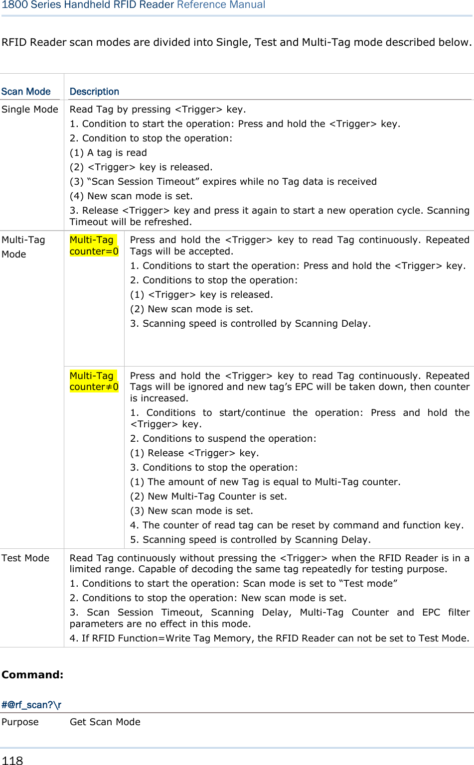
![119 Chapter 5 RFID Scan Response OK,[m]\r (Default m= ‘6’) [m]: Scan Mode ‘6’ – Single Mode ‘7’ – Test Mode ‘9’ – Multi – Tag Mode ERR,[code]\r #@rf_scan=[m]\r Purpose Set Scan Mode Response OK\r ERR,[code]\r 5.2 SCAN TIME 5.2.1 TIMEOUT You have to specify the scanning timeout interval (0~254 sec.; 0= Disable) when the scan mode is set to Single Mode. Operation will stop if the operation time = Scan Session Timeout and No Tag data is received. The range of timeout is 0~254 second. When the timeout is set to ‘0’, the operation will not stop. Command: #@rf_tscan?\r Purpose Get Scan Session Timeout Response OK,[m]\r (Default m= ‘0’)](https://usermanual.wiki/CipherLab/1861/User-Guide-1740510-Page-131.png)
![120 1800 Series Handheld RFID Reader Reference Manual [m]: Timeout, ‘0’ ~ ‘254’ ERR,[code]\r #@rf_tscan=[m]\r Purpose Set Scan Section Timeout Response OK\r ERR,[code]\r Note: This command is available for Single Mode. If you set the “#@rf_tscan” value to 5, the waiting time is over to 5 sec. upon pressing <Trigger>. And no tag data is received, the operation will stop.](https://usermanual.wiki/CipherLab/1861/User-Guide-1740510-Page-132.png)
![121 Chapter 5 RFID Scan 5.2.2 DELAY TIME You can set the RFID Reader always scanning or make an interval between each decoding. Specify the scanning delay time when the scan mode is set to Multi-Tag Mode: Command: #@rf_scandly?\r Purpose Get Scan Delay Response OK,[m]\r (Default m= ‘0’) [m]: Scan Delay ‘0’ 100ms ‘1’ 200ms ‘2’ 400ms ‘3’ 800ms ‘4’ 1 sec ‘5’ 2 sec ‘6’ 3 sec ‘7’ 5 sec ERR,[code]\r #@rf_scandly=[m]\r Purpose Set Scan Delay Response OK\r ERR,[code]\r](https://usermanual.wiki/CipherLab/1861/User-Guide-1740510-Page-133.png)
![122 1800 Series Handheld RFID Reader Reference Manual 5.3 FILTER 5.3.1 EPC ENCODING SCHEME Accepted EPC Encoding Scheme - Parameter 1 Command: #@rf_epctype1?\r Purpose Get EPC Scheme Parameter 1 Response OK,[m]\r (Default = ‘11111111’ ) [m]: EPC Scheme parameter 1. 8 character series composed by value 0 and 1 indicating the state of supported 8 EPC Schemes. ‘0’ – to deny the tag which EPC is encoded by this scheme. ‘1’ – to accept the tag which EPC is encoded by this scheme. Character EPC encoding scheme 1 (Left) GDTI96 2 GSRN96 3 DoD96S 4 SGTIN96 5 SSCC96 6 GLN96 7 GRAI96 8(Right) GIAI96 e.g. [m]=“10011000” means only to accept the tags which EPC is encoded by GDTI96, SGTIN96,SSCC96 ERR,[code]\r #@rf_epctype1=[m]\r Purpose Set EPC Scheme Parameter 1 Response OK\r ERR,[code]\r Accepted EPC Encoding Scheme - Parameter 2 Command: #@rf_epctype2?\r Purpose Get EPC Scheme Parameter 2 Response OK,[m]\r (Default = ‘11111111’ ) [m]: EPC Scheme parameter 2. 8 character series composed by value 0 and 1 indicating the state of supported EPC](https://usermanual.wiki/CipherLab/1861/User-Guide-1740510-Page-134.png)
![123 Chapter 5 RFID Scan Schemes. 0 Æto deny the tag which EPC is encoded by this scheme. 1 Æto accept the tag which EPC is encoded by this scheme. Character EPC encoding scheme 1 (Left) GID96 2 SGTIN198 3 GRAI170 4 GIAI202 5 SGLN195 6 GDTI113 7 ADI 8(Right) Reserved Always read and write as 1 ERR,[code]\r #@rf_epctype2=[m]\r Purpose Set EPC Scheme Parameter 2 Response OK\r ERR,[code]\r Note: If both EPC Scheme parameter 1 and 2 are set to “11111111”, it means with accepting all tags without checking EPC encoding schemes.](https://usermanual.wiki/CipherLab/1861/User-Guide-1740510-Page-135.png)
![124 1800 Series Handheld RFID Reader Reference Manual 5.3.2 INCLUDED EPC Filter is used in order to define a pattern of the tag where should the same as selected part of EPC. The selected part of EPC that have to fit for the requirements then can be accepted. Note: Tags that fit to the defined configurations will be accepted. Start Define the acceptable start bit of EPC that you want to filter. Command: #@rf_sepcsb?\r Purpose Get Included EPC Start Bit Response OK,[m]\r (Default m= ‘0’) [m]: Start bit of EPC. Max 255 and sum of start bit and pattern length bit cannot be more than 256. ERR,[code]\r #@rf_sepcsb=[m]\r Purpose Set Included EPC Start Bit Response OK\r ERR,[code]\r Length The Max. value is 256. Sum of star bit and pattern length bit can not be more than 256. The length must include prefix, suffix and length code, etc. A value from 0 to 256 can be specified. When zero is given, the RFID Reader will not perform the length qualification. Command: #@rf_sepcl?\r Purpose Get Included EPC Length Response OK,[m]\r (Default m= ‘0’) [m]: Pattern length bits. Max 256 and sum of start bit and pattern length bit cannot be more than 256. ERR,[code]\r #@rf_sepcl=[m]\r Purpose Set Included EPC Length Response OK\r ERR,[code]\r](https://usermanual.wiki/CipherLab/1861/User-Guide-1740510-Page-136.png)
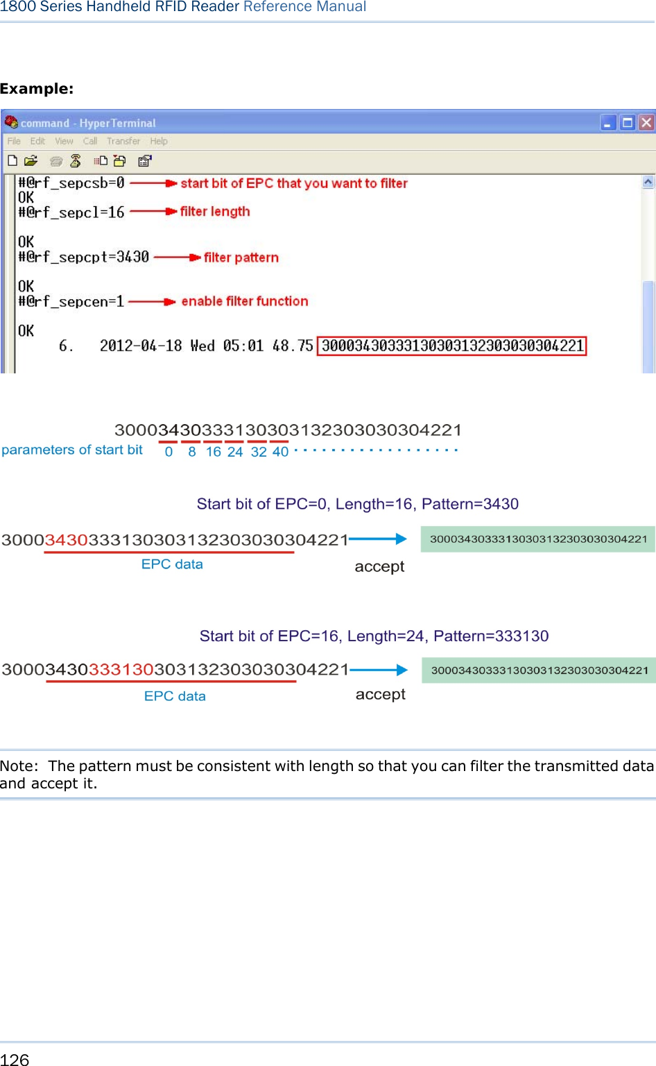
![125 Chapter 5 RFID Scan Pattern Define the hexadecimal pattern that is used to be compared. Command: #@rf_sepcpt?\r Purpose Get Included EPC Pattern Response OK,[m]\r (Default m= ‘00’) [m]: EPC pattern in hexadecimal value. ERR,[code]\r #@rf_sepcpt=[m]\r Purpose Set Included EPC Pattern Response OK\r ERR,[code]\r #@rf_sepcpt2?\r Purpose Get Included EPC2 Pattern Response OK,[m]\r (Default m= ‘00’) [m]: EPC pattern in hexadecimal value. ERR,[code]\r #@rf_sepcpt2=[m]\r Purpose Set Included EPC2 Pattern Response OK\r ERR,[code]\r State Disable or Enable Included EPC Filter function. Command: #@rf_sepcen?\r Purpose Get Included EPC State Response OK,[m]\r (Default m= ‘0’) [m]: ‘0’ – disable, ‘1’ – enable, ‘2’ – enable range filter ERR,[code]\r #@rf_sepcen=[m]\r Purpose Set Included EPC State Response OK\r ERR,[code]\r](https://usermanual.wiki/CipherLab/1861/User-Guide-1740510-Page-137.png)
![127 Chapter 5 RFID Scan 5.3.3 EXCLUDED EPC For an excluded EPC filter, it is unacceptable once the selected part of EPC is fitted for the requirements. Note: Tags that fit to the defined configurations will not be accepted. Start Define the unacceptable start bit of EPC that you want to filter. Command: #@rf_xepcsb?\r Purpose Get Excluded EPC Start Bit Response OK,[m]\r (Default m= ‘0’) [m]: Start bit of EPC. Max 255 and sum of start bit and pattern length bit cannot be more than 256. ERR,[code]\r #@rf_xepcsb=[m]\r Purpose Set Excluded EPC Start Bit Response OK\r ERR,[code]\r Length The Max. value is 256. Sum of star bit and pattern length bit can not be more than 256. The length must include prefix, suffix and length code, etc. A value from 0 to 256 can be specified. When zero is given, the RFID Reader will not perform the length qualification. Command: #@rf_xepcl?\r Purpose Get Excluded EPC Length Response OK,[m]\r (Default m= ‘0’) [m]: Pattern length bits. Max 256 and sum of start bit and pattern length bit cannot be more than 256. ERR,[code]\r #@rf_xepcl=[m]\r Purpose Set Excluded EPC Length Response OK\r](https://usermanual.wiki/CipherLab/1861/User-Guide-1740510-Page-139.png)
![128 1800 Series Handheld RFID Reader Reference Manual ERR,[code]\r Pattern Define the hexadecimal pattern that is used to be compared. Command: #@rf_xepcpt?\r Purpose Get Excluded EPC Pattern Response OK,[m]\r (Default m= ‘00’) [m]: EPC pattern in hexadecimal value ERR,[code]\r #@rf_xepcpt=[m]\r Purpose Set Excluded EPC Pattern Response OK\r ERR,[code]\r #@rf_xepcpt2?\r Purpose Get Excluded EPC2 Pattern Response OK,[m]\r (Default m= ‘00’) [m]: EPC pattern in hexadecimal value. ERR,[code]\r #@rf_xepcpt2=[m]\r Purpose Set Excluded EPC2 Pattern Response OK\r ERR,[code]\r State Disable or Enable Excluded EPC Filter function. Command: #@rf_xepcen?\r Purpose Get Excluded EPC State Response OK,[m]\r (Default m= ‘0’) [m]: ‘0’ – disable, ‘1’ – enable, ‘2’ – enable range filter ERR,[code]\r #@rf_xepcen=[m]\r Purpose Set Excluded EPC State Response OK\r](https://usermanual.wiki/CipherLab/1861/User-Guide-1740510-Page-140.png)
![129 Chapter 5 RFID Scan ERR,[code]\r Example: Note: The pattern must be consistent with length so that you can filter the transmitted data and eliminate it. 5.3.4 EPC ENCODING](https://usermanual.wiki/CipherLab/1861/User-Guide-1740510-Page-141.png)
![130 1800 Series Handheld RFID Reader Reference Manual Acted Encoding Scheme for Included/Excluded EPC Filter Command: #@rf_epcfcode?\r Purpose Get Acted Scheme for EPC Filter Response OK,[m]\r (Default=’2C’) [m]: Acted Scheme for EPC Filter* [m] EPC Encoding Scheme ‘2C’ GDTI-96(Default) ‘2D’ GSRN-96 ‘2F’ USDoD-96 ‘30’ SGTIN-96 ‘31’ SSCC-96 ‘32’ SGLN-96 ‘33’ GRAI-96 ‘34’ GIAI-96 ‘35’ GID-96 ‘36’ SGTIN-198 ‘37’ GRAI-170 ‘38’ GIAI-202 ‘39’ SGLN-195 ‘3A’ GDTI-113 ‘3B’ ADI ERR,[code]\r #@rf_epcfcode=[m]\r Purpose Set Acted Scheme for EPC Filter Response OK\r ERR,[code]\r](https://usermanual.wiki/CipherLab/1861/User-Guide-1740510-Page-142.png)
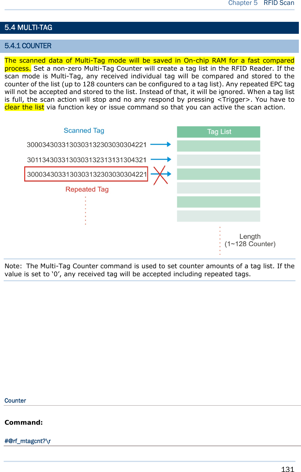
![132 1800 Series Handheld RFID Reader Reference Manual Purpose Get Multi-Tag Counter Response OK,[m]\r (Default m= ‘0’) [m]: Multi-Tag Counter, ‘0’, ‘1’ ~‘128’ ERR,[code]\r #@rf_mtagcnt=[m]\r Purpose Set Multi-Tag Counter Request #@rf_mtagcnt=[m]\r [m]: Multi-Tag Counter Response OK\r ERR,[code]\r #@rf_mtagbeep?\r Purpose Get Multi-Tag Beeping Response OK,[m],[n]\r (Default m= ‘0’, n= ‘1’) [m]: Repeated Tag Beeping is disable [n]: Tag List Full Beeping is enable ERR,[code]\r Multi-Tag List Type Command: #@rf_mtaglist?\r Purpose Get Multi-Tag List Type Response OK,[m]\r (Default m= ‘0’) [m]: Multi-Tag List Type ‘0’ – EPC ‘1’ TID ERR,[code]\r #@rf_mtaglist=[m]\r Purpose Set Multi-Tag List Type Response OK\r ERR,[code]\r 5.4.2 COUNTER RELOAD You have to clear a full tags list upon Multi-tag mode so that you can start another new scan session.](https://usermanual.wiki/CipherLab/1861/User-Guide-1740510-Page-144.png)
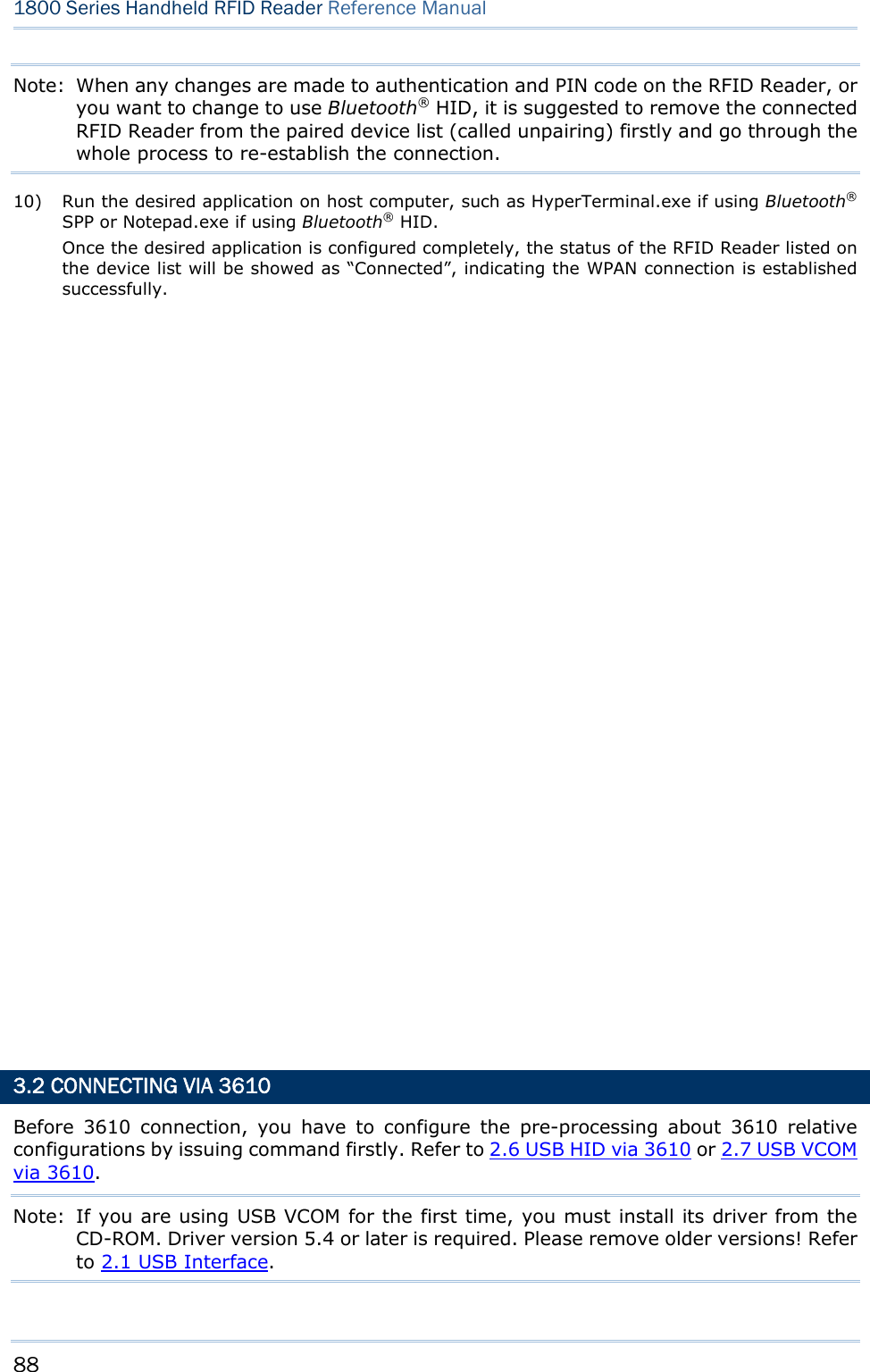
![134 1800 Series Handheld RFID Reader Reference Manual Command: #@rf_mtagbeep?\r Purpose Get Multi-Tag Beeping Response OK,[m],[n]\r (Default m= ‘0’, n= ‘1’) [m]: Repeated Tag Beeping [n]: Tag List Full Beeping ERR,[code]\r #@rf_mtagbeep=[m],[n]\r Purpose Set Multi-Tag Beeping Request #@rf_mtagbeep=[m],[n]\r [m]: Repeated Tag Beeping. ‘0’ – Disable, ‘1’ – Enable [n]: Tag List Full Beeping. ‘0’ – Disable, ‘1’ – Enable Response OK\r ERR,[code]\r 5.5 ACCESS TAG 5.5.1 TAG MEMORY A tag memory is divided into 4 banks as below:](https://usermanual.wiki/CipherLab/1861/User-Guide-1740510-Page-146.png)
![136 1800 Series Handheld RFID Reader Reference Manual 5.5.2 READ/WRITE TAG By default, the RFID Reader access mode is set to Inventory to get EPC of a tag. If you want to read all data stored in a tag, you would issue “#@rf_func=1” command that allows you to read reserved, EPC, TID or User bank. RFID Function Command: #@rf_func?\r Purpose Get RFID Function Response OK,[m]\r (Default m= ‘0’) [m]: RFID Function ‘0’ – Inventory ‘1’ – Read Tag Memory ‘2’ – Write Tag Memory ERR,[code]\r #@rf_func=[m]\r Purpose Set RFID Function Response OK\r ERR,[code]\r Access](https://usermanual.wiki/CipherLab/1861/User-Guide-1740510-Page-148.png)
![137 Chapter 5 RFID Scan Command: #@rf_rwidx?\r Purpose Get Access Parameter Response OK,[m]\r [m]: Access Parameter [m] Meaning Value Parameters ‘0’ Access Password ‘xxxxxxxx’ Access Password, 4Bytes, shown in Hexadecimal value. e.g. String ‘30313233’ indicates 0x30, 0x31, 0x32, 0x33. Default= ‘00000000’ ‘1’ Memory Bank ‘0’ – EPC ‘1’ – TID ‘2’ – User Default= ‘0’ ‘2’ Starting Address ‘0’, ‘2’, ‘4’ … ‘32’ Only even number is valid. Default= ‘0’ ‘3’ Data Length ‘0’, ‘2’, ‘4’ … ‘32’ Only even number is valid. Default= ‘0’ (Unit=byte) ERR,[code] #@rf_rwidx=[m]\r Purpose Set Access Parameter Response OK\r ERR,[code]\r #@rf_rwpr?\r Purpose Get Access Parameter Response OK,[m]\r (Default m= ‘00000000’) [m]: Access Parameter ERR,[code]\r #@rf_rwpr=[m]\r Purpose Set Access Parameter Response OK\r ERR,[code]\r Write](https://usermanual.wiki/CipherLab/1861/User-Guide-1740510-Page-149.png)
![138 1800 Series Handheld RFID Reader Reference Manual You can configure RFID Reader to write data into tag memory by issuing “#@rf=wbuf” command. Command: #@rf_wbuf?\r Purpose Get Data in Buffer Response OK,[m]\r (Default m= ‘0000’) [m]: Data in buffer. Shown in hexadecimal value [m]: Data will be stored into buffer. Buffer size = 32 Bytes Input data in hexadecimal value. The length of data must be even number. To clear the buffer, [m]= ‘0000’ e.g. ‘41’=>0x41= ‘A’ (2 Bytes NULL) The length of data must be even number. ERR,[code]\r #@rf_wbuf=[m]\r Purpose Set Data in Buffer Response OK\r ERR,[code]\r Example:](https://usermanual.wiki/CipherLab/1861/User-Guide-1740510-Page-150.png)

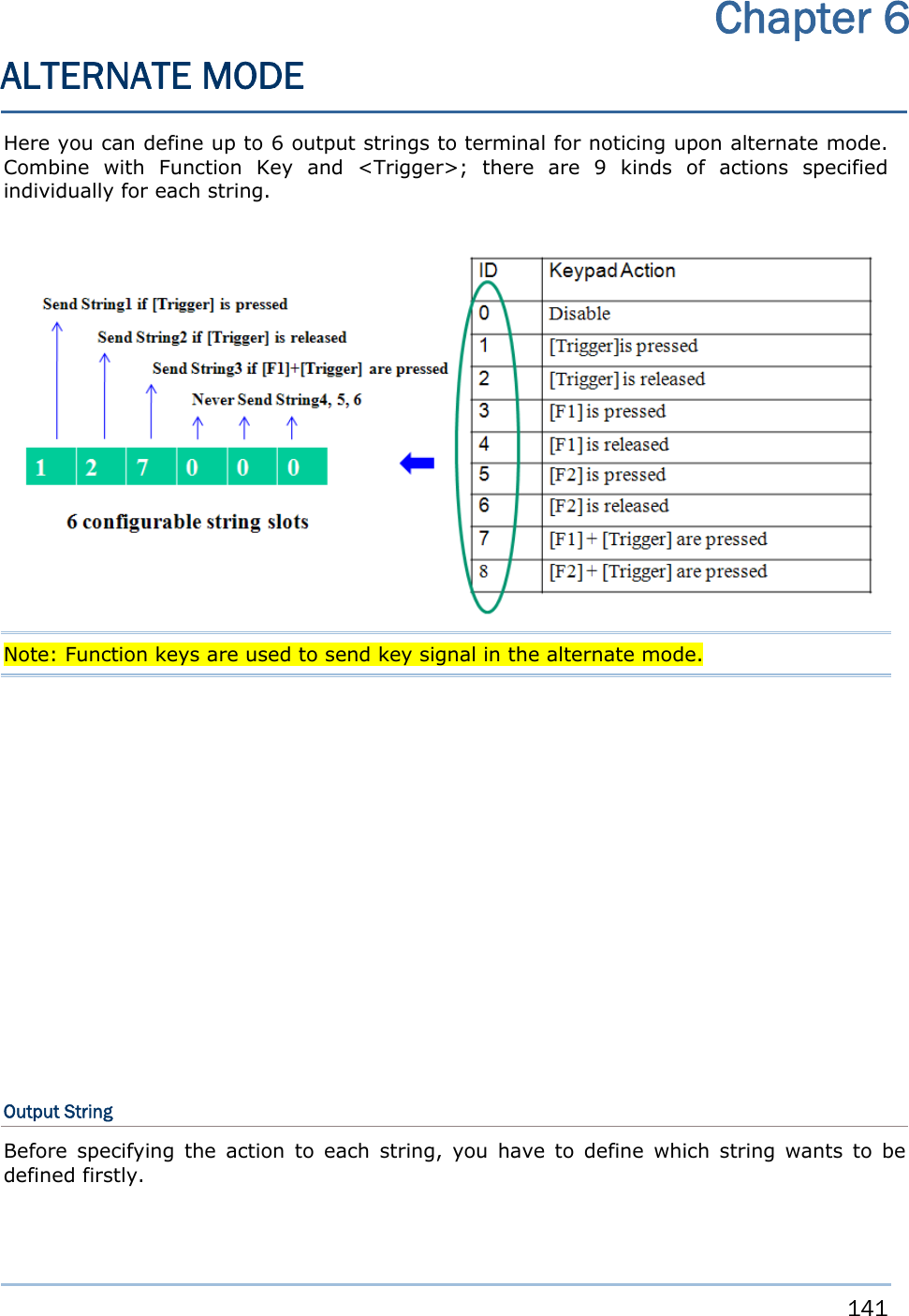
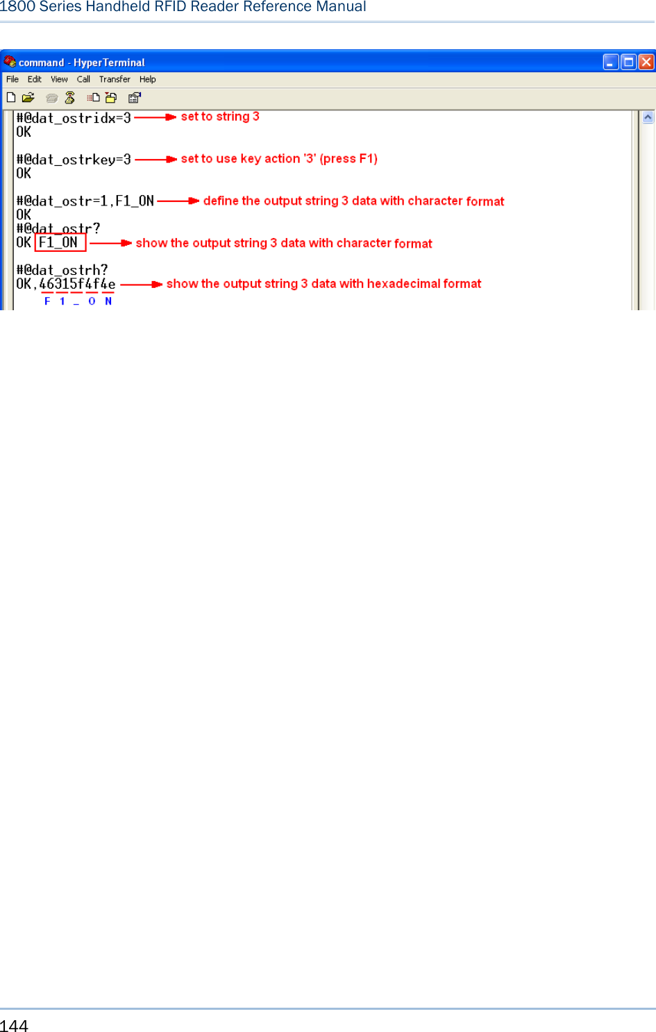
![142 1800 Series Handheld RFID Reader Reference Manual Command: #@dat_ostridx?\r Purpose Get Output String Parameter Response OK,[m]\r (Default m= ‘1’) [m]: String Buffer Parameter 1~6 ERR,[code]\r #@dat_ostridx=[m]\r Purpose Set Output String Parameter Response OK\r ERR,[code]\r Key Action Command: #@dat_ostrkey?\r Purpose Get Key Action of Output String Response OK,[m]\r (Default m= ‘1’) [m]: Key Action [m] Action ‘0’ Disable ‘1’ Trigger key is pressed ‘2’ Trigger key is released ‘3’ F1 is pressed ‘4’ F1 is released ‘5’ F2 is pressed ‘6’ F2 is released ‘7’ F1+ Trigger key are pressed ‘8’ F2 + Trigger key are pressed ERR,[code]\r #@dat_ostrkey=[m]\r Purpose Set Key Action of Output String Response OK\r ERR,[code]\r Output String Data There are two parameters will be specified here. One is the input data format – Hexadecimal or Character, another is the data that will be stored in buffer with 10 bytes. If the specified data are longer](https://usermanual.wiki/CipherLab/1861/User-Guide-1740510-Page-154.png)
![143 Chapter 6 Alternate Mode than 10 bytes, it will be truncated. Command: #@dat_ostrh?\r, #@dat_ostr?\r Purpose Get Output String Request #@dat_ostrh?\r //Response data will be shown in Hexadecimal value #@dat_ostr?\r //Response data will be shown in character Response OK,[m]\r [m]: output data format, ‘0’- in Hexadecimal, ‘1’- in character [n]: Data to be stored in buffer Data is stored in buffer. ERR,[code]\r #@dat_ostr=[m],[n]\r Purpose Set Output String Response OK\r ERR,[code]\r Default String 1 ‘#@TRIGON\r’ String 2 ‘#@TRIGOFF\r’ String 3 0x00(NULL) String 4 0x00(NULL) String 5 0x00(NULL) String 6 0x00(NULL) KEY1 ‘1’ KEY2 ‘2’ KEY3 ‘0’ KEY4 ‘0’ KEY5 ‘0’ KEY6 ‘0’ Note: Input ‘00’ (hexadecimal) to clear the inputted data. Example:](https://usermanual.wiki/CipherLab/1861/User-Guide-1740510-Page-155.png)
![149 Upgrade firmware to one RFID reader at a time. For example, turn off each of the rest RFID reader when there is more than one RFID reader connected to host computer. Note: 1. Ensure the RFID reader has a fully charged battery prior to attempting a firmware upgrade. 2. In order to avoid the data loss during firmware upgrade. Please save or upload all the data from the flash memory before beginning firmware upgrade. BEFORE UPGRADING Before firmware upgrade, you have to configure the upgrade interface with “#@sys_dlfw” command firstly. Command: #@sys_dlfw=[m]\r Purpose Load Default Setting Request #@sys_dlfw=[m]\r [m]: ‘0’ – Current interface ‘1’ – BT ‘2’ – USB Response OK\r ERR,[code]\r HOW TO UPGRADE FIRMWARE USE 3610 7) Connect 3610 to the USB port of host computer after installing its driver. 8) Refer to 3.2 Connecting via 3610 for connecting to 3610. Appendix I FIRMWARE UPGRADE](https://usermanual.wiki/CipherLab/1861/User-Guide-1740510-Page-161.png)
![150 1800 Series Handheld RFID Reader Reference Manual 9) After making a connection between 3610 and RFID Reader. Power off RFID Reader. 10) Press <F2>+<Trigger> for 3 seconds to enter Firmware Upgrade Mode with LED1 flashing red, continual beeping. 11) Run the download utility “ProgLoad.exe” on the host computer. For the communication settings, select “RS-232/IrDA” and the correct COM port for USB Virtual COM interface. Ignore the baud rate setting. For the file option, click [Browse] to select the target file e.g. U1860V*.SHX for firmware update. Click [OK]. 12) After upgrading, RFID Reader will restart automatically. USE DIRECT USB VIRTUAL COM 1) Use the provided USB cable to connect RFID Reader to the USB port of host computer. You will need to install USB cable driver firstly. 2) Refer to Using HyperTerminal for connecting with USB cable. 3) After making a connection between host computer and RFID Reader. Power off RFID Reader. 4) Press <F2>+<Trigger> for 3 seconds to enter Firmware Upgrade Mode with LED1 flashing red, continual beeping. 5) Run the download utility “ProgLoad.exe” on the host computer.](https://usermanual.wiki/CipherLab/1861/User-Guide-1740510-Page-162.png)
![151 Appendix I Firmware Upgrade For the communication settings, select “RS-232/IrDA” and the correct COM port for Direct USB Virtual COM interface. Ignore the baud rate setting. For the file option, click [Browse] to select the target file e.g. U1860V*.SHX for firmware update. Click [OK]. 6) After upgrading, RFID Reader will restart automatically. USE BLUETOOTH® DONGLE 1) Refer to 3.1.3 Bluetooth® HID and SPP Slave for the connection with Bluetooth® dongle. 2) After making a connection between Bluetooth® dongle and RFID Reader. Power off RFID Reader. 3) Press <F2>+<Trigger> for 3 seconds to enter Firmware Upgrade Mode with LED1 flashing red, continual beeping. 4) Run the download utility “ProgLoad.exe” on host computer.](https://usermanual.wiki/CipherLab/1861/User-Guide-1740510-Page-163.png)
![152 1800 Series Handheld RFID Reader Reference Manual For the communication settings, select “RS-232/IrDA” and the correct COM port for Bluetooth® SPP interface. Ignore the baud rate setting. For the file option, click [Browse] to select the target file e.g. U1860V*.SHX for firmware update. Click [OK]. 5) After upgrading, RFID Reader will restart automatically. USE <F2>+<TRIGGER> 1) Power Off RFID Reader. 2) Press and hold the <F2>+<Trigger> for 3 seconds to enter download mode. 3) Use USB cable to connect RFID Reader and host computer. 4) Run the download utility “ProgLoad.exe” on host computer to upgrade the firmware. Note: <F2>+<Trigger> firmware upgrade only supports CDC driver. Refer to 2.1 USB Interface to configure USB type. HOW TO UPGRADE 3610 FIRMWARE Connect 3610 to the USB port of host computer after installing its driver. UPGRADE 3610 CPU FIRMWARE 1) After making a connection between 3610 and RFID Reader. Power off RFID Reader. 2) Press <F2>+<Trigger> for 3 seconds to enter Firmware Upgrade Mode with LED1 flashing red, continual beeping. 3) Run the download utility “ProgLoad.exe” on the host computer.](https://usermanual.wiki/CipherLab/1861/User-Guide-1740510-Page-164.png)
![153 Appendix I Firmware Upgrade Kernel Program User Program K3610_V*.shx STD3610_V*.shx For the communication settings, select “RS-232/IrDA” and the correct COM port for USB Virtual COM interface. Ignore the baud rate setting. For the file option, click [Browse] to select the target file e.g. STD3610_V*.SHX for firmware update. Click [OK]. 4) The 3610 will automatically restart when upgrading firmware is completed successfully. UPGRADE 3610 USB BRIDGE FIRMWARE 1) After making a connection between 3610 and RFID Reader. Power off RFID Reader. 2) Press <F2>+<Trigger> for 3 seconds to enter Firmware Upgrade Mode with LED1 flashing red, continual beeping. 3) Run the download utility “ProgLoad.exe” on the host computer. Kernel Program User Program K3610Bridge_V*.shx STD3610Bridge_V*.shx](https://usermanual.wiki/CipherLab/1861/User-Guide-1740510-Page-165.png)
![154 1800 Series Handheld RFID Reader Reference Manual For the communication settings, select “RS-232” and the correct COM port for USB Virtual COM interface. Ignore the baud rate setting. For the file option, click [Browse] to select the target file for firmware update. Click [OK]. 4) The 3610 will automatically restart when upgrading firmware is completed successfully.](https://usermanual.wiki/CipherLab/1861/User-Guide-1740510-Page-166.png)
![155 0 1 2 3 4 5 6 7 0 DLE SP 0 @ P ` p 1 SOH DC1 ! 1 A Q a q 2 STX DC2 " 2 B R b r 3 ETX DC3 # 3 C S c s 4 EOT DC4 $ 4 D T d t 5 ENQ NAK % 5 E U e u 6 ACK SYN & 6 F V f v 7 BEL ETB ' 7 G W g w 8 BS CAN ( 8 H X h x 9 HT EM ) 9 I Y i y A LF SUB * : J Z j z B VT ESC + ; K [ k { C FF FS , < L \ l | D CR GS - = M ] m } E SO RS . > N ^ n ~ F SI US / ? O _ o DEL Appendix II ASCII TABLE](https://usermanual.wiki/CipherLab/1861/User-Guide-1740510-Page-167.png)