CipherLab 2564 BT Scanner User Manual
CipherLab Co., Ltd. BT Scanner
UserManual.wiki
>
CipherLab
>
2564 User Manual
User manual
Navigation menu
Upload a User Manual
Namespaces
Wiki Guide
HTML
PDF
Info
Views
User Manual
Discussion / Help
Navigation


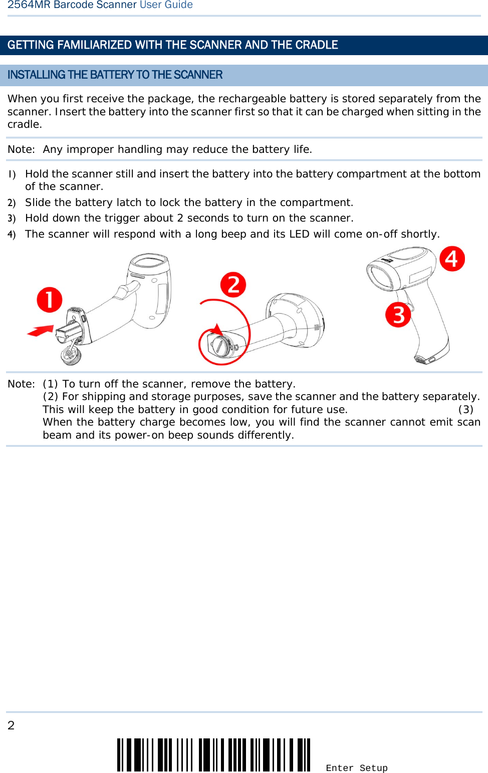
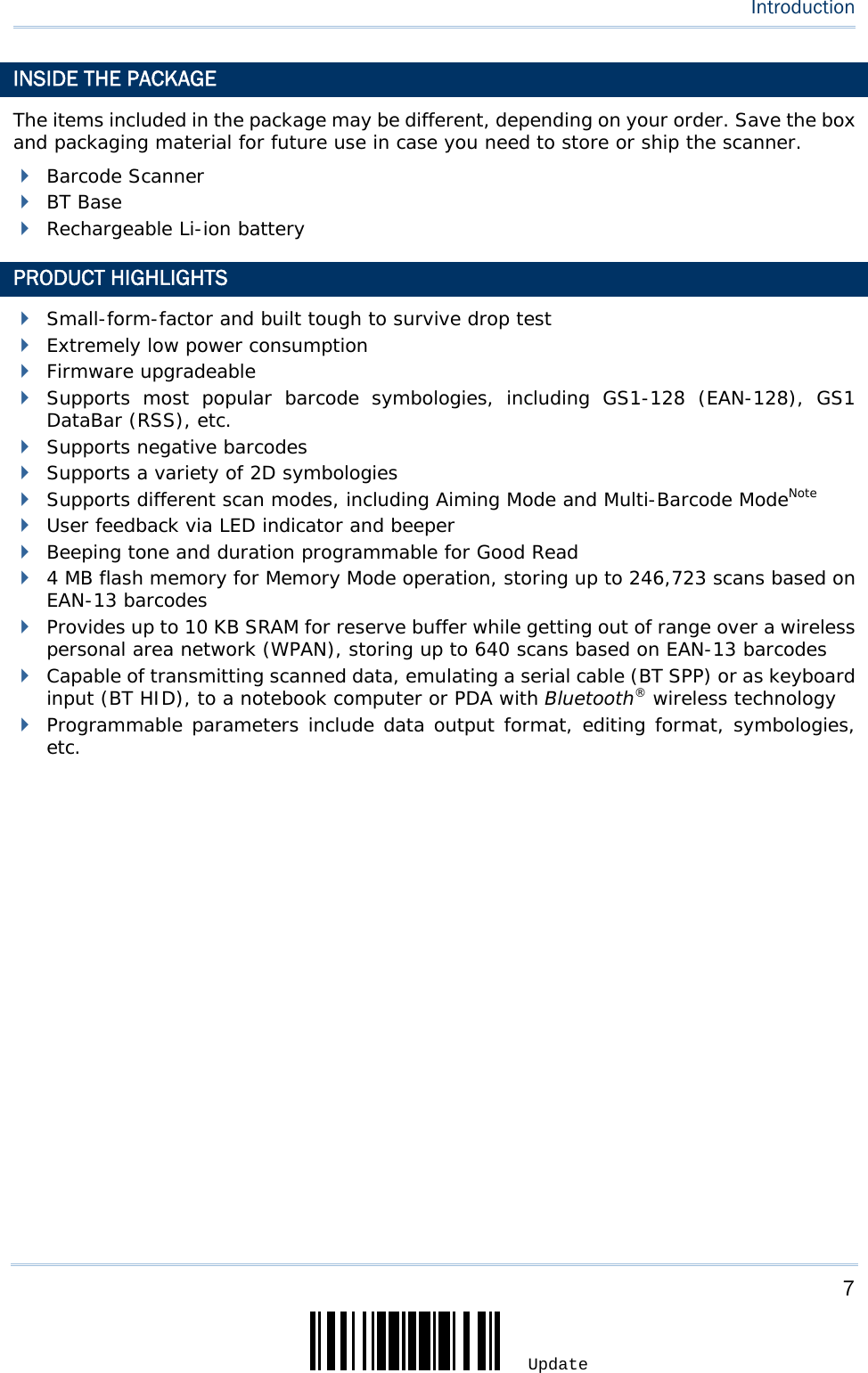
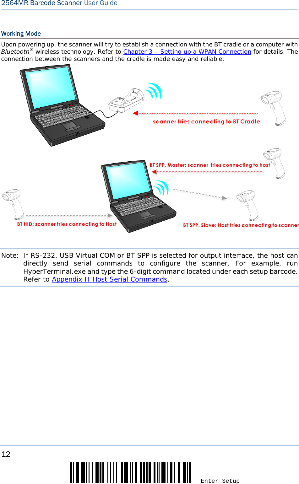
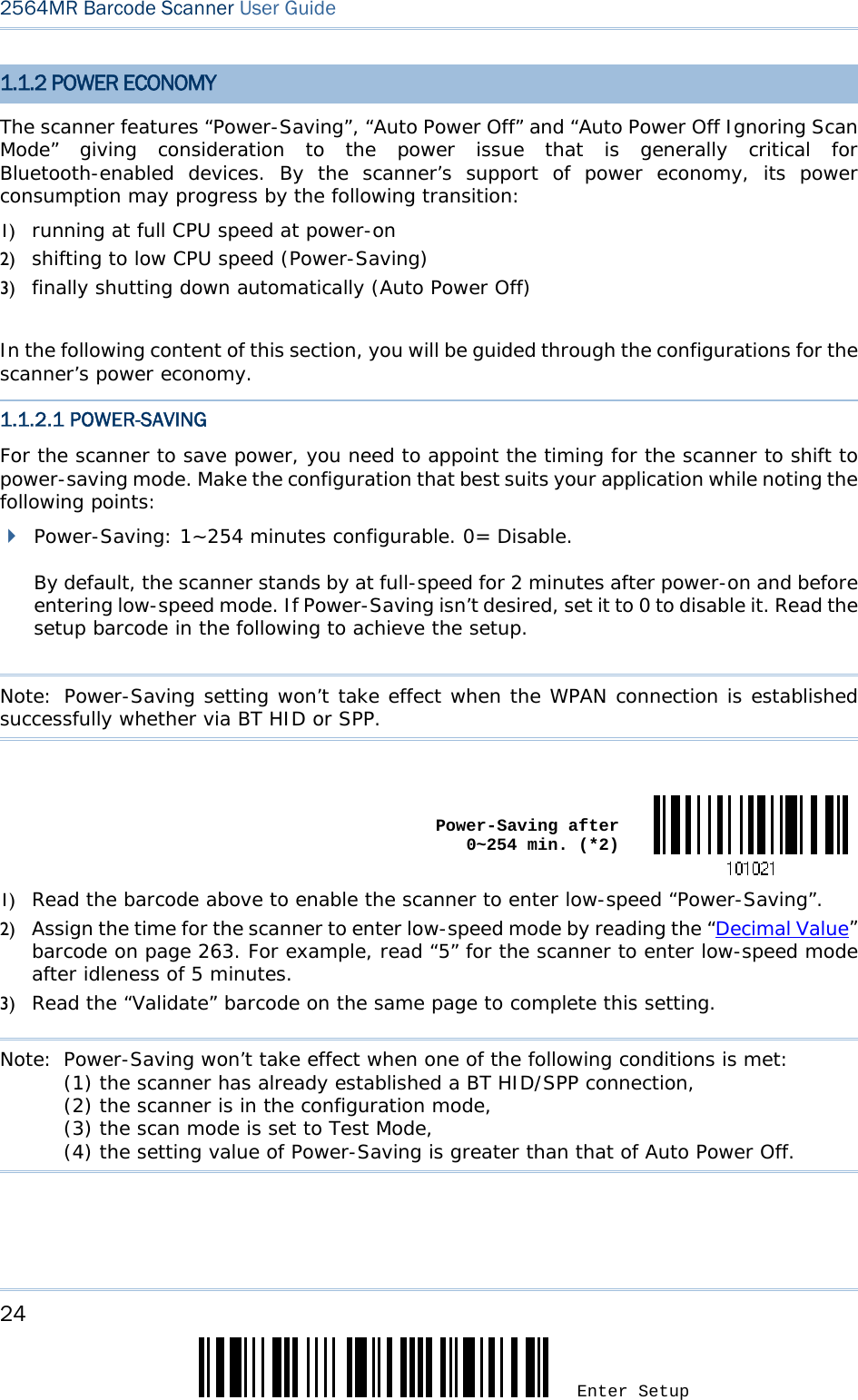
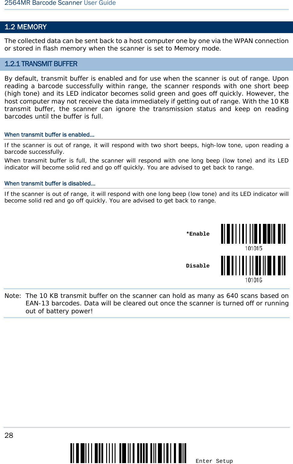
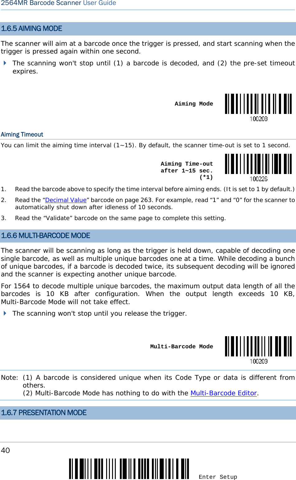
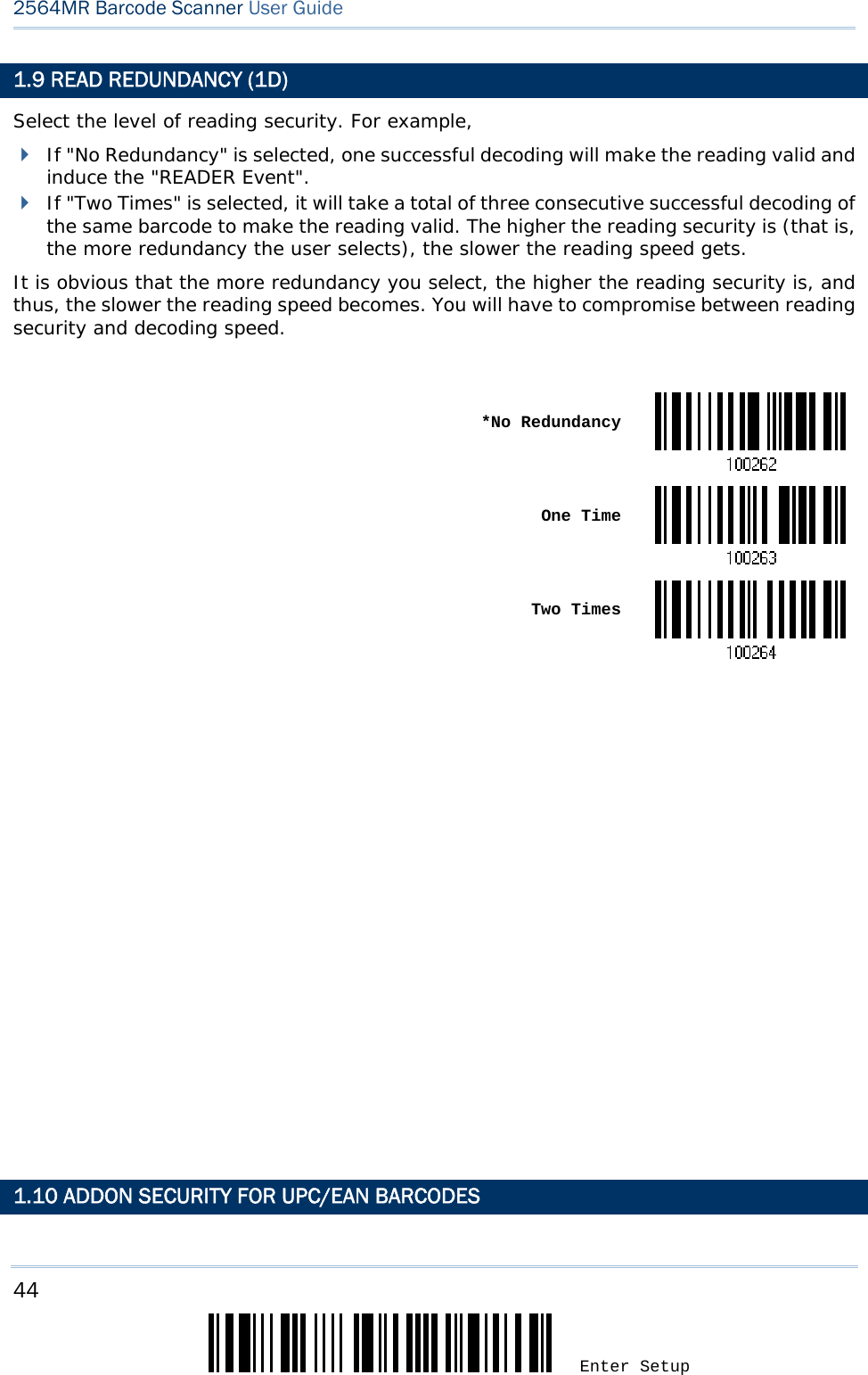
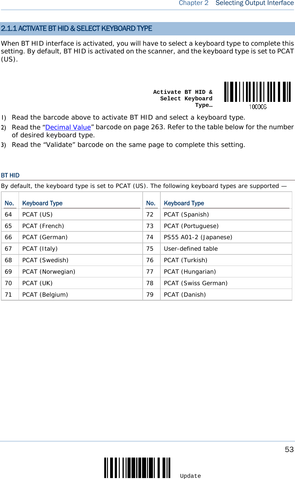
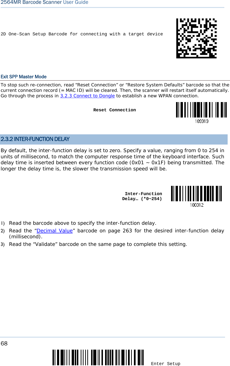
![3 Update Introduction SETTING UP THE CRADLE Capable of charging the scanner, the cradle is specifically designed for the scanner to communicate with a host computer wirelessly. Refer to 3.1.1 Connect to Cradle. Two LED indicators are provided for power and communications status. Power LED Meaning Red, solid --- Power ON --- --- Power OFF Communication LED Meaning --- Blue, solid Initialize Red, solid --- Failed to establish a USB connection Red, solid Blue, flashing Serial command mode with USB Virtual COM or RS-232: wait 3 seconds for starting a serial command Red, flashing Blue, flashing Serial command mode with USB HID: wait 3 seconds for pressing [Num Lock] or [Caps Lock] 5 times via keyboard --- Blue, flashing Wait for connection request from the scanner (Slow flash at 0.5 Hz) --- Blue, flashing Connected with the scanner (Fast flash at 1 Hz) Red, solid Blue, flashing Failed to send data to host via USB Virtual COM (Fast flash at 1 Hz)](https://usermanual.wiki/CipherLab/2564/User-Guide-3359037-Page-16.png)
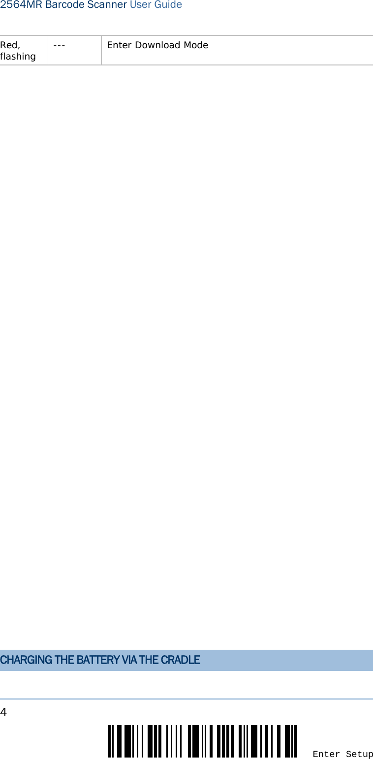
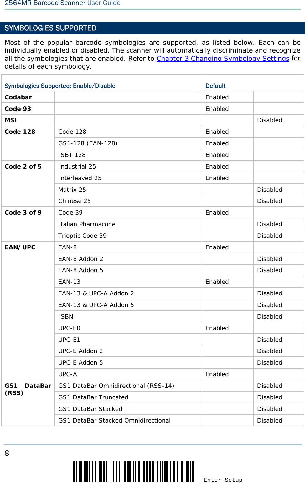
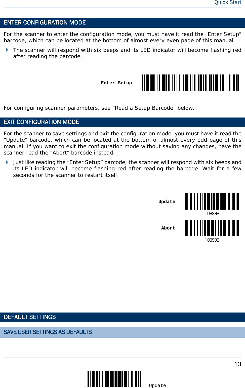
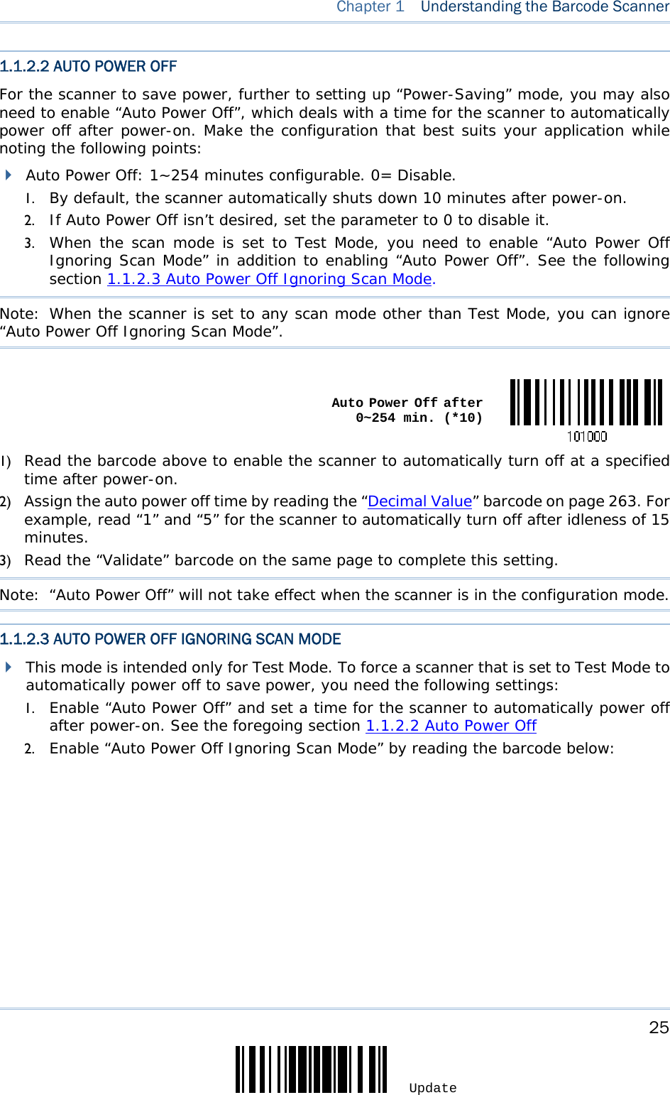
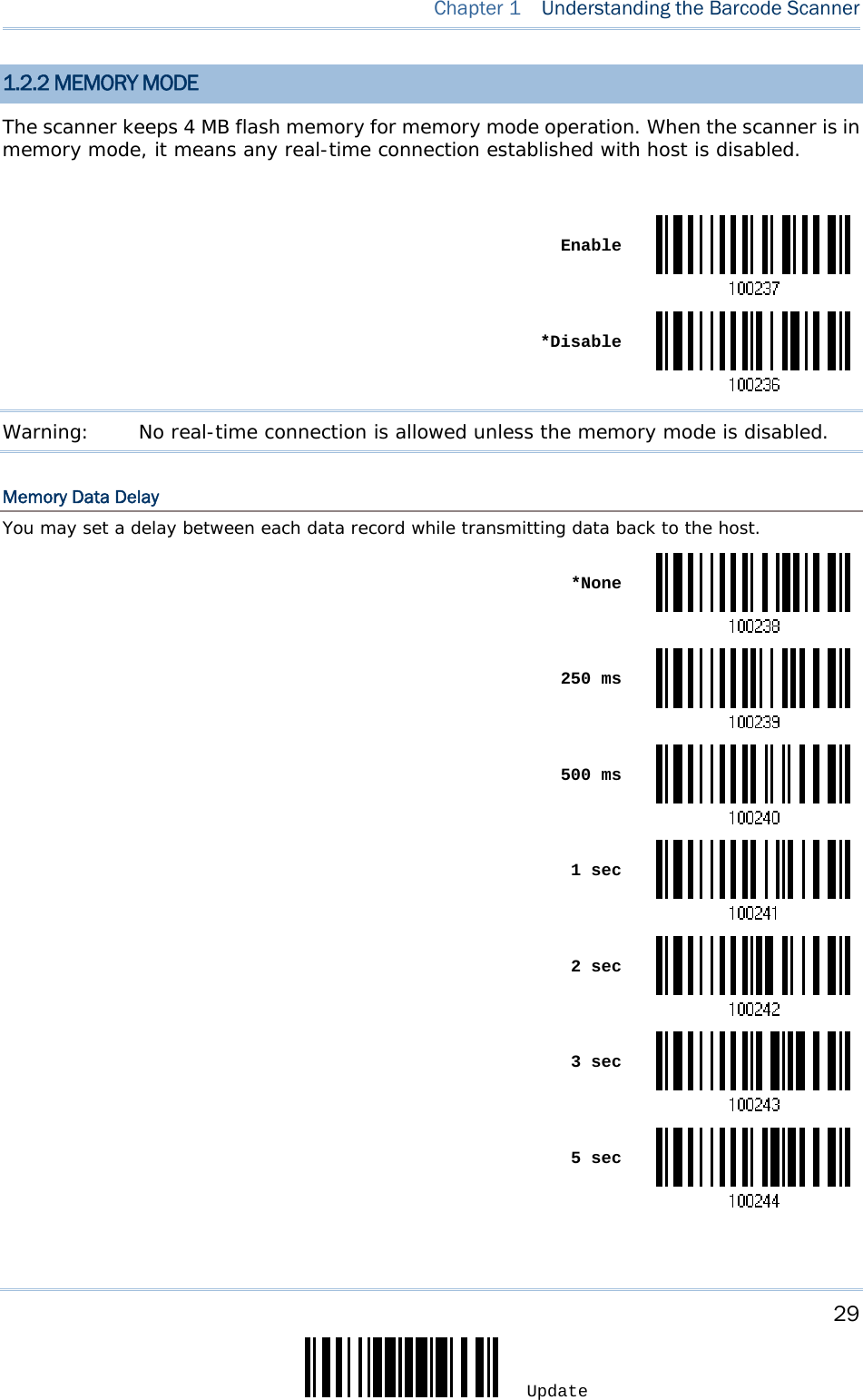
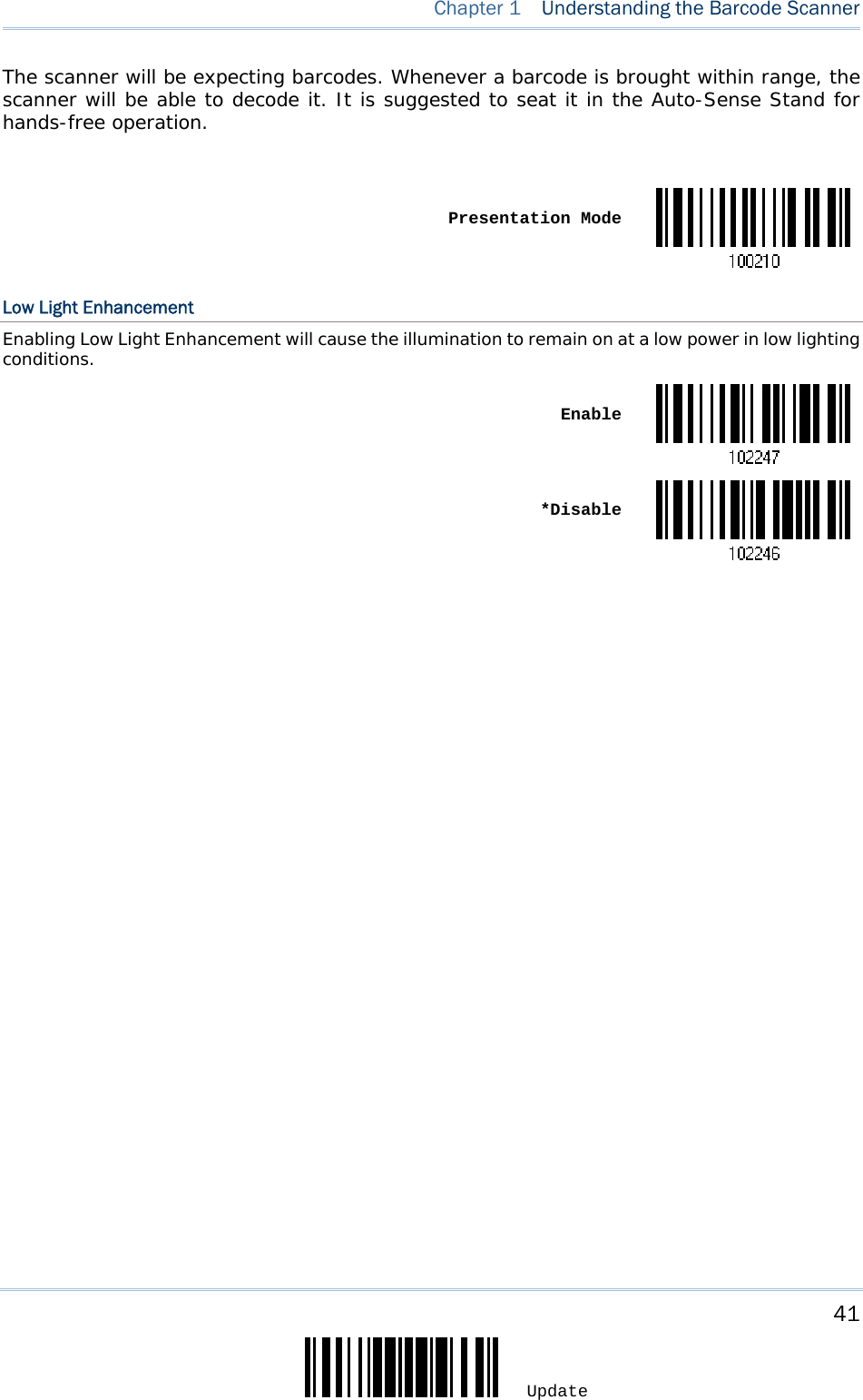
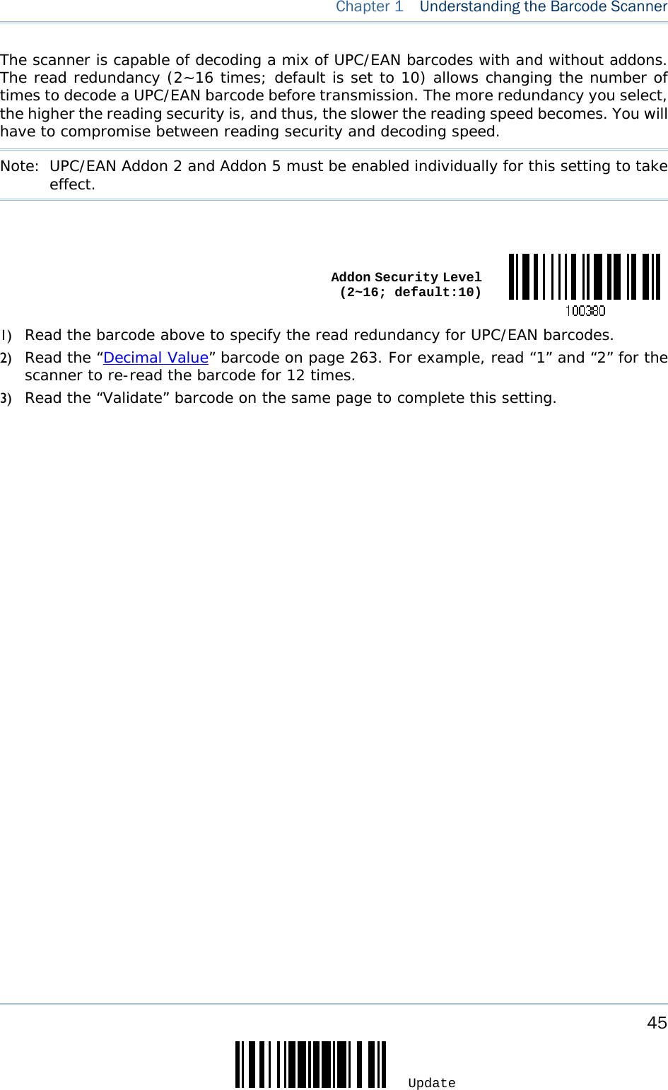
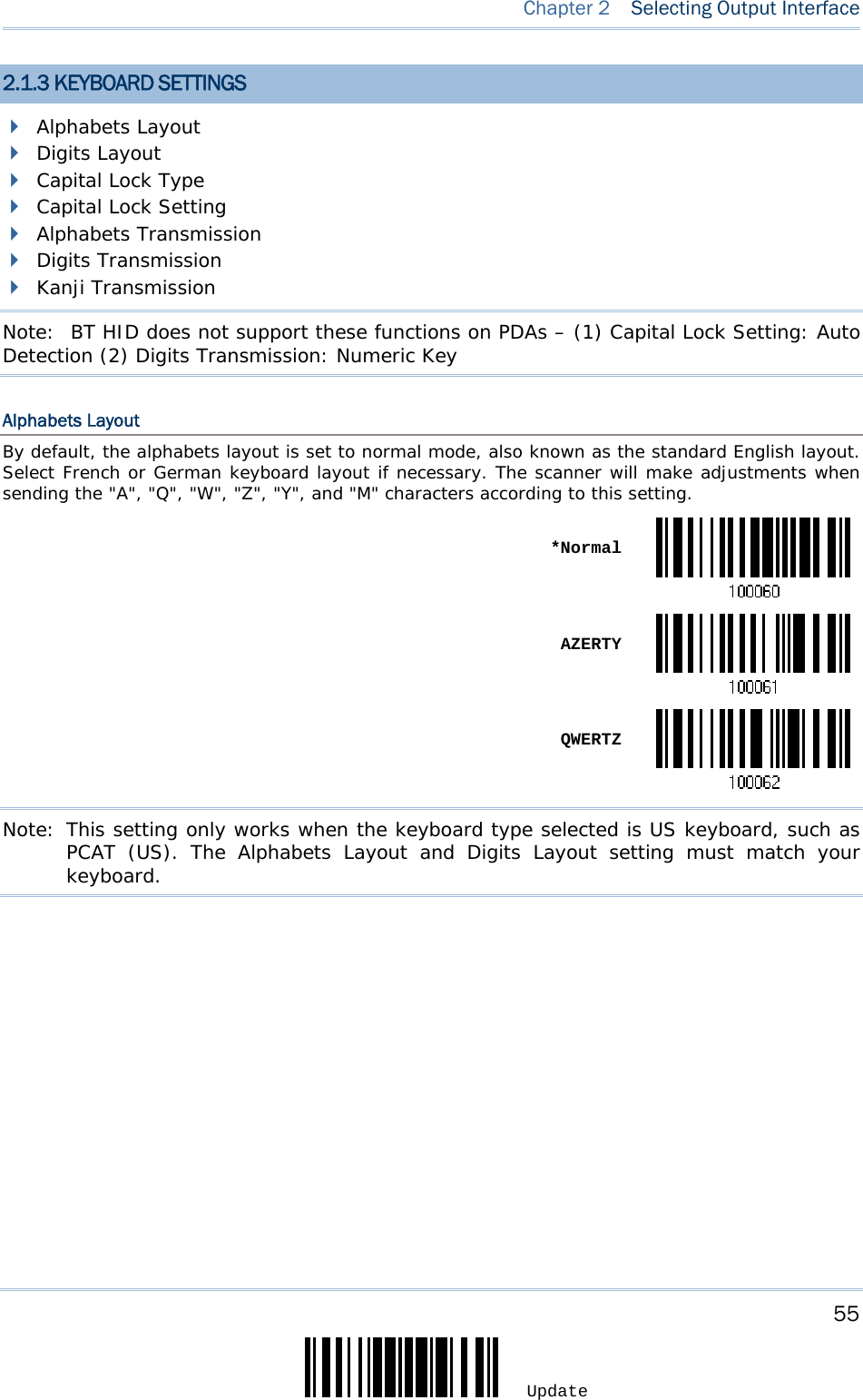

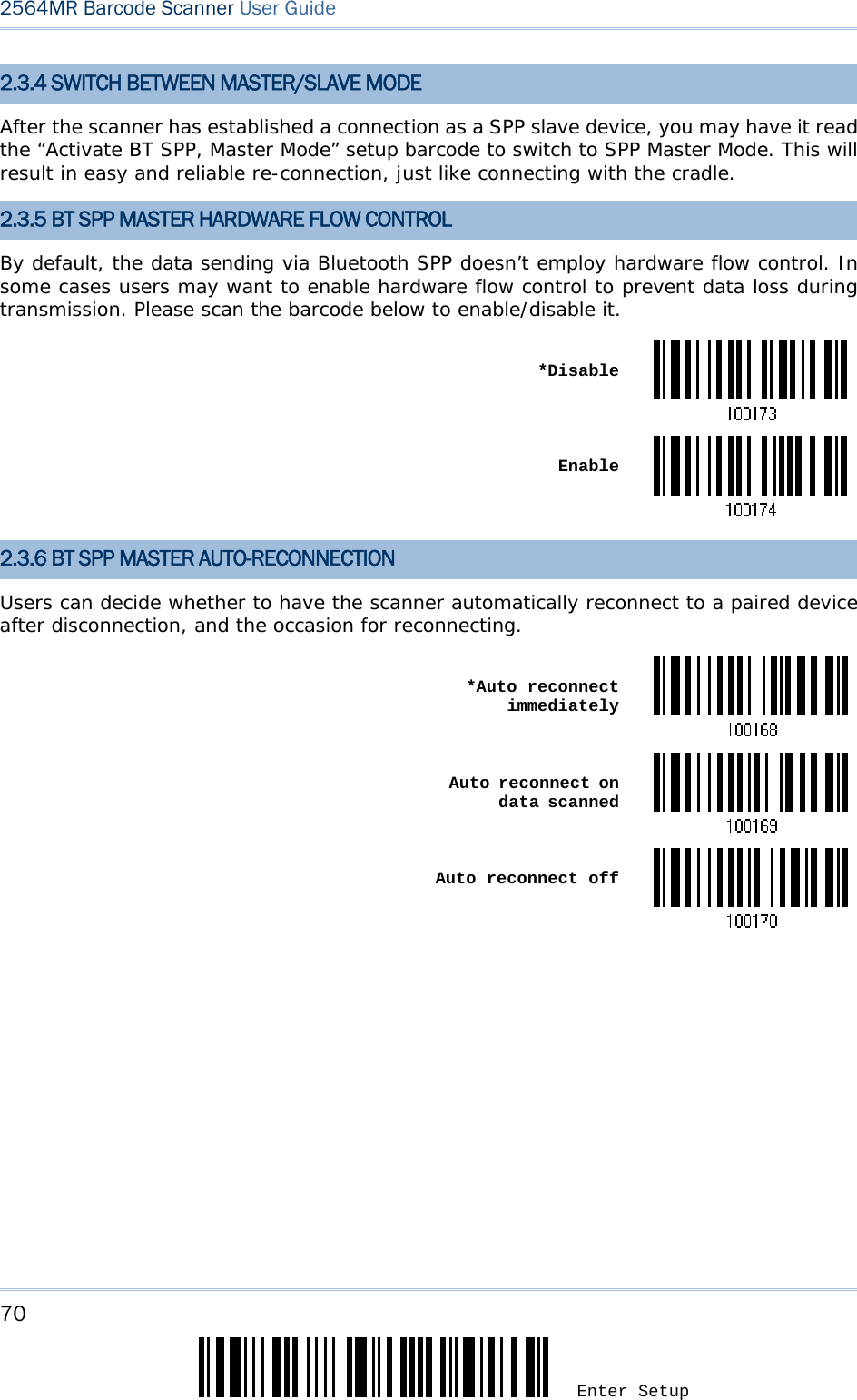
![57 Update Chapter 2 Selecting Output Interface Select a proper layout that matches the alphabets layout. The scanner will make adjustments according to this setting. Options Description Normal Depends on the [Shift] key or [Shift Lock] setting Lower Row For QWERTY or QWERTZ keyboard Upper Row For AZERTY keyboard *Normal Upper Row Lower RowNote: This setting is to be used with the Character Substitution setting when support to certain keyboard types (languages) is unavailable but required. Capital Lock Type & Setting In order to send the alphabets with correct case, the scanner needs to know the status of Caps Lock on the keyboard. Incorrect settings may result in reversed case of the alphabets being transmitted. Cap Lock Type Description Normal Normal type Capital Lock When enabled, the keys of alphabetic characters will be interpreted as capital letters. However, this does not affect the number or punctuation keys. Shift Lock When enabled, the keys of alphabetic characters will be interpreted as capital letters. In addition, this affects the number or punctuation keys. *Normal Shift Lock Capital Lock](https://usermanual.wiki/CipherLab/2564/User-Guide-3359037-Page-68.png)
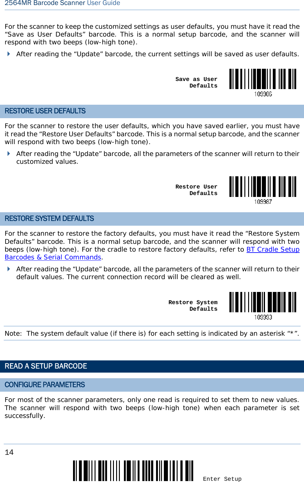
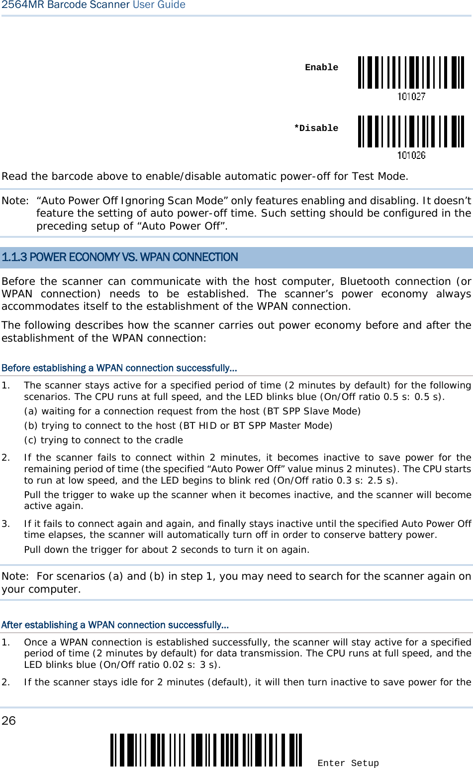
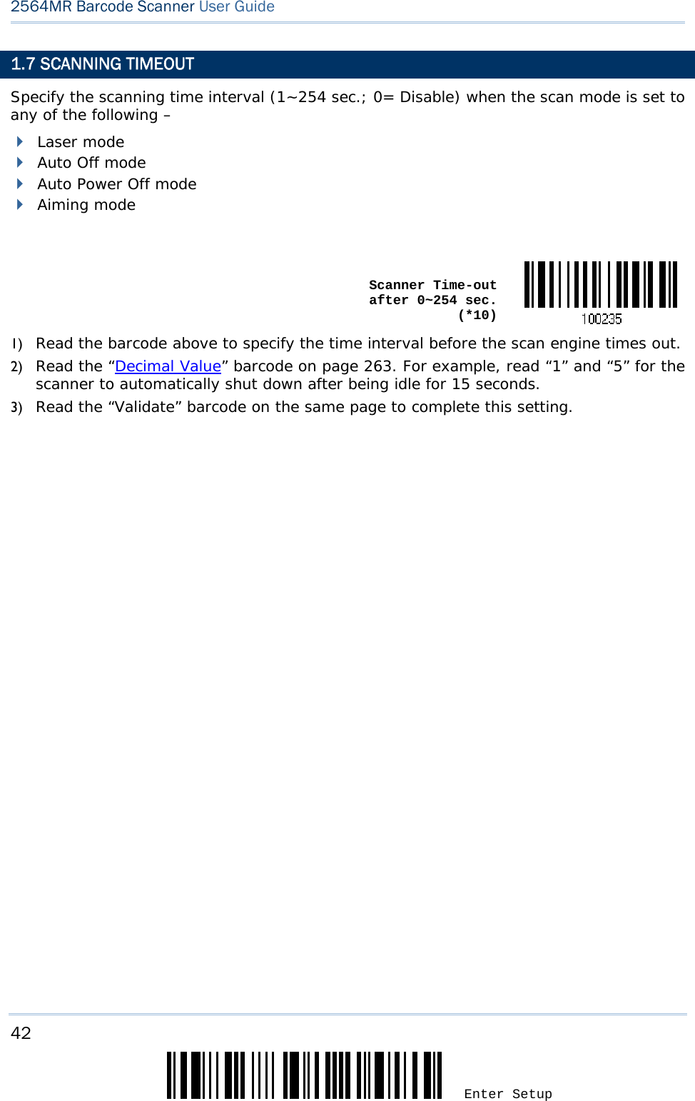
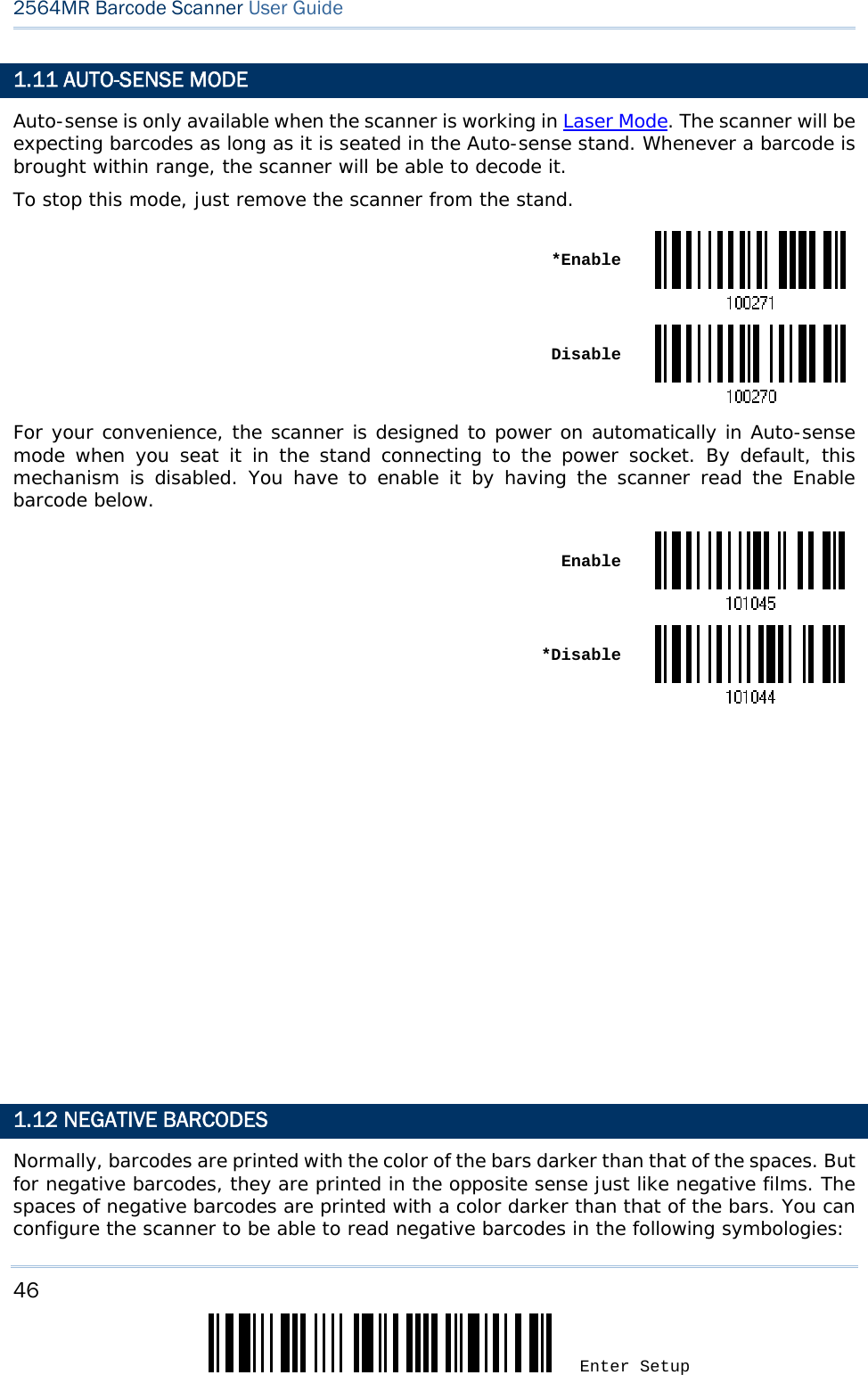
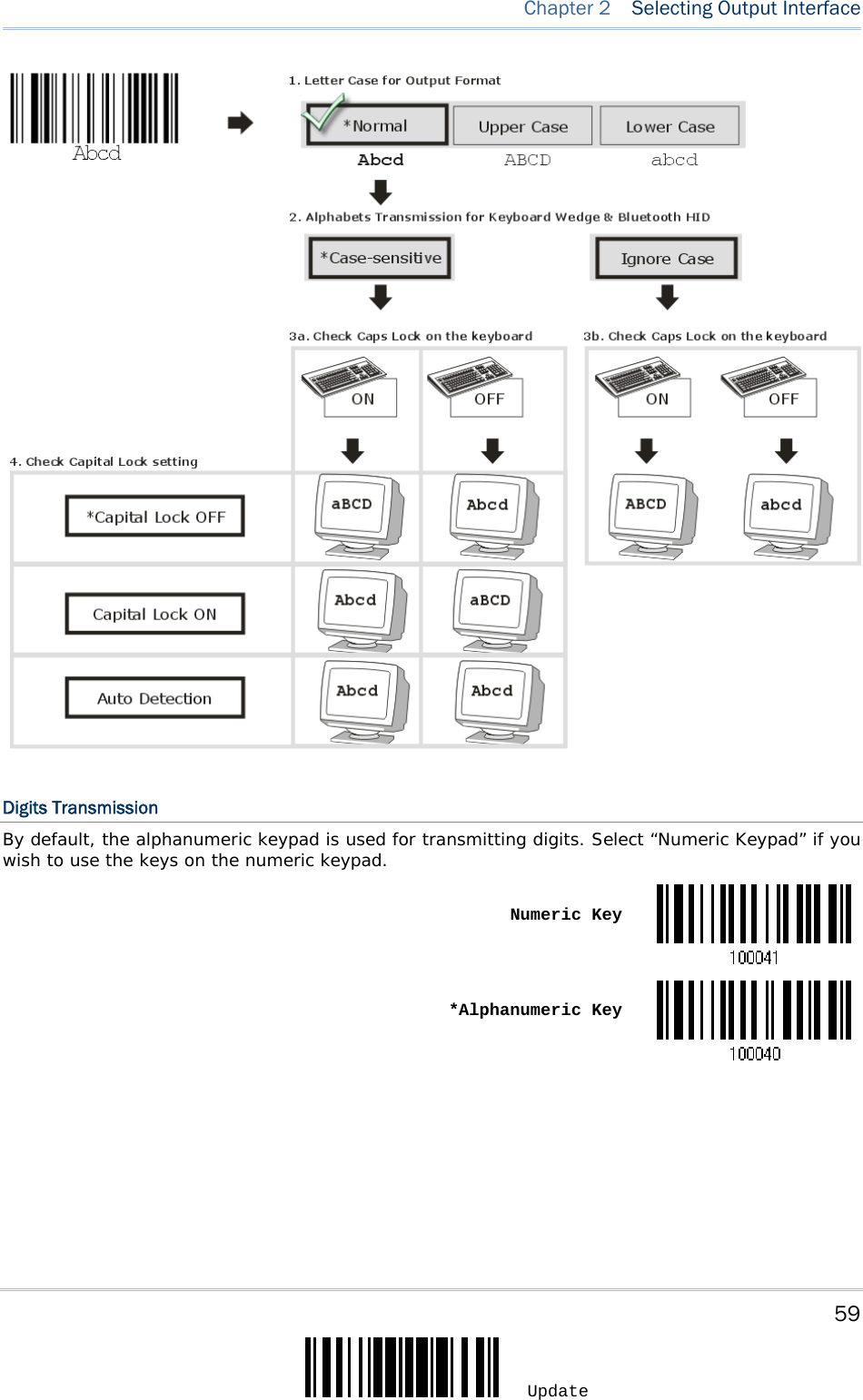
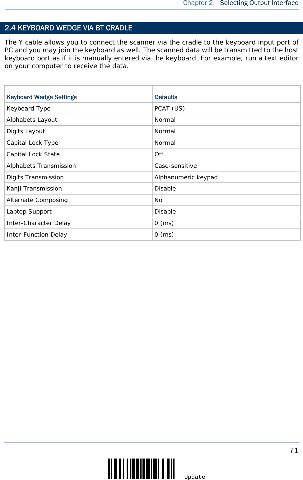
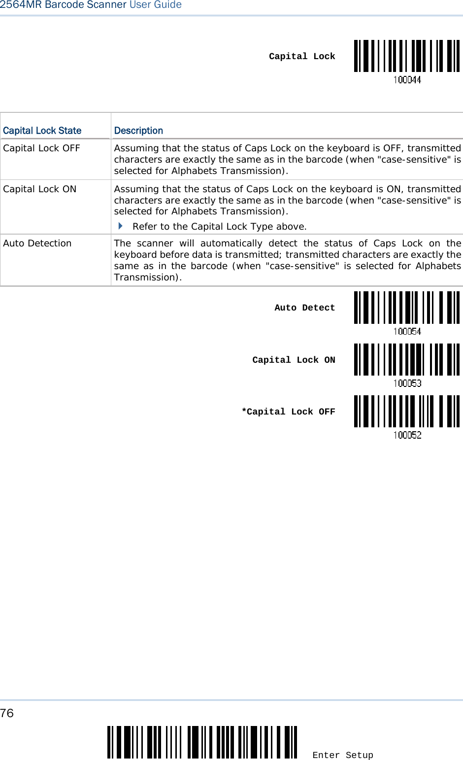
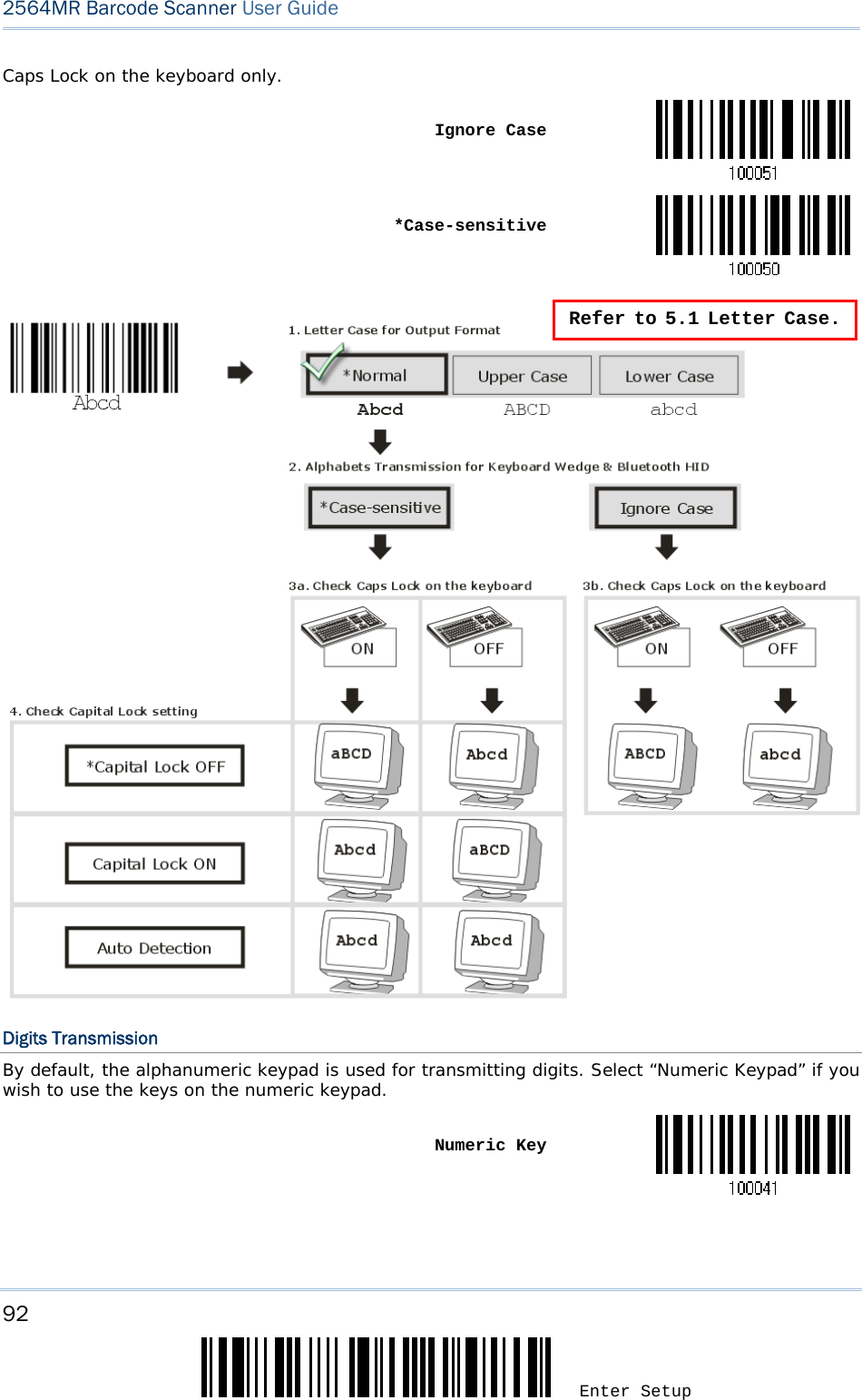
![58 Enter Setup 2564MR Barcode Scanner User Guide Capital Lock State Description Capital Lock OFF Assuming that the status of Caps Lock on the keyboard is OFF, transmitted characters are exactly the same as in the barcode (when "case-sensitive" is selected for Alphabets Transmission). Capital Lock ON Assuming that the status of Caps Lock on the keyboard is ON, transmitted characters are exactly the same as in the barcode (when "case-sensitive" is selected for Alphabets Transmission). Refer to the Capital Lock Type above. Auto Detection The scanner will automatically detect the status of Caps Lock on the keyboard before data is transmitted; transmitted characters are exactly the same as in the barcode (when "case-sensitive" is selected for Alphabets Transmission). This setting is not supported on PDAs. Auto Detect Capital Lock ON *Capital Lock OFF Alphabets Transmission By default, the alphabets transmission is case-sensitive, meaning that the alphabets will be transmitted according to their original case, the status of Caps Lock on the keyboard, as well as the Capital Lock setting. Select [Ignore Case] to have alphabets transmitted according to the status of Caps Lock on the keyboard only. Ignore Case *Case-sensitive Refer to 5.1 Letter Case.](https://usermanual.wiki/CipherLab/2564/User-Guide-3359037-Page-69.png)

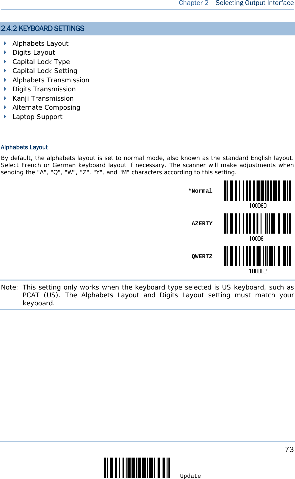
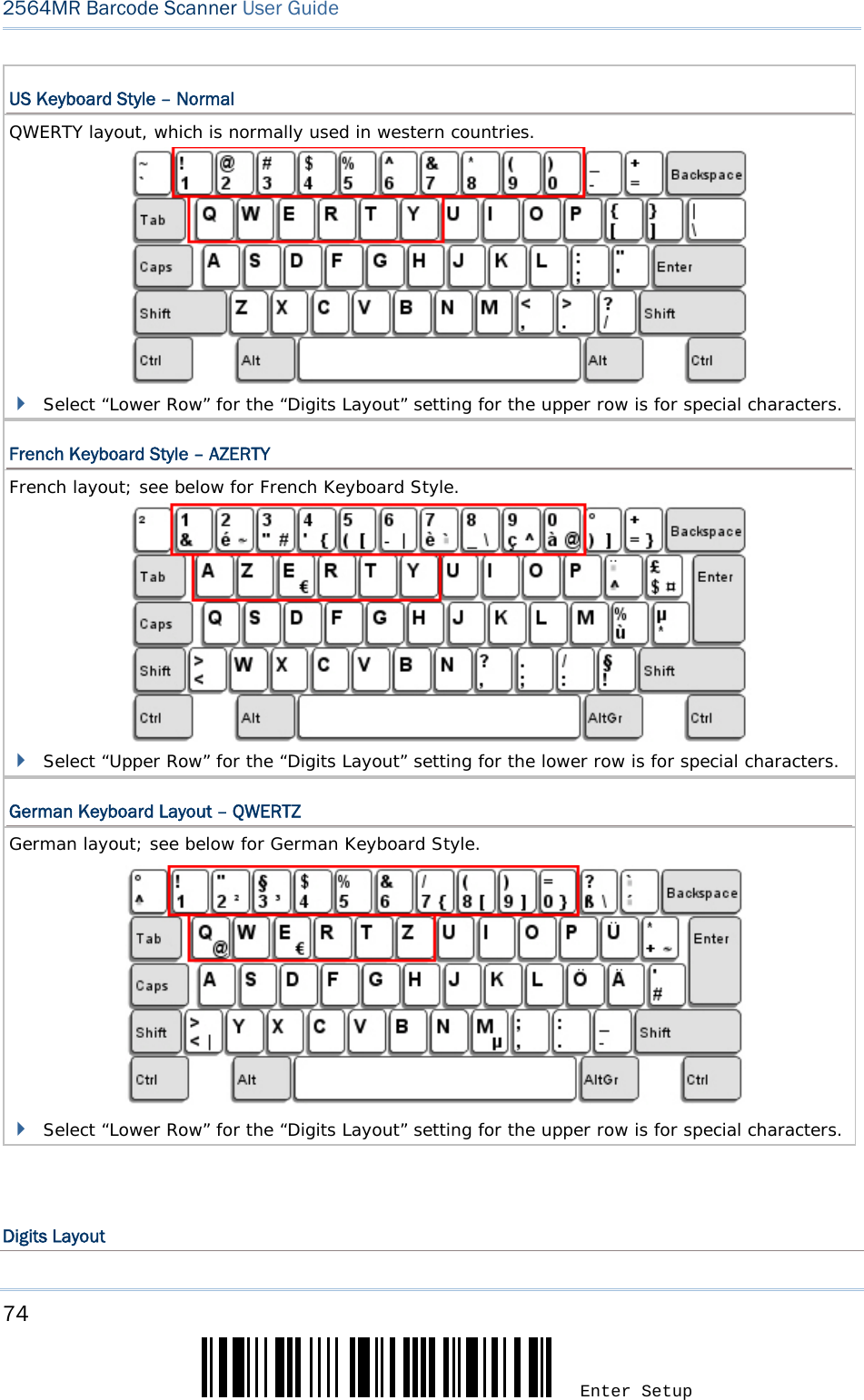
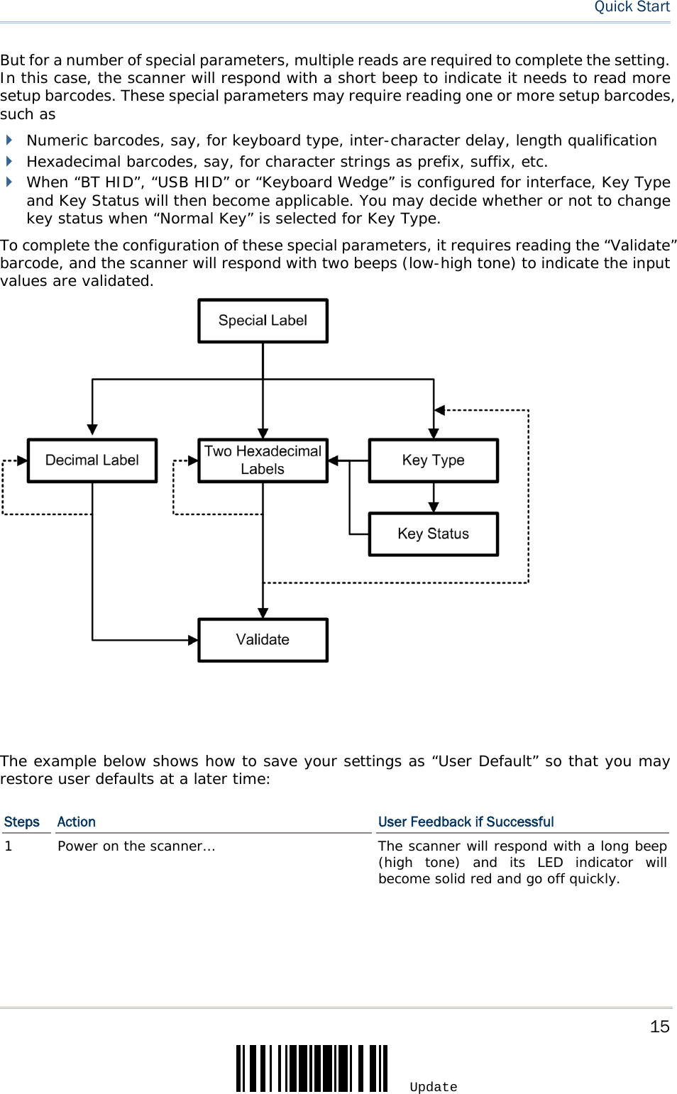
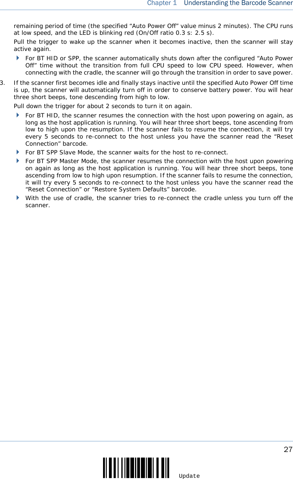
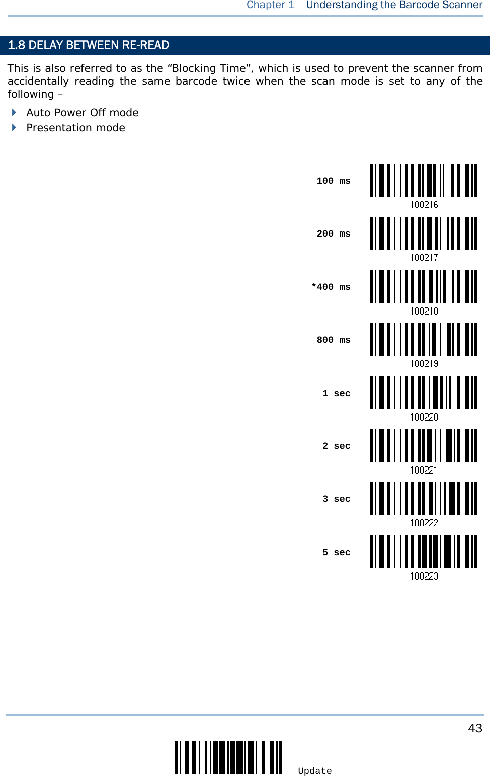
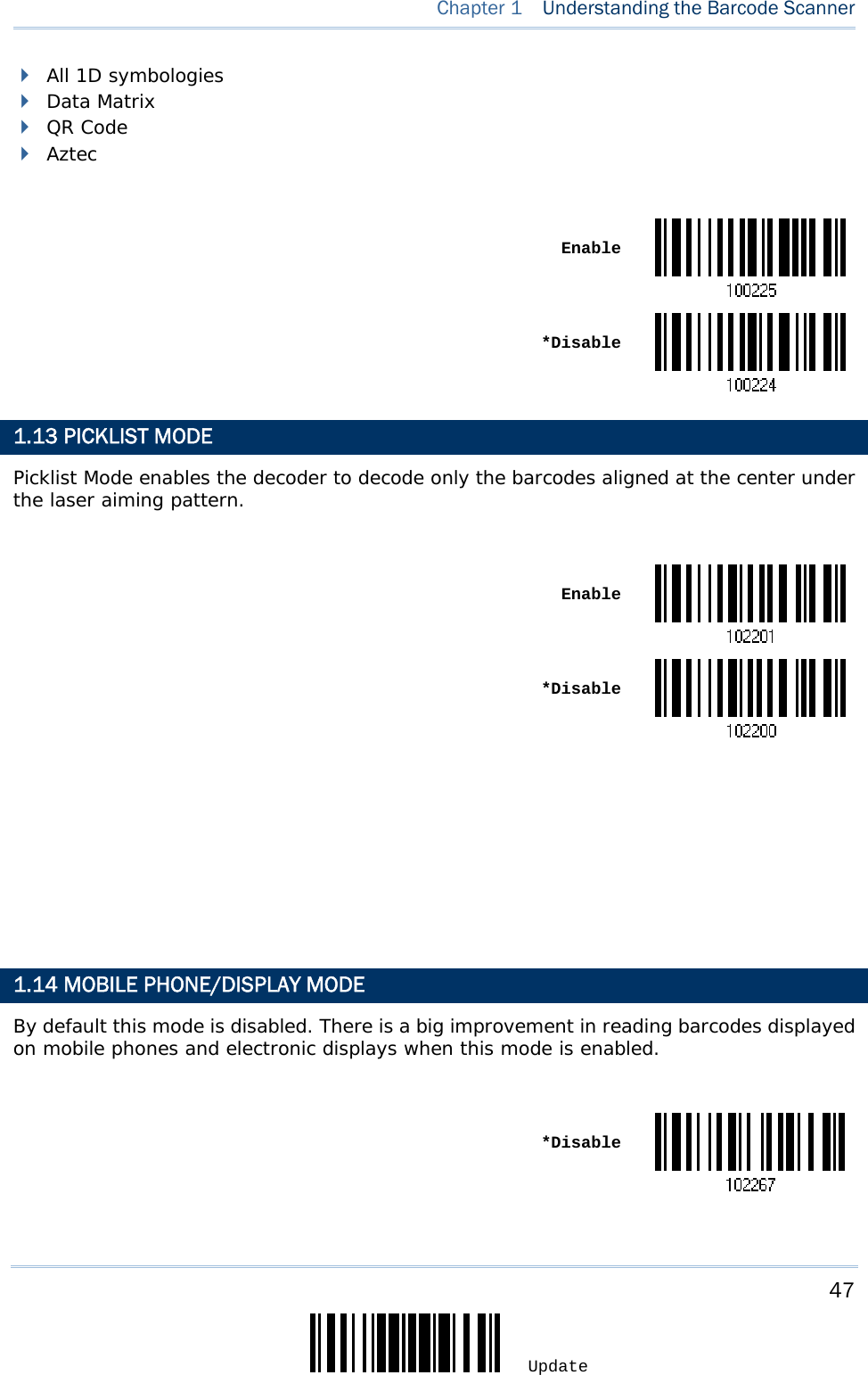
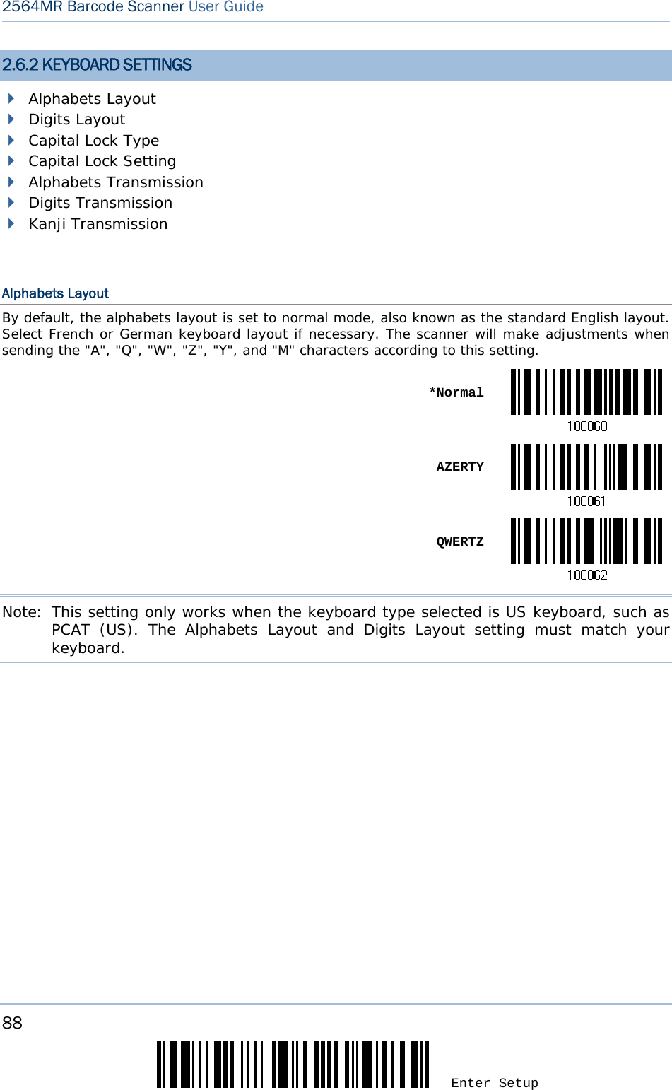
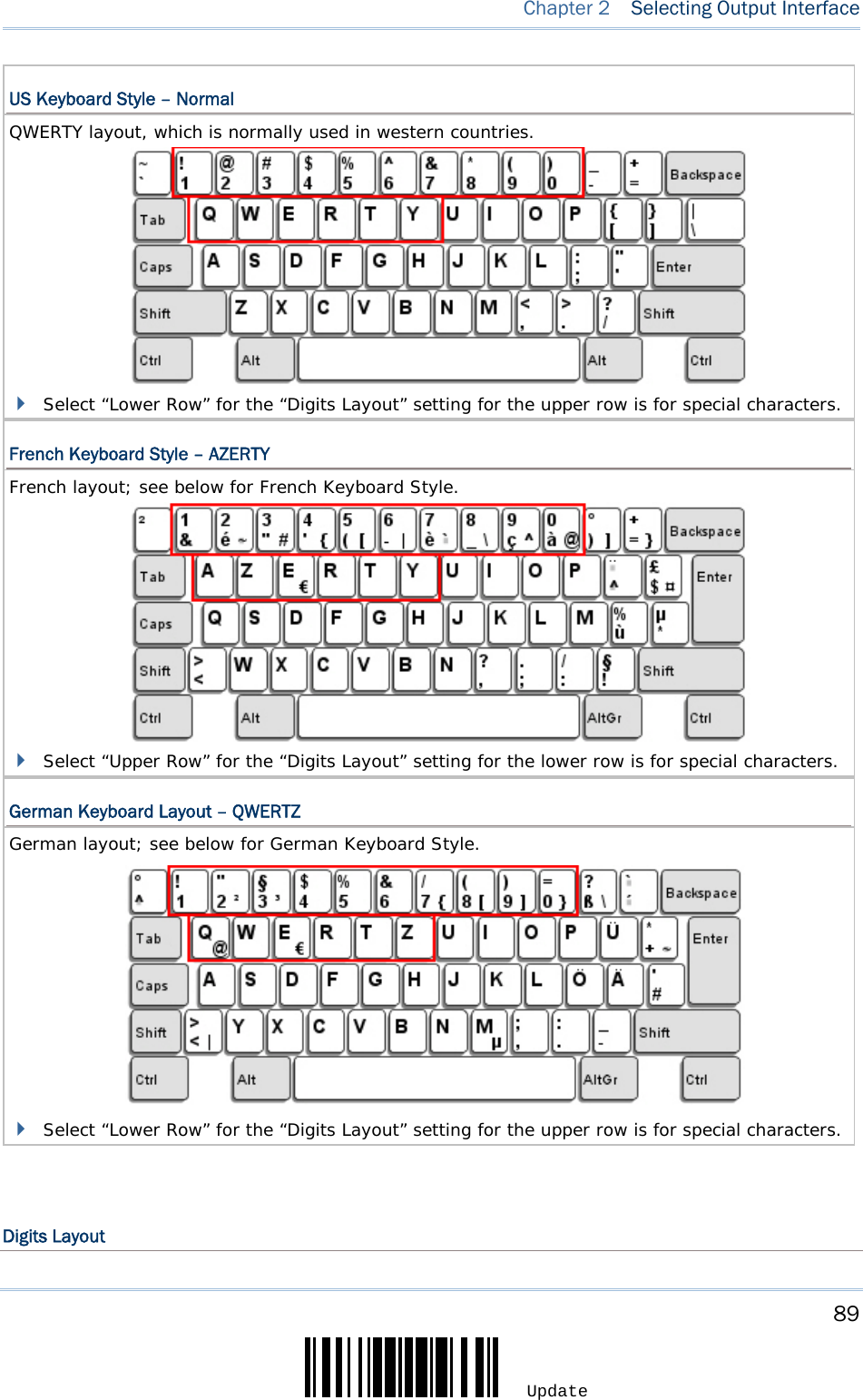
![75 Update Chapter 2 Selecting Output Interface Select a proper layout that matches the alphabets layout. The scanner will make adjustments according to this setting. Options Description Normal Depends on the [Shift] key or [Shift Lock] setting Lower Row For QWERTY or QWERTZ keyboard Upper Row For AZERTY keyboard *Normal Upper Row Lower RowNote: This setting is meant to be used with the Alphabets Layout; and perhaps with the Character Substitution setting when support to certain keyboard types (languages) is unavailable but required. Capital Lock Type & Setting In order to send the alphabets with correct case, the scanner needs to know the status of Caps Lock on the keyboard. Incorrect settings may result in reversed case of the alphabets being transmitted. Cap Lock Type Description Normal Normal type Capital Lock When enabled, the keys of alphabetic characters will be interpreted as capital letters. However, this does not affect the number or punctuation keys. Shift Lock When enabled, the keys of alphabetic characters will be interpreted as capital letters. In addition, this affects the number or punctuation keys. *Normal Shift Lock](https://usermanual.wiki/CipherLab/2564/User-Guide-3359037-Page-86.png)
![77 Update Chapter 2 Selecting Output Interface Alphabets Transmission By default, the alphabets transmission is case-sensitive, meaning that the alphabets will be transmitted according to their original case, the status of Caps Lock on the keyboard, as well as the Capital Lock setting. Select [Ignore Case] to have alphabets transmitted according to the status of Caps Lock on the keyboard only. Ignore Case *Case-sensitive Refer to 5.1 Letter Case.](https://usermanual.wiki/CipherLab/2564/User-Guide-3359037-Page-88.png)
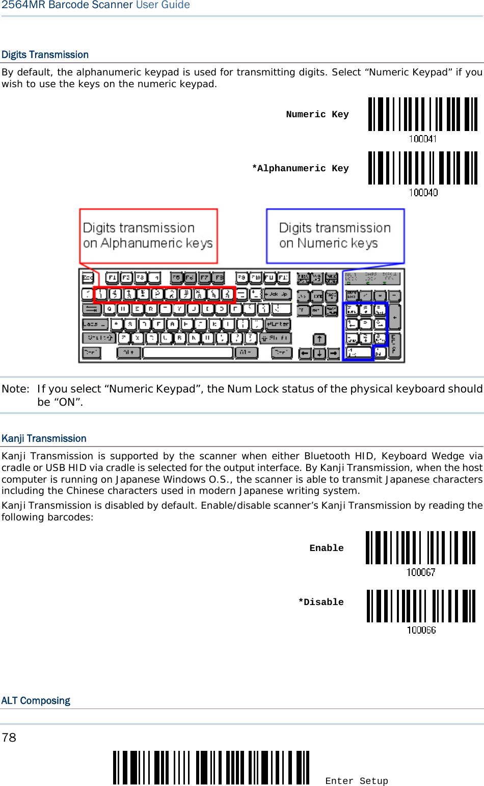
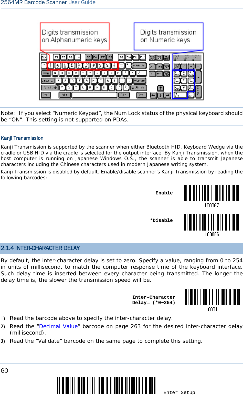
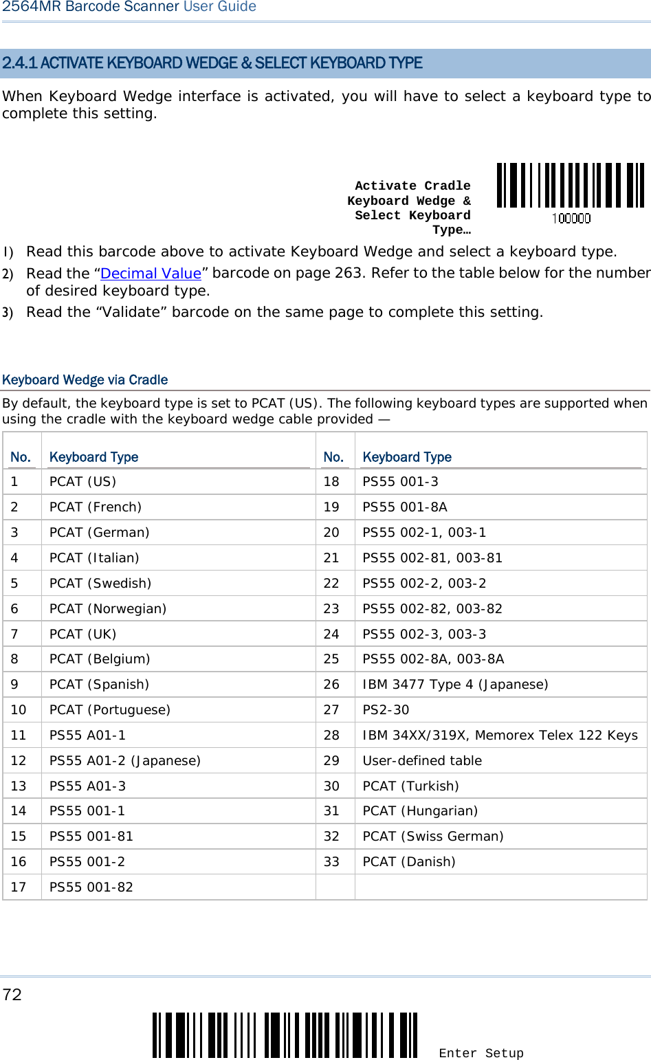
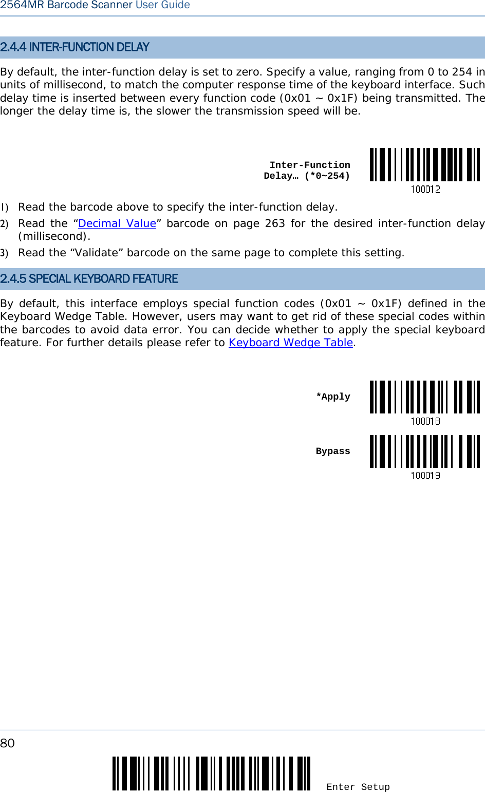
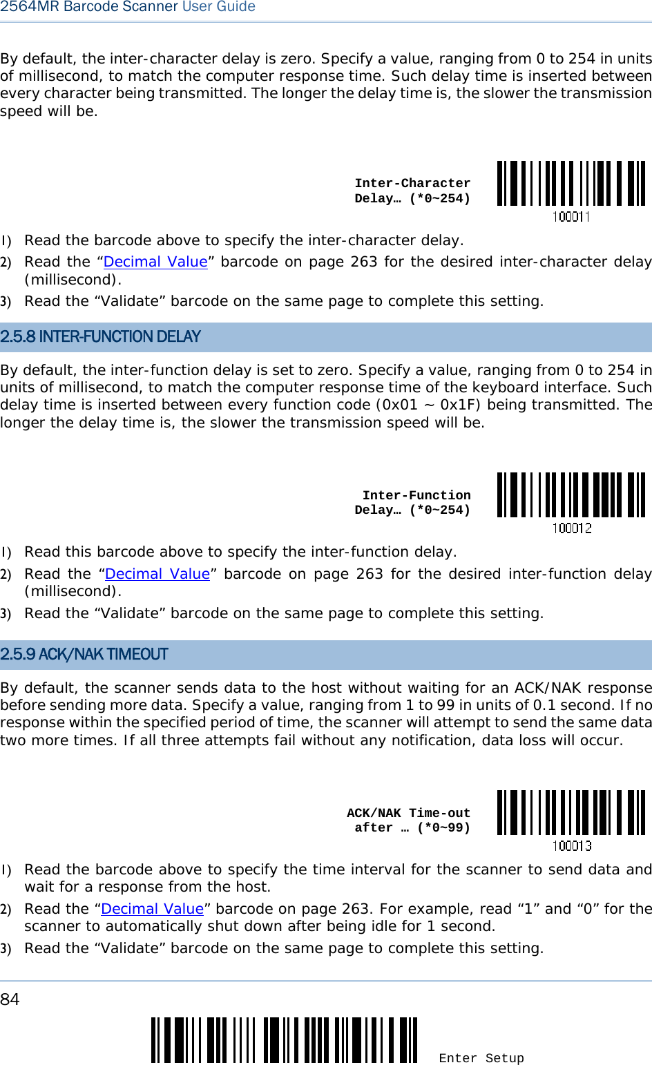
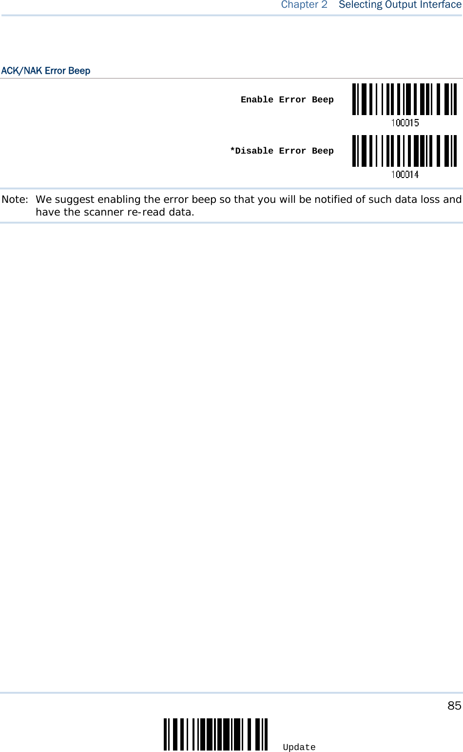
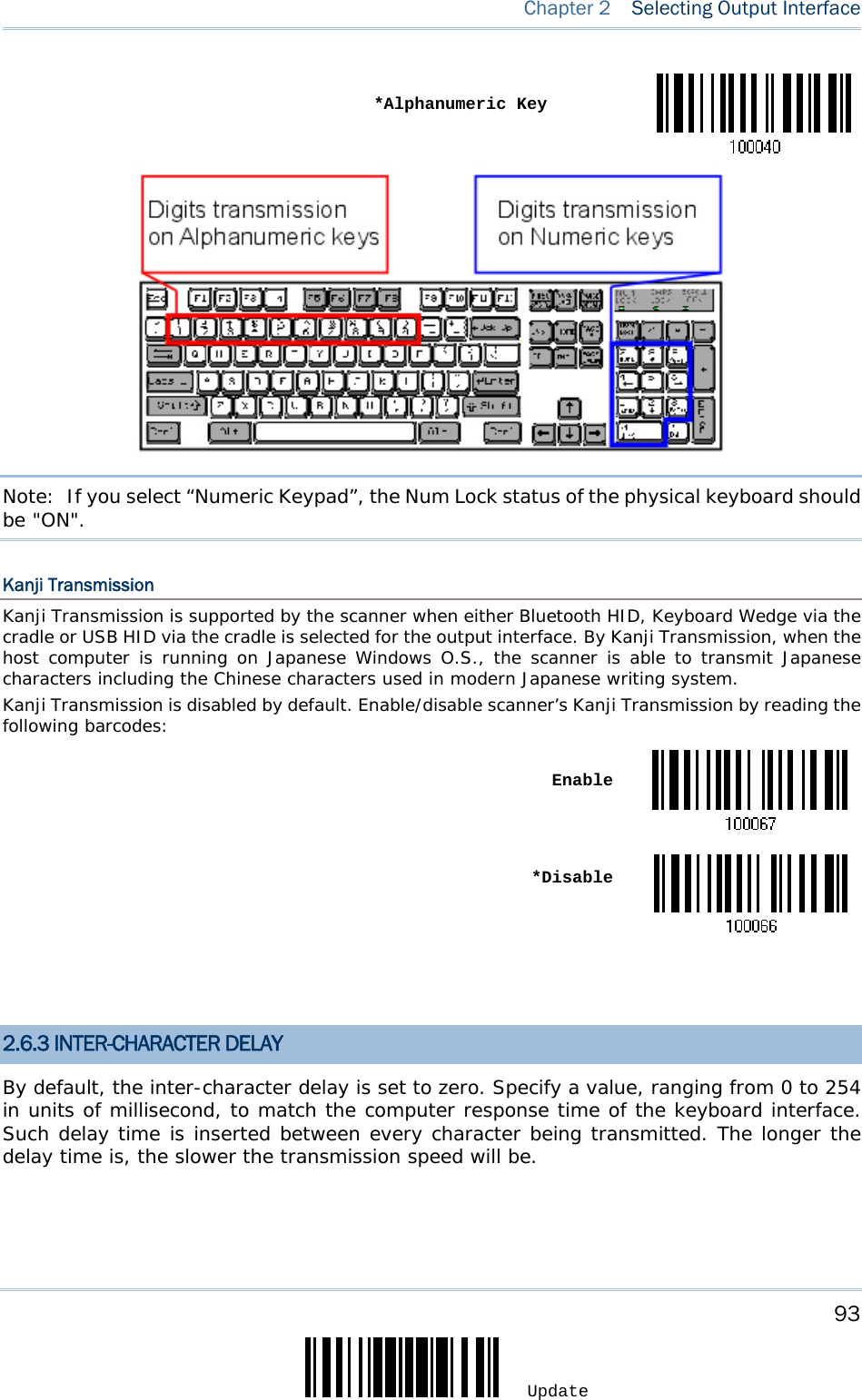
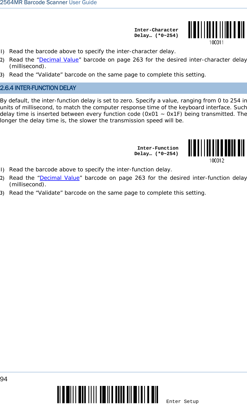
![79 Update Chapter 2 Selecting Output Interface By default, Alternate key composing is disabled. Select [Yes] to allow emulating Alternate key code of a specific keyboard character. For example, [Alt] + [065] will be sent to host for the character “A” regardless the keyboard type you are using. Yes *NoLaptop Support By default, laptop support is disabled. It is suggested to enable this feature if you connect the wedge cable to a laptop without an external keyboard being inter-connected. Enable *Disable2.4.3 INTER-CHARACTER DELAY By default, the inter-character delay is set to zero. Specify a value, ranging from 0 to 254 in units of millisecond, to match the computer response time of the keyboard interface. Such delay time is inserted between every character being transmitted. The longer the delay time is, the slower the transmission speed will be. Inter-Character Delay… (*0~254)1) Read the barcode above to specify the inter-character delay. 2) Read the “Decimal Value” barcode on page 263 for the desired inter-character delay (millisecond). 3) Read the “Validate” barcode on the same page to complete this setting.](https://usermanual.wiki/CipherLab/2564/User-Guide-3359037-Page-90.png)
![90 Enter Setup 2564MR Barcode Scanner User Guide Select a proper layout that matches the alphabets layout. The scanner will make adjustments according to this setting. Options Description Normal Depends on the [Shift] key or [Shift Lock] setting Lower Row For QWERTY or QWERTZ keyboard Upper Row For AZERTY keyboard *Normal Upper Row Lower RowNote: This setting is to be used with the Character Substitution setting when support to certain keyboard types (languages) is unavailable but required. Capital Lock Type & Setting In order to send the alphabets with correct case, the scanner needs to know the status of Caps Lock on the keyboard. Incorrect settings may result in reversed case of the alphabets being transmitted. Cap Lock Type Description Normal Normal type](https://usermanual.wiki/CipherLab/2564/User-Guide-3359037-Page-101.png)
![91 Update Chapter 2 Selecting Output Interface Capital Lock When enabled, the keys of alphabetic characters will be interpreted as capital letters. However, this does not affect the number or punctuation keys. Shift Lock When enabled, the keys of alphabetic characters will be interpreted as capital letters. In addition, this affects the number or punctuation keys. *Normal Shift Lock Capital LockCapital Lock State Description Capital Lock OFF Assuming that the status of Caps Lock on the keyboard is OFF, transmitted characters are exactly the same as in the barcode (when "case-sensitive" is selected for Alphabets Transmission). Capital Lock ON Assuming that the status of Caps Lock on the keyboard is ON, transmitted characters are exactly the same as in the barcode (when "case-sensitive" is selected for Alphabets Transmission). Refer to the Capital Lock Type above. Auto Detection The scanner will automatically detect the status of Caps Lock on the keyboard before data is transmitted; transmitted characters are exactly the same as in the barcode (when "case-sensitive" is selected for Alphabets Transmission). Auto Detect Capital Lock ON *Capital Lock OFF Alphabets Transmission By default, the alphabets transmission is case-sensitive, meaning that the alphabets will be transmitted according to their original case, the status of Caps Lock on the keyboard, as well as the Capital Lock setting. Select [Ignore Case] to have alphabets transmitted according to the status of](https://usermanual.wiki/CipherLab/2564/User-Guide-3359037-Page-102.png)
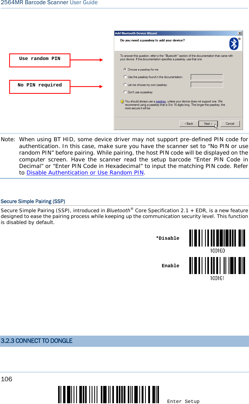
![107 Update Chapter 3 Setting up a WPAN Connection The procedure goes through associating devices for establishing a WPAN connection, which is pretty much the same except for the software you are using. If your computer is running Microsoft® Windows® XP Service Pack 3 (SP3) or Windows Vista® Service Pack 1 (SP1), you can use the software support that Windows® includes, or you can use the driver that the device manufacturer provides. Now, let’s try using the software support that Windows® XP Service Pack 2 includes. BT HID Procedure By default, BT HID is activated on the scanner, and the keyboard type is set to PCAT (US). When BT HID is re-activated, you will have to select a keyboard type to complete this setting. The procedure is the same as for BT SPP. Refer to steps 1~11 below. BT SPP Procedure 1. Turn on the Bluetooth® function on your computer, running Windows XP SP2. 2. Double-click the Bluetooth® icon from the lower right of the taskbar. Alternatively, you may go to Control Panel > Bluetooth Devices. 3. Click [Add] to search devices nearby. 4. Turn on the scanner with correct WPAN settings, such as select BT SPP or BT HID, broadcasting enabled, authentication enabled, and PIN code specified, etc. Select the check box of [My device is set up and ready to be found] on your computer.](https://usermanual.wiki/CipherLab/2564/User-Guide-3359037-Page-118.png)
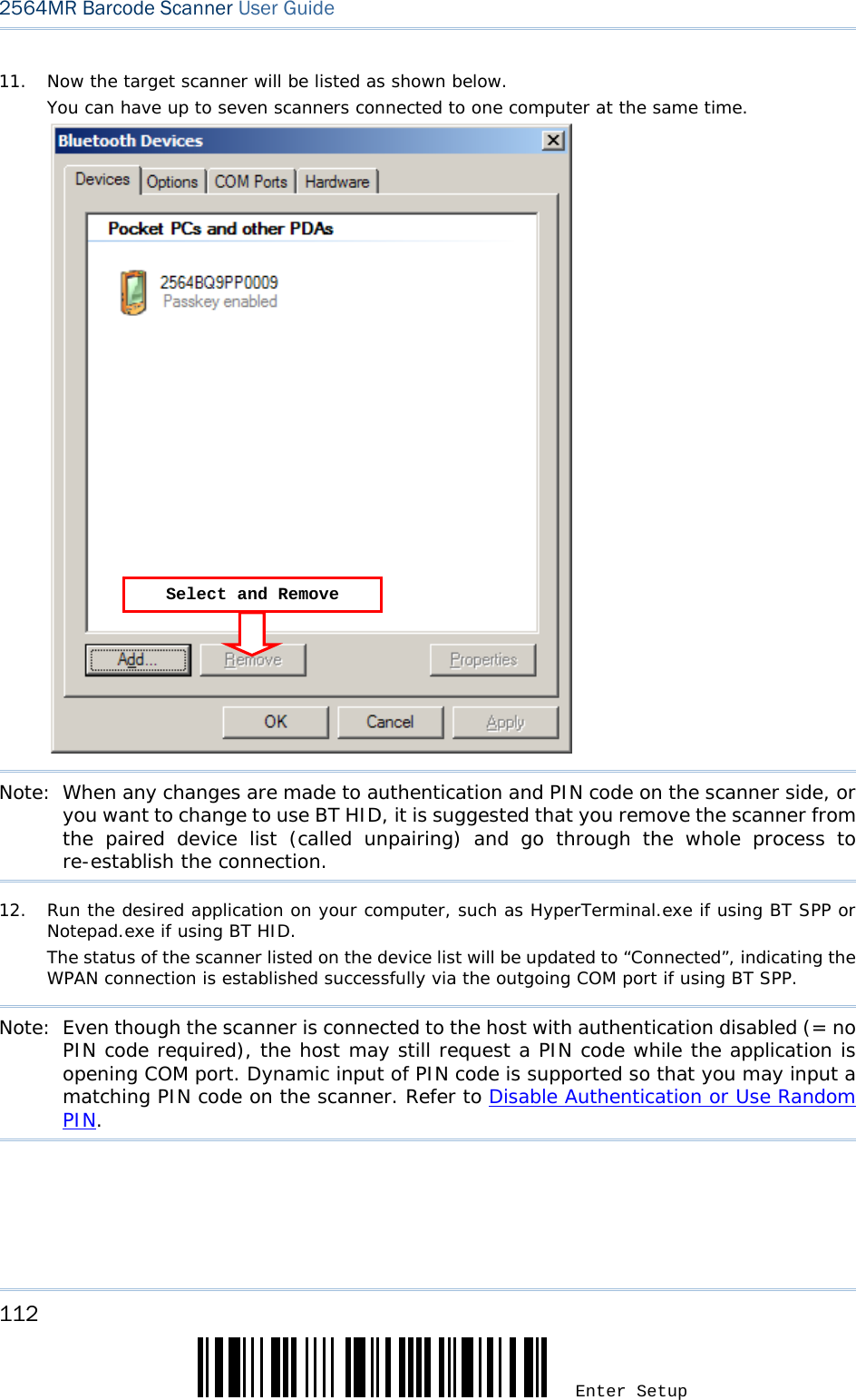
![108 Enter Setup 2564MR Barcode Scanner User Guide 5. Click [Next]. 6. Wait for a few seconds for the Wizard to search available devices nearby. The scanner will appear with its “serial number” as the device name. You may double-check the “Serial Number” label on the scanner to ensure connecting with the correct scanner. Select the target scanner. If the target scanner does not appear on the list, click [Search Again] to refresh the list. The scanner might enter Suspend Mode now, and you can press the trigger to have it active again (=discoverable). It will then stay active for a specified period of time (2 minutes by default) and wait for PC to establish a connection.](https://usermanual.wiki/CipherLab/2564/User-Guide-3359037-Page-119.png)
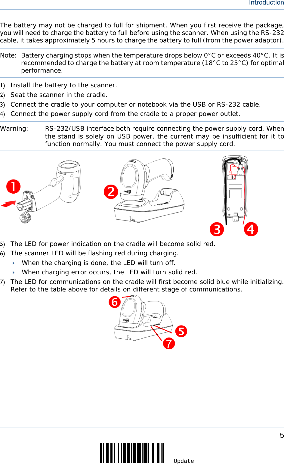
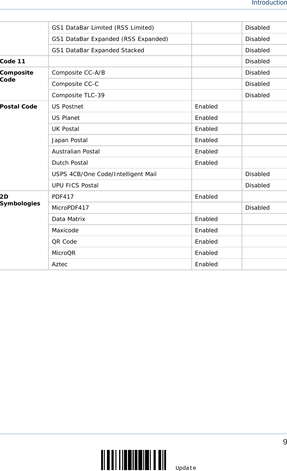
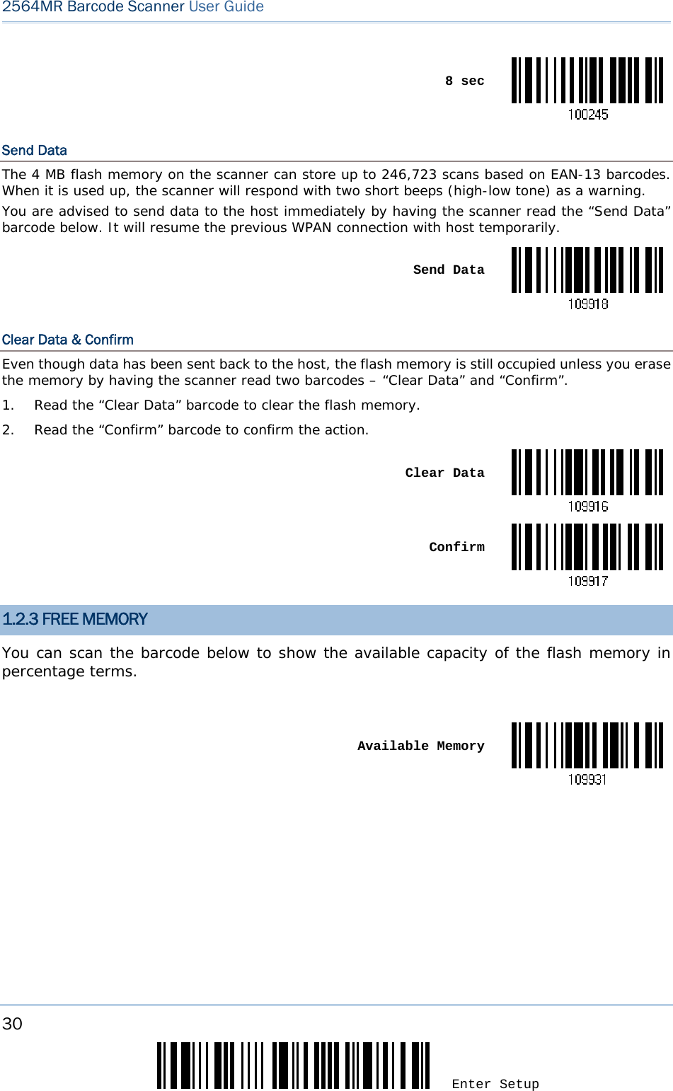
![109 Update Chapter 3 Setting up a WPAN Connection 7. Click [Next]. 8. Enter the passkey for authentication, which must be exactly the same as configured for the scanner.](https://usermanual.wiki/CipherLab/2564/User-Guide-3359037-Page-120.png)
![110 Enter Setup 2564MR Barcode Scanner User Guide 9. Click [Next]. Wait for a few seconds for Windows to exchange passkeys.](https://usermanual.wiki/CipherLab/2564/User-Guide-3359037-Page-121.png)
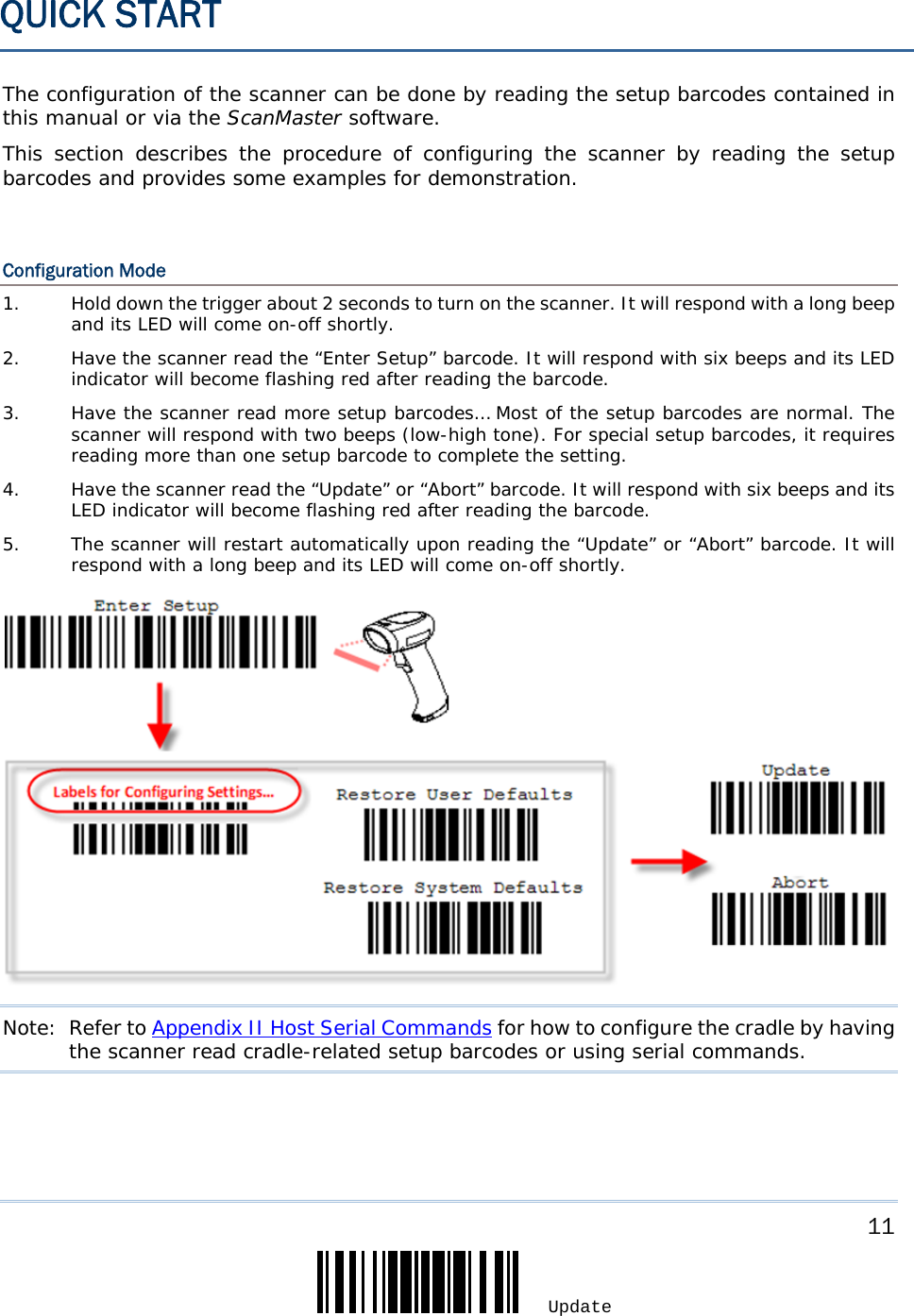
![111 Update Chapter 3 Setting up a WPAN Connection Note: When Bluetooth security is enabled without providing a pre-set PIN code, dynamic input of PIN code is supported. 10. Click [Finish]. 2564 as BT SPP Slave 2564 as BT SPP Master](https://usermanual.wiki/CipherLab/2564/User-Guide-3359037-Page-122.png)
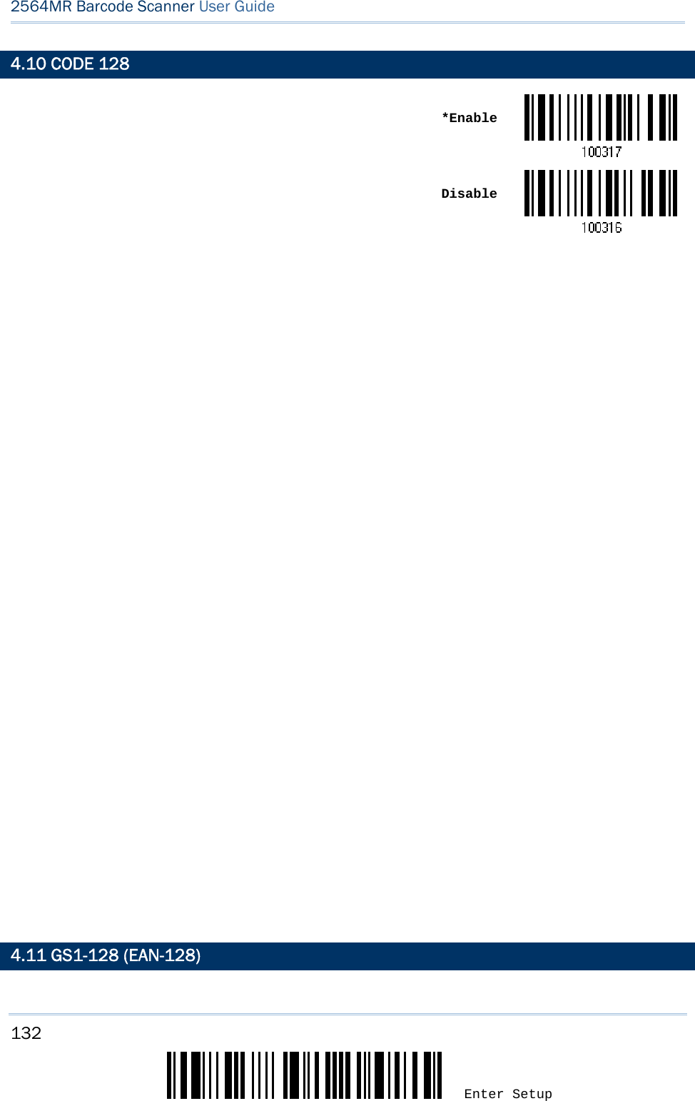
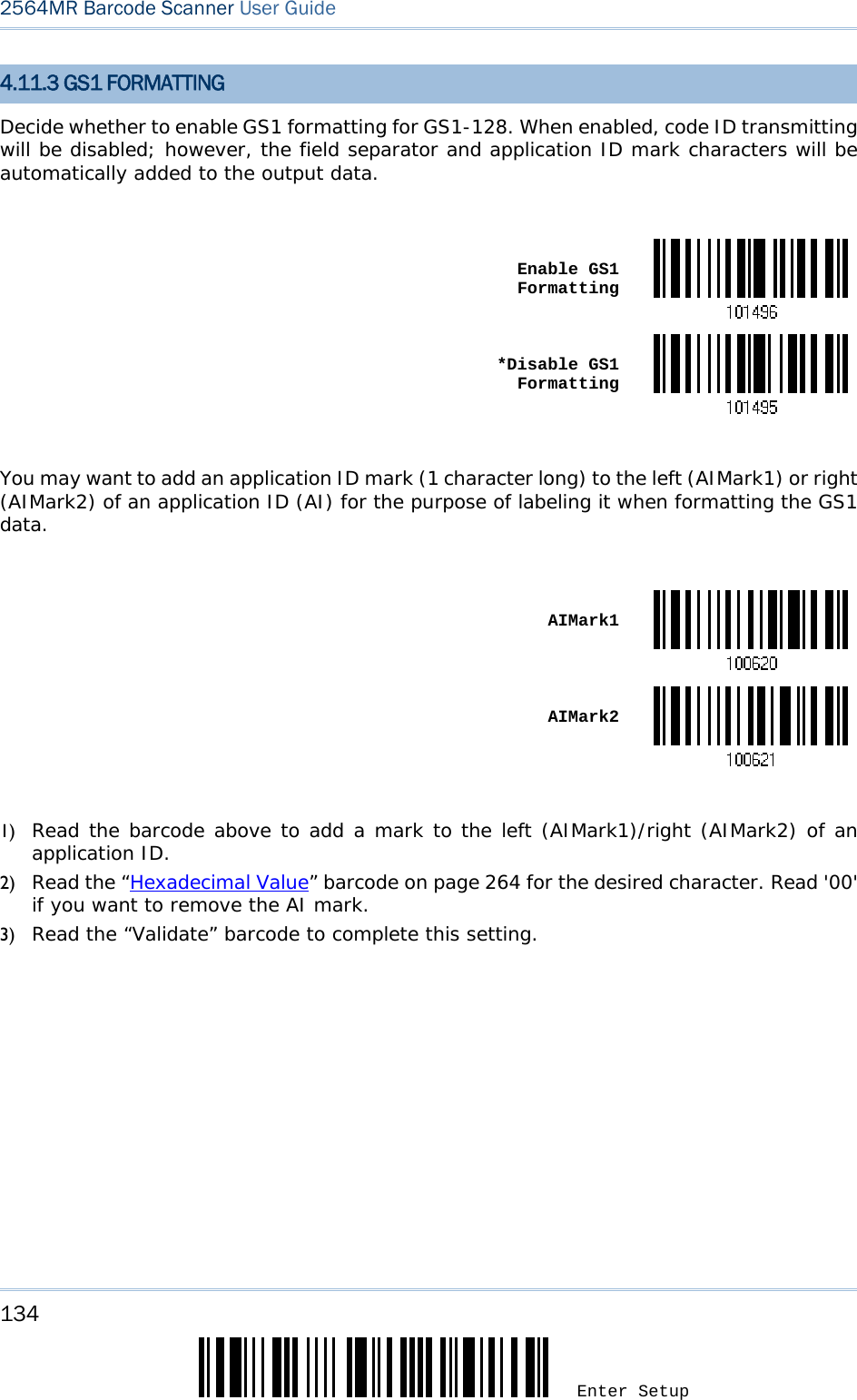
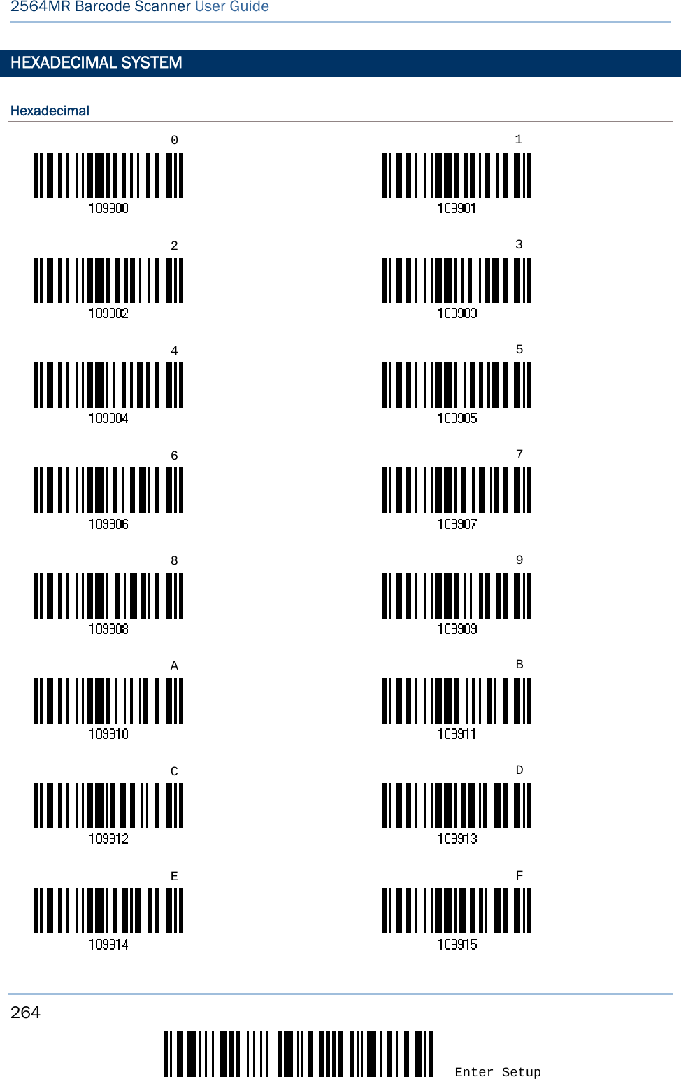
![133 Update Chapter 4 Changing Symbology Settings *Enable DisableNote: GS1-128 barcodes can be decoded only when this setting is enabled. 4.11.1 TRANSMIT CODE ID Decide whether to include the Code ID (“]C1”) in the data being transmitted. Transmit GS1-128 Code ID *Do Not Transmit4.11.2 FIELD SEPARATOR (GS CHARACTER) Decide whether to apply a field separator (to convert the FNC1 control character to human readable character). Enable Field Separator…1) Read the barcode above to enable field separator. 2) Read the “Hexadecimal Value” barcode on page 264 for the desired character string. 3) Read the “Validate” barcode to complete this setting. Note: GS1-128 barcodes start with the FNC1 control character to distinguish themselves from other uses of Code 128. FNC1 is also used to separate data fields in the GS1-128 barcodes.](https://usermanual.wiki/CipherLab/2564/User-Guide-3359037-Page-143.png)
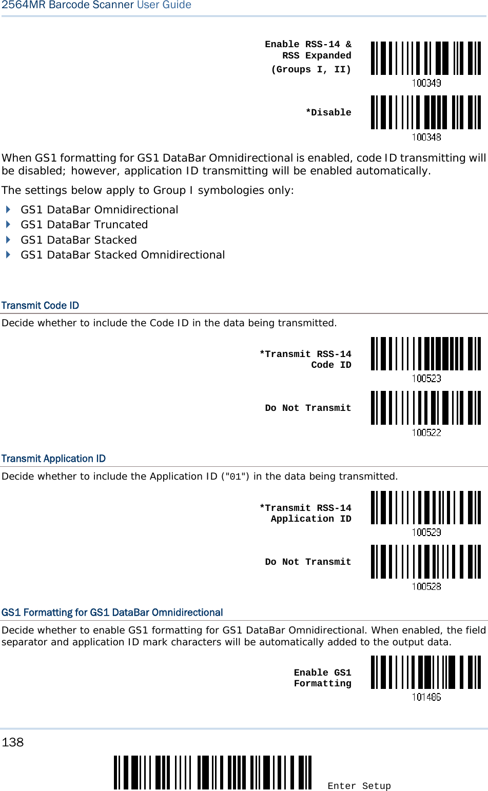
![137 Update Chapter 4 Changing Symbology Settings 4.13 GS1 DATABAR (RSS FAMILY) It is categorized into three groups: Group I — GS1 DataBar Omnidirectional (RSS-14) This group consists of the following: GS1 DataBar Omnidirectional GS1 DataBar Truncated GS1 DataBar Stacked GS1 DataBar Stacked Omnidirectional Group II — GS1 DataBar Expanded (RSS Expanded) This group consists of the following: GS1 DataBar Expanded GS1 DataBar Expanded Stacked Group III — GS1 DataBar Limited (RSS Limited) This group consists of the following: GS1 DataBar Limited 4.13.1 SELECT CODE ID Select a desired Code ID to use: “]e0“ (GS1 DataBar Code ID) “]C1” (GS1-128 Code ID) Use “]C1” *Use “]e0” 4.13.2 GS1 DATABAR OMNIDIRECTIONAL (RSS-14)](https://usermanual.wiki/CipherLab/2564/User-Guide-3359037-Page-147.png)
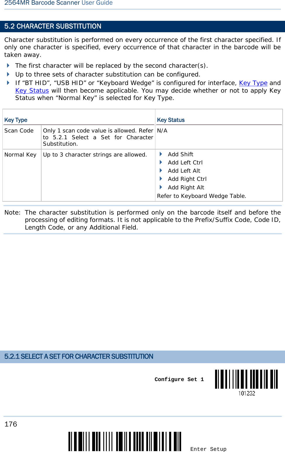
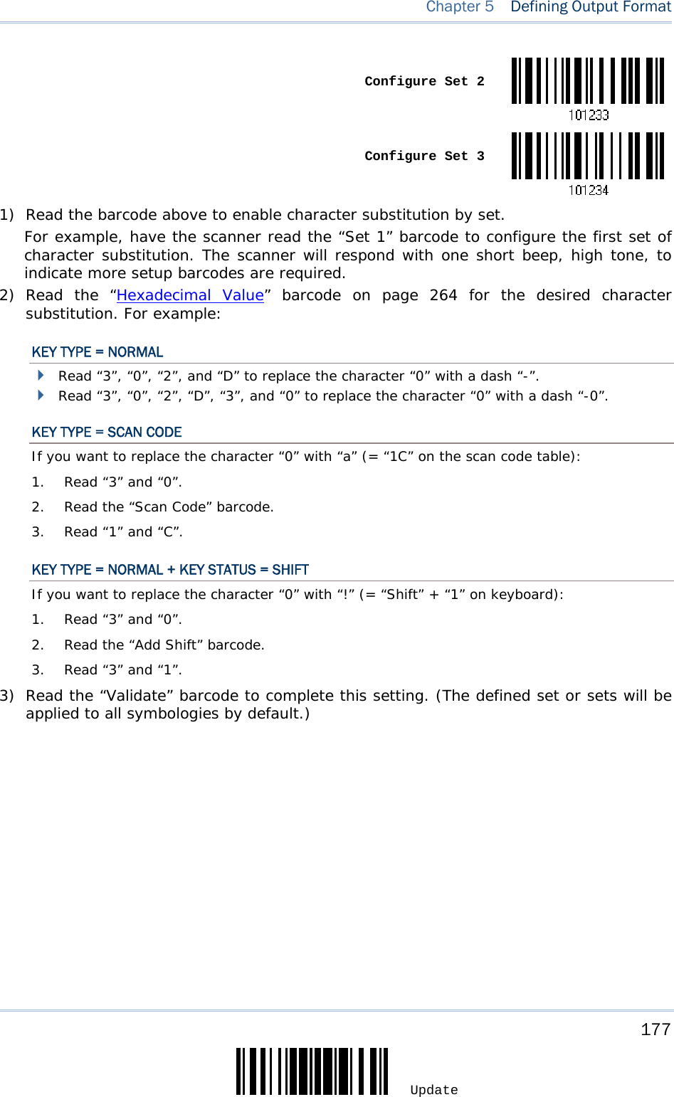
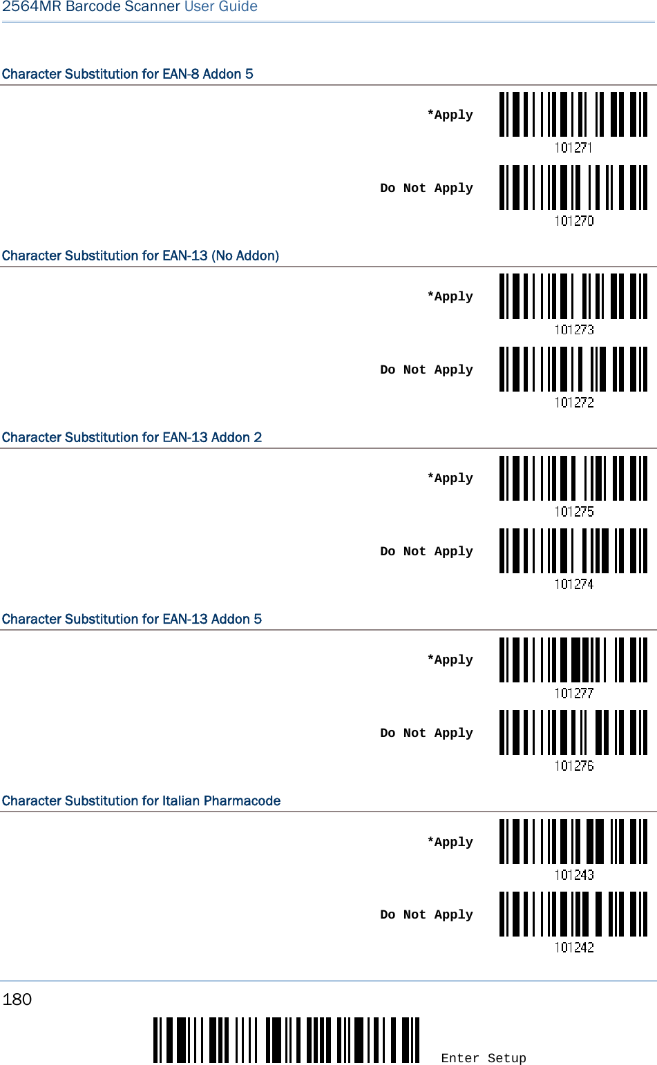
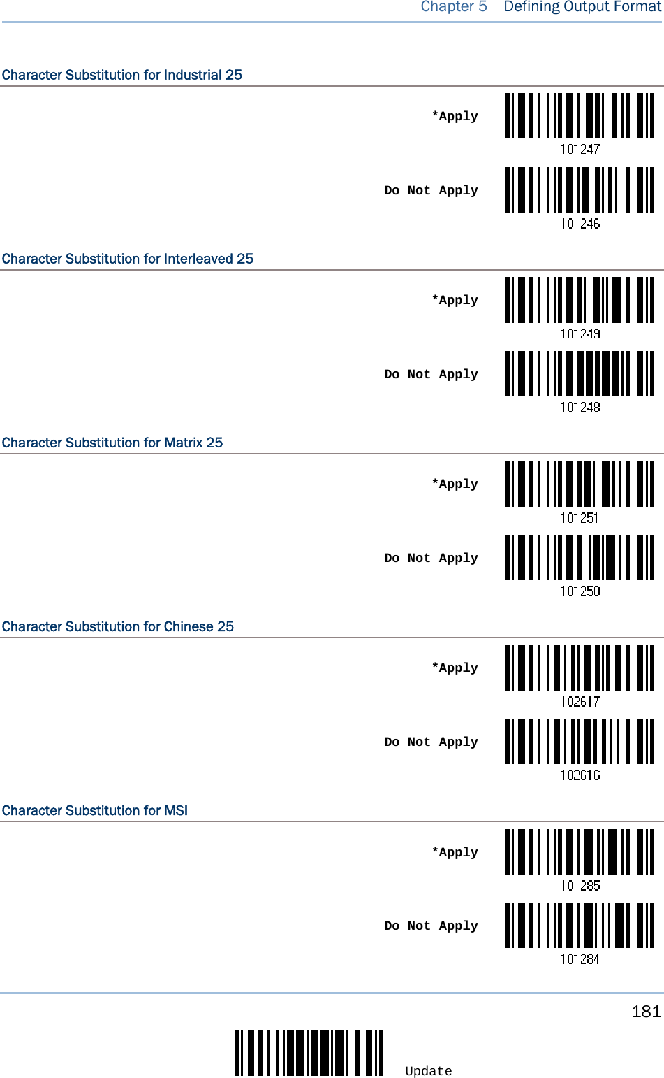
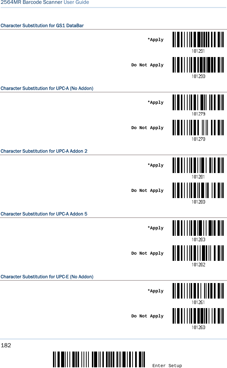
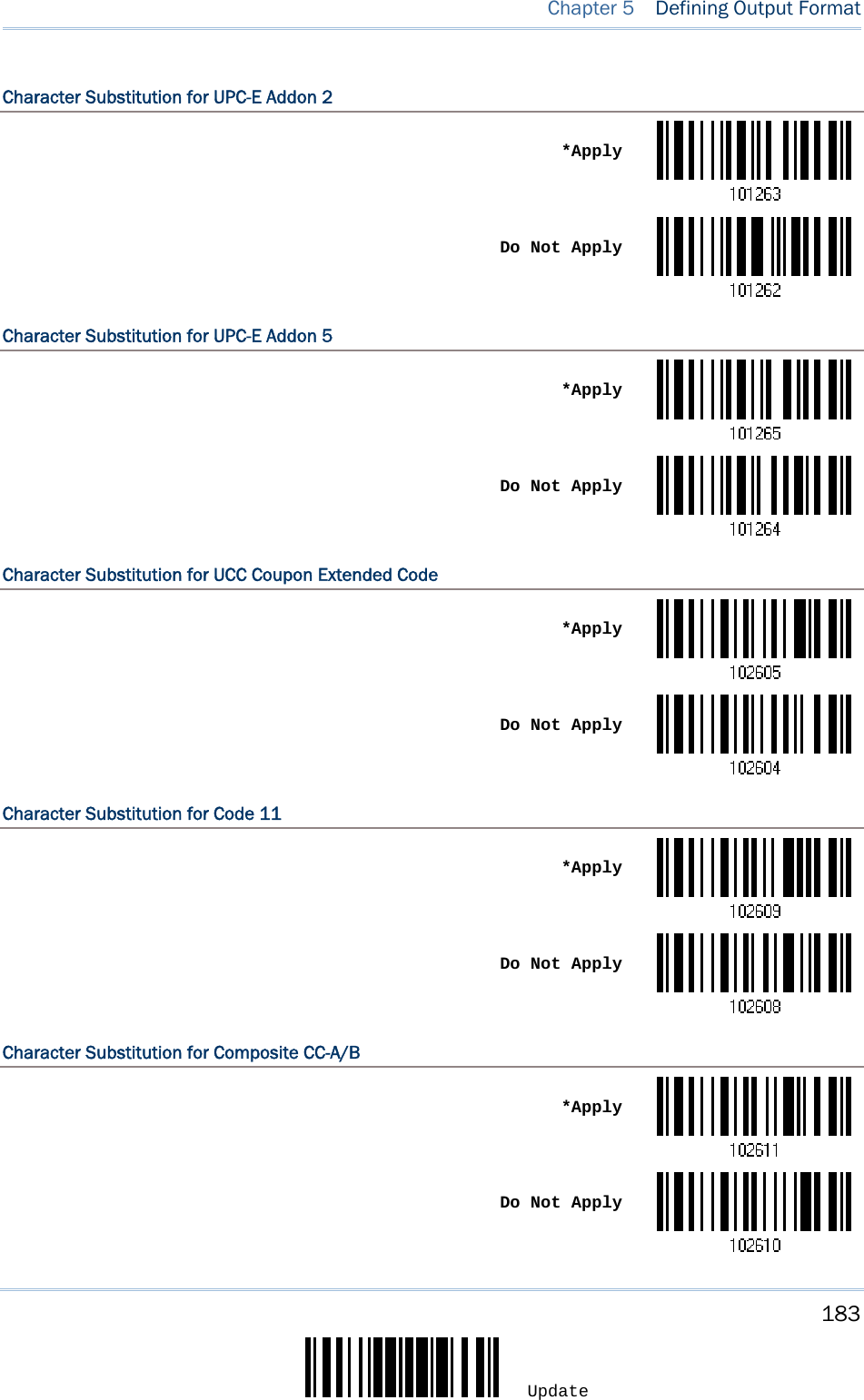
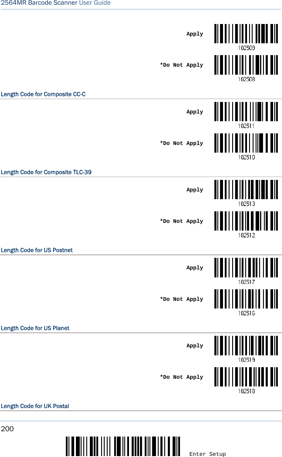
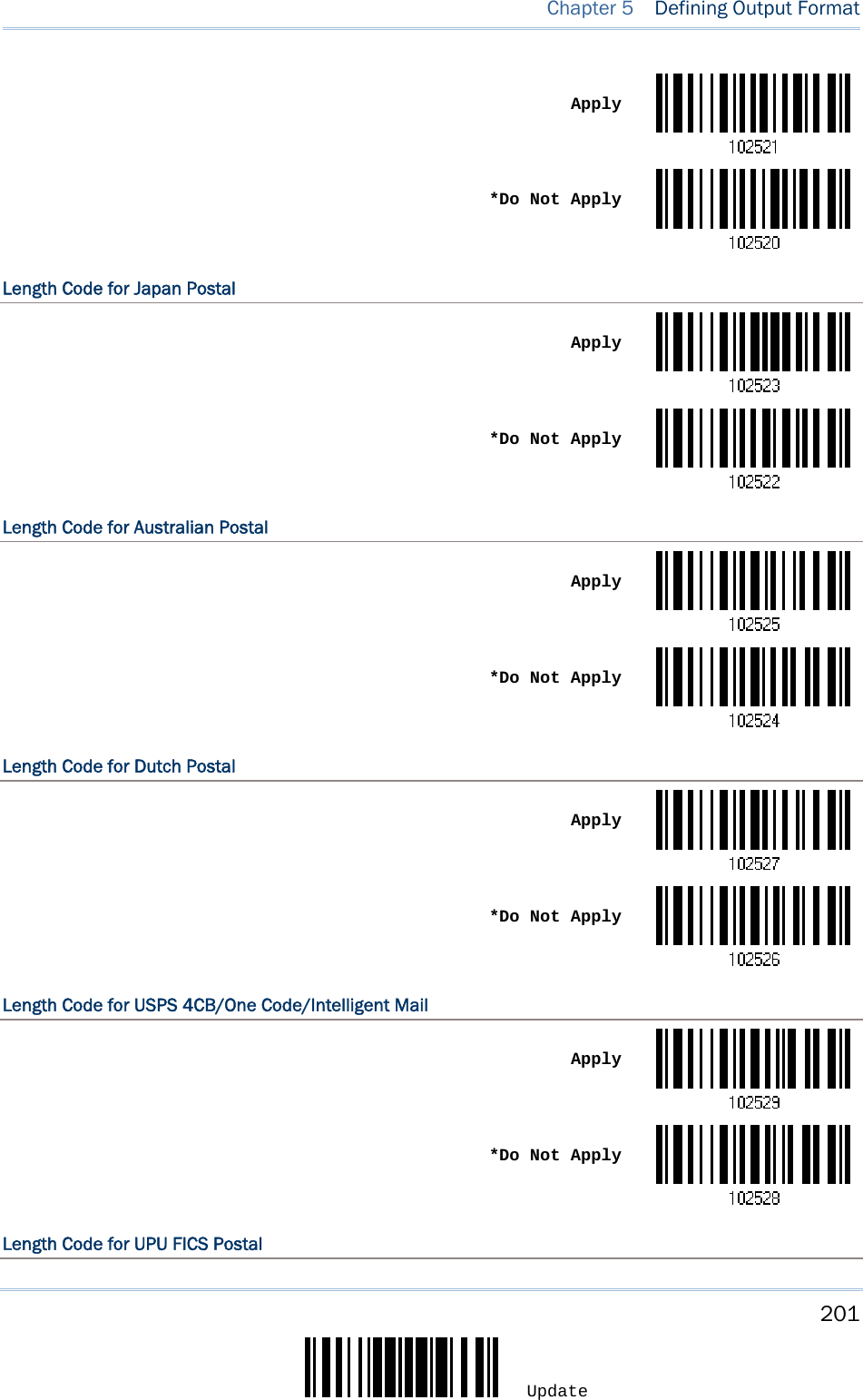
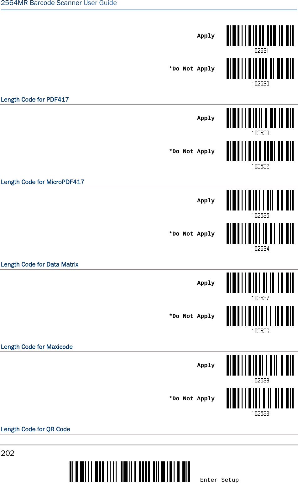
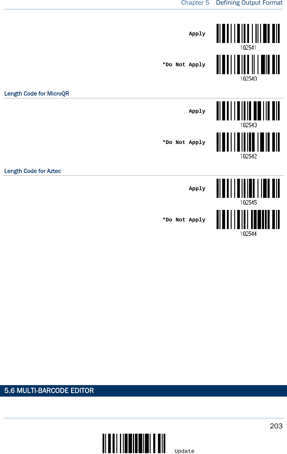
![175 Update You may configure in which format the collected data will be output to the host computer. Barcode read by the scanner will be processed in the following sequence – 1) Perform character substitution on the data scanned. 2) Add Code ID and Length Code to the front of the data:[Code ID][Length Code][Data] 3) Process the whole data in step 2 with user formats. Data is now divided into fields by user specified rules. Refer to Chapter 6 Applying Formats for Data Editing. 4) Add Prefix Code and Suffix Code before transmission:[Prefix Code][Processed Data][Suffix Code] IN THIS CHAPTER 5.1 Letter Case .............................................................. 175 5.2 Character Substitution ............................................... 176 5.3 Prefix/Suffix Code ..................................................... 188 5.4 Code ID ................................................................... 189 5.5 Length Code ............................................................ 196 5.6 Multi-Barcode Editor .................................................. 203 5.7 Removal of Special Character ..................................... 207 5.8 AIM Code ID ............................................................ 208 5.1 LETTER CASE By default, the alphabets transmission is case-sensitive, meaning that the alphabets will be transmitted according to their original case. Ignoring the original letter case, select [Upper Case] to output data in upper case only; otherwise, select [Lower Case] to output data in lower case only. *Normal Upper Case Lower Case Chapter 5 DEFINING OUTPUT FORMAT](https://usermanual.wiki/CipherLab/2564/User-Guide-3359037-Page-184.png)
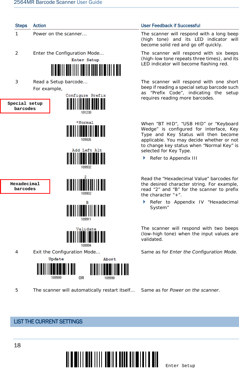
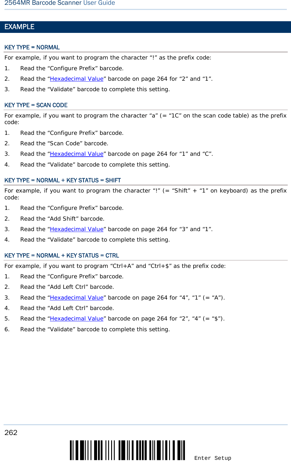
![188 Enter Setup 2564MR Barcode Scanner User Guide 5.3 PREFIX/SUFFIX CODE By default, there is no prefix code, and [ENTER] or [CR] (Carriage Return) is configured to be suffix code. Up to 8 characters can be configured, for example, “Barcode_”, and you will have the string appear in front of the barcode read, like this – “Barcode_1234567890”. If “BT HID”, “USB HID” or “Keyboard Wedge” is configured for interface, Key Type and Key Status will then become applicable. You may decide whether or not to apply Key Status when “Normal Key” is selected for Key Type. Key Type Key Status Scan Code Up to 4 scan code values are allowed. N/A Normal Key Up to 8 character strings are allowed. Add Shift Add Left Ctrl Add Left Alt Add Right Ctrl Add Right Alt Refer to Keyboard Wedge Table. Configure Prefix Configure Suffix1) Read the barcode above to apply prefix code or suffix code separately, and follow steps 2~3. (Max. 8 characters each) 2) Read the “Hexadecimal Value” barcode on page 264 for the desired character string. For example, read “2” and “B” for the scanner to prefix or suffix the character [+]. 3) Read the “Validate” barcode to complete this setting.](https://usermanual.wiki/CipherLab/2564/User-Guide-3359037-Page-197.png)
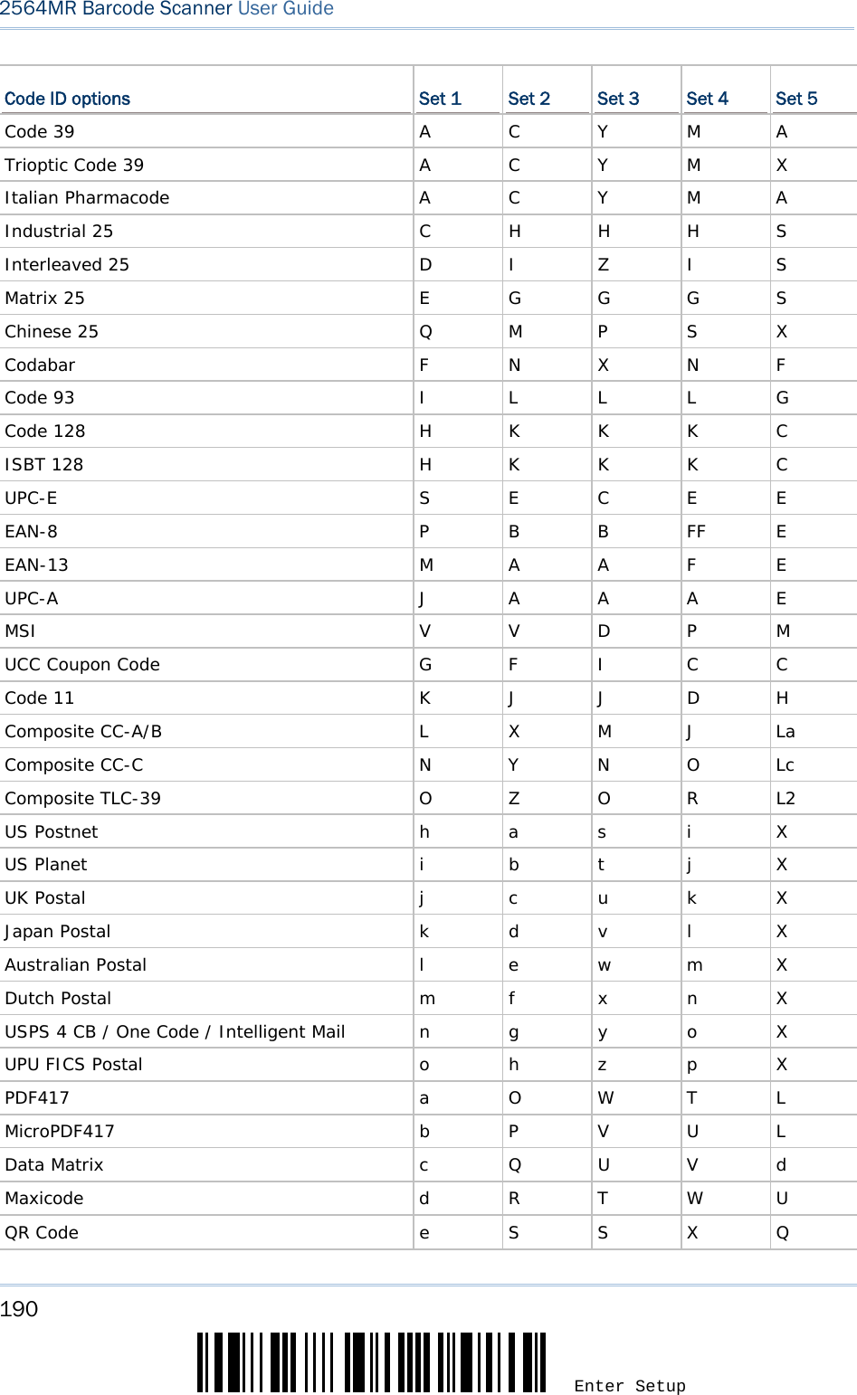
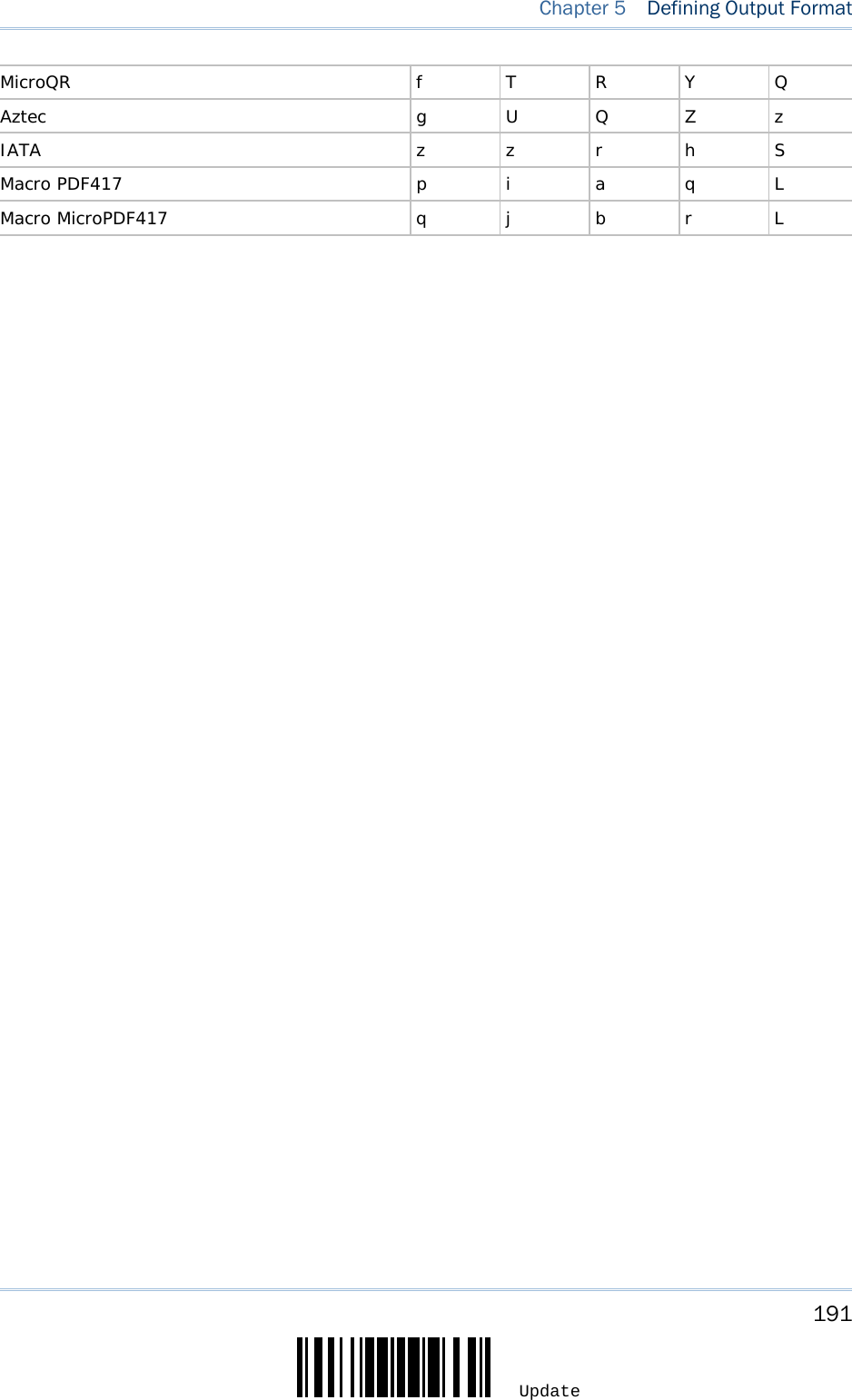
![189 Update Chapter 5 Defining Output Format 5.4 CODE ID Up to two characters for Code ID can be configured for each symbology. To make the Code ID configuration easier, the scanner provides five pre-defined Code ID sets that you can select one and make necessary changes on it. If “BT HID”, “USB HID” or “Keyboard Wedge” is configured for interface, Key Type and Key Status will then become applicable. You may decide whether or not to apply Key Status when “Normal Key” is selected for Key Type. Key Type Key Status Scan Code Only 1 scan code value is allowed. N/A Normal Key Up to 2 character strings are allowed. Add Shift Add Left Ctrl Add Left Alt Add Right Ctrl Add Right Alt Refer to Keyboard Wedge Table. Note: "]C1" is the Code ID of GS1-128 (EAN-128) barcodes; "]e0" is the default Code ID of GS1 DataBar (RSS) barcodes. 5.4.1 SELECT PRE-DEFINED CODE ID Apply Code ID Set 1 Apply Code ID Set 2 Apply Code ID Set 3 Apply Code ID Set 4 Apply Code ID Set 5](https://usermanual.wiki/CipherLab/2564/User-Guide-3359037-Page-198.png)
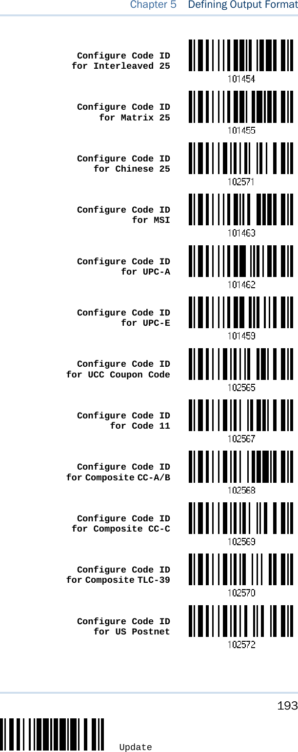
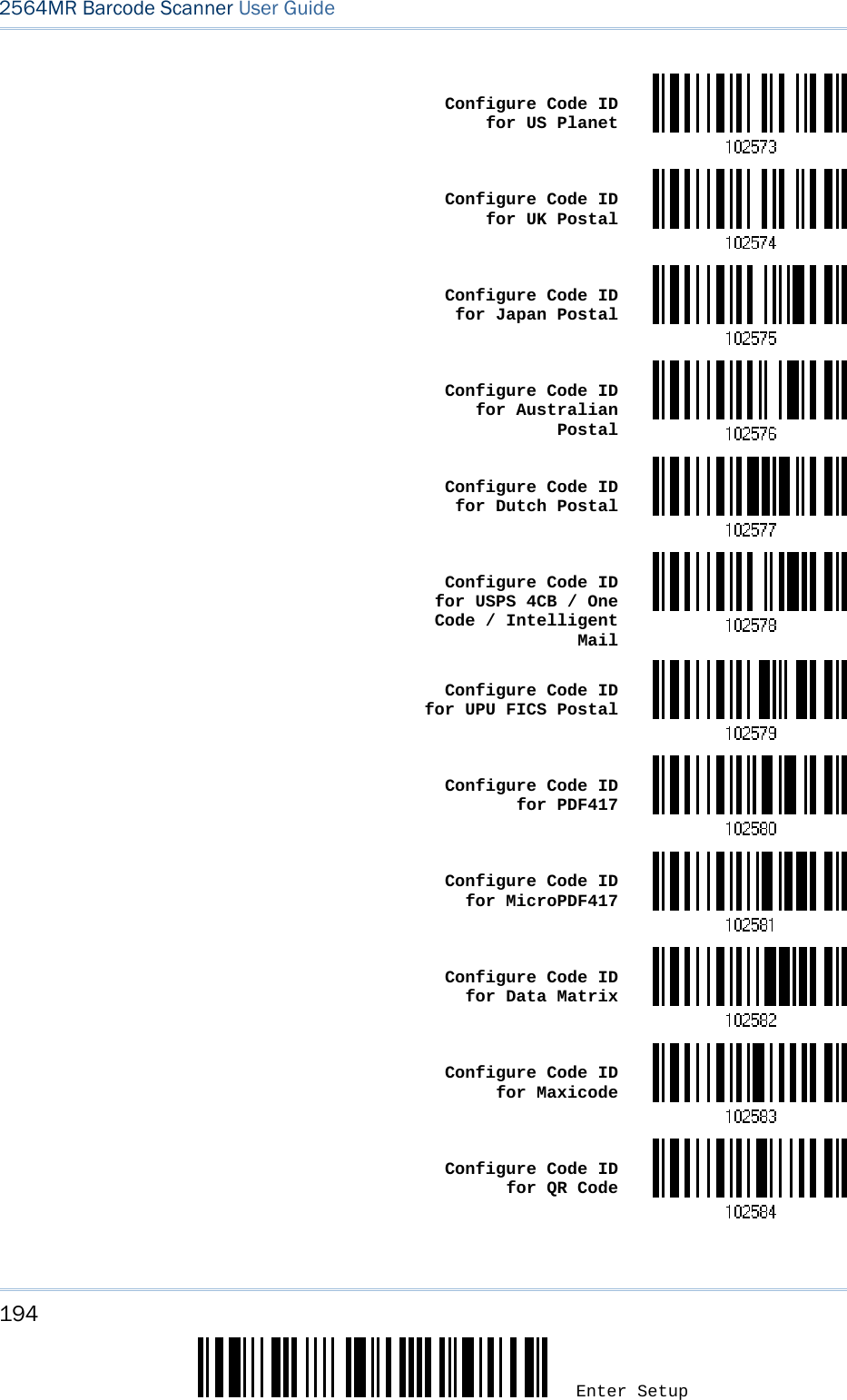
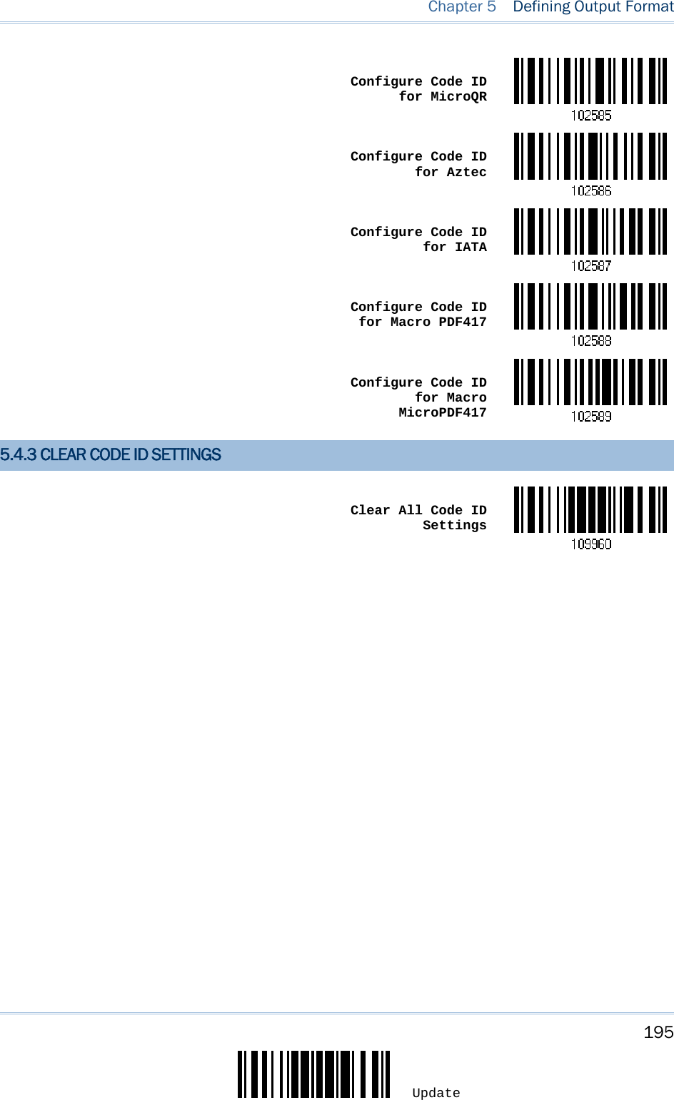
![192 Enter Setup 2564MR Barcode Scanner User Guide 5.4.2 CHANGE CODE ID 1) Read the barcode below to change code ID of a specific symbology. 2) Read the “Hexadecimal Value” barcode on page 264 for the desired character string. For example, read “4” and “4” for applying the character [D] for Code ID. 3) Read the “Validate” barcode to complete this setting. Configure Code ID for Codabar Configure Code ID for Code 39 Configure Code ID for Trioptic Code 39 Configure Code ID for Code 93 Configure Code ID for Code 128 Configure Code ID for ISBT 128 Configure Code ID for EAN-8 Configure Code ID for EAN-13 Configure Code ID for Italian Pharmacode Configure Code ID for Industrial 25](https://usermanual.wiki/CipherLab/2564/User-Guide-3359037-Page-201.png)


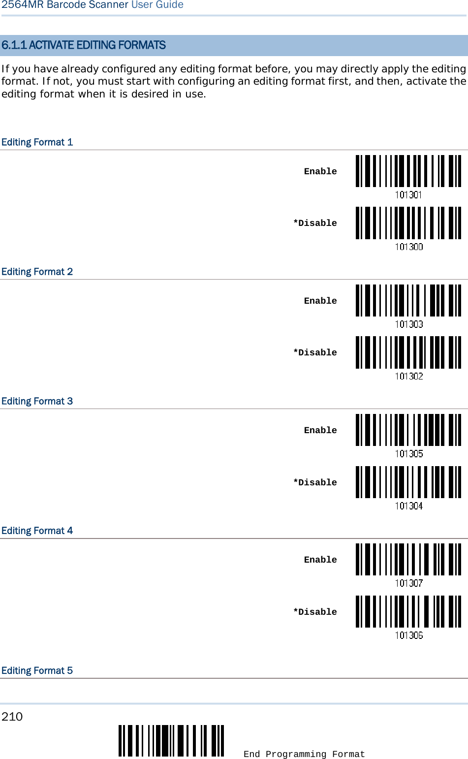
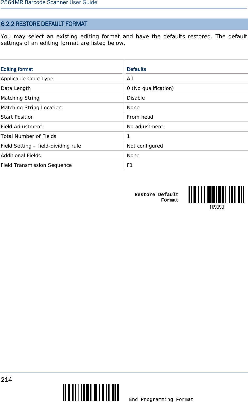
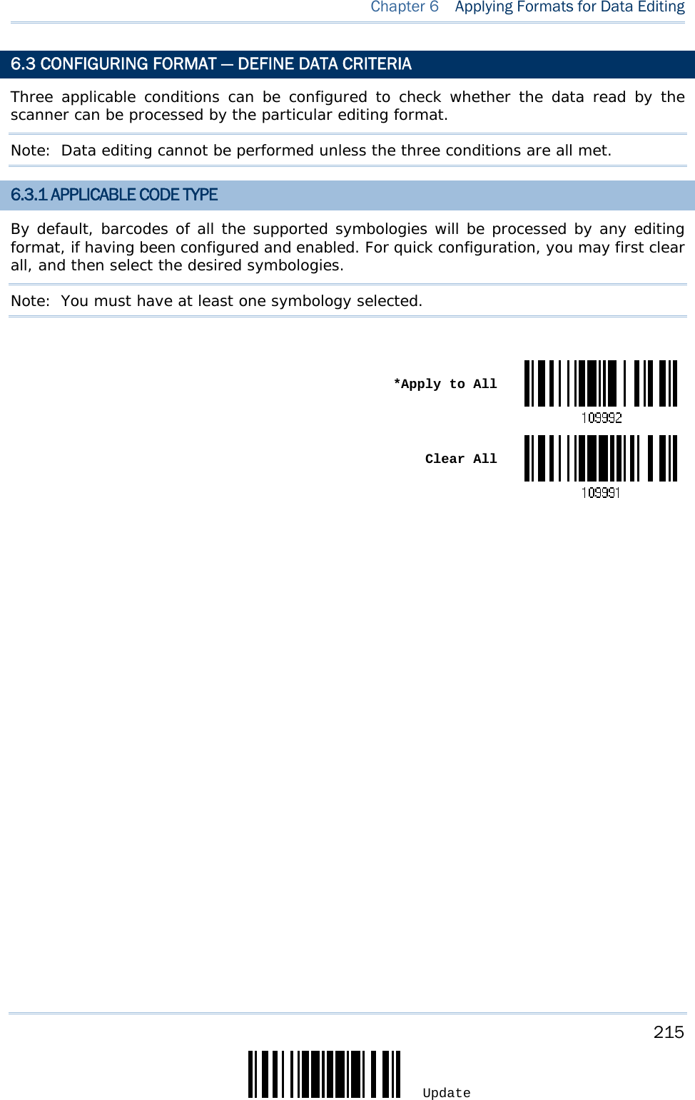
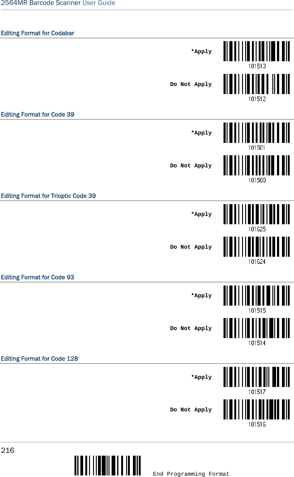
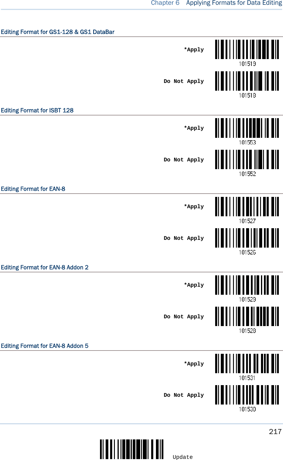
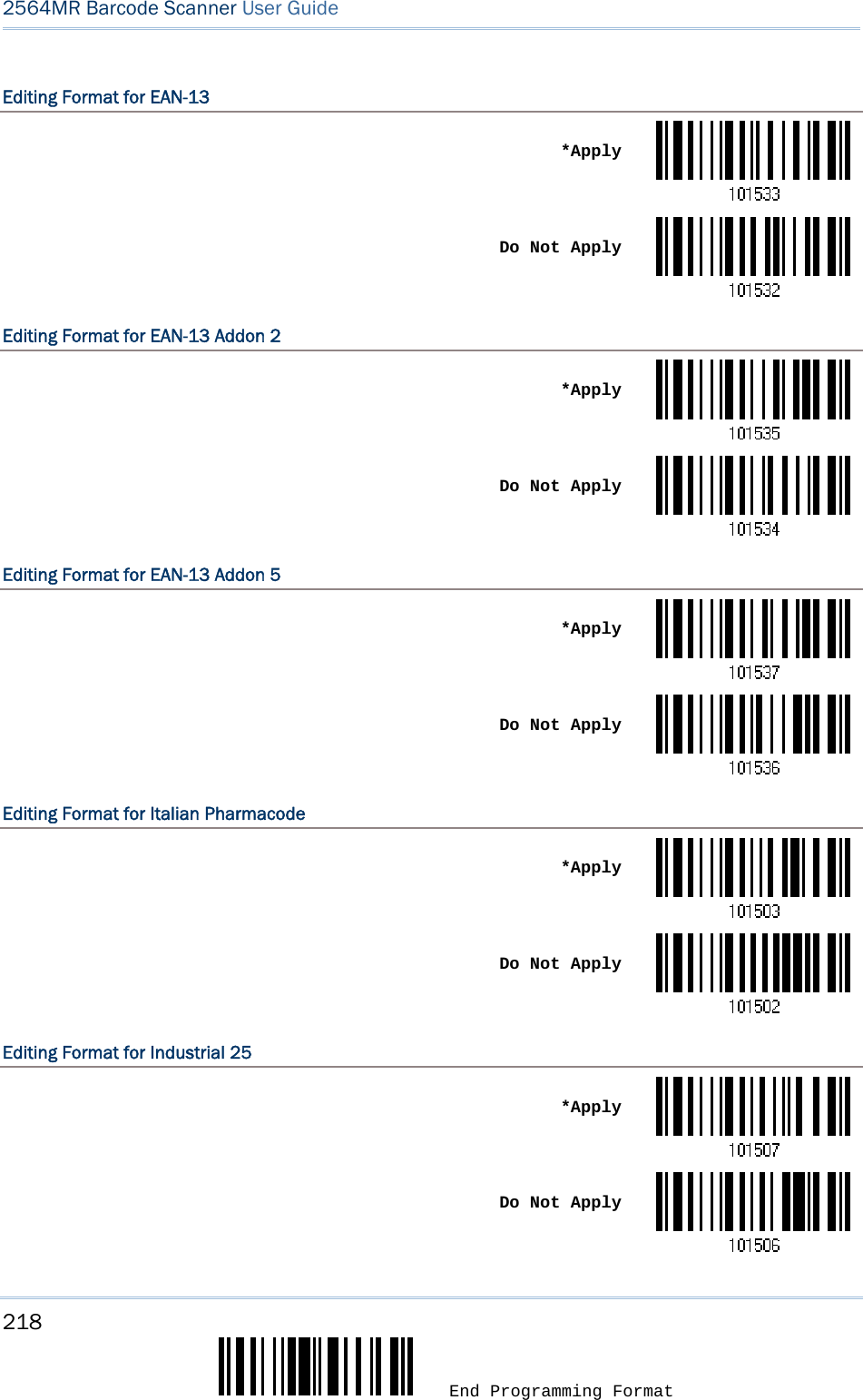
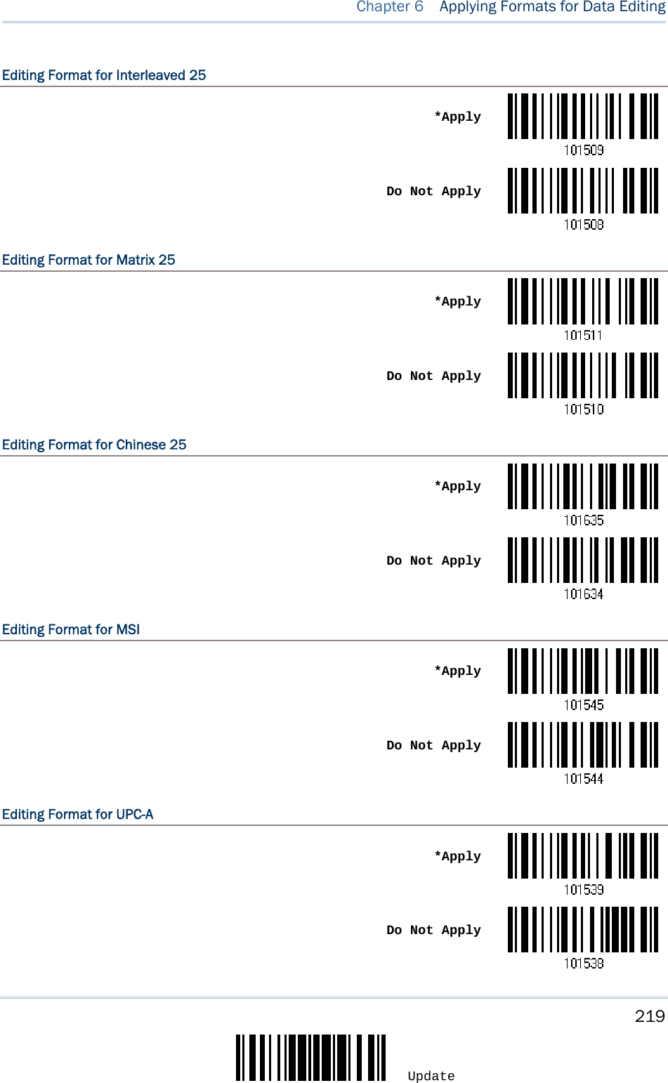
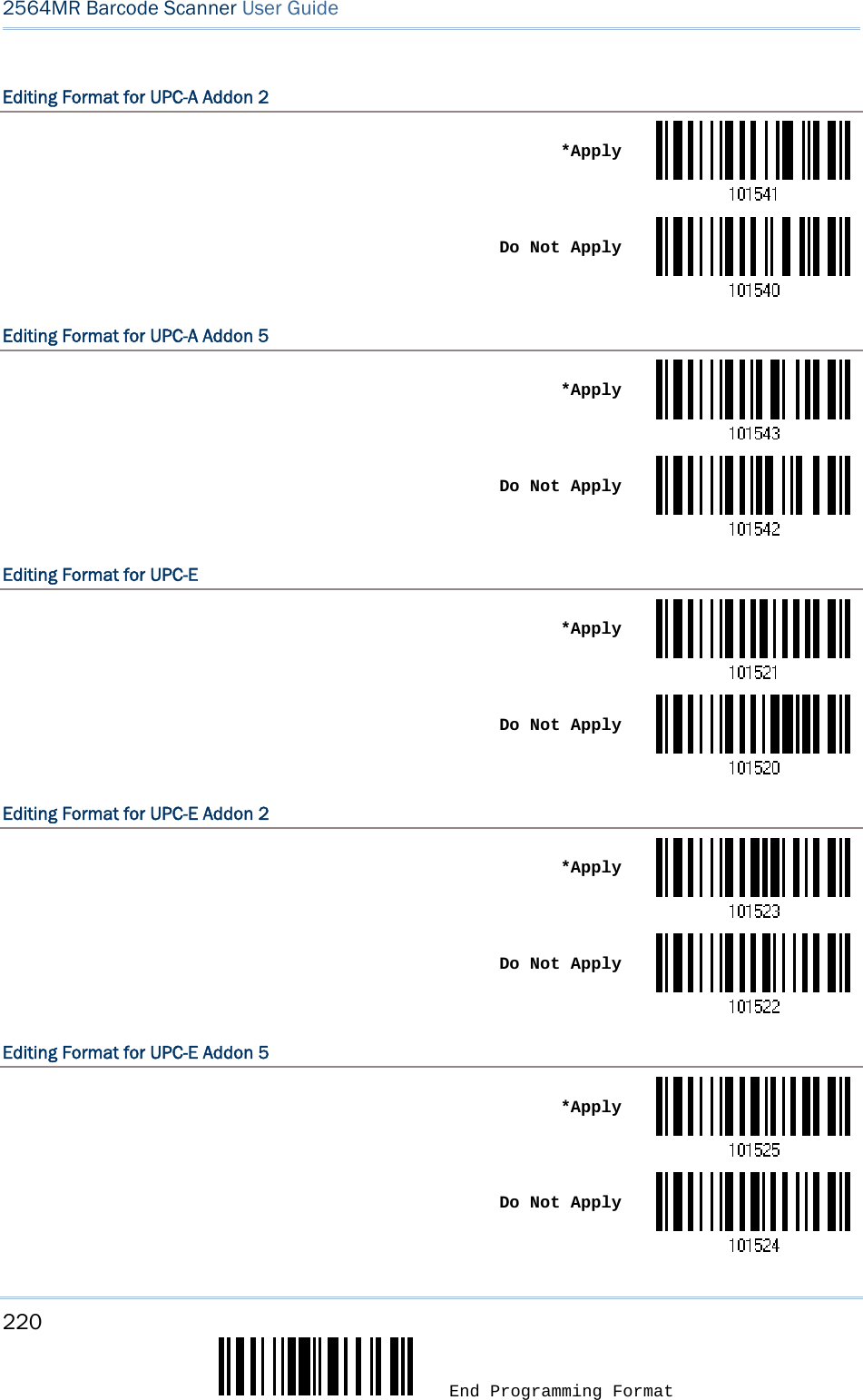
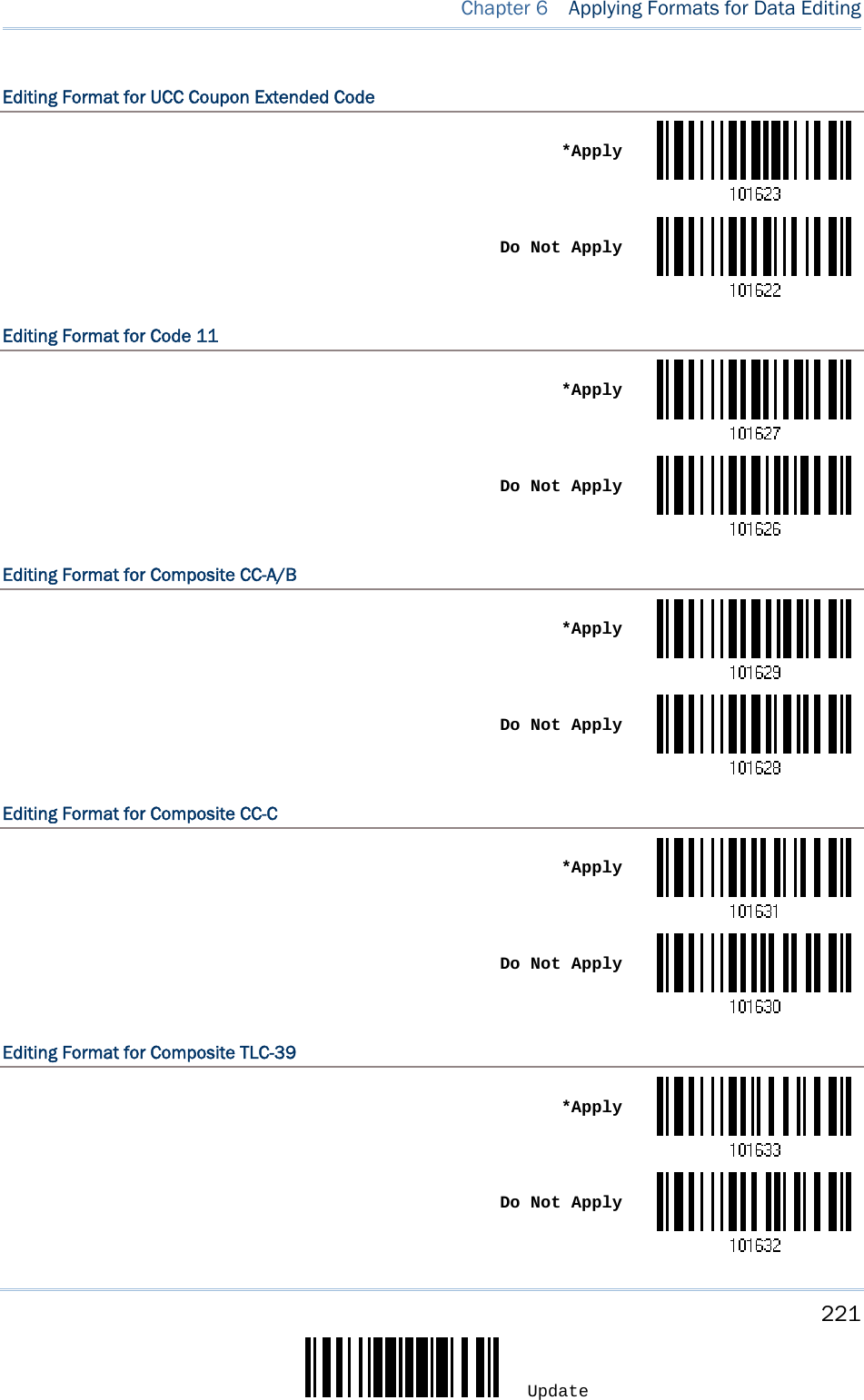
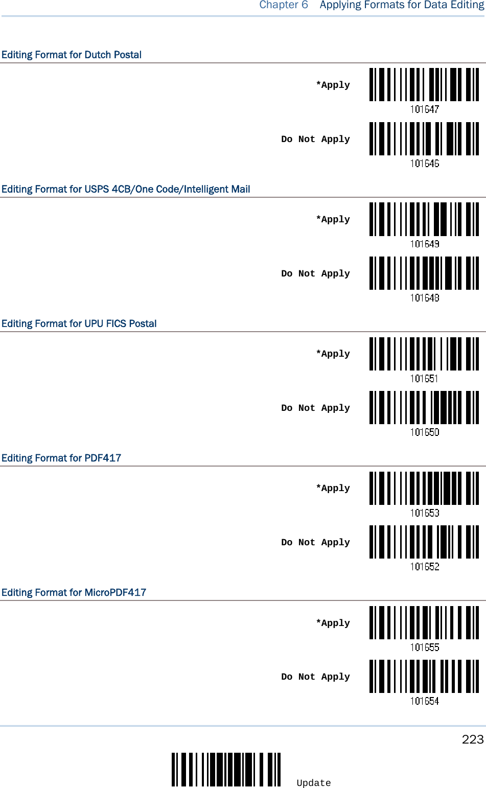
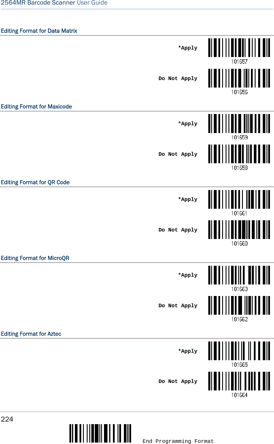
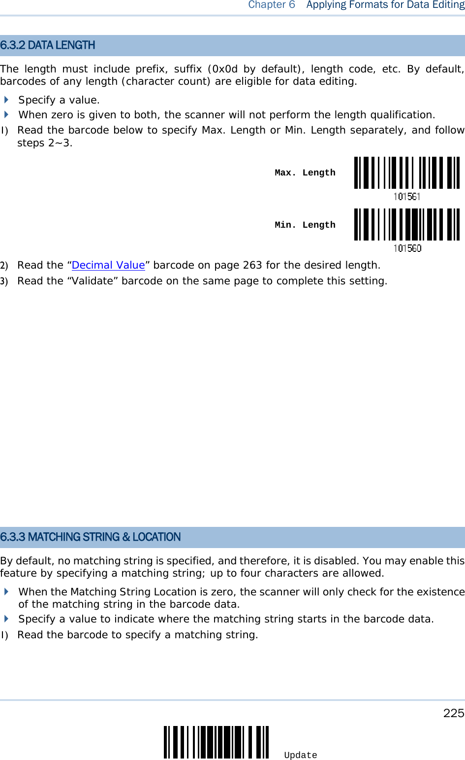
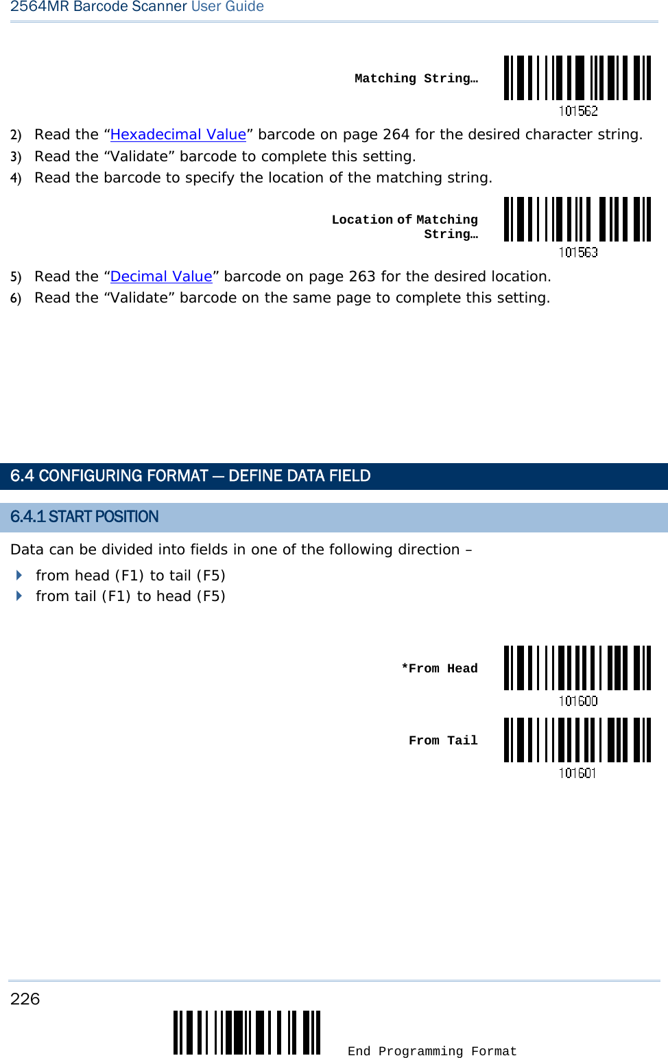
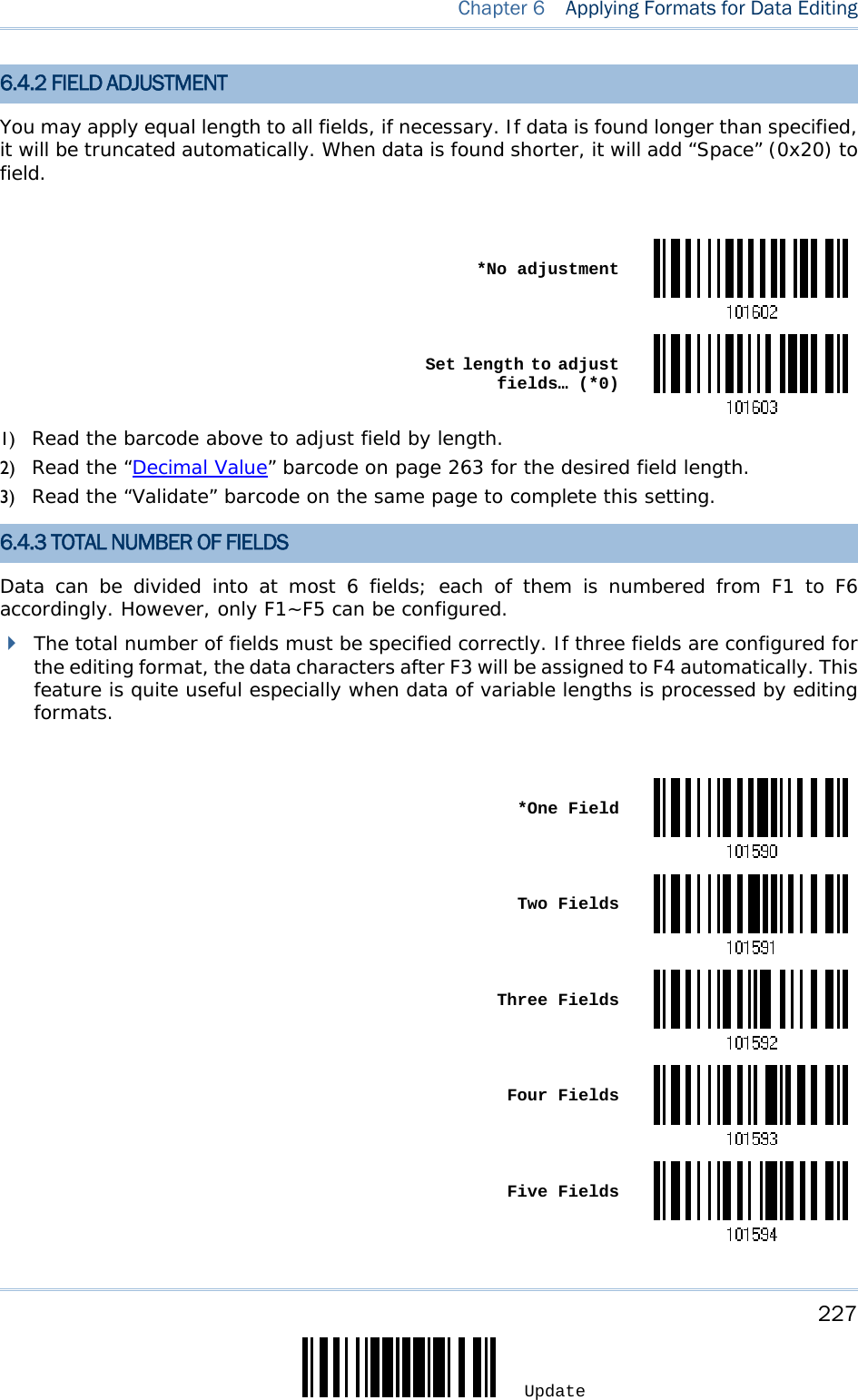
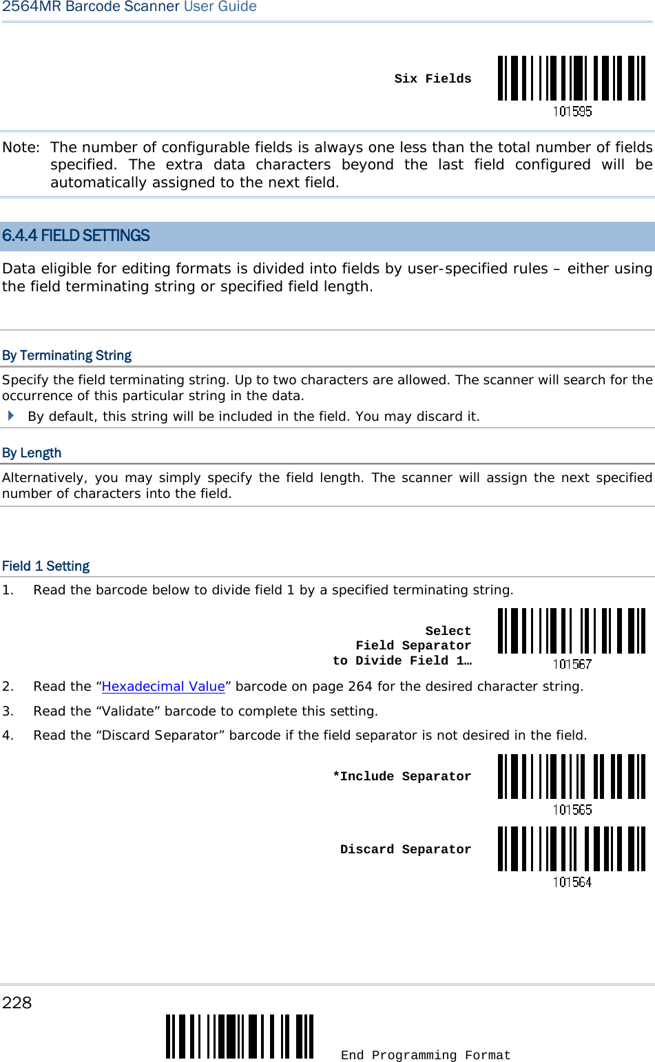
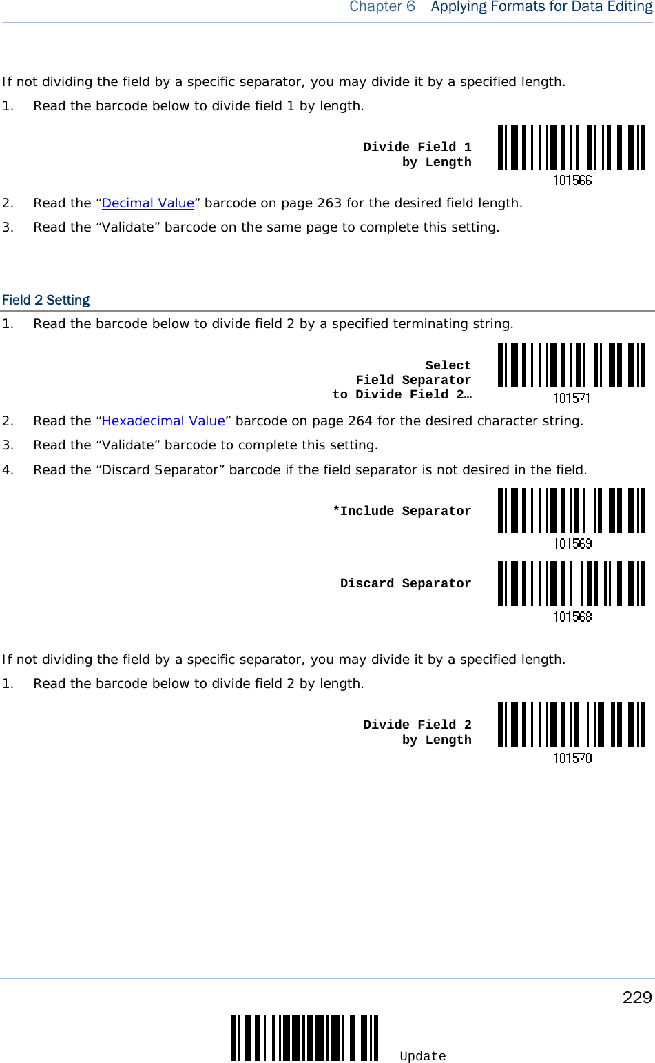
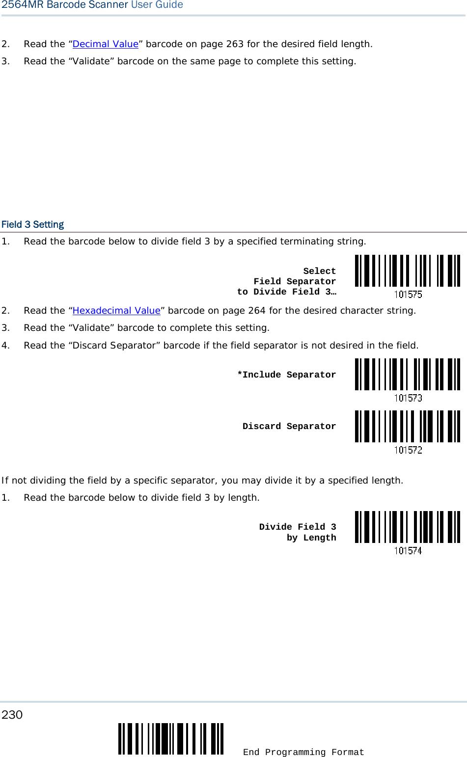
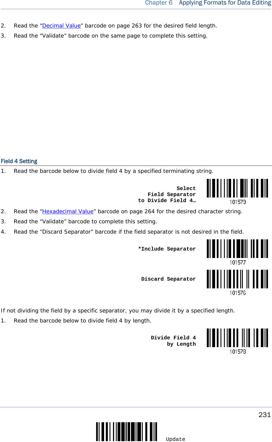
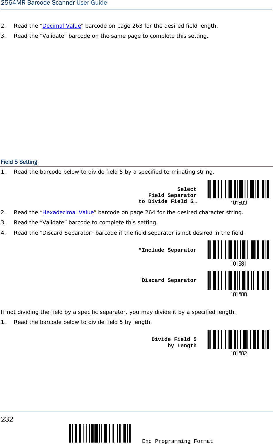
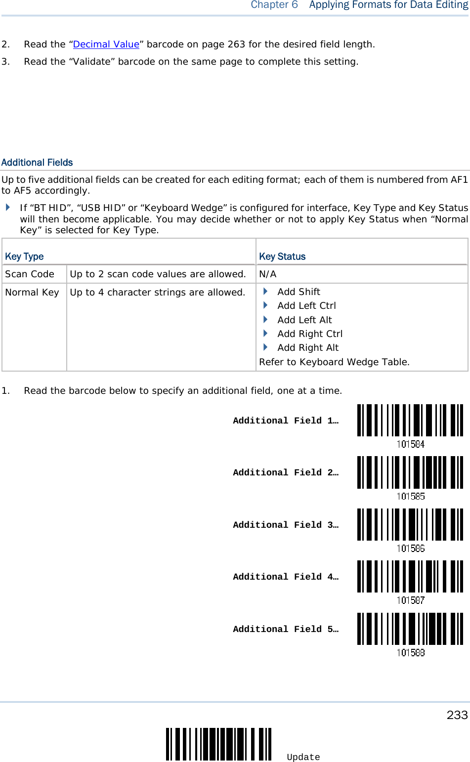
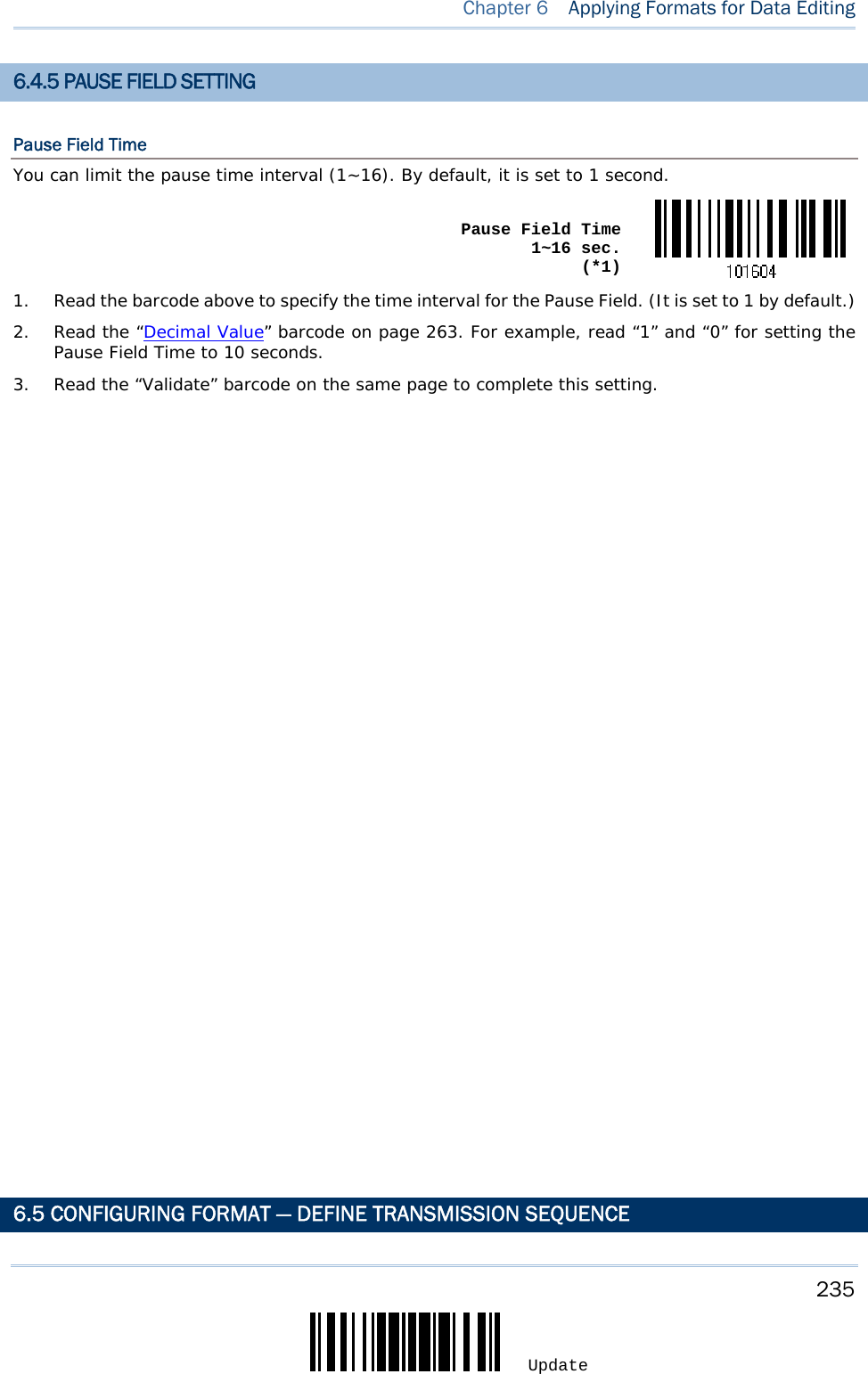
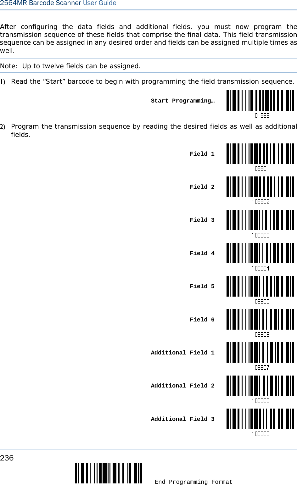
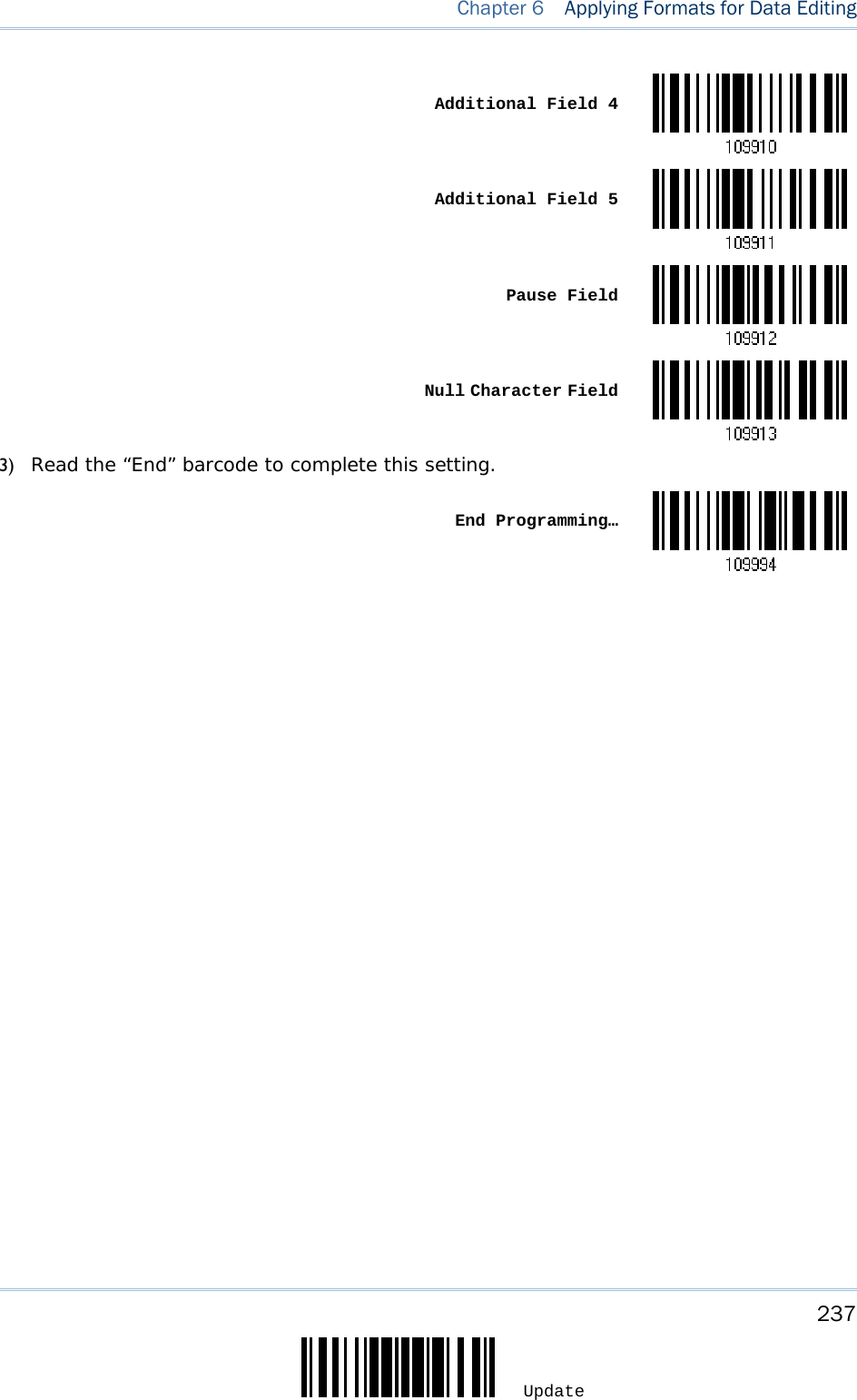
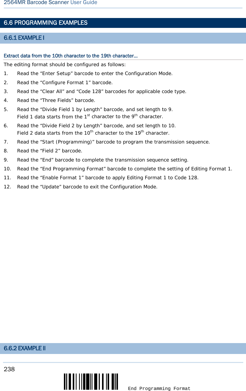
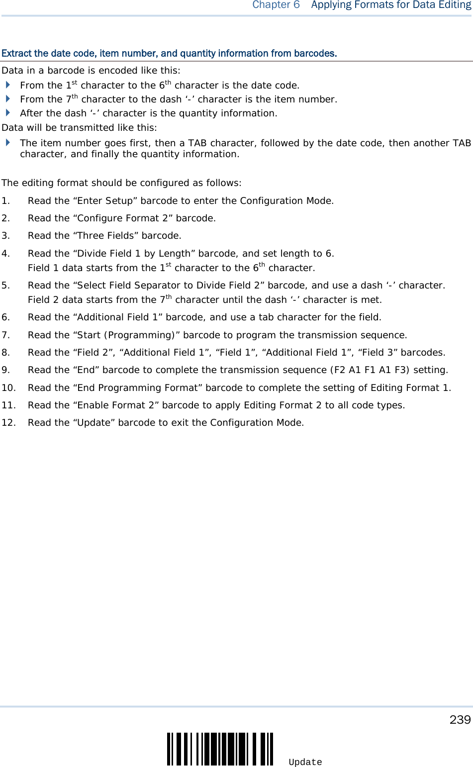
![209 Update The scanner allows advanced data editing by applying user-configured editing formats. The whole processed data can be divided into fields by user-specified rules. These fields together with the user-configurable additional fields comprise the data actually sent to the host computer. With the editing format applied, the maximum output data length of a barcode is 7 KB after configuration. If the data length exceeds 7 KB, editing format will not take effect. [Prefix Code] [Code ID] [Length Code] [Data] [Suffix Code] Additional Field(s) None by default None by default None by default Barcode itself 0x0d by default IN THIS CHAPTER 6.1 Activating Editing Formats .......................................... 209 6.2 How to Configure Editing Formats ............................... 211 6.3 Configuring Format — Define Data Criteria ................... 215 6.4 Configuring Format — Define Data Field ....................... 226 6.5 Configuring Format — Define Transmission Sequence .... 235 6.6 Programming Examples ............................................. 238 6.1 ACTIVATING EDITING FORMATS Chapter 6 APPLYING FORMATS FOR DATA EDITING](https://usermanual.wiki/CipherLab/2564/User-Guide-3359037-Page-218.png)

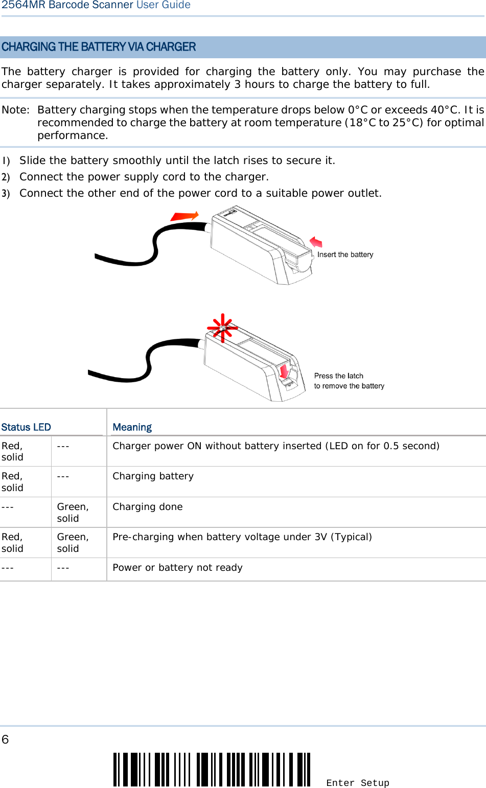
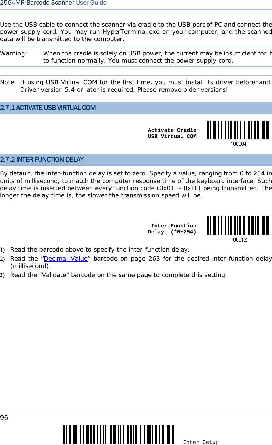
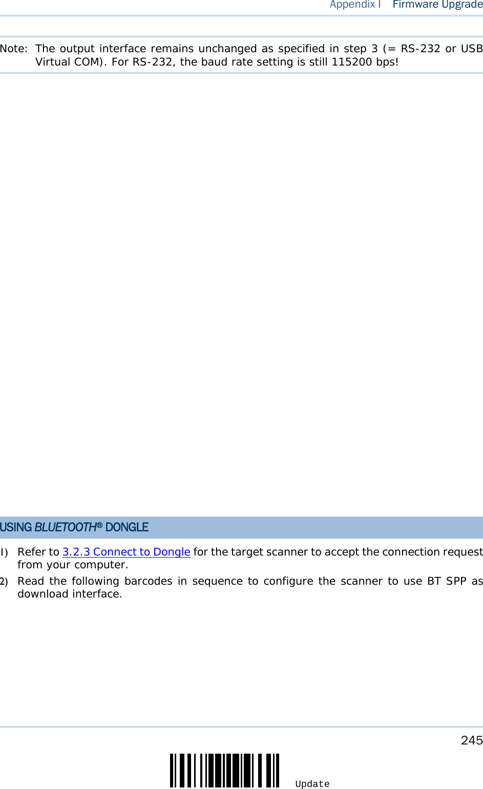
![244 Enter Setup 2564MR Barcode Scanner User Guide Enter Setup Activate Cradle USB Virtual COM Update5) Read the following barcodes in sequence for the scanner to enter the download mode. The scanner will respond with beeps to indicate it is ready for downloading. Enter Setup Download6) Run the download utility “ProgLoad.exe” on your computer. Kernel Program User Program K2564_V*.shx STD2564_V*.shx For the communication settings, select “RS-232” and the correct COM port for RS-232 or USB Virtual COM interface. For RS-232, select 115200 bps for baud rate; for USB Virtual COM, ignore the baud rate setting. For the file option, click [Browse] to select the target file for firmware update. Click [OK]. 7) After upgrading kernel, you will need to manually restart the scanner. After upgrading the user program, the scanner will automatically restart itself once the download is completed successfully.](https://usermanual.wiki/CipherLab/2564/User-Guide-3359037-Page-252.png)
![246 Enter Setup 2564MR Barcode Scanner User Guide Enter Setup Activate BT SPP Update3) Read the following barcodes in sequence for the scanner to enter the download mode. The scanner will respond with beeps to indicate it is ready for downloading. Enter Setup Download4) Run the download utility “ProgLoad.exe” on your computer. Kernel Program User Program K2564_V*.shx STD2564_V*.shx For the communication settings, select “RS-232” and the correct COM port for BT SPP interface. Ignore the baud rate setting. For the file option, click [Browse] to select the target file for firmware update. Click [OK]. 5) After upgrading kernel, you will need to manually restart the scanner. After upgrading the user program, the scanner will automatically restart itself once the download is completed successfully.](https://usermanual.wiki/CipherLab/2564/User-Guide-3359037-Page-254.png)
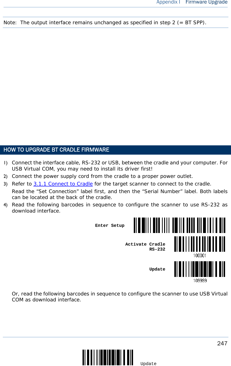
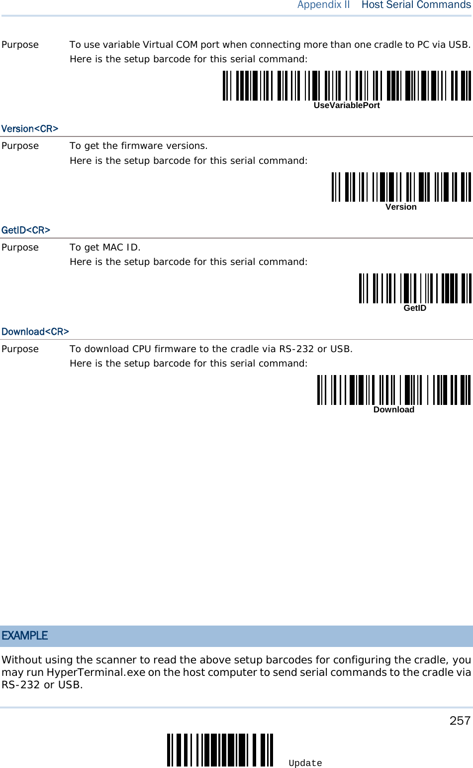
![248 Enter Setup 2564MR Barcode Scanner User Guide Enter Setup Activate Cradle USB Virtual COM Update5) Read the following barcodes in sequence for the cradle to enter the download mode. The Communication LED on the cradle will be flashing red to indicate it is ready for downloading. Enter Setup Download Cradle CPU Firmware 6) Run the download utility “ProgLoad.exe” on your computer. Kernel Program User Program 2560CradleKV*.shx 2560CradleUV*.shx For the communication settings, select “RS-232” and the correct COM port for RS-232 or USB Virtual COM interface. For RS-232, select 115200 bps for baud rate; for USB Virtual COM, ignore the baud rate setting. For the file option, click [Browse] to select the target file for firmware update. Click [OK]. 7) The cradle will automatically restart itself when upgrading firmware is completed successfully. 8) Read the “Update” barcode for the scanner to resume its operation (exit the configuration mode).](https://usermanual.wiki/CipherLab/2564/User-Guide-3359037-Page-256.png)
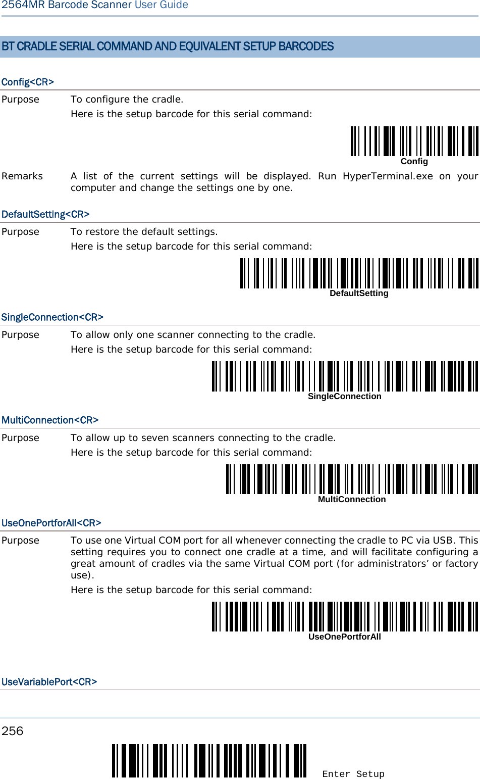
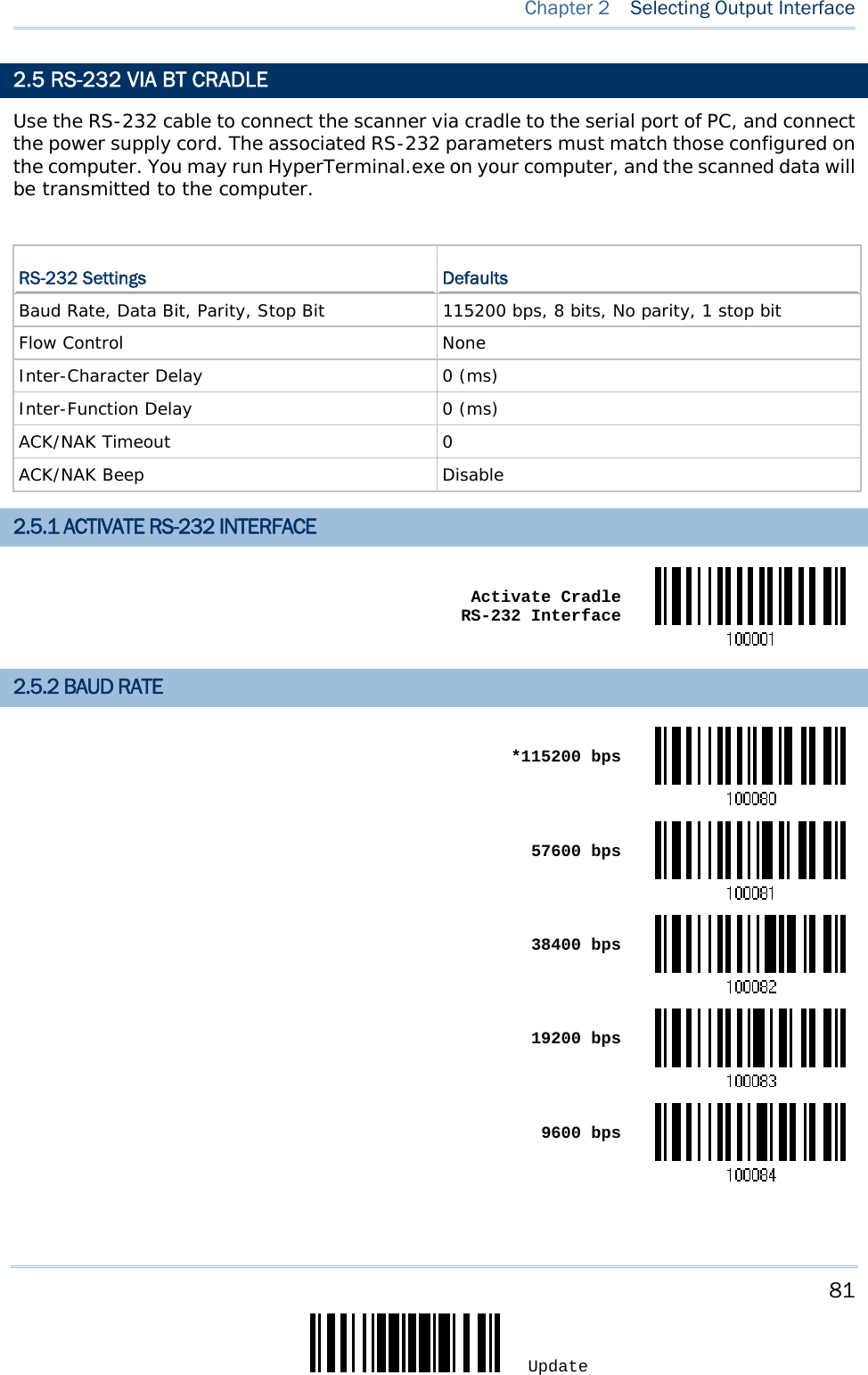
![258 Enter Setup 2564MR Barcode Scanner User Guide 1) Connect the interface cable, RS-232 or USB, between the cradle and your computer. For USB Virtual COM, you may need to install its driver first! 2) Connect the power supply cord from the cradle to a proper power outlet. The Communication LED will indicate when the cradle can accept serial commands after initializing. Refer to the table below. If the output interface is USB Virtual COM or RS-232, run HyperTerminal.exe on your computer. While the Communication LED on the cradle is purple (red with flashing blue), type the serial command within three seconds. If the output interface is USB HID, press the “Num Lock” or “Caps Lock” key on your keyboard 5 times within 3 seconds while the Communication LED on the cradle is flashing red and blue. This will change the interface from USB HID to USB Virtual COM and the Communication LED will become purple (red with flashing blue). Then, run HyperTerminal.exe on your computer. While the Communication LED on the cradle is purple (red with flashing blue), type the serial command within three seconds. After configuring via serial commands, the interface will be reset to USB HID after re-connecting the power supply cord. Communication LED Meaning --- Blue, solid Initialize Red, solid Blue, flashing Serial command mode with USB Virtual COM or RS-232: wait 3 seconds for starting a serial command Red, flashing Blue, flashing Serial command mode with USB HID changed to USB Virtual COM first: wait 3 seconds for pressing [Num Lock] or [Caps Lock] 5 times via keyboard](https://usermanual.wiki/CipherLab/2564/User-Guide-3359037-Page-266.png)
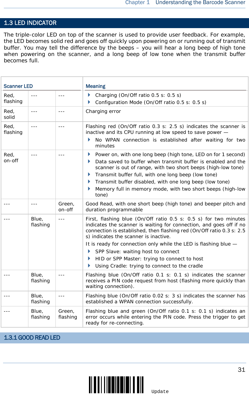
![259 Update The table below features special keyboard wedge codes applied to the scanner by default. If you have determined to bypass this special keyboard, please refer to the table on the next page. “Apply” Special Keyboard 0 1 2 3 4 5 6 7 8 0 F2 SP 0 @ P ` p 1 INS F3 ! 1 A Q a q 2 DLT F4 " 2 B R b r 3 Home F5 # 3 C S c s 4 End F6 $ 4 D T d t 5 Up F7 % 5 E U e u 6 Down F8 & 6 F V f v 7 Left F9 ' 7 G W g w 8 BS F10 ( 8 H X h x 9 HT F11 ) 9 I Y i y A LF F12 * : J Z j z B Right ESC + ; K [ k { C PgUp Exec , < L \ l | D CR CR* - = M ] m } E PgDn . > N ^ n ~ F F1 / ? O _ o Dly ENTER* Note: (1) ~: Digits of numeric keypad. (2) CR*/ENTER*: ENTER key on the numeric keypad. “Bypass” Special Keyboard 0 1 2 3 4 5 6 7 8 Appendix III KEYBOARD WEDGE TABLE](https://usermanual.wiki/CipherLab/2564/User-Guide-3359037-Page-267.png)
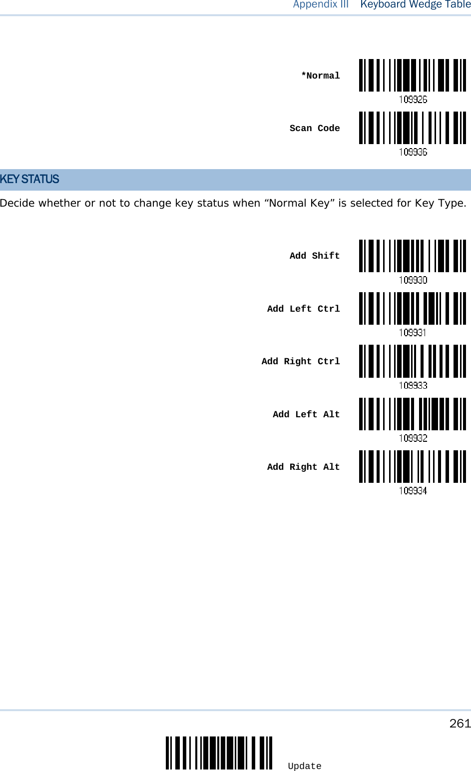
![260 Enter Setup 2564MR Barcode Scanner User Guide “Bypass” Special Keyboard 0 1 2 3 4 5 6 7 8 0 SP 0 @ P ` p 1 ! 1 A Q a q 2 " 2 B R b r 3 # 3 C S c s 4 $ 4 D T d t 5 % 5 E U e u 6 & 6 F V f v 7 ' 7 G W g w 8 BS ( 8 H X h x 9 HT ) 9 I Y i y A LF * : J Z j z B ESC + ; K [ k { C , < L \ l | D CR - = M ] m } E . > N ^ n ~ F / ? O _ o Dly KEY TYPE & STATUS KEY TYPE If “BT HID”, “USB HID” or “Keyboard Wedge” is configured for interface, Key Type and Key Status will then become applicable.](https://usermanual.wiki/CipherLab/2564/User-Guide-3359037-Page-268.png)
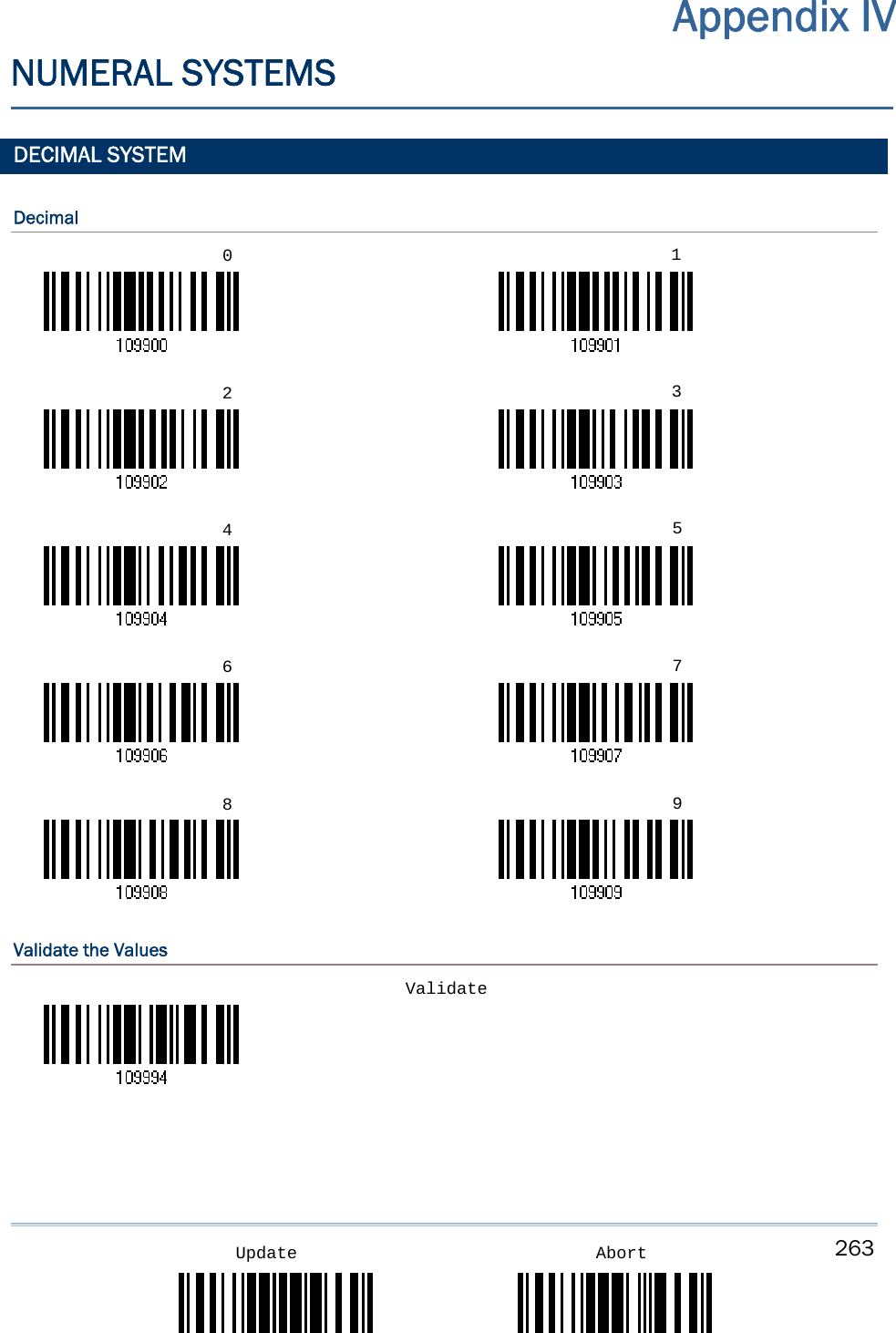
![265 Appendix IV Numeral Systems Update AbortValidate the Values ASCII TABLE 0 1 2 3 4 5 6 7 0 DLE SP 0 @ P ` p 1 SOH DC1 ! 1 A Q a q 2 STX DC2 " 2 B R b r 3 ETX DC3 # 3 C S c s 4 EOT DC4 $ 4 D T d t 5 ENQ NAK % 5 E U e u 6 ACK SYN & 6 F V f v 7 BEL ETB ' 7 G W g w 8 BS CAN ( 8 H X h x 9 HT EM ) 9 I Y i y A LF SUB * : J Z j z B VT ESC + ; K [ k { C FF FS , < L \ l | D CR GS - = M ] m } E SO RS . > N ^ n ~ F SI US / ? O _ o DEL Validate](https://usermanual.wiki/CipherLab/2564/User-Guide-3359037-Page-273.png)
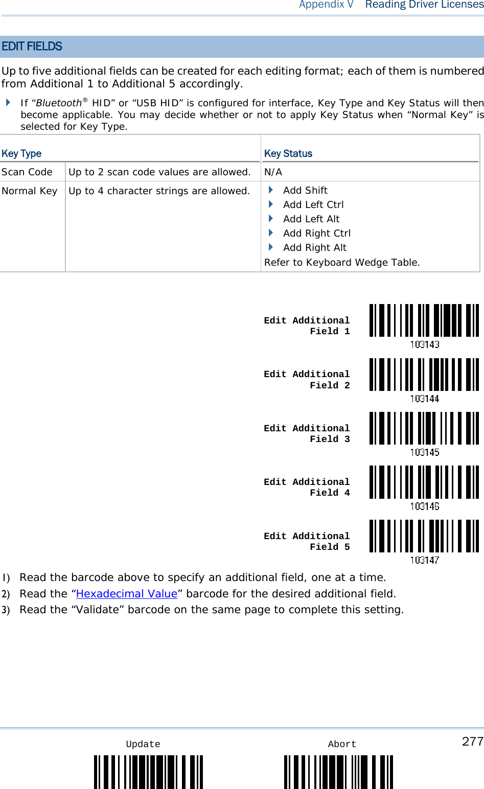
![276 Enter Setup 2564MR Barcode Scanner User Guide EDIT SEPARATORS All the driver license fields can be split with a pre-selected separator, for example, “-” as First Name-Last Name or “:” as First Name:Last Name. Edit Separator 1 Edit Separator 2 Edit Separator 3 Edit Separator 4 Edit Separator 51) Read the barcode above to apply separator to driver license information separately, and follow steps 2~3. 2) Read the “Hexadecimal Value” barcode for the desired character string. For example, read “3” and “A” for the separator to split the data with character [:]. 3) Read the “Validate” barcode on the same page to complete this setting.](https://usermanual.wiki/CipherLab/2564/User-Guide-3359037-Page-284.png)