CipherLab 3610 BT Transponder User Manual manual
CipherLab Co., Ltd. BT Transponder manual
UserManual.wiki
>
CipherLab
>
3610 User Manual
manual
Navigation menu
Upload a User Manual
Namespaces
Wiki Guide
HTML
PDF
Info
Views
User Manual
Discussion / Help
Navigation


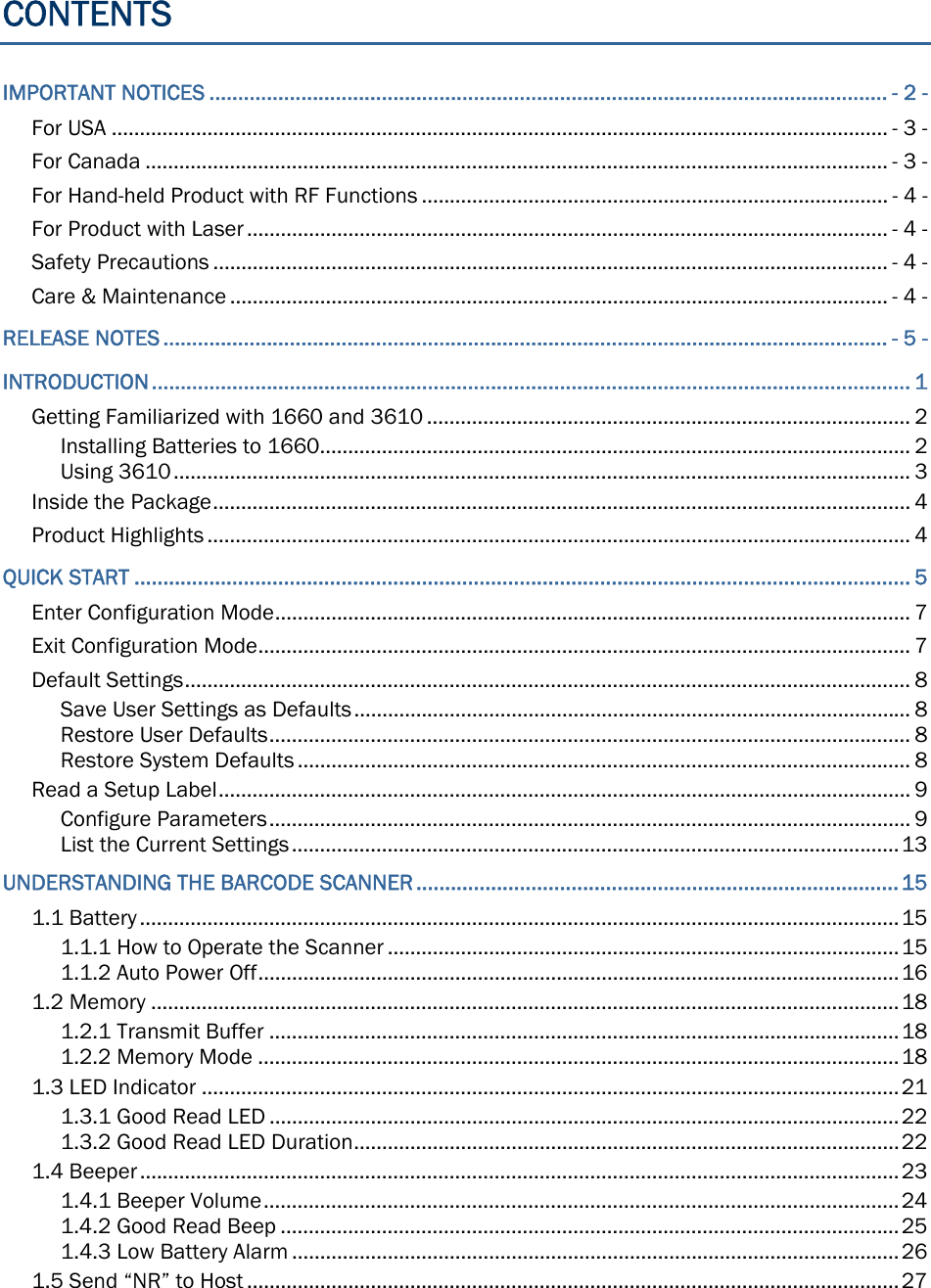

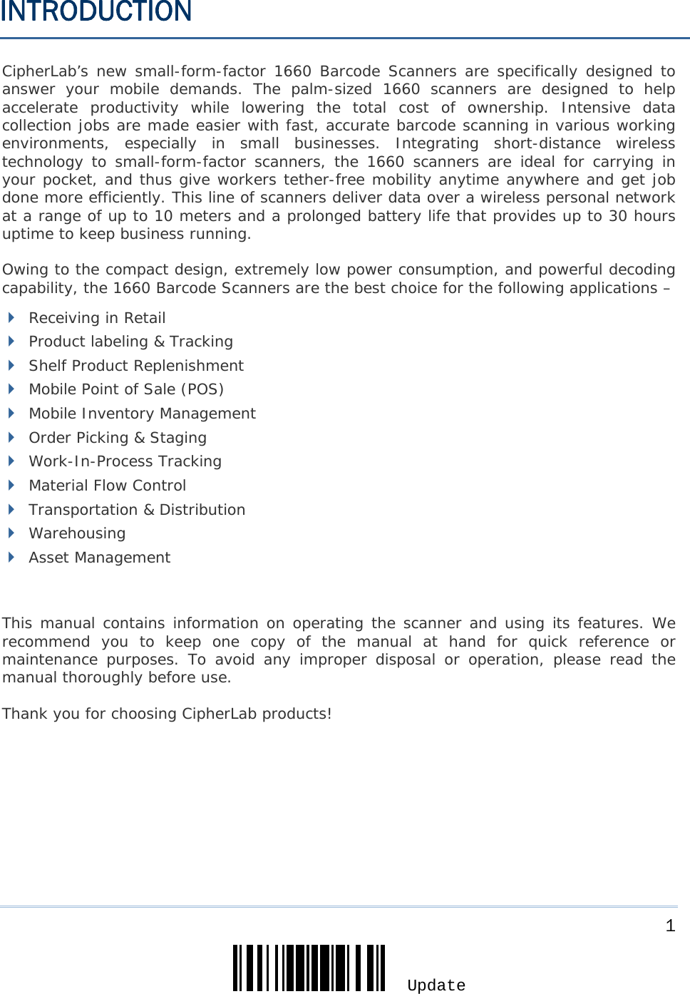
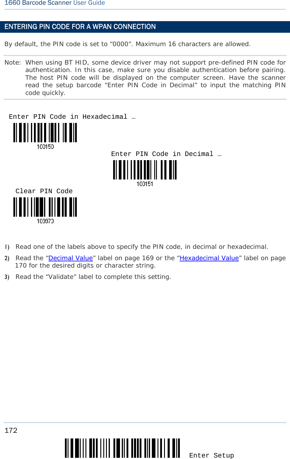
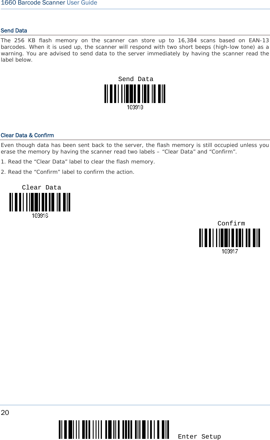
![2 Enter Setup 1660 Barcode Scanner User Guide GETTING FAMILIARIZED WITH 1660 AND 3610 INSTALLING BATTERIES TO 1660 1) Hold the scanner face down in one hand. 2) Press the battery lid release and slide the battery lid. 3) Remove the battery lid by the other hand. 4) Install two AAA Alkaline batteries into the battery compartment, each in the right direction. 5) Replace the battery lid and lock it firmly. 6) Press the [Power/Delete] key for 3 seconds to turn on 1660. The scanner will respond with a long beep (high tone) and its LED indicator will become solid red and go off quickly. Note: To turn off the scanner, press the [Power/Delete] key for 2 seconds. The scanner will respond with two short beeps (high tone) and the LED will finally become solid red. Release the key then. Otherwise, let the scanner turn off automatically in specific circumstances. Refer to settings of “Auto Power Off”. For shipping and storage purposes, save the scanner and the batteries separately. This will keep the batteries in good condition for future use.](https://usermanual.wiki/CipherLab/3610/User-Guide-1096354-Page-14.png)
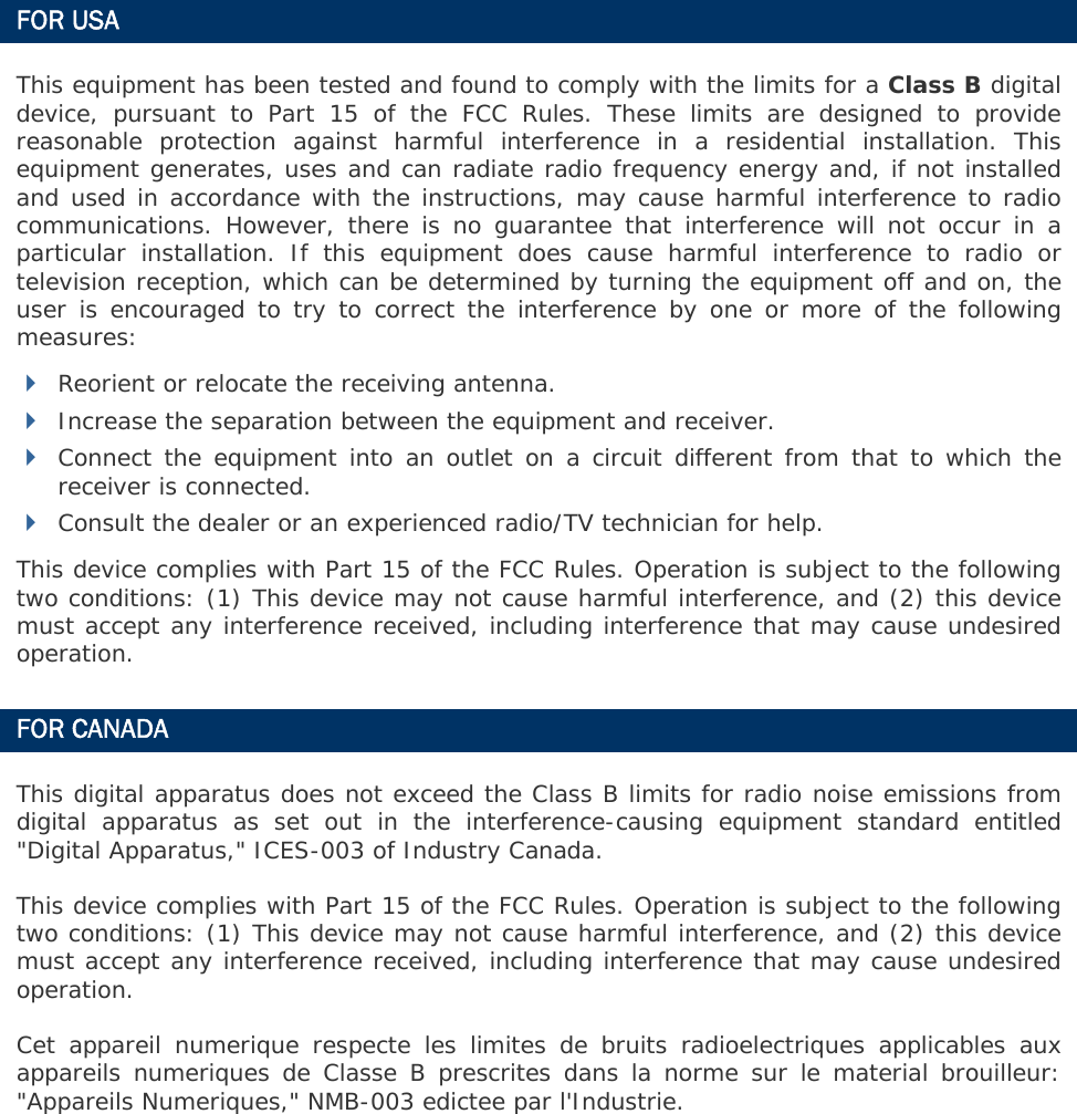
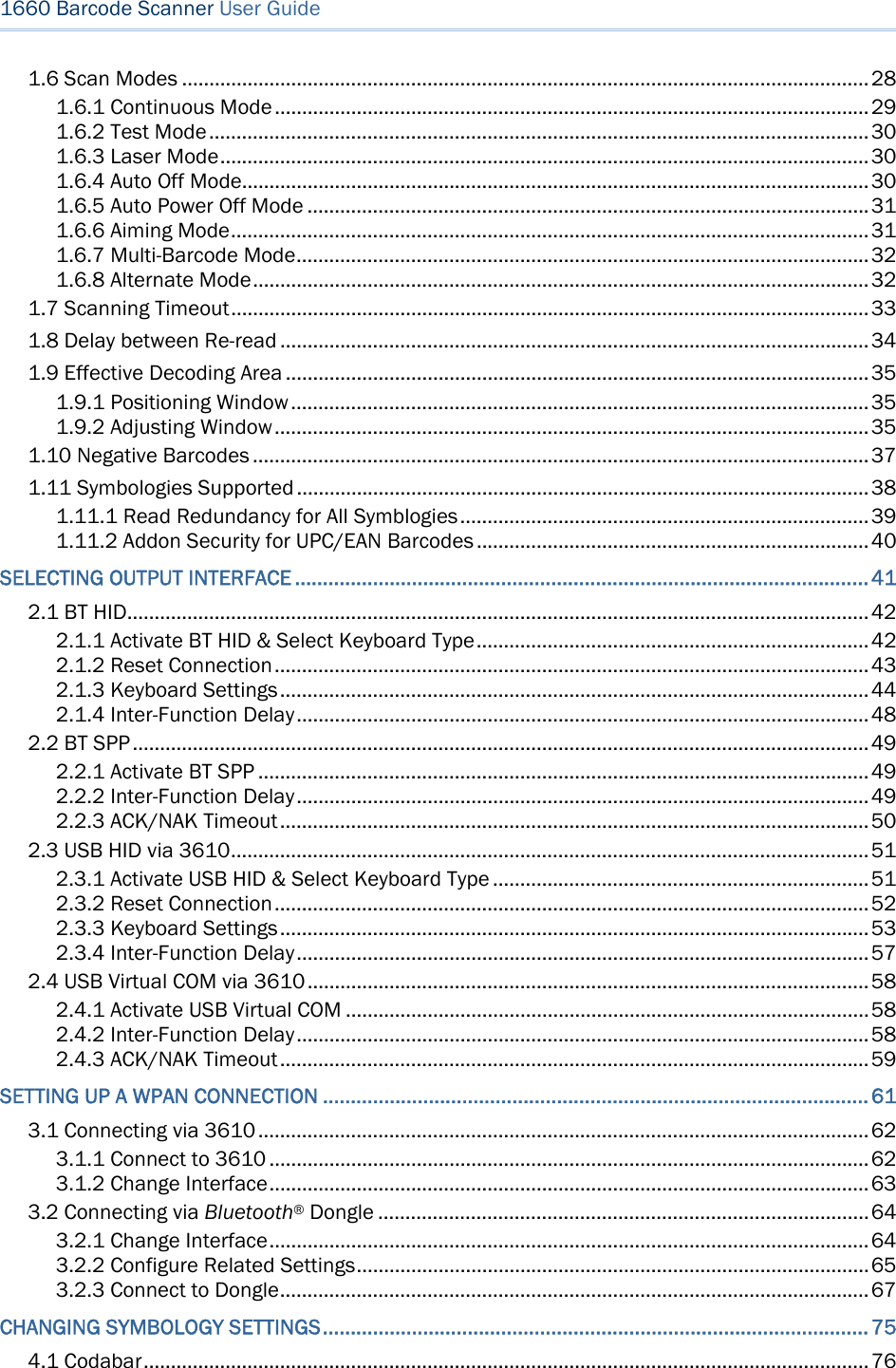
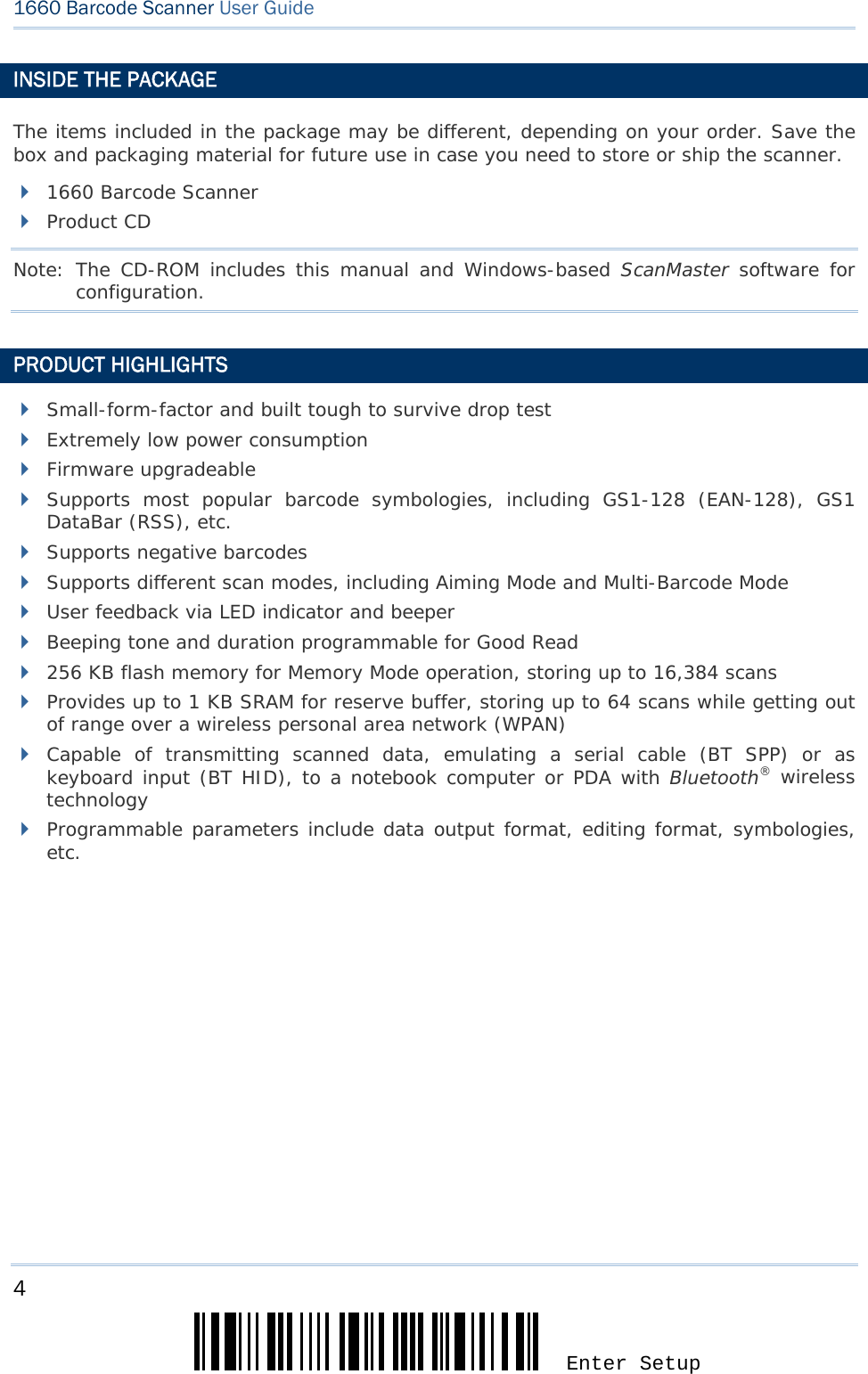
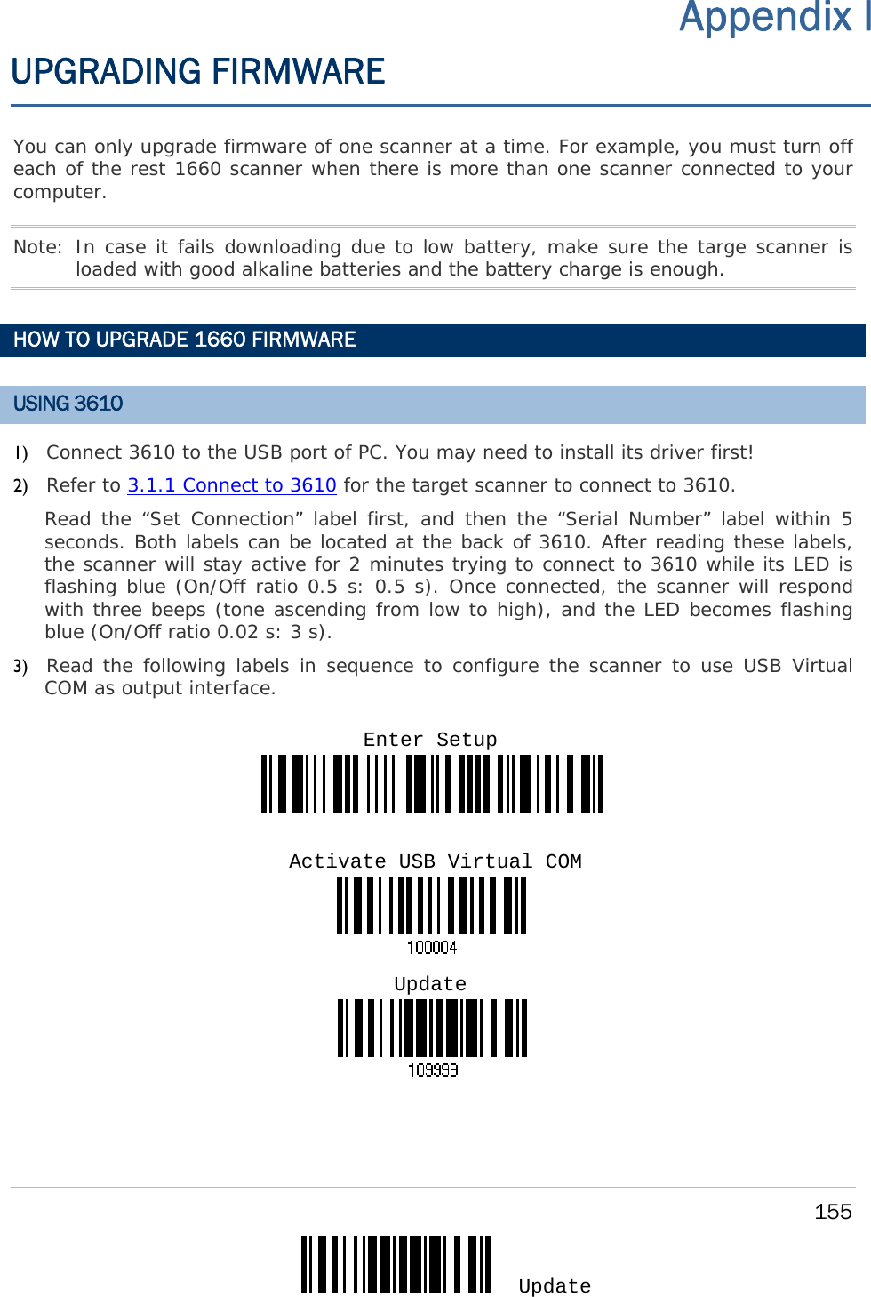
![3 Update 錯誤! 使用 [常用] 索引標籤將 Heading 1 套用到您想要在此處顯示的文字。 USING 3610 The BT Transponder is specifically designed for the scanner to communicate with a host computer wirelessly. The connection between the scanners and 3610 is made easy and reliable. Refer to 3.1.1 Connect to 3610. There is one LED indicator provided for communications status. Communication LED Meaning --- Blue, solid Initialize Red, solid --- Failed to establish a USB connection Red, solid Blue, solid Serial command mode with USB Virtual COM: wait 3 seconds for starting a serial command Red, flashing Blue, solid Serial command mode with USB HID: wait 3 seconds for pressing [NumLock] or [CapsLock] 5 times via keyboard --- Blue, flashing Wait for connection request from 1660 (Slow flash at 0.5 Hz) --- Blue, flashing Connected with 1660 (Fast flash at 1 Hz) Red, solid Blue, flashing Failed to send data to host via USB Virtual COM (Fast flash at 1 Hz) Red, flashing --- Enter Download Mode](https://usermanual.wiki/CipherLab/3610/User-Guide-1096354-Page-15.png)
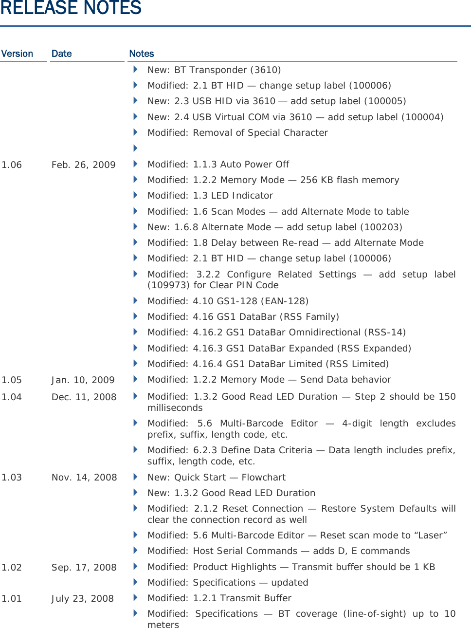
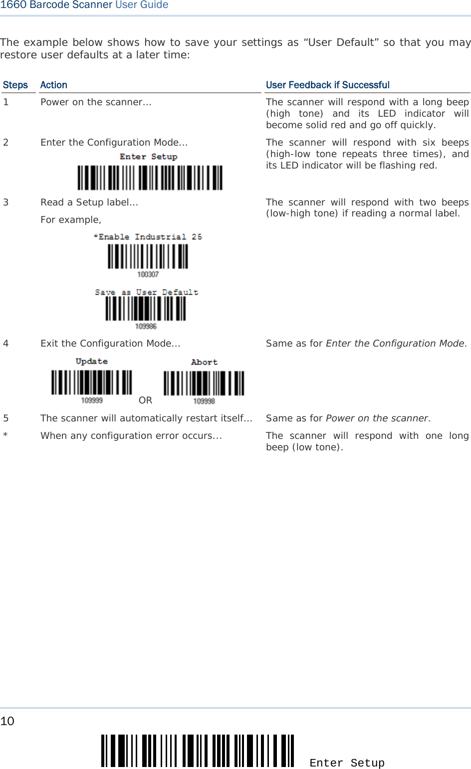
![5 Update The configuration of the scanner can be done by reading the setup labels contained in this manual or via the ScanMaster software. This section describes the procedure of configuring the scanner by reading the setup barcodes and provides some examples for demonstration. Configuration Mode 1. Press the [Power/Delete] key for 3 seconds to turn on the scanner. It will respond with a long beep and its LED will come on and off shortly. 2. Have the scanner read the “Enter Setup” label. It will respond with six beeps and its LED indicator will become flashing red after reading the label. 3. Have the scanner read more setup barcodes… Most of the setup barcodes are normal labels. The scanner will respond with two beeps (low-high tone). For special labels, it requires reading more than one setup barcode to complete the setting. 4. Have the scanner read the “Update” or “Abort” label. It will respond with six beeps and its LED indicator will become flashing red after reading the label. 5. The scanner will restart automatically upon reading the “Update” or “Abort” label. It will respond with a long beep and its LED will come on and off shortly. Note: Refer to Appendix II Host Serial Commands for how to configure the 3610 dongle by having the scanner read 3610-related setup labels or using serial commands. QUICK START](https://usermanual.wiki/CipherLab/3610/User-Guide-1096354-Page-17.png)
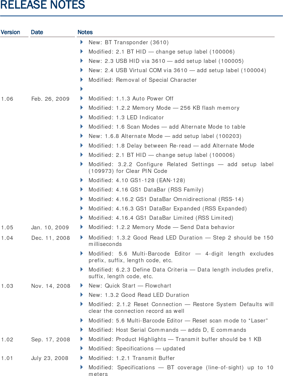
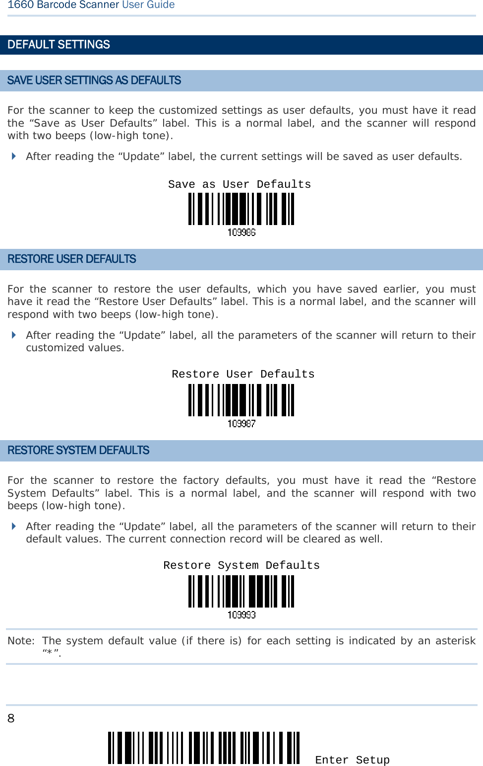
![7 Update 錯誤! 使用 [常用] 索引標籤將 Heading 1 套用到您想要在此處顯示的文字。 ENTER CONFIGURATION MODE For the scanner to enter the configuration mode, you must have it read the "Enter Setup" label, which can be located at the bottom of almost every even page of this manual. The scanner will respond with six beeps and its LED indicator will become flashing red after reading the label. For configuring scanner parameters, see “Read a Setup Label” below. EXIT CONFIGURATION MODE For the scanner to exit the configuration mode, you must have it read the “Update” label, which can be located at the bottom of almost every odd page of this manual. If you want to exit the configuration mode without saving any changes, have the scanner read the “Abort” label instead. Just like reading the “Enter Setup” label, the scanner will respond with six beeps and its LED indicator will become flashing red after reading the label. Wait for a few seconds for the scanner to restart itself. Enter SetupUpdate Abort](https://usermanual.wiki/CipherLab/3610/User-Guide-1096354-Page-19.png)
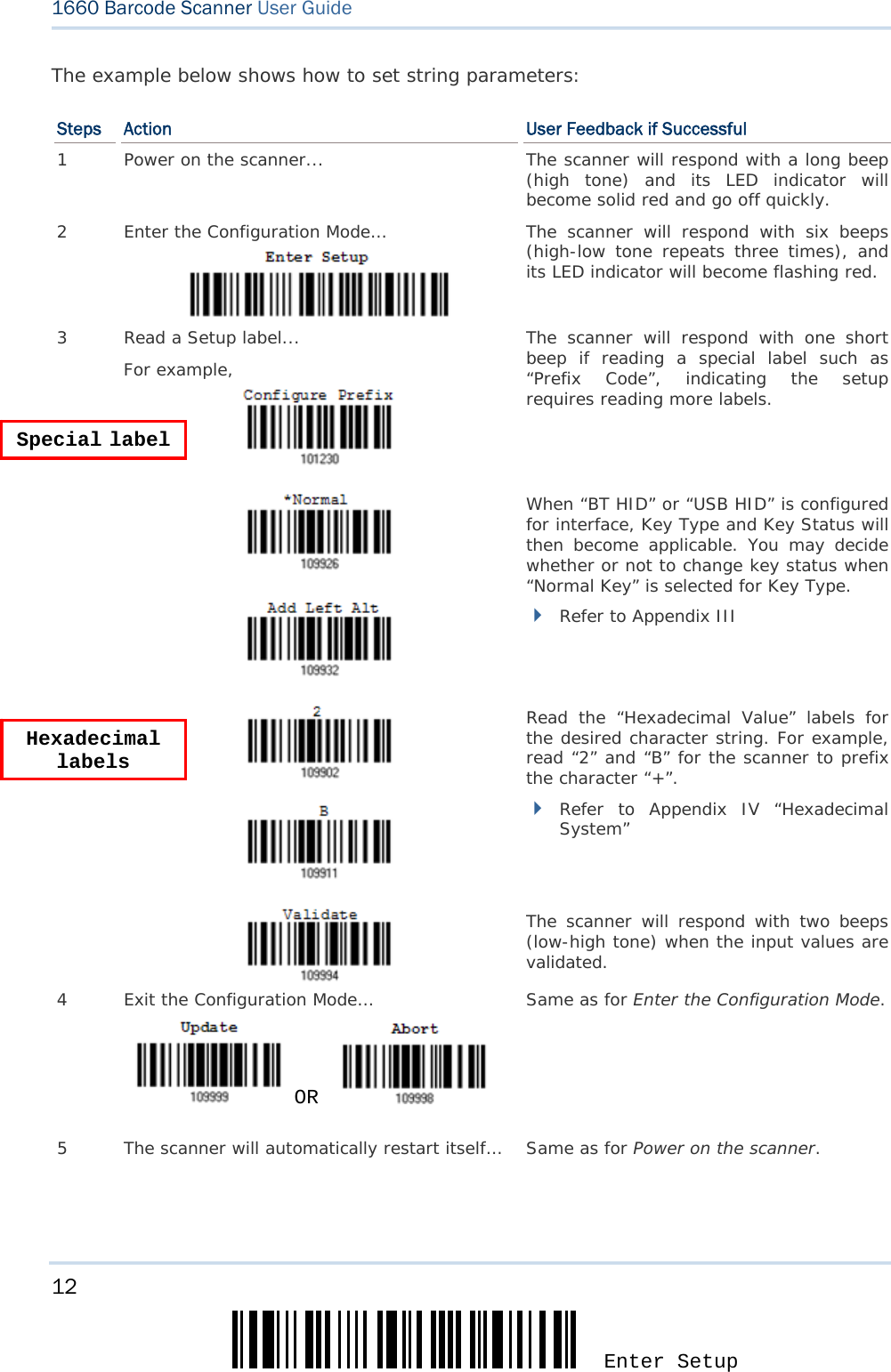
![9 Update 錯誤! 使用 [常用] 索引標籤將 Heading 1 套用到您想要在此處顯示的文字。 READ A SETUP LABEL CONFIGURE PARAMETERS For most of the scanner parameters, only one read is required to set them to new values. The scanner will respond with two beeps when each parameter is set successfully. But for a number of special parameters, multiple reads are required to complete the setting. In this case, the scanner will respond with a short beep to indicate it needs to read more setup labels. These special parameters may require reading one or more setup labels, such as Numeric labels, say, for keyboard type, inter-character delay, length qualification Hexadecimal labels, say, for character strings as prefix, suffix, etc. When “BT HID” or “USB HID” is configured for interface, Key Type and Key Status will then become applicable. You may decide whether or not to change key status when “Normal Key” is selected for Key Type. To complete the configuration of these special parameters, it requires reading the “Validate” label, and the scanner will respond with two beeps (low-high tone) to indicate the input values are validated.](https://usermanual.wiki/CipherLab/3610/User-Guide-1096354-Page-21.png)
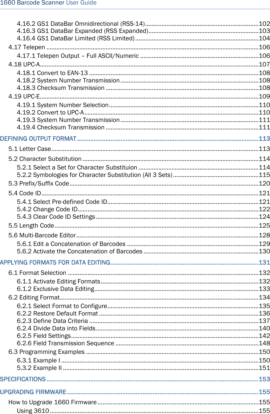
![11 Update 錯誤! 使用 [常用] 索引標籤將 Heading 1 套用到您想要在此處顯示的文字。 The example below shows how to set numeric parameters: Steps Action User Feedback if Successful 1 Power on the scanner... The scanner will respond with a long beep (high tone) and its LED indicator will become solid red and go off quickly. 2 Enter the Configuration Mode… The scanner will respond with six beeps (high-low tone repeats three times), and its LED indicator will become flashing red. 3 Read a Setup label... For example, The scanner will respond with two beeps (low-high tone) if reading a normal label. The scanner will respond with one short beep if reading a special label such as “Max. Length”, indicating the setup requires reading more labels. Read the “Decimal Value” label(s). Refer to Appendix IV “Decimal System” The scanner will respond with two beeps (low-high tone) when the input values are validated. 4 Exit the Configuration Mode… OR Same as for Enter the Configuration Mode. 5 The scanner will automatically restart itself… Same as for Power on the scanner. Normal label Normal label Special label Decimal label or labels](https://usermanual.wiki/CipherLab/3610/User-Guide-1096354-Page-23.png)
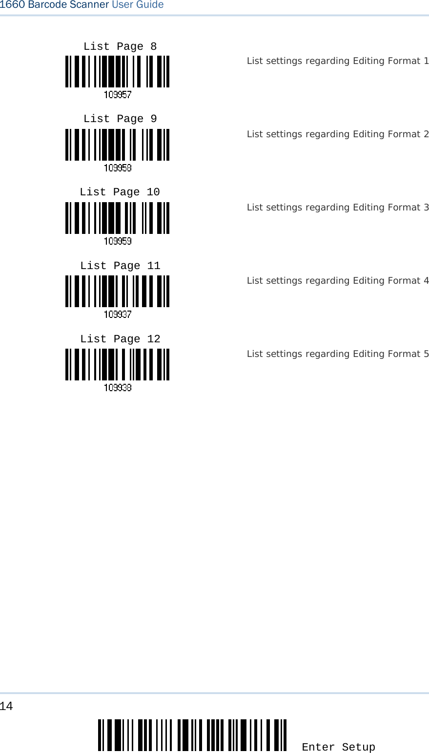
![13 Update 錯誤! 使用 [常用] 索引標籤將 Heading 1 套用到您想要在此處顯示的文字。 LIST THE CURRENT SETTINGS The current settings of all scanner parameters can be sent to the host computer for user inspection. The listing includes ten pages as shown below. You can select the page of interest by having the scanner read the “List Page x” label. The scanner will respond with two beeps (low-high tone) and send the selected page to the host immediately. List settings regarding Interface, Buzzer, and Other Scanner Parameters List settings regarding Prefix, Postfix, and Length Code Setting List settings regarding Code ID List settings regarding: Readable Symbologies List settings regarding Symbology Parameters (1/3) List settings regarding Symbology Parameters (2/3) List settings regarding Symbology Parameters (3/3) List Page 1 List Page 2 List Page 3 List Page 4 List Page 5 List Page 6 List Page 7](https://usermanual.wiki/CipherLab/3610/User-Guide-1096354-Page-25.png)
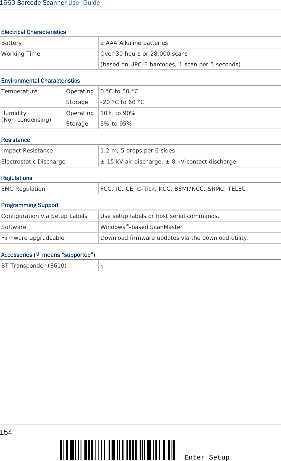
![15 Update This chapter explains the features and usage of the barcode scanner. IN THIS CHAPTER 1.1 Battery ..................................................................... 15 1.2 Memory .................................................................... 18 1.3 LED Indicator ............................................................ 21 1.4 Beeper ..................................................................... 23 1.5 Send "NR" to Host ..................................................... 27 1.6 Scan Modes .............................................................. 28 1.7 Scanner Time-out ...................................................... 33 1.8 Delay between Re-read............................................... 34 1.9 Effective Decoding Area .............................................. 35 1.10 Negative Barcodes ................................................... 37 1.11 Symbologies Supported ............................................ 38 1.1 BATTERY The scanner is powered by two AAA Alkaline batteries. During normal operation, the scanner can work for over 30 hours or 28,000 scans (based on UPC-E barcodes, 1 scan per 5 seconds). For intensive data collection, you may prepare spare batteries for non-stop operation. Note: The 1660 scanner can be configured to save battery power. Refer to settings of “Auto Power Off”, “Sniff Mode”, as well as “Low Battery Alarm”. 1.1.1 HOW TO OPERATE THE SCANNER Turn on the scanner… Press the [Power/Delete] key for 3 seconds. The scanner will respond with a long beep (high tone) and its LED indicator will become solid red and go off quickly. Turn off the scanner… Press the [Power/Delete] key for 2 seconds. The scanner will respond with two short beeps (high tone) and the LED will finally become solid red. Release the key then. Otherwise, let the scanner turn off automatically in specific circumstances. Delete the last collected data when in memory mode … Press the [Power/Delete] key. The scanner will respond with two short beeps (high tone) and the LED will become solid red. Before the LED goes off (within 1 second), press the [Power/Delete] key again to confirm the deletion. Chapter 1 UNDERSTANDING THE BARCODE SCANNER](https://usermanual.wiki/CipherLab/3610/User-Guide-1096354-Page-27.png)
![16 Enter Setup 1660 Barcode Scanner User Guide 1.1.2 AUTO POWER OFF Specify the time interval (1~254 min.; 0= Disable) for the scanner to automatically turn off in the following circumstances. By default, it is set to 10 minutes. If this feature is not desired, set it to 0. Auto Power Off before establishing a WPAN connection successfully... 1. The 1660 scanner will stay active for 2 minutes waiting for a connection request from the host (SPP) or trying to connect to the host (HID). Its CPU is running at full speed, and the LED is flashing blue (On/Off ratio 0.5 s: 0.5 s). 2. If it fails to connect within 2 minutes, the scanner will become inactive to save power for the remaining period of time (the specified value minus 2 minutes). Its CPU is running at low speed, and the LED is flashing red (On/Off ratio 0.5 s: 2 s). Press the [Trigger] key to wake up the scanner when it becomes inactive, and the scanner will stay active for 2 minutes again. 3. If it fails to connect again and again, and finally stays inactive until the specified time interval has elapsed, the scanner will automatically turn off in order to conserve battery power. Hold down the [Power/Delete] key for 3 seconds to turn it on. On your computer, you will have to search for the scanner again. Auto Power Off after establishing a WPAN connection successfully... Once a WPAN connection is established successfully, the LED is flashing blue (On/Off ratio 0.02 s: 3 s). If the scanner is idle during the specified time interval for Auto Power Off, it will automatically turn off when the time is up. You will hear three short beeps, tone descending from high to low. For BT HID or SPP, there is no transition from full CPU speed to low CPU speed. However, when connecting with 3610, the scanner will go through the transition in order to save power. For BT HID, the scanner will resume connection with the host upon powering on again, as long as the host application is running. You will hear three short beeps, tone ascending from low to high. If the scanner fails to resume connection, it will try every five second to re-connect to the host unless you have the scanner read the Reset Connection label. For BT SPP, the scanner must wait for the host to re-connect. With the use of 3610, the scanner will try every five second to re-connect to 3610 unless you have the scanner read the Reset Connection label.](https://usermanual.wiki/CipherLab/3610/User-Guide-1096354-Page-28.png)
![17 Update Chapter 1 錯誤! 使用 [常用] 索引標籤將 Heading 1 套用到您想要在此處顯示的文字。 1) Read the label above to specify the time interval before the scanner automatically turns off. 2) Read the “Decimal Value” label on page 169. For example, read “1” and “5” for the scanner to automatically turn off after being idle for 15 minutes. 3) Read the “Validate” label on the same page to complete this setting. Auto Off after 0~254 minutes (*10)](https://usermanual.wiki/CipherLab/3610/User-Guide-1096354-Page-29.png)
![19 Update Chapter 1 錯誤! 使用 [常用] 索引標籤將 Heading 1 套用到您想要在此處顯示的文字。 Memory Data Delay You may set a delay between each data record while transmitting data back to the server. *None 1 sec 2 sec 3 sec 5 sec 8 sec 500 ms 250 ms](https://usermanual.wiki/CipherLab/3610/User-Guide-1096354-Page-31.png)
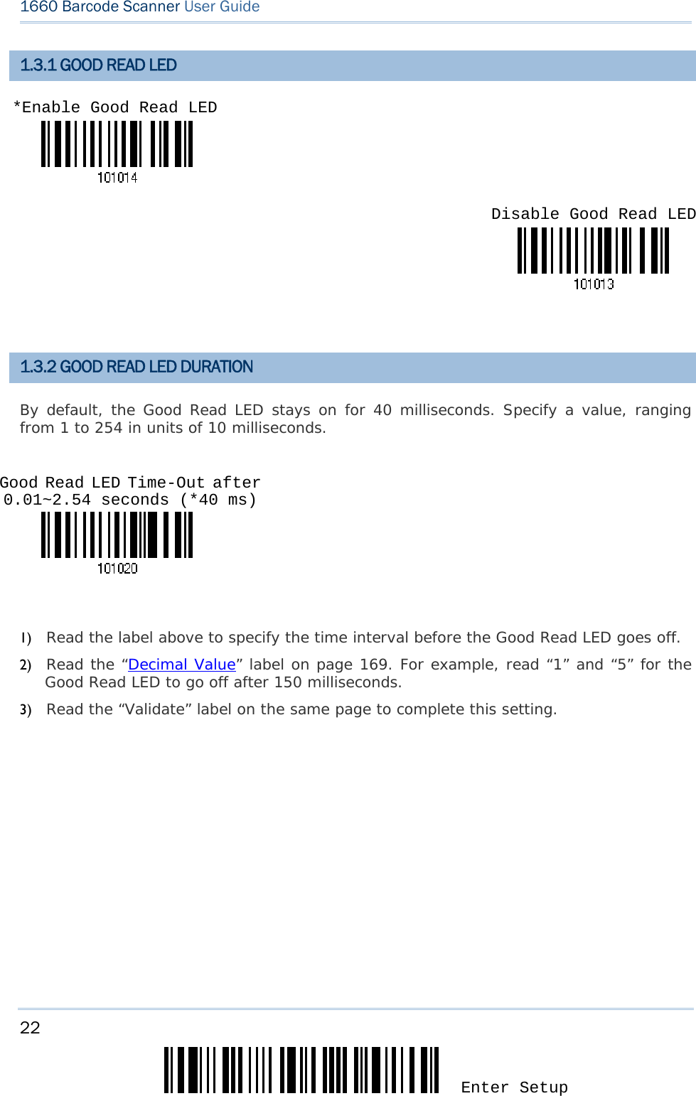
![21 Update Chapter 1 錯誤! 使用 [常用] 索引標籤將 Heading 1 套用到您想要在此處顯示的文字。 1.3 LED INDICATOR The triple-color LED on top of the scanner is used to provide user feedback. For example, the LED becomes solid red and goes off quickly upon powering on or running out of transmit buffer. You may tell the difference by the beeps – you will hear a long beep of high tone when powering on the scanner, and a long beep of low tone when the transmit buffer becomes full. Scanner LED Meaning Red, flashing Charging (On/Off ratio 0.5 s: 0.5 s) Red, solid Charging error Red, on-off Power on, with one long beep (high tone, LED on for 1 s) Transmit buffer full, with one long beep (low tone) Memory full, with two short beeps (high-low tone) Green, on-off Good Read, with one short beep (high tone) and beeper pitch and duration programmable Blue, flashing First, flashing blue (On/Off ratio 0.5 s: 0.5 s) for two minutes indicates the scanner is waiting for connection, and goes off if no connection is established, then flashing red (On/Off ratio 0.5 s: 2 s) indicates the scanner is inactive. It is ready for connection only while the LED is flashing blue — SPP: waiting host to connect HID: trying to connect to host Using 3610: trying to connect to 3610 Red, flashing Flashing red (On/Off ratio 0.5 s: 2 s) indicates the scanner is inactive and its CPU running at low speed to save power — No WPAN connection is established after waiting for two minutes Blue, flashing Flashing blue (On/Off ratio 0.1 s: 0.1 s) indicates the scanner receives a PIN code request from host (flashing more quickly than waiting connection). Blue, flashing Flashing blue (On/Off ratio 0.02 s: 3 s) indicates the scanner has established a WPAN connection successfully. Red, flashing Blue, flashing Flashing red and blue indicates an error occurs while entering the PIN code. Press the [Trigger] key to get ready for re-connecting. Red, flashing Configuration Mode (On/Off ratio 1 s: 1 s)](https://usermanual.wiki/CipherLab/3610/User-Guide-1096354-Page-33.png)
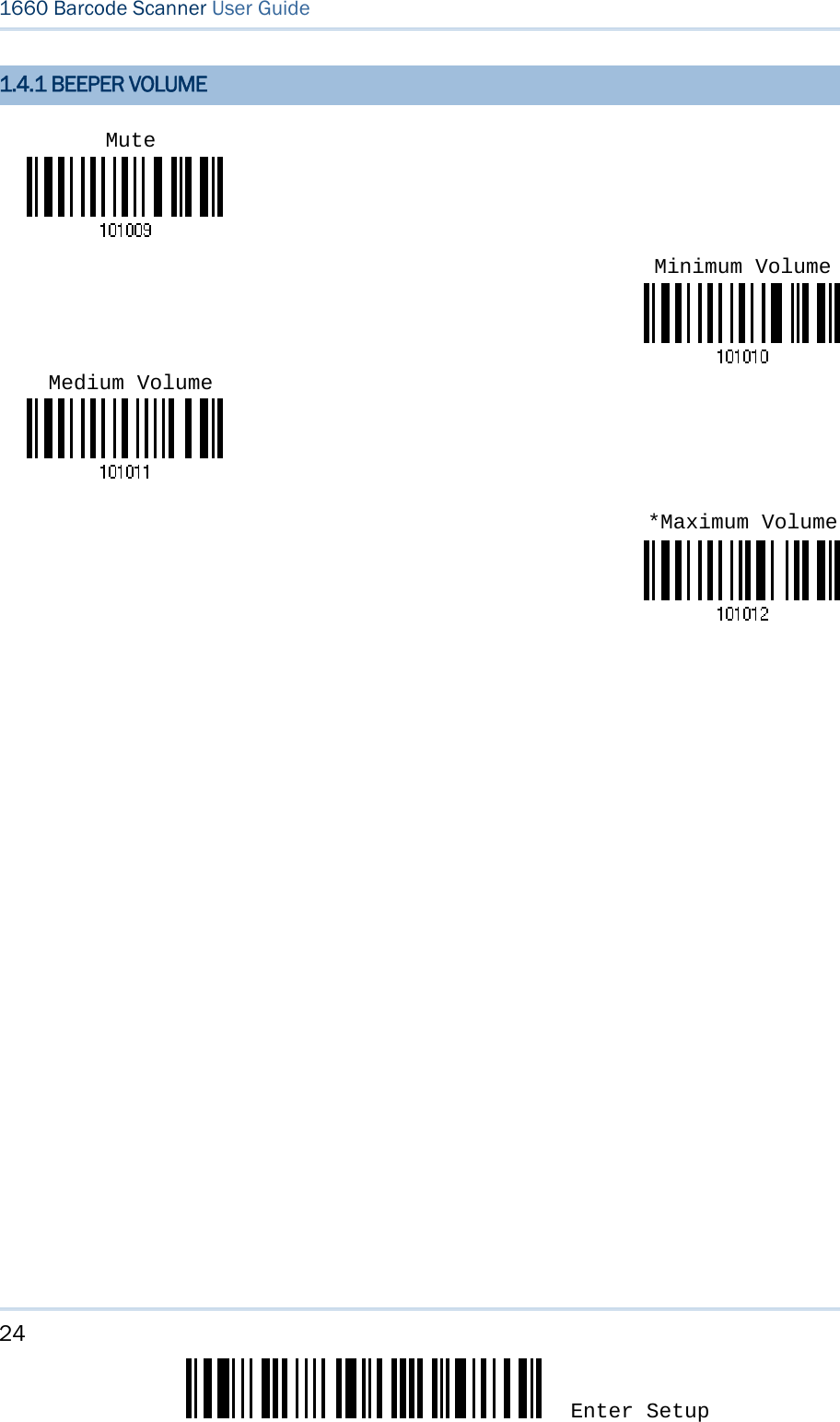
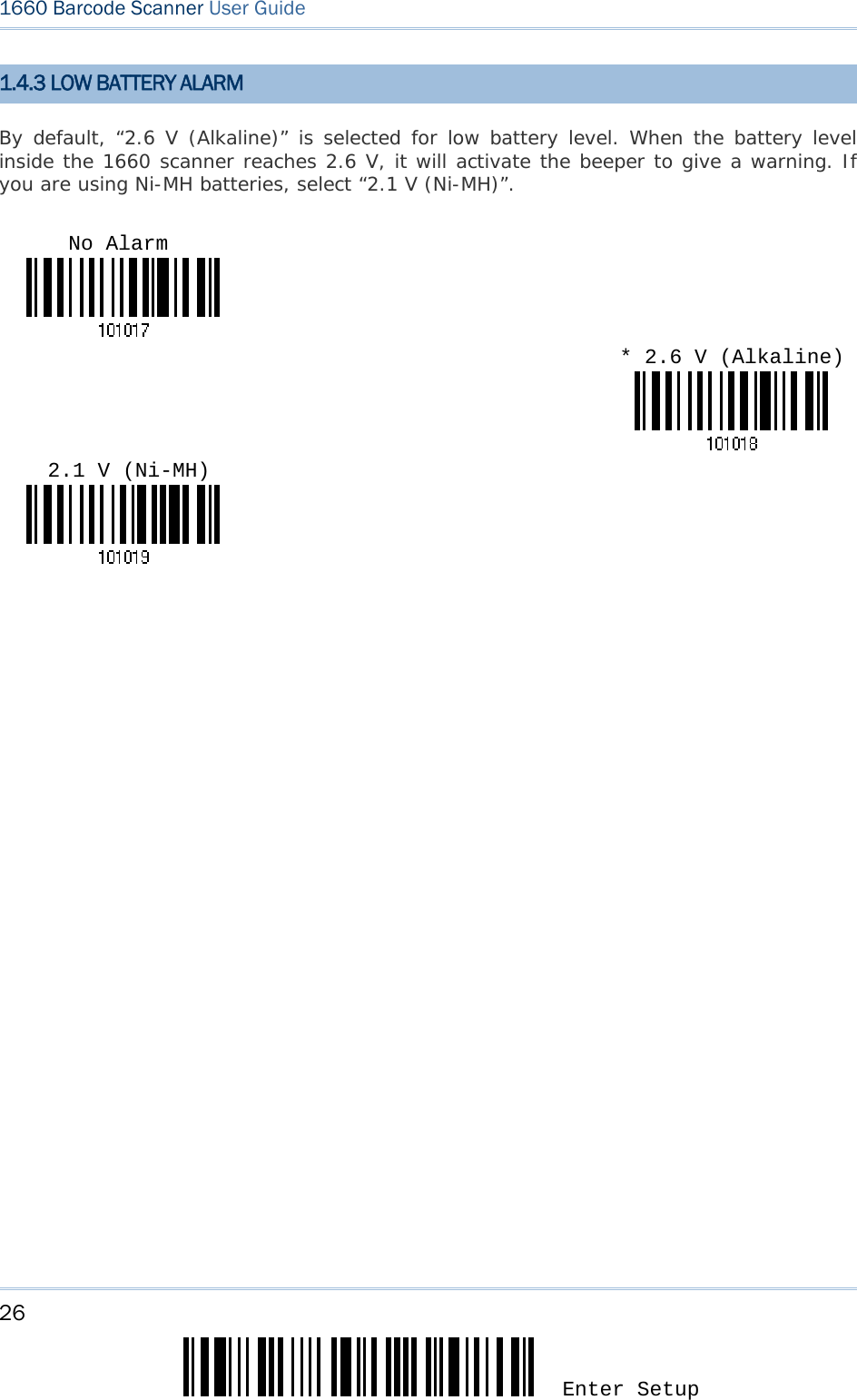
![23 Update Chapter 1 錯誤! 使用 [常用] 索引標籤將 Heading 1 套用到您想要在此處顯示的文字。 1.4 BEEPER The scanner has a buzzer to provide user feedback in various operating conditions. Beeping Meaning One long beep, high tone Power on, with red LED on (1 s) and off quickly two short beeps, high tone Power off, with green LED on and off quickly, and finally red LED on One short beep, high tone (programmable, default to 4 KHz) Good Read, with green LED on and off quickly Six short beeps, high-low tone repeats three times Enter Configuration Mode, with red LED flashing Exit Configuration Mode Two short beeps, low-high tone Setup label read successfully One short beep, high tone More setup label required One long beep, low tone Transmit Buffer Full, with red LED on and off quickly Configuration Error (Wrong label…) Two short beeps, high-low tone Data saved to Transmit Buffer (out of range) Memory Mode – Memory Full, with red LED on and off quickly Two long beeps, high-low tone Multi-Barcode Mode – Buffer Full Three short beeps, tone ascending from low to high WPAN connection established, with blue LED flashing WPAN connection resumed, with blue LED flashing Three short beeps, tone ascending from high to low WPAN connection out of range or suspended](https://usermanual.wiki/CipherLab/3610/User-Guide-1096354-Page-35.png)
![25 Update Chapter 1 錯誤! 使用 [常用] 索引標籤將 Heading 1 套用到您想要在此處顯示的文字。 1.4.2 GOOD READ BEEP Frequency Duration 8 kHz * 4 kHz 2 kHz 1 kHz *Shortest Longer Longest Shorter](https://usermanual.wiki/CipherLab/3610/User-Guide-1096354-Page-37.png)
![27 Update Chapter 1 錯誤! 使用 [常用] 索引標籤將 Heading 1 套用到您想要在此處顯示的文字。 1.5 SEND “NR” TO HOST The scanner can send the “NR” string to the host to notify the No Read event. Enable *Disable](https://usermanual.wiki/CipherLab/3610/User-Guide-1096354-Page-39.png)
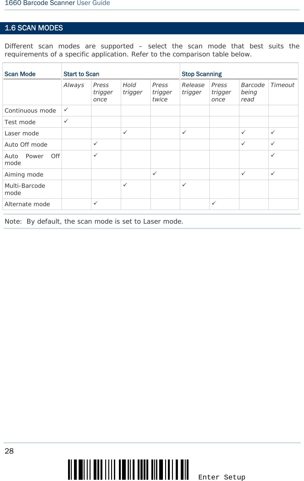
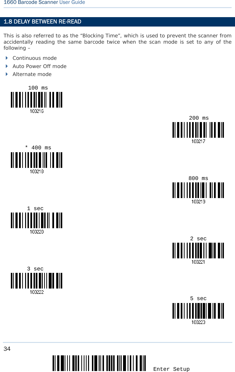
![29 Update Chapter 1 錯誤! 使用 [常用] 索引標籤將 Heading 1 套用到您想要在此處顯示的文字。 1.6.1 CONTINUOUS MODE The scanner is always scanning. After a successful decoding, the removal of barcode is required. It is not allowed to proceed to decode until the decoding delay time has passed. To decode the same barcode repeatedly, move away the barcode and put it back again and again for scanning. Note: Refer to “Delay between Re-read”. Decoding Delay Set the time interval between each decoding. Continuous Mode *Disable 0.5 sec 1 sec 2 sec](https://usermanual.wiki/CipherLab/3610/User-Guide-1096354-Page-41.png)
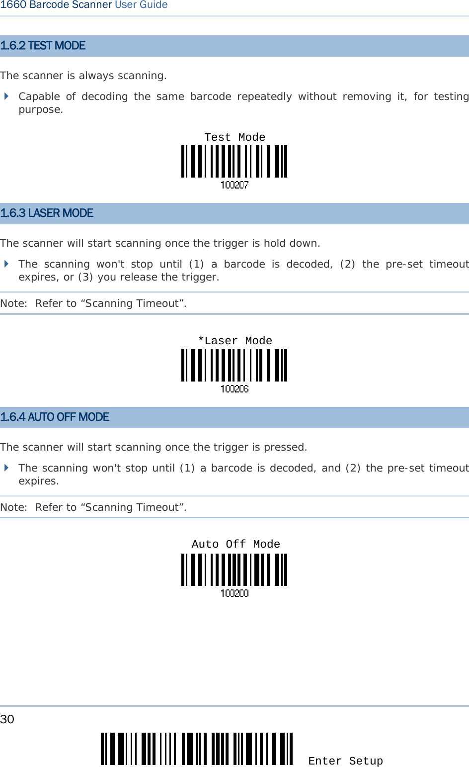
![31 Update Chapter 1 錯誤! 使用 [常用] 索引標籤將 Heading 1 套用到您想要在此處顯示的文字。 1.6.5 AUTO POWER OFF MODE The scanner will start scanning once the trigger is pressed. The scanning won't stop until the pre-set timeout expires, and, the pre-set timeout period re-counts after each successful decoding. Note: Refer to “Delay between Re-read” and “Scanning Timeout”. 1.6.6 AIMING MODE The scanner will aim at a barcode once the trigger is pressed, and start scanning when the trigger is pressed again within one second. The scanning won't stop until (1) a barcode is decoded, and (2) the pre-set timeout expires. Aiming Timeout You can limit the aiming time interval (1~15). By default, the scanner time-out is set to 1 second. 1. Read the label above to specify the time interval before aiming ends. (It is set to 1 by default.) 2. Read the “Decimal Value” label on page 169. For example, read “1” and “0” for the scanner to automatically shut down after being idle for 10 seconds. 3. Read the “Validate” label on the same page to complete this setting. Auto Power Off ModeAiming Mode Aiming Time-Out after 1~15 seconds (*1)](https://usermanual.wiki/CipherLab/3610/User-Guide-1096354-Page-43.png)
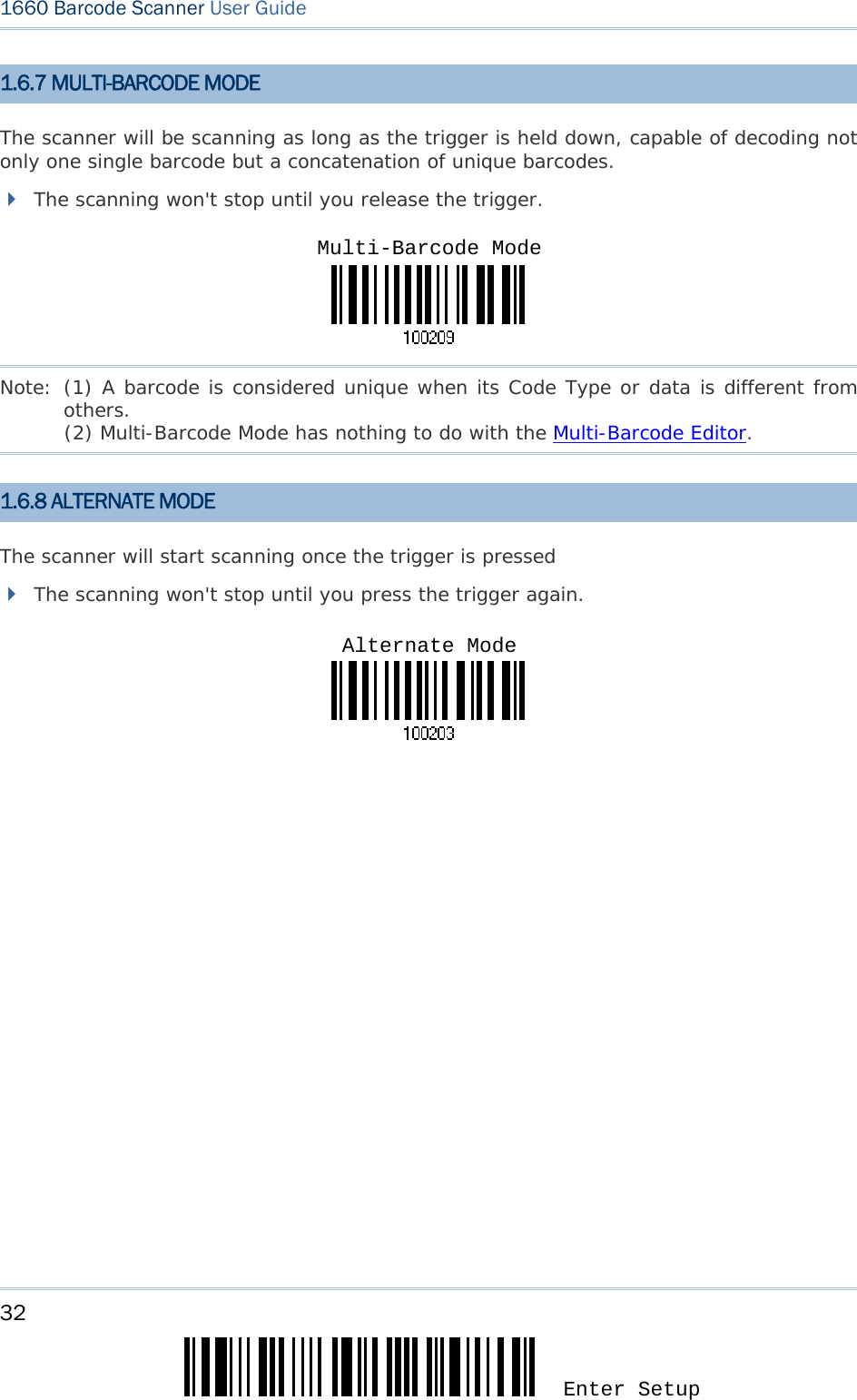
![33 Update Chapter 1 錯誤! 使用 [常用] 索引標籤將 Heading 1 套用到您想要在此處顯示的文字。 1.7 SCANNING TIMEOUT Specify the scanning time interval (1~254 sec.; 0= Disable) when the scan mode is set to any of the following – Laser mode Auto Off mode Auto Power Off mode Aiming mode 1) Read the label above to specify the time interval before the scan engine times out. 2) Read the “Decimal Value” label on page 169. For example, read “1” and “5” for the scanner to automatically shut down after being idle for 15 seconds. 3) Read the “Validate” label on the same page to complete this setting. Scanner Time-Out after 0~254 seconds (*10)](https://usermanual.wiki/CipherLab/3610/User-Guide-1096354-Page-45.png)
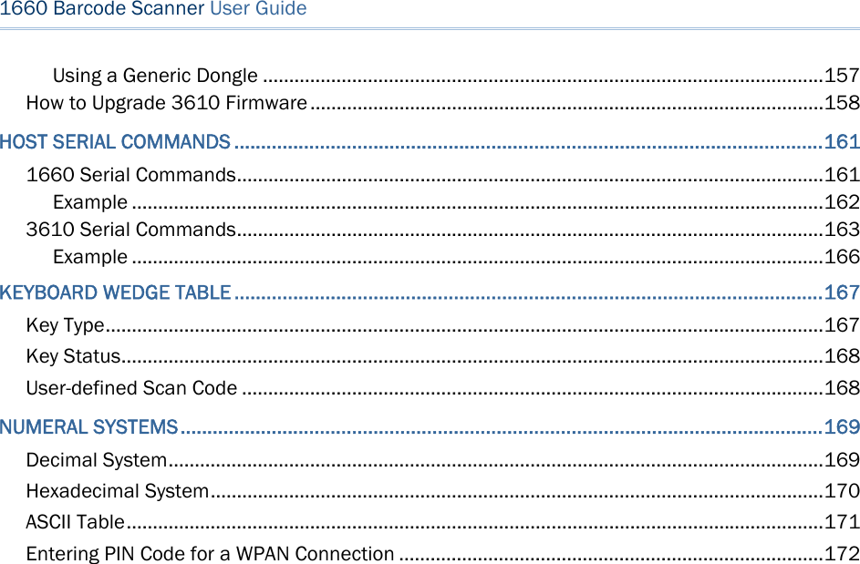
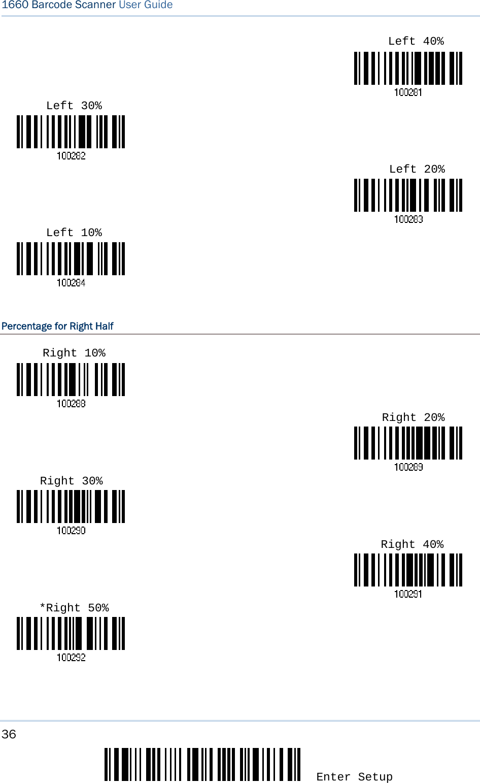
![35 Update Chapter 1 錯誤! 使用 [常用] 索引標籤將 Heading 1 套用到您想要在此處顯示的文字。 1.9 EFFECTIVE DECODING AREA By default, the effective decoding area is 100% covered by the scanned area. However, you may narrow down the decoding area to prevent reading the wrong barcode when a number of barcodes are printed closely. The scanner will only read barcodes that appear in the effective decoding area. Read the label “Centering On” and specify the percentage to narrow down the decoding area. For example, read “Left 10%” and then “Right 30%” for the scanner to decode barcode “A” only. 1.9.1 POSITIONING WINDOW 1.9.2 ADJUSTING WINDOW Percentage for Left Half Centering On *Centering Off *Left 50%](https://usermanual.wiki/CipherLab/3610/User-Guide-1096354-Page-47.png)
![37 Update Chapter 1 錯誤! 使用 [常用] 索引標籤將 Heading 1 套用到您想要在此處顯示的文字。 1.10 NEGATIVE BARCODES Normally, barcodes are printed with the color of the bars darker than that of the spaces. But for negative barcodes, they are printed in the opposite sense just like negative films. The spaces of negative barcodes are printed with a color darker than that of the bars. You can configure the scanner to be able to read negative barcodes. Enable *Disable](https://usermanual.wiki/CipherLab/3610/User-Guide-1096354-Page-49.png)
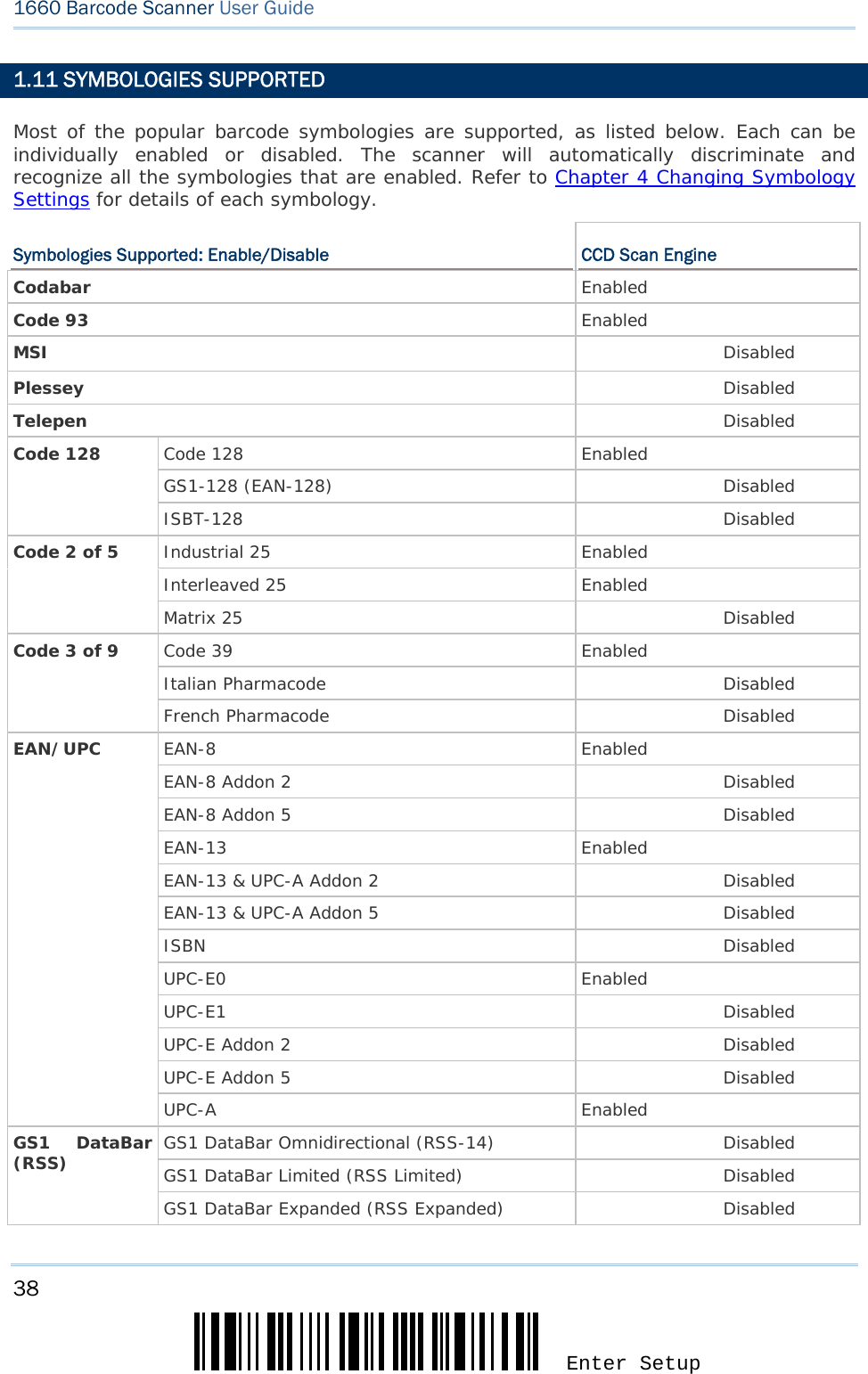
![39 Update Chapter 1 錯誤! 使用 [常用] 索引標籤將 Heading 1 套用到您想要在此處顯示的文字。 1.11.1 READ REDUNDANCY FOR ALL SYMBLOGIES Select the level of reading security. For example, If "No Redundancy" is selected, one successful decoding will make the reading valid and induce the "READER Event". If "Three Times" is selected, it will take a total of four consecutive successful decodings of the same barcode to make the reading valid. The higher the reading security is (that is, the more redundancy the user selects), the slower the reading speed gets. It is obvious that the more redundancy you select, the higher the reading security is, and thus, the slower the reading speed becomes. You will have to compromise between reading security and decoding speed. *No Redundancy Two Times One Time Three Times](https://usermanual.wiki/CipherLab/3610/User-Guide-1096354-Page-51.png)
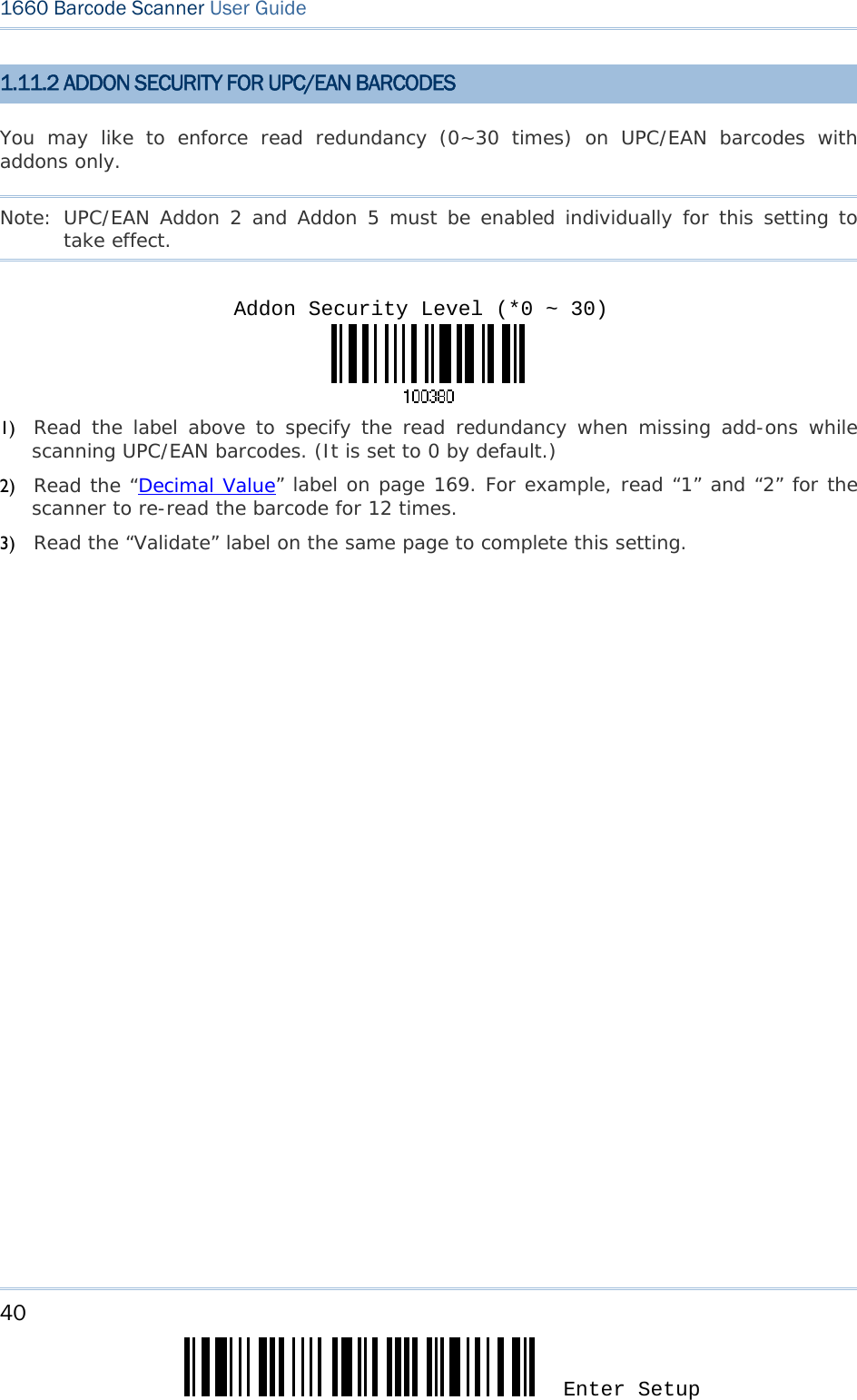
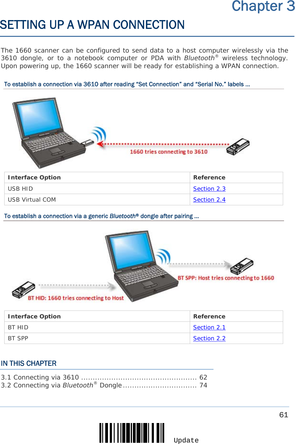
![41 Update In order to establish a proper connection between your computer and the scanner, we suggest that you follow these instructions – 1) Install batteries and press the [Power/Delete] key for 3 seconds to turn on the scanner. 2) Have the scanner read the “Enter Setup” label to enter the configuration mode. 3) Have the scanner read the associated label to activate the desired interface. See the following sections for output interfaces supported. 4) Have the scanner read the labels for related settings. 5) Have the scanner read the “Update” label to exit the configuration mode. 6) Turn on your computer or laptop and establish a WPAN connection with the scanner. Refer to Chapter 3 – Setting up a WPAN Connection. Note: By default, the output interface is set to “BT HID”. IN THIS CHAPTER 2.1 BT HID ..................................................................... 42 2.2 BT SPP ..................................................................... 49 2.3 USB HID via 3610 ...................................................... 51 2.4 USB Virtual COM via 3610 ........................................... 58 Chapter 2 SELECTING OUTPUT INTERFACE](https://usermanual.wiki/CipherLab/3610/User-Guide-1096354-Page-53.png)
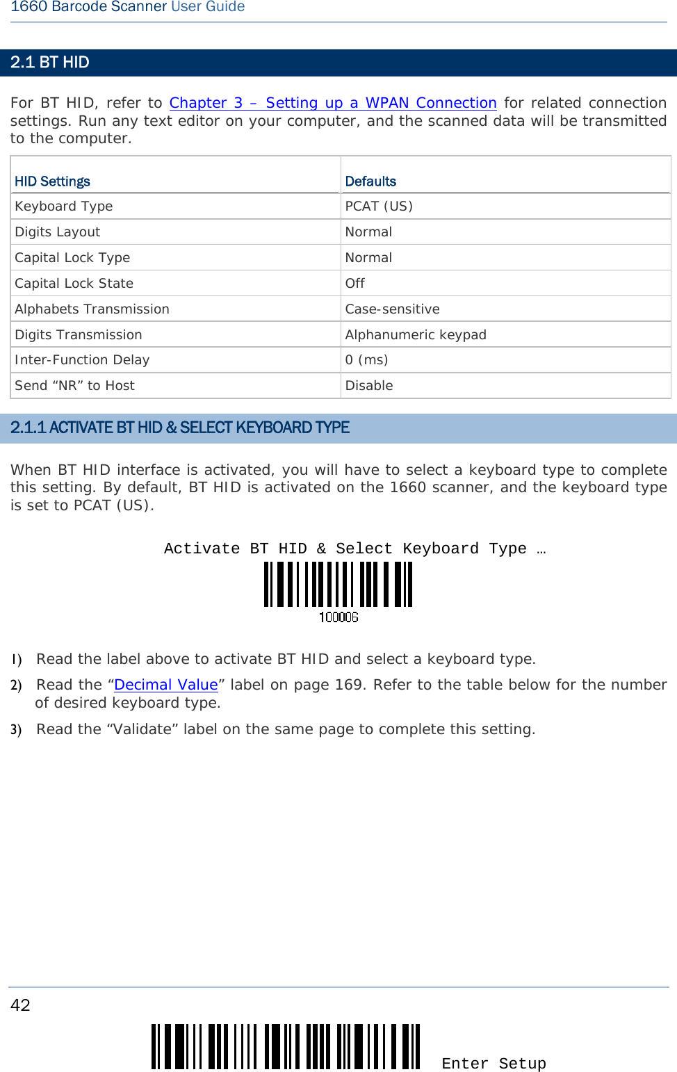
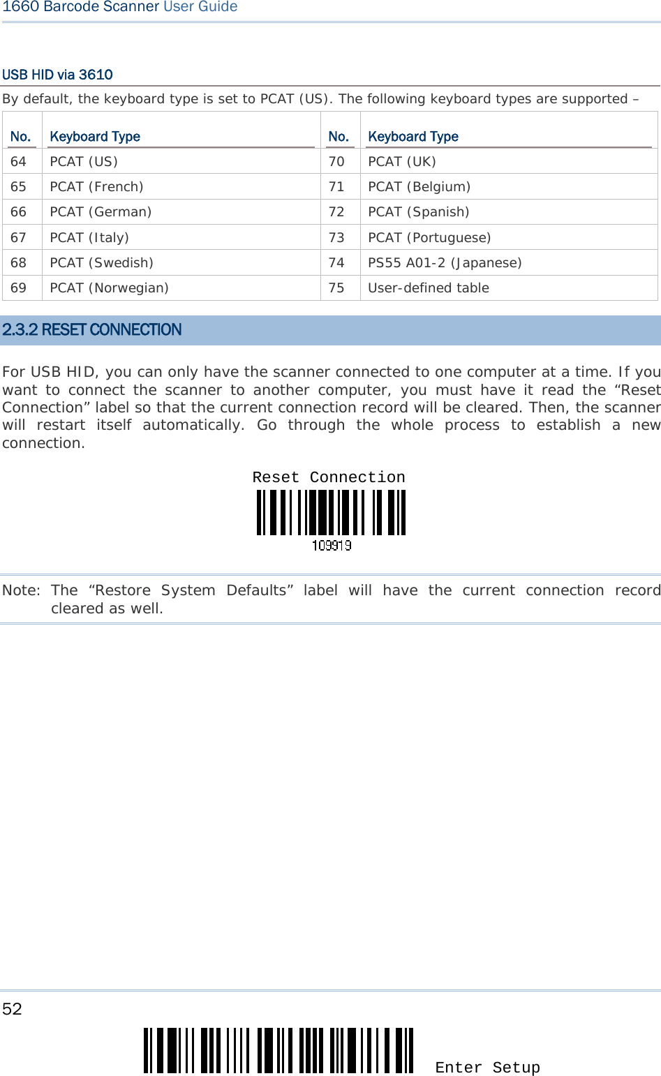
![43 Update Chapter 2 錯誤! 使用 [常用] 索引標籤將 Heading 1 套用到您想要在此處顯示的文字。 BT HID By default, the keyboard type is set to PCAT (US). The following keyboard types are supported – No. Keyboard Type No. Keyboard Type 64 PCAT (US) 70 PCAT (UK) 65 PCAT (French) 71 PCAT (Belgium) 66 PCAT (German) 72 PCAT (Spanish) 67 PCAT (Italy) 73 PCAT (Portuguese) 68 PCAT (Swedish) 74 PS55 A01-2 (Japanese) 69 PCAT (Norwegian) 75 User-defined table 2.1.2 RESET CONNECTION For BT HID, you can only have the scanner connected to one computer at a time. If you want to connect the scanner to another computer, you must have it read the “Reset Connection” label so that the current connection record will be cleared. Then, the scanner will restart itself automatically. Go through the whole process to establish a new connection. Note: The “Restore System Defaults” label will have the current connection record cleared as well. Reset Connection](https://usermanual.wiki/CipherLab/3610/User-Guide-1096354-Page-55.png)
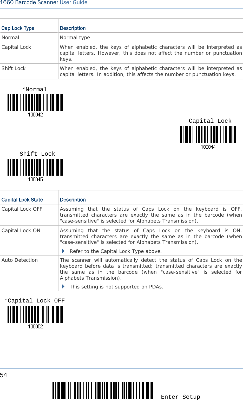
![44 Enter Setup 1660 Barcode Scanner User Guide 2.1.3 KEYBOARD SETTINGS Digits Layout Capital Lock Type Capital Lock Setting Alphabets Transmission Digits Transmission Note: BT HID does not support these functions on PDAs – (1) Capital Lock Setting: Auto Detection (2) Digits Transmission: Numeric Key Digits Layout Select a proper layout that matches the alphabets layout. The scanner will make adjustments according to this setting. Options Description Normal Depends on the [Shift] key or [Shift Lock] setting Lower Row For QWERTY or QWERTZ keyboard Upper Row For AZERTY keyboard Note: This setting is to be used with the Character Substitution setting when support to certain keyboard types (languages) is unavailable but required. Capital Lock Type & Setting In order to send the alphabets with correct case, the scanner needs to know the status of Caps Lock on the keyboard. Incorrect settings may result in reversed case of the alphabets being transmitted. *Normal Lower Row Upper Row](https://usermanual.wiki/CipherLab/3610/User-Guide-1096354-Page-56.png)
![45 Update Chapter 2 錯誤! 使用 [常用] 索引標籤將 Heading 1 套用到您想要在此處顯示的文字。 Cap Lock Type Description Normal Normal type Capital Lock When enabled, the keys of alphabetic characters will be interpreted as capital letters. However, this does not affect the number or punctuation keys. Shift Lock When enabled, the keys of alphabetic characters will be interpreted as capital letters. In addition, this affects the number or punctuation keys. Capital Lock State Description Capital Lock OFF Assuming that the status of Caps Lock on the keyboard is OFF, transmitted characters are exactly the same as in the barcode (when "case-sensitive" is selected for Alphabets Transmission). Capital Lock ON Assuming that the status of Caps Lock on the keyboard is ON, transmitted characters are exactly the same as in the barcode (when "case-sensitive" is selected for Alphabets Transmission). Refer to the Capital Lock Type above. Auto Detection The scanner will automatically detect the status of Caps Lock on the keyboard before data is transmitted; transmitted characters are exactly the same as in the barcode (when "case-sensitive" is selected for Alphabets Transmission). This setting is not supported on PDAs. *Capital Lock OFF Capital Lock Shift Lock *Normal](https://usermanual.wiki/CipherLab/3610/User-Guide-1096354-Page-57.png)
![46 Enter Setup 1660 Barcode Scanner User Guide Alphabets Transmission By default, the alphabets transmission is case-sensitive, meaning that the alphabets will be transmitted according to their original case, the status of Caps Lock on the keyboard, as well as the Capital Lock setting. Select [Ignore Case] to have alphabets transmitted according to the status of Caps Lock on the keyboard only. Auto DetectionCapital Lock ON *Case-sensitive](https://usermanual.wiki/CipherLab/3610/User-Guide-1096354-Page-58.png)
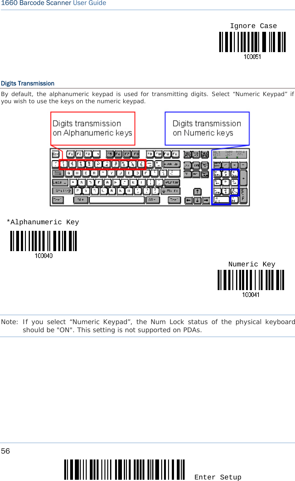
![47 Update Chapter 2 錯誤! 使用 [常用] 索引標籤將 Heading 1 套用到您想要在此處顯示的文字。 Digits Transmission By default, the alphanumeric keypad is used for transmitting digits. Select “Numeric Keypad” if you wish to use the keys on the numeric keypad. Note: If you select “Numeric Keypad”, the Num Lock status of the physical keyboard should be "ON". This setting is not supported on PDAs. Ignore Case*Alphanumeric Key Numeric Key](https://usermanual.wiki/CipherLab/3610/User-Guide-1096354-Page-59.png)
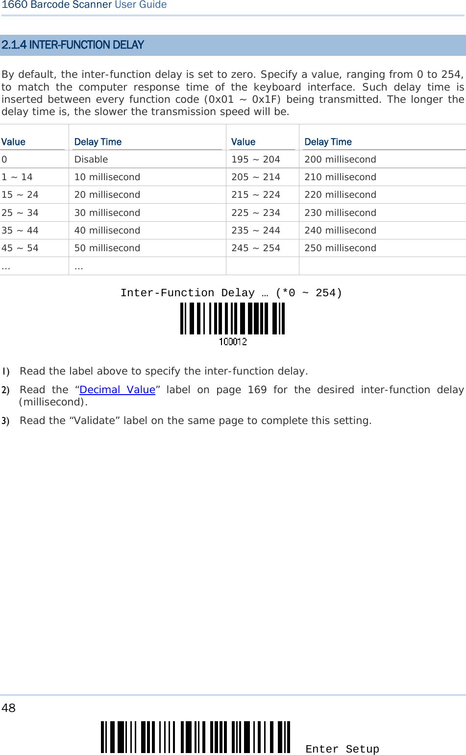
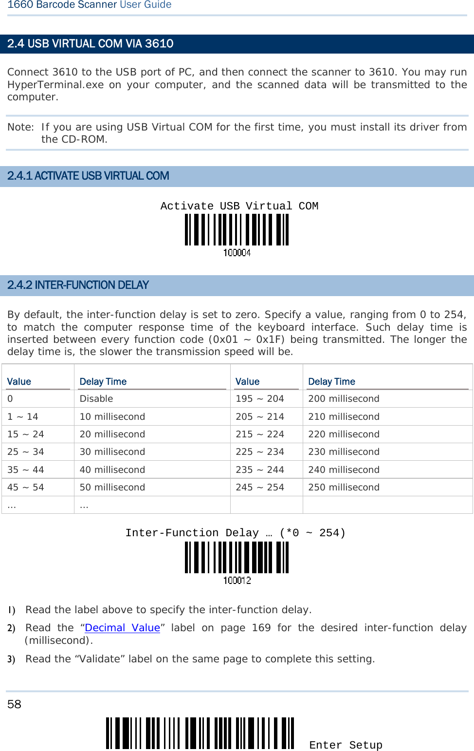
![49 Update Chapter 2 錯誤! 使用 [常用] 索引標籤將 Heading 1 套用到您想要在此處顯示的文字。 2.2 BT SPP For BT SPP, refer to Chapter 3 – Setting up a WPAN Connection for related connection settings. 2.2.1 ACTIVATE BT SPP 2.2.2 INTER-FUNCTION DELAY By default, the inter-function delay is set to zero. Specify a value, ranging from 0 to 254, to match the computer response time of the keyboard interface. Such delay time is inserted between every function code (0x01 ~ 0x1F) being transmitted. The longer the delay time is, the slower the transmission speed will be. Value Delay Time Value Delay Time 0 Disable 195 ~ 204 200 millisecond 1 ~ 14 10 millisecond 205 ~ 214 210 millisecond 15 ~ 24 20 millisecond 215 ~ 224 220 millisecond 25 ~ 34 30 millisecond 225 ~ 234 230 millisecond 35 ~ 44 40 millisecond 235 ~ 244 240 millisecond 45 ~ 54 50 millisecond 245 ~ 254 250 millisecond … … 1) Read the label above to specify the inter-function delay. 2) Read the “Decimal Value” label on page 169 for the desired inter-function delay (millisecond). 3) Read the “Validate” label on the same page to complete this setting. Activate Bluetooth SPPInter-Function Delay … (*0 ~ 254)](https://usermanual.wiki/CipherLab/3610/User-Guide-1096354-Page-61.png)
![51 Update Chapter 2 錯誤! 使用 [常用] 索引標籤將 Heading 1 套用到您想要在此處顯示的文字。 2.3 USB HID VIA 3610 For USB HID, connect 3610 to the USB port of PC, and then connect the scanner to 3610. Run any text editor on your computer, and the scanned data will be transmitted to the computer. HID Settings Defaults Keyboard Type PCAT (US) Digits Layout Normal Capital Lock Type Normal Capital Lock State Off Alphabets Transmission Case-sensitive Digits Transmission Alphanumeric keypad Inter-Function Delay 0 (ms) Send “NR” to Host Disable 2.3.1 ACTIVATE USB HID & SELECT KEYBOARD TYPE When USB HID interface is activated, you will have to select a keyboard type to complete this setting. By default, BT HID is activated on the 1660 scanner, and the keyboard type is set to PCAT (US). 1) Read the label above to activate USB HID and select a keyboard type. 2) Read the “Decimal Value” label on page 169. Refer to the table below for the number of desired keyboard type. 3) Read the “Validate” label on the same page to complete this setting. Activate USB HID & Select Keyboard Type …](https://usermanual.wiki/CipherLab/3610/User-Guide-1096354-Page-63.png)
![53 Update Chapter 2 錯誤! 使用 [常用] 索引標籤將 Heading 1 套用到您想要在此處顯示的文字。 2.3.3 KEYBOARD SETTINGS Digits Layout Capital Lock Type Capital Lock Setting Alphabets Transmission Digits Transmission Note: USB HID does not support these functions on PDAs – (1) Capital Lock Setting: Auto Detection (2) Digits Transmission: Numeric Key Digits Layout Select a proper layout that matches the alphabets layout. The scanner will make adjustments according to this setting. Options Description Normal Depends on the [Shift] key or [Shift Lock] setting Lower Row For QWERTY or QWERTZ keyboard Upper Row For AZERTY keyboard Note: This setting is to be used with the Character Substitution setting when support to certain keyboard types (languages) is unavailable but required. Capital Lock Type & Setting In order to send the alphabets with correct case, the scanner needs to know the status of Caps Lock on the keyboard. Incorrect settings may result in reversed case of the alphabets being transmitted. *Normal Lower Row Upper Row](https://usermanual.wiki/CipherLab/3610/User-Guide-1096354-Page-65.png)
![55 Update Chapter 2 錯誤! 使用 [常用] 索引標籤將 Heading 1 套用到您想要在此處顯示的文字。 Alphabets Transmission By default, the alphabets transmission is case-sensitive, meaning that the alphabets will be transmitted according to their original case, the status of Caps Lock on the keyboard, as well as the Capital Lock setting. Select [Ignore Case] to have alphabets transmitted according to the status of Caps Lock on the keyboard only. Auto DetectionCapital Lock ON *Case-sensitive](https://usermanual.wiki/CipherLab/3610/User-Guide-1096354-Page-67.png)
![57 Update Chapter 2 錯誤! 使用 [常用] 索引標籤將 Heading 1 套用到您想要在此處顯示的文字。 2.3.4 INTER-FUNCTION DELAY By default, the inter-function delay is set to zero. Specify a value, ranging from 0 to 254, to match the computer response time of the keyboard interface. Such delay time is inserted between every function code (0x01 ~ 0x1F) being transmitted. The longer the delay time is, the slower the transmission speed will be. Value Delay Time Value Delay Time 0 Disable 195 ~ 204 200 millisecond 1 ~ 14 10 millisecond 205 ~ 214 210 millisecond 15 ~ 24 20 millisecond 215 ~ 224 220 millisecond 25 ~ 34 30 millisecond 225 ~ 234 230 millisecond 35 ~ 44 40 millisecond 235 ~ 244 240 millisecond 45 ~ 54 50 millisecond 245 ~ 254 250 millisecond … … 1) Read the label above to specify the inter-function delay. 2) Read the “Decimal Value” label on page 169 for the desired inter-function delay (millisecond). 3) Read the “Validate” label on the same page to complete this setting. Inter-Function Delay … (*0 ~ 254)](https://usermanual.wiki/CipherLab/3610/User-Guide-1096354-Page-69.png)
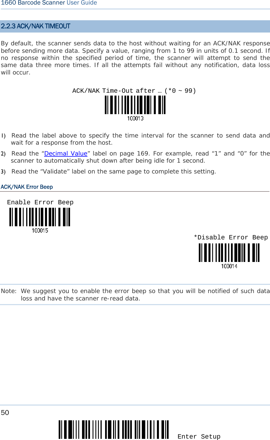
![59 Update Chapter 2 錯誤! 使用 [常用] 索引標籤將 Heading 1 套用到您想要在此處顯示的文字。 2.4.3 ACK/NAK TIMEOUT By default, the scanner sends data to the host without waiting for an ACK/NAK response before sending more data. Specify a value, ranging from 1 to 99 in units of 0.1 second. If no response within the specified period of time, the scanner will attempt to send the same data three more times. If all the attempts fail without any notification, data loss will occur. 1) Read the label above to specify the time interval for the scanner to send data and wait for a response from the host. 2) Read the “Decimal Value” label on page 169. For example, read “1” and “0” for the scanner to automatically shut down after being idle for 1 second. 3) Read the “Validate” label on the same page to complete this setting. ACK/NAK Error Beep Note: We suggest you to enable the error beep so that you will be notified of such data loss and have the scanner re-read data. ACK/NAK Time-Out after … (*0 ~ 99)Enable Error Beep *Disable Error Beep](https://usermanual.wiki/CipherLab/3610/User-Guide-1096354-Page-71.png)

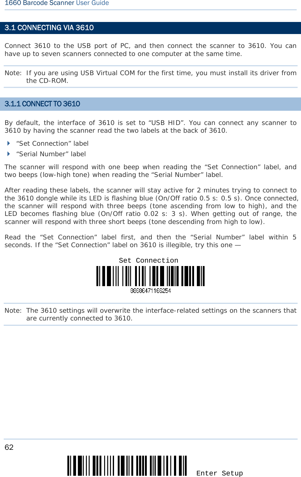
![63 Update Chapter 3 錯誤! 使用 [常用] 索引標籤將 Heading 1 套用到您想要在此處顯示的文字。 3.1.2 CHANGE INTERFACE If you want to change the interface 3610, use one of the connected scanners to configure the interface-related settings and it will pass the new settings to 3610, which will then initialize and pass the settings to any other connected scanners. 1) Have the scanners read the “Set Connection” and “Serial Number” labels at the back of 3610. 2) Within two minutes, connect 3610 to the USB port of PC. For USB Virtual COM, you may need to install its driver first! 3) The scanners will connect to your computer via 3610. 4) Have one scanner read the “Enter Setup” label to enter the configuration mode. 5) Have the scanner read the desired interface label and configure its related settings – “Activate USB HID & Select Keyboard Type” “Activate USB Virtual COM” 6) Have the scanner read the “Update” label to exit the configuration mode. 7) After the scanner resumes connection with 3610, it will pass the interface-related settings to 3610. 8) Upon receipt of the new settings, 3610 will initialize itself. 9) Updated with new settings, 3610 will pass the settings to other connected scanners.](https://usermanual.wiki/CipherLab/3610/User-Guide-1096354-Page-75.png)
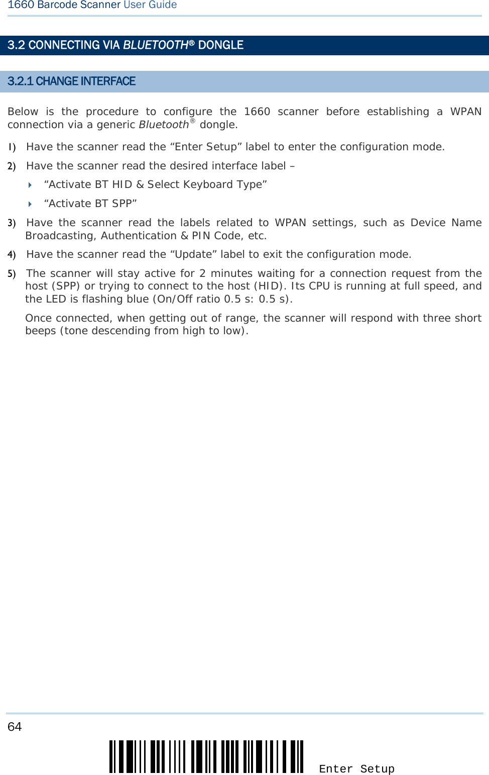
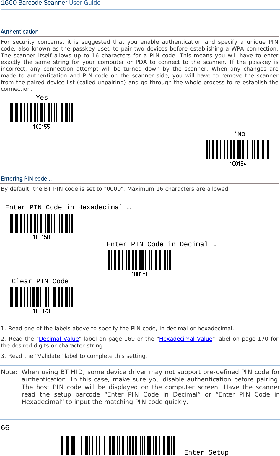
![65 Update Chapter 3 錯誤! 使用 [常用] 索引標籤將 Heading 1 套用到您想要在此處顯示的文字。 3.2.2 CONFIGURE RELATED SETTINGS Sniff Mode (Power-saving) By default, this feature is enabled, meaning the scanner will listen to the wireless network at a reduced rate. Note: When connecting more than two 1660 scanners to a notebook computer or PDA with Bluetooth® wireless technology, we suggest you to disable the power-saving setting for a more reliable connection. Device Name Broadcasting The scanner can be configured to hide itself from other devices equipped with Bluetooth® wireless technology. Simply disable the device name broadcasting setting so that it won’t be discovered by any other computer or PDA. However, broadcasting must be enabled for establishing an initial connection with the scanner. For example, you can disable device name broadcasting after successfully connecting the scanner to WorkStation1. Such connection will be maintained automatically unless the scanner is removed from the paired device list (called unpairing) by WorkStation1 or any changes made to authentication and the PIN code. If you want WorkStation2 to connect to the scanner, you will have to enable device name broadcasting first. Note: By default, device name broadcasting is enabled (which is required for initial connection). *Enable Disable *Enable Disable](https://usermanual.wiki/CipherLab/3610/User-Guide-1096354-Page-77.png)
![67 Update Chapter 3 錯誤! 使用 [常用] 索引標籤將 Heading 1 套用到您想要在此處顯示的文字。 3.2.3 CONNECT TO DONGLE The procedure goes through associating devices for establishing a WPAN connection, which is pretty much the same except for the software you are using. If your computer is running Microsoft® Windows® XP Service Pack 2 (SP2) or Windows Vista®, you can use the generic software support that Windows® includes, or you can use the driver that the device manufacturer provides. Now, let’s try using the generic software support that Windows® XP Service Pack 2 includes. BT HID Procedure By default, BT HID is activated on the 1660 scanner, and the keyboard type is set to PCAT (US). When BT HID is re-activated, you will have to select a keyboard type to complete this setting. The procedure is the same as for BT SPP. Refer to steps 1~11 below. BT SPP Procedure 1. Turn on the Bluetooth® function on your computer, running Windows XP SP2. 2. Double-click the Bluetooth® icon fro the lower right of the taskbar. Alternatively, you may go to Control Panel > Bluetooth Devices. 3. Click [Add] to search devices nearby.](https://usermanual.wiki/CipherLab/3610/User-Guide-1096354-Page-79.png)
![68 Enter Setup 1660 Barcode Scanner User Guide 4. Turn on the scanner with correct WPAN settings, such as select BT SPP or BT HID, broadcasting enabled, authentication enabled, and PIN code specified, etc. Select the check box of [My device is set up and ready to be found] on your computer. 5. Click [Next].](https://usermanual.wiki/CipherLab/3610/User-Guide-1096354-Page-80.png)
![69 Update Chapter 3 錯誤! 使用 [常用] 索引標籤將 Heading 1 套用到您想要在此處顯示的文字。 6. Wait for a few seconds for the Wizard to search available devices nearby. The scanner will appear with its “serial number” as the device name. You may double-check the “Serial Number” label on the scanner to ensure connecting with the correct scanner. Select the target scanner. If the target scanner does not appear on the list, click [Search Again] to refresh the list. The scanner might enter Suspend Mode now, and you can press the [Trigger] key to have it active again (=discoverable). It will then stay active for 2 minutes and wait for PC to establish a connection. 7. Click [Next].](https://usermanual.wiki/CipherLab/3610/User-Guide-1096354-Page-81.png)
![70 Enter Setup 1660 Barcode Scanner User Guide 8. Enter the passkey for authentication, which must be exactly the same as configured for the scanner. 9. Click [Next]. Wait for a few seconds for Windows to exchange passkeys.](https://usermanual.wiki/CipherLab/3610/User-Guide-1096354-Page-82.png)
![71 Update Chapter 3 錯誤! 使用 [常用] 索引標籤將 Heading 1 套用到您想要在此處顯示的文字。 10. Click [Finish]. Bluetooth SPP Only](https://usermanual.wiki/CipherLab/3610/User-Guide-1096354-Page-83.png)
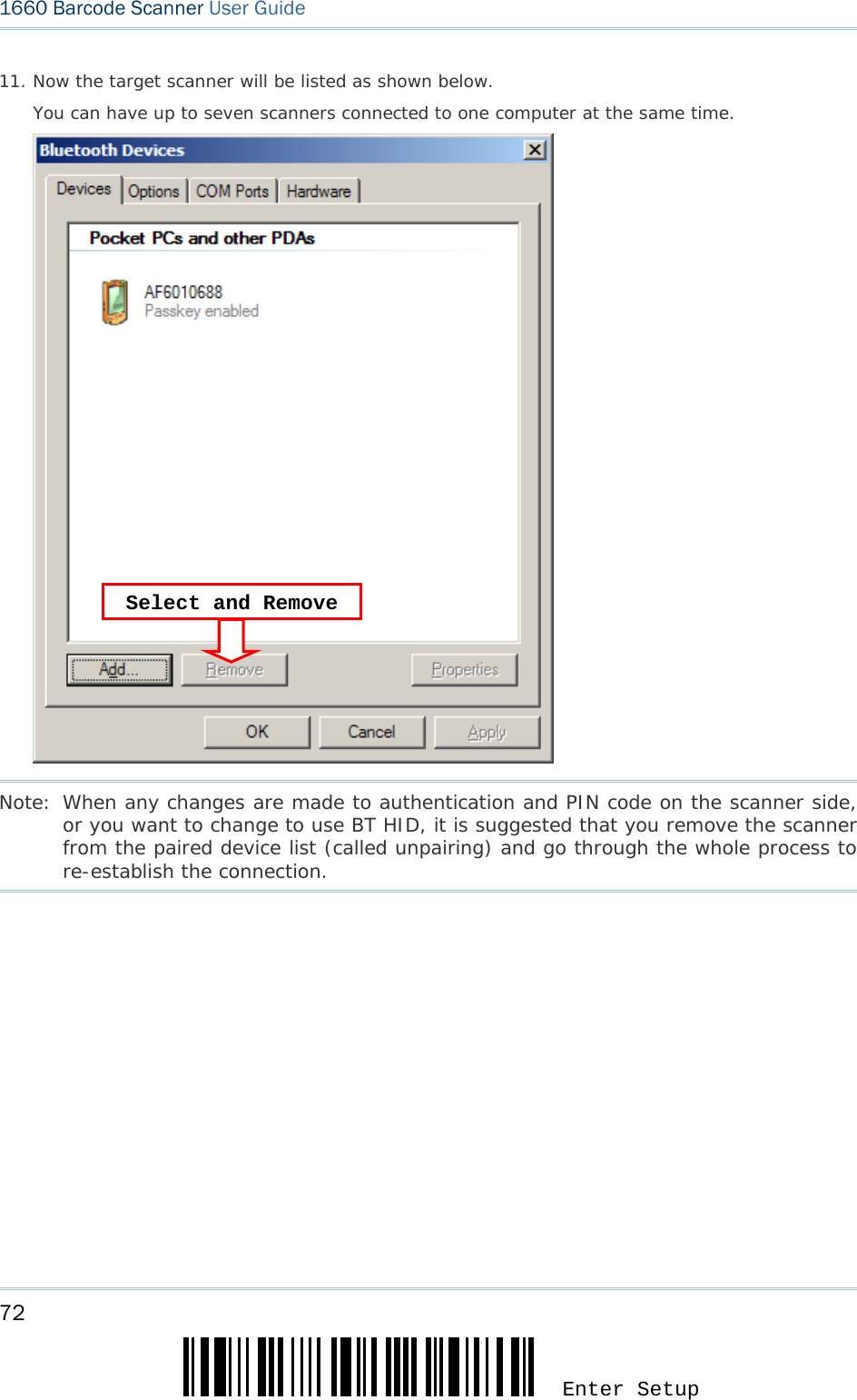
![73 Update Chapter 3 錯誤! 使用 [常用] 索引標籤將 Heading 1 套用到您想要在此處顯示的文字。 12. Run the desired application on your computer, such as HyperTerminal.exe if using BT SPP or Notepad.exe if using BT HID. The status of the scanner listed on the device list will be updated to “Connected”, indicating the WPAN connection is established successfully via the outgoing COM port if using BT SPP. BT SPP Connected BT SPP Disconnected](https://usermanual.wiki/CipherLab/3610/User-Guide-1096354-Page-85.png)

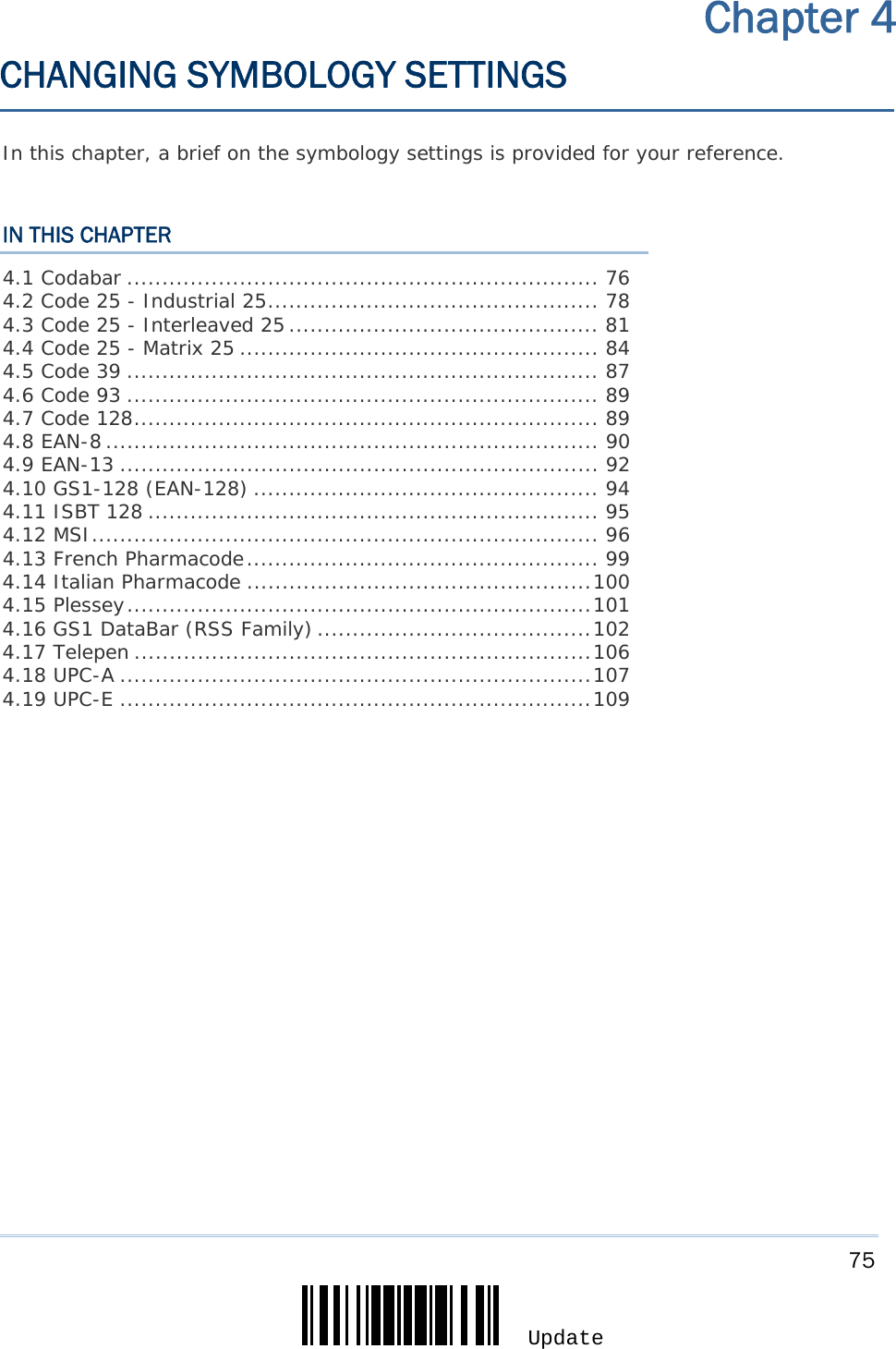
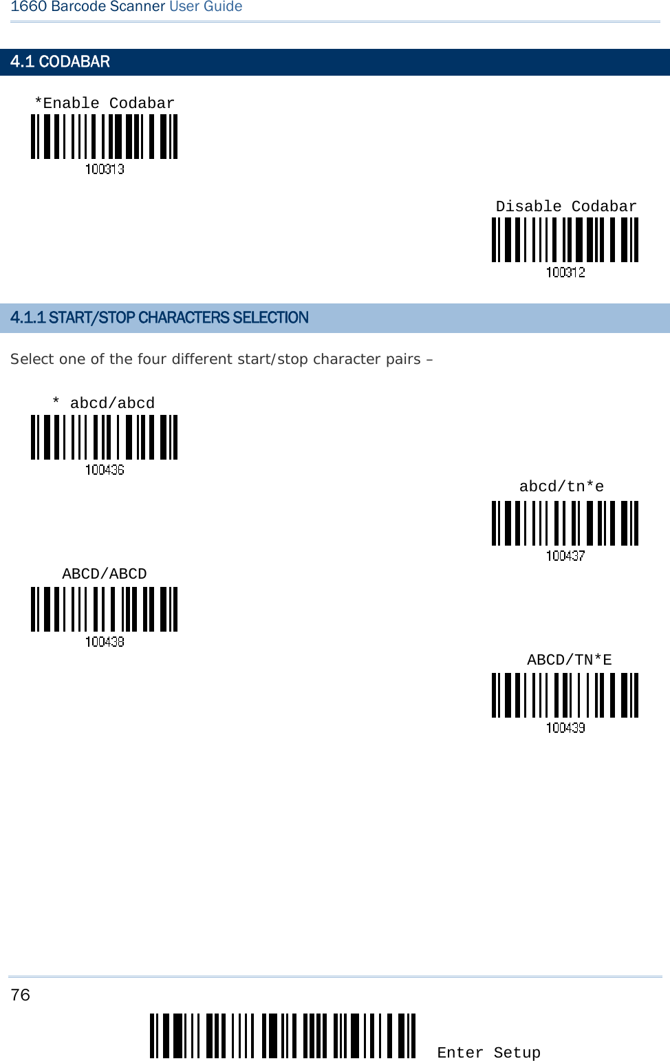
![77 Update Chapter 4 錯誤! 使用 [常用] 索引標籤將 Heading 1 套用到您想要在此處顯示的文字。 4.1.2 START/STOP TRANSMISSION Decide whether or not to include the start/stop characters in the data being transmitted. 4.1.3 CLSI CONVERSION When enabled, the CLSI editing strips the start/stop characters and inserts a space after the first, fifth, and tenth characters of a 14-character Codabar barcode. Note: The 14-character barcode length does not include start/stop characters. *Do Not TransmitTransmit Codabar Start/Stop Characters Apply CLSI Editing *Do Not Apply](https://usermanual.wiki/CipherLab/3610/User-Guide-1096354-Page-89.png)
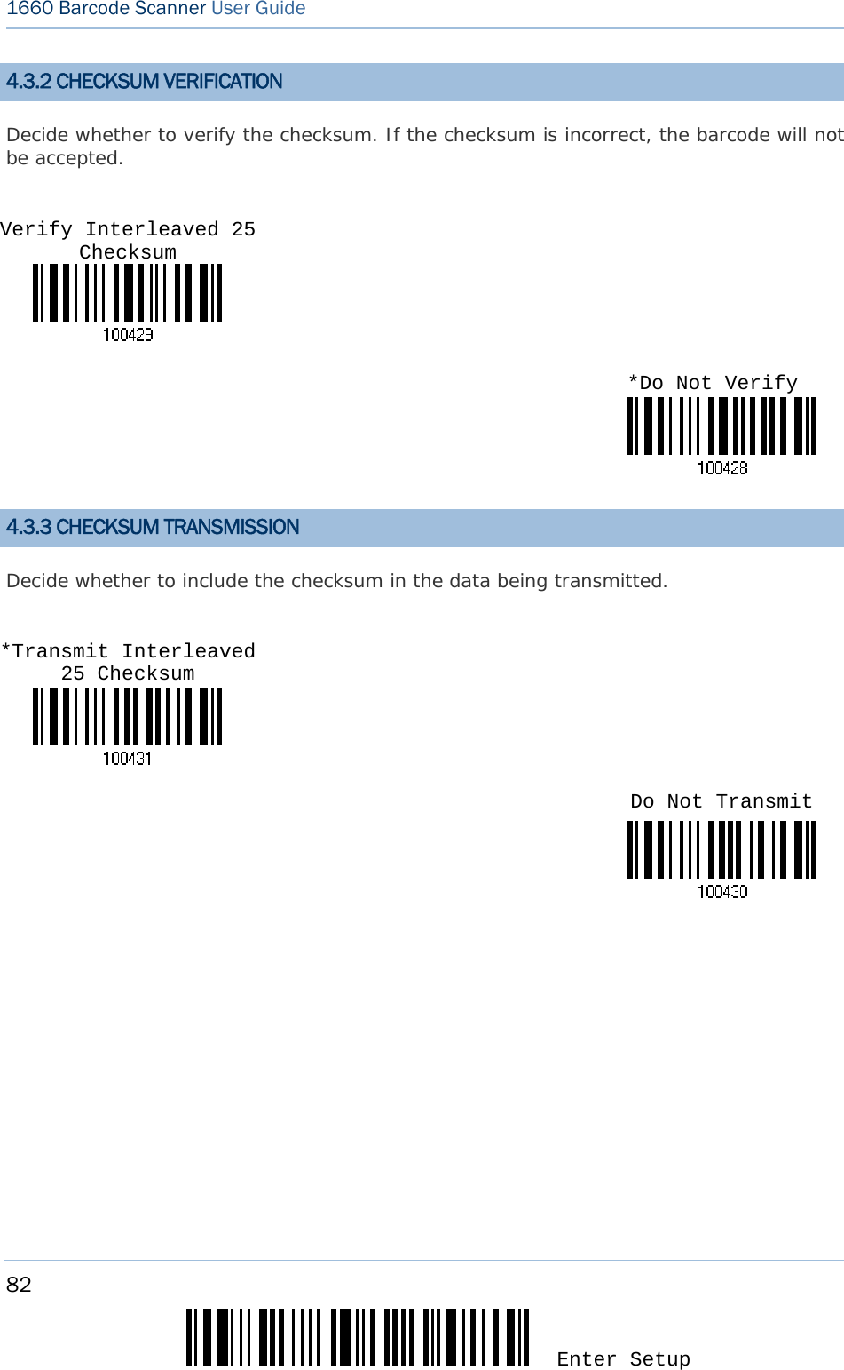
![79 Update Chapter 4 錯誤! 使用 [常用] 索引標籤將 Heading 1 套用到您想要在此處顯示的文字。 4.2.2 CHECKSUM VERIFICATION Decide whether to verify the checksum. If the checksum is incorrect, the barcode will not be accepted. 4.2.3 CHECKSUM TRANSMISSION Decide whether to include the checksum in the data being transmitted. Verify Industrial 25 Checksum *Transmit Industrial 25 Checksum Do Not Transmit*Do Not Verify](https://usermanual.wiki/CipherLab/3610/User-Guide-1096354-Page-91.png)
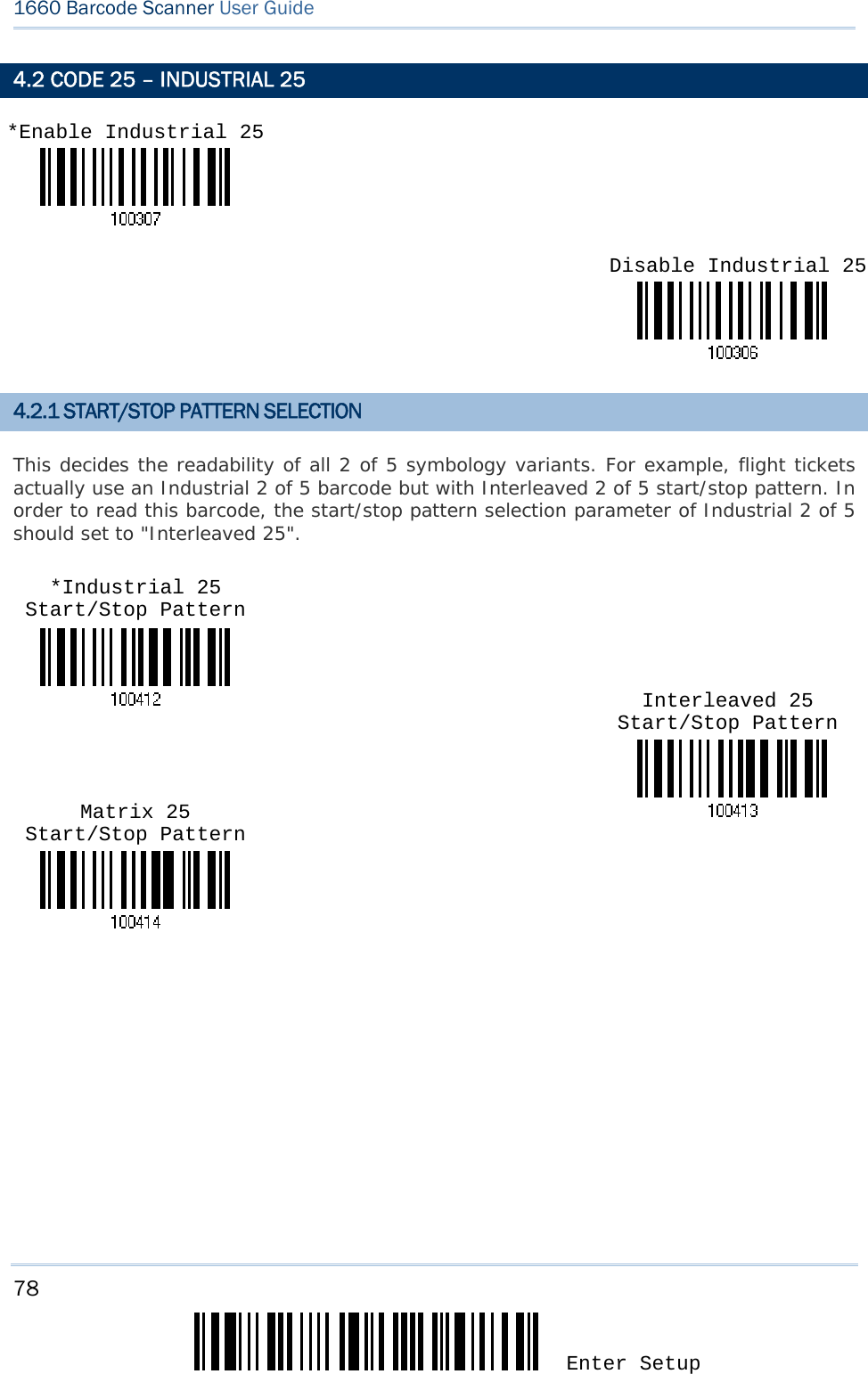
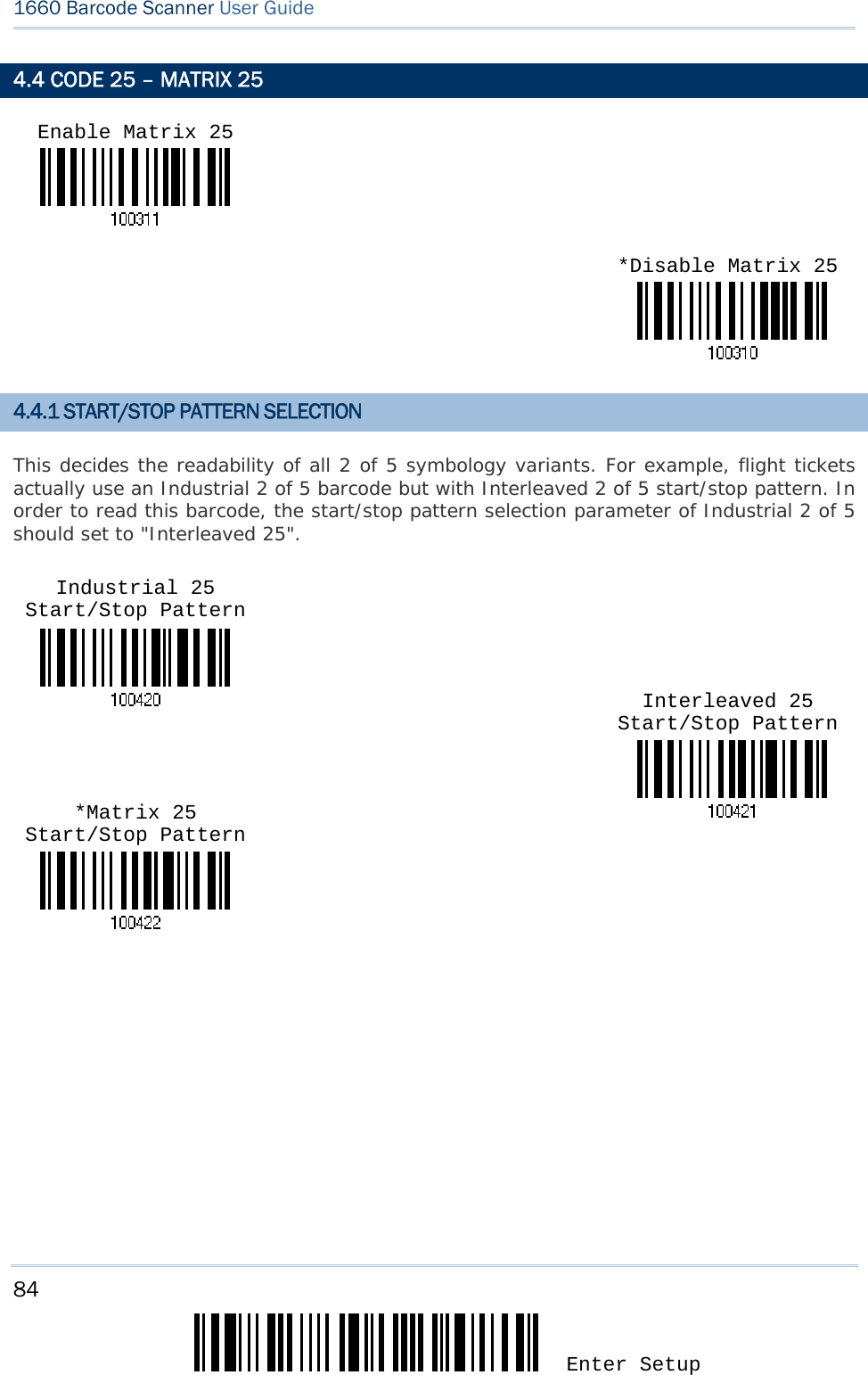
![81 Update Chapter 4 錯誤! 使用 [常用] 索引標籤將 Heading 1 套用到您想要在此處顯示的文字。 4.3 CODE 25 – INTERLEAVED 25 4.3.1 START/STOP PATTERN SELECTION This decides the readability of all 2 of 5 symbology variants. For example, flight tickets actually use an Industrial 2 of 5 barcode but with Interleaved 2 of 5 start/stop pattern. In order to read this barcode, the start/stop pattern selection parameter of Industrial 2 of 5 should set to "Interleaved 25". *Enable Interleaved 25 Disable Interleaved 25Industrial 25 Start/Stop Pattern Matrix 25 Start/Stop Pattern *Interleaved 25 Start/Stop Pattern](https://usermanual.wiki/CipherLab/3610/User-Guide-1096354-Page-93.png)
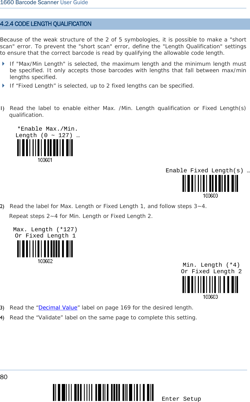
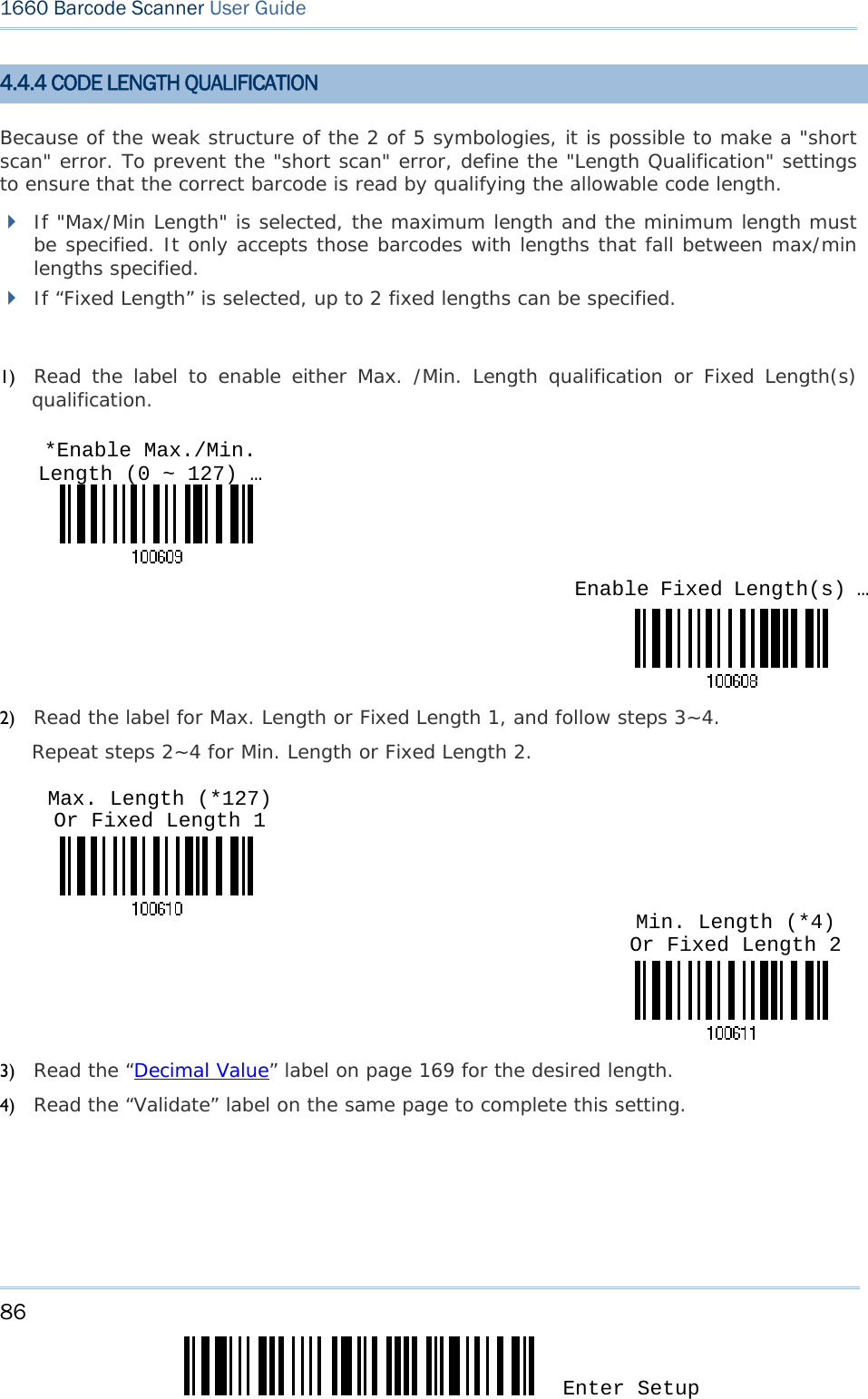
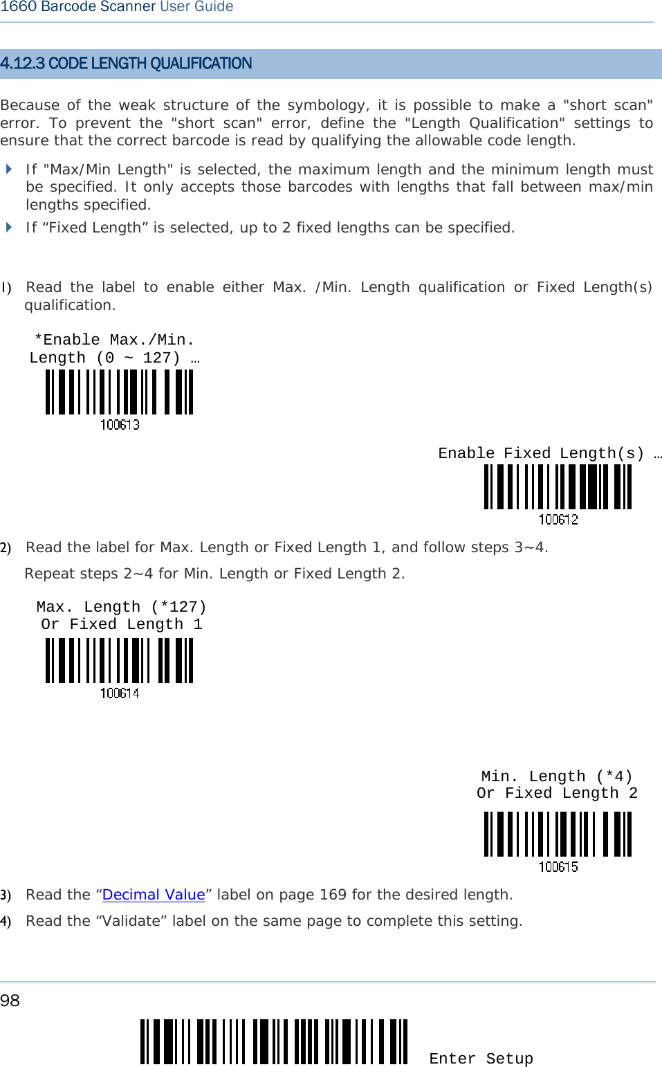
![83 Update Chapter 4 錯誤! 使用 [常用] 索引標籤將 Heading 1 套用到您想要在此處顯示的文字。 4.3.4 CODE LENGTH QUALIFICATION Because of the weak structure of the 2 of 5 symbologies, it is possible to make a "short scan" error. To prevent the "short scan" error, define the "Length Qualification" settings to ensure that the correct barcode is read by qualifying the allowable code length. If "Max/Min Length" is selected, the maximum length and the minimum length must be specified. It only accepts those barcodes with lengths that fall between max/min lengths specified. If “Fixed Length” is selected, up to 2 fixed lengths can be specified. 1) Read the label to enable either Max. /Min. Length qualification or Fixed Length(s) qualification. 2) Read the label for Max. Length or Fixed Length 1, and follow steps 3~4. Repeat steps 2~4 for Min. Length or Fixed Length 2. 3) Read the “Decimal Value” label on page 169 for the desired length. 4) Read the “Validate” label on the same page to complete this setting. Enable Fixed Length(s) …*Enable Max./Min. Length (0 ~ 127) … Max. Length (*126) Or Fixed Length 1 Min. Length (*4) Or Fixed Length 2](https://usermanual.wiki/CipherLab/3610/User-Guide-1096354-Page-95.png)
![85 Update Chapter 4 錯誤! 使用 [常用] 索引標籤將 Heading 1 套用到您想要在此處顯示的文字。 4.4.2 CHECKSUM VERIFICATION Decide whether to verify the checksum. If the checksum is incorrect, the barcode will not be accepted. 4.4.3 CHECKSUM TRANSMISSION Decide whether to include the checksum in the data being transmitted. Verify Matrix 25 Checksum *Transmit Matrix 25 Checksum Do Not Transmit*Do Not Verify](https://usermanual.wiki/CipherLab/3610/User-Guide-1096354-Page-97.png)
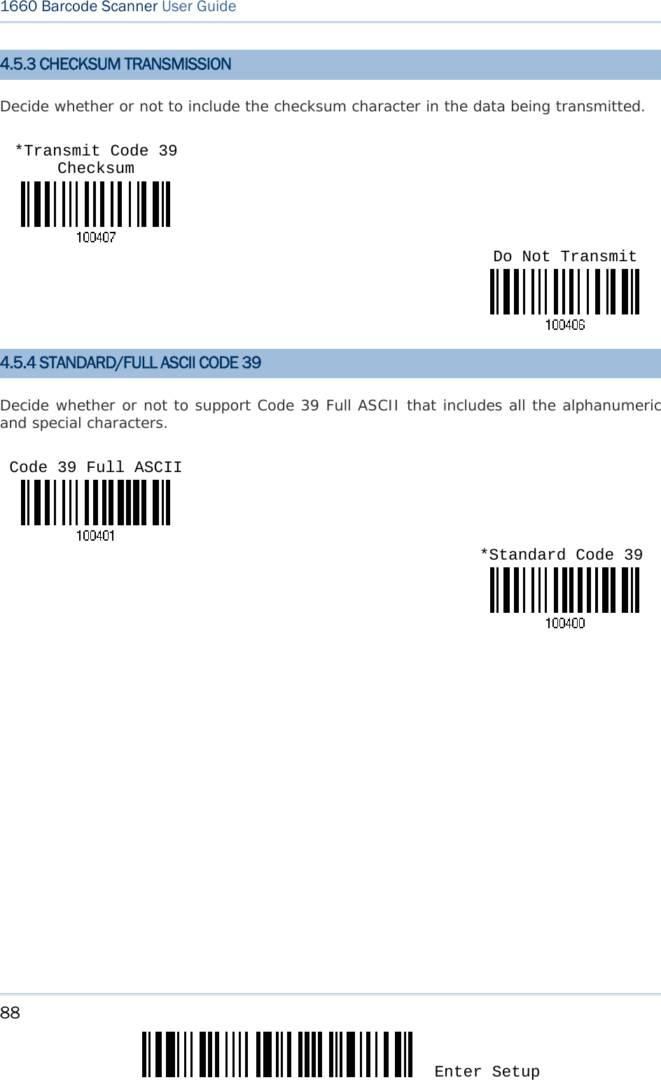
![87 Update Chapter 4 錯誤! 使用 [常用] 索引標籤將 Heading 1 套用到您想要在此處顯示的文字。 4.5 CODE 39 4.5.1 START/STOP TRANSMISSION Decide whether or not to include the start/stop characters in the data being transmitted. 4.5.2 CHECKSUM VERIFICATION Decide whether or not to perform checksum verification when decoding barcodes. If enabled and the checksum found incorrect, the barcode will not be accepted. *Enable Code 39 Disable Code 39Transmit Code 39 Start/Stop Characters *Do Not TransmitVerify Code 39 Checksum *Do Not Verify](https://usermanual.wiki/CipherLab/3610/User-Guide-1096354-Page-99.png)
![89 Update Chapter 4 錯誤! 使用 [常用] 索引標籤將 Heading 1 套用到您想要在此處顯示的文字。 4.6 CODE 93 You can only configure the scanner to read this symbology or not. 4.7 CODE 128 You can only configure the scanner to read this symbology or not. *Enable Code 93 Disable Code 93*Enable Code 128 Disable Code 128](https://usermanual.wiki/CipherLab/3610/User-Guide-1096354-Page-101.png)
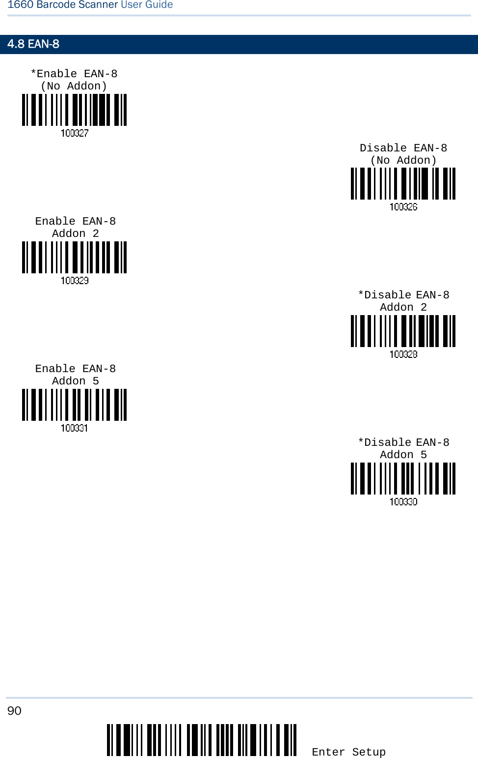
![91 Update Chapter 4 錯誤! 使用 [常用] 索引標籤將 Heading 1 套用到您想要在此處顯示的文字。 4.8.1 CONVERT TO EAN-13 Decide whether or not to expand the read EAN-8 barcode into EAN-13. If enabled, the next processing will follow the parameters configured for EAN-13. 4.8.2 CHECKSUM TRANSMISSION Decide whether or not to include the checksum character in the data being transmitted. Convert EAN-8 to EAN-13 *Transmit EAN-8 Checksum Do Not Transmit*Do Not Convert](https://usermanual.wiki/CipherLab/3610/User-Guide-1096354-Page-103.png)
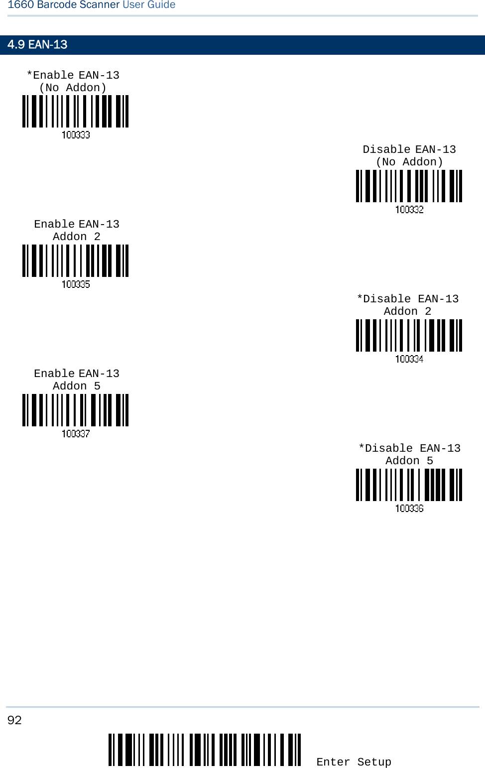
![93 Update Chapter 4 錯誤! 使用 [常用] 索引標籤將 Heading 1 套用到您想要在此處顯示的文字。 4.9.1 ISBN CONVERSION Decide whether or not to convert the EAN-13 barcode, starting with 978 and 979, to ISBN. 4.9.2 ISSN CONVERSION Decide whether or not to convert the EAN-13 barcode, starting with 977 to ISSN. 4.9.3 CHECKSUM TRANSMISSION Decide whether or not to include the checksum character in the data being transmitted. Convert EAN-13 to ISBN *Do Not Convert*Do Not ConvertConvert EAN-13 to ISSN Do Not Transmit*Transmit EAN-13 Checksum](https://usermanual.wiki/CipherLab/3610/User-Guide-1096354-Page-105.png)
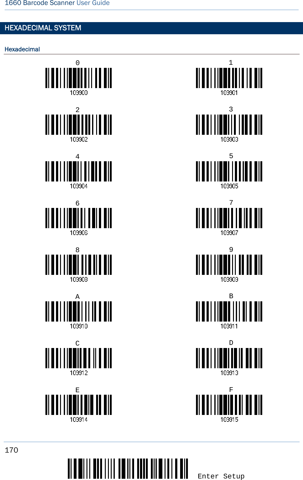
![94 Enter Setup 1660 Barcode Scanner User Guide 4.10 GS1-128 (EAN-128) 4.10.1 CODE ID TRANSMISSION Decide whether or not to include the Code ID (“]C1”) in the data being transmitted. 4.10.2 FIELD SEPARATOR (GS CHARACTER) Decide whether or not to apply a field separator (to convert the FNC1 control character to human readable character). 1) Read the label above to enable field separator. 2) Read the “Hexadecimal Value” label on page 170 for the desired character string. 3) Read the “Validate” label to complete this setting. Enable EAN-128*Disable EAN-128Transmit EAN-128 Code ID *Do Not TransmitEnable Field Separator …](https://usermanual.wiki/CipherLab/3610/User-Guide-1096354-Page-106.png)
![95 Update Chapter 4 錯誤! 使用 [常用] 索引標籤將 Heading 1 套用到您想要在此處顯示的文字。 Note: EAN-128 barcodes start with the FNC1 control character to distinguish themselves from other uses of Code 128. FNC1 is also used to separate data fields in the EAN-128 barcodes. 4.11 ISBT 128 You can only configure the scanner to read this symbology or not. Enable ISBT 128 *Disable ISBT 128](https://usermanual.wiki/CipherLab/3610/User-Guide-1096354-Page-107.png)
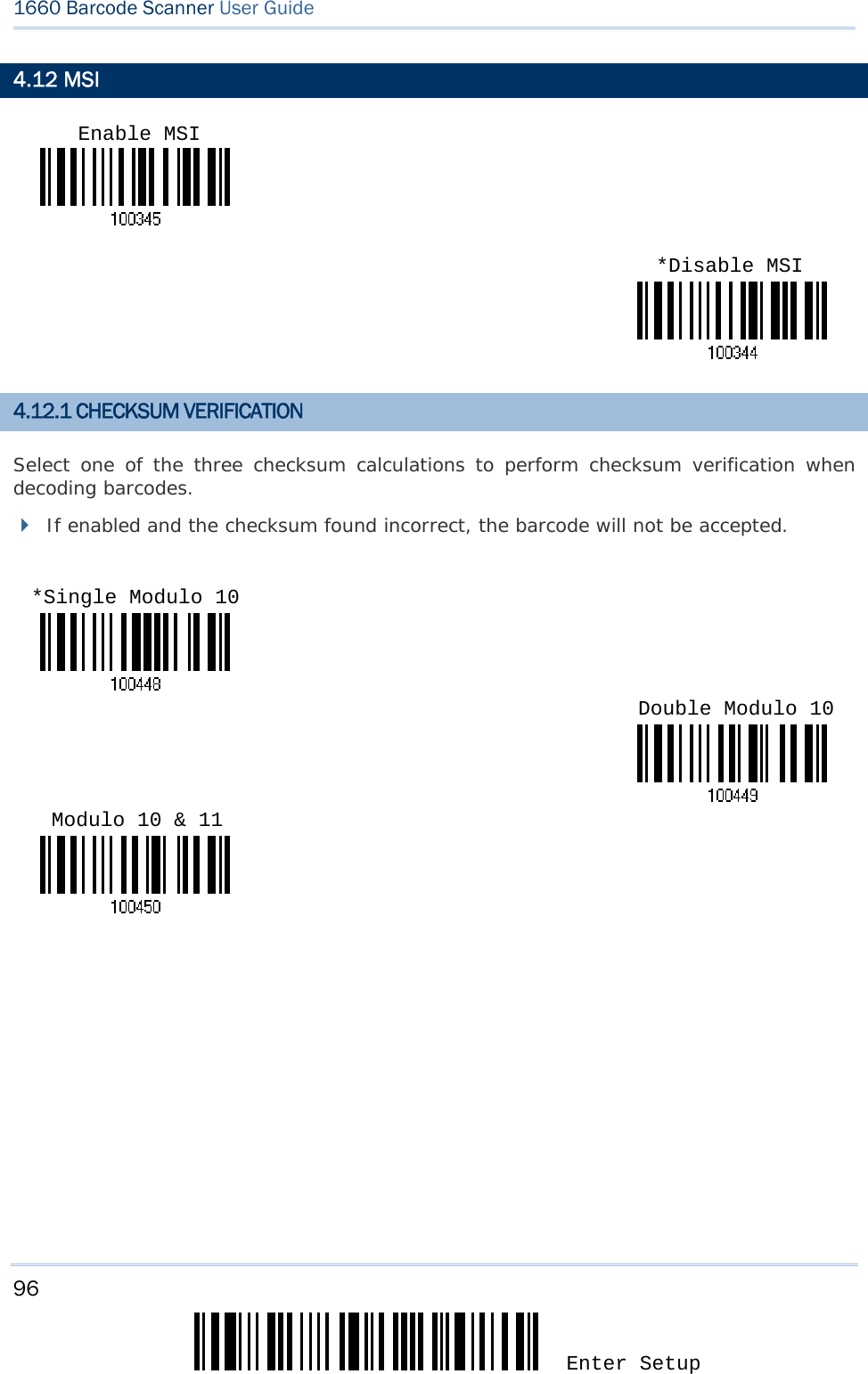
![97 Update Chapter 4 錯誤! 使用 [常用] 索引標籤將 Heading 1 套用到您想要在此處顯示的文字。 4.12.2 CHECKSUM TRANSMISSION Decide whether or not to include the checksum character in the data being transmitted. *Last Digit Not Transmitted Both Digits Not Transmitted Both Digits Transmitted](https://usermanual.wiki/CipherLab/3610/User-Guide-1096354-Page-109.png)
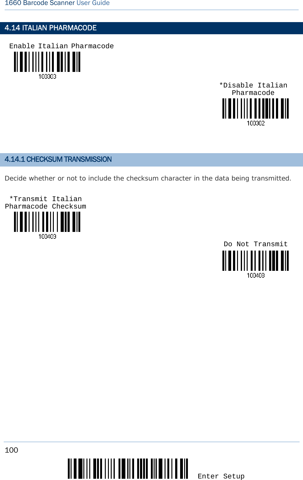
![99 Update Chapter 4 錯誤! 使用 [常用] 索引標籤將 Heading 1 套用到您想要在此處顯示的文字。 4.13 FRENCH PHARMACODE 4.13.1 CHECKSUM TRANSMISSION Decide whether or not to include the checksum character in the data being transmitted. Enable French Pharmacode *Disable French Pharmacode *Transmit French Pharmacode Checksum Do Not Transmit](https://usermanual.wiki/CipherLab/3610/User-Guide-1096354-Page-111.png)
![101 Update Chapter 4 錯誤! 使用 [常用] 索引標籤將 Heading 1 套用到您想要在此處顯示的文字。 4.15 PLESSEY 4.15.1 CONVERT TO UK PLESSEY Decide whether or not to change each occurrence of the character 'A' to character 'X' in the decoded data. 4.15.2 CHECKSUM TRANSMISSION Decide whether or not to include the checksum characters (two digits) in the data being transmitted. Enable Plessey*Disable PlesseyConvert to UK Plessey *Do Not Convert*Transmit Plessey Checksum Do Not Transmit](https://usermanual.wiki/CipherLab/3610/User-Guide-1096354-Page-113.png)
![102 Enter Setup 1660 Barcode Scanner User Guide 4.16 GS1 DATABAR (RSS FAMILY) 4.16.1 CODE ID SELECTION Select a desired Code ID to use – RSS Code ID “]e0“ or EAN-128 Code ID “]C1”. 4.16.2 GS1 DATABAR OMNIDIRECTIONAL (RSS-14) Code ID Transmission Decide whether or not to include the Code ID in the data being transmitted. Enable RSS-14 & RSS Expanded *Disable RSS-14 & RSS Expanded “]C1” for RSS Code ID “]e0” for RSS Code ID (Default) *Transmit RSS-14 Code ID Do Not Transmit](https://usermanual.wiki/CipherLab/3610/User-Guide-1096354-Page-114.png)
![103 Update Chapter 4 錯誤! 使用 [常用] 索引標籤將 Heading 1 套用到您想要在此處顯示的文字。 Application ID Transmission Decide whether or not to include the Application ID ("01") in the data being transmitted. Checksum Transmission Decide whether or not to include the check digit in the data being transmitted. 4.16.3 GS1 DATABAR EXPANDED (RSS EXPANDED) Enable RSS-14 & RSS Expanded *Disable RSS-14 & RSS Expanded *Transmit RSS-14 Application ID Do Not Transmit*Transmit RSS-14 Checksum Do Not Transmit](https://usermanual.wiki/CipherLab/3610/User-Guide-1096354-Page-115.png)
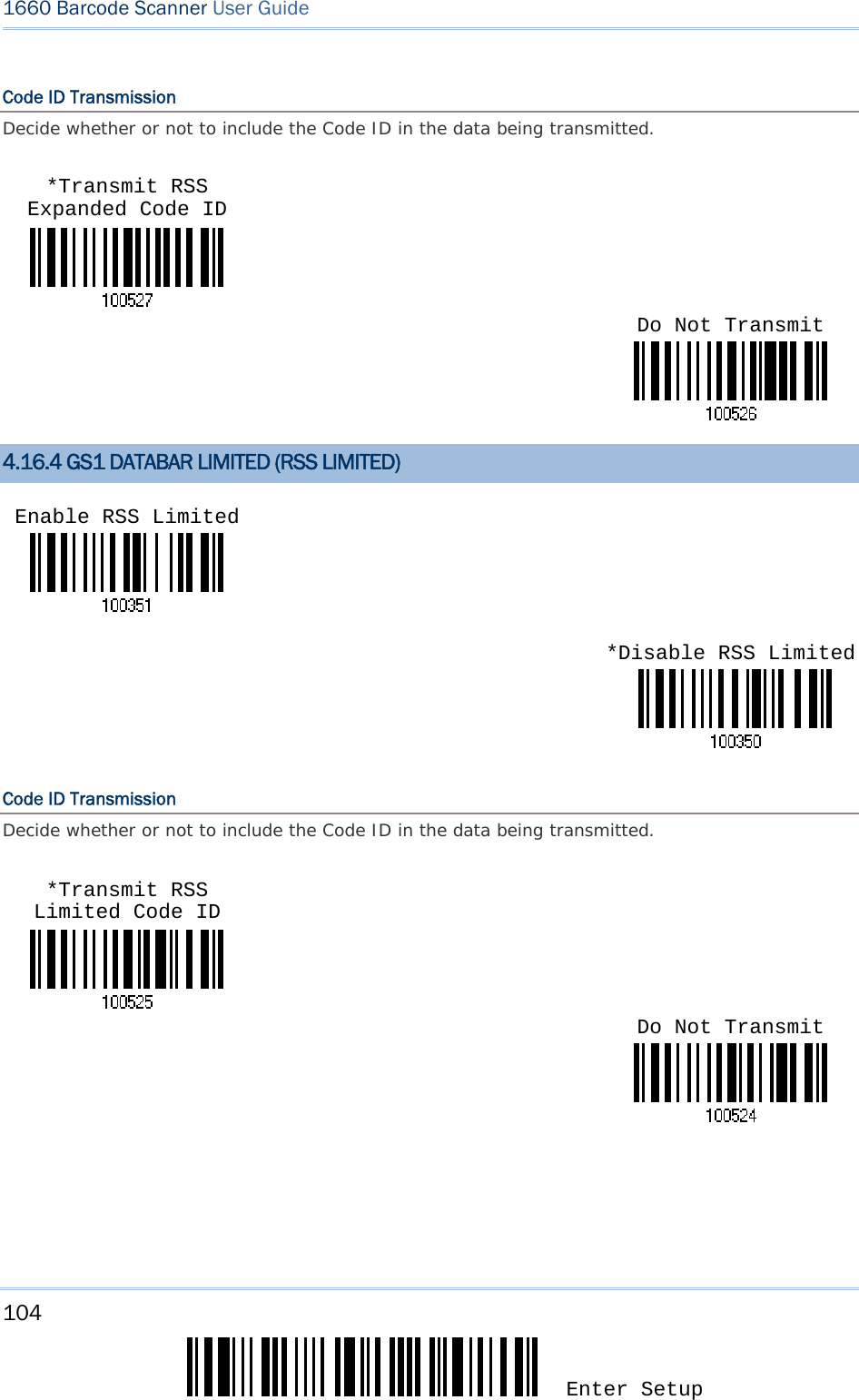
![105 Update Chapter 4 錯誤! 使用 [常用] 索引標籤將 Heading 1 套用到您想要在此處顯示的文字。 Application ID Transmission Decide whether or not to include the Application ID ("01") in the data being transmitted. Checksum Transmission Decide whether or not to include the check digit in the data being transmitted. *Transmit RSS Limited Application ID Do Not Transmit*Transmit RSS Limited Checksum Do Not Transmit](https://usermanual.wiki/CipherLab/3610/User-Guide-1096354-Page-117.png)
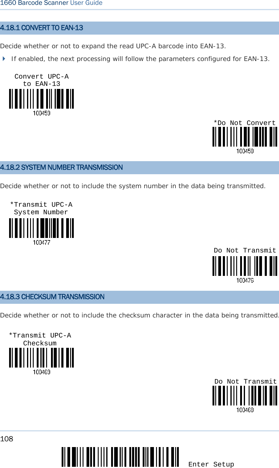
![107 Update Chapter 4 錯誤! 使用 [常用] 索引標籤將 Heading 1 套用到您想要在此處顯示的文字。 4.18 UPC-A Disable UPC-A (No Addon) *Disable UPC-A Addon 2 *Disable UPC-A Addon 5 Enable UPC-A Addon 2 Enable UPC-A Addon 5 *Enable UPC-A (No Addon)](https://usermanual.wiki/CipherLab/3610/User-Guide-1096354-Page-119.png)
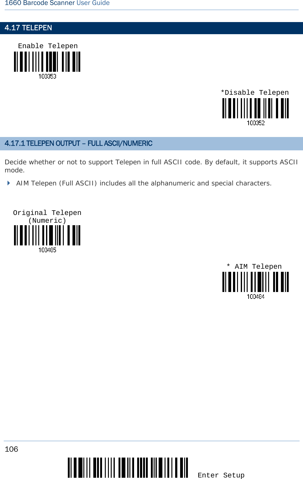
![109 Update Chapter 4 錯誤! 使用 [常用] 索引標籤將 Heading 1 套用到您想要在此處顯示的文字。 4.19 UPC-E Disable UPC-E (No Addon) *Disable UPC-E Addon 2 *Disable UPC-E Addon 5 Enable UPC-E Addon 2 Enable UPC-E Addon 5 *Enable UPC-E (No Addon)](https://usermanual.wiki/CipherLab/3610/User-Guide-1096354-Page-121.png)
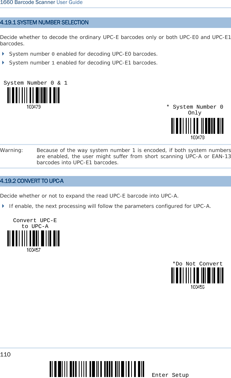
![111 Update Chapter 4 錯誤! 使用 [常用] 索引標籤將 Heading 1 套用到您想要在此處顯示的文字。 4.19.3 SYSTEM NUMBER TRANSMISSION Decide whether or not to include the system number in the data being transmitted. 4.19.4 CHECKSUM TRANSMISSION Decide whether or not to include the checksum character in the data being transmitted. Do Not Transmit*Transmit UPC-E Checksum *Do Not TransmitTransmit UPC-E System Number](https://usermanual.wiki/CipherLab/3610/User-Guide-1096354-Page-123.png)
![113 Update You may configure in which format the collected data will be output to the host computer. Barcode read by the scanner will be processed in the following sequence – 1) Perform character substitution on the data scanned. 2) Add Code ID and Length Code to the front of the data:[Code ID][Length Code][Data] 3) Process the whole data in step 2 with user formats. Data is now divided into fields by user specified rules. Refer to Chapter 6 Applying Formats for Data Editing. 4) Add Prefix Code and Suffix Code before transmission:[Prefix Code][Processed Data][Suffix Code] IN THIS CHAPTER 5.1 Letter Case .............................................................. 113 5.2 Character Substitution ............................................... 114 5.3 Prefix/Suffix Code ..................................................... 120 5.4 Code ID ................................................................... 121 5.5 Length Code ............................................................ 125 5.6 Multi-Barcode Editor .................................................. 128 5.1 LETTER CASE By default, the alphabets transmission is case-sensitive, meaning that the alphabets will be transmitted according to their original case. Ignoring the original letter case, select [Upper Case] to output data in upper case only; otherwise, select [Lower Case] to output data in lower case only. Chapter 5 DEFINING OUTPUT FORMAT *Normal Upper Case Lower Case](https://usermanual.wiki/CipherLab/3610/User-Guide-1096354-Page-125.png)
![114 Enter Setup 1660 Barcode Scanner User Guide 5.2 CHARACTER SUBSTITUTION Character substitution is performed on every occurrence of the first character specified. If only one character is specified, every occurrence of that character in the barcode will be taken away. The first character will be replaced by the second character(s). Up to three sets of character substitution can be configured. Note: The character substitution is performed only on the barcode itself and before the processing of editing formats. It is not applicable to the Prefix/Suffix Code, Code ID, Length Code, or any Additional Field. 5.2.1 SELECT A SET FOR CHARACTER SUBSTITUION 1) Read the label above to enable character substitution by set. For example, have the scanner read the “Set 1” label to configure the first set of character substitution. The scanner will respond with one short beep, high tone, to indicate more setup labels are required. 2) Read the “Hexadecimal Value” label on page 170 for the desired character string. For example, have the scanner read (1) “3”, “0”, “2” and “D” to replace the character [0] with a dash [-] for Set 1, and (2) “3”, “0”, “2”, “D”, “3” and “0”to replace the character [0] with a dash [- 0] for Set 2. 3) Read the “Validate” label to complete this setting. (The defined set or sets will be applied to all symbologies by default.) Configure Set 1 Configure Set 2Configure Set 3](https://usermanual.wiki/CipherLab/3610/User-Guide-1096354-Page-126.png)
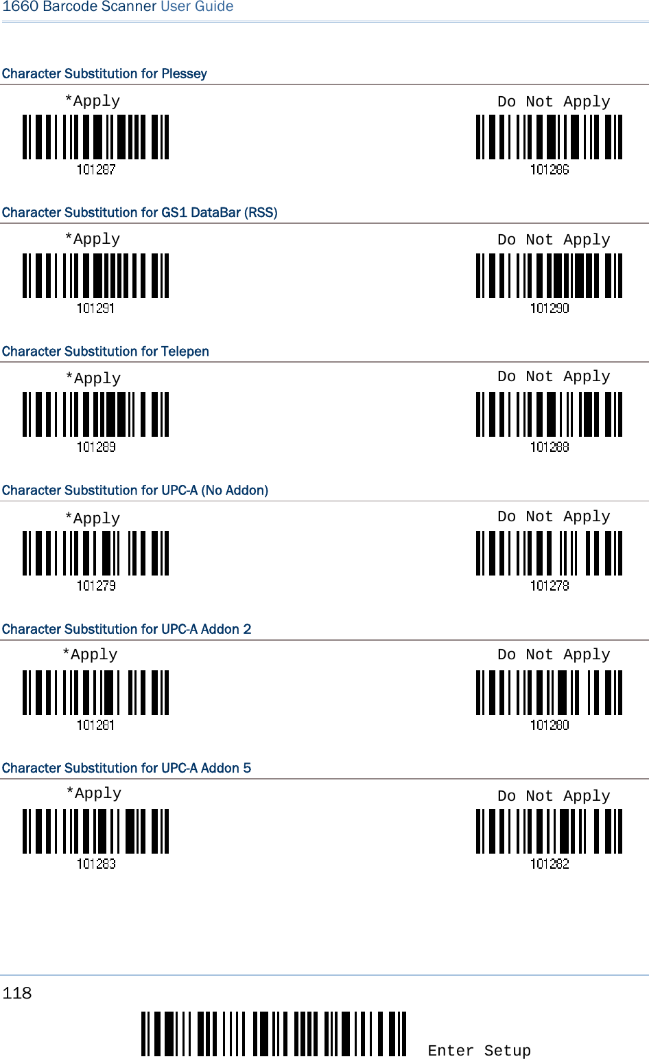
![115 Update Chapter 5 錯誤! 使用 [常用] 索引標籤將 Heading 1 套用到您想要在此處顯示的文字。 5.2.2 SYMBOLOGIES FOR CHARACTER SUBSTITUTION (ALL 3 SETS) By default character substitution will be performed on all symbologies. If the character substitution is not desired with one or more symbologies, read the “Do Not Apply” label for each undesired symbologies and all the three sets will be ignored for them. Character Substitution for Codabar Character Substitution for Code 39 Character Substitution for Code 93 Character Substitution for Code 128 Character Substitution for GS1-128 (EAN-128) *Apply Do Not Apply*Apply Do Not Apply*Apply Do Not Apply*Apply Do Not Apply*Apply Do Not Apply](https://usermanual.wiki/CipherLab/3610/User-Guide-1096354-Page-127.png)
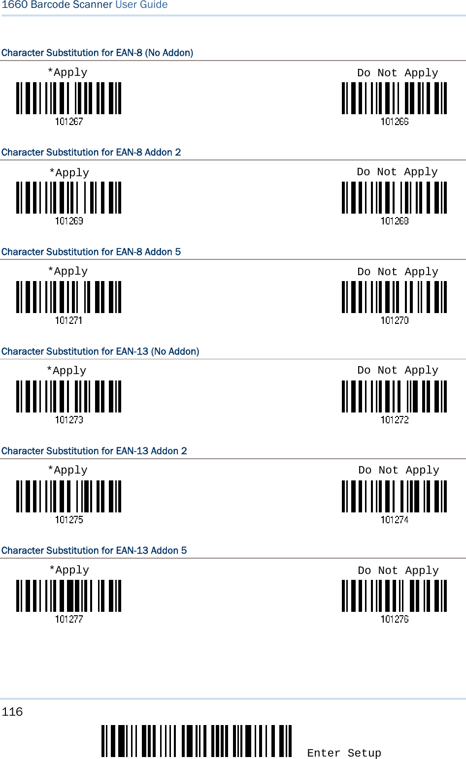
![117 Update Chapter 5 錯誤! 使用 [常用] 索引標籤將 Heading 1 套用到您想要在此處顯示的文字。 Character Substitution for French Pharmacode Character Substitution for Italian Pharmacode Character Substitution for Industrial 25 Character Substitution for Interleaved 25 Character Substitution for Matrix 25 Character Substitution for MSI *Apply Do Not Apply*Apply Do Not Apply*Apply Do Not Apply*Apply Do Not Apply*Apply Do Not Apply*Apply Do Not Apply](https://usermanual.wiki/CipherLab/3610/User-Guide-1096354-Page-129.png)
![119 Update Chapter 5 錯誤! 使用 [常用] 索引標籤將 Heading 1 套用到您想要在此處顯示的文字。 Character Substitution for UPC-E (No Addon) Character Substitution for UPC-E Addon 2 Character Substitution for UPC-E Addon 5 *Apply Do Not Apply*Apply Do Not Apply*Apply Do Not Apply](https://usermanual.wiki/CipherLab/3610/User-Guide-1096354-Page-131.png)
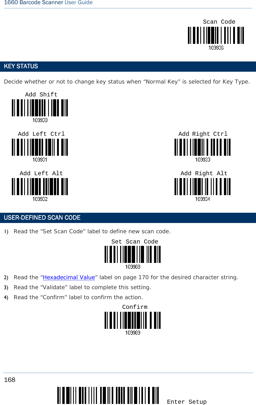
![120 Enter Setup 1660 Barcode Scanner User Guide 5.3 PREFIX/SUFFIX CODE By default, there is no prefix code, and [ENTER] or [CR] (Carriage Return) is configured to be suffix code. Up to 8 characters can be configured, for example, “Barcode_”, and you will have the string appear in front of the barcode read, like this – “Barcode_1234567890”. If “BT HID” or “USB HID” is configured for interface, Key Type and Key Status will then become applicable. You may decide whether or not to apply Key Status when “Normal Key” is selected for Key Type. Refer to Keyboard Wedge Table. Key Type Key Status Scan Code Up to 4 scan code values are allowed. N/A Normal Key Up to 8 character strings are allowed. Default setting Add Shift Add Left Ctrl Add Left Alt Add Right Ctrl Add Right Alt Add Break For example, read labels for [Add Shift], [A], [Add Shift], and [B]. 1) Read the label above to apply prefix code or suffix code separately, and follow steps 2~3. (Max. 8 characters each) 2) Read the “Hexadecimal Value” label on page 170 for the desired character string. For example, read “2” and “B” for the scanner to prefix or suffix the character [+]. 3) Read the “Validate” label to complete this setting. Configure Prefix Configure Suffix](https://usermanual.wiki/CipherLab/3610/User-Guide-1096354-Page-132.png)
![121 Update Chapter 5 錯誤! 使用 [常用] 索引標籤將 Heading 1 套用到您想要在此處顯示的文字。 5.4 CODE ID Up to two characters for Code ID can be configured for each symbology. To make the Code ID configuration easier, the scanner provides five pre-defined Code ID sets that you can select one and make necessary changes on it. If “BT HID” or “USB HID” is configured for interface, Key Type and Key Status will then become applicable. You may decide whether or not to apply Key Status when “Normal Key” is selected for Key Type. Refer to Keyboard Wedge Table. Key Type Key Status Scan Code Up to 1 scan code values are allowed. N/A Normal Key Up to 2 character strings are allowed. Default setting Add Shift Add Left Ctrl Add Left Alt Add Right Ctrl Add Right Alt Add Break For example, read labels for [Add Shift] and the character [A]. Note: "]C1" is the Code ID of GS1-128 (EAN-128) barcodes; "]e0" is the default Code ID of GS1 DataBar (RSS) barcodes. 5.4.1 SELECT PRE-DEFINED CODE ID Code ID options Set 1 Set 2 Set 3 Set 4 Set 5 Code 39 A C Y M A Italian Pharmacode A C Y M A French Pharmacode A C Y M A Industrial 25 C H H H S Interleaved 25 D I Z I S Matrix 25 E G G G S Codabar F N X N F Code 93 I L L L G Code 128 H K K K C UPC-E S E C E E EAN-8 P B B FF E EAN-13 M A A F E](https://usermanual.wiki/CipherLab/3610/User-Guide-1096354-Page-133.png)
![122 Enter Setup 1660 Barcode Scanner User Guide UPC-A J A A A E MSI V V D P M Plessey W W E Q P Telepen Z --- --- --- --- 5.4.2 CHANGE CODE ID 1) Read the label of a specific symbology below to change its code ID. 2) Read the “Hexadecimal Value” label on page 170 for the desired character string. For example, read “4” and “4” for applying the character [D] for Code ID. 3) Read the “Validate” label to complete this setting. Apply Code ID Set 1 Apply Code ID Set 2Apply Code ID Set 3 Apply Code ID Set 4Apply Code ID Set 5](https://usermanual.wiki/CipherLab/3610/User-Guide-1096354-Page-134.png)
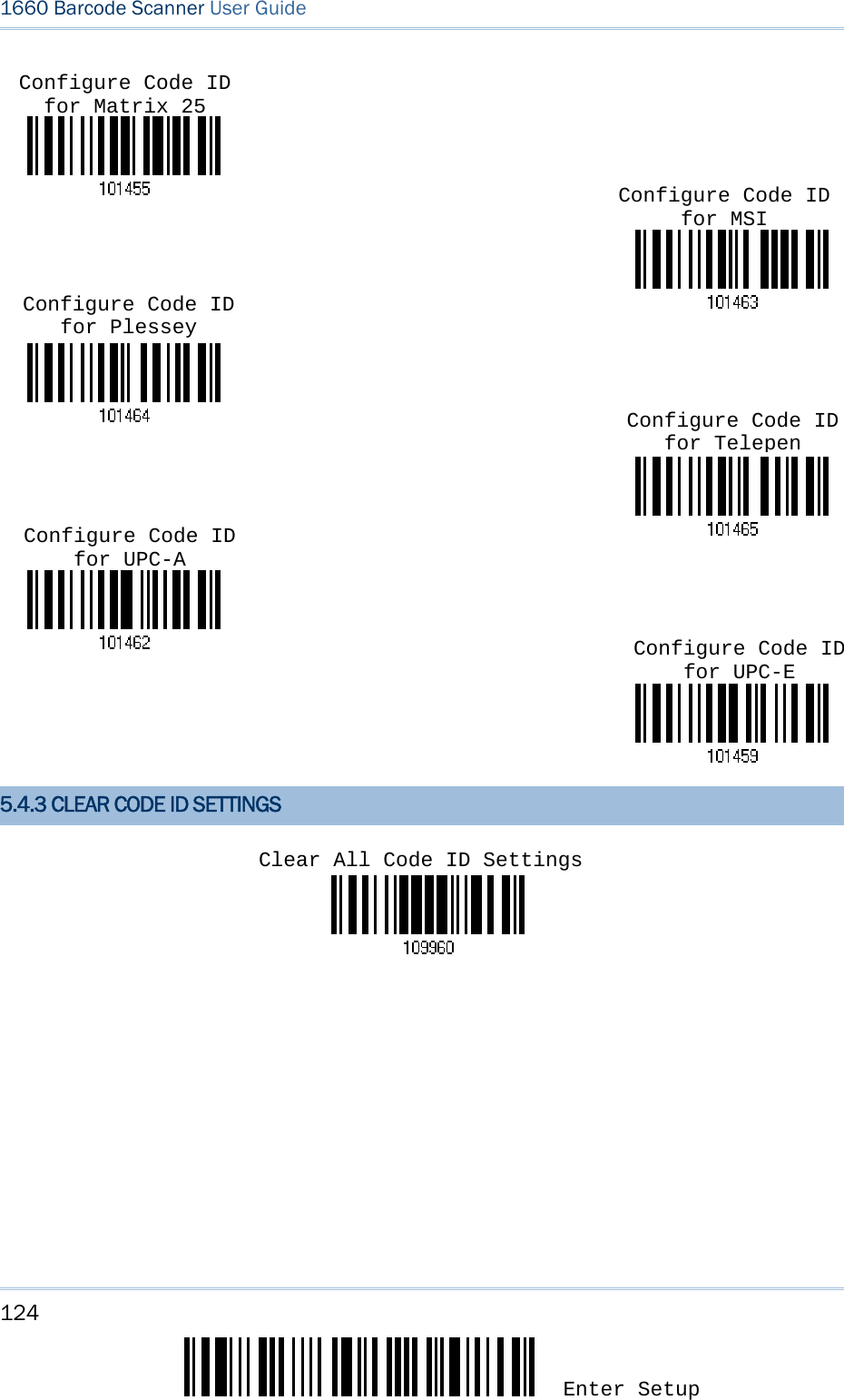
![123 Update Chapter 5 錯誤! 使用 [常用] 索引標籤將 Heading 1 套用到您想要在此處顯示的文字。 Configure Code ID for CodabarConfigure Code ID for Code 39Configure Code ID for Code 93Configure Code ID for Code 128Configure Code ID for EAN-8 Configure Code ID for EAN-13Configure Code ID for French Pharmacode Configure Code ID for Italian PharmacodeConfigure Code ID for Industrial 25 Configure Code ID for Interleaved 25](https://usermanual.wiki/CipherLab/3610/User-Guide-1096354-Page-135.png)
![125 Update Chapter 5 錯誤! 使用 [常用] 索引標籤將 Heading 1 套用到您想要在此處顯示的文字。 5.5 LENGTH CODE A two-digit code representing the length of barcode data (character count) can be inserted in front of data being transmitted. Such "Length" code can be individually enabled or disabled for each symbology. Length Code for Codabar Length Code for Code 39 Length Code for Code 93 Length Code for Code 128 Length Code for GS1-128 (EAN-128) & GS1 DataBar (RSS) Length Code for EAN-8 Apply *Do Not Apply *Do Not Apply Apply Apply Apply Apply *Do Not Apply *Do Not Apply *Do Not Apply *Do Not Apply Apply](https://usermanual.wiki/CipherLab/3610/User-Guide-1096354-Page-137.png)
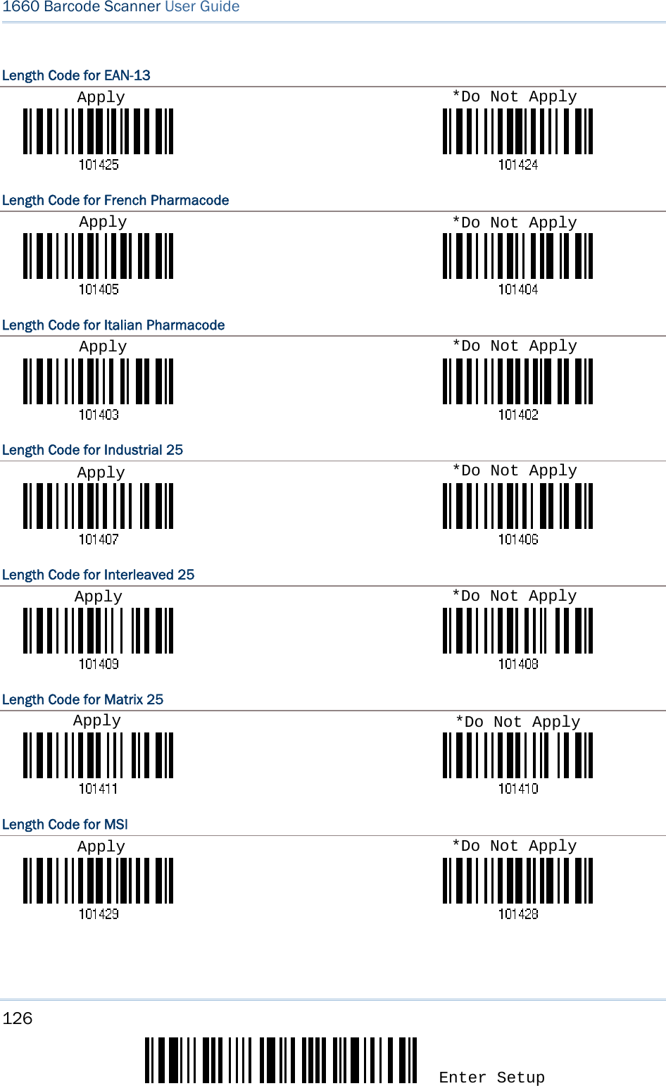
![127 Update Chapter 5 錯誤! 使用 [常用] 索引標籤將 Heading 1 套用到您想要在此處顯示的文字。 Length Code for Plessey Length Code for Telepen Length Code for UPC-A Length Code for UPC-E Apply Apply Apply Apply *Do Not Apply *Do Not Apply *Do Not Apply *Do Not Apply](https://usermanual.wiki/CipherLab/3610/User-Guide-1096354-Page-139.png)
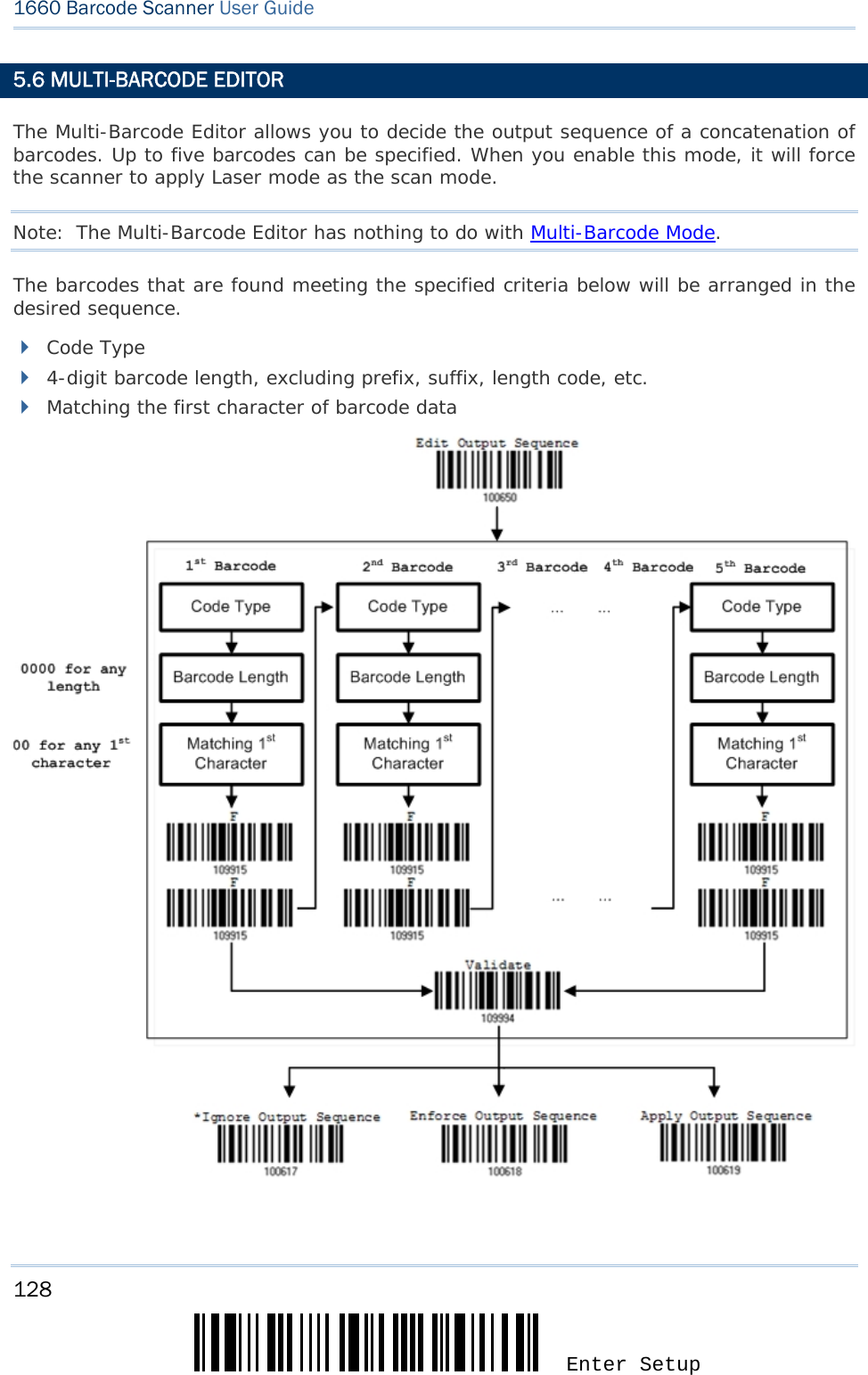
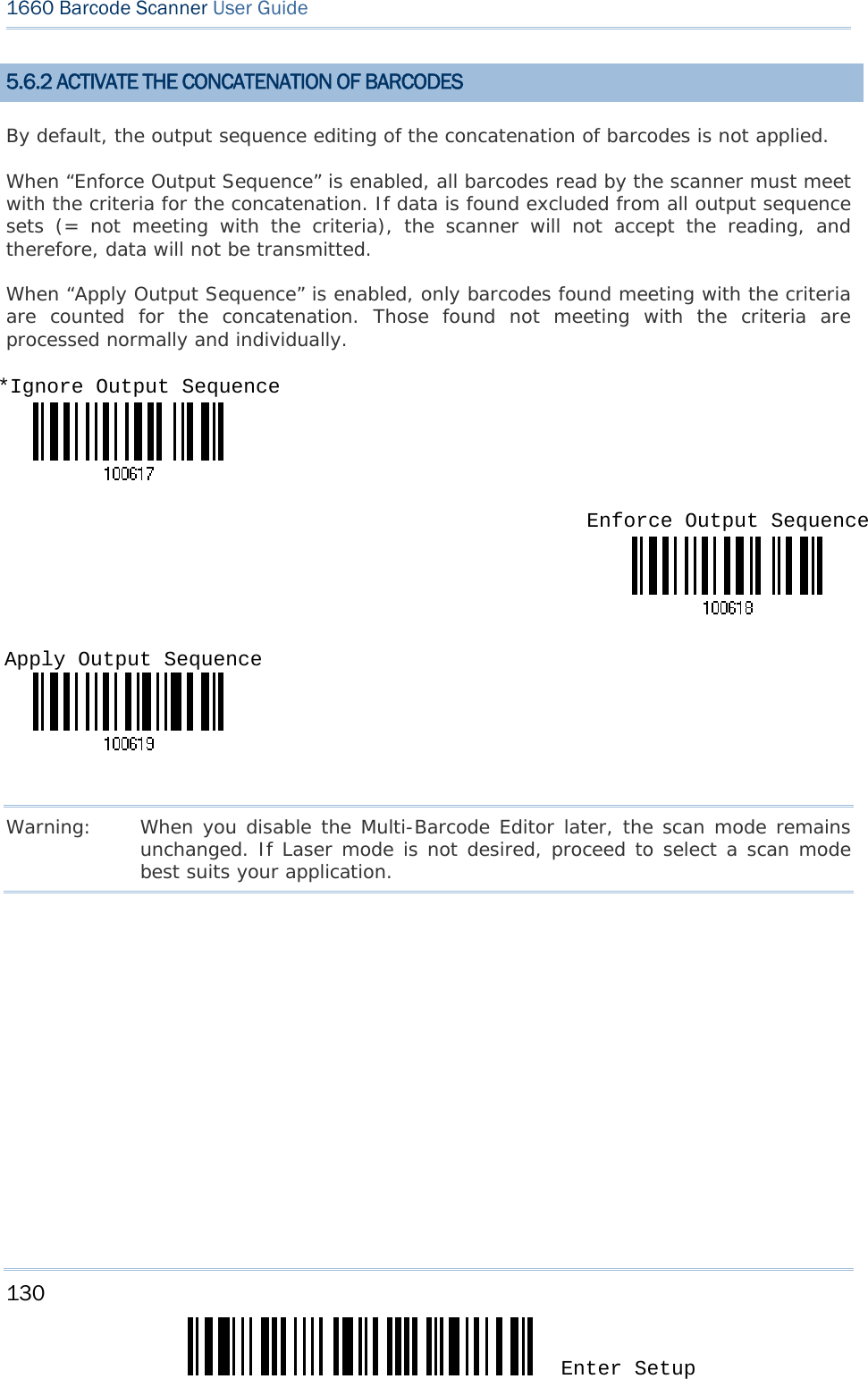
![129 Update Chapter 5 錯誤! 使用 [常用] 索引標籤將 Heading 1 套用到您想要在此處顯示的文字。 5.6.1 EDIT A CONCATENATION OF BARCODES 1) Read the label above to start editing a concatenation of barcodes. 2) Code Type setting – read the “Hexadecimal Value” label on page 170 for Code Type of the (first) barcode. For example, read “4” and “1” for Code 39. Code Type Symbology Code Type Symbology 41 (A) Code 39 4F (O) EAN-8 with Addon 5 42 (B) Italian Pharmacode 50 (P) EAN-13 43 (C) French Pharmacode) 51 (Q) EAN-13 with Addon 2 44 (D) Industrial 25 52 (R) EAN-13 with Addon 5 45 (E) Interleaved 25 53 (S) MSI 46 (F) Matrix 25 54 (T) Plessey 47 (G) Codabar (NW7) 55 (U) GS1-128 (EAN-128) 48 (H) Code 93 56 (V) UPC-A 49 (I) Code 128 57 (W) UPC-A with Addon 2 4A (J) UPC-E0 / UPC-E1 58 (X) UPC-A with Addon 5 4B (K) UPC-E with Addon 2 4C (L) UPC-E with Addon 5 5A (Z) Telepen 4D (M) EAN-8 5B ( [ ) GS1 DataBar (RSS) 4E (N) EAN-8 with Addon 2 3) Barcode Length setting – read the “Decimal Value” label on page 169 for the 4-digit length of the (first) barcode. For example, read “0065” for barcode length of 65 characters or read “0000” for any length. Note: If not reading 0000 for any length, the 4-digit length must exclude prefix, suffix (0x0d by default), length code, etc. 4) Matching Character setting – read the “Hexadecimal Value” label on page 170 for the 1st character that must be found matching in the (first) barcode. For example, read “4” and “1” for matching character “A” as the first character in the barcode or read “00” for any character. 5) Read twice the “F” label on page 170 (“FF”) to complete the setting of each barcode. 6) Read the “Validate” label to end the editing of the barcode set. Edit Output Sequence](https://usermanual.wiki/CipherLab/3610/User-Guide-1096354-Page-141.png)
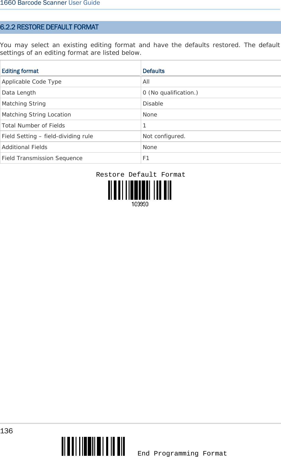
![131 Update The scanner allows advanced data editing by applying user-configured editing formats. The whole processed data can be divided into fields by user-specified rules. These fields together with the user-configurable additional fields consist of the data actually sent to the host computer. [Prefix Code] [Code ID] [Length Code] [Data] [Suffix Code] Additional Field(s) None by default None by default None by default Barcode itself 0x0d by default IN THIS CHAPTER 6.1 Format Selection ...................................................... 132 6.2 Editing Format .......................................................... 134 6.3 Programming Examples ............................................. 150 Chapter 6 APPLYING FORMATS FOR DATA EDITING](https://usermanual.wiki/CipherLab/3610/User-Guide-1096354-Page-143.png)
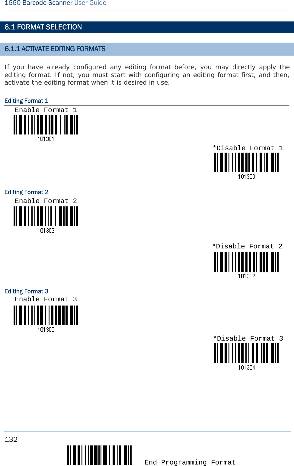
![133 Update Chapter 6 錯誤! 使用 [常用] 索引標籤將 Heading 1 套用到您想要在此處顯示的文字。 Editing Format 4 Editing Format 5 6.1.2 EXCLUSIVE DATA EDITING By default, only barcodes found meeting with the criteria are processed by the editing formats. Those found not meeting with the criteria are processed normally. When “Exclusive Data Editing” is enabled, all barcodes read by the scanner must be processed by the editing formats. If data is found excluded from all enabled editing formats (= not meeting with the specified criteria), the scanner will not accept the reading, and therefore, data will not be transmitted. Yes *No *Disable Format 4Enable Format 4 *Disable Format 5 Enable Format 5](https://usermanual.wiki/CipherLab/3610/User-Guide-1096354-Page-145.png)
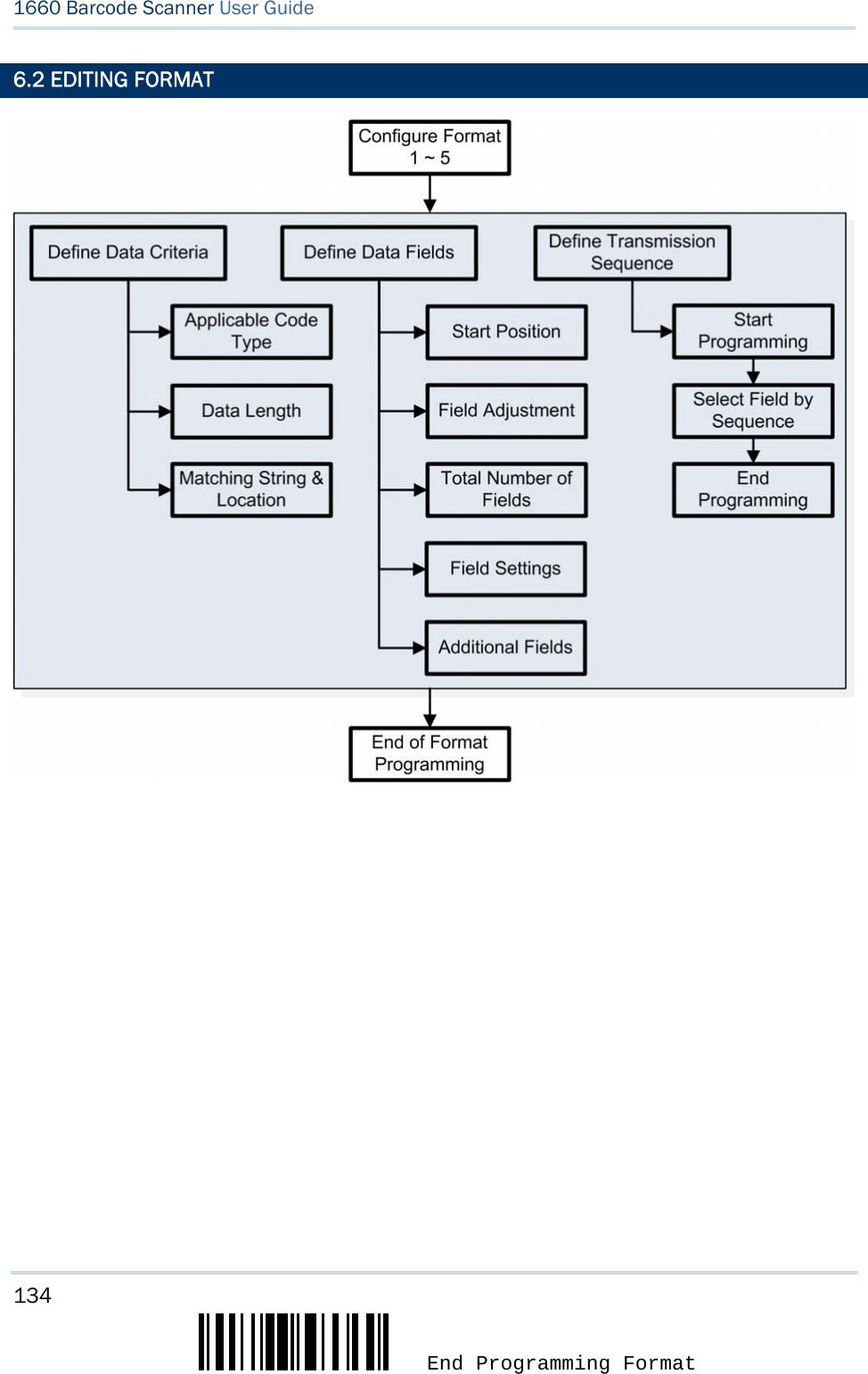
![135 Update Chapter 6 錯誤! 使用 [常用] 索引標籤將 Heading 1 套用到您想要在此處顯示的文字。 6.2.1 SELECT FORMAT TO CONFIGURE Start Programming Format Select one editing format (Format 1~5) and the parameters pertaining to the editing format can then be configured – applicable code type, data length, matching string & location, total number of fields, field settings (field-dividing rule), additional fields, and field transmission sequence. Up to five different formats can be specified. Note: Before you complete the programming of an editing format, if you have the scanner read any label for parameters other than those pertaining to the editing format, it will automatically abort the programming process. End Programming Format After having configured all the desired parameters, you must have the scanner read the “End Programming Format” label, which can be located at the bottom of every even page in this chapter. End Programming Format Configure Format 1 Configure Format 3 Configure Format 4 Configure Format 5 Configure Format 2](https://usermanual.wiki/CipherLab/3610/User-Guide-1096354-Page-147.png)
![137 Update Chapter 6 錯誤! 使用 [常用] 索引標籤將 Heading 1 套用到您想要在此處顯示的文字。 6.2.3 DEFINE DATA CRITERIA Three applicable conditions can be configured to check whether the data read by the scanner can be processed by the particular editing format. Note: Data editing cannot be performed unless the three conditions are all met. Applicable Code Type By default, barcodes of all the supported symbologies will be processed by any editing format, if having been configured and enabled. *Apply to All Codabar Code 39 Code 93 Code 128 EAN-8 EAN-8 Addon 2 EAN-8 Addon 5 EAN-13 EAN-13 Addon 2 EAN-13 Addon 5Clear All](https://usermanual.wiki/CipherLab/3610/User-Guide-1096354-Page-149.png)
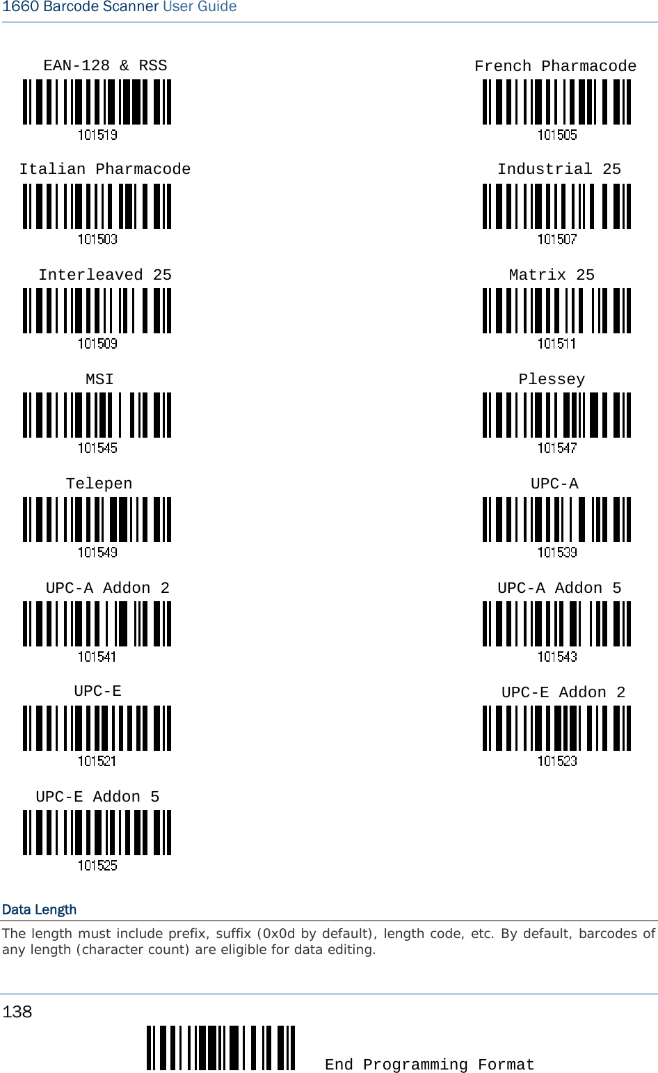
![139 Update Chapter 6 錯誤! 使用 [常用] 索引標籤將 Heading 1 套用到您想要在此處顯示的文字。 You may specify a value from 0 to 254. When zero is given to both, the scanner will not perform the length qualification. 1. Read the label below to specify Max. Length or Min. Length separately, and follow steps 2~3. 2. Read the “Decimal Value” label on page 169 for the desired length. 3. Read the “Validate” label on the same page to complete this setting. Matching String & Location By default, no matching string is specified, and therefore, it is disabled. You may enable this feature by specifying a matching string; up to four characters are allowed. When the Matching String Location is zero, the scanner will only check for the existence of the matching string in the barcode data. You may specify a value from 1 to 254 to indicate where the matching string starts in the barcode data. 1. Read the label to specify a matching string. 2. Read the “Hexadecimal Value” label on page 170 for the desired character string. 3. Read the “Validate” label to complete this setting. 4. Read the label to specify the location of the matching string. 5. Read the “Decimal Value” label on page 169 for the desired location. 6. Read the “Validate” label on the same page to complete this setting. Max. Length Min. Length Matching String…Location of Matching String …](https://usermanual.wiki/CipherLab/3610/User-Guide-1096354-Page-151.png)
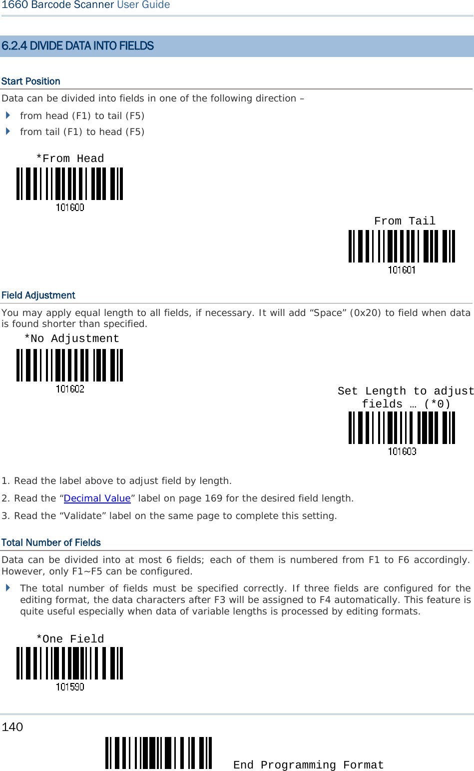
![141 Update Chapter 6 錯誤! 使用 [常用] 索引標籤將 Heading 1 套用到您想要在此處顯示的文字。 Note: The number of configurable fields is always one less than the total number of fields specified. The extra data characters beyond the last field configured will be automatically assigned to the next field. Two Fields Three Fields Four Fields Five Fields Six Fields](https://usermanual.wiki/CipherLab/3610/User-Guide-1096354-Page-153.png)
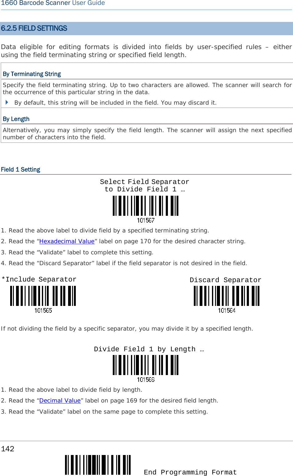
![143 Update Chapter 6 錯誤! 使用 [常用] 索引標籤將 Heading 1 套用到您想要在此處顯示的文字。 Field 2 Setting 1. Read the above label to divide field by a specified terminating string. 2. Read the “Hexadecimal Value” label on page 170 for the desired character string. 3. Read the “Validate” label to complete this setting. 4. Read the “Discard Separator” label if the field separator is not desired in the field. If not dividing the field by a specific separator, you may divide it by a specified length. 1. Read the above label to divide field by length. 2. Read the “Decimal Value” label on page 169 for the desired field length. 3. Read the “Validate” label on the same page to complete this setting. Select Field Separator to Divide Field 2 … *Include Separator Discard Separator Divide Field 2 by Length …](https://usermanual.wiki/CipherLab/3610/User-Guide-1096354-Page-155.png)
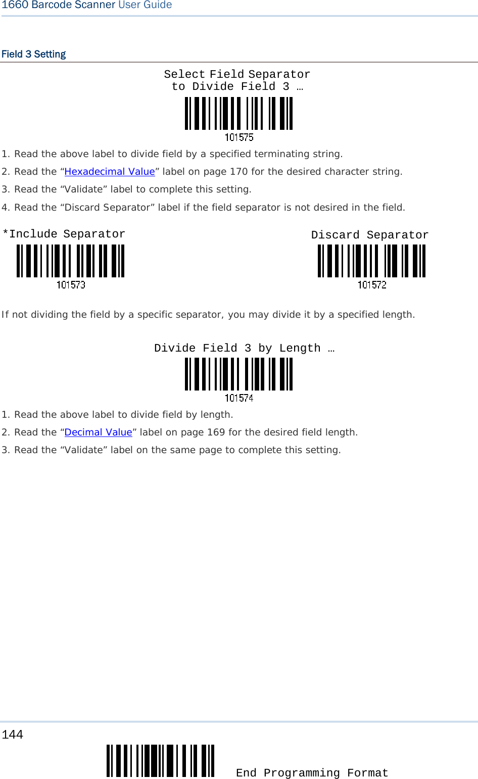
![145 Update Chapter 6 錯誤! 使用 [常用] 索引標籤將 Heading 1 套用到您想要在此處顯示的文字。 Field 4 Setting 1. Read the above label to divide field by a specified terminating string. 2. Read the “Hexadecimal Value” label on page 170 for the desired character string. 3. Read the “Validate” label to complete this setting. 4. Read the “Discard Separator” label if the field separator is not desired in the field. If not dividing the field by a specific separator, you may divide it by a specified length. 1. Read the above label to divide field by length. 2. Read the “Decimal Value” label on page 169 for the desired field length. 3. Read the “Validate” label on the same page to complete this setting. Select Field Separator to Divide Field 4 … *Include Separator Discard Separator Divide Field 4 by Length …](https://usermanual.wiki/CipherLab/3610/User-Guide-1096354-Page-157.png)
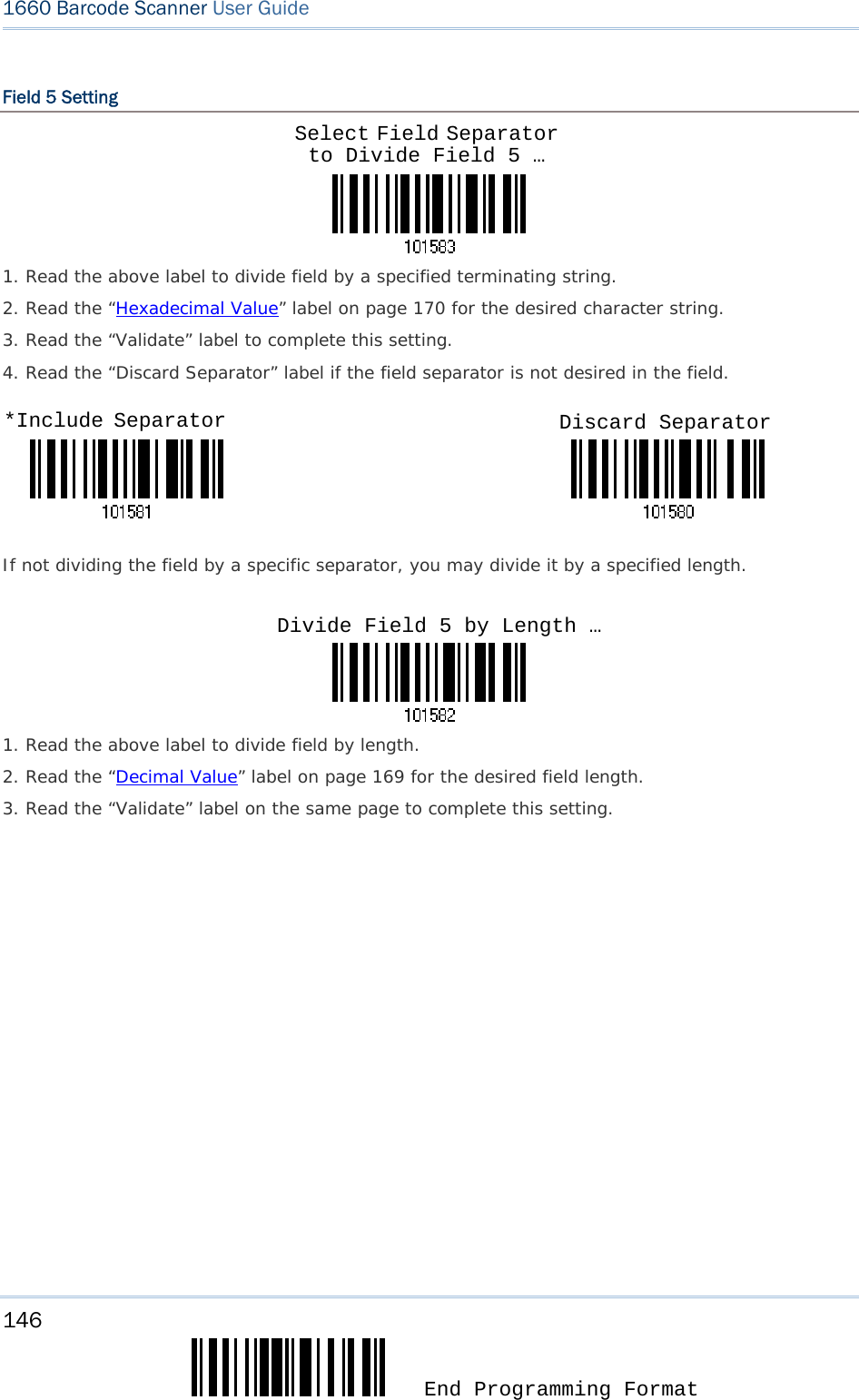
![147 Update Chapter 6 錯誤! 使用 [常用] 索引標籤將 Heading 1 套用到您想要在此處顯示的文字。 Additional Fields Up to five additional fields can be created for each editing format; each of them is numbered from AF1 to AF5 accordingly. 1. Read the label below to specify an additional field, one at a time. 2. Read the “Hexadecimal Value” label on page 170 for the desired additional field. 3. Read the “Validate” label to complete this setting. If “BT HID” or “USB HID” is configured for interface, Key Type and Key Status will then become applicable. You may decide whether or not to apply Key Status when “Normal Key” is selected for Key Type. Refer to Keyboard Wedge Table. Key Type Key Status Scan Code Up to 2 scan code values are allowed. N/A Normal Key Up to 4 character strings are allowed. Default setting Add Shift Add Left Ctrl Add Left Alt Add Right Ctrl Add Right Alt Add Break For example, read labels for [Add Shift], [A], [Add Shift], and [B]. Additional Field 1 … Additional Field 2 …Additional Field 4 …Additional Field 5 … Additional Field 3 …](https://usermanual.wiki/CipherLab/3610/User-Guide-1096354-Page-159.png)

![149 Update Chapter 6 錯誤! 使用 [常用] 索引標籤將 Heading 1 套用到您想要在此處顯示的文字。 3) Read the “End” label to complete this setting. End](https://usermanual.wiki/CipherLab/3610/User-Guide-1096354-Page-161.png)
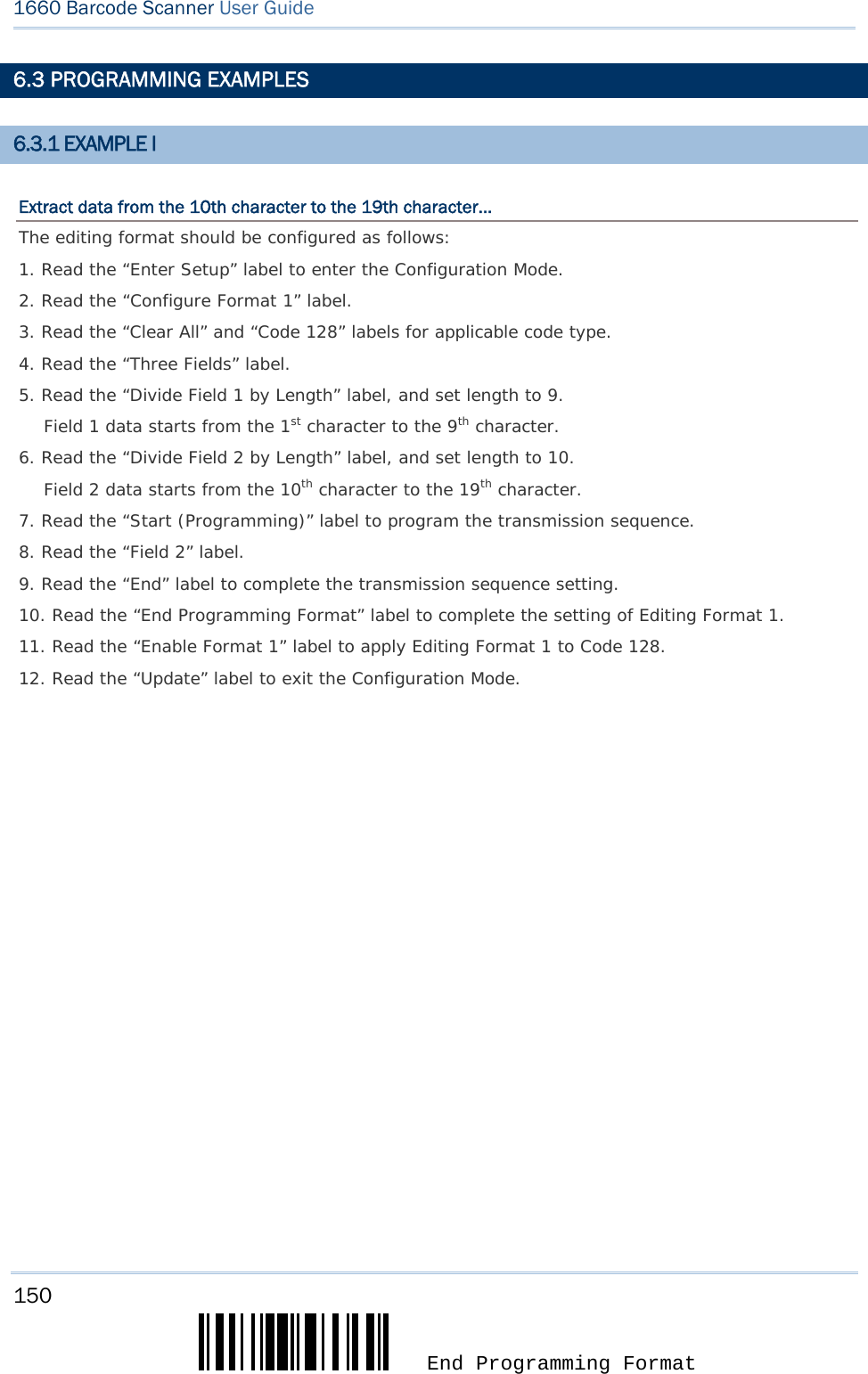
![151 Update Chapter 6 錯誤! 使用 [常用] 索引標籤將 Heading 1 套用到您想要在此處顯示的文字。 5.3.2 EXAMPLE II Extract the date code, item number, and quantity information from barcodes. Data in a barcode is encoded like this: From the 1st character to the 6th character is the date code. From the 7th character to the dash ‘-’ character is the item number. After the dash ‘-’ character is the quantity information. Data will be transmitted like this: The item number goes first, then a TAB character, followed by the date code, then another TAB character, and finally the quantity information. The editing format should be configured as follows: 1. Read the “Enter Setup” label to enter the Configuration Mode. 2. Read the “Configure Format 2” label. 3. Read the “Three Fields” label. 4. Read the “Divide Field 1 by Length” label, and set length to 6. Field 1 data starts from the 1st character to the 6th character. 5. Read the “Select Field Separator to Divide Field 2” label, and use a dash ‘-’ character. Field 2 data starts from the 7th character until the dash ‘-’ character is met. 6. Read the “Additional Field 1” label, and use a tab character for the field. 7. Read the “Start (Programming)” label to program the transmission sequence. 8. Read the “Field 2”, “Additional Field 1”, “Field 1”, “Additional Field 1”, “Field 3” labels. 9. Read the “End” label to complete the transmission sequence (F2 A1 F1 A1 F3) setting. 10. Read the “End Programming Format” label to complete the setting of Editing Format 1. 11. Read the “Enable Format 2” label to apply Editing Format 2 to all code types. 12. Read the “Update” label to exit the Configuration Mode.](https://usermanual.wiki/CipherLab/3610/User-Guide-1096354-Page-163.png)
![153 Update Optical Characteristics 1660 Scan Engine Non-contact type Optical Sensor CCD, 2500 pixels Light Source Visible red LED Wavelength 625 nm RF Characteristics WPAN Module Wireless PAN BT Class 3 compliance Coverage (line-of-sight) Up to 10 meters Profiles Supported Serial Port Profile (SPP), Human Interface Device Profile (HID) Physical Characteristics Memory 1 KB for transmit buffer 256 KB flash for memory mode Switch Push-button switch for [Trigger] key, plus [Power/Delete] key Dimensions 95 mm (L) 35 mm (W) 20 mm (H) Weight Approx. 50 g Color Dark grey SPECIFICATIONS](https://usermanual.wiki/CipherLab/3610/User-Guide-1096354-Page-165.png)
![157 Update Appendix I 錯誤! 使用 [常用] 索引標籤將 Heading 1 套用到您想要在此處顯示的文字。USING A GENERIC DONGLE 1) Refer to 3.2.3 Connect to Dongle for the target scanner to accept the connection request from your computer. 2) Read the following labels in sequence to configure the scanner to use BT SPP as output interface. 3) Read the following labels in sequence for the scanner to enter the download mode. The scanner will respond with beeps to indicate it is ready for downloading. 4) Run the download utility “ProLoad.exe” or “Download.exe” on your computer. (Download.exe requires version 2.3 or later!) Open the firmware update “*.shx”, and select the correct COM port. 5) The scanner will automatically restart itself when upgrading firmware is completed successfully. Enter SetupActivate BT SPP (and read labels for PIN code …)UpdateEnter SetupDownload](https://usermanual.wiki/CipherLab/3610/User-Guide-1096354-Page-169.png)
![159 Update Appendix I 錯誤! 使用 [常用] 索引標籤將 Heading 1 套用到您想要在此處顯示的文字。5) Run the download utility “ProLoad.exe” or “Download.exe” on your computer. (Download.exe requires version 2.3 or later!) Open the firmware update “3610*.shx”, and select the correct COM port. 6) The 3610 will automatically restart itself when upgrading firmware is completed successfully. 7) Read the “Update” label for the scanner to resume its operation (exit the configuration mode). Update](https://usermanual.wiki/CipherLab/3610/User-Guide-1096354-Page-171.png)

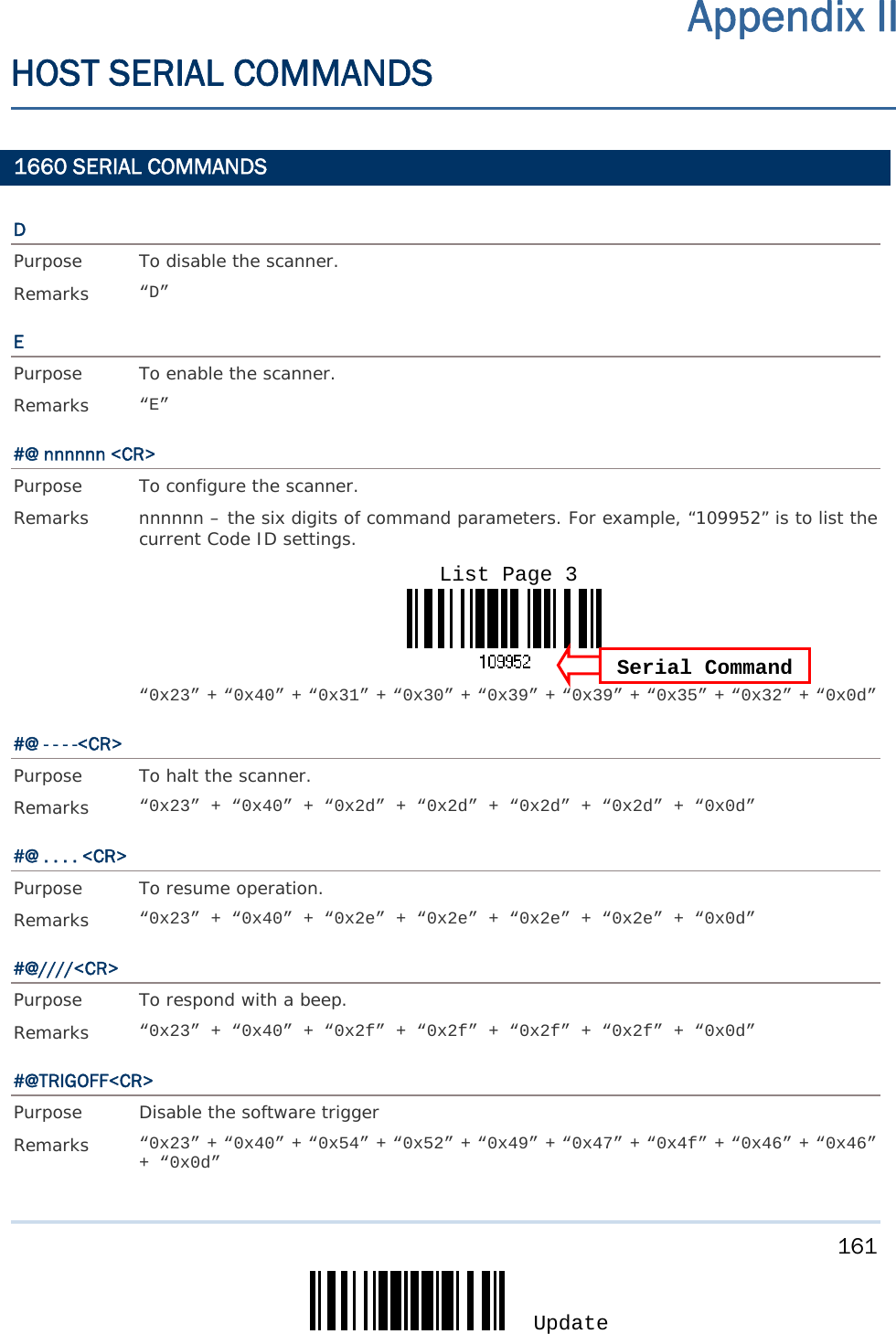
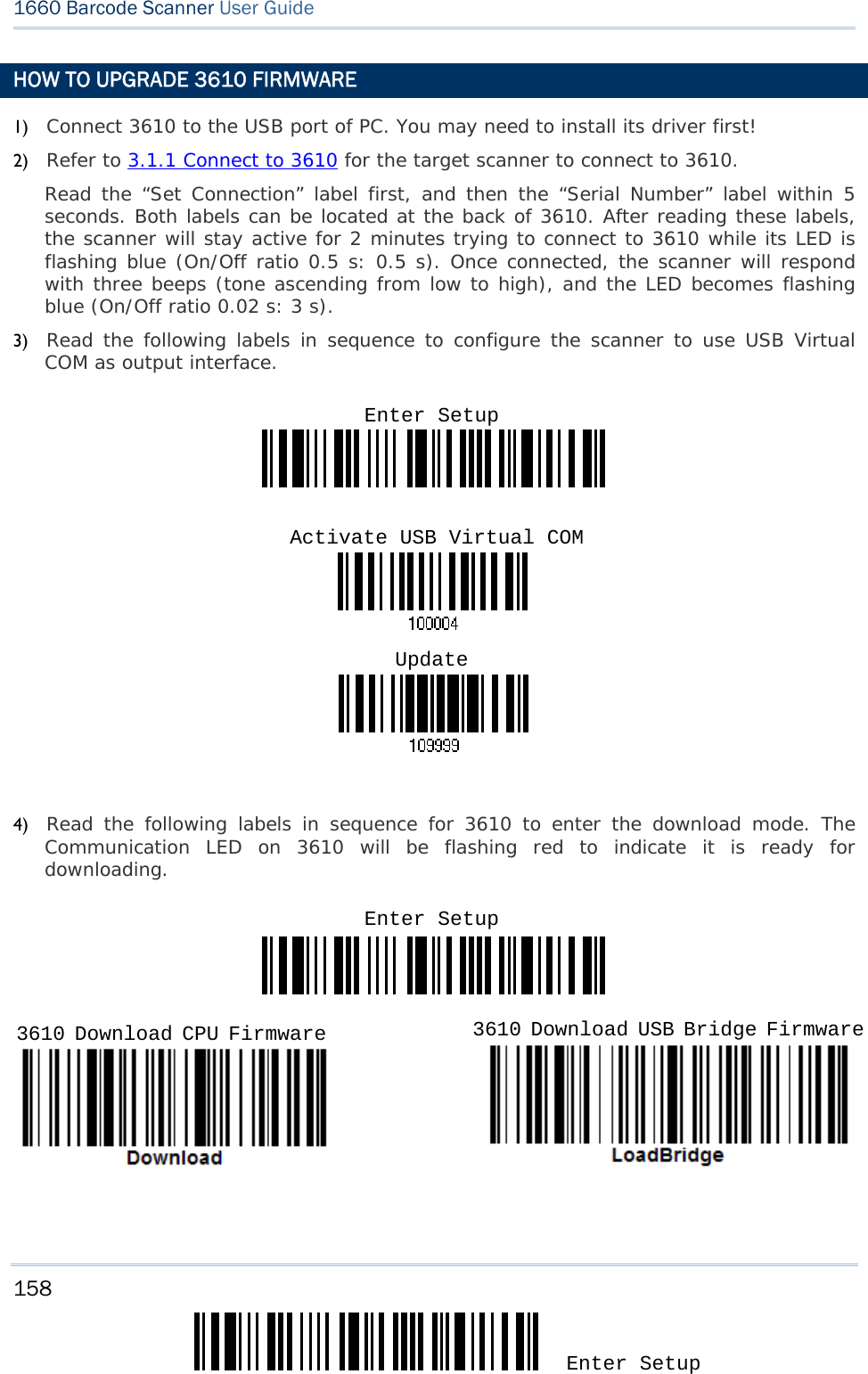
![163 Update Appendix II 錯誤! 使用 [常用] 索引標籤將 Heading 1 套用到您想要在此處顯示的文字。 3610 SERIAL COMMANDS Normally, you can configure the 3610 dongle by having a connected scanner read 3610-related setup labels. 1) Connect 3610 to the USB port of PC. You may need to install its driver first! 2) Refer to 3.1.1 Connect to 3610 for the target scanner to connect to 3610. Read the “Set Connection” label first, and then the “Serial Number” label within 5 seconds. Both labels can be located at the back of 3610. After reading these labels, the scanner will stay active for 2 minutes trying to connect to 3610 while its LED is flashing blue (On/Off ratio 0.5 s: 0.5 s). Once connected, the scanner will respond with three beeps (tone ascending from low to high), and the LED becomes flashing blue (On/Off ratio 0.02 s: 3 s). 3) Read the following labels in sequence to configure 3610. For 3610-related setup labels, refer to the Serial Command table below. Note that for the “Version” and “GetID” labels, you must run HyperTerminal.exe or any text editor to receive the information. If the output interface is USB Virtual COM, run HyperTerminal.exe on your computer to receive the information. If the output interface is USB HID, run any text editor to receive the information. Enter Setup(3610-related setup labels)Update](https://usermanual.wiki/CipherLab/3610/User-Guide-1096354-Page-175.png)
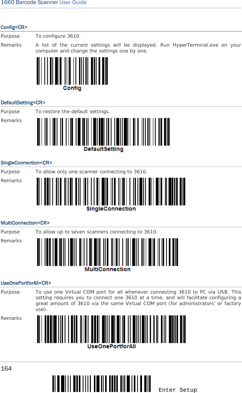
![165 Update Appendix II 錯誤! 使用 [常用] 索引標籤將 Heading 1 套用到您想要在此處顯示的文字。 UseVariablePort<CR> Purpose To use variable Virtual COM port when connecting more than one 3610 to PC via USB. Remarks Version<CR> Purpose To get the firmware versions (CPU+USB Bridge). Remarks GetID<CR> Purpose To get MAC ID. Remarks Download<CR> Purpose To download CPU firmware to 3610. Remarks LoadBridge<CR> Purpose To download USB Bridge firmware to 3610. Remarks](https://usermanual.wiki/CipherLab/3610/User-Guide-1096354-Page-177.png)
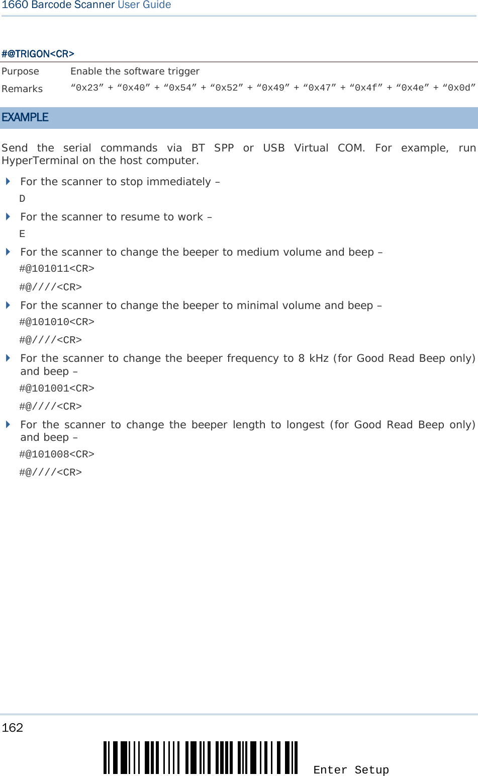
![166 Enter Setup 1660 Barcode Scanner User Guide EXAMPLE Without using the scanner to read the above setup labels for configuring the 3610 dongle, you may run HyperTerminal.exe on the host computer to send serial commands to 3610 via USB Virtual COM or HID. 1) Connect 3610 to the USB port of PC. 2) The Communication LED will indicate when 3610 can accept serial commands after initializing. Refer to the table below. Communication LED Meaning --- Blue, solid Initialize Red, solid Blue, solid Serial command mode with USB Virtual COM: wait 3 seconds for starting a serial command Red, flashing Blue, solid Serial command mode with USB HID: wait 3 seconds for pressing [NumLock] or [CapsLock] 5 times via keyboard If the output interface is USB Virtual COM, run HyperTerminal.exe on your computer. While the Communication LED on 3610 is purple (red and blue both come on), type the serial command within 3 seconds. If the output interface is USB HID, press the “NumLock” or “CapsLoack” key via the keyboard 5 times within 3 seconds while the Communication LED on 3610 is solid blue with red flashing. This will change the interface from USB HID to USB Virtual COM and the Communication LED will become purple (red and blue both come on). Then, run HyperTerminal.exe on your computer. While the Communication LED on 3610 is purple, type the serial command within 3 seconds. After configuring via serial commands, the interface will be reset to USB HID after re-connecting 3610.](https://usermanual.wiki/CipherLab/3610/User-Guide-1096354-Page-178.png)
![167 Update 0 1 2 3 4 5 6 7 8 0 F2 SP 0 @ P ` p 1 INS F3 ! 1 A Q a q 2 DLT F4 " 2 B R b r 3 Home F5 # 3 C S c s 4 End F6 $ 4 D T d t 5 Up F7 % 5 E U e u 6 Down F8 & 6 F V f v 7 Left F9 ' 7 G W g w 8 BS F10 ( 8 H X h x 9 HT F11 ) 9 I Y i y A LF F12 * : J Z j z B Right ESC + ; K [ k { C PgUp Exec , < L \ l | D CR CR* - = M ] m } E PgDn . > N ^ n ~ F F1 / ? O _ o Dly ENTER* Note: (1) ~: Digits of numeric keypad. (2) CR*/Send/ENTER*: ENTER key on the numeric keypad. KEY TYPE If “BT HID” or “USB HID” is configured for interface, Key Type and Key Status will then become applicable. Appendix III KEYBOARD WEDGE TABLE *Normal](https://usermanual.wiki/CipherLab/3610/User-Guide-1096354-Page-179.png)
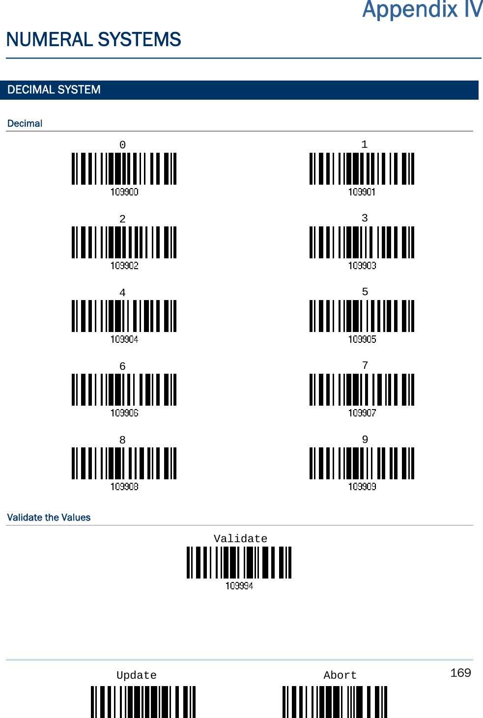
![171 Appendix IV 錯誤! 使用 [常用] 索引標籤將 Heading 1 套用到您想要在此處顯示的文字。 Update AbortValidate the Values ASCII TABLE 0 1 2 3 4 5 6 7 0 DLE SP 0 @ P ` p 1 SOH DC1 ! 1 A Q a q 2 STX DC2 " 2 B R b r 3 ETX DC3 # 3 C S c s 4 EOT DC4 $ 4 D T d t 5 ENQ NAK % 5 E U e u 6 ACK SYN & 6 F V f v 7 BEL ETB ' 7 G W g w 8 BS CAN ( 8 H X h x 9 HT EM ) 9 I Y i y A LF SUB * : J Z j z B VT ESC + ; K [ k { C FF FS , < L \ l | D CR GS - = M ] m } E SO RS . > N ^ n ~ F SI US / ? O _ o DEL Validate](https://usermanual.wiki/CipherLab/3610/User-Guide-1096354-Page-183.png)