CipherLab 85001 Wireless Terminal User Manual Industrial CPT 8500
CipherLab Co., Ltd. Wireless Terminal Industrial CPT 8500
Users Manual
Printed on 28 July, 2005
Reference Manual
8500
Version 0.69
II
Copyright © 2005 Syntech Information Company Limited.
All rights reserved
The software contains proprietary information of Syntech Information Company; it is provided under a
license agreement containing restrictions on use and disclosure and is also protected by copyright law.
Reverse engineering of the software is prohibited.
Due to continued product development this information may change without notice. The information and
intellectual property contained herein is confidential between Syntech Information and the client and
remains the exclusive property of Syntech Information. If you find any problems in the documentation,
please report them to us in writing. Syntech Information does not warrant that this document is error-free.
No part of this publication may be reproduced, stored in a retrieval system, or transmitted in any form or by
any means, electronic, mechanical, photocopying, recording or otherwise without the prior written
permission of Syntech Information.
For product consultancy and technical support, please contact your local sales representative. Also, you may
visit our web site for more information.
The CipherLab logo is a registered trademark of Syntech Information Co., Ltd.
Syntech Information Co., Ltd.
Website: http://www.cipherlab.com
Copyright Notice
III
FCC & Canada Regulations:
zThis device complies with part 15 of the FCC Rules. Operation is subject to the following two
conditions: (1) This device may not cause harmful interference, and (2) this device must accept
any interference received, including interference that may cause undesired operation.
zThis device has been tested and found to comply with the limits for a Class B digital device,
pursuant to Part 15 of the FCC Rules. These limits are designed to provide reasonable protection
against harmful interference in a residential installation. This equipment generates, uses and can
radiated radio frequency energy and, if not installed and used in accordance with the instructions,
may cause harmful interference to radio communications. However, there is no guarantee that
interference will not occur in a particular installation If this equipment does cause harmful
interference to radio or television reception, which can be determined by turning the equipment
off and on, the user is encouraged to try to correct the interference by one or more of the
following measures:
-Reorient or relocate the receiving antenna.
-Increase the separation between the equipment and receiver.
-Connect the equipment into an outlet on a circuit different from that to which the receiver is
connected.
-Consult the dealer or an experienced radio/TV technician for help.
Changes or modifications not expressly approved by the party responsible for compliance could
void the user‘s authority to operate the equipment.
zThis device complies with FCC radiation exposure limits set forth for an uncontrolled
environment. In order to avoid the possibility of exceeding the FCC radio frequency exposure
limits, human proximity to the antenna shall not be less than 20cm (8 inches) during normal
operation.
zThis device can not be worn on the body and at least keep it 20 cm away from body parts other
than hand, wrists, feet and ankles.

IV
This section is specifically prepared for those who are in charge of taking care of the terminal, such as a
terminal operator or maintenance engineer.
Here are some tips on how to take care and maintain the terminal.
Taking care of the terminal
Always keep electric equipments, such as the terminal, away from any flammable sources.
Always make sure there is stable power supply for the terminal or its peripherals to operate properly.
This terminal is intended for industrial use. Although the terminal is rated IP 64, it may do damage to the
terminal when being exposed to extreme temperatures or soaked wet.
When the body of the terminal gets dirty, use a clean and wet cloth to wipe off the dust. DO NOT use/mix
any bleach or cleaner. Always keep the LCD dry.
For a liquid crystal display (LCD) or touch screen, DO NOT use any pointed or sharp object to move
against the surface. Use a clean, non-abrasive, lint-free cloth to wipe dust off the screen.
Maintaining the terminal
If you want to put away the terminal for a period of time, download the collected data to a host first, and
then take out the battery pack. Store the terminal and battery pack separately.
When the terminal resumes its work, the main and backup batteries will take a certain time to become
fully charged.
If you shall find the terminal malfunctioning, refer to the Troubleshooting section for self help first.
If the problem persists, write down the specific scenario and consult your local sales representative.
Under no circumstances, internal components are self-serviceable.
Care & Maintenance
V
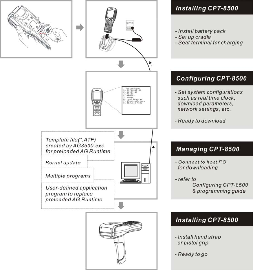
Below illustrates how to have the terminal ready to work. This scenario makes use of a cradle, which may be
replaced by a gang charger and other interface to PC.
Figure 1: Have CPT-8500 ready
Getting Started

i
Contents
Copyright Notice II
FCC Regulations III
Compliance with Standards III
Care & Maintenance IV
Getting Started V
Preface 1
Typographical Conventions..........................................................................................................................2
Revision History ...........................................................................................................................................2
CHAPTER 1: Introducing CPT-8500 3
1.1 Product Highlights ..................................................................................................................................3
1.2 Nomenclature..........................................................................................................................................4
1.2.1 CPT-8500 .................................................................................................................................4
1.2.2 Accessories & Peripherals ........................................................................................................5
1.2.3 Dimensions ...............................................................................................................................6
1.3 Features...................................................................................................................................................7
1.3.1 Power........................................................................................................................................7
1.3.2 CPU ..........................................................................................................................................8
1.3.3 Memory & Calendar.................................................................................................................8
1.3.4 Keyboard ..................................................................................................................................9
1.3.5 LCD........................................................................................................................................12
1.3.6 Status LED..............................................................................................................................13
1.3.7 Buzzer.....................................................................................................................................13
1.3.8 Vibrator ..................................................................................................................................13
1.3.9 Readers ...................................................................................................................................14
1.3.10 Wireless Support...................................................................................................................15
1.3.11 Resistance .............................................................................................................................20
1.3.12 Terminal Emulation..............................................................................................................20
1.3.13 Programming Support...........................................................................................................20

ii Contents
1.4 Unpacking the package.........................................................................................................................21
1.5 Options..................................................................................................................................................21
CHAPTER 2: Installing CPT-8500 22
2.1 Battery Pack..........................................................................................................................................23
2.2 Hand Strap ............................................................................................................................................24
2.3 Pistol Grip.............................................................................................................................................25
2.4 Cradle, serial or modem........................................................................................................................26
2.4.1 Cradle Options........................................................................................................................28
2.4.2 Status Indicators .....................................................................................................................29
2.4.3 DIP Switch..............................................................................................................................30
2.5 Charging ...............................................................................................................................................31
2.5.1 Cradle .....................................................................................................................................31
2.5.2 Gang Charger..........................................................................................................................31
2.6 Communications ...................................................................................................................................31
2.6.1 Wired......................................................................................................................................32
2.6.2 Wireless ..................................................................................................................................33
CHAPTER 3: Software Architecture 34
3.1 Program Module ...................................................................................................................................35
3.2 System & Kernel Modules....................................................................................................................36
CHAPTER 4: Configuring CPT-8500 37
4.1 System Menu ........................................................................................................................................38
4.1.1 Information.............................................................................................................................39
4.1.2 Settings ...................................................................................................................................40
4.1.3 Tests........................................................................................................................................45
4.1.4 Memory ..................................................................................................................................47
4.1.5 Power......................................................................................................................................48
4.1.6 Load Program .........................................................................................................................49
4.1.7 Bluetooth Menu ......................................................................................................................50
4.1.8 IEEE 802.11b Menu ...............................................................................................................62
4.2 Program Manager .................................................................................................................................70
4.2.1 Download ...............................................................................................................................71
4.2.2 Activate ..................................................................................................................................73
4.2.3 Upload ....................................................................................................................................74
4.3 Kernel Menu .........................................................................................................................................75
4.3.1 Kernel Information .................................................................................................................76
4.3.2 Load Program .........................................................................................................................77
4.3.3 Kernel Update.........................................................................................................................77
4.3.4 Test & Calibrate .....................................................................................................................78
4.3.5 Bluetooth Menu ......................................................................................................................79

Contents iii
CHAPTER 5: Managing CPT-8500 80
5.1 For proprietary applications..................................................................................................................80
5.2 For custom applications ........................................................................................................................80
Specifications 81
Troubleshooting 83
Appendix I - Download Utilities 86
ProgLoad, all-in-one interface ....................................................................................................................87
IRLoad, Cradle-IR interface .......................................................................................................................89
Download, RS-232 or IrDA interface.........................................................................................................90
TcpLoad, IP interface .................................................................................................................................91
Index 92

iv
Table of Figures
Figure 1: Have CPT-8500 ready ................................................................................................V
Figure 2: Nomenclature (front & back) .....................................................................................4
Figure 3: Nomenclature of accessories.......................................................................................5
Figure 4: Dimensions ...................................................................................................................6
Figure 5: 24-key layout ..............................................................................................................10
Figure 6: 44-key layout ..............................................................................................................11
Figure 7: Coverage of wireless technologies ............................................................................15
Figure 8: Installing battery pack ..............................................................................................24
Figure 9: Installing hand strap .................................................................................................25
Figure 10: Installing pistol grip ................................................................................................26
Figure 11: Setting up cradle......................................................................................................27
Figure 12: Cradle LEDs ............................................................................................................29
Figure 13: Cradle - DIP switch .................................................................................................30
Figure 14: Flow chart of cradle communications....................................................................32
Figure 15: Software Architecture .............................................................................................34
Figure 16: Downloading through Program Manager.............................................................72
Figure 17: Downloading in Kernel mode .................................................................................87
Figure 18: Downloading in Program Manager mode.............................................................87

1
The CPT-8500 Industrial Portable Data Terminal is a robust, versatile, high performance
terminal. It is specifically designed for all-day, everyday use as well as for data-intensive
applications in harsh environments.
This line of product comes with built-in Bluetooth wireless technology and allows for
optional 802.11b and/or GSM/GPRS modules, enabling all the time, anywhere applications
and seamless real time sharing of performance. The terminal is bundled with powerful and
rich features to ensure success in timely processing of information, even in rigorous
industrial environments, and thus, makes an ideal choice for a wireless solution in either
increasing business flexibility or answering the demanding needs of heavy-duty terminals.
Being programmable, this handy terminal can run custom applications or terminal
emulation applications.
This manual serves to guide you through how to install, configure, and operate the terminal.
The Care & Maintenance section is specifically prepared for those who are in charge of
taking care of the terminal.
We recommend you to keep one copy of the manual at hand for quick reference or
maintenance purposes. To avoid any improper disposal or operation, please read the manual
thoroughly before use.
Thank you for choosing the CipherLab products!
In This Chapter
Typographical Conventions............................................... 2
Revision History ................................................................ 2
Preface

2 Industrial CPT-8500 Reference Manual
Typographical Conventions
Before you start using this manual, it is important to understand the terms and typographical
conventions used in the documentation.
The following kinds of formatting in the text identify special information.
Formatting convention Type of Information
Triangular Bullet (¾) Highlight features or subjects that stand out from the
text.
Special Bold Items you must select, such as menu options,
command buttons, or items in a list.
Emphasis Use to emphasize the importance of a point or for
variable expressions such as parameters.
CAPITALS Names of keys on the keyboard. for example, SHIFT,
CTRL, or ALT.
KEY+KEY Key combinations for which the user must press and
hold down one key and then press another, for
example, CTRL+P, or ALT+F4.
Revision History
Version Release Date Notes
0.69 July 28, 2005 Draft for internal reference

3
This chapter mainly explains the hardware parts and features of the CPT-8500 terminal.
In This Chapter
1.1 Product Highlights....................................................... 3
1.2 Nomenclature............................................................... 4
1.3 Features........................................................................ 7
1.4 Unpacking the package................................................ 21
1.5 Options......................................................................... 21
1.1 Product Highlights
Ergonomic design - ruggedized yet streamlined, with hand strap for secure hold.
Built tough to survive harsh environments - splash, dust & drop resistant.
Upgradeable memory - optional memory card provides up to 8 MB for data and
program storage.
Dual mode support - One scan engine (integrated barcode scanner/imager) plus one
RFID reader.
Total wireless solution - connectivity includes IrDA, Bluetooth, 802.11b and
GSM/GPRS.
Large graphic monochrome LCD touch screen supports double-byte characters, user
fonts, and bitmap graphics. The touch screen featuring signature capture is activated
with its stylus or a finger. Software programmable.
Programmable feedback includes buzzer, status light and vibrator.
Quick link to any backend database through VT100/200 and IBM 5250 emulation.
Proprietary programming tool - Windows-based application generator (AG) for easy
customization of preloaded AG application.
Programming support includes BASIC & C compilers.
CHAPTER 1
Introducing CPT-8500
4 Industrial CPT-8500 Reference Manual
1.2 Nomenclature
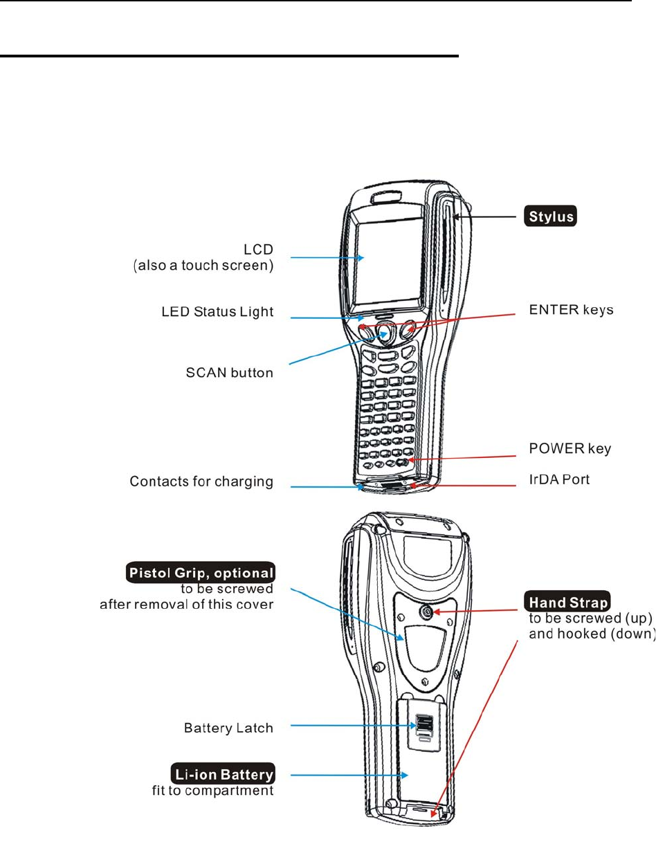
1.2.1 CPT-8500
Figure 2: Nomenclature (front & back)
Chapter 1 Introducing CPT-8500 5
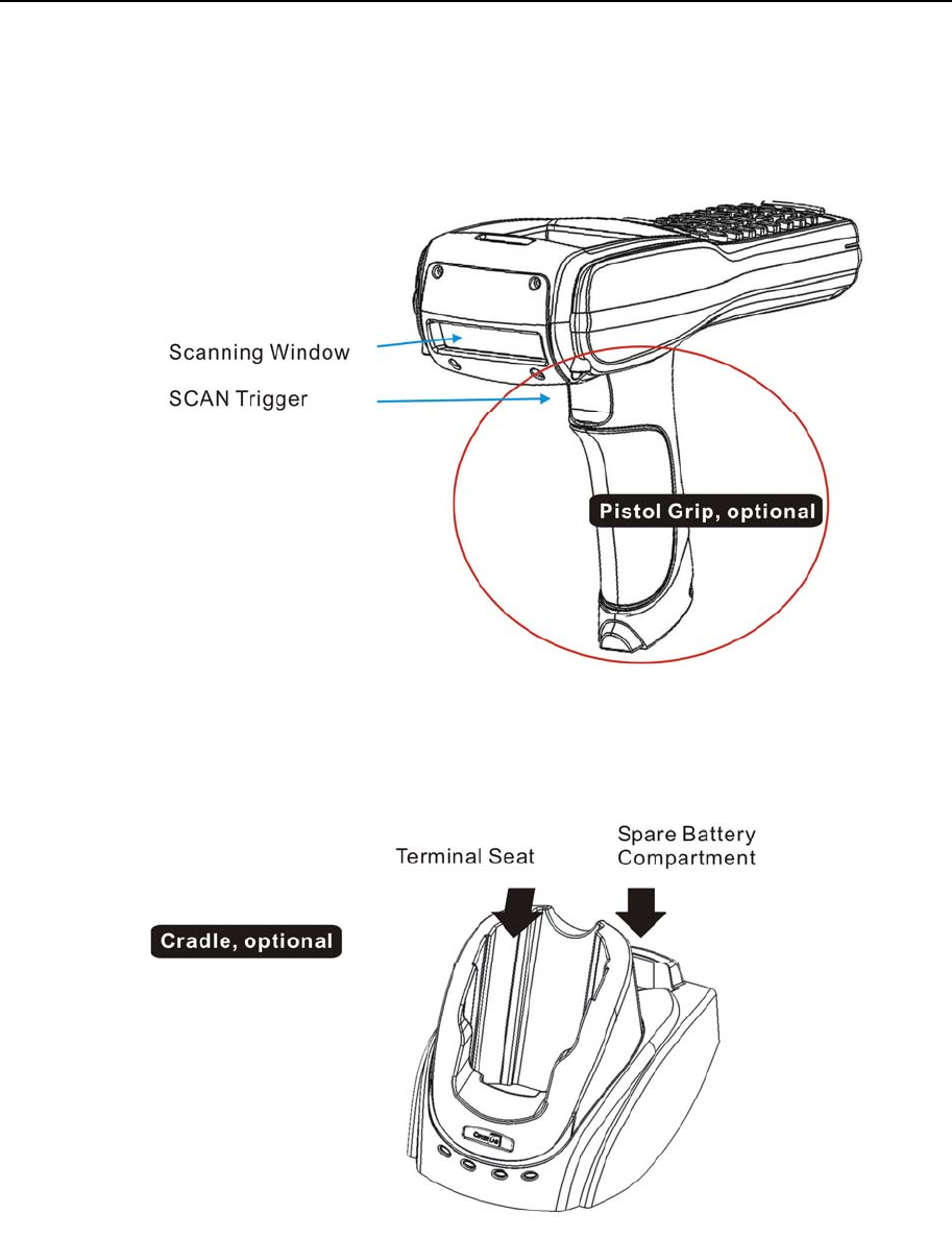
1.2.2 Accessories & Peripherals
Figure 3: Nomenclature of accessories
6 Industrial CPT-8500 Reference Manual
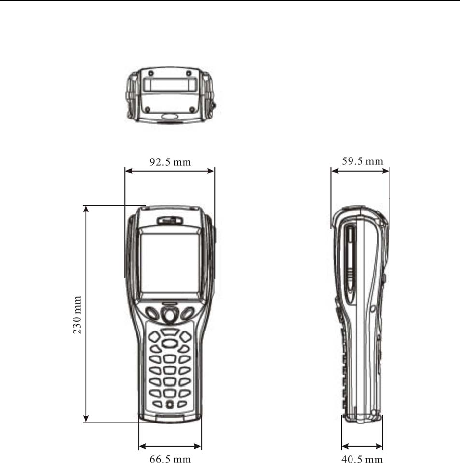
1.2.3 Dimensions
Figure 4: Dimensions

Chapter 1 Introducing CPT-8500 7
1.3 Features
1.3.1 Power
¾ Main Battery
The CPT-8500 is powered by a rechargeable 3.7 V/4000 mAh Li-ion battery pack, and it
takes approximately four hours to fully charge it. During normal operation, the terminal can
work for up to 500 hours.
For power saving purpose, always turn off the backlight while working in a well-lit area.
When the backlight is on for extended periods of time, the main battery will become low
sooner than expected.
The smart battery icon on the LCD screen shows the status of power consumption. There
are two ways to monitor a low battery charge or discharged battery from the screen.
Examine the level of the 4-bar battery icon
Monitor voltage level (see 4.1.5 Power)
¾ Backup Battery
In addition, one 3.0 V/7 mAh rechargeable Lithium button cell on the main board retains
data in SRAM and maintains the running of the real-time clock and calendar. It takes at least
twenty-four hours to fully charge the backup battery.
For a fully charged backup battery, it can last for at least one week. However, it is not
necessary to fully charge the backup battery for the terminal to work.
Monitor voltage level (see 4.1.5 Power)
¾ Initial Charging
The main battery must be fully charged before using the terminal for the first time. Because
the internal backup battery is constantly charged from the main battery, the initial charging
requires installing the battery pack to the terminal and then seating the terminal in the cradle
for charging. This will have main/backup batteries charged at the same time.
Note: For initial charging, we recommend that you install the main battery to the terminal
and seat the terminal in the cradle to charge the main/backup batteries at the same
time. It requires approximately 4 hours fully charging the main battery.

8 Industrial CPT-8500 Reference Manual
¾ Caution of Low Battery Charge
The battery pack is the only power source for the terminal to work. It also charges the
backup battery on the main board so that the data stored in SRAM can be retained properly.
Therefore, when the main battery charge goes low, replace the battery pack with a charged
one or charge it as soon as possible. Always save data before it is too late.
Warning! Data loss may occur with SRAM during low battery condition. Always
save data before running out of power or keep a fresh battery for
replacement.
1.3.2 CPU
A 32-bit low power CMOS CPU is utilized.
1.3.3 Memory & Calendar
The CPT-8500 is a real-time data collection model, that is, the collected data will be sent
back to a host computer immediately during normal operation.
An optional memory card upgrades memory to 4 or 8 megabytes. With upgradeable
memory, the terminal can further accommodate one or more application programs.
Note: When in use, the memory card will override the internal SRAM.
Program Memory
9 2 megabytes flash memory for core, OS, application programs, fonts, etc.
Data Memory
9 2 megabytes SRAM with contents backup by a 7 mAh rechargeable Lithium button cell.
Calendar
9 A calendar chip is equipped for accurate time/date logging.
9 Non-stop operation is also provided through the same Li button cell for SRAM contents backup.

Chapter 1 Introducing CPT-8500 9
¾ Caution of Data Loss
When the main battery is removed or drained, the backup battery on the main board is to
retain the contents of SRAM and maintain the running of the calendar for at least one week,
on condition that the backup battery has already been fully charged.
If the terminal is to be put away for a couple of days, you should be aware that data loss
occurs when both the main and backup batteries discharge completely. Therefore, it is
necessary to save data in a host computer before putting away the terminal.
Note: Being fully charged, the backup battery can last at least 1 week.
1.3.4 Keyboard
The terminal is equipped with a keypad of either 24 keys or 44 keys, which has
programmable LED backlight, for system setup, user entry and so on.
Silicon rubber has been chosen for their durability and prompt feedback. The key click can
be configured through the System Menu.
Note: Functionality of keys is application-dependent.
¾ Screen Icons
The following icons appear on the screen when a certain mode is activated, that is, holding
down the specific key is unnecessary. Simply press another key or red-coded function key
([F1] ~ [F12]) to produce a result.
24-key
A / a:
:
Press [Alpha] to enter the alphabetic mode, capital or small letters.
Press [FN] to enter the function mode (user definable).
44-key
:
:
:
Press [Shift] to enter the special function mode (user definable).
Press [RED] to enter the function mode (user definable).
Press [Alt] to enter the special function mode (user definable).
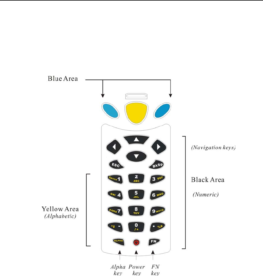
10 Industrial CPT-8500 Reference Manual
24-key layout
The layout of the 24-key keypad is similar to that of a telephone, which consists of an
alphanumeric keypad, numbers and assorted characters.
This keypad is set to numeric mode by default. For alpha mode, simply press [ALPHA] to
toggle between alpha and numeric modes.
Figure 5: 24-key layout
Chapter 1 Introducing CPT-8500 11
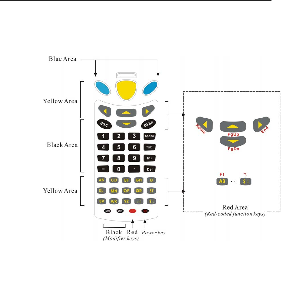
44-key layout
The layout of the 44-key keypad includes numeric, alphabetic, assorted characters, function
and modifier keys.
Figure 6: 44-key layout
For the 44-key keypad, these keys can be categorized into the following groups by color:
Blue Area:
9 Two [Enter] keys: user-friendly and convenient for either right-handed or left-handed operator to
perform general function of a [Enter] key.
9 It can be used together with [RED] modifier key: [Enter] + [RED] = alternately turn ON/OFF the
backlight of LCD and keyboard.

12 Industrial CPT-8500 Reference Manual
Black Area:
9 Power key
9 Numeric keys
9 Modifier keys: [Shift] or [Alt] that modifies its next key. The functionality depends on software
application.
9 Others like [Backspace], [ESC], [Space], [Tab], [Insert], [Delete], [ - ], [ . ]
Yellow Area:
9 [Scan] button
9 Navigation keys for moving the cursor up, down, left, right.
9 Alphabetic keys
9 Others like punctuation keys for comma & semi-colon, dollar & colon.
Red Area:
9 [RED] modifier key: the solid red key next to the Power key
9 [RED] followed by one red-coded key: The [RED] modifier key modifies (activates) the second key.
Its functionality is determined by the red-coded key, which is specified by red letters under the
navigation keys or on top of alpha keys and some punctuation keys.
1.3.5 LCD
The terminal comes with a 3” FSTN graphic LCD, 160 by 160 pixels resolutions, which can
be configured to display text or graphics, such as specific font and company logo, to meet
varying application needs.
English Font:
Small fonts (6×8 pixels)
Large fonts (8×16 pixels)
21 by 8 lines
16 by 4 lines
Chinese Font:
(16×16 pixels) 8 by 4 lines
Other language fonts, company logo…
Programmable

Chapter 1 Introducing CPT-8500 13
¾ Backlight Setting
The LED backlight of screen and keyboard helps ease reading under dim environments. It
can be alternately toggled ON and OFF by simultaneously pressing the following keys:
24-key: [Enter] + [FN]
44-key: [Enter] + [RED]
¾ Touch Screen & Signature Capture
This LCD is also a touch screen, which enables the use of a stylus for handwriting. It also
features signature capture that can save signature as confirmation of receipt when delivering
goods to door.
The screen can be calibrated by tool provided in the System Menu.
Warning! DO NOT use any pointed or sharp objects to move against the surface of
the screen.
1.3.6 Status LED
The dual-color LED on top of the [Scan] button is to provide information on status of
scanning. It is programmable for diagnostics and application dependant.
Red LED - Error
Green LED - Good Read
1.3.7 Buzzer
The buzzer, a low power transducer type, can be programmed for status feedback. Its pitch
and duration are software programmable.
1.3.8 Vibrator
Like a modern mobile phone, the terminal is integrated with a vibrator. It is software
programmable and especially useful when working in a noisy environment.

14 Industrial CPT-8500 Reference Manual
1.3.9 Readers
A wide variety of readers is available for delivering flexibility to meet different
requirements.
Note: All specifications are subject to change without prior notice.
Long Range Imager
Resolution: 0.125 mm ~ 1.00 mm
Depth of field: 2 ~ 20 cm
Width of field: 45 mm ~ 124 mm
Scan rate: 100 scans/sec
Ambient Light Rejection: 1200 lux (Direct Sun-light)
2500 lux (Fluorescent Light)
Laser Scanner
Light source: Visible laser diode operating at 670 ± 15 nm
Depth of field: 5 ~ 95 cm, depends on barcode resolution
Scan angle: 42° nominal
Scan rate: 36 ± 3 scans/sec
Minimum print contrast: 20% absolute dark/light reflectance at 670 nm
2D Scanner
???
???
RFID Reader
13.56 MHz, Philips Mifare: From contact to 6 cm
¾ Dual Mode Support
The terminal allows one integrated scan engine, plus the RFID reader.
Chapter 1 Introducing CPT-8500 15
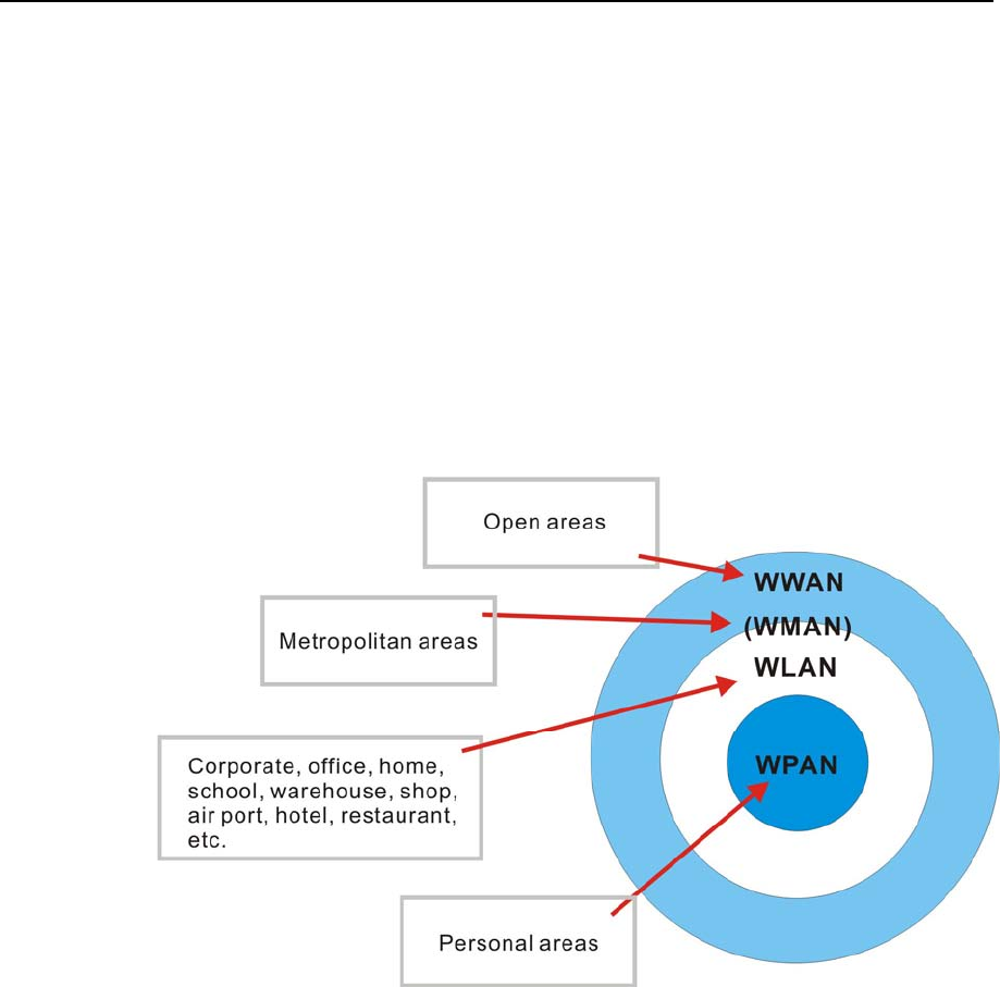
1.3.10 Wireless Support
The CPT-8500 terminal supports state-of-the-art wireless technologies so that it is able to
send/receive data in real time in an efficient way.
WPAN: IrDA, Standard infrared (IR) technology for data exchange, embedded
WPAN: Bluetooth technology for cable replacement & data exchange, embedded
WLAN: IEEE 80.211b for wireless networking, optional module
WWAN: GSM/GPRS for short message service, optional module
Generally, the coverage of each technology can be viewed as follows.
Figure 7: Coverage of wireless technologies

16 Industrial CPT-8500 Reference Manual
Standard IrDA Port
The terminal has an integrated IrDA port at the bottom, which can directly establish
connection with an IrDA device for printing or data exchange. Simply have the IrDA port of
the terminal toward the IrDA port of the target device.
IrDA specifications define communications (transmit/receive data) between two IrDA
enabled devices within a very short range, line-of-sight.
IrDA Specification
Infra red: Optical
Data rate: Up to 115200 bps
Coverage: From contact to at least 30 cm, line-of-sight
Connected devices: Peer-to-Peer
Standard: Version 1.0
Note: All specifications are subject to change without prior notice.

Chapter 1 Introducing CPT-8500 17
Bluetooth Class 2
With built-in Bluetooth technology, the terminal can directly communicate with any
Bluetooth enabled device, not necessarily line-of-sight.
Bluetooth is an industrial standard for Wireless Personal Area Networking (WPAN),
which enables wireless communications within a short range.
Serial Port Profile (SPP) is for ad-hoc networking, without going through any access
point.
Personal Area Networking Profile (PAN) makes use of Bluetooth Network
Encapsulation Protocol (BNEP) for IP networking over Bluetooth. Access points
required.
Dial-Up Networking Profile (DUN) makes use of a Bluetooth modem or mobile phone
as a wireless modem.
Bluetooth Specification
Frequency Range: 2.4 ~ 2.5 GHz
Modulation: FHSS with GFSK
Profiles: SPP, PAN, DUN
Maximum Output Power: 10 mW
Data rate: 721 kbps
Coverage: 50 meters line-of-sight
Connected devices: SPP mode - either Master or Slave
Server-to-Client (access point required)
Standard: Version 1.2
Note: All specifications are subject to change without prior notice.

18 Industrial CPT-8500 Reference Manual
IEEE 802.11b
When the 802.11b module is installed, the terminal can easily connect to legacy networks
through access points (APs). Roaming among different networks is possible.
IEEE 802.11b is an industrial standard for Wireless Local Area Networking (WLAN),
which enables wireless communications over a long distance.
The speed of connection between two wireless devices will vary with range and signal
quality. To maintain a reliable connection, the 802.11b system automatically fallback
from 11 Mbps to 5.5, 2 or 1 Mbps as range increases or signal quality decreases.
An 802.11b network can operate in the following two modes:
Infrastructure mode - Wireless devices can communicate with each other or can
communicate with wired networks through APs.
Ad-hoc mode - Wireless devices or stations can communicate directly to each
other, without the use of APs.
802.11b Specification
Card type: CF Type I
Frequency Range: 2.4 ~ 2.5 GHz
Modulation: DSSS with DBPSK (1 Mbps), DQPSK (2 Mbps), CCK
Protocols: IP/TCP/UDP
Maximum Output Power: 100 mW
Data rate: 11, 5.5, 2, 1 Mbps auto-fallback
Coverage: 250 meters line-of-sight
Connected devices: Peer-to-Peer (no access point)
Server-to-Client (access point required)
Standard: IEEE 802.11b, interoperable with Wi-Fi devices
Note: All specifications are subject to change without prior notice.

Chapter 1 Introducing CPT-8500 19
GSM/GPRS
When the GSM/GPRS module is installed, the terminal is capable of data communications
over free air, on the road.
GSM and GPRS are industrial standards for Wireless Wide Area Networking
(WWAN), which enables wireless communications over free air.
“GSM” is an abbreviation of Global System for Mobile Communications.
“GPRS” is an abbreviation of General Packet Radio Service.
GPRS, a packet-switched technology based on GSM (circuit-switched), allowing
information to be transmitted or received more quickly, immediately and efficiently
across the mobile network. GPRS Class B mobile devices can be attached to both GSM
and GPRS services, using one service at a time.
GSM/GPRS Specification
Card type: CF Type I
Tri band data radio: EGSM 900, DCS 1800 and PCS 1900 (MHz)
Data rate: 8 ~ 12 kbps Send; 32 ~ 40 kbps Receive
GPRS Class: Class B
Multi-slot Class: Class 8 (4 Rx/ 1 Tx/ 5 Sum)
Standard: GSM & GPRS
Note: All specifications are subject to change without prior notice.
This spec. may
differ due to
the change of
supplier.

20 Industrial CPT-8500 Reference Manual
1.3.11 Resistance
¾ Shock
The terminal is designed for harsh industrial environments, and is proved to survive drop
test by the following criteria:
Surface type: Concrete
Distance to surface: 2 meters
Drop times: multiple
¾ Splash & Dust
The Ingress Protection (IP) rating is often used to indicate the protection afforded by
enclosures of an electronic device, and an IP number specifies the protection level. The first
number (0~6) refers to the protection against solid objects and the second (0~8) against
liquids. The higher the number is, the better the protection afforded.
For industrial environments, it can be very damp and dusty. Thus, the terminal is sealed
against moisture and dust to industry standard IP64.
6 = Totally protected against dust
4 = Protection against water sprayed from all directions. That is, limited ingress
is permitted.
1.3.12 Terminal Emulation
The terminal supports the following terminal emulation to access any backend database.
VT 100/200
IBM 5250
1.3.13 Programming Support
For easy development of applications, the terminal ships with development tool package. It
includes a Windows-based application generator (AG) and relevant utilities.
For development of complex custom applications, proprietary BASIC or C complier is
available through licensing agreement, as well as libraries.

Chapter 1 Introducing CPT-8500 21
1.4 Unpacking the package
The following items are included in the package. Save the box and packaging material for
future use when you need to store or ship the terminal.
Terminal: CPT-8500
One rechargeable Li-ion battery pack
Stylus
Hand Strap
Software CD & Reference Manual (for authorized distributors only)
Note: For battery charging, you'll need to purchase a charging cradle or gang charger.
1.5 Options
There are a number of optional accessories to enhance the total performance of the terminal.
For installation details, please refer to relevant sections.
Warning! The use of any batteries or charging devices, which are not originally
sold/manufactured by Syntech for its CipherLab product lines, will void
your warranty and may cause damage to human body or the product itself.
Accessories Features...
Memory Card 4 or 8 MB SRAM for data memory. It will override the onboard SRAM.
Reader One scan engine (long range imager, laser scanner or 2D scanner
And/or the RFID reader
802.11b Module IEEE 802.11b compliant for WLAN (Wireless Local Area Networking)
GSM/GPRS Tri band for WWAN (Wireless Wide Area Networking)
Spare Battery Pack Rechargeable Li battery for non-stop operation
Pistol Grip, Detachable Facilitating scanning with one hand
Charging Communication Cradle Charging of the terminal and one spare battery at the same time while
transmitting/receiving data.
4-bay Gang Charger Charging up to four batteries at the same time.

22
The terminal is designed for portable use, and it almost requires no installation except
installing the battery pack and necessary auxiliary parts.
Warning! The use of any batteries or charging devices, which are not originally
sold/manufactured by Syntech for its CipherLab product lines, will void
your warranty and may cause damage to human body or the product itself.
Here are some tips and suggestions that ensure safe and comfortable experience with the
terminal.
¾ Battery Pack
Spare battery pack is convenient and necessary when on the road.
Be cautious of low battery conditions.
Turn off the backlight in a bright work area to save power.
Always use proprietary CipherLab batteries for safety concern.
Do not expose the battery to temperature in excess of 140°F (60°C).
Do not disassemble, incinerate or short circuit the battery pack.
¾ Hand Strap
The hand strap is ideal for one-handed operation, which requires safe and convenient
hold of the portable terminal.
Always make sure the hand strap is well hooked and screwed to the back of the
terminal.
¾ Pistol Grip
This contoured pistol grip enables intuitive trigger-and-scan operation, which is very
helpful in scan intensive applications.
¾ Cradle
Capable of charging and communications at the same time.
One terminal seat for terminal with battery pack installed.
One spare battery compartment for a spare battery pack.
CHAPTER 2
Installing CPT-8500

Chapter 2 Installing CPT-8500 23
¾ Charging
Make use of a serial cradle (RS-232).
Make use of a modem cradle.
Make use of a gang charger (charging up to four battery packs at the same time).
¾ Communications
Wireless - make use of wireless technologies, embedded or added by module.
Wired - make use of a cradle.
In This Chapter
2.1 Battery Pack................................................................. 23
2.2 Hand Strap ................................................................... 24
2.3 Pistol Grip.................................................................... 25
2.4 Cradle, serial or modem............................................... 26
2.5 Charging ...................................................................... 31
2.6 Communications.......................................................... 31
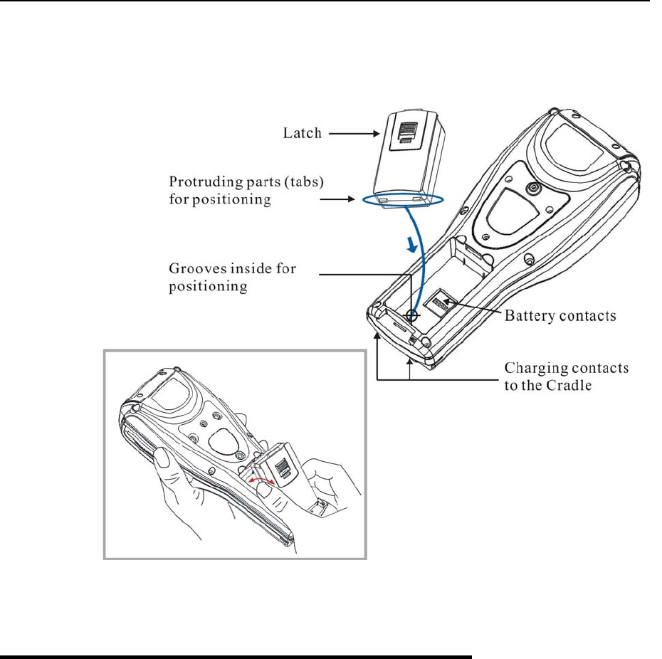
2.1 Battery Pack
1 Place the terminal face down on a flat and clean surface.
2 Slide the battery pack into the battery compartment at a proper angle (30°~45°) so that
the tabs on the bottom of the battery are hooked in the grooves of the compartment.
Make sure that the battery is snugly fit into the compartment.
3 Hold the terminal still and slide the battery latch to lock the battery in the compartment.
Note: For a new battery, make sure it is fully charged before use.
24 Industrial CPT-8500 Reference Manual
Figure 8: Installing battery pack
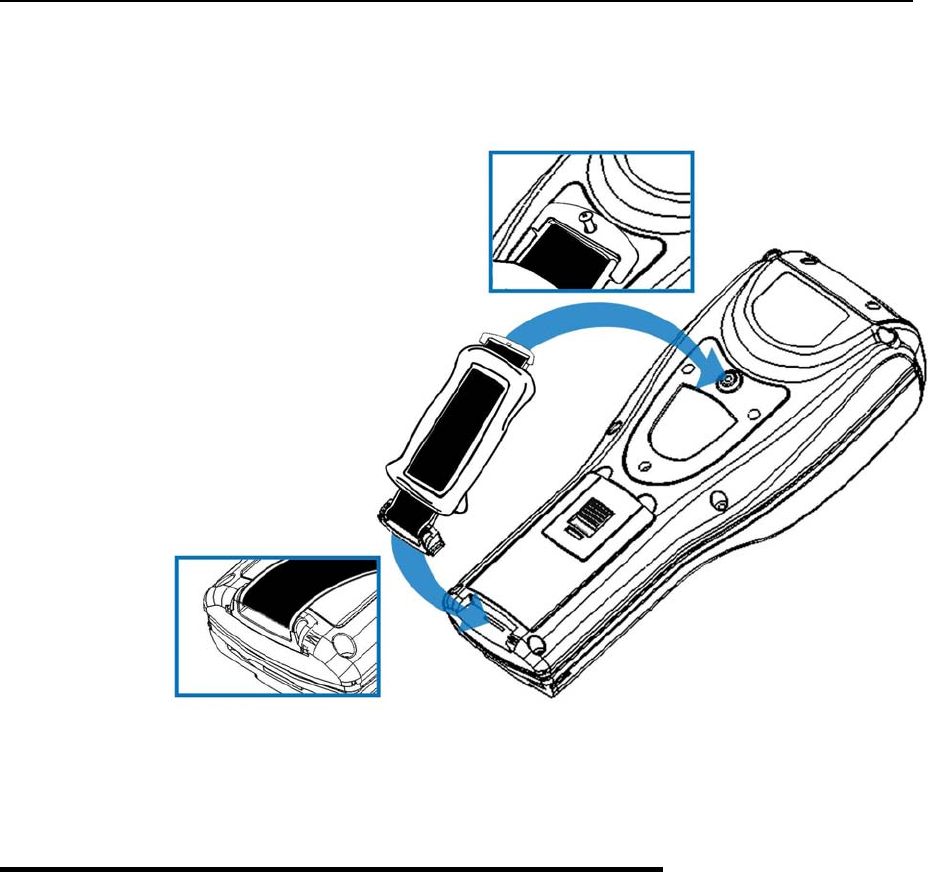
2.2 Hand Strap
When a hand strap is necessary, install it to the terminal by following the steps:
1 Place the terminal face down on a flat and clean surface.
2 Screw one end of the hand strap to the shield-like cover on the back of the terminal.
3 Insert and hook the other end of the hand strap to the bottom of the terminal.
4 Make sure the hand strap is securely attached to the terminal.
5 Adjust the length of the hand strap to suit your handbreadth.
Chapter 2 Installing CPT-8500 25
Figure 9: Installing hand strap
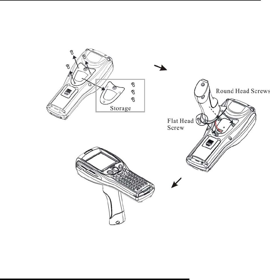
2.3 Pistol Grip
When a pistol grip is necessary, install it to the terminal by following the steps:
1 Place the terminal face down on a flat and clean surface.
2 Remove the shield-like cover on the back of the terminal by unscrewing.
If there is a hand strap installed, remove it first. Keep the cover and screws for future use
when the pistol grip is not desired.
3 Connect the power connector from the pistol grip to the receptacle on the terminal.
4 Screw the pistol grip to the shield-like cover.
5 Make sure all screws are tightened up but not over-tightened to damage the threads.
6 Turn ON the terminal and test the trigger.
26 Industrial CPT-8500 Reference Manual
Figure 10: Installing pistol grip
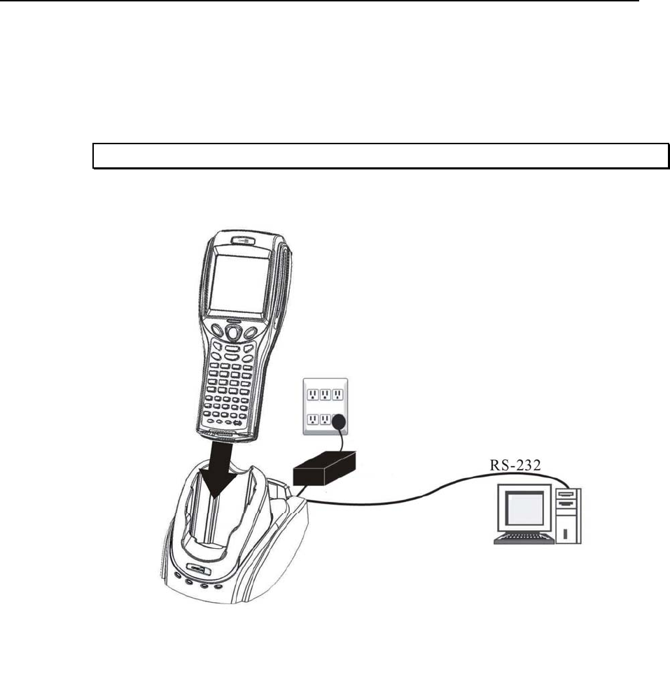
2.4 Cradle, serial or modem
For charging and communications at the same time, a cradle is necessary.
1 Place the cradle in a flat and clean surface.
2 Connect the line of the power adaptor to the power jack on the back of the cradle.
3 Connect the power adaptor to a suitable power outlet.
4 The cradle is ready for charging.
5 If data communications are desired at the same time, connection must be established as
well. This depends on the cradle type.
Chapter 2 Installing CPT-8500 27
For example, below illustrates an RS-232 cable connected between a computer and the
cradle. The interface between the terminal and the cradle is serial IR that can run data in
a higher speed than IrDA.
Note: Make sure the connection is made secured.
Figure 11: Setting up cradle

28 Industrial CPT-8500 Reference Manual
2.4.1 Cradle Options
The choice of cradle can be very flexible. Choose a suitable type that best meets your needs.
Note: The cradle is designed for communications and charging at the same time.
Type (by communication Interface) Package Contents
Serial Cradle
(RS-232 only)
Cradle
Power adaptor
Spare battery pack
RS-232 cable
Charging &
Communications
Cradle
Modem Cradle
(RS-232 + 56kbps Modem)
Cradle
Power adaptor
Spare battery pack
RS-232 cable
Phone cable
Optional Accessory RS-232 to USB adaptor (converter)
Chapter 2 Installing CPT-8500 29
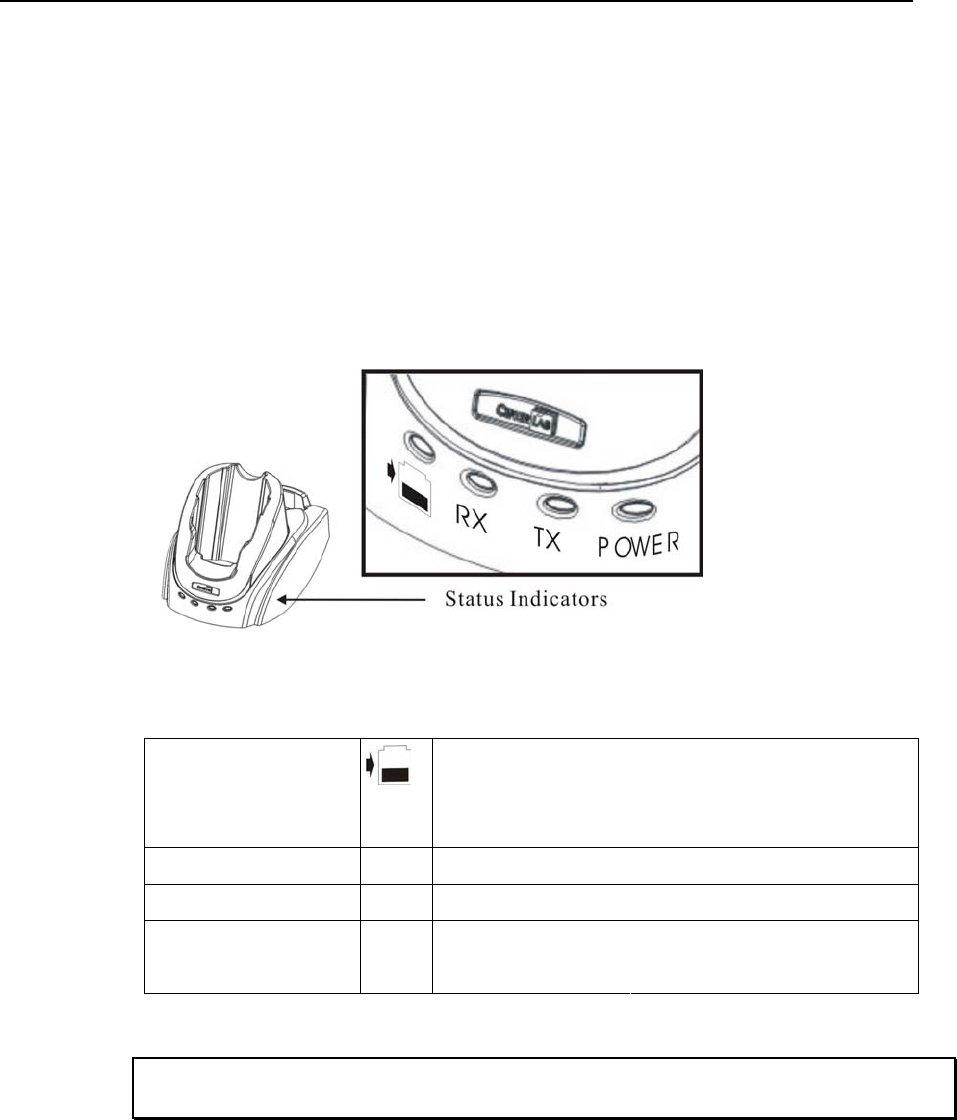
2.4.2 Status Indicators
¾ Charging Status
For main battery, view the screen of the CPT-8500.
For spare battery, see cradle LEDs.
¾ Communications & Port Status
See cradle LEDs: RX, TX and Power.
Figure 12: Cradle LEDs
Charging Spare Battery Red LED: Charging
Green LED: Charging completed
Flashing (Red/Green): Error occurs
Receiving Data RX Red LED: Receiving data from a host
Transmitting Data TX Red LED: Transmitting data to a host
Power Red LED: RX/TX via modem port
Power
Green LED: RX/TX via RS-232 port
Warning! Charging error may occur due to a power failure or defected battery
contacts.
30 Industrial CPT-8500 Reference Manual
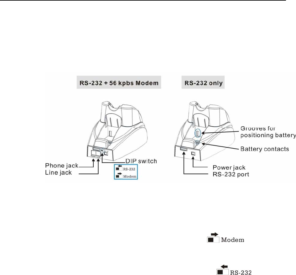
2.4.3 DIP Switch
The modem cradle (left) integrates a modem to the original serial cradle (right). Through
toggling the DIP switch, the modem cradle can make use of the modem or RS-232 port for
flexibility in connection.
Figure 13: Cradle - DIP switch
¾ Modem connection
Activate the modem by sliding the dip switch to right:
¾ RS-232 connection
Activate the RS-232 port by sliding the dip switch to left:

Chapter 2 Installing CPT-8500 31
2.5 Charging
2.5.1 Cradle
After being set up, the cradle is ready for charging the terminal (loaded with main battery)
and one spare battery pack.
Seat the terminal and/or the spare battery pack then.
2.5.2 Gang Charger
If you have purchased the 4-bay gang charger, you can charge up to four batteries at the
same time. This is particularly convenient for a non-stop operation or locations where a
proper power supply is unavailable.
Note: The battery is fully charged after approximate 4 hours.
2.6 Communications
For the CPT-8500, it is capable of sending or receiving data in a number of different ways.
32 Industrial CPT-8500 Reference Manual
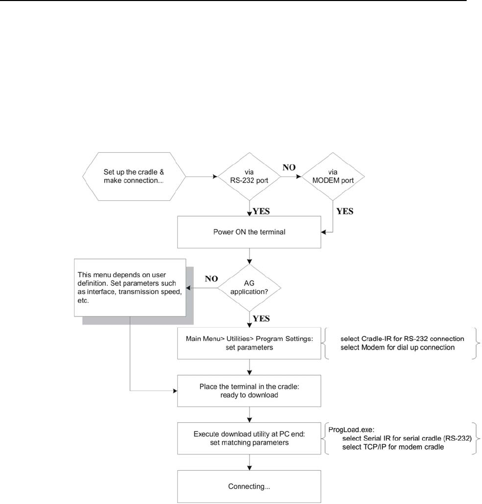
2.6.1 Wired
The terminal is capable of wired communications via:
Serial cradle
Modem cradle
See the following flow chart for instructions on the procedure.
Figure 14: Flow chart of cradle communications

Chapter 2 Installing CPT-8500 33
¾ Serial Cradle (RS-232)
When the cradle is set up,
1 Connect one end of a RS-232 cable to the RS-232 port on the back of the cradle.
2 Connect the other end of the cable to the RS-232 port of a host computer.
3 See the flow chart for the rest steps.
¾ Modem Cradle
When the cradle is set up,
1 For communications via an internal modem, slide the DIP switch on the back of the
cradle to right.
2 Connect the telephone line to the [Line] jack on the back of the cradle.
3 You may connect the cradle to a telephone through the [Phone] jack.
4 See the flow chart for the rest steps.
2.6.2 Wireless
The terminal is capable of wireless communications via the following technologies:
IrDA
Bluetooth
IEEE 802.11b
GSM/GPRS
Refer to 1.3.10 Wireless Support for more details.
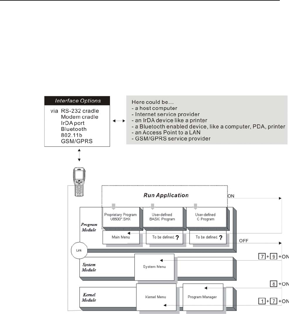
34
The software inside the terminal mainly consists of three modules: Kernel, System, and
Program.
Figure 15: Software Architecture
In This Chapter
3.1 Program Module .......................................................... 35
3.2 System & Kernel Modules........................................... 36
CHAPTER 3
Software Architecture

Chapter 3 Software Architecture 35
3.1 Program Module
¾ Preloaded Application
The terminal is preloaded with a proprietary application program, that is, the AG Runtime
(U8500*.SHX). After being physically set up and configured properly through the
proprietary Application Generator (AG8500m.exe), the terminal is ready to collect data.
The main menu is generated by the AG Runtime, U8500*.SHX.
¾ Alternative
In addition to the proprietary application development tool, the Application Generator, you
may develop your own application program through BASIC or C complier, in order to best
meet your system requirements.
Proprietary Application Program
9 The terminal is preloaded with U8500*.SHX, which is for use with the matching application
development tool at PC end, AG8500m.exe.
9 The Application Generator (AG) software package includes this application development tool and
several associated utilities to make it versatile in use.
Alternatives:
9 Aided by programming support, user-defined application programs can be developed to satisfy
specific needs, such as being integrated into an existing system.

36 Industrial CPT-8500 Reference Manual
3.2 System & Kernel Modules
For system configurations and managing multiple programs, each terminal comes with the
System Menu, Kernel Menu, and Program Manager.
¾ System Menu
This is generated by the System module. You may configure parameters, test components,
download or update the active application program (the one with the Program module), and
download one custom font file.
¾ Kernel Menu
This is generated by the Kernel module. Generally, you may update the core program
(Kernel Update), download or update the active application program (the one with the
Program module), download one custom font file, and configure Bluetooth settings.
¾ Program Manager
This is also generated by the Kernel module. The Program Manager is bundled with the
Kernel Menu. You may download as many as seven application programs, as well as one
custom font file.

37
This section mainly describes the alternatives to configure the CPT-8500 terminal,
including hardware configuration and downloading application programs.
In This Chapter
4.1 System Menu ............................................................... 38
4.2 Program Manager ........................................................ 70
4.3 Kernel Menu ................................................................ 75
CHAPTER 4
Configuring CPT-8500
38 Industrial CPT-8500 Reference Manual
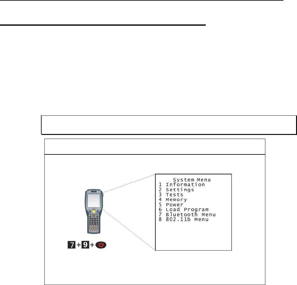
4.1 System Menu
The System Menu is generated by a powerful utility, which offers an interface for engineers
(programmers or system integrator) to view system information, change the configuration
parameters, download programs and run diagnostics.
This menu is designed for engineering tests and maintenance ONLY. For this reason, the
System Menu provides password protection to prevent unauthorized users from
accidentally changing system settings.
Warning! The System Menu is NOT for the use of any end users. The system
password helps ensure system safety and integrity.
How to access the System Menu?
Chapter 4 Configuring CPT-8500 39
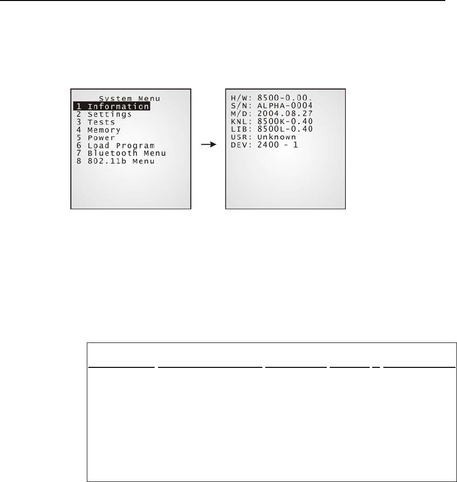
4.1.1 Information
The information provided here helps diagnose the system.
H/W: Hardware version (PCB)
S/N: Serial number of the terminal
M/D: Manufacturing date
KNL: Kernel version
LIB (BSC): C library or BASIC run-time version
USR: Application program version
DEV: Code for optional hardware configurations, i.e. 2400-1
2 4 0 0 - 1
Type of Reader
Type of Wireless Module
RFID Module
Reserved
Keyboard layout
0= none
1= CCD
2= Laser
3= 2D
0= none
3= GSM (+ Bluetooth
4= 802.11b (+ Bluetooth)
5= Bluetooth only
7= GSM + 802.11b (+
Bluetooth)
0= none
1= RFID
0= 24-key
1= 44-key
40 Industrial CPT-8500 Reference Manual
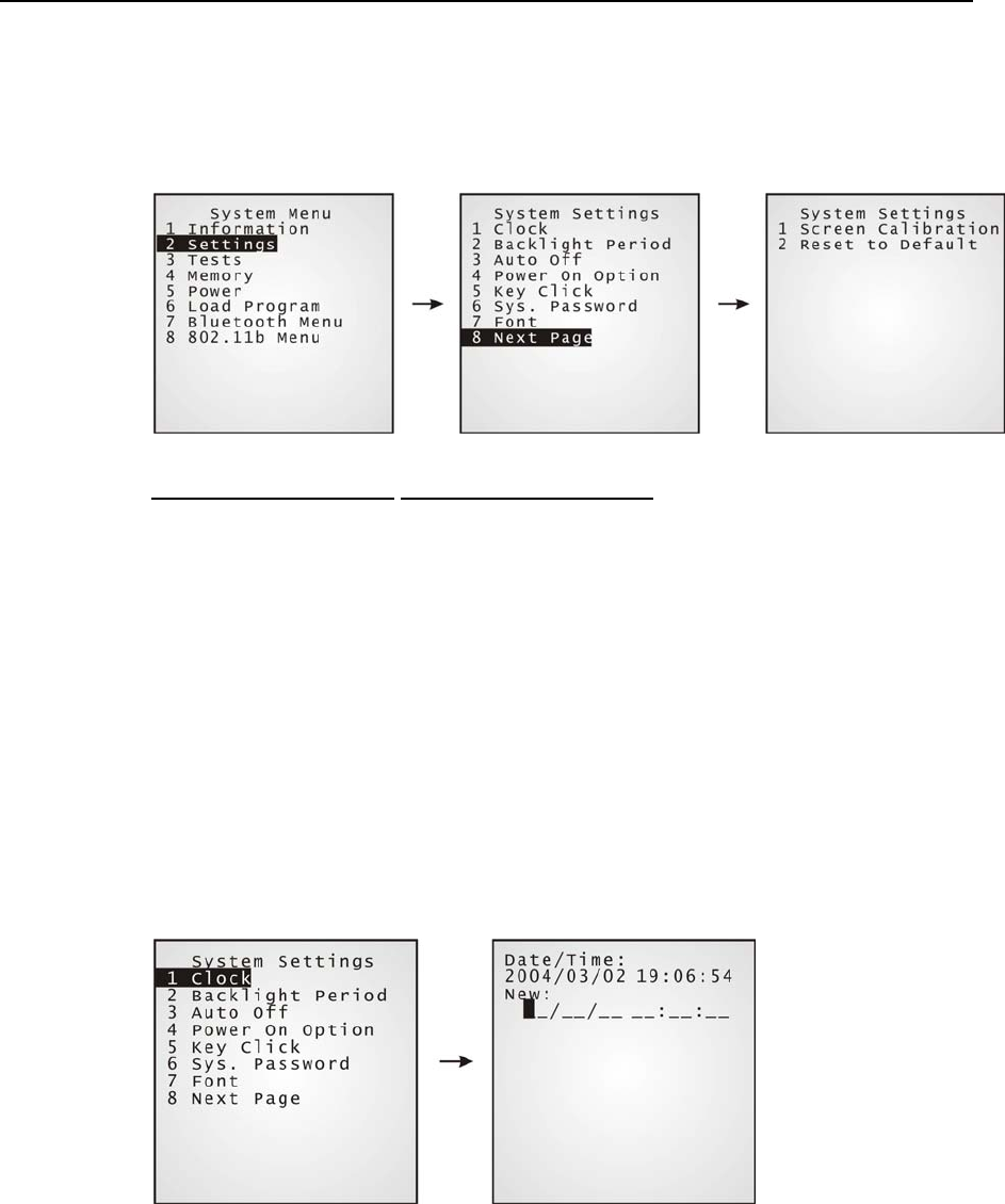
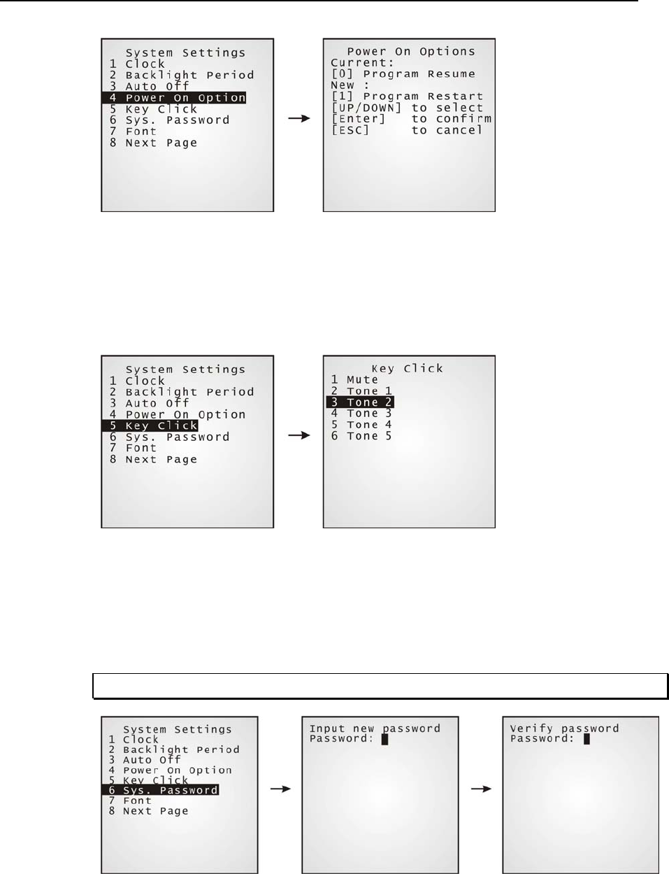
4.1.2 Settings
Here provides options to change the default settings.
System Settings Default Values
Clock blank
Backlight Period 20 seconds
Auto Off 10 minutes
Power On Options Program Resume
Key Click Tone 2
System Password Open access
Font System font
¾ Settings > Clock
Set date and time for Real Time Clock. Enter two digits for the year, i.e. 04 for 2004.
Chapter 4 Configuring CPT-8500 41
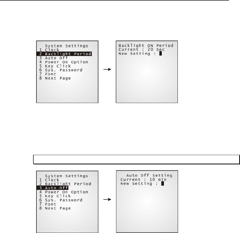
¾ Settings > Backlight Period
Set the backlight duration for the keypad and LCD. Enter a value between 0 and 9999.
¾ Settings > Auto Off
Set time threshold for the terminal to automatically power off when no operation is taking
place during that specific period. Enter a value between 0 and 999.
Note: To disable this function, enter 0.
¾ Settings > Power On Options
Set the startup screen right after powering on:
[0] Program Resume: Start from the last session of program before
shutdown.
[1] Program Restart: Fresh start from the first session of the program.
42 Industrial CPT-8500 Reference Manual
¾ Settings > Key Click
There is audible feedback for pressing a key on the keypad. The current value is
highlighted. Select a tone for the buzzer or mute it.
¾ Settings > System Password
Set a password to control user access to the System Menu. The password consists of eight
characters at most.
Note: To disable a previous password, enter blank on the following screens.
Chapter 4 Configuring CPT-8500 43
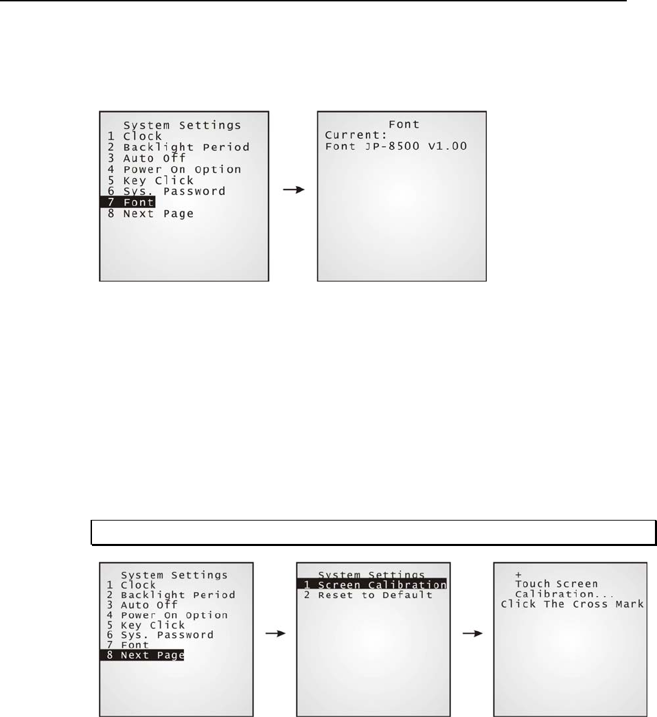
¾ Settings > Font
Current font information can be viewed here.
Default: System font
Custom font file, if there is one
The font settings here can be changed if a "multi-language" font file has been downloaded.
(Press [Up] or [Down] to move the cursor up or down through the menu of options.)
¾ Settings > Screen Calibration
The cross mark will appear on the four corners of the screen for alignment. Use the tip of the
stylus to tap at the center of the cross mark firmly and accurately.
Warning: DO NOT use any pointed or sharp object to move against the screen.
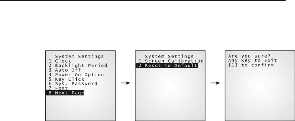
44 Industrial CPT-8500 Reference Manual
¾ Settings > Reset to Default
Reset all settings to the default values. The following dialog box prompts for confirmation.
Chapter 4 Configuring CPT-8500 45
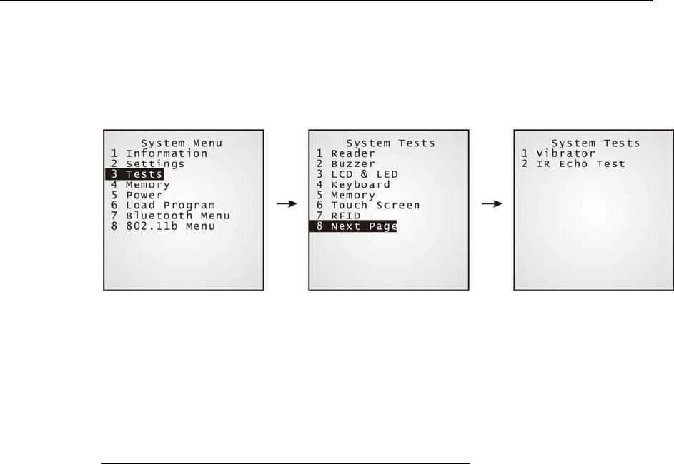
4.1.3 Tests
Here provides functional tests for key parts.
¾ Tests > Reader
Test the reading performance of the scanner, with laser or image scanning engine. Press
[SCAN] to start.
To stop and exit the test, press any key.
The following barcodes are enabled by default:
Code 39
Industrial 25
Interleave 25
Codabar
Code 93
Code 128
UPCE
UPCE with ADDON 2
UPCE with ADDON 5
EAN8
EAN8 with ADDON 2
EAN8 with ADDON 5
EAN13
EAN13 with ADDON 2
EAN13 with ADDON 5
…
Other barcodes must be enabled
through programming.

46 Industrial CPT-8500 Reference Manual
¾ Tests > Buzzer
Test the buzzer with different frequency/duration combinations. Press [Enter] to start. Press
any key to stop and exit the test.
¾ Tests > LCD & LED
Test the LCD display and LED indicator. Press [Enter] to start. Press any key to stop and
exit the test.
¾ Tests > Keyboard
Test the rubber keys. Press any key and its corresponding character will be shown on the screen.
Press [ESC] to stop and exit the test.
¾ Tests > Memory
Test the data memory (SRAM), and the results will be shown on the screen. Press any key to
exit.
Warning! The contents of the data memory (SRAM) will be wiped out after test.
¾ Tests > Touch Screen
Test signature capture by using the stylus for handwriting. Press [Enter] to start. Press
[ESC] to stop and exit the test.
¾ Tests > RFID
Test the reading performance of the RFID reader when a proximity card is present. Press
[ESC] to stop and exit the test.
¾ Tests > Vibrator
Test the vibrator. Press [ESC] to stop and exit the test.
¾ Tests > IR Echo Test
The echo test is to verify connectivity between the terminal and the cradle (serial IR). Run
the echo test at baud rate 38400. Press [ESC] to stop and exit the test.
Chapter 4 Configuring CPT-8500 47
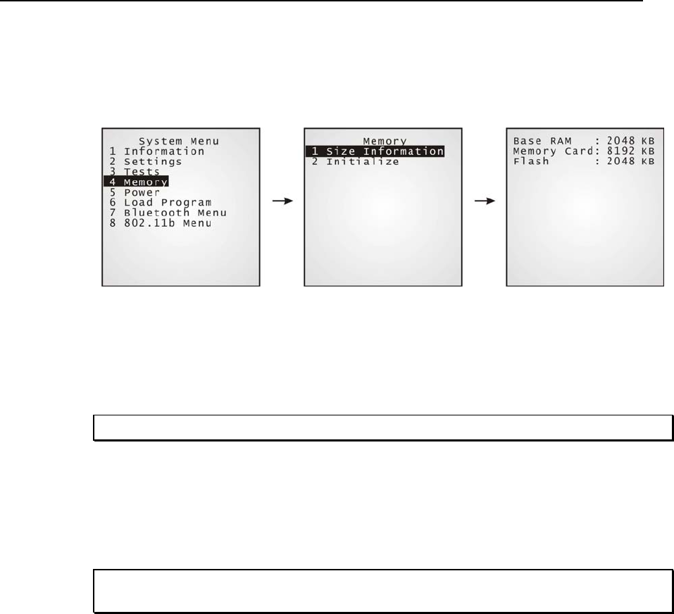
4.1.4 Memory
Here provides information and initialization function of the memory.
¾ Memory > Size information
Base RAM (SRAM for data memory)
Memory Card (SRAM for data memory)
Flash (for program memory)
Note: If memory card is present, it will replace Base RAM in use.
¾ Memory > Initialize
Initialize the data memory, Base RAM or Memory Card.
Warning! The contents of the data memory (SRAM) will be wiped out after memory
initialization.
48 Industrial CPT-8500 Reference Manual
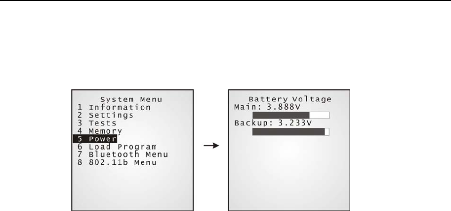
4.1.5 Power
Here shows current voltage consumption.
Main: This refers to the main battery.
It shows dynamic status of the battery pack, as the main power
source.
Backup: This refers to the backup battery.
It shows dynamic status of the button cell, which is used to
retain data in SRAM.
Chapter 4 Configuring CPT-8500 49
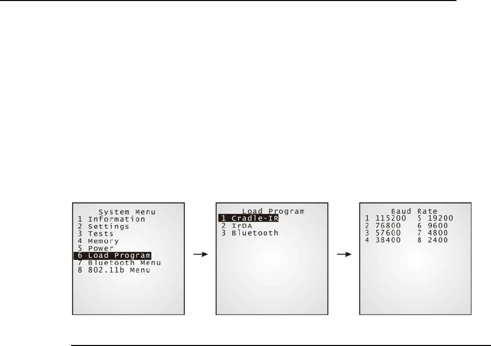
4.1.6 Load Program
Download program or font file to the active memory bank.
New application program
Program update
Font file, i.e. multi-language font
¾ Results
Success: the new program or font file will be activated right after downloading.
Failure: the terminal will resume to the current application program or system font.
Interface
Cradle-IR The communication parameters at PC end should be set accordingly.
IrDA Point to the target IrDA device.
Bluetooth Approach to the target Bluetooth enabled device.

50 Industrial CPT-8500 Reference Manual
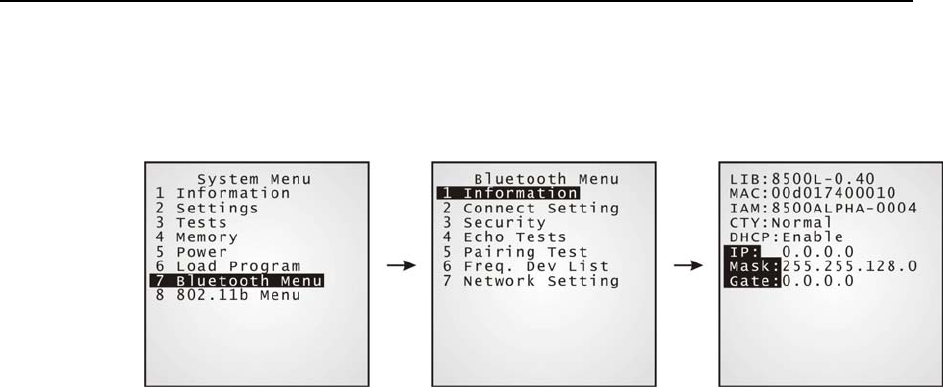
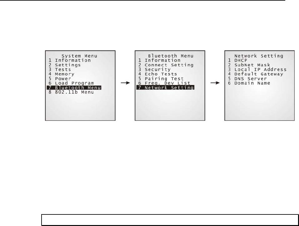
4.1.7 Bluetooth Menu
This submenu is for the built-in Bluetooth technology to work with other Bluetooth enabled
devices. Parameters must be configured correctly.
Bluetooth Menu: Settings: Default Values
Local Name blank
Remote Name blank
Broadcast Me Enable
Connect Setting
Power Saving Enable
Authentication Disable
Security
PIN Code blank
DHCP Enable
SubNet Mask 255.255.128.0
Local IP Address 0.0.0.0
Default Gateway 0.0.0.0
DNS Server 0.0.0.0
Network Setting
Domain Name blank
Chapter 4 Configuring CPT-8500 51
¾ Bluetooth Menu > Information
Information of network configuration can be viewed here.
LIB (BSC): C library or BASIC run-time version
MAC: MAC ID of the Bluetooth module
IAM: A name given to the terminal for identification.
CTY: “Normal” means frequency range is 2.4 ~ 2.5 GHz.
There are bandwidth limitations for 2.4 GHz ISM band in
some countries. For example, only 23 RF channels defined
instead of 79 RF channels in Japan, Spain and France.
DHCP: DHCP being enabled or disabled.
IP: IP address of the terminal
Mask: Subnet Mask
Gate: Default Gateway
52 Industrial CPT-8500 Reference Manual
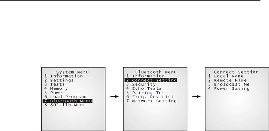
¾ Bluetooth Menu > Connect Setting
A basic Bluetooth system can be configured as (1) point to point and (2) point to multi-point
(Piconet; up to seven slaves can be connected to a master).
Set the following parameters.
Local Name: Enter a name for identifying the terminal.
Remote Name: Enter a name for making specific connection.
The remote name must be one of those in the Freq. Dev. List.
Otherwise, the terminal will fail to make connection with any
device. DO NOT specify any remote name when roaming is
required.
Broadcast Me: Options - Enable or Disable
For initial connection, broadcasting must be enabled. For
security reason, simply disable it to hide the terminal from
other Bluetooth devices.
Power Saving: Options - Enable or Disable
This refers to the low power consumption mode. Only the
Sniff mode is supported.
Chapter 4 Configuring CPT-8500 53
54 Industrial CPT-8500 Reference Manual
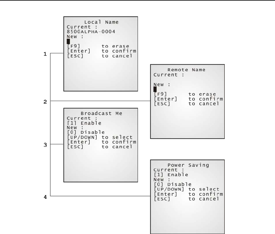
¾ Bluetooth Menu > Security
Set up or modify security parameters:
Authentication: Options - Enable or Disable
PIN Code: Define the encryption key values. Up to 13 characters, using
ASCII code.
Chapter 4 Configuring CPT-8500 55
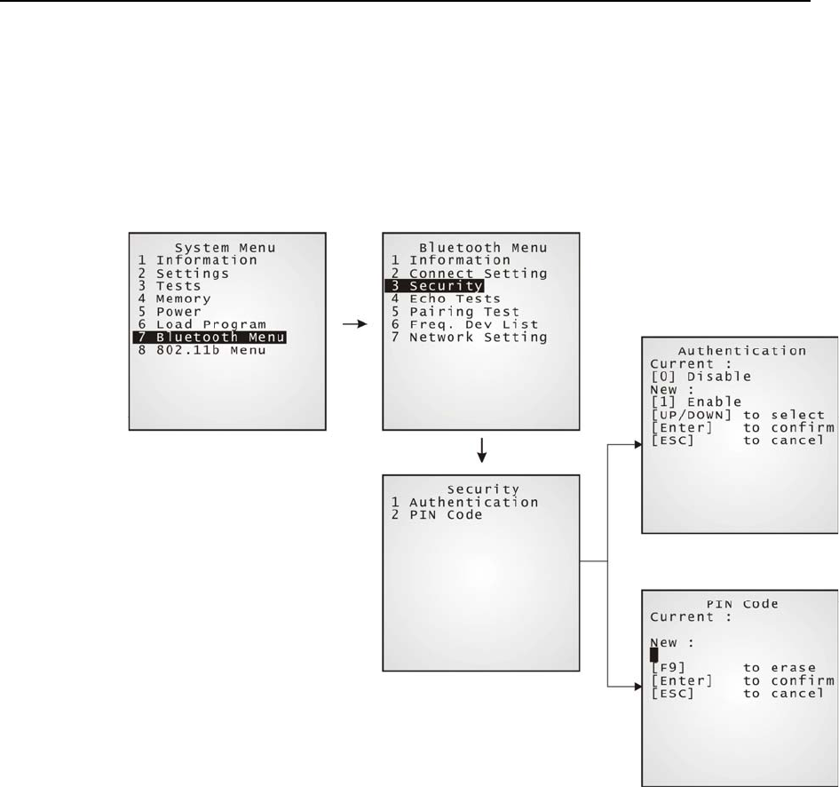
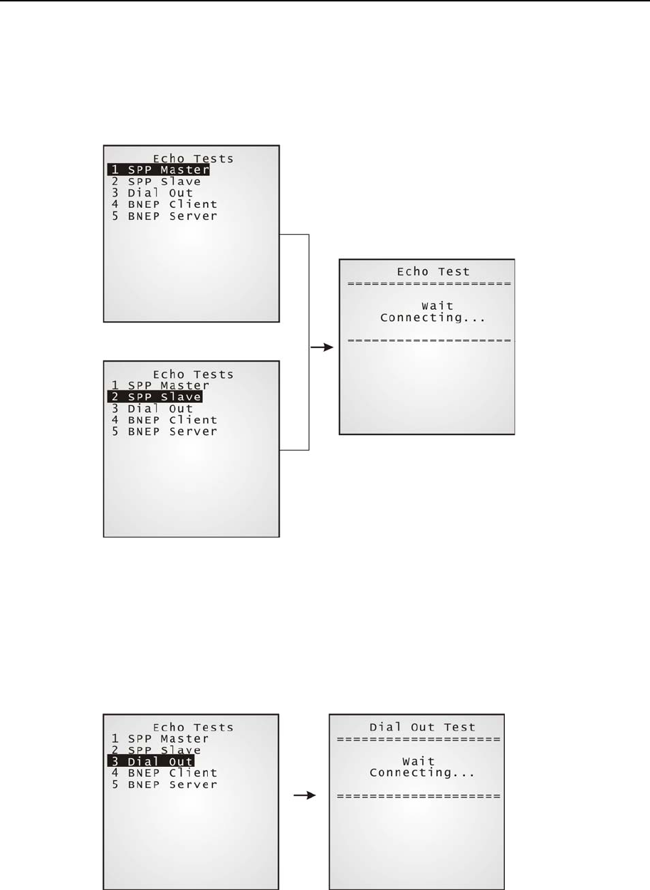
¾ Bluetooth Menu > Echo Tests
Echo tests are used for verifying connectivity to make sure the terminal is within coverage.
Press [ESC] to stop and exit the test.
For PAN mode, it helps estimate the number of APs and terminals, and determine the
topology of deploying APs.
“SPP”: Serial Port Profile - for ad hoc networking, without going
through any access point.
“Dial Out”: For Dial-Up Networking Profile, also known as DUN. It
makes use of a Bluetooth modem or mobile phone as a
wireless modem.
“PAN(BNEP)”: Personal Area Networking Profile - uses Bluetooth Network
Encapsulation Protocol for IP networking over Bluetooth.
Note: You also need a test utility on PC to test the networking.
56 Industrial CPT-8500 Reference Manual
SPP Master: Set the terminal as a master device.
It is to be followed by an attempt to make connection.
SPP Slave: Set the terminal as a slave device.
It is to be followed by an attempt to make connection.
Dial Out Set the terminal as a modem.
It is to be followed by an attempt to make connection with the
target device. The target device may be a mobile phone or
Bluetooth modem.
Chapter 4 Configuring CPT-8500 57
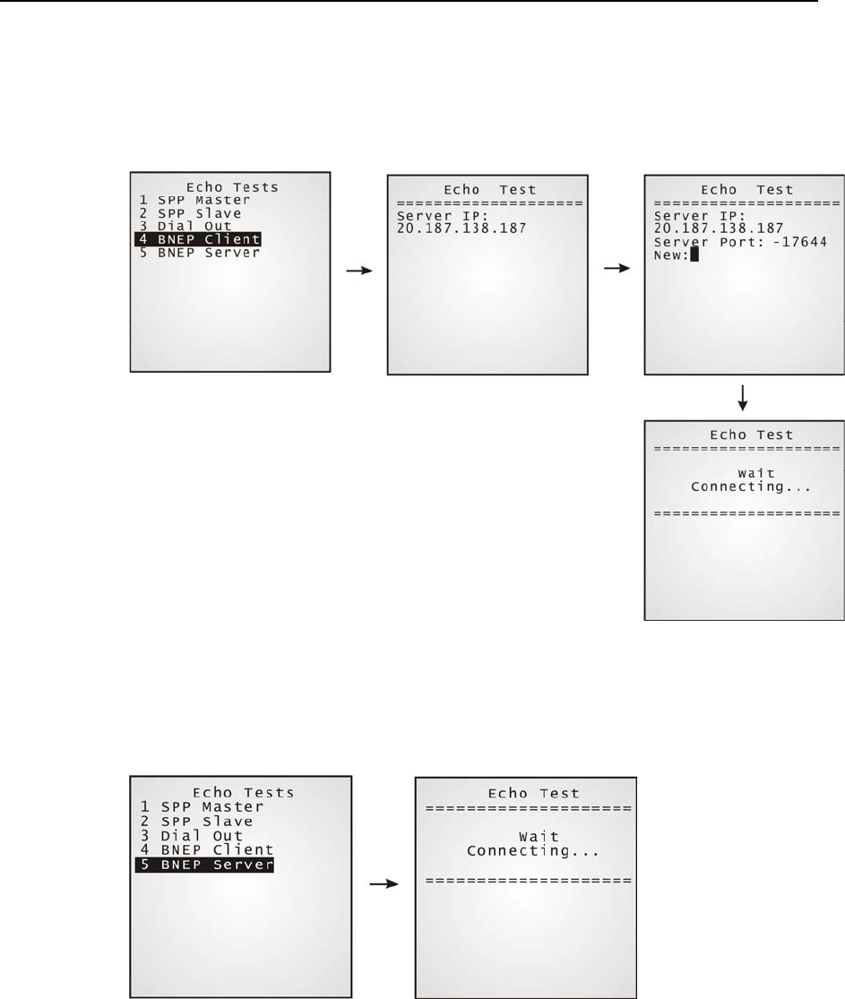
PAN(BNEP)
Client:
Set the terminal as a client.
Enter the IP address of a server that connection is desired.
It is to be followed by an attempt to make connection with
APs.
PAN(BNEP)
Server:
Set the terminal as a server.
It is to be followed by an attempt to make connection with
APs.
58 Industrial CPT-8500 Reference Manual
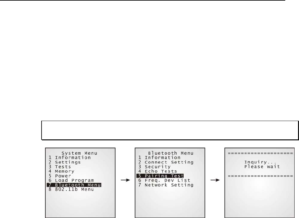
¾ Bluetooth Menu > Pairing Test
Pairing is for the creation and exchange of a link key between two devices. The devices use
the link key for future authentication when exchanging information.
After inquiry, there will be a “Target Machine” menu for selecting mode:
Serial Port (SPP)
Access Point (PAN)
Dial Up Network (DUN)
Press [ESC] to stop and exit the test.
Note: For initial setting of Bluetooth system, pairing must be carried out before the Echo
tests.
Chapter 4 Configuring CPT-8500 59
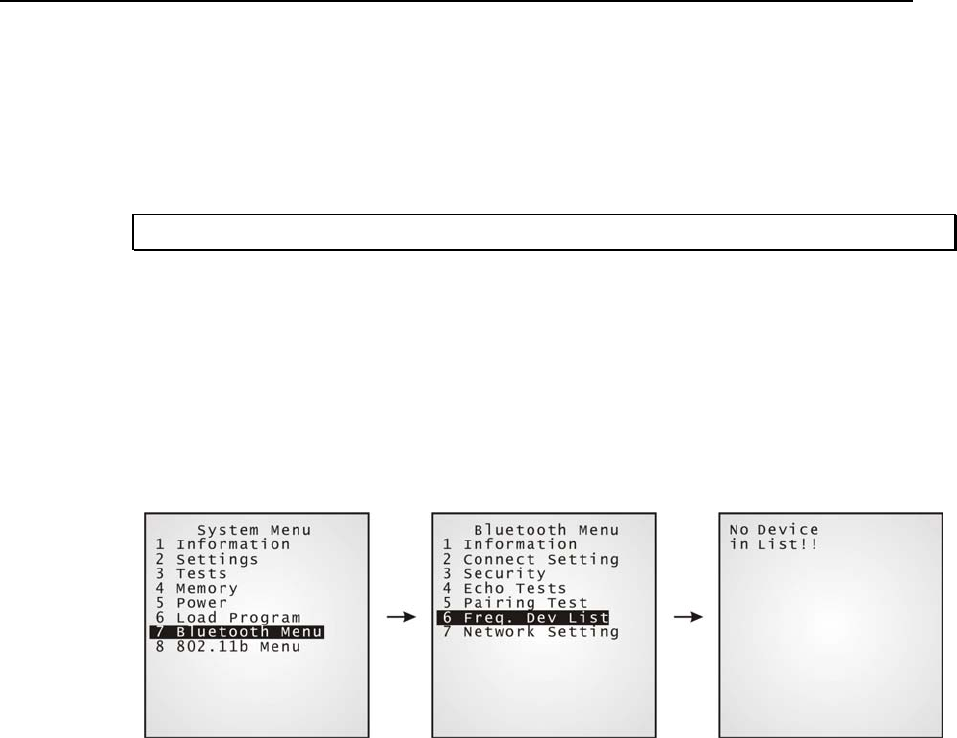
¾ Bluetooth Menu > Freq. Dev. List
After successful pairing test, it will generate a list of device/s that the terminal has been
connected to lately. During roaming or making new connection, the terminal will
automatically connect to the listed device/s.
Note: To un-pair any device, simply delete the device from this list.
SPP mode (Serial Port Profile): Only one device listed for quick
connection.
DUN mode (Dial-Up Networking): Only one device listed for quick
connection.
AP mode (PAN - IP Networking): Up to eight APs listed for roaming
purpose.
60 Industrial CPT-8500 Reference Manual
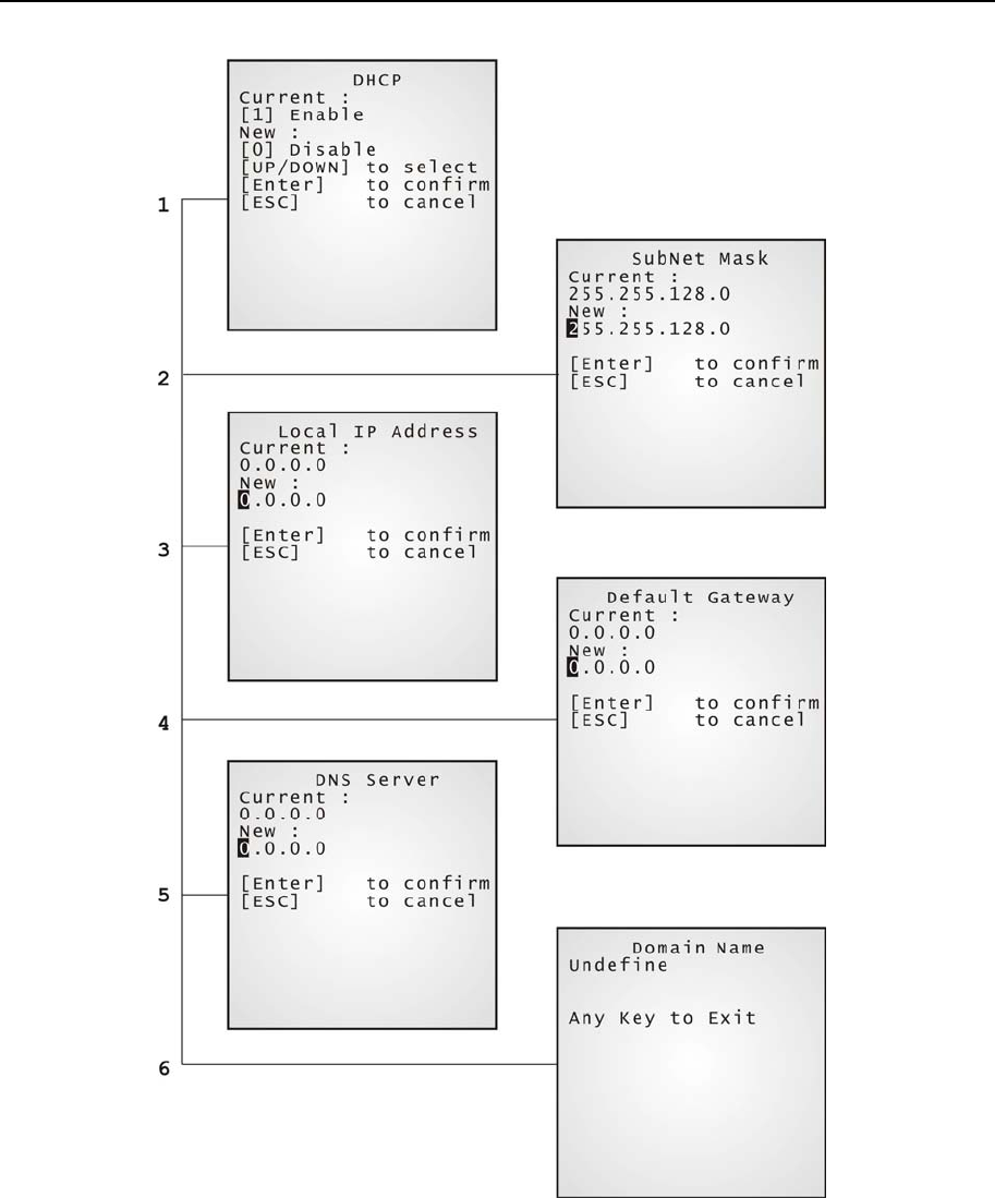
¾ Bluetooth Menu > Network Setting
Set network parameters:
DHCP: Options - Enable or Disable
SubNet Mask: Enter a new Mask IP, if necessary.
Local IP Address: Enter a new address for the terminal, if necessary.
Default Gateway: Enter a new address for the default Gateway, if
necessary.
DNS Server: Enter a new address for the DNS server, if
necessary.
Domain Name: The domain name of the host is shown here.
Note: All of the setting could be obtained form DHCP server if DHCP is activated.
Chapter 4 Configuring CPT-8500 61

62 Industrial CPT-8500 Reference Manual
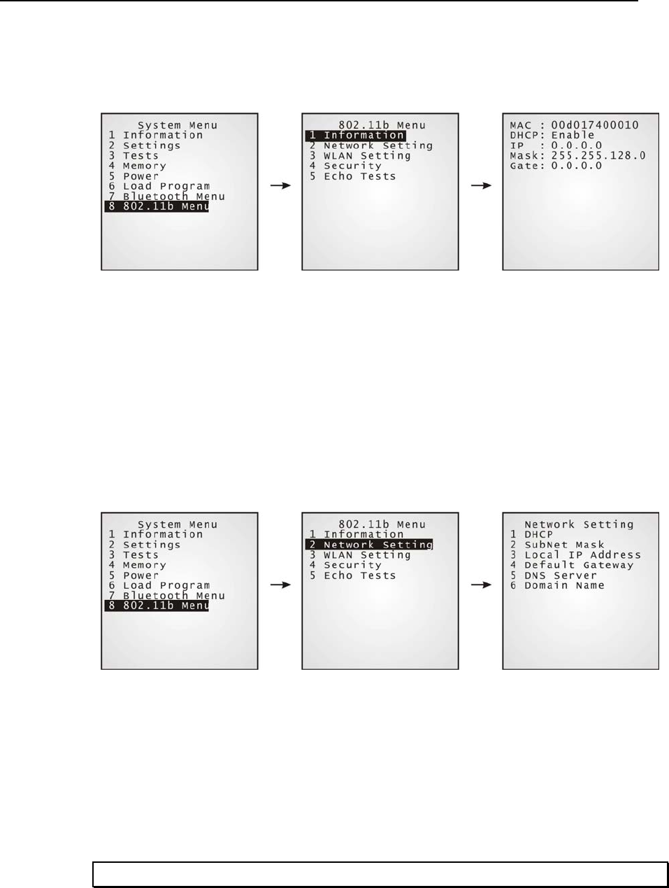
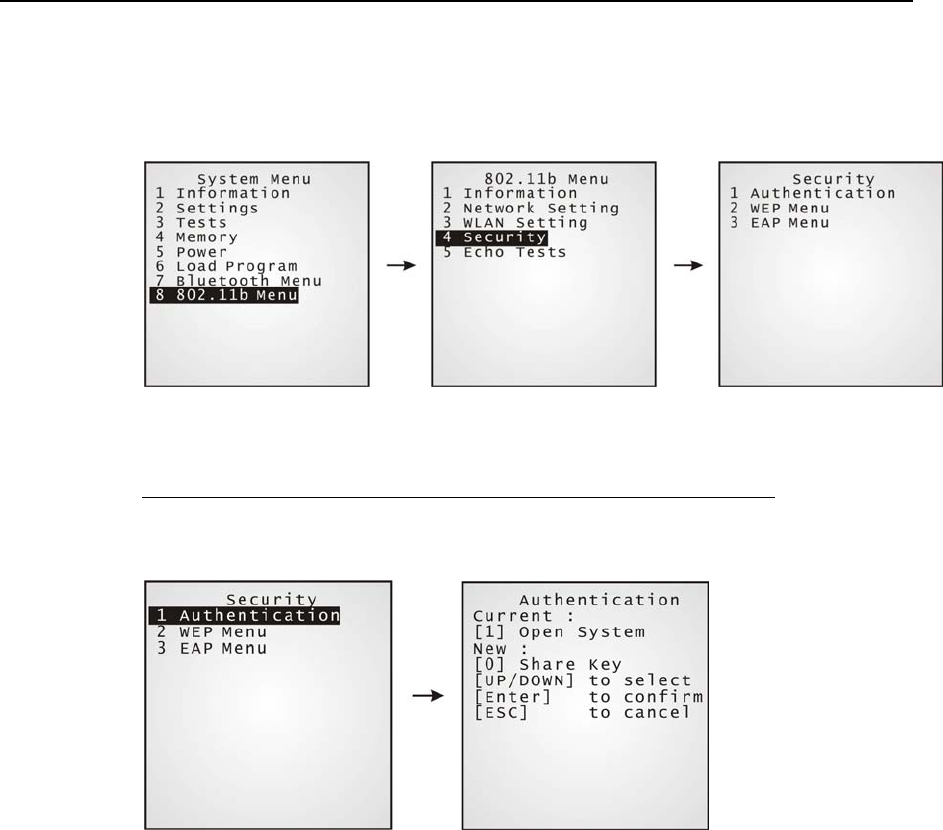
4.1.8 IEEE 802.11b Menu
This submenu is for IEEE 802.11b wireless networking. Parameters must be configured
correctly.
Note: This menu is available only when the 802.11b module is installed.
802.11b Menu: Settings: Default Values
DHCP Enable
SubNet Mask 255.255.128.0
Local IP Address 0.0.0.0
Default Gateway 0.0.0.0
DNS Server 0.0.0.0
Network Setting
Domain Name blank
Local Name blank
Domain Name blank
SS ID blank
System Scale Medium
Power Saving Enable
WLAN Setting
Preamble Long
Authentication Open System
WEP Menu Disable
Security
EAP Menu Disable
Chapter 4 Configuring CPT-8500 63
¾ 802.11b Menu > Information
Information of network configuration can be viewed here.
MAC: MAC ID of the 802.11b module
DHCP: DHCP being enabled or disabled
IP: IP address of the terminal
Mask: Subnet Mask
Gate: Default Gateway
¾ 802.11b Menu > Network Setting
Set general network parameters.
DHCP: Options - Enable or Disable
SubNet Mask: Enter a new Mask IP, if necessary.
Local IP Address: Enter a new address for the terminal, if necessary.
Default Gateway: Enter a new address for the default Gateway, if
necessary.
DNS Server: Enter a new address for the DNS server, if necessary.
Domain Name: The domain name of the host is shown here.
Note: All of the setting could be obtained form DHCP server if DHCP is activated.
64 Industrial CPT-8500 Reference Manual
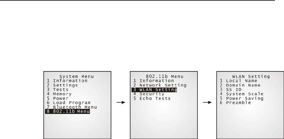
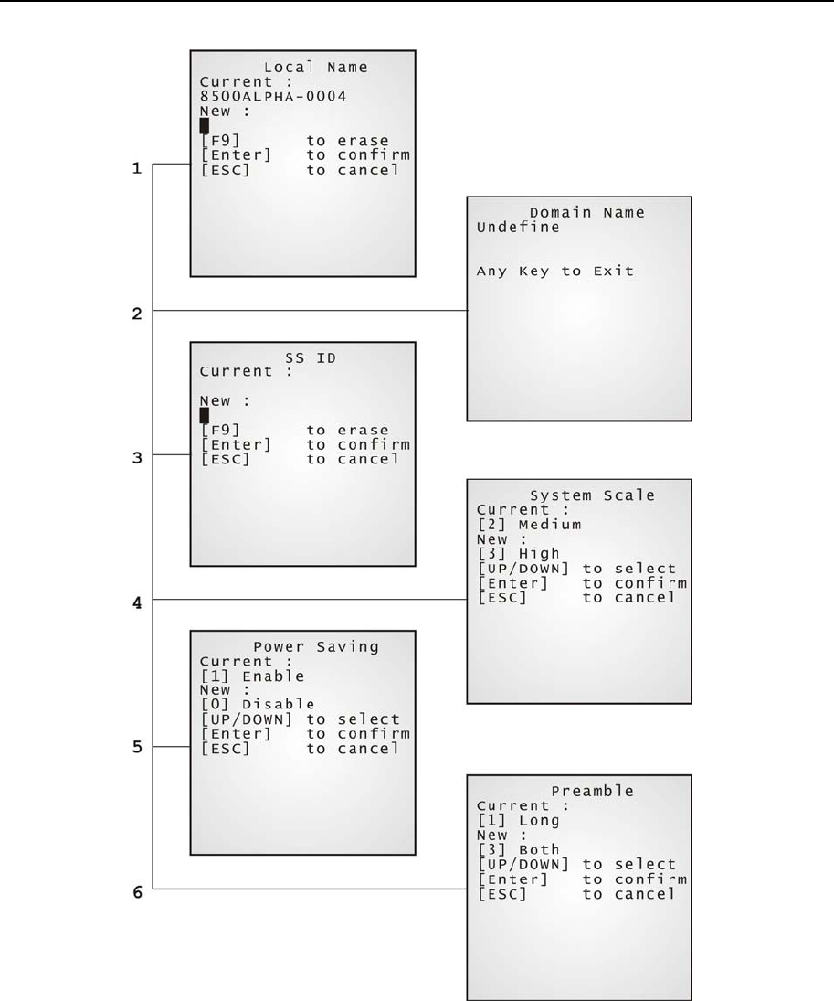
¾ 802.11b Menu > WLAN Setting
802.11b system can operate in two modes (1) Ad-hoc mode: peer-to-peer, and (2)
Infrastructure mode: point to multi-point through access points.
Set the following parameters.
Local Name: Enter a name for identifying the terminal.
Domain Name: The domain name of the host is shown here.
SS ID: This refers to Service Set ID or Identifier.
The terminal can ONLY communicate with access
points that have the same SS ID
System Scale: This refers to Access Point Density.
Options - [1] Low [2] Medium [3] High
The value you set must match that set for the access
point.
Power Saving: This refers to the low power consumption mode.
Options - Enable or Disable
The value you set must match that set for the access
point.
Preamble: Options - [1] Long [2] Short [3] Both
The value you set must match that set for the access
point.
Chapter 4 Configuring CPT-8500 65
66 Industrial CPT-8500 Reference Manual
¾ 802.11b Menu > Security
Set up or modify security parameters:
Authentication
[1] Open System:
[0] Share Key:
Default authentication type
This requires implementing WEP key.
Chapter 4 Configuring CPT-8500 67
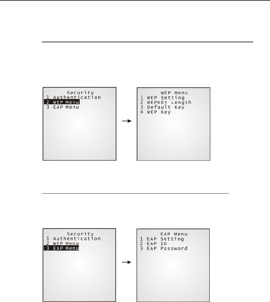
WEP Menu
WEP Setting:
WEP Key Length:
Default Key:
WEP Key:
Enable or Disable (for Share Key, it must be enabled.)
64 or 128 bits
WEP KEY1
Enter settings for WEP KEY (1, 2, 3 or 4)
EAP Menu
EAP Setting:
EAP ID:
EAP Password:
Enable or Disable
Enter a user name, up to 32 characters
Enter a password, up to 32 characters
68 Industrial CPT-8500 Reference Manual
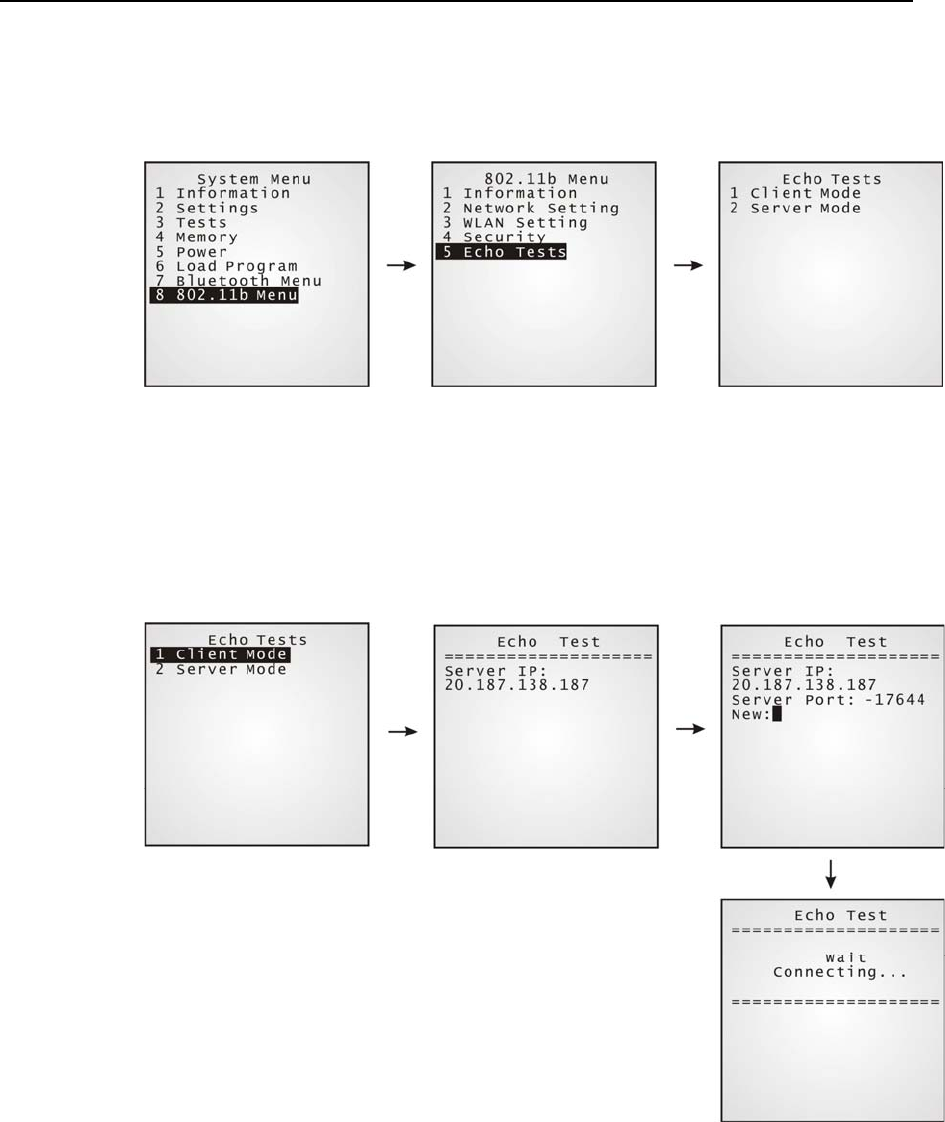
¾ 802.11b Menu > Echo Tests
Echo tests are used for verifying connectivity to make sure the terminal is within coverage.
Client Mode: Set the terminal as a client.
Enter the IP address of a server that connection is
desired.
It is followed by an attempt to make connection with
APs.
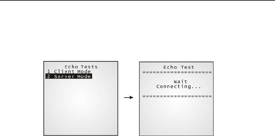
Chapter 4 Configuring CPT-8500 69
Server Mode: Set the terminal as a server.
It is followed by an attempt to make connection with
APs.
70 Industrial CPT-8500 Reference Manual
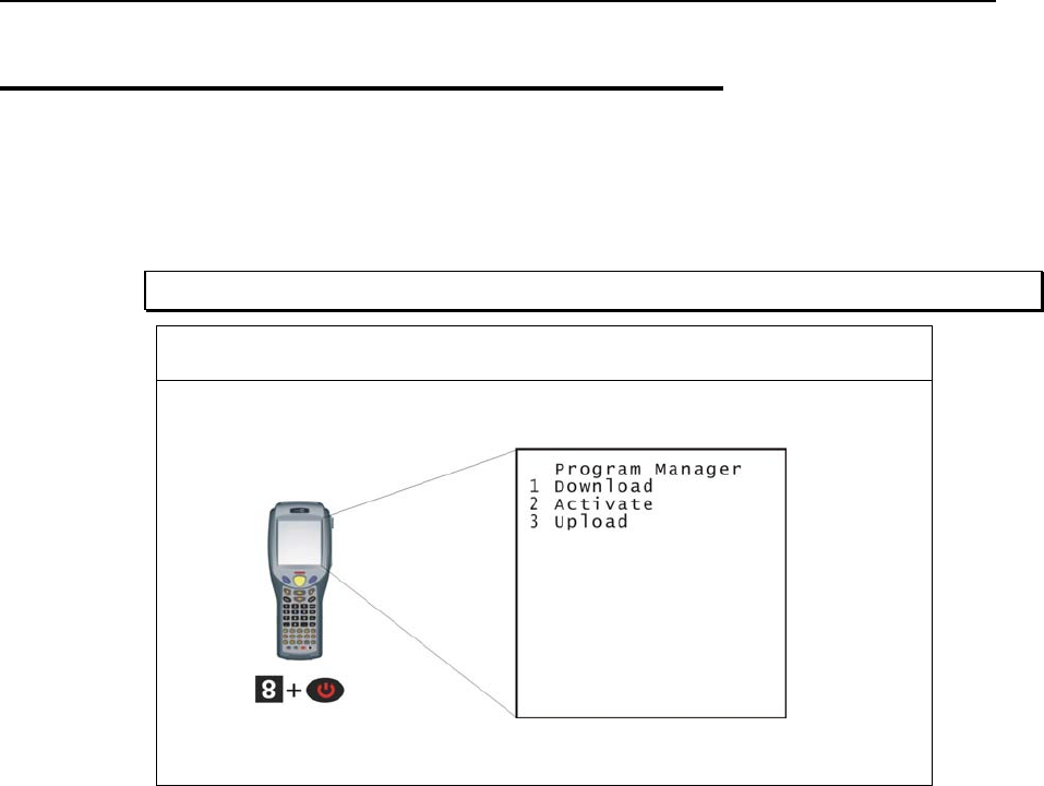
4.2 Program Manager
The CPT-8500 terminal supports multiple applications and languages. In the menu of
Program Manager, it can download up to seven programs and one of them is made active.
Warning! The Program Manager menu is NOT for the use of any end users.
How to access the Program Manager?
Chapter 4 Configuring CPT-8500 71
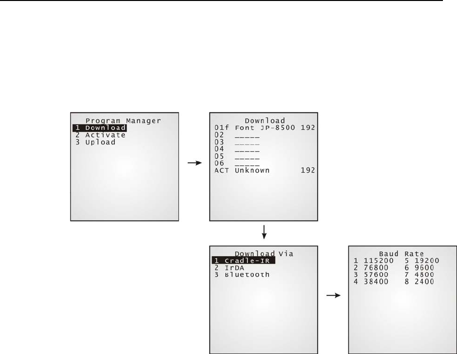
4.2.1 Download
Multiple application programs can be downloaded through a variety of interfaces. Here
brings a full list of programs that are currently stored on the terminal with size information
(program name of 12 characters; size in kilo bytes).
A suffix letter after the memory bank (01~06) indicates the file type of program.
“b” for BASIC program
“c” for C program
“f” for font file
The terminal can store up to seven application programs (including the one in the active
memory bank) and one font file (may not be shown in this list).
72 Industrial CPT-8500 Reference Manual
Figure 16: Downloading through Program Manager
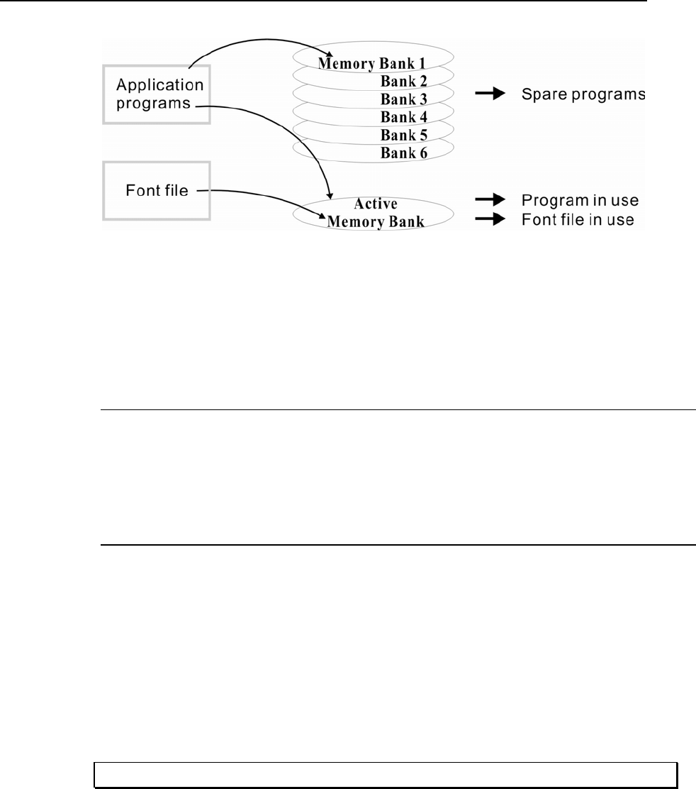
¾ Memory Bank 01 ~ 06
Only application program can be downloaded to these banks.
Empty bank:
1. Select an empty bank by pressing the corresponding number and then [Enter].
2. Select baud rate for downloading.
3. Connect cable and wait connecting…
4. To abort the action, press [ESC]. Then press [ESC] again to return to the menu.
Occupied bank:
If no available banks, you'll have to replace one program with the new one.
1. Select a program that you want to delete by pressing the corresponding number and then [Enter].
2. The program information is displayed on the screen. Press [Alpha] to enter the capital mode. Then
press [C].
3. Select baud rate for downloading.
4. Connect cable and wait connecting…
5. To abort the action, press [ESC]. Then press [ESC] again to return to the menu. From the menu,
you'll find the program is deleted but no new program is present.
If you simply want to delete a program, press [D] in step 2.
Note: [C], [D] are NOT case sensitive.
Chapter 4 Configuring CPT-8500 73
¾ Active Memory Bank
Only the application program and font file that need to be activated immediately can be
downloaded to the active bank. The new font file may not be shown in the program list if
application programs take all banks, but you can view font information in the System Menu.
Active bank:
1. Select the active program (may be an empty bank) by pressing the corresponding number (that is 7)
and then [Enter].
2. Connect cable and wait connecting…
3. If the downloaded program is an application, it will replace the active program and come into effect
immediately. If it is a font file, then the current active program is still in use.
Note: No font file will replace the active application program.
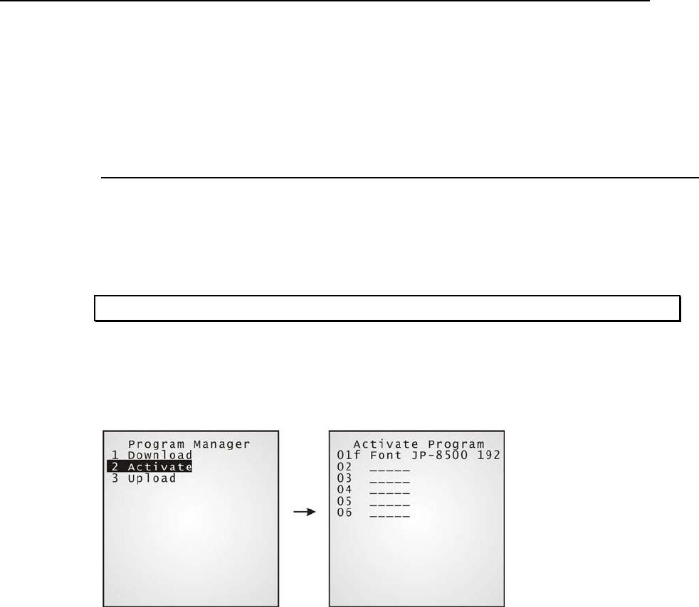
4.2.2 Activate
The list shows the entire spare programs stored in the terminal. From the list, you can select
from 01 to 06 and activate one of them.
¾ Activate an application program
The selected program will be copied to the active memory bank and replace the current one.
When <New Program Start> screen prompts “Press [ESC] to clear file”, it means the file
system in the SRAM will be cleared out by pressing [ESC]. Then there will be no data
(transactions, settings, etc.) stored in the terminal when the new program comes into effect.
To keep the data, simply press any other key.
¾ Activate a font file
The selected font file will be copied to the active memory bank and replace the current font
or system font. However, the active application program will remain intact.
74 Industrial CPT-8500 Reference Manual
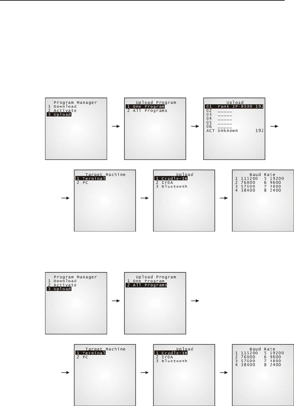
4.2.3 Upload
You may duplicate any program or all in the terminal to a host computer or another
terminal.
¾ One Program
The procedures are similar to those for loading programs.
¾ All Programs
The procedures are similar to those for loading programs.
Chapter 4 Configuring CPT-8500 75
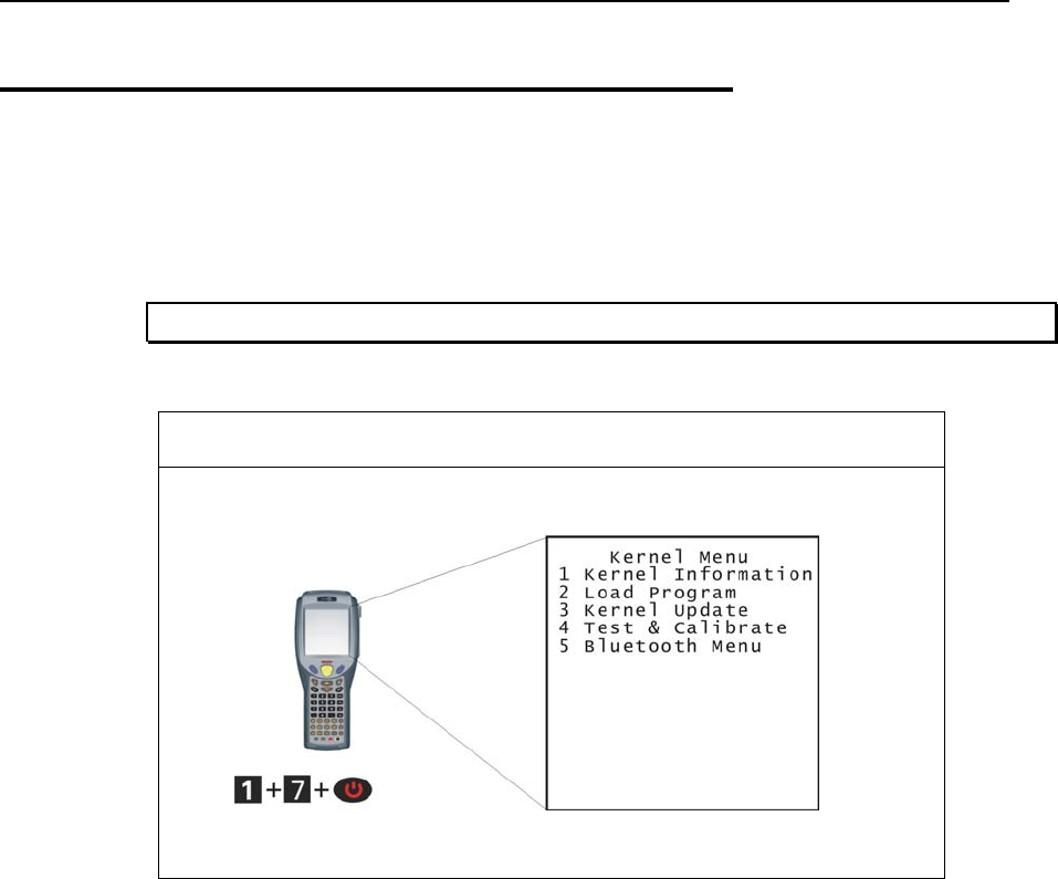
4.3 Kernel Menu
The Kernel Menu resides in the innermost core of the system. It has the highest security and
is always protected by the system. When the application program is corrupted and the
System Menu fails, the Kernel Menu provides an access to fix the system.
Warning! The Kernel Menu is NOT for the use of any end users.
How to access the Kernel Menu?
76 Industrial CPT-8500 Reference Manual
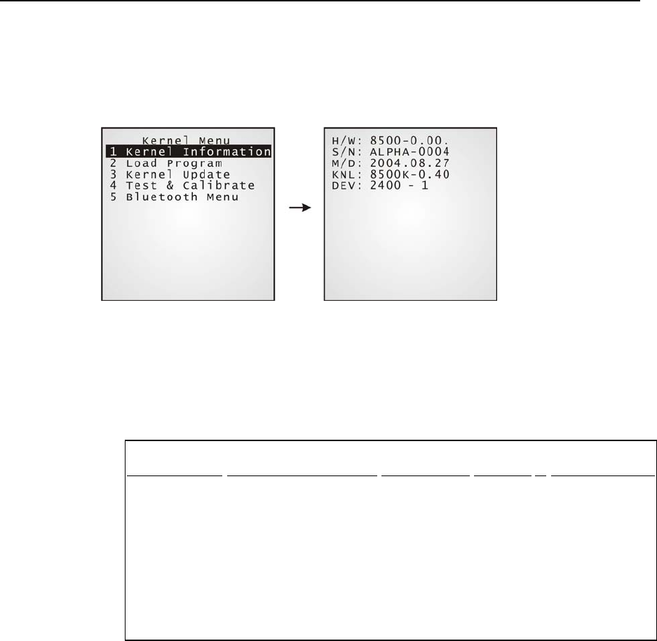
4.3.1 Kernel Information
The information provided here helps diagnose the system.
H/W: Hardware version (PCB)
S/N: Serial number of the terminal
M/D: Manufacturing date
KNL: Kernel version
DEV: Code for optional hardware configurations, i.e. 2400-1
2 4 0 0 - 1
Type of Reader
Type of Wireless Module
RFID Module
Reserved
Keyboard layout
0= none
1= CCD
2= Laser
3= 2D
0= none
3= GSM (+ Bluetooth)
4= 802.11b (+ Bluetooth)
5= Bluetooth only
7= GSM + 802.11b (+
Bluetooth)
0= none
1= RFID
0= 24-key
1= 44-key
Chapter 4 Configuring CPT-8500 77
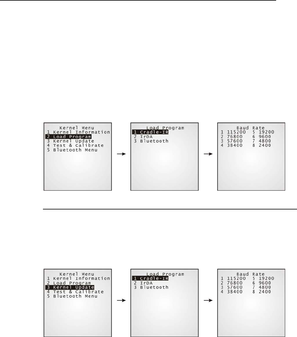
4.3.2 Load Program
Download program or font file to the active memory bank.
New application program
Program update
Font file, i.e. multi-language font
¾ Results
Success: the new program or font file will be activated right after downloading.
Failure: the terminal will resume to the current application program or system font.
Interface
Cradle-IR The communication parameters at PC end should be set accordingly.
IrDA Point to the target IrDA device.
Bluetooth Approach to the target Bluetooth enabled device.
4.3.3 Kernel Update
The Kernel might be changed for improving performance or other reasons, and, an update is
necessary.
The procedure is the same as that for downloading program.
78 Industrial CPT-8500 Reference Manual
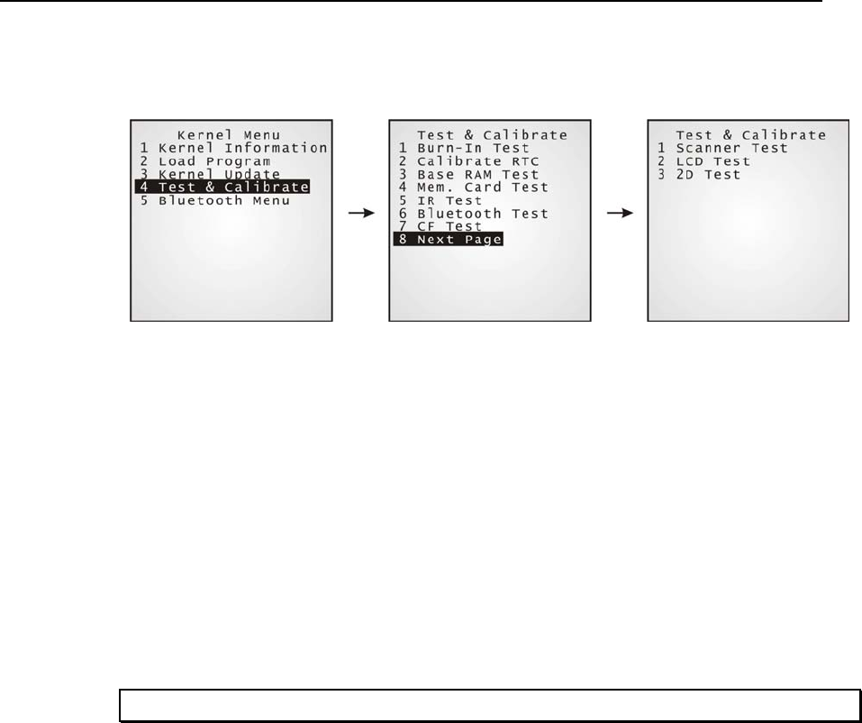
4.3.4 Test & Calibrate
These tools are provided for manufacturing use. No user definition is allowed.
Burn-In Test
Calibrate RTC
Base RAM Test
Memory Card Test
IR Test
Bluetooth Test
CF (CompactFlash) Test
Scanner Test
LCDTest
2D Test
Warning! This is NOT for the use of any end users.
Chapter 4 Configuring CPT-8500 79
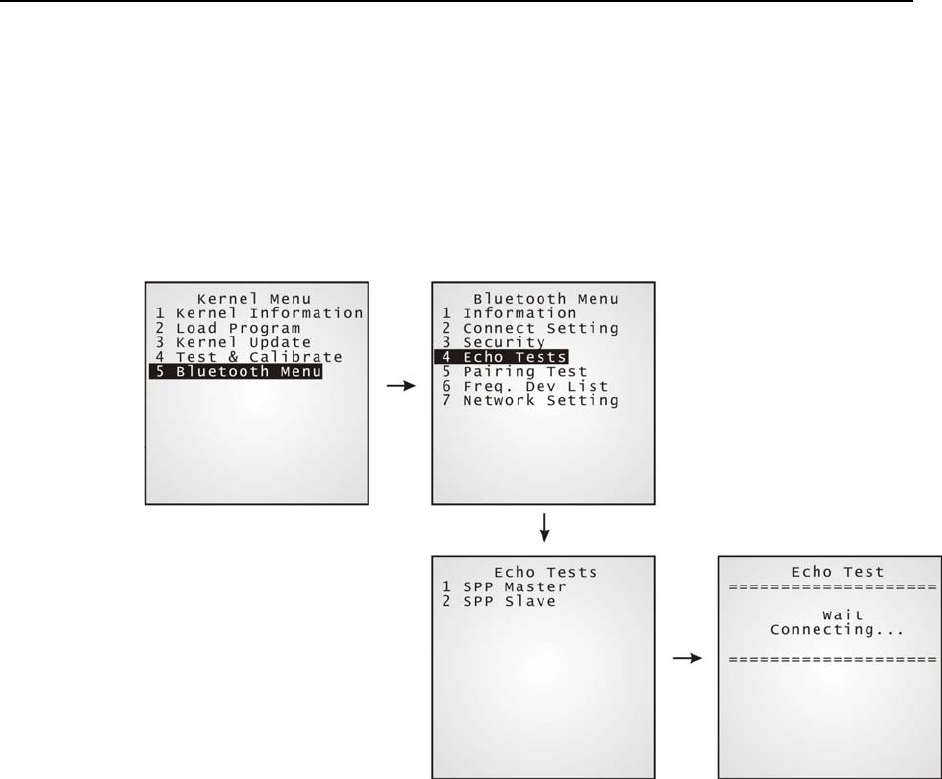
4.3.5 Bluetooth Menu
This submenu is the same as that under the System Menu except there is no Network Setting
here.
Moreover, the echo test for Bluetooth in Kernel mode is available for SPP (Serial Port
Profile) only.

80
Depending on the application program downloaded to the terminal, managing the
CPT-8500 terminal at PC end can be very flexible and simple.
Note: For details, please see relevant documents such as Programming Guide.
In This Chapter
5.1 For proprietary applications......................................... 80
5.2 For custom applications............................................... 80
5.1 For proprietary applications
For the preloaded application program (U8500*.SHX), we provide a PC development tool,
the Application Generator (AG8500*.exe), for creating application templates from PC end
in a time-saving way.
5.2 For custom applications
For user-defined application programs, software is to be developed by your own system
programmers.
¾ Programming Support
For development of custom application software, proprietary BASIC or C complier is
available through licensing agreement, as well as libraries.
CHAPTER 5
Managing CPT-8500

Specifications 81
Power
Main battery: Rechargeable 3.7 V, 4000 mAh Li-ion battery pack
Backup battery: Rechargeable 3.0 V, 7 mAh Lithium button cell
Working time: 500 hours
CPU
32-bit CPU: Toshiba CMOS type; 40 MHz
Memory
Flash: 2 MB program memory
SRAM: Standard 2 MB on-board data memory
Memory card (optional)
Programming Support
Proprietary Development Tool: Windows-based application generator (AG)
Compliers: BASIC, C
Emulation VT 100/200, IBM 5250
Environment
Humidity: Operating: 5% to 90% non-condensing
Storage: 5% to 95% non-condensing
Temperature: Operating: -20 to 60 °C
Storage: -30 to 70 °C
Shock Resistance: 2 m multiple drops onto concrete
Splash/Dust Resistance: IP 64
EMC Certified
FCC Class A
CE Class A
C-Tick Class A
Enclosure
Material: Rubber & ABS plastic
Specifications

82 Industrial CPT-8500 Reference Manual
Dimensions: 228 mm (L) x 89.5 mm (W) x 59.5 mm (H)
Weight: Approx. 450 g
Approx. 550 g (One battery pack included)
Input Devices
Reader: One scan engine (long range imager/laser scanner/2D scanner)
and/or the RFID reader
Keyboard: 24-key or 44-key layout
Rubber keys, LED backlit, programmable
Display
160 x 160 pixels, 3” FSTN, LED backlit, programmable
19 lines by 26 characters for small fonts
9 lines by 20 characters for large fonts
Graphic LCD:
Touch screen control & signature capture
Indicators
LED: One dual-color LED, programmable
Buzzer: Low power transducer type, 1 KHz to 4 KHz, programmable
Vibrator: 9000 ± 2000 RPM, Max. 50 dB, programmable
Interfaces
Standard IrDA: Peer-to-Peer connection through IrDA ports
Bluetooth: Built-in WPAN networking, class 2
IEEE 802.11b: WLAN networking (optional)
GSM/GPRS WWAN networking (optional)
Note: All specifications are subject to change without prior notice.

Troubleshooting 83
The terminal does not power on when POWER key being pressed…
9 Make sure the battery pack is installed properly.
9 Re-charge the battery inside the terminal and monitor the charging status. (see 4.1.5)
9 If the battery is faulty, replace it with a fresh and fully charged battery then.
9 Only use the original battery or charging device for the CipherLab product line. The use of
wrong battery or charging device could result in damage to human body or the product itself,
and will void your warranty.
Charging error…
9 Make sure the power cord is well connected between the cradle/charger and an outlet.
9 Check if the battery contacts of the battery itself and the battery compartment are clean.
9 Try to re-charge the battery and monitor the charging status.
9 Only use the original battery or charging device for the CipherLab product line. The use of
wrong battery or charging device could result in damage to human body or the product itself,
and will void your warranty.
The keyboard input seems not working properly…
9 Perform the keyboard test. (see 4.1.3)
9 If the problem persists, slide the battery latch to reload the battery pack. Then perform the test
again.
The reader does not scan…
Low battery -
9 Check if the battery icon on the screen indicates a low battery status. If so, replace it with a
fresh battery then.
9 If the problem persists, check if the battery pack is well seated inside the terminal.
Regarding the reader -
9 Perform the reader test to see if the reader is working. (see 4.1.3)
9 If the problem persists, slide the battery latch to reload the battery pack. Then perform the test
again.
Troubleshooting

84 Industrial CPT-8500 Reference Manual
The reader does not decode after scanning…
Unreadable barcode -
9 Check if the barcode is defaced. A defaced barcode may not be readable.
Un-programmed to read -
9 Check if the scanner is programmed to read the symbologies (types of barcode) that you are
trying to read.
9 Try scanning a test barcode of the symbology you are trying to read.
Dirty scan window-
9 Check if the barcode is defaced. A defaced barcode may not be readable.
Out of scanning range -
9 Try adjusting the scanning distance from the scanner to the barcode.
The terminal cannot transmit/receive data to/from a host computer or other devices…
Over IrDA port -
9 Make sure the terminal's infrared port is pointed directly to the infrared port of another IrDA
device. The distance between the terminal and a target device is within proper range, and no
obstacles in between. Try to establish connection again.
Via Bluetooth -
9 Make sure the distance between the terminal and a target device is within proper range. Try to
establish connection again.
9 Check if the relevant settings are correct. (see 4.1.7)
9 Check if the connection is working properly. (see 4.1.7)
Over RS-232 port via Cradle -
9 Check if the RS-232 connection is correct and secured.
9 Make sure the serial port parameters on the host are configured to match the serial parameters
on the terminal. Try to establish connection again.
9 Make sure the terminal is well seated inside the cradle. DO NOT remove the terminal or
disconnect the cradle before communications are done.
9 If the problem persists, run the IR Echo Test to check the IR interface between the terminal and
the cradle. (see 4.1.3)

Troubleshooting 85
Over MODEM port via Cradle -
9 Check if the modem connection is correct and secured.
9 Make sure the modem parameters are configured to match the parameters on the terminal. Try
to establish connection again.
9 Make sure the terminal is well seated inside the cradle. DO NOT remove the terminal or
disconnect the cradle before communications are done.
9 If the problem persists, run the IR Echo Test to check the IR interface between the terminal and
the cradle. (see 4.1.3)
About abnormal response…
The LED or LCD seem not working properly -
9 Perform the LCD & LED test. (see 4.1.3)
9 If the problem persists, reload the battery pack and perform the test again.
The buzzer seems not working properly -
9 Perform the buzzer test. (see 4.1.3)
9 If the problem persists, reload the battery pack and perform the test again.
The terminal seems not working properly -
9 First upload all data to a computer, and then perform the memory test. (see 4.1.3)
9 If the problem persists, reload the battery pack and perform the test again.
The touch screen seems not working properly -
9 Perform the touch screen test. (see 4.1.3)
9 If the problem persists, reload the battery pack and perform the test again.
The vibrator seems not working properly -
9 Perform the vibrator test. (see 4.1.3)
9 If the problem persists, reload the battery pack and perform the test again.
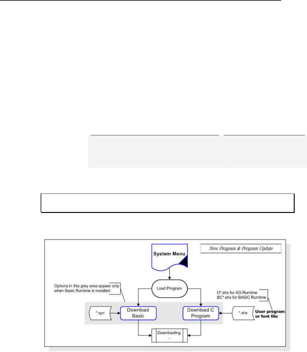
86 Industrial CPT-8500 Reference Manual
These utilities are for downloading any user program (*.shx or *.syn) to the terminal.
*.SHX: Any C program, such as AG runtime, Basic runtime or font file.
*.SYN: Any Basic program based on Basic runtime installed first.
Currently, the ProgLoad.exe has replaced several previously released utilities.
has replaced the following utilities: File type:
Download. exe *.SHX
IRLoad.exe *.SHX
SynLoad.exe *.SYN
TcpLoad.exe *.SHX
ProgLoad.exe
TcpSynLoad.exe *.SYN
Note: Both TcpLoad.exe and TcpSynLoad.exe are not for portable terminals. They are for
the use of stationary terminals.
¾ Downloading in System mode
Appendix I - Download Utilities

Appendix I - Download Utilities 87
¾ Downloading in Kernel mode
Figure 17: Downloading in Kernel mode
¾ Downloading in Program Manager mode
Figure 18: Downloading in Program Manager mode
ProgLoad, all-in-one interface
File name: ProgLoad.exe
It supports all file types and communications interfaces.
Communications Interface:
RS-232 / IrDA Connection via direct RS-232 cable or IrDA port
Serial IR Connection via serial cradle
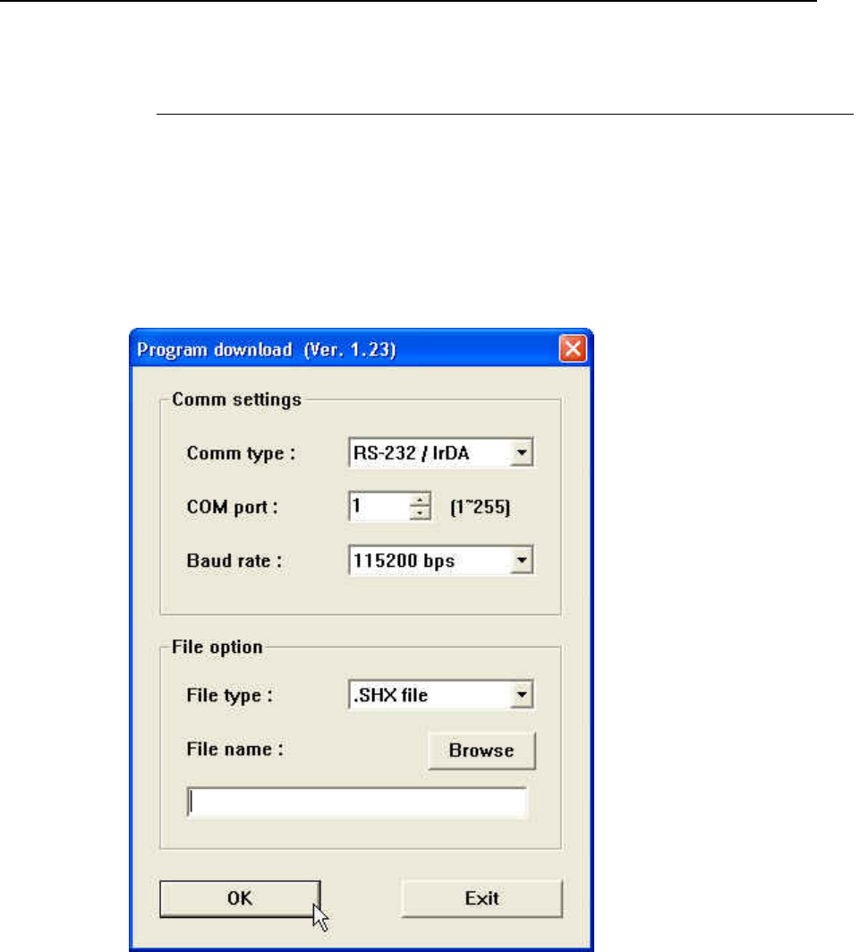
88 Industrial CPT-8500 Reference Manual
TCP/IP Connection via networks
File Type:
*.SHX Any C program, such as AG runtime, Basic runtime or font file
*.SYN Any Basic program based on Basic runtime installed first
¾ Selection Menu
Step 1: Execute program. The following menu pops up.
Step 2: Select interface, file and COM port properties from the menu.
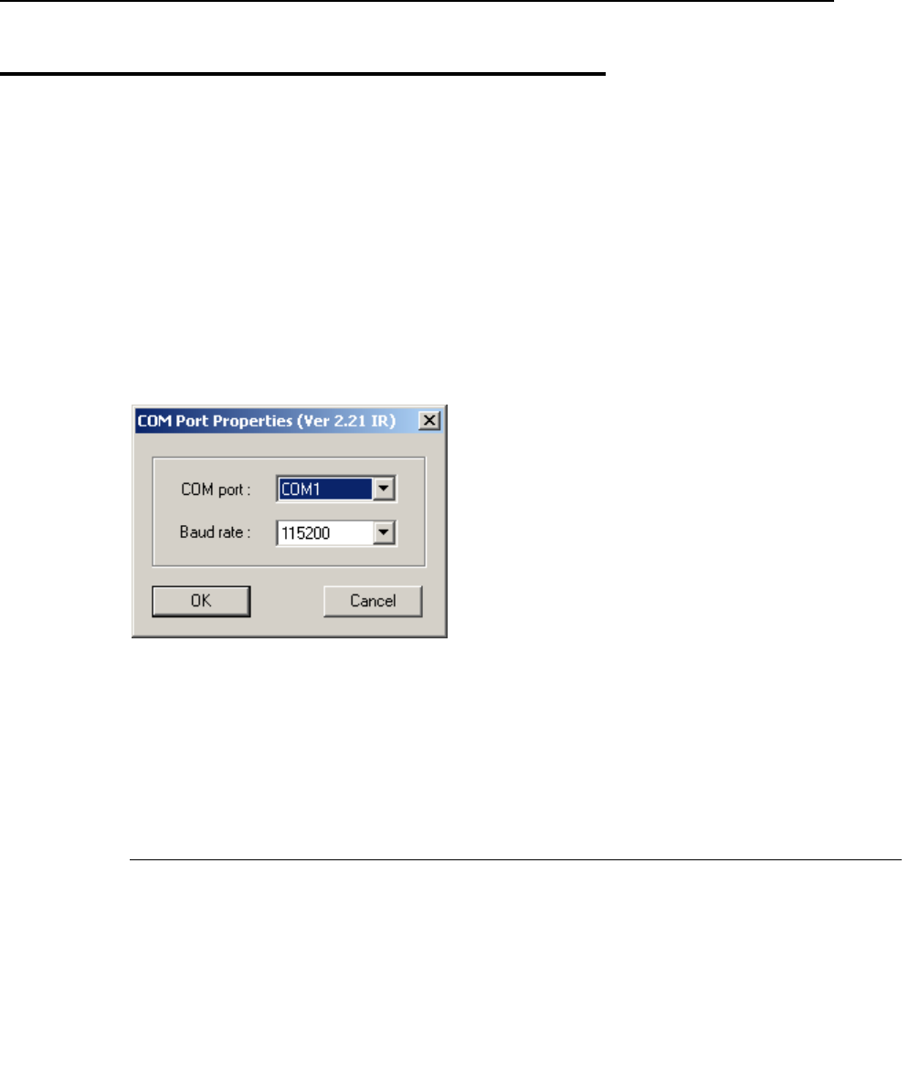
Appendix I - Download Utilities 89
IRLoad, Cradle-IR interface
File name: IRLoad.exe
It supports command line arguments.
¾ Selection Menu
Step 1: Execute program.
Step 2: Choose file.
Step 3: Set the following COM port properties.
¾ Command Line
IRLOAD U8300-114.SHX,2,1//COM2,115200 bps
If command line arguments are not given, the user can select appropriate parameters from
the pop-up dialog box.
IRLOAD [filename],[COM port],[Baud rate]
File name: The file name of the program that is to be downloaded.
COM port: 1 ~ 8 Default: 1
Baud rate: 1 ~ 5 1 for 115200 bps
2 for 57600 bps
3 for 38400 bps
4 for 19200 bps
5 for 9600 bps
Default: 1
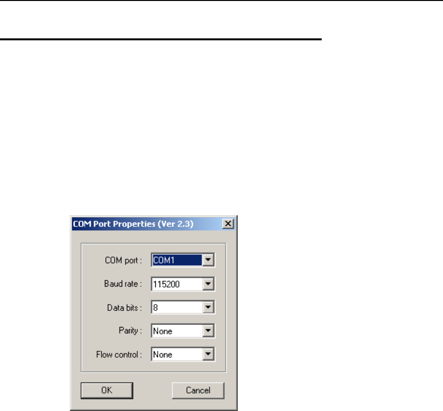
90 Industrial CPT-8500 Reference Manual
Download, RS-232 or IrDA interface
File name: Download.exe
It supports command line arguments.
¾ Selection Menu
Step 1: Execute program.
Step 2: Choose file.
Step 3: Set the following COM port properties.
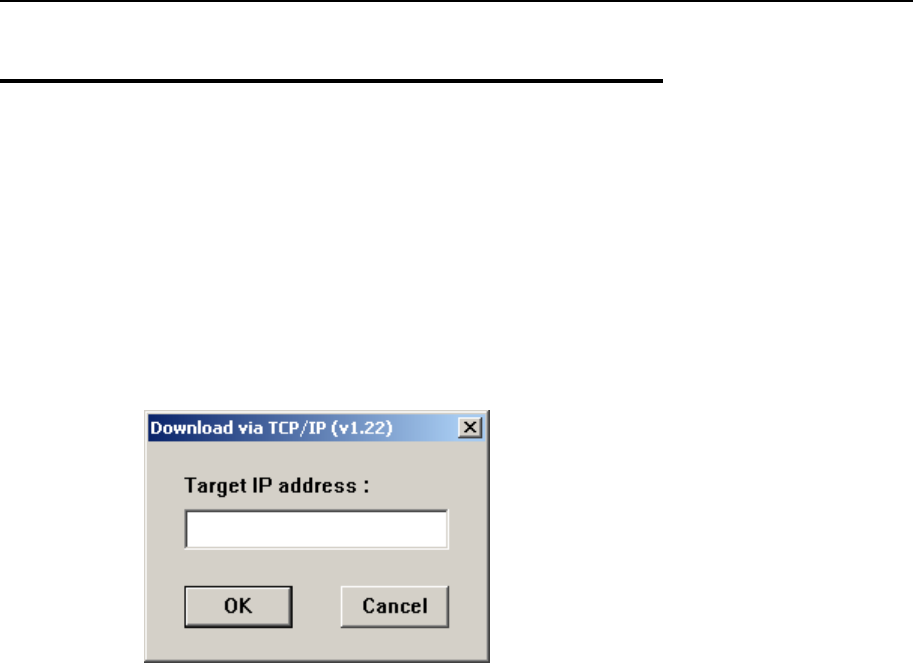
Appendix I - Download Utilities 91
TcpLoad, IP interface
File name: TcpLoad.exe
¾ Selection Menu
Step 1: Execute program.
Step 2: Choose file.
Step 3: Set target IP address as follows.

92
A
Access Point • 17, 18, 59
Activate • 73
Ad-hoc • 17, 18, 64
AG Runtime • 35
Application Generator (AG) • 35, 80
Authentication • 54, 66
Auto Off • 41
B
Backlight • 13, 41
Battery • 22, 23
Backup • 7
Low • 8
Main • 7
Bluetooth • 15, 17, 33
Menu • 50, 79
BNEP • 17, 55, 57
Broadcast • 52
BSC • 39, 51
Buzzer • 13, 46
C
Calendar • 8
Calibrate • 78
Calibration • 43
Charging • 23, 31
Initial • 7
Status • 29
Client Mode • 57, 68
Communications • 23, 31
Status • 29
Wired • 32
Wireless • 33
CPU • 8
Cradle • 22, 26, 28, 31, 33
CTY • 51
D
Data Loss • 9
DEV • 39, 76
Development Tools • 20, 80
DHCP • 51, 60, 63
Dial Out • 55, 56
DIP Switch • 30, 33
DNS • 60, 63
Domain • 60, 63, 64
Download • 49, 71, 77, 86
Dual Mode • 14
DUN • 17, 55, 56, 58, 59
E
EAP • 67
Echo • 55, 68, 79
IR • 46
F
Font • 12, 43, 49, 71, 77
Frequent Device List • 59
FSTN • 12
G
Gang Charger • 31
Gateway • 51, 60, 63
GSM/GPRS • 15, 19, 33
H
Hand Strap • 22, 24
I
IAM • 51
IEEE 802.11b • 15, 18, 33
Menu • 62
Infrastructure • 18, 64
Ingress Protection (IP) • 20
IrDA • 15, 16, 33
K
Kernel Menu • 36, 75
Keyboard • 9, 46
Key Click • 42
Layout • 10, 11
KNL • 39, 76
Index

Index 93
L
LCD • 12, 46
LED • 13, 46
LIB • 39, 51
Local IP • 51, 60, 63
Local Name • 52, 64
M
MAC • 51, 63
Master Mode • 56
Memory • 8, 46, 47
Module
Kernel • 36
Program • 35
System • 36
P
Pairing • 58
PAN • 17, 55, 57, 58, 59
Piconet • 52
PIN • 54
Pistol Grip • 22, 25
Power • 7, 48
Power On • 41
Power Saving • 52, 64
Preamble • 64
Program Manager Menu • 36, 70
R
Reader • 45
2D Scanner • 14
Laser Scanner • 14
Long Range Imager • 14
RFID Reader • 14
Real Time Clock (RTC) • 7, 40
Remote Name • 52
Reset • 44
Resistance
Shock • 20
Splash & Dust • 20
RFID • 14, 46
S
Screen Icons • 9
Server Mode • 57, 69
Signature Capture • 13
Slave Mode • 56
SPP • 17, 55, 56, 58, 59, 79
SS ID • 64
Subnet Mask • 51, 60, 63
System Menu • 36, 38
System Password • 42
System Scale • 64
T
Terminal Emulation • 20
Tests • 45, 46, 55, 68, 78
Touch Screen • 13, 43, 46
U
Update • 49, 77
Upload • 74
USR • 39
V
Vibrator • 13, 46
W
WEP • 67
Wireless • 15
WLAN • 18, 64
WPAN • 17
WWAN • 19