CipherLab 85002 Terminal User Manual 8500 Manual
CipherLab Co., Ltd. Terminal 8500 Manual
UserManual.wiki
>
CipherLab
>
85002 User Manual
Manual
Navigation menu
Upload a User Manual
Namespaces
Wiki Guide
HTML
PDF
Info
Views
User Manual
Discussion / Help
Navigation

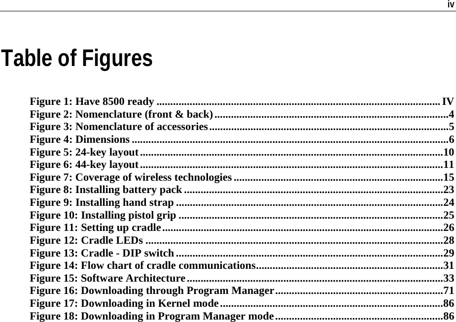
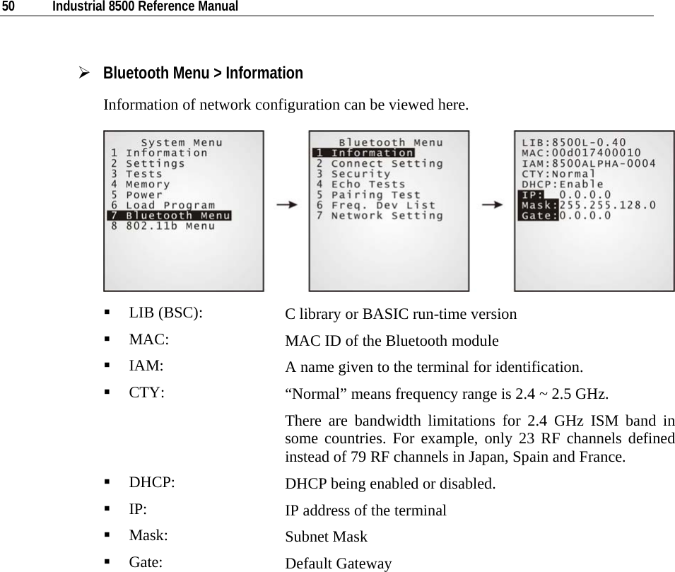
![Chapter 1 Introducing 8500 9 ¾ Caution of Data Loss When the main battery is removed or drained, the backup battery on the main board is to retain the contents of SRAM and maintain the running of the calendar for at least one week, on condition that the backup battery has already been fully charged. If the terminal is to be put away for a couple of days, you should be aware that data loss occurs when both the main and backup batteries discharge completely. Therefore, it is necessary to save data in a host computer before putting away the terminal. Note: Being fully charged, the backup battery can last at least 1 week. 1.3.4 Keypad The terminal is equipped with a keypad of either 24 keys or 44 keys, which has programmable LED backlight, for system setup, user entry and so on. Silicon rubber has been chosen for their durability and prompt feedback. The key click can be configured through the System Menu. Note: Functionality of keys is application-dependent. ¾ Screen Icons The following icons appear on the screen when a certain mode is activated, that is, holding down the specific key is unnecessary. Simply press another key or red-coded function key ([F1] ~ [F12]) to produce a result. 24-key A / a: : Press [Alpha] to enter the alphabetic mode, capital or small letters. Press [FN] to enter the function mode (user definable). 44-key : : : Press [Shift] to enter the special function mode (user definable). Press [RED] to enter the function mode (user definable). Press [Alt] to enter the special function mode (user definable).](https://usermanual.wiki/CipherLab/85002/User-Guide-823769-Page-18.png)
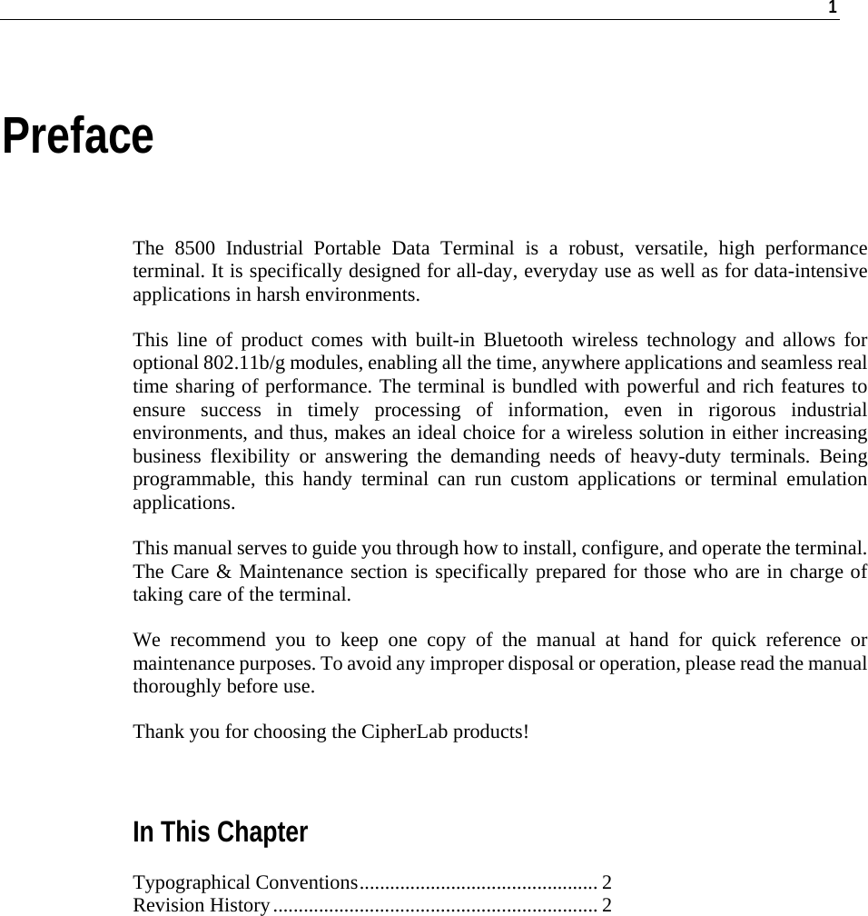
![10 Industrial 8500 Reference Manual 24-key layout The layout of the 24-key keypad is similar to that of a telephone, which consists of an alphanumeric keypad, numbers and assorted characters. This keypad is set to numeric mode by default. For alpha mode, simply press [ALPHA] to toggle between alpha and numeric modes. Figure 5: 24-key layout](https://usermanual.wiki/CipherLab/85002/User-Guide-823769-Page-19.png)
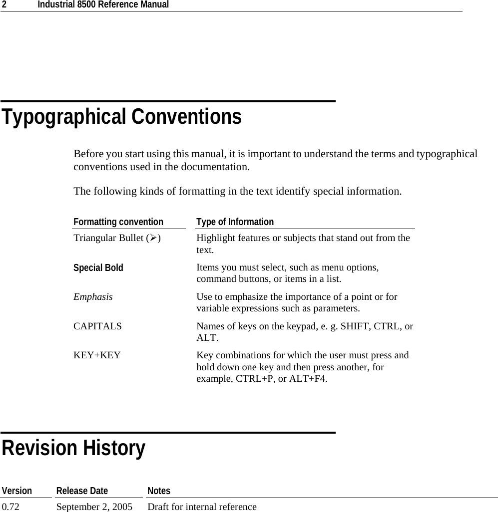
![Chapter 1 Introducing 8500 11 44-key layout The layout of the 44-key keypad includes numeric, alphabetic, assorted characters, function and modifier keys. Figure 6: 44-key layout For the 44-key keypad, these keys can be categorized into the following groups by color: Blue Area: 9 Two [Enter] keys: user-friendly and convenient for either right-handed or left-handed operator to perform general function of a [Enter] key. 9 It can be used together with [RED] modifier key: [Enter] + [RED] = alternately turn ON/OFF the backlight of LCD and keypad.](https://usermanual.wiki/CipherLab/85002/User-Guide-823769-Page-20.png)
![12 Industrial CPT-8500 Reference Manual Black Area: 9 Power key 9 Numeric keys 9 Modifier keys: [Shift] or [Alt] that modifies its next key. The functionality depends on software application. 9 Others like [Backspace], [ESC], [Space], [Tab], [Insert], [Delete], [ - ], [ . ] Yellow Area: 9 [Scan] button 9 Navigation keys for moving the cursor up, down, left, right. 9 Alphabetic keys 9 Others like punctuation keys for comma & semi-colon, dollar & colon. Red Area: 9 [RED] modifier key: the solid red key next to the Power key 9 [RED] followed by one red-coded key: The [RED] modifier key modifies (activates) the second key. Its functionality is determined by the red-coded key, which is specified by red letters under the navigation keys or on top of alpha keys and some punctuation keys. 1.3.5 LCD The terminal comes with a 3” FSTN graphic LCD, 160 by 160 pixels resolutions, which can be configured to display text or graphics, such as specific font and company logo, to meet varying application needs. English Font: Small fonts (6×8 pixels) Large fonts (8×16 pixels) 21 by 8 lines 16 by 4 lines Chinese Font: (16×16 pixels) 8 by 4 lines Other language fonts, company logo… Programmable](https://usermanual.wiki/CipherLab/85002/User-Guide-823769-Page-21.png)
![Chapter 1 Introducing 8500 13 ¾ Backlight Setting The LED backlight of screen and keypad helps ease reading under dim environments. It can be alternately toggled ON and OFF by simultaneously pressing the following keys: 24-key: [Enter] + [FN] 44-key: [Enter] + [RED] ¾ Touch Screen & Signature Capture This LCD is also a touch screen, which enables the use of a stylus for handwriting. It also features signature capture that can save signature as confirmation of receipt when delivering goods to door. The screen can be calibrated by tool provided in the System Menu. Warning! DO NOT use any pointed or sharp objects to move against the surface of the screen. 1.3.6 Status LED The dual-color LED on top of the [Scan] button is to provide information on status of scanning. It is programmable for diagnostics and application dependant. Red LED - Error Green LED - Good Read 1.3.7 Buzzer The buzzer, a low power transducer type, can be programmed for status feedback. Its pitch and duration are software programmable. 1.3.8 Vibrator Like a modern mobile phone, the terminal is integrated with a vibrator. It is software programmable and especially useful when working in a noisy environment.](https://usermanual.wiki/CipherLab/85002/User-Guide-823769-Page-22.png)
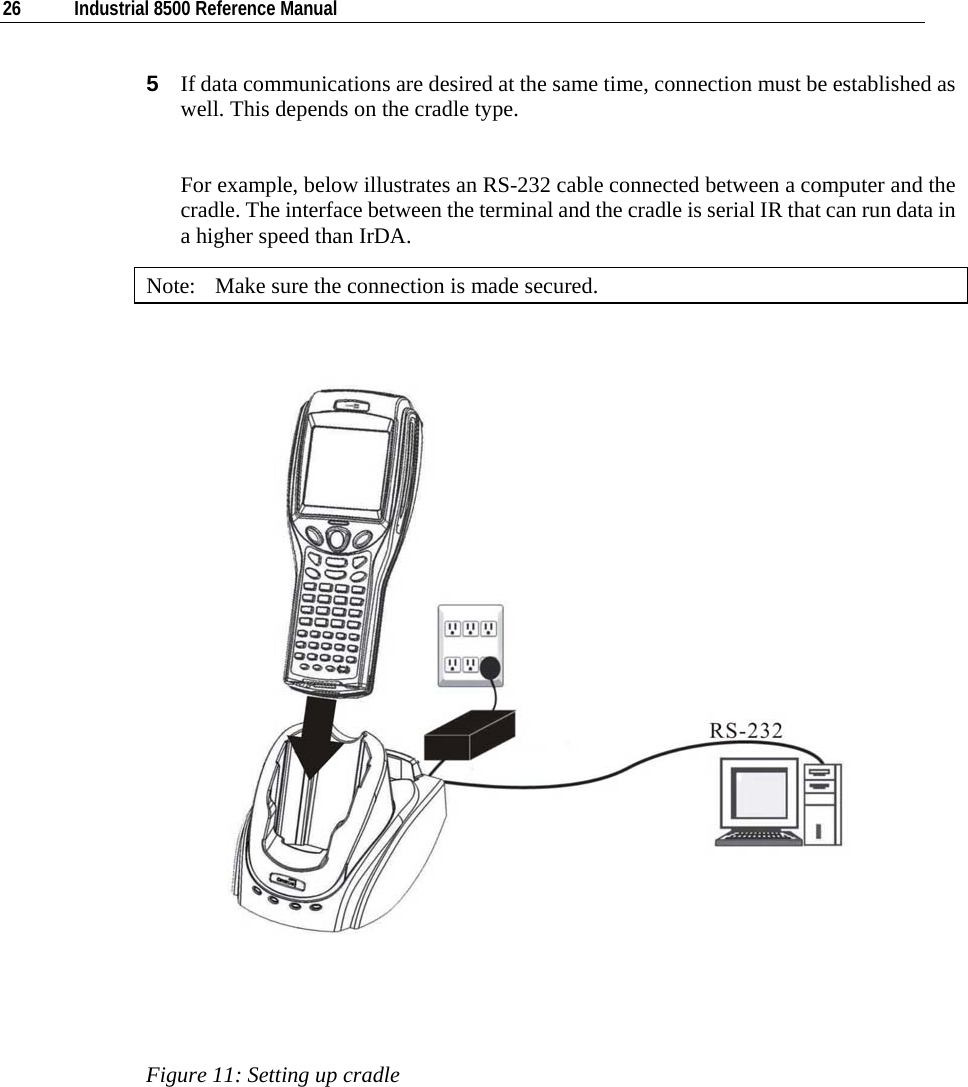
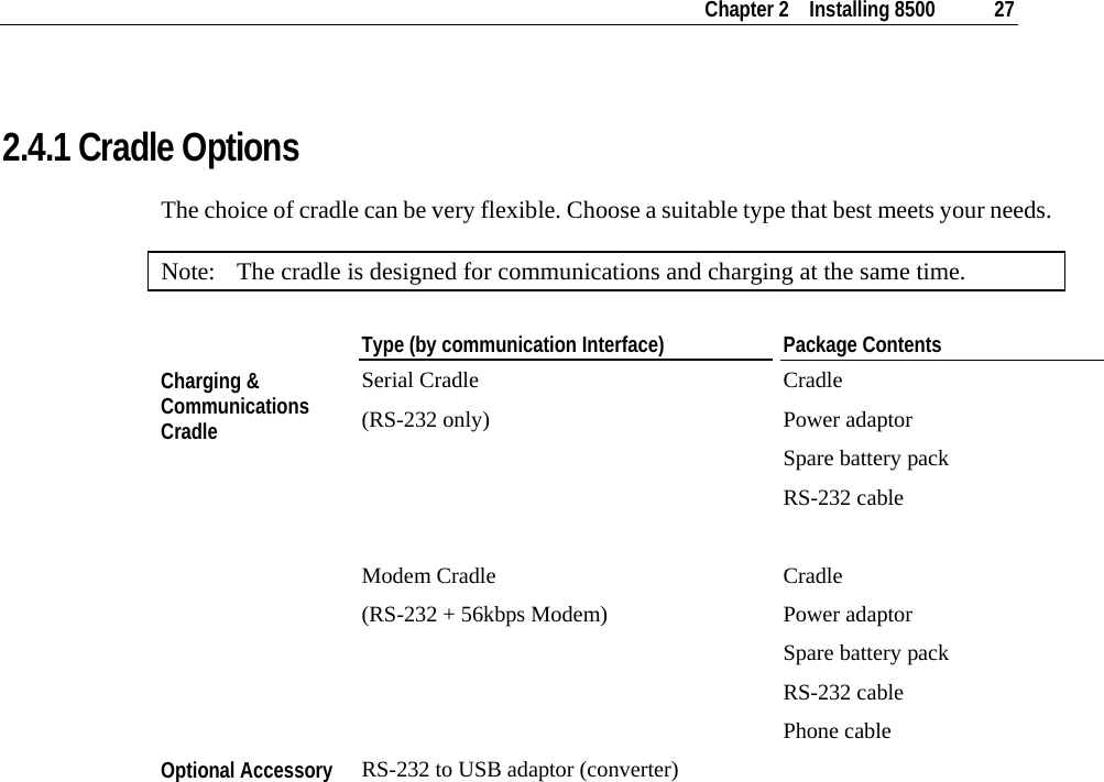
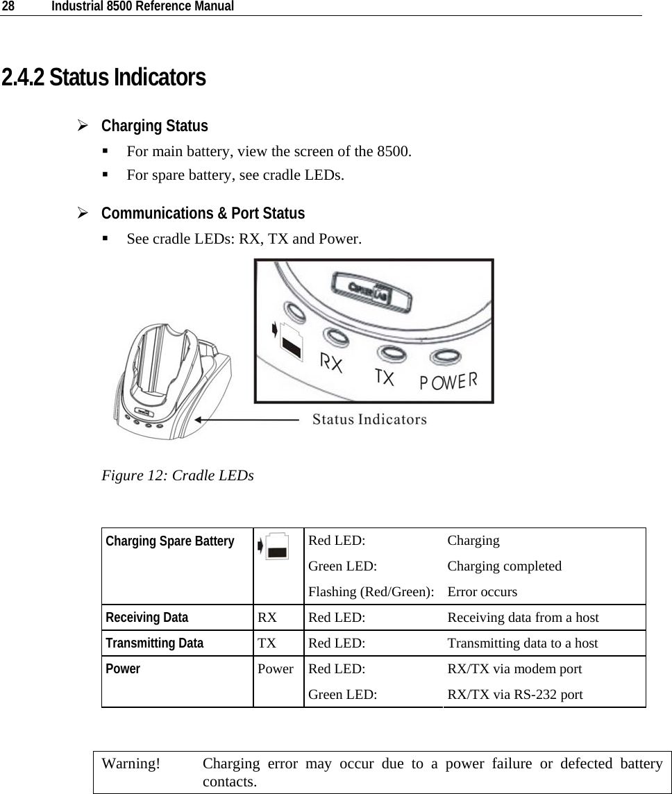
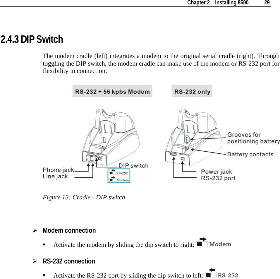
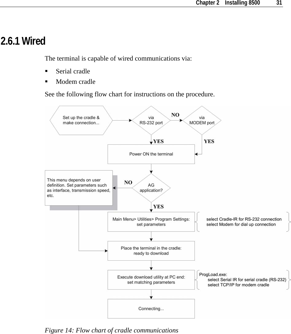
![32 Industrial 8500 Reference Manual ¾ Serial Cradle (RS-232) When the cradle is set up, 1 Connect one end of a RS-232 cable to the RS-232 port on the back of the cradle. 2 Connect the other end of the cable to the RS-232 port of a host computer. 3 See the flow chart for the rest steps. ¾ Modem Cradle When the cradle is set up, 1 For communications via an internal modem, slide the DIP switch on the back of the cradle to right. 2 Connect the telephone line to the [Line] jack on the back of the cradle. 3 You may connect the cradle to a telephone through the [Phone] jack. 4 See the flow chart for the rest steps. 2.6.2 Wireless The terminal is capable of wireless communications via the following technologies: IrDA Bluetooth IEEE 802.11b/g Refer to 1.3.10 Wireless Support for more details.](https://usermanual.wiki/CipherLab/85002/User-Guide-823769-Page-41.png)
![40 Industrial 8500 Reference Manual ¾ Settings > Backlight Period Set the backlight duration for the keypad and LCD. Enter a value between 0 and 9999. ¾ Settings > Auto Off Set time threshold for the terminal to automatically power off when no operation is taking place during that specific period. Enter a value between 0 and 999. Note: To disable this function, enter 0. ¾ Settings > Power On Options Set the startup screen right after powering on: [0] Program Resume: Start from the last session of program before shutdown. [1] Program Restart: Fresh start from the first session of the program.](https://usermanual.wiki/CipherLab/85002/User-Guide-823769-Page-49.png)
![42 Industrial 8500 Reference Manual ¾ Settings > Font Current font information can be viewed here. Default: System font Custom font file, if there is one The font settings here can be changed if a "multi-language" font file has been downloaded. (Press [Up] or [Down] to move the cursor up or down through the menu of options.) ¾ Settings > Screen Calibration The cross mark will appear on the four corners of the screen for alignment. Use the tip of the stylus to tap at the center of the cross mark firmly and accurately. Warning: DO NOT use any pointed or sharp object to move against the screen.](https://usermanual.wiki/CipherLab/85002/User-Guide-823769-Page-51.png)
![44 Industrial 8500 Reference Manual 4.1.3 Tests Here provides functional tests for key parts. ¾ Tests > Reader Test the reading performance of the scanner, with laser or image scanning engine. Press [SCAN] to start. To stop and exit the test, press any key. The following barcodes are enabled by default: Code 39 Industrial 25 Interleave 25 Codabar Code 93 Code 128 UPCE UPCE with ADDON 2 UPCE with ADDON 5 EAN8 EAN8 with ADDON 2 EAN8 with ADDON 5 EAN13 EAN13 with ADDON 2 EAN13 with ADDON 5 … Other barcodes must be enabled through programming.](https://usermanual.wiki/CipherLab/85002/User-Guide-823769-Page-53.png)
![Chapter 4 Configuring 8500 45 ¾ Tests > Buzzer Test the buzzer with different frequency/duration combinations. Press [Enter] to start. Press any key to stop and exit the test. ¾ Tests > LCD & LED Test the LCD display and LED indicator. Press [Enter] to start. Press any key to stop and exit the test. ¾ Tests > Keyboard Test the rubber keys. Press any key and its corresponding character will be shown on the screen. Press [ESC] to stop and exit the test. ¾ Tests > Memory Test the data memory (SRAM), and the results will be shown on the screen. Press any key to exit. Warning! The contents of the data memory (SRAM) will be wiped out after test. ¾ Tests > Touch Screen Test signature capture by using the stylus for handwriting. Press [Enter] to start. Press [ESC] to stop and exit the test. ¾ Tests > RFID Test the reading performance of the RFID reader when a proximity card is present. Press [ESC] to stop and exit the test. ¾ Tests > Vibrator Test the vibrator. Press [ESC] to stop and exit the test. ¾ Tests > IR Echo Test The echo test is to verify connectivity between the terminal and the cradle (serial IR). Run the echo test at baud rate 38400. Press [ESC] to stop and exit the test.](https://usermanual.wiki/CipherLab/85002/User-Guide-823769-Page-54.png)
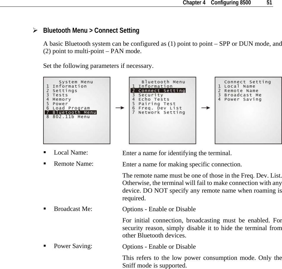
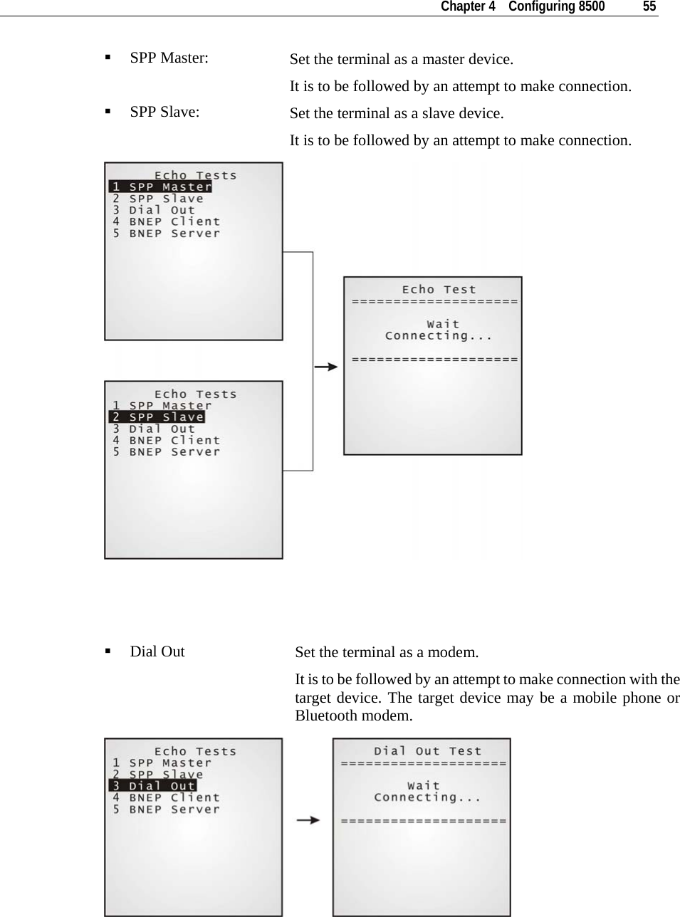
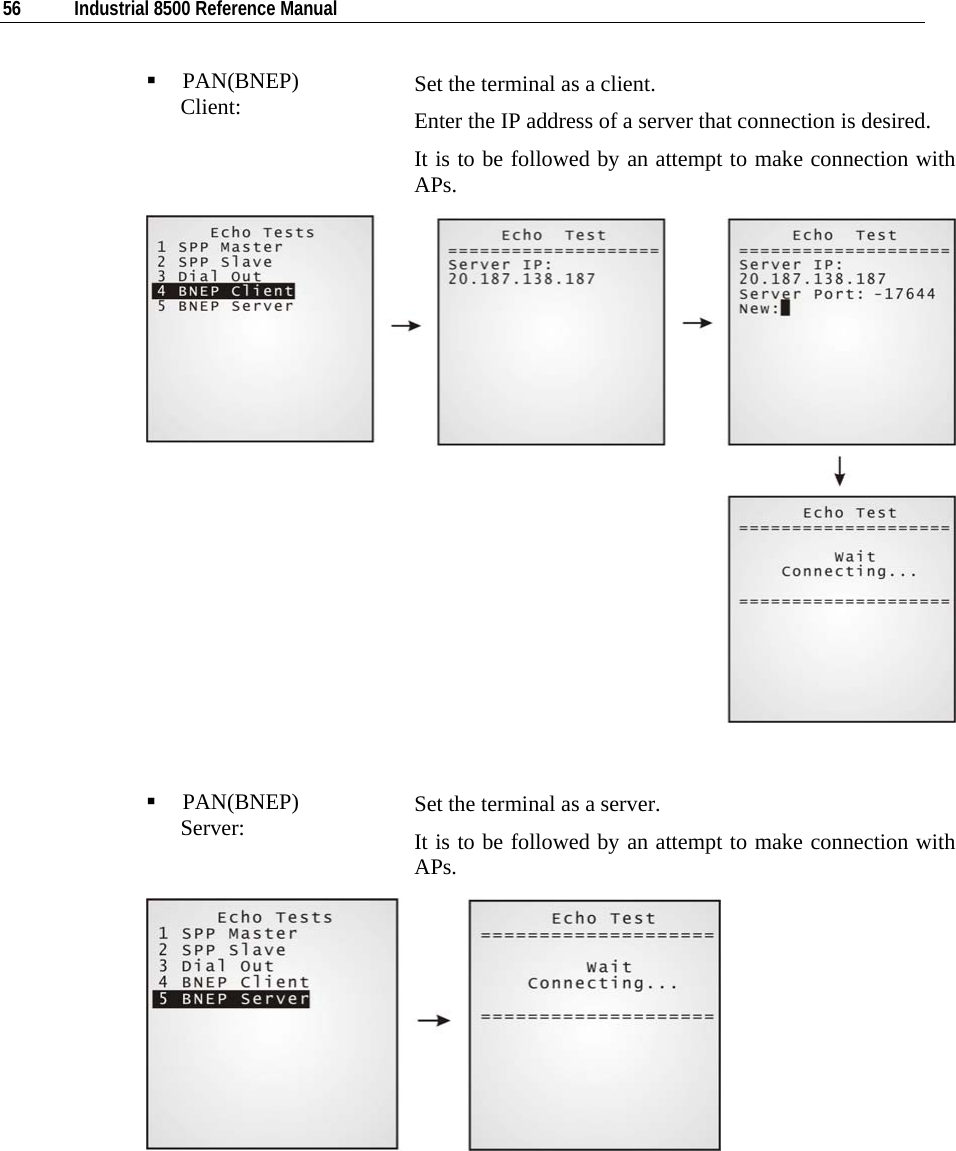
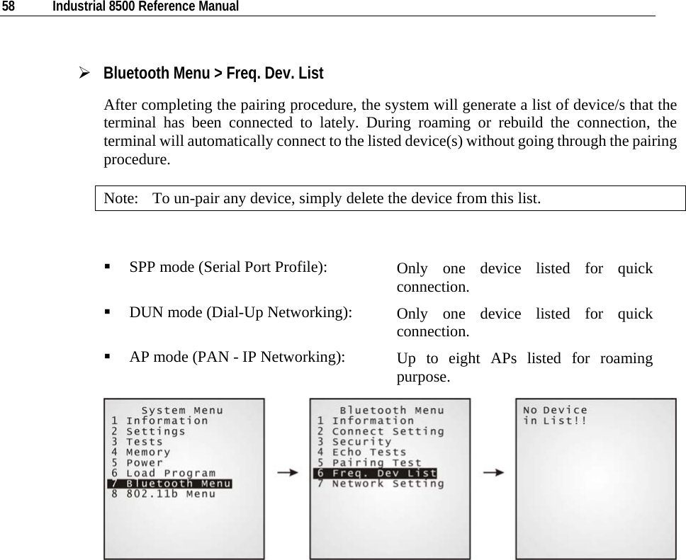
![54 Industrial 8500 Reference Manual ¾ Bluetooth Menu > Echo Tests Echo tests are used for verifying connectivity to make sure the terminal is within coverage. Press [ESC] to stop and exit the test. For PAN mode, it helps estimate the number of APs and terminals, and determine the topology of deploying APs. “SPP”: Serial Port Profile - for ad hoc networking, without going through any access point. “Dial Out”: For Dial-Up Networking Profile, also known as DUN. It makes use of a Bluetooth modem or mobile phone as a wireless modem. “PAN(BNEP)”: Personal Area Networking Profile - uses Bluetooth Network Encapsulation Protocol for IP networking over Bluetooth. Note: You also need a test utility on PC to test the networking.](https://usermanual.wiki/CipherLab/85002/User-Guide-823769-Page-63.png)
![Chapter 4 Configuring 8500 57 ¾ Bluetooth Menu > Pairing Test The pairing procedure is for the creation and exchange of a link key between two Bluetooth-enabled devices. The devices use the link key for future authentication when exchanging information. After inquiry, there will be a “Target Machine” menu for selecting mode: Serial Port (SPP) Access Point (PAN) Dial Up Network (DUN) Press [ESC] to stop and exit the test. Note: During the initial setting of Bluetooth wireless network, the pairing procedure must be carried out before the Echo tests.](https://usermanual.wiki/CipherLab/85002/User-Guide-823769-Page-66.png)
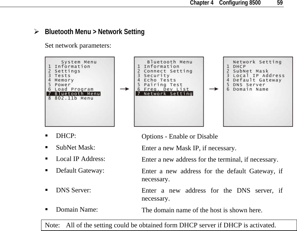
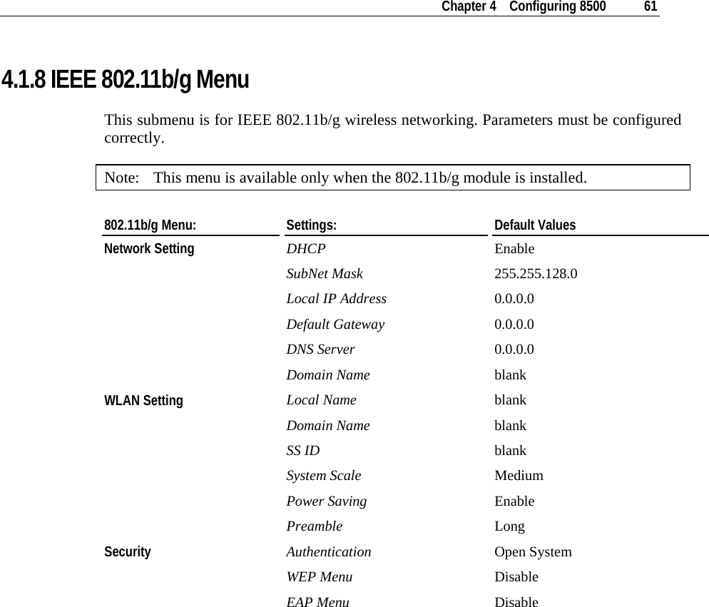
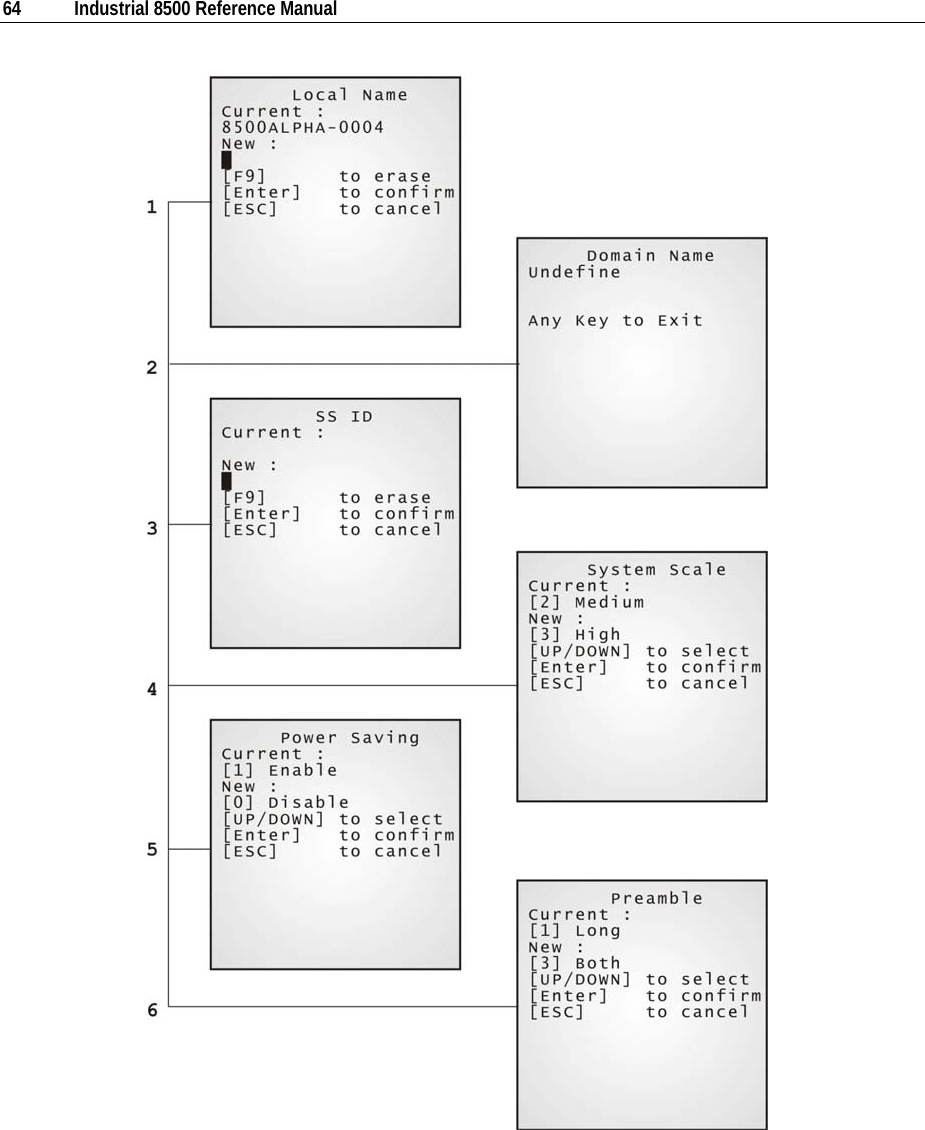
![Chapter 4 Configuring 8500 63 ¾ 802.11b/g Menu > WLAN Setting 802.11b/g system can operate in two modes (1) Ad-hoc mode: peer-to-peer, and (2) Infrastructure mode: point to multi-point through access points. Set the following parameters. Local Name: Enter a name for identifying the terminal. Domain Name: The domain name of the host is shown here. SS ID: This refers to Service Set ID or Identifier. The terminal can ONLY communicate with access points that have the same SS ID System Scale: This refers to Access Point Density. Options - [1] Low [2] Medium [3] High The value you set must match that set for the access point. Power Saving: This refers to the low power consumption mode. Options - Enable or Disable The value you set must match that set for the access point. Preamble: Options - [1] Long [2] Short [3] Both The value you set must match that set for the access point.](https://usermanual.wiki/CipherLab/85002/User-Guide-823769-Page-72.png)
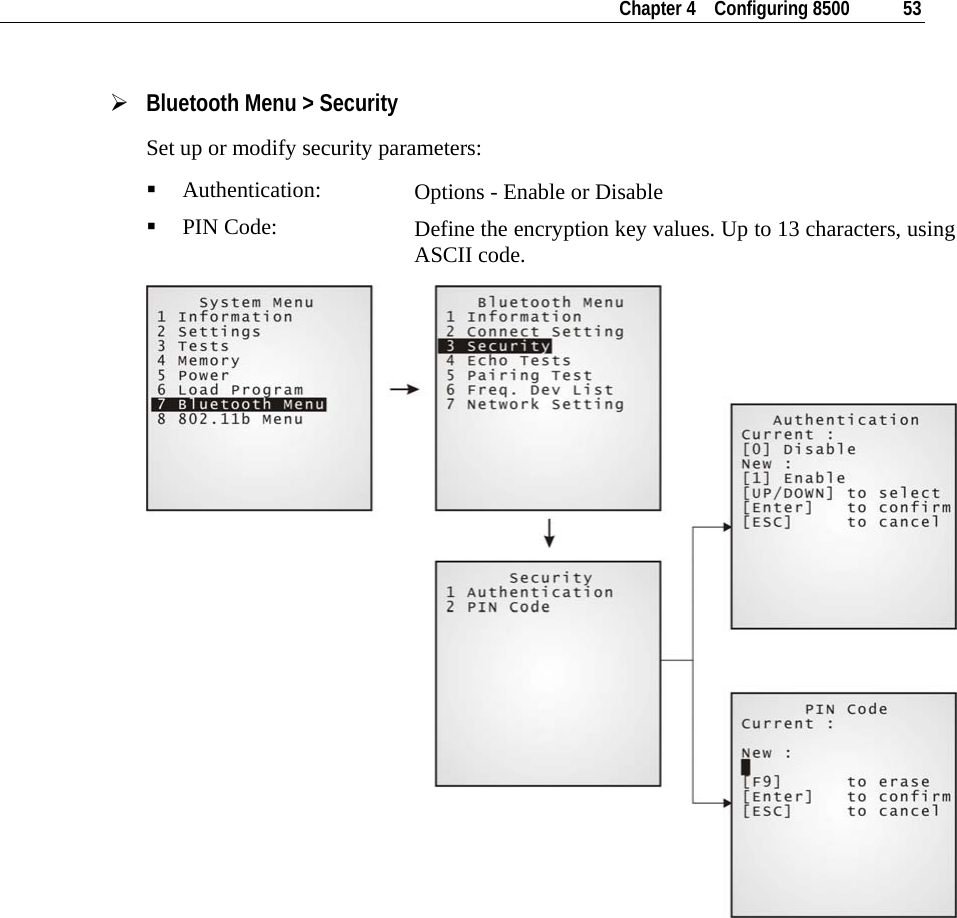
![Chapter 4 Configuring 8500 65 ¾ 802.11b/g Menu > Security Set up or modify security parameters: Authentication [1] Open System: [0] Share Key: Default authentication type This requires implementing WEP key.](https://usermanual.wiki/CipherLab/85002/User-Guide-823769-Page-74.png)
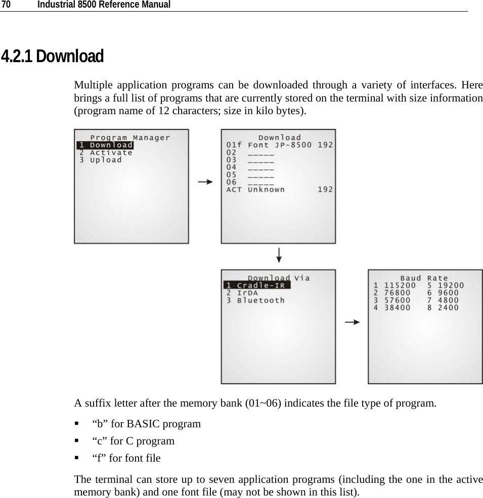
![Chapter 4 Configuring 8500 71 Figure 16: Downloading through Program Manager ¾ Memory Bank 01 ~ 06 Only application program can be downloaded to these banks. Empty bank: Select an empty bank by pressing the corresponding number and then [Enter]. Select baud rate for downloading. Connect cable and wait connecting… To abort the action, press [ESC]. Then press [ESC] again to return to the menu. Occupied bank: If no available banks, you'll have to replace one program with the new one. Select a program that you want to delete by pressing the corresponding number and then [Enter]. The program information is displayed on the screen. Press [Alpha] to enter the capital mode. Then press [C]. Select baud rate for downloading. Connect cable and wait connecting… To abort the action, press [ESC]. Then press [ESC] again to return to the menu. From the menu, you'll find the program is deleted but no new program is present. If you simply want to delete a program, press [D] in step 2. Note: [C], [D] are NOT case sensitive.](https://usermanual.wiki/CipherLab/85002/User-Guide-823769-Page-80.png)
![72 Industrial 8500 Reference Manual ¾ Active Memory Bank Only the application program and font file that need to be activated immediately can be downloaded to the active bank. The new font file may not be shown in the program list if application programs take all banks, but you can view font information in the System Menu. Active bank: Select the active program (may be an empty bank) by pressing the corresponding number (that is 7) and then [Enter]. Connect cable and wait connecting… If the downloaded program is an application, it will replace the active program and come into effect immediately. If it is a font file, then the current active program is still in use. Note: No font file will replace the active application program. 4.2.2 Activate The list shows the entire spare programs stored in the terminal. From the list, you can select from 01 to 06 and activate one of them. ¾ Activate an application program The selected program will be copied to the active memory bank and replace the current one. When <New Program Start> screen prompts “Press [ESC] to clear file”, it means the file system in the SRAM will be cleared out by pressing [ESC]. Then there will be no data (transactions, settings, etc.) stored in the terminal when the new program comes into effect. To keep the data, simply press any other key. ¾ Activate a font file The selected font file will be copied to the active memory bank and replace the current font or system font. However, the active application program will remain intact.](https://usermanual.wiki/CipherLab/85002/User-Guide-823769-Page-81.png)