CipherLab 8600 Mobile Computer User Manual 8600 Reference Manual v1 00 1120
CipherLab Co., Ltd. Mobile Computer 8600 Reference Manual v1 00 1120
UserManual.wiki
>
CipherLab
>
8600 User Manual
Users Manual
Navigation menu
Upload a User Manual
Namespaces
Wiki Guide
HTML
PDF
Info
Views
User Manual
Discussion / Help
Navigation
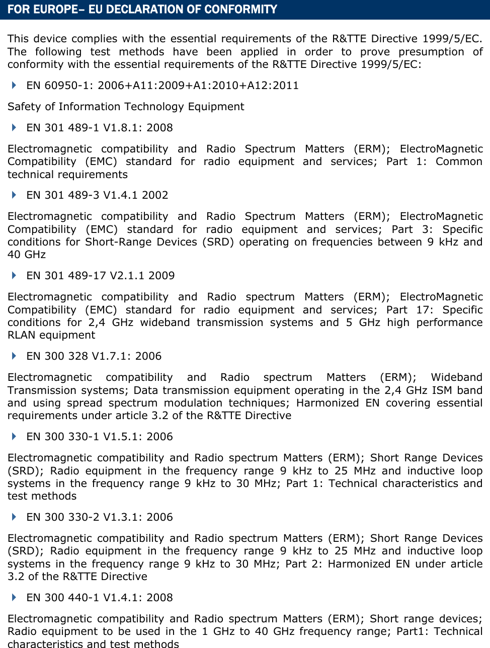

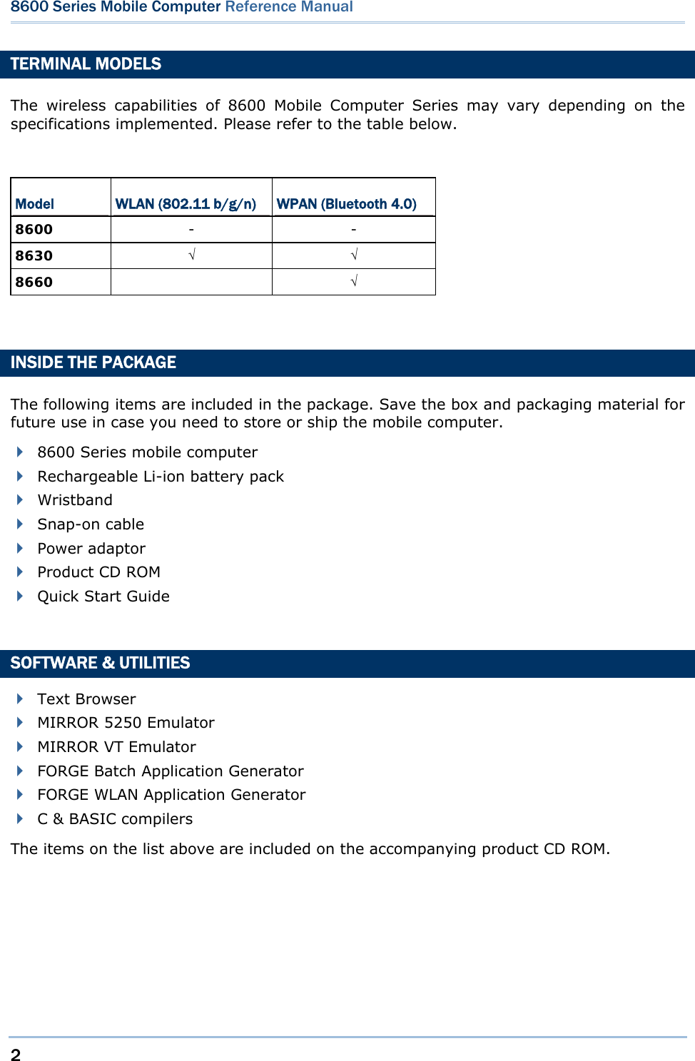
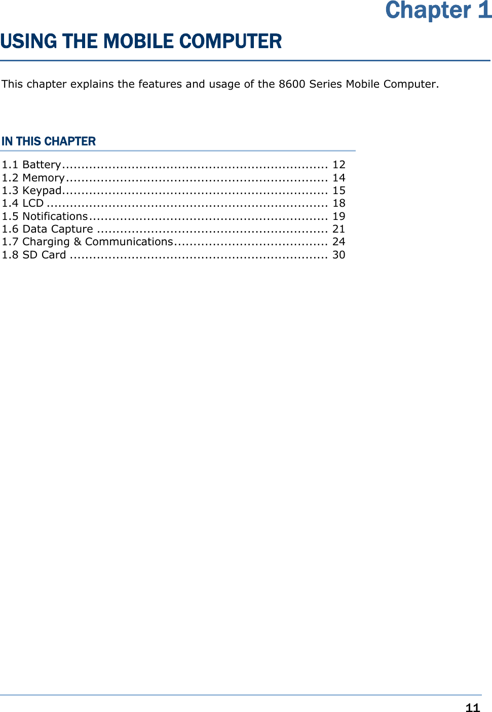
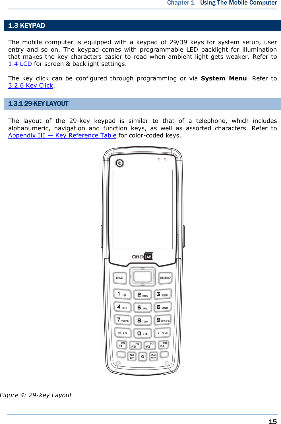
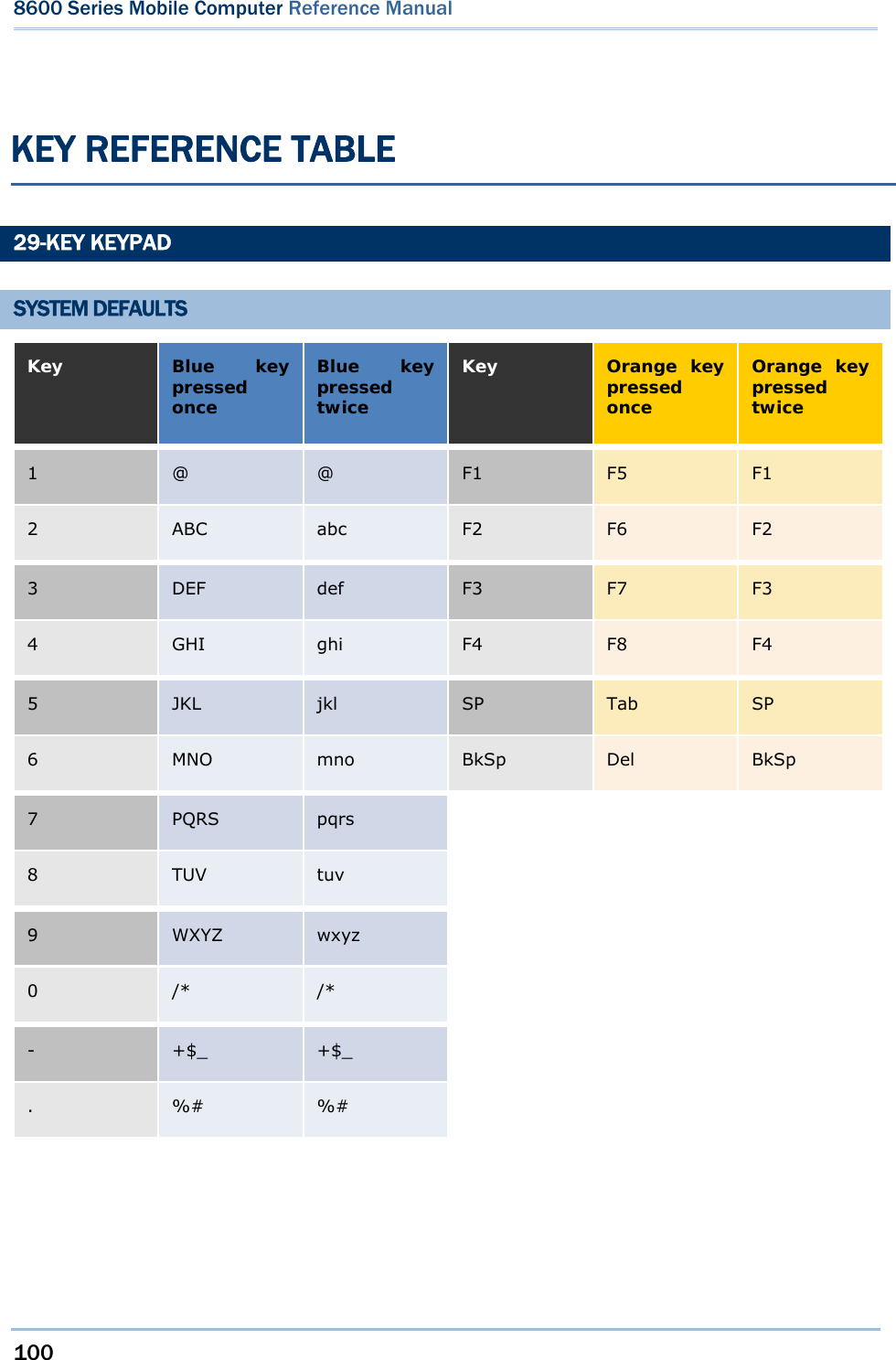
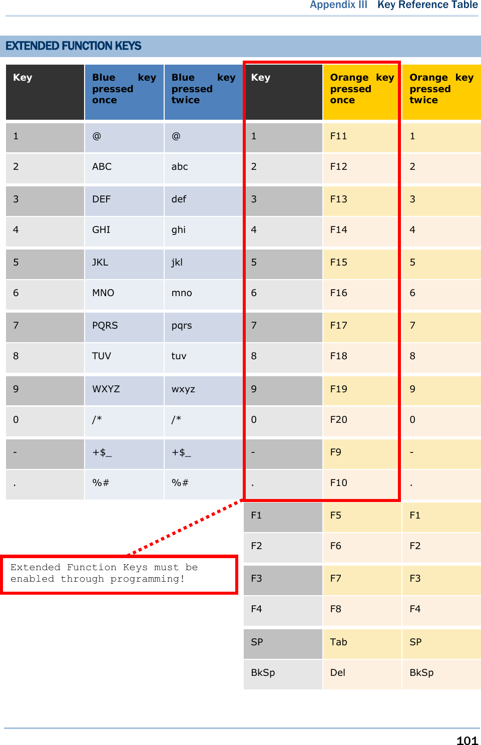
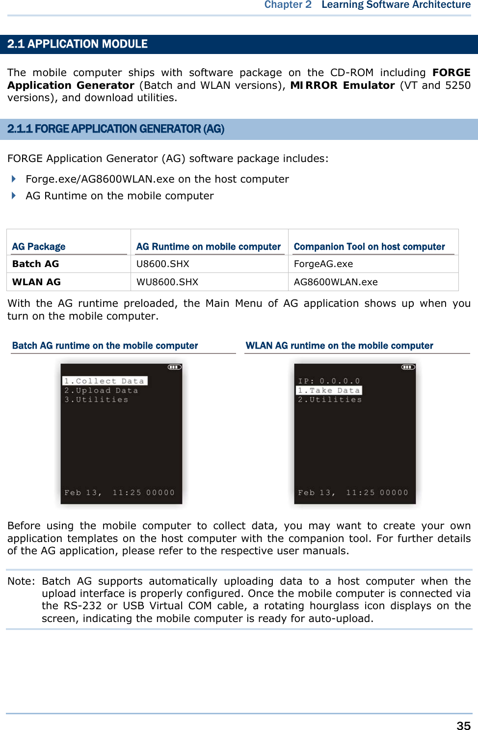
![16 8600 Series Mobile Computer Reference Manual This alphanumeric keypad is set to numeral mode by default. Press the blue key at the bottom-right to toggle between upper-case alphabet, lower-case alphabet, and numeral modes. Press the orange key at the bottom-left to toggle between function and numeral modes. The associated icon will appear on the top-left of the screen in a sequence as shown below. Status Icon Function/Alpha Key Input Mode (none) N/A Numbers A Press the blue key one time Upper-case alphabet a Press the blue key two times Lower-case alphabet F Press the orange key one time Function Mode When in alphabet mode, it takes turns to show upper-case/lower-case alphabets and number when you keep pressing the same key; the lasting time of a press or interval between two presses must not exceed one second or you will always get the first letter. For example, keep pressing the number key [2], it will take turns to show “A”, “B”, “C” or “2” for upper-case, and “a”, “b”, “c” or “2” for lower-case. When you first press the number key [2], it will produce the letter “A” or “a”. When you press the number key [2] twice (the time interval must not exceed one second), it will produce the letter “B” or “b”. When you press the number key [2] three times (the time interval between each press must not exceed one second), it will produce the letter “C” or “c”. When you press the number key [2] four times (the time interval between each press must not exceed one second), it will produce the number “2”. In order to get the desired character, you will need to press the same key, one to four times (the time interval between each press must not exceed one second). Only when you stop pressing the same key for longer than one second or you press another key, will the system send the real key code to the application program. When in function mode, the orange key works with another key. Press the orange key and its associated icon F will be displayed on the top line of the screen. Press the second key, say [Del], to complete the key combination and delete the character where the cursor stays. Press the orange key again and the icon F will go off.](https://usermanual.wiki/CipherLab/8600/User-Guide-2140094-Page-28.png)
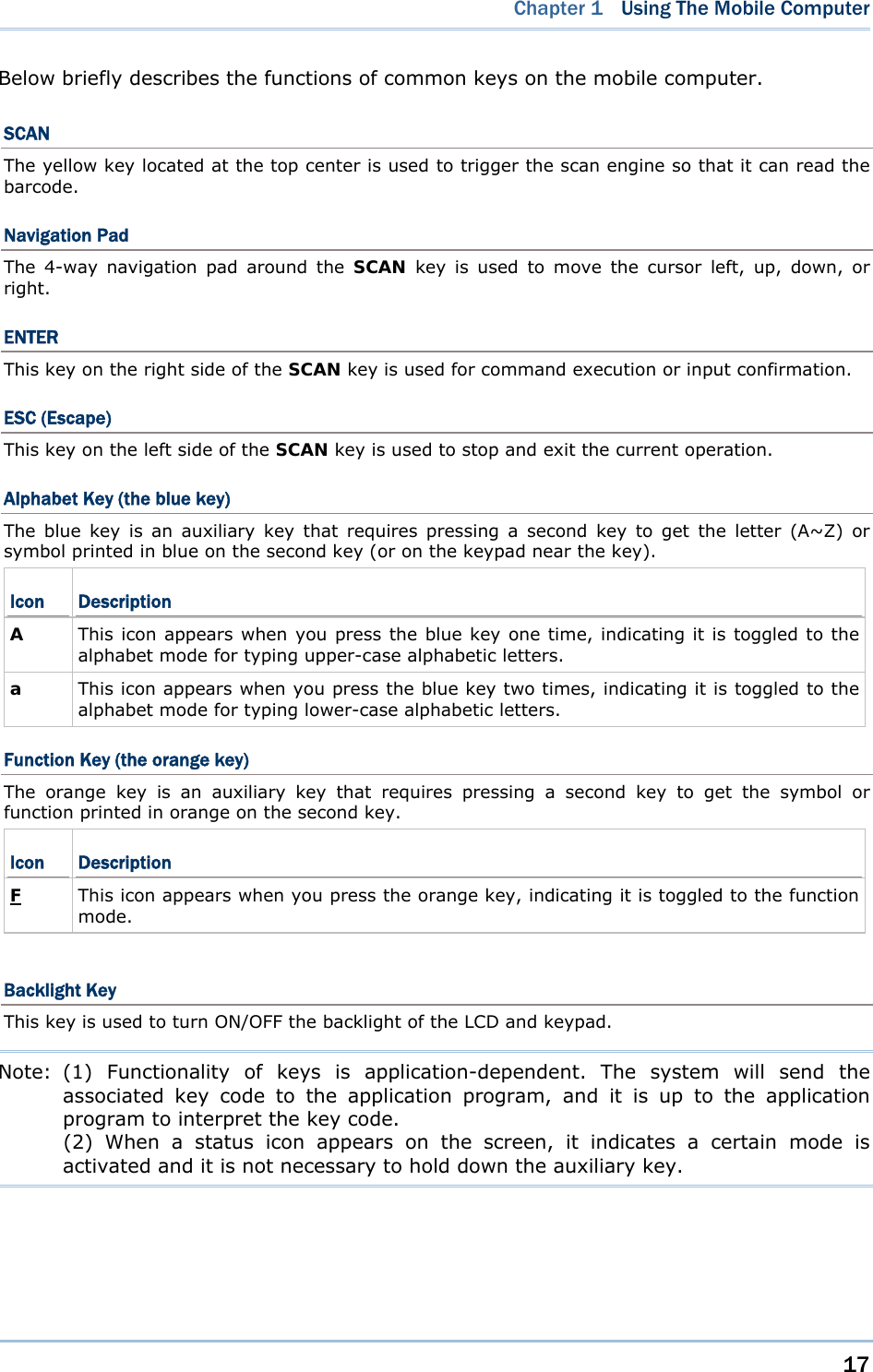
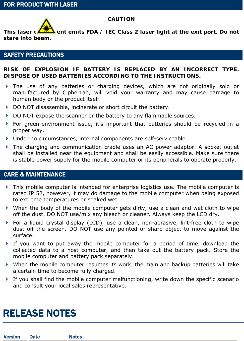
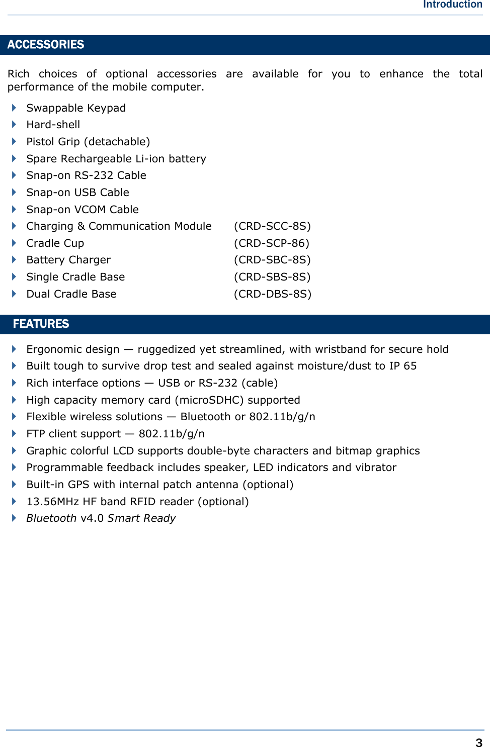
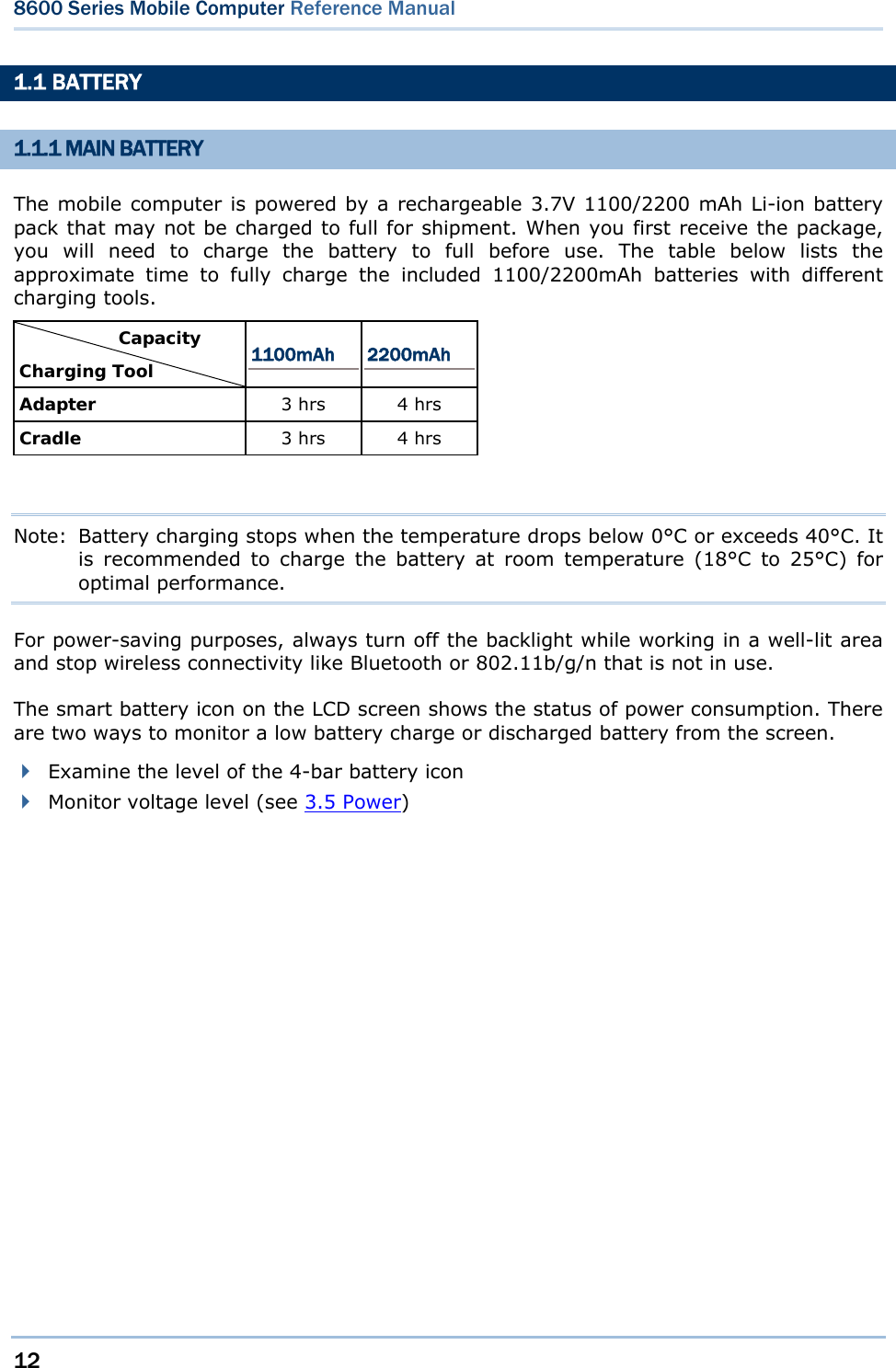
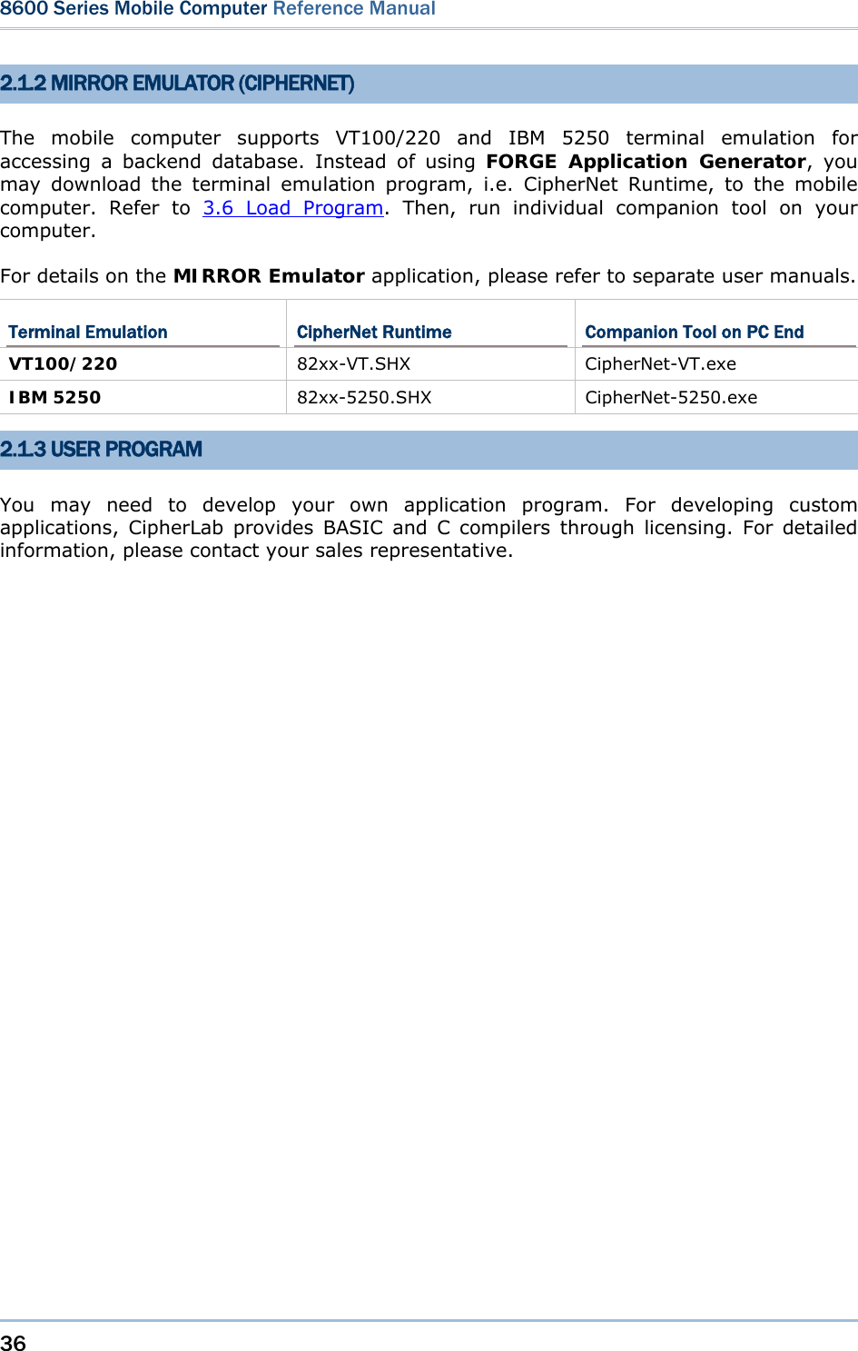
![18 8600 Series Mobile Computer Reference Manual 1.4 LCD The mobile computer comes with a TFT graphic LCD, 240 by 320 pixels resolution, which can be programmed to display text or graphics, such as specific font and company logo, to meet varying application needs. Options Font Size (pixels) Characters by lines English font Font size 10×20 (pixels) Font size 12×24 (pixels) 24 characters by 16 lines 20 characters by 13 lines Chinese font Font size 20×20 (pixels) Font size 24×24 (pixels) 12 characters by 16 lines 10 characters by 13 lines Other language fonts, company logo… Programmable Note: The top line (icon zone) is reserved to display status icons, such as icons indicating battery status, alphabet upper/lower case, SD card installed. Therefore, the actual amount of lines will be less than the total count by 1. 1.4.1 ADJUSTING THE LCD BACKLIGHT The backlight of screen helps ease reading in dim environments. It can be turned on/off by pressing the [ ] key located at the bottom center of the keypad. Also backlight level can be adjusted through programming or via System Menu. Refer to 3.2.2 Backlight and 3.2.3 Contrast. Using backlight while on battery power will substantially reduce battery power. We suggest that you switch off the backlight while there’s no need to read the screen or have it set to be automatically turned off when it has been idle for a certain period of time.](https://usermanual.wiki/CipherLab/8600/User-Guide-2140094-Page-30.png)
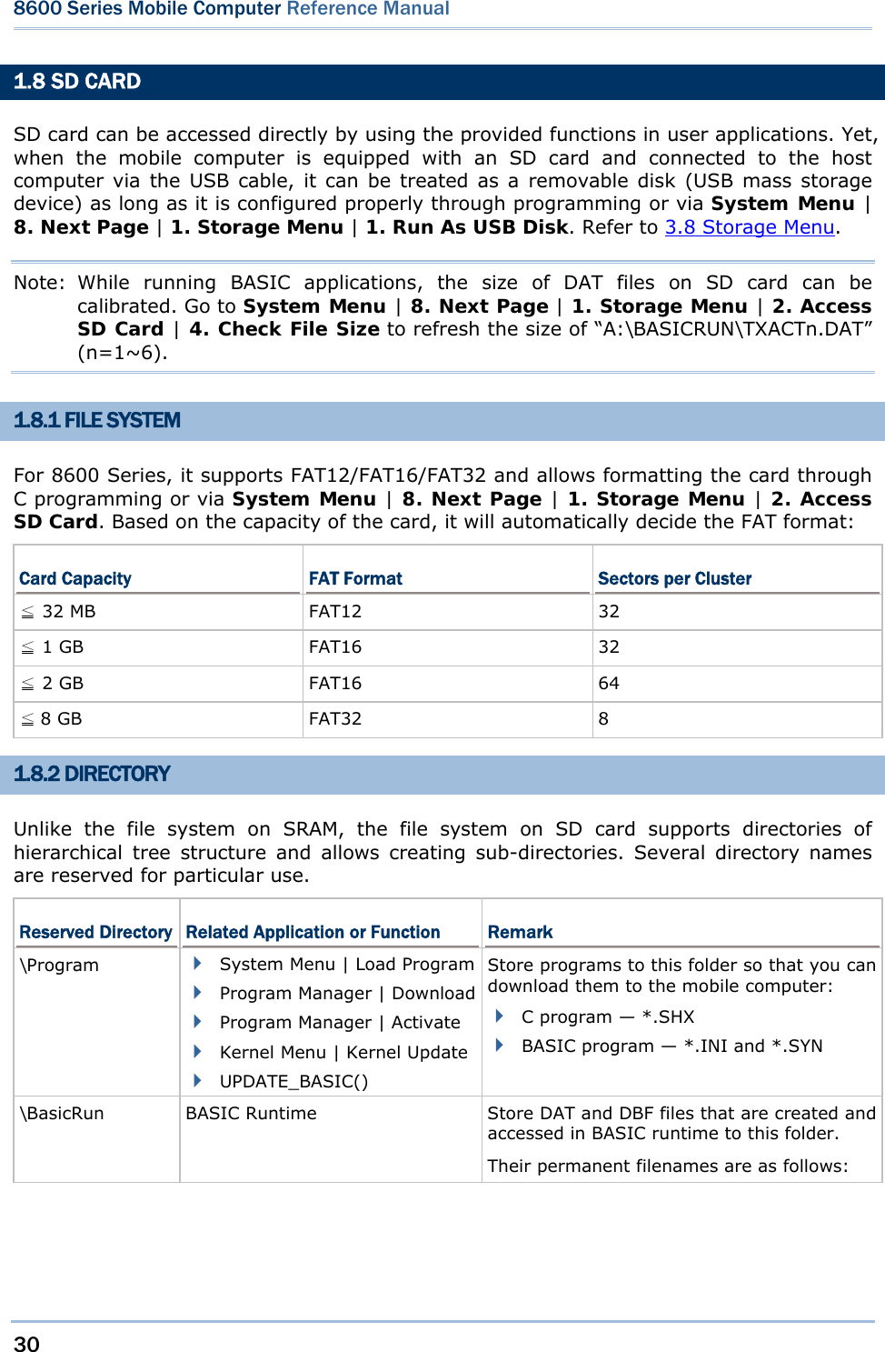
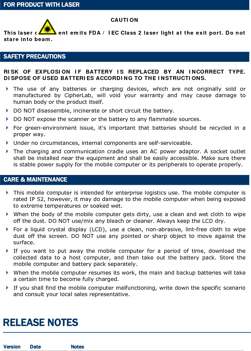
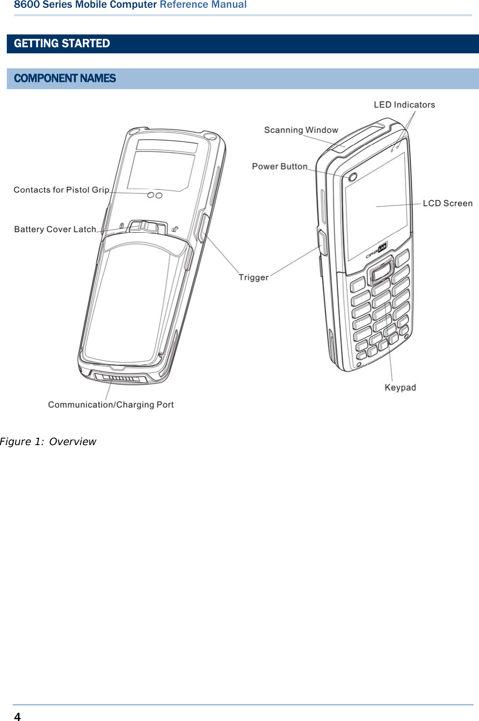
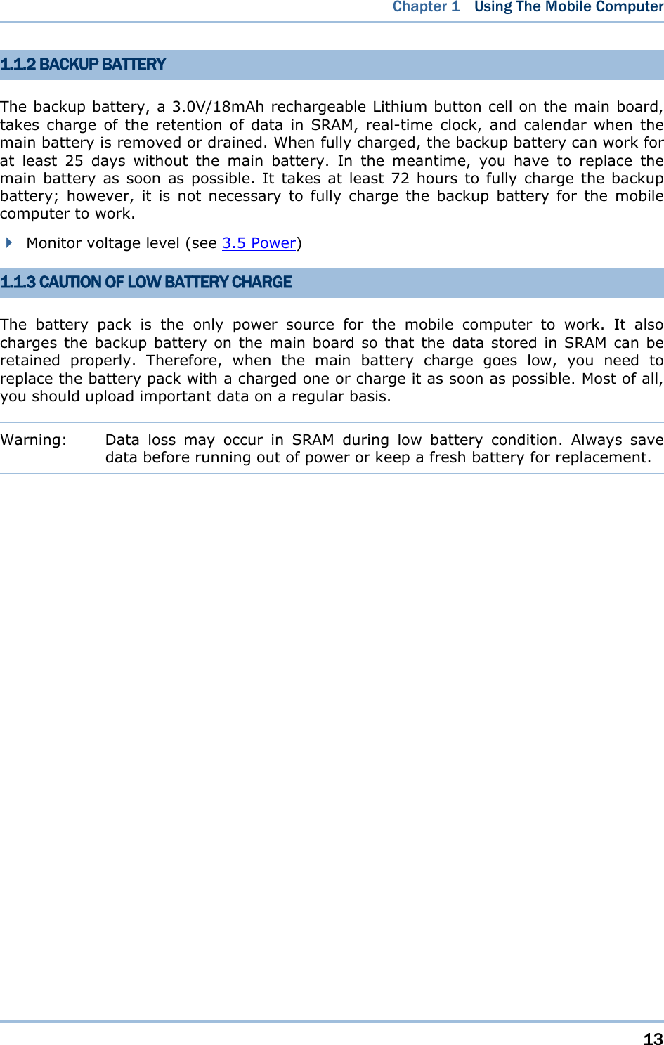
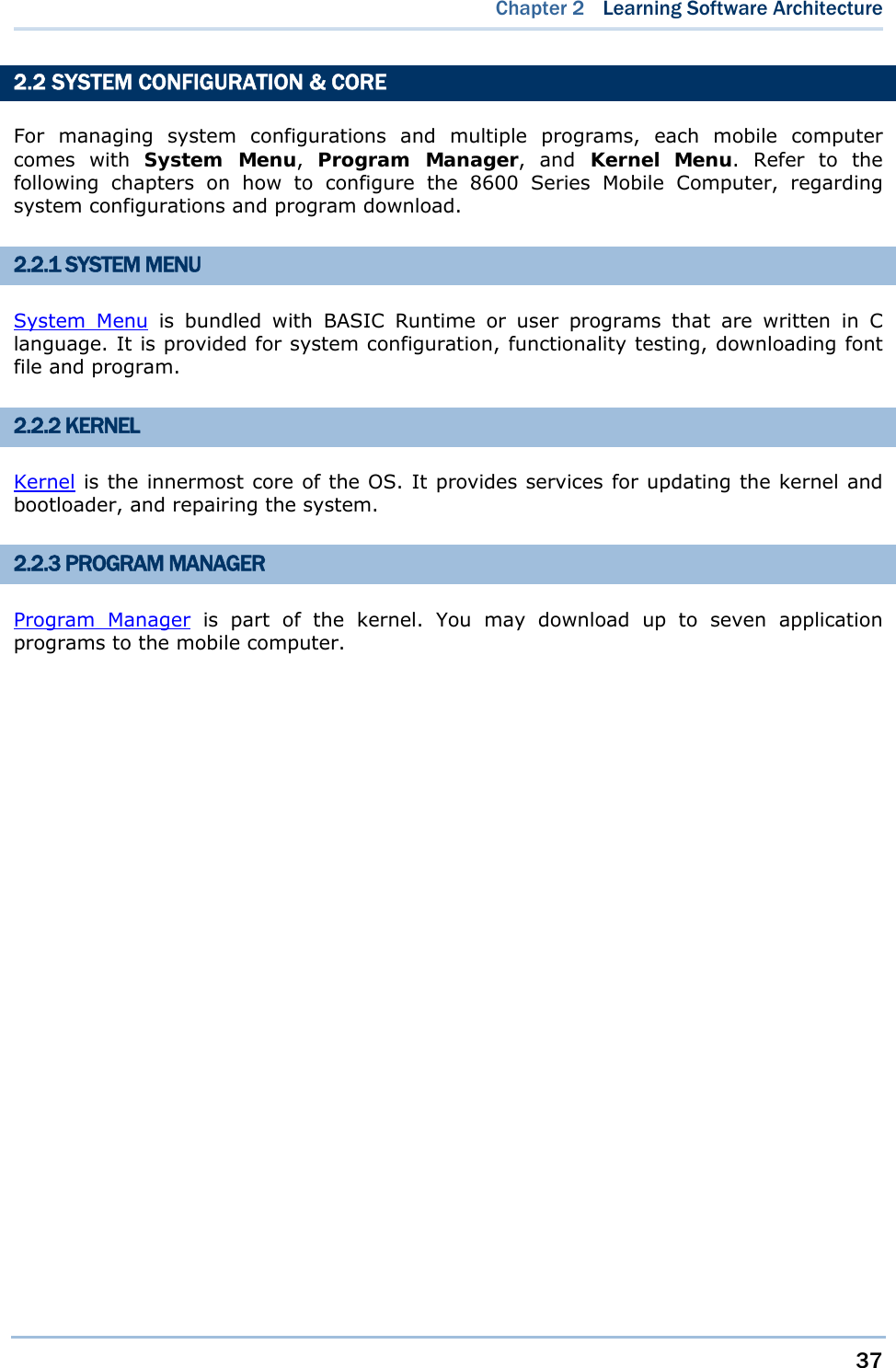
![32 8600 Series Mobile Computer Reference Manual \AG\DBF \AG\DAT \AG\EXPORT \AG\IMPORT Application Generator (a.k.a. AG) Store DAT, DBF, and Lookup files that are created and/or accessed in Application Generator to this folder. 1.8.3 FILE NAME A file name must follow 8.3 format (= short filenames) — at most 8 characters for filename, and at most three characters for filename extension. The following characters are unacceptable: “ * + , : ; < = > ? | [ ] The mobile computer can display a filename of 1 ~ 8 characters (the null character not included), and filename extension will be displayed if provided. If a file name specified is longer than eight characters, it will be truncated to eight characters. Long filenames, at most 255 characters, are allowed when using the mobile computer equipped with SD card as a mass storage device. For example, you may have a filename “123456789.txt” created from your computer. However, when the same file is directly accessed on the mobile computer, the filename will be truncated to “123456~1.txt”. If a file name is not specified in ASCII characters, in order for the mobile computer to display it correctly, you may need to download a matching font file to the mobile computer first. The file name is not case-sensitive.](https://usermanual.wiki/CipherLab/8600/User-Guide-2140094-Page-44.png)
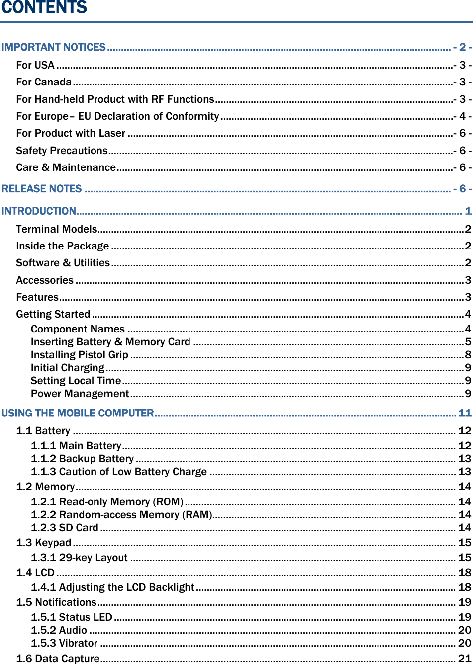
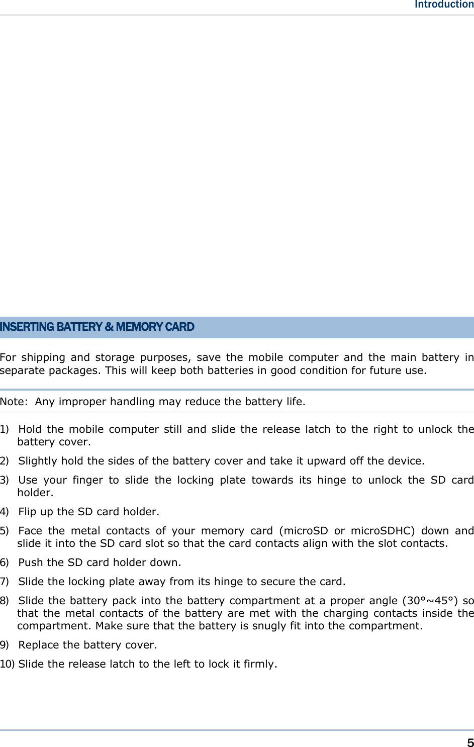
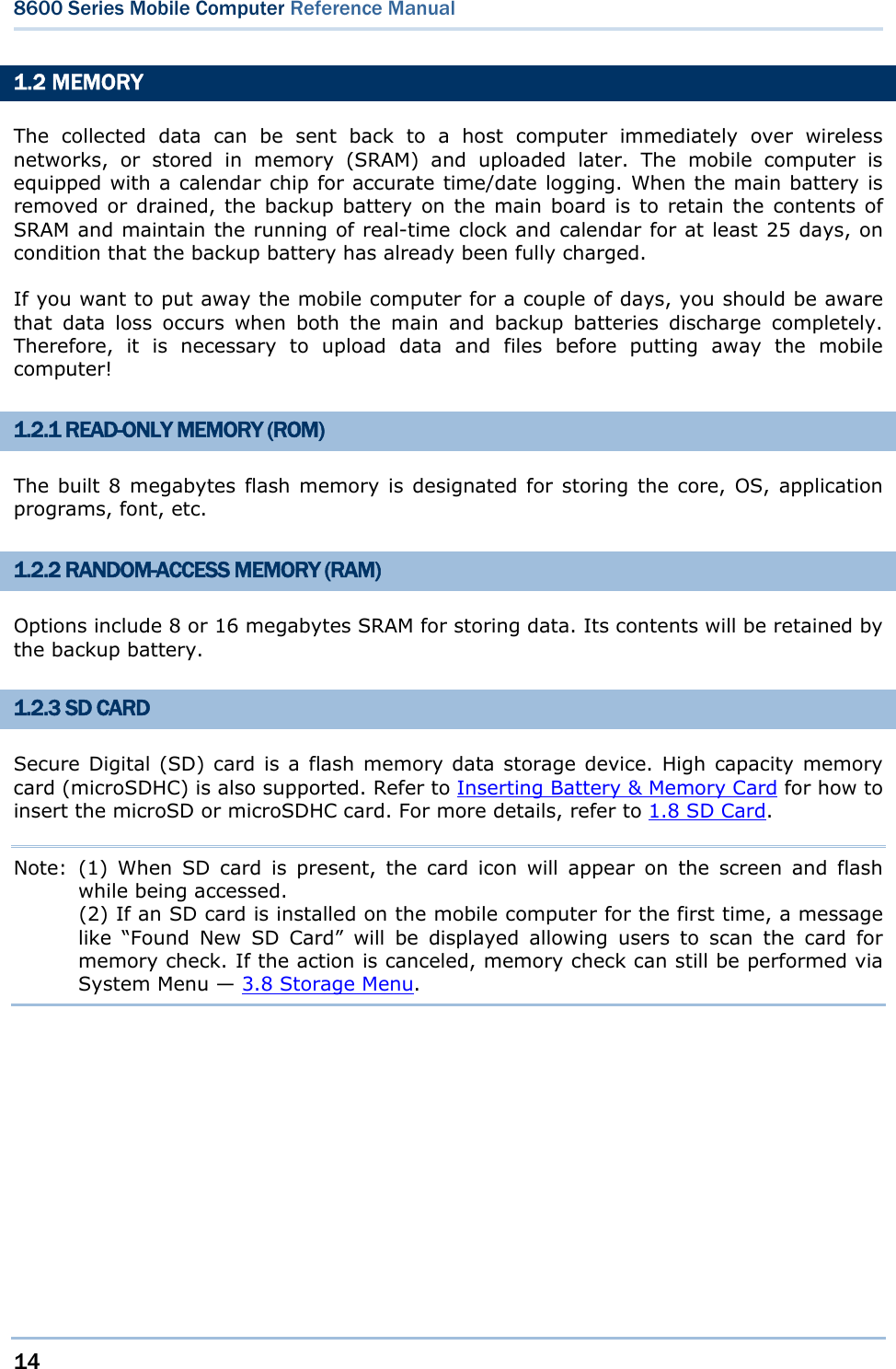
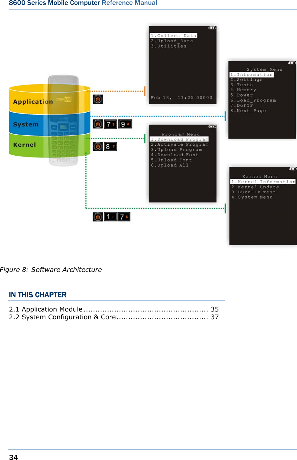
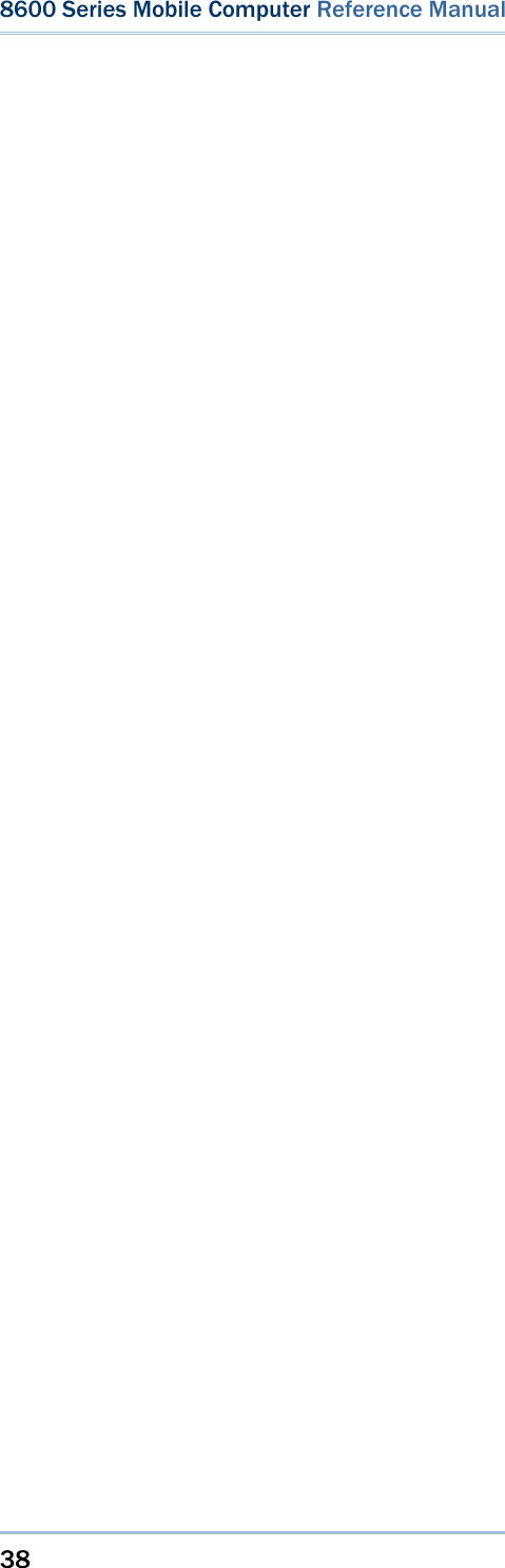
![33 This chapter mainly describes the software inside the mobile computer. It consists of three modules — Kernel, System, and Application; each has a function menu. When a menu is displayed, you may select an item by either of the following ways: Press the arrow keys [Up] and [Down] to move the highlight bar. Press the number key that corresponds to the item number. Follow the on-screen instructions to change a specific setting, or press [ESC] to return to a previous page or menu. On each screen, the top line displays status icons, such as: The 4-bar battery icon indicates the current power status. The status icon of input mode or function mode is controlled by the blue/orange key. Chapter 2 LEARNING SOFTWARE ARCHITECTURE](https://usermanual.wiki/CipherLab/8600/User-Guide-2140094-Page-45.png)
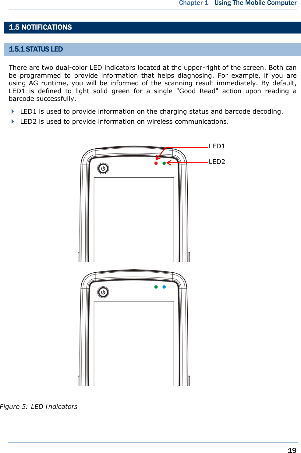
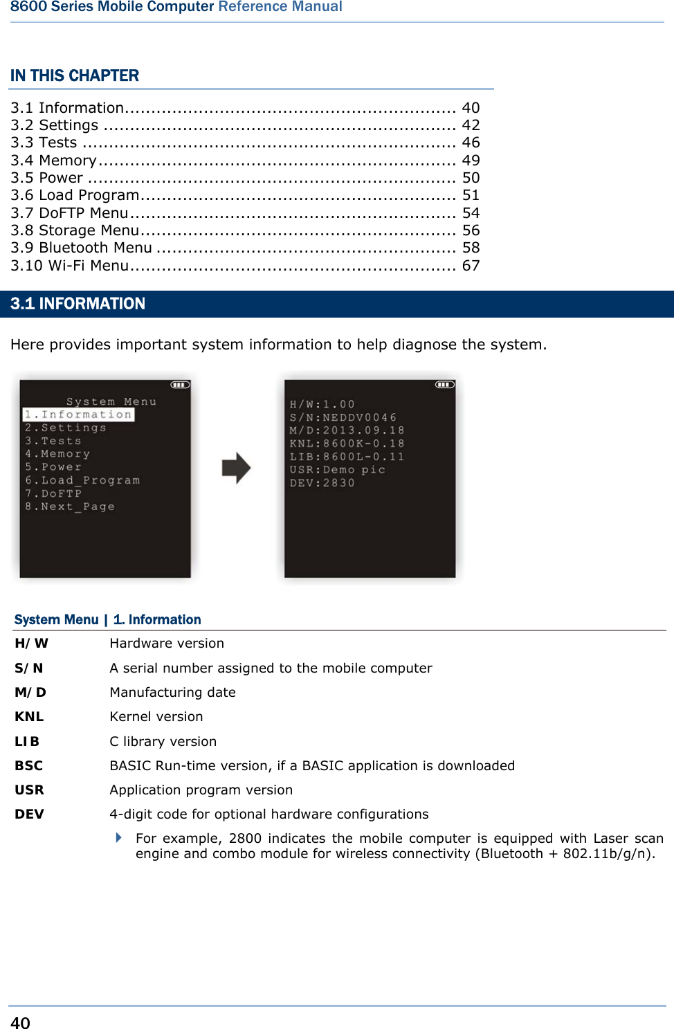
![39 System Menu offers an interface for engineers (programmers or system integrator) to view system information, change the configuration parameters, download programs and run diagnostics. This menu is designed for engineering tests and maintenance ONLY. For this reason, it provides password protection to prevent unauthorized users from accidentally changing system settings. Warning! System Menu is NOT for the use of any end users. The system password helps ensure system safety and integrity. How to access System Menu? 1) Turn off the mobile computer. 2) Press [7] + [9] + [Power]. Chapter 3 SYSTEM MENU](https://usermanual.wiki/CipherLab/8600/User-Guide-2140094-Page-51.png)

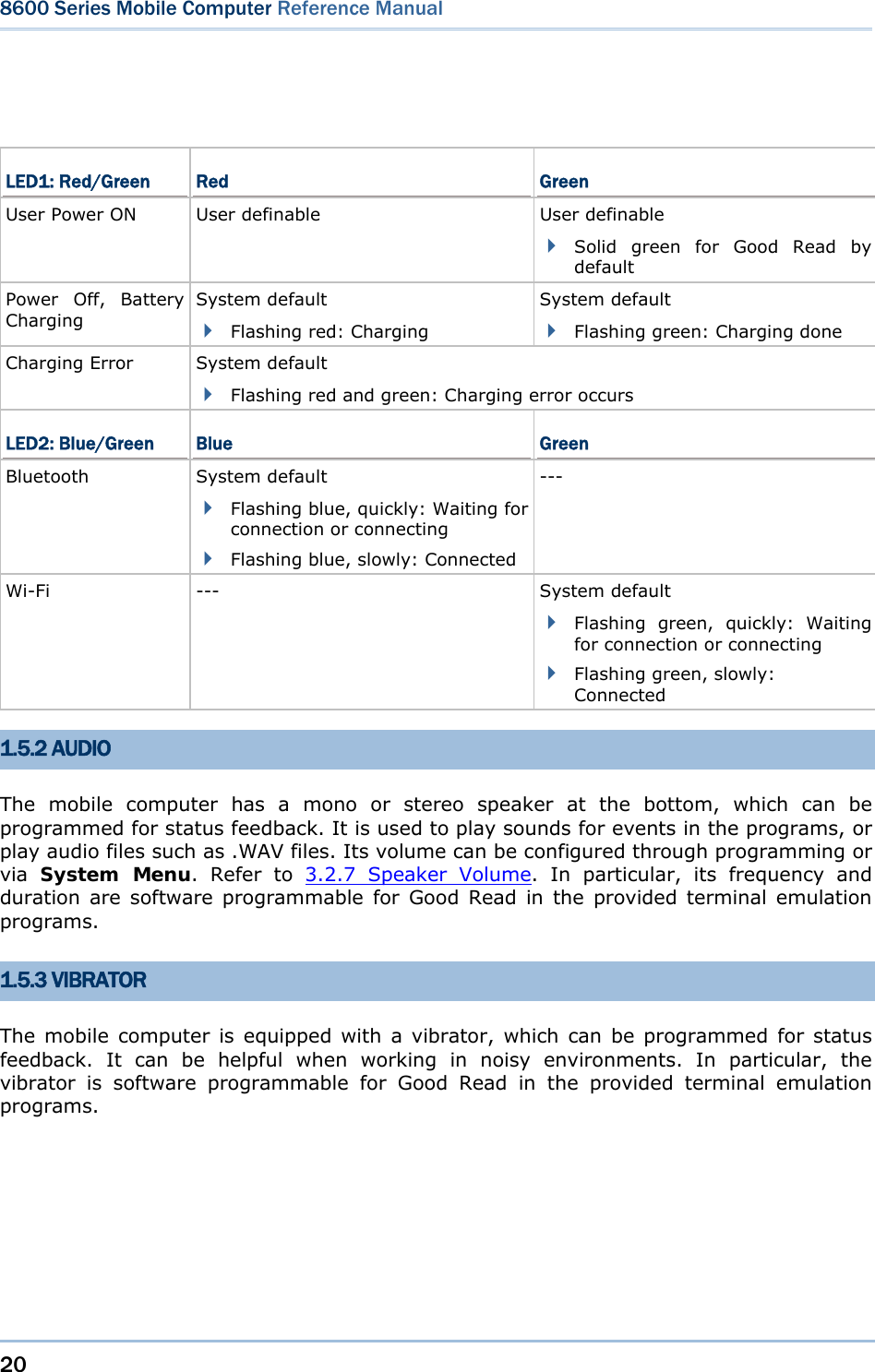
![42 8600 Series Mobile Computer Reference Manual 3.2 SETTINGS You can change the default settings here. System Settings Default Values Clock Current time Backlight 20 seconds at level 2, backlight shade enabled Contrast Level 4 Auto Off 10 minutes Power On Options Program Resume Key Click Tone 2 Speaker Volume High volume level USB VCOM No. Fixed USB Charge Current 500 mA System Password Open access Font System font Default Set (=Reset to Default) Load factory settings Reset Reader Restore default reader settings 3.2.1 CLOCK Set date and time for Real Time Clock. Enter two digits for the year, e.g. 04 for 2004. 3.2.2 BACKLIGHT Set the backlight duration for the keypad and LCD. Enter a value between 0 and 9999 (second). Press the arrow keys [Up] and [Down] to adjust the backlight level (4 levels). Press the [Left] key to adjust the shade effect.](https://usermanual.wiki/CipherLab/8600/User-Guide-2140094-Page-54.png)
![43 Chapter 3 System Menu 3.2.3 CONTRAST Set the contrast level for the LCD. Press the arrow keys [Up] and [Down] to adjust the contrast level. 3.2.4 AUTO OFF The mobile computer will be turned off automatically when no operation is taking place during a specified period of time. Enter a value between 0 and 999 (minute). Note: To disable this function, enter 0. 3.2.5 POWER ON (& WAKEUP EVENT) OPTIONS Set the startup screen once the mobile computer is turned on, and specify which events will wake up the mobile computer: Power On Options Press the arrow keys [Up] and [Down] to select “Program Resume” or “Program Restart”, and then press [ENTER]. Program Resume: When selected, the mobile computer will start from the last session of program before it is turned off. Program Restart: When selected, the mobile computer will start from the first session of the program. WakeUp Events The specified events can wake up the mobile computer when the conditions are met. Press the arrow keys [Up] and [Down] to select a specific event, and press [ENTER] to determine when it is treated as a wake-up event or not. PwrKey: If yes, it will wake up the mobile computer upon pressing the Power key. RS-232: If yes, it will wake up the mobile computer upon connecting the RS-232 cable. USB: If yes, it will wake up the mobile computer upon connecting the USB cable. Charging: If yes, it will wake up the mobile computer upon getting charged via the cradle or direct charging. Charged: If yes, it will wake up the mobile computer upon completion of charging. Alarm: If yes, it will wake up the mobile computer upon the alarm time is up. Alarm can be set up through programming only.](https://usermanual.wiki/CipherLab/8600/User-Guide-2140094-Page-55.png)
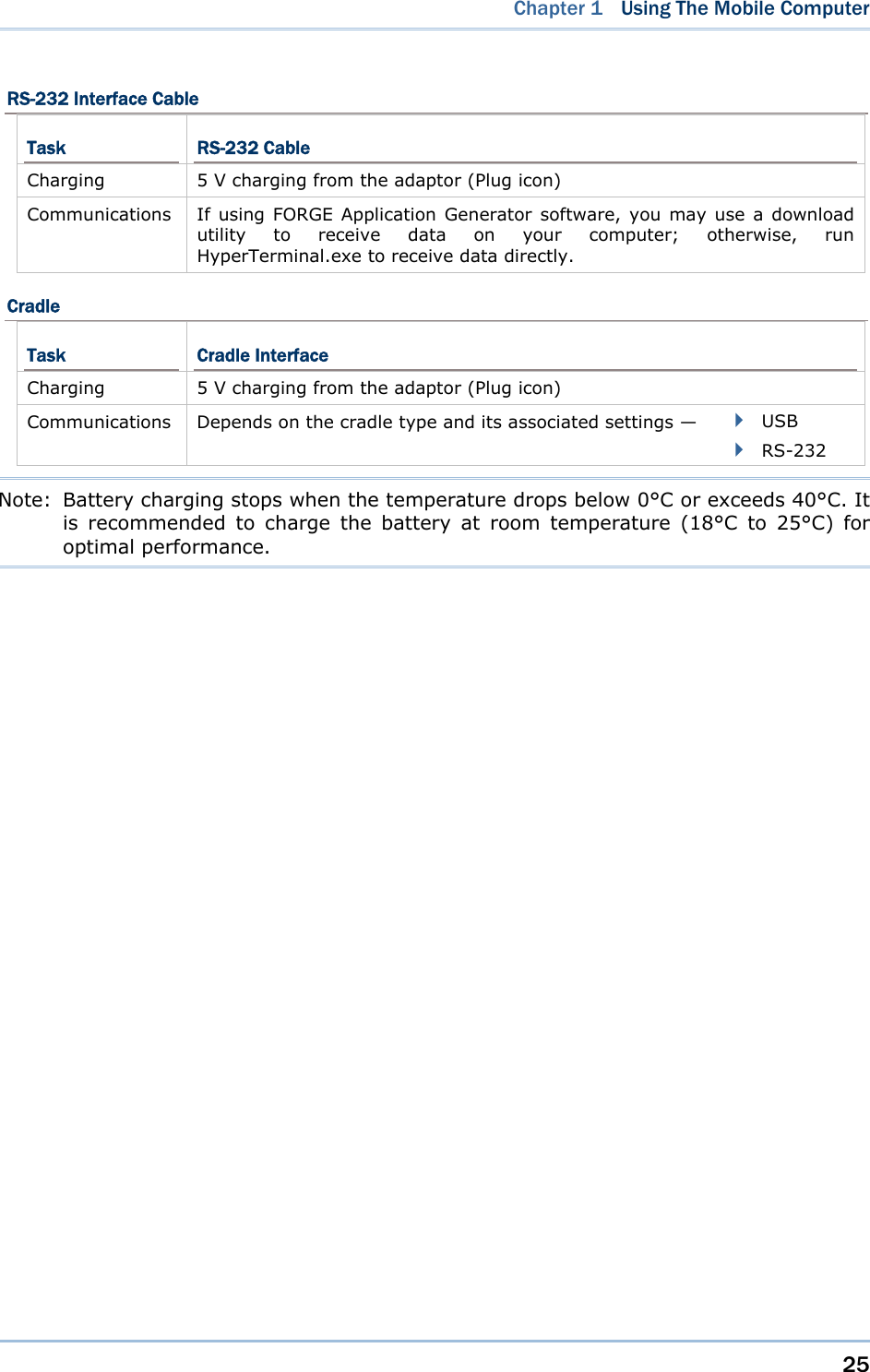
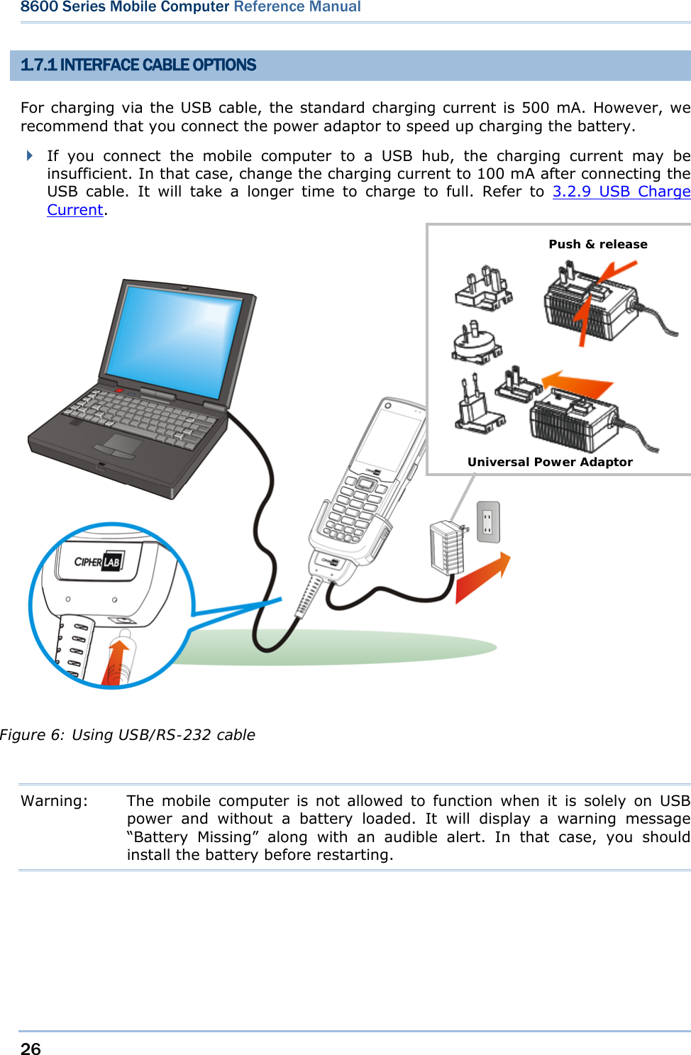
![44 8600 Series Mobile Computer Reference Manual 3.2.6 KEY CLICK The system will produce an audible signal when any key on the keypad is pressed. The current value is highlighted. Select a desired tone for the speaker or mute it. 3.2.7 SPEAKER VOLUME Set the speaker volume. Press the arrow keys [Up] and [Down] to adjust the volume level (3 levels) or mute it. 3.2.8 USB VCOM NO By default, it is set to use one virtual COM port for all (=FIXED), regardless of how many 8600 mobile computers are connected to PC when USB Virtual COM is in use. This setting requires you to connect one 8600 at a time, and will facilitate configuring a great amount of 8600 mobile computers via the same virtual COM port (for administrators’ or factory use). If necessary, you can have it set to use variable virtual COM port (=Change by Serial Number), which will vary by the serial number of each different 8600. Press the arrow keys [Up] and [Down] to select between “Fixed” and “Change by Serial Number”. 3.2.9 USB CHARGE CURRENT By default, the USB charging current is set to 500 mA. For direct charging via the USB cable without supplying a power adaptor, the standard charging current is 500 mA. If you connect the mobile computer to a USB hub, the charging current may be insufficient. In that case, change the charging current to 100 mA after connecting the USB cable. It will take a longer time to charge to full. Press the arrow keys [Up] and [Down] to select between “500 mA” and “100 mA”. To disable charging for 8600, select “0 mA”. Note: (1) USB direct charging, 500 mA: USB icon (2) USB direct charging, 100 mA: Highlighted USB icon (3) 5V charging from the adaptor: Plug icon 3.2.10 FONT Font version information can be viewed here. It displays System Font if there is no custom font file. If a multi-language font file is downloaded, you will be able to select a font from the list.](https://usermanual.wiki/CipherLab/8600/User-Guide-2140094-Page-56.png)
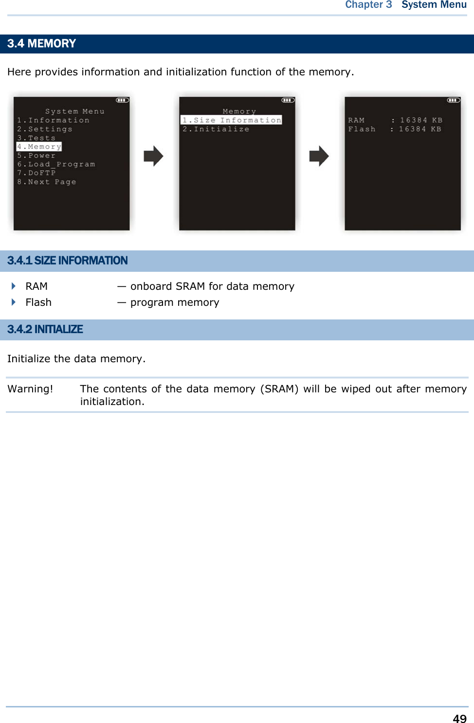
![46 8600 Series Mobile Computer Reference Manual 3.3 TESTS Here provides functional tests for key parts. 3.3.1 READER Test the reading performance of the scanner. The supported symbologies depend on the scan engine you use. Refer to 1.6 Data Capture for symbologies that are enabled by default. For symbologies that are disabled by default, they must be enabled through programming. Press [SCAN] to start. To stop and exit the test, press any key. 3.3.2 SPEAKER Test the speaker with different volume levels. To stop and exit the test, press any key. 3.3.3 LCD & LED Test the LCD display and LED indicators. To stop and exit the test, press any key. 3.3.4 KEYBOARD Test the rubber keys. Press any key and its corresponding character will be shown on the screen. To stop and exit the test, press [ESC]. 3.3.5 MEMORY Test the data memory (SRAM), and the results will be shown on the screen. To stop and exit the test, press [ESC].](https://usermanual.wiki/CipherLab/8600/User-Guide-2140094-Page-58.png)
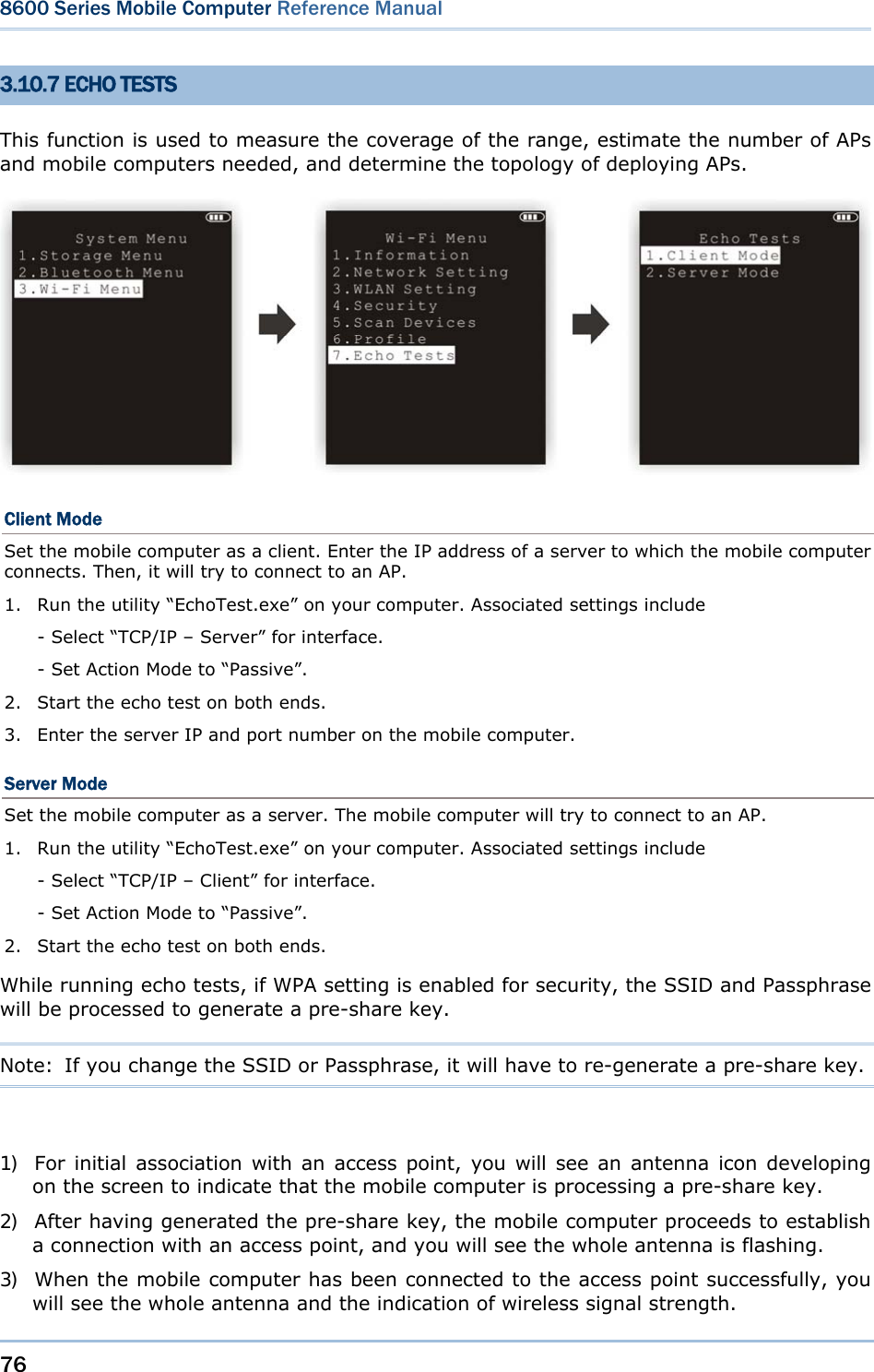
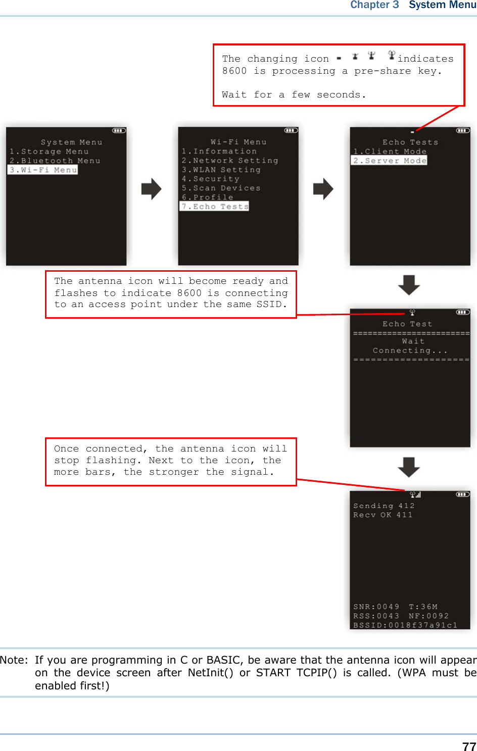
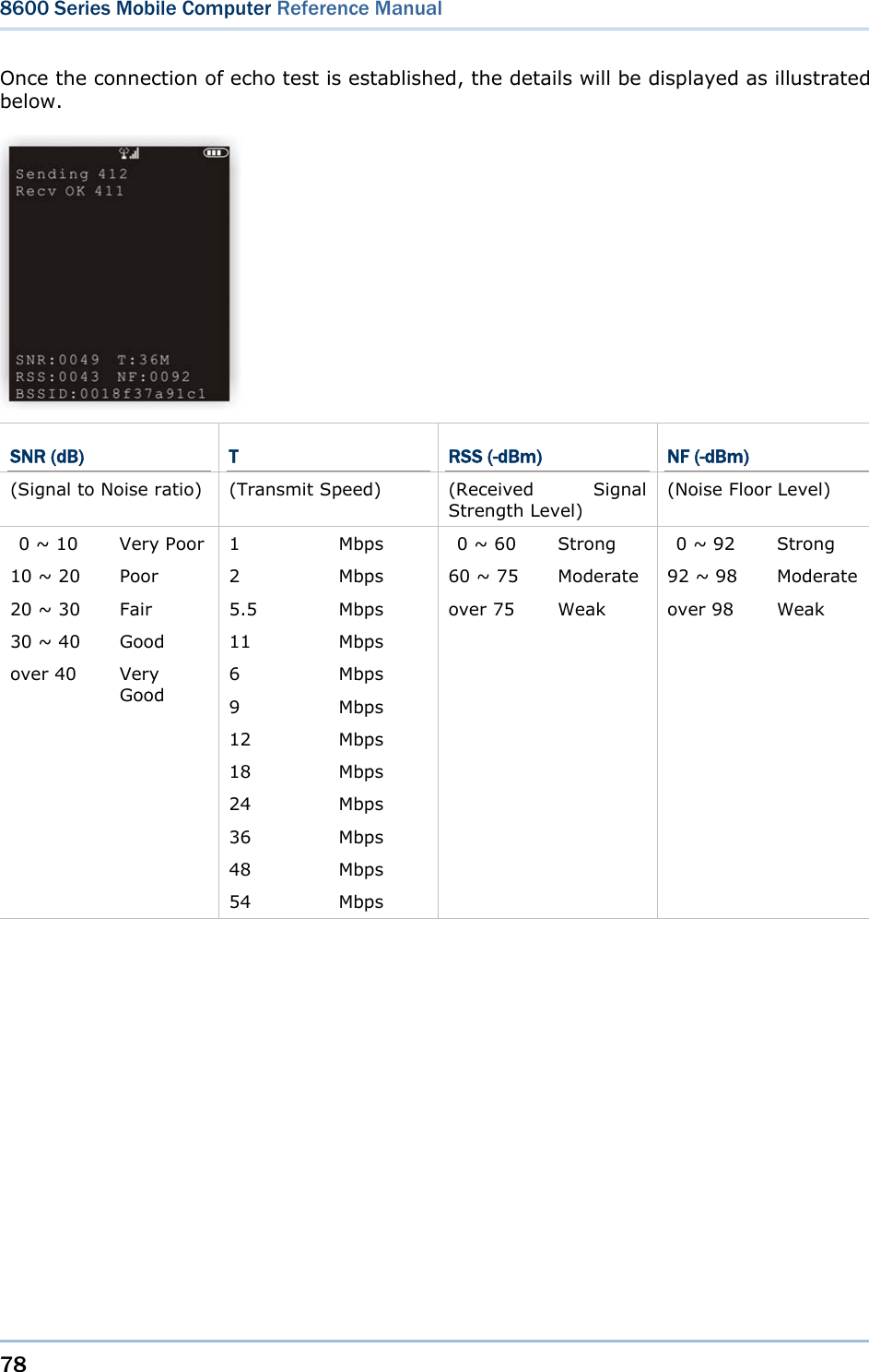
![47 Chapter 3 System Menu Warning! The contents of the data memory (SRAM) will be wiped out after test. 3.3.6 ECHO TEST After a physical connection is established properly, run a test utility on your computer and start the test on your mobile computer. Select a desired baud rate if necessary. To stop and exit the test, press [ESC]. Interface Description Test Utility RS-232 This echo test is to verify connectivity via the RS-232 cable between the mobile computer and a host computer. EchoTest.exe 308 USB This echo test is to verify the connectivity via the 308 USB cable between the mobile computer and a host computer. EchoTest.exe USB This echo test is to verify connectivity via the USB cable between the mobile computer and a host computer. USB VCOM Echo — The mobile computer works as a generic USB device. EchoTest.exe for Virtual COM USB HID — The mobile computer works as an input device; select keyboard type and Caps Lock status for running a test. Any text editor for HID USB VCOM_CDC Echo — The mobile computer works as a generic USB device. EchoTest.exe for Virtual COM 3.3.7 VIBRATOR Select this item to test the vibrator. To stop and exit the test, press [ESC]. 3.3.8 RFID Select this item to test the RFID Reader. Press [ESC] to exit. 3.3.9 GPS Select this item to test the GPS receiver of the device. Interface Description Latitude Displays the latitude where the device is located. Longit. Displays the longitude where the device is located. Speed Displays the moving speed in kilometers per hour. Altitude Displays the altitude in meters.](https://usermanual.wiki/CipherLab/8600/User-Guide-2140094-Page-59.png)
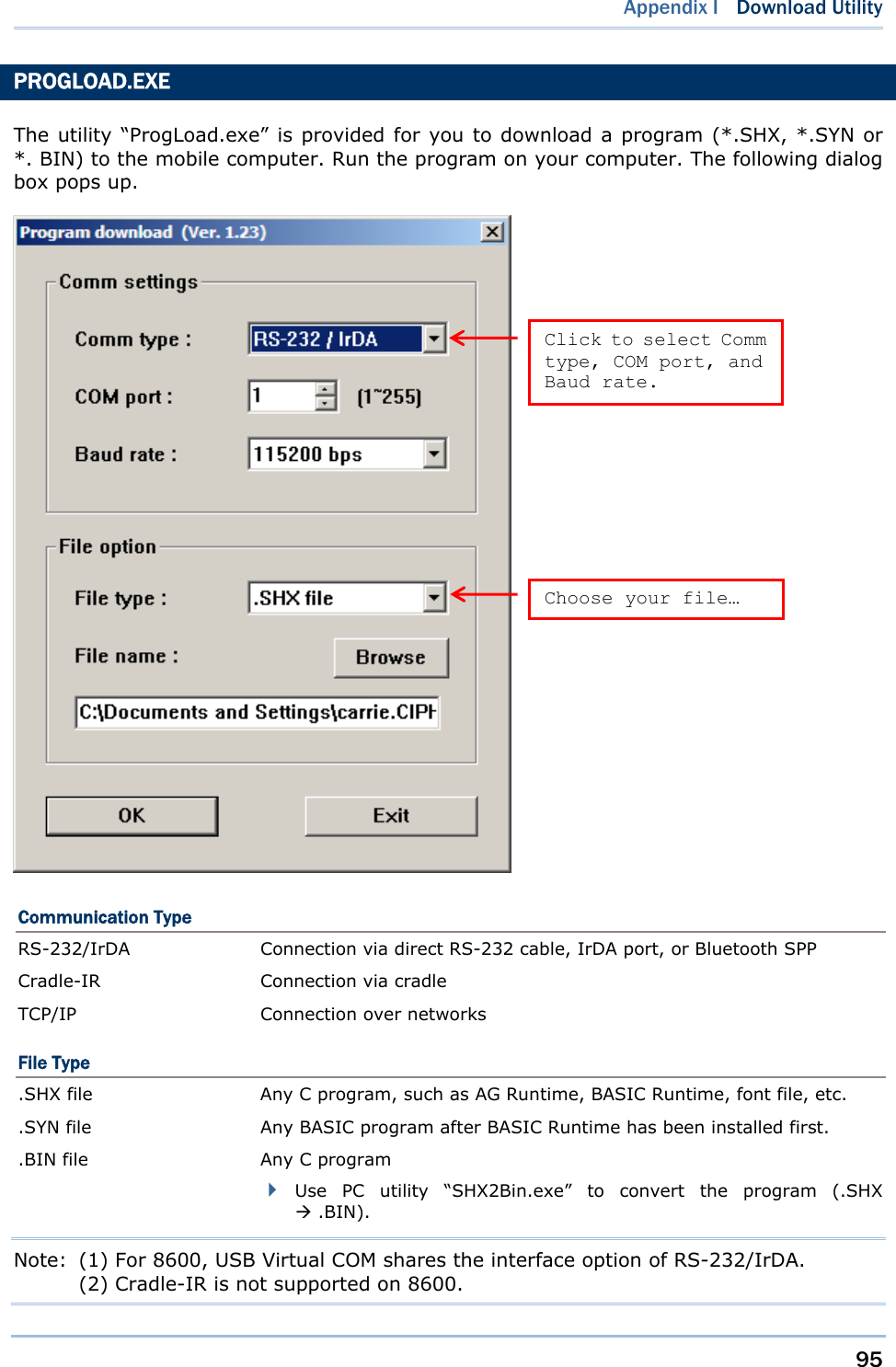
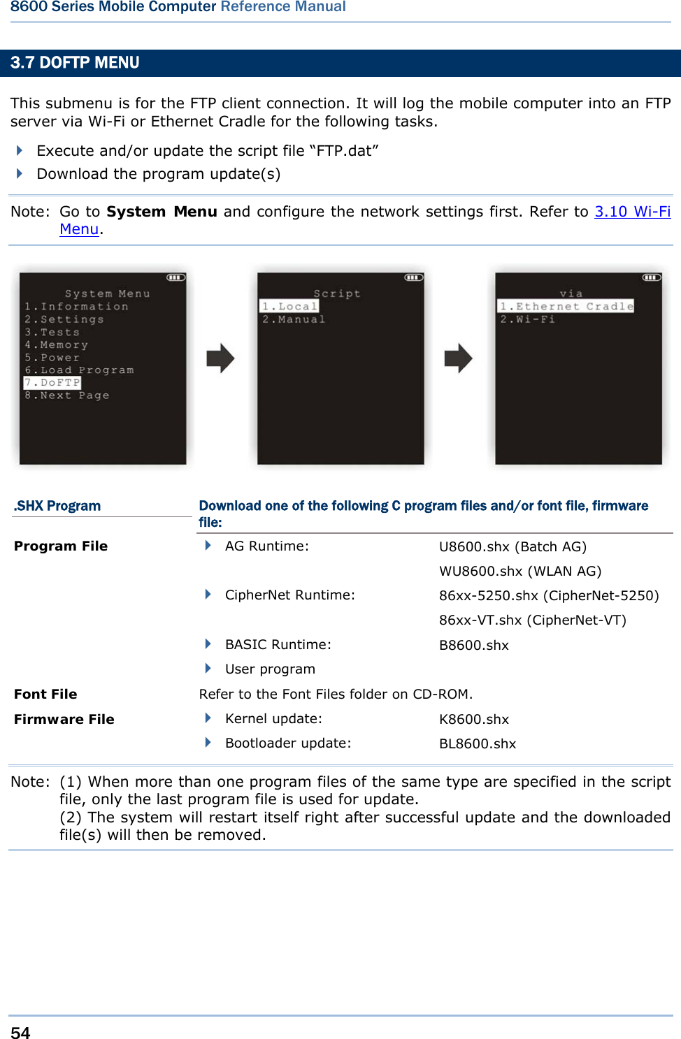
![51 Chapter 3 System Menu 3.6 LOAD PROGRAM Here you can access the Load Program service provided by the kernel. Because the kernel will take over the job, you will not be able to return to System Menu by pressing [ESC]. After downloading, restart the mobile computer to activate the new program. Refer to Appendix I Download Utility. Note: The mobile computer will stay in download mode for approximately 30 seconds. .SHX Program Download one of the following C program files and/or font file: Program File AG Runtime: U8600.shx (Batch AG) WU8600.shx (WLAN AG) CipherNet Runtime: 86xx-5250.shx (CipherNet-5250) 86xx-VT.shx (CipherNet-VT) BASIC RuntimeNote: B8600.shx User program Font File Refer to the Font Files folder on CD-ROM. If you have downloaded a BASIC Runtime program, the next time you enter the Load Program submenu you will be able to select whether to download a C program (.SHX) or BASIC program (.SYN). Note: (1) “Load Basic” menu is only available after you have downloaded a BASIC Runtime program. (2) In addition to the system font, there can be only one font file downloaded to the mobile computer.](https://usermanual.wiki/CipherLab/8600/User-Guide-2140094-Page-63.png)
![52 8600 Series Mobile Computer Reference Manual SETTINGS Interface Options Description RS-232 Proceed to configure baud rate settings on your computer and the mobile computer. USB VCOM Connect the USB cable between your computer and the mobile computer. Bluetooth Approach the target Bluetooth enabled device. SD Card This option is available only when the memory card is present. USB VCOM_CDC Connect the USB cable between your computer and the mobile computer. Baud Rate Available baud rate options: 115200/57600/38400/19200/9600 bps LOAD PROGRAM VIA BLUETOOTH 1) Go to System Menu | 8. Next Page | 5. Bluetooth Menu | 3. Security, and configure the following Bluetooth settings first. Authentication PIN code 2) Go to System Menu | 6. Load Program and select Bluetooth. 3) Start the pairing procedure from your computer, for example, click [Pair Device] and/or [Connect Bluetooth Serial Port]. 4) Run the download utility: ProgLoad.exe - Select interface RS-232 for using Bluetooth SPP. - Select COM port properties that match with the serial port settings used on your computer.](https://usermanual.wiki/CipherLab/8600/User-Guide-2140094-Page-64.png)
![53 Chapter 3 System Menu LOAD PROGRAM VIA SD CARD 1) If you have copied the desired program file(s) to your SD card, go to System Menu | 6. Load Program and select SD Card. You will see a list of all the files under the directory “\Program”, as shown above. 2) Press the arrow keys [Up] and [Down] to select a file. 3) Press [ENTER] to view information of the program file. 4) Press [ENTER] to confirm downloading the program file to the mobile computer. Press [ESC] to abort the download task. Press the arrow keys to select a file. Then, press [ENTER] to view information of the program file.](https://usermanual.wiki/CipherLab/8600/User-Guide-2140094-Page-65.png)
![56 8600 Series Mobile Computer Reference Manual 3.8 STORAGE MENU This submenu is for using the mobile computer equipped with SD card as a removable disk, as well as for directly accessing files on SD card. Note: When SD card is present, the card icon will appear flashing while being accessed. If the mobile computer is preloaded with Batch AG runtime, it will automatically create two working directories “\AG\IMPORT” and “\AG\EXPORT” on SD card. 3.8.1 RUN AS USB DISK When the mobile computer is equipped with SD card and connected to your computer via the USB cable, it can be treated as a removable disk (USB mass storage device) as long as it is configured properly through programming or via selecting [Run as USB Disk]. Note: The SD card must be properly configured through programming or user menu before use. 3.8.2 ACCESS SD CARD Edit the file system or format the SD card. Edit Files View and edit the file system on SD card. Format If the file system is not desired any more, you may format the SD card. If the capacity is 32 MB or under, the file system will be FAT12. If the capacity is 32 MB~2 GB, the file system will be FAT16. If the capacity is larger than 2 GB, the file system will be FAT32. Warning! The contents on SD card will be wiped out after formatting.](https://usermanual.wiki/CipherLab/8600/User-Guide-2140094-Page-68.png)
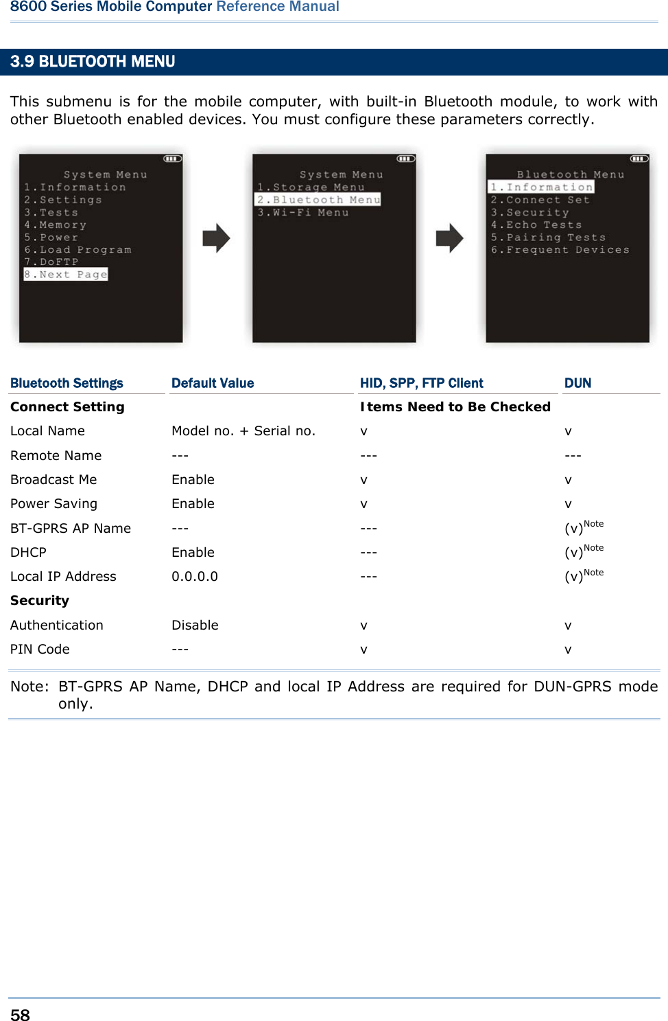
![62 8600 Series Mobile Computer Reference Manual 3.9.4 ECHO TESTS These echo tests are used for verifying connectivity to make sure the mobile computer is within coverage. Press [ESC] to stop and exit the test. SPP: Serial Port Profile It is used for ad hoc networking. DUN: Dial-Up Networking Profile DUN Modem - It makes use of a Bluetooth modem or mobile phone as a wireless modem. DUN GPRS – It makes use of a mobile phone with GPRS functionality and connects to GPRS AP. HID: Human Interface Device Profile It is used for the mobile computer to work as an input device, i.e. keyboard, for a host computer. FTP client: File Transfer Protocol Profile (FTP) It is used for the mobile computer to connect to a file server for file transfer.](https://usermanual.wiki/CipherLab/8600/User-Guide-2140094-Page-74.png)
![65 Chapter 3 System Menu 3.9.5 PAIRING TEST The pairing procedure is for the creation and exchange of a link key between two Bluetooth-enabled devices. The devices use the link key for future authentication when exchanging information. 1) The mobile computer will start with making an inquiry so that the system can generate a list of device(s) that has been discovered nearby. 2) Select a desired target device. For the device name, it can only display a maximum length of 11 characters. When the device name is too long, it will be truncated automatically. 3) Select a Bluetooth service from the “Target Machine” menu. To stop and exit the test, press [ESC]. After pairing successfully, the target device will be added to the Frequent Devices list for quick connection in the future. Note: For the initial use of Bluetooth networking, the pairing procedure must be done before the Echo tests.](https://usermanual.wiki/CipherLab/8600/User-Guide-2140094-Page-77.png)
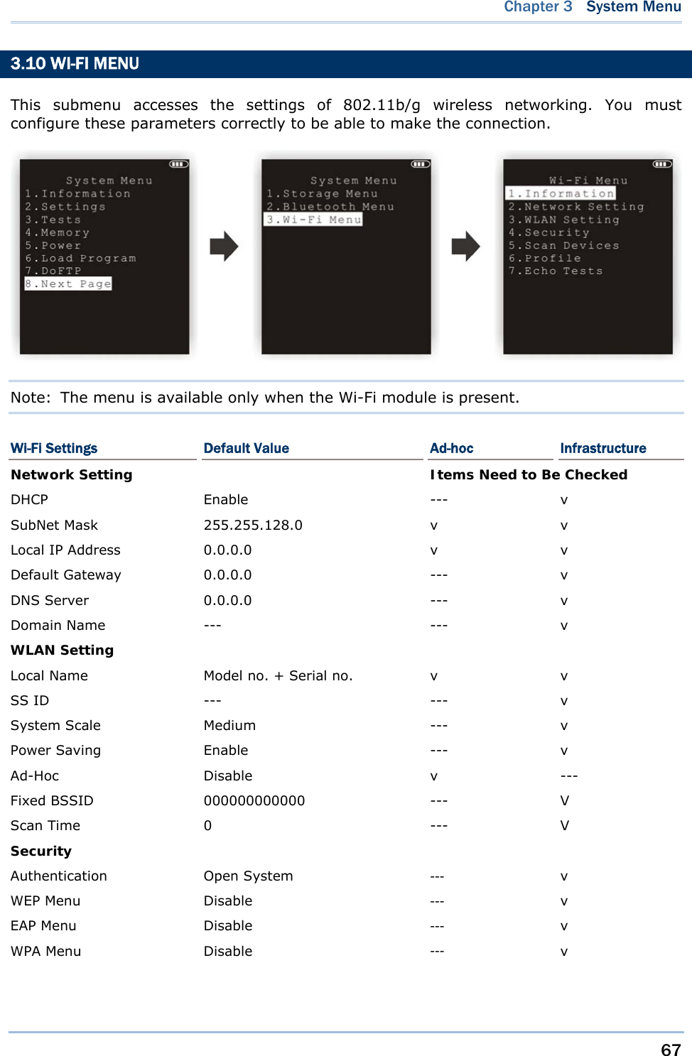
![70 8600 Series Mobile Computer Reference Manual 3.10.3 WLAN SETTING Wireless networking can operate in two modes – (1) Ad-hoc mode: peer-to-peer, and (2) Infrastructure mode: point to multi-point through access points. Set the following parameters. Local Name Enter a name for identifying the mobile computer. By default, it is made up of model number and the serial number. SS ID This refers to Service Set Identifier or AP name, which is used for remote device association. The mobile computer can ONLY communicate with access points that have the same SS ID. System Scale This refers to Access Point Density. Options — [1] Low [2] Medium [3] High [4] Customized The value you set must match that set for the access point. “Low / Medium / High” means the mobile computer will search for other APs only when data transmission rate drops below “1 / 2 / 5” Mbps individually. “Customized” lets you set data rate for the mobile computer to search for other APs when data transmission rate drops below the specified value — 802.11b: 1, 2, 5.5, 11 Mbps 802.11g: 1, 2, 5.5, 11 Mbps & 6, 9, 12, 18, 24, 36, 48, 54 Mbps Power Saving This refers to the low power consumption mode. Options — Enable or Disable The value you set must match that set for the access point. Ad-Hoc This refers to peer-to-peer mode, without going through access points. Options — Enable or Disable](https://usermanual.wiki/CipherLab/8600/User-Guide-2140094-Page-82.png)
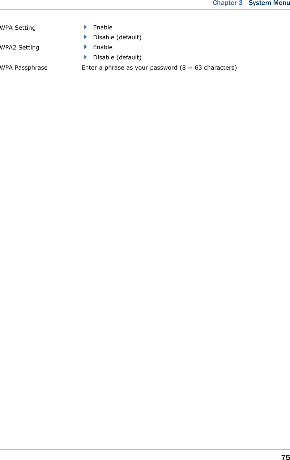
![72 8600 Series Mobile Computer Reference Manual 3.10.4 SECURITY Set or modify security parameters. WEP: Wired Equivalent Privacy EAP: Extensible Authentication Protocol WPA: Wi-Fi Protected Access Authentication [1] Open System [0] Share Key Default authentication type This requires implementing WEP key. WEP Menu WEP Setting Enable (For Share Key, it must be enabled!) Disable (default) WEP Key Length 64 bits 128 bits (default) Default Key WEP KEY1 WEP Key Enter WEP Keys 1 ~ 4 in one of the following input data type: ASCII (up to 13 characters) Hexadecimal (up to 26 characters) EAP Menu (for associating to Cisco access points) EAP Setting Enable Disable (default) EAP ID Enter a user name (up to 32 characters) EAP Password Enter a password (up to 32 characters) WPA Menu (WPA-PSK) WPA Setting Enable Disable (default) WPA2 Setting Enable Disable (default)](https://usermanual.wiki/CipherLab/8600/User-Guide-2140094-Page-84.png)
![74 8600 Series Mobile Computer Reference Manual 3.10.6 PROFILE This function allows users to create up to four Wi-Fi profiles. SSID Enter the SSID (up to 32 characters). Ad-Hoc This refers to peer-to-peer mode, without going through access points. Options — Enable or Disable Authentication [1] Open System [0] Share Key Default authentication type This requires implementing WEP key. WEP Menu WEP Setting Enable (For Share Key, it must be enabled!) Disable (default) WEP Key Length 64 bits 128 bits (default) Default Key WEP KEY1 WEP Key Enter WEP Keys 1 ~ 4 in one of the following input data type: ASCII (up to 13 characters) Hexadecimal (up to 26 characters) EAP Menu (for associating to Cisco access points) EAP Setting Enable Disable (default) EAP ID Enter a user name (up to 32 characters) EAP Password Enter a password (up to 32 characters) WPA Menu (WPA-PSK)](https://usermanual.wiki/CipherLab/8600/User-Guide-2140094-Page-86.png)
![79 This chapter explains Program Manager and Kernel that manage multiple programs and firmware upgrade. IN THIS CHAPTER 4.1 Program Manager ...................................................... 79 4.2 Kernel ...................................................................... 86 4.1 PROGRAM MANAGER The mobile computer supports multiple applications and languages. In the menu of Program Manager, it allows storing up to six programs and has one activated for the current use. If there is no application program exists, Program Manager will be displayed after you turn on the mobile computer. Warning! Program Manager is provided for managing programs in an administrative level. How to access Program Manager? 1) Turn off the mobile computer. 2) Press [8] + [Power]. Chapter 4 PROGRAM MANAGER & KERNEL](https://usermanual.wiki/CipherLab/8600/User-Guide-2140094-Page-91.png)
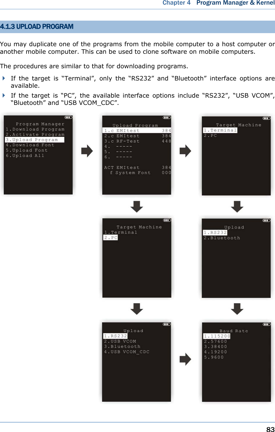
![80 8600 Series Mobile Computer Reference Manual 4.1.1 DOWNLOAD PROGRAM Here provides a list of programs currently stored on the mobile computer with size information. Multiple application programs can be downloaded through a variety of interfaces. Upon completion of downloading, you are allowed to input a name for the program. If there is no need to rename the program, simply press [ENTER] to leave as it is. The length of program name can be up to 12 characters. Program size is in kilobytes. A suffix letter after the memory sector (1 ~ 6) indicates the file type of program. “b” for BASIC program (.SYN) “c” for C program (.SHX) The last line starting with a prefix letter “f” is reserved to display the font file (.SHX) in use on the mobile computer. Note: For a custom font file (.SHX) or a BASIC program (.SYN), it can only be downloaded via System Menu.](https://usermanual.wiki/CipherLab/8600/User-Guide-2140094-Page-92.png)
![81 Chapter 4 Program Manager & KernelSPARE MEMORY SECTORS (1 ~ 6) Additional program files can be directly downloaded to these sectors. Download a program file to an empty sector: 1. Press the arrow keys [Up] and [Down] to select an empty sector, and then press [ENTER]. 2. Select a desired interface for downloading. 3. Connect the interface cable if required, and wait for a few seconds to establish a connection… 4. To abort the action, press [ESC]. Then press [ESC] again to return to the menu. Download a program file to an occupied sector: If no available sectors, you'll have to replace one program with the new one. 1. Press the arrow keys [Up] and [Down] to select a program that you want to delete, and then press [ENTER]. 2. The program information is displayed on the screen. Press the blue key to enter the Alpha mode: Press the capital letter [C] and follow the steps below to download a program file. Press the capital letter [D] if you simply want to delete the program. 3. Select a desired interface for downloading. 4. Connect the interface cable if required, and wait for a few seconds to establish a connection. 5. To abort the action, press [ESC]. Then press [ESC] again to return to the menu. From the menu, you'll see the program has been deleted but no new program is present (because you have canceled the download action). ACTIVE MEMORY SECTOR (“ACT”) Only the application program, which needs to be activated immediately, can be downloaded to the active memory sector. Download to Memory Sector “ACT”: 1. Press the arrow key [Down] to select the memory sector “ACT” (may be unoccupied), and then press [ENTER]. 2. Select a desired interface for downloading. 3. Connect the interface cable if required, and wait for a few seconds to establish a connection. If the active memory sector has already been occupied by an application program, the newly downloaded program will replace the currently active program and come into effect immediately.](https://usermanual.wiki/CipherLab/8600/User-Guide-2140094-Page-93.png)
![82 8600 Series Mobile Computer Reference Manual 4.1.2 ACTIVATE PROGRAM The list shows the entire spare programs stored on the mobile computer. From the list, you can select from the memory sector (1 ~ 6) or SD card. The selected program will be copied to the active memory sector and replace the current one. Note: A font file cannot be activated. TO CLEAR FILE SYSTEM When <New Program Start> screen appears, “Press [ESC] to clear file” means the file system in the SRAM will be cleared out by pressing [ESC]. Then there will be no data (transactions, settings, etc.) stored on the mobile computer when the new program comes into effect. TO KEEP FILE SYSTEM To keep the data, simply press any other key.](https://usermanual.wiki/CipherLab/8600/User-Guide-2140094-Page-94.png)
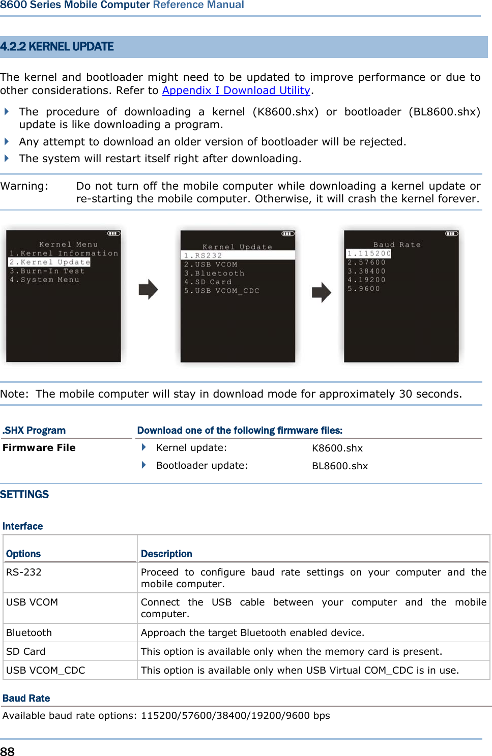
![86 8600 Series Mobile Computer Reference Manual 4.2 KERNEL The kernel resides in the innermost core of the system. It has the highest security and is always protected by the system. When the application program is corrupted and System Menu fails at the same time, Kernel Menu provides an access to fix the system. Warning! Kernel Menu is NOT for the use of any end users. How to access Kernel Menu? 1) When the last session is in System Menu or Program Manager, simply turn off the mobile computer. Otherwise, you must reload the battery pack. 2) Press [1] + [7] + [Power].](https://usermanual.wiki/CipherLab/8600/User-Guide-2140094-Page-98.png)

![89 Chapter 4 Program Manager & Kernel KERNEL UPDATE VIA BLUETOOTH 1) Go to Kernel Menu | 4. System Menu | 8. Next Page | 2. Bluetooth Menu | 3. Security, and configure the following Bluetooth settings first. Authentication PIN code 2) Go to Kernel Menu | 2. Kernel Update and select Bluetooth. 3) Start the pairing procedure from your computer, for example, click [Pair Device] and/or [Connect Bluetooth Serial Port]. 4) Run the download utility: ProgLoad.exe - Select interface RS-232 for using Bluetooth SPP. - Select COM port properties that match with the serial port settings used on your computer. KERNEL UPDATE VIA SD CARD 1) If you have copied the desired program file(s) to your SD card, go to Kernel Menu | 2. Kernel Update and select SD Card. You will see a list of all the files under the directory “\Program”, as shown above. 2) Press the arrow keys [Up] and [Down] to select a file. 3) Press [ENTER] to view information of the program file. Press the arrow keys to select a file. Then, press [ENTER] to view information of the program file.](https://usermanual.wiki/CipherLab/8600/User-Guide-2140094-Page-101.png)
![90 8600 Series Mobile Computer Reference Manual 4) Press [ENTER] to confirm downloading the program file to the mobile computer. Press [ESC] to abort the download task. 4.2.3 BURN-IN TEST This tool is provided for manufacturing use. Warning! You should not perform this test. 4.2.4 SYSTEM MENU Refer to System Menu for details. This submenu is the same as System Menu for system configuration.](https://usermanual.wiki/CipherLab/8600/User-Guide-2140094-Page-102.png)