CipherLab 8770 Mobile Computer User Manual 8700 Series Mobile Computer
CipherLab Co., Ltd. Mobile Computer 8700 Series Mobile Computer
UserManual.wiki
>
CipherLab
>
8770 User Manual
>
User Manual 1 of 2
Contents
1.
User Manual 1 of 2
2.
User Manual 2 of 2
3.
Users Manual- 1 of 2
4.
Users Manual- 2 of 2
5.
Users Manual 1 of 2
6.
Users Manual 2 of 2
User Manual 1 of 2
Navigation menu
Upload a User Manual
Namespaces
Wiki Guide
HTML
PDF
Info
Views
User Manual
Discussion / Help
Navigation
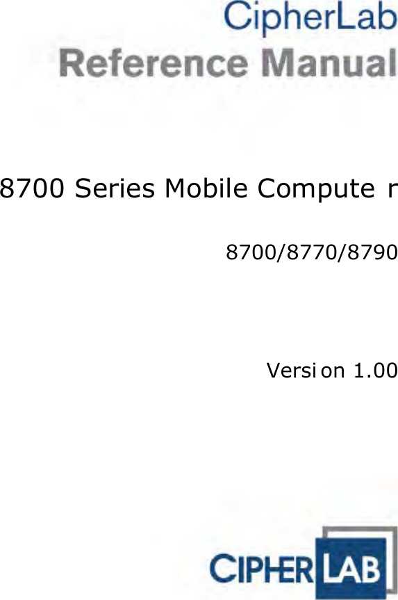

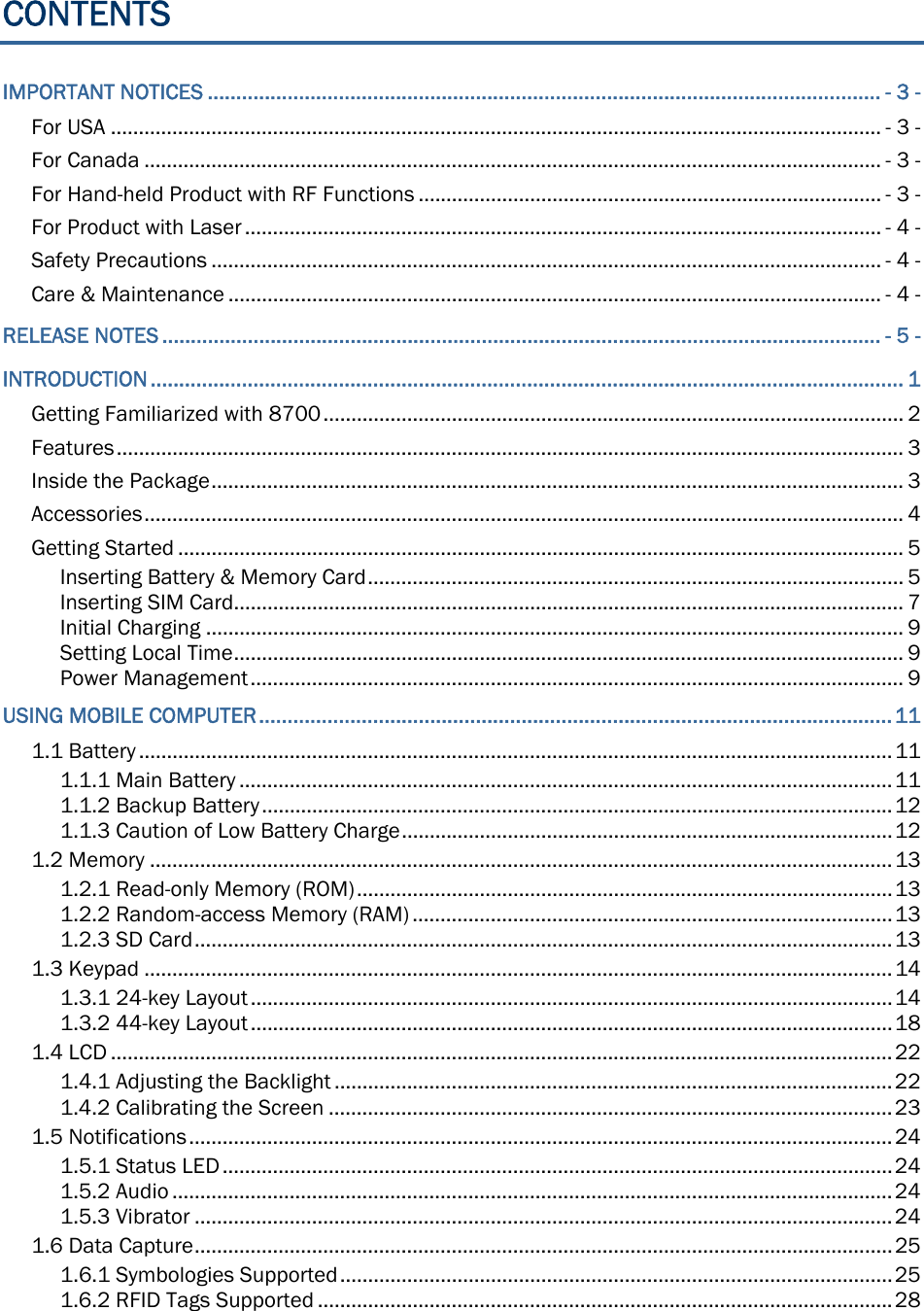
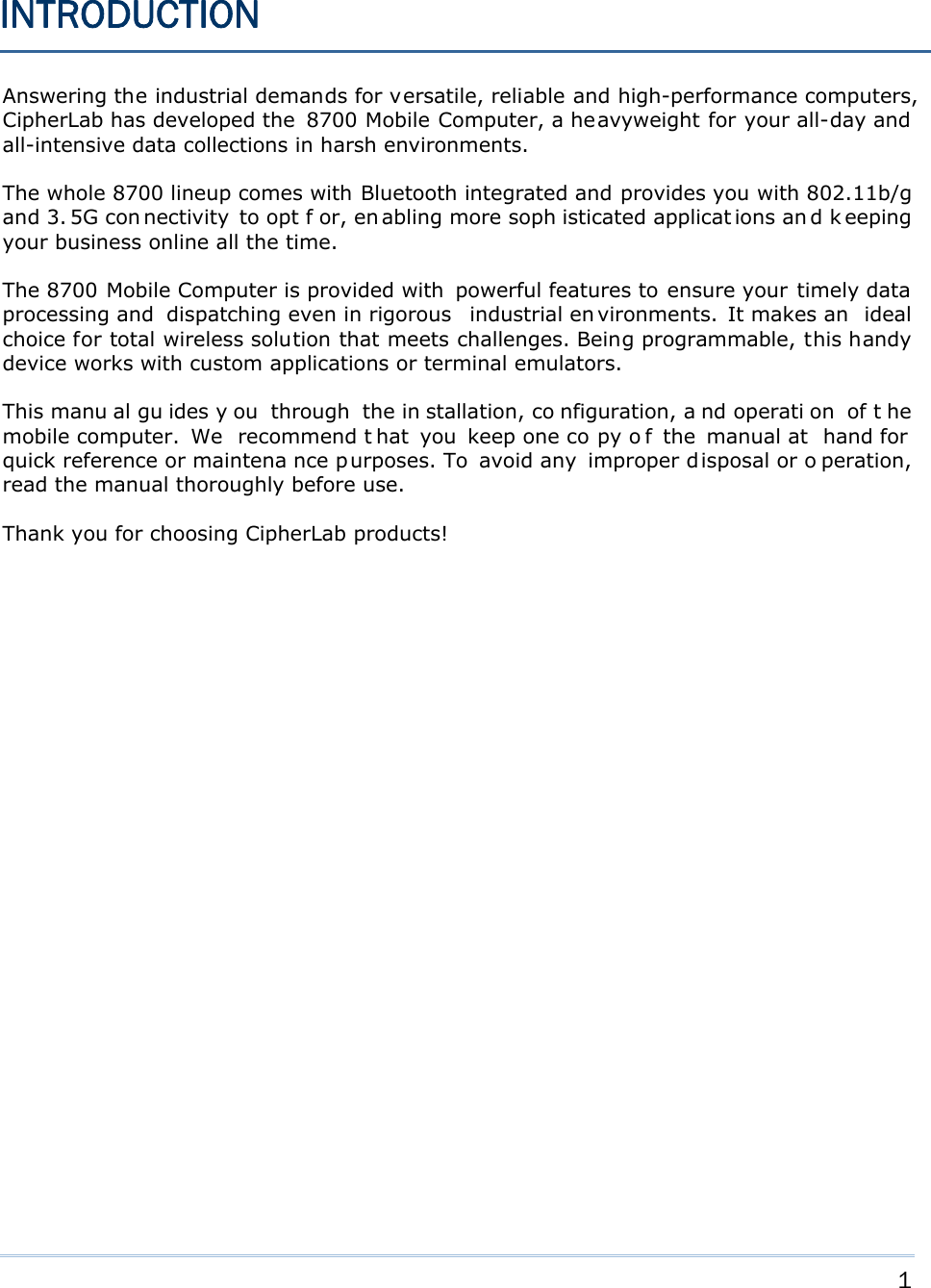

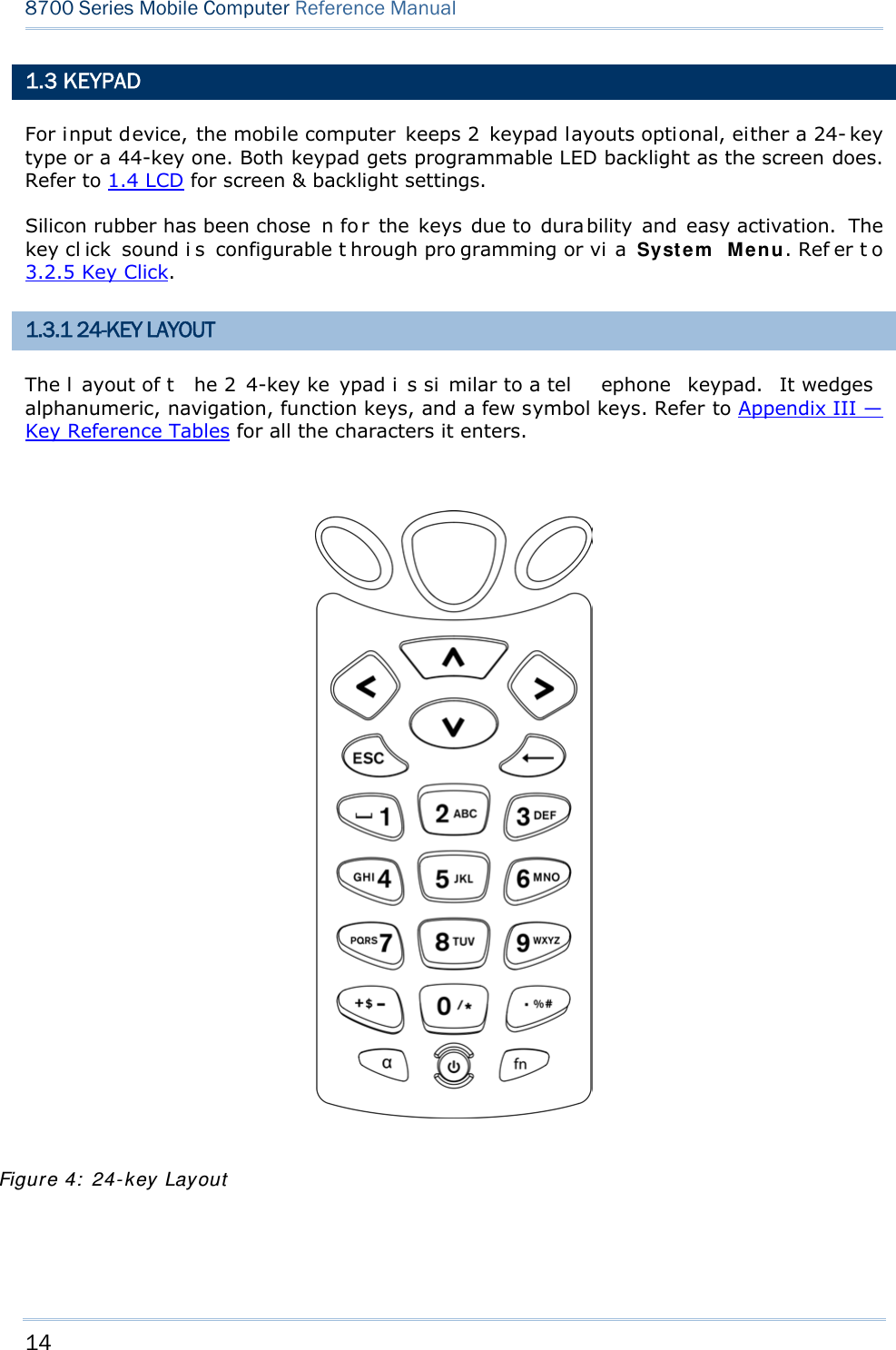
![15 Chapter 1 Using mobile computer This 24-key alphanumeric keypad enters num bers by default. The ke ypad’s alphabet key switches the keypad to al phabetic input. A few sy mbols are supp orted when the keypad sits in alphabetic input, whether uppercase or lowercase. Press the [α] key (repeatedly) until the mob ile computer shows a n “ A”, whi ch we might as well call “the alphabet icon”, at the lower-left of the screen. The keypad starts to enter all caps and a few symbols without holding down the [α] key. Press the [α] key (repeatedly) until the mo bile computer shows a n “a”, whi ch we might as well call “the alphabet icon”, at the lower-left of the screen. The keypad starts to enter all lowercase letters and a few symbols without holding down the [α] key. Note the letter case doesn’t impact the symbols. An overview of the alphabet icons and the keypad’s input mode: Alphabet Icons Keypad’s Input Mode None Numbers, hyphen minus “-”, and dot “.” A All uppercase letters and symbols a All lowercase letters and symbols When inputting alph abetic characters, the l etters and the number printed on a k ey take turn to show where the cursor is when you keep pressing that key; each press must not exceed one second. Fo r example, when you keep press the num ber key [2], the letters “A”, “B”, “C” and the number “2” take turn to show for uppercase while “a”, “b”, “c” and “2” will take turn to show for lowercase. When you first press the number key [2], the letter “A” or “a” is produced. When yo u press the n umber key [2] t wice (t he ti me i nterval must not exceed one second), the letter “B” or “b” is produced. When yo u press the number key [2] three times (the ti me i nterval between each press must not exceed one second), the letter “C” or “c” is produced. When you press the number key [2] four times (the time interval between each press must not exceed one second), the number “2” is produced. In order to get the desired character, you ne ed to press the same key one to four times (the time interval between each press must not exceed one seco nd). Only when the pressing stops for longer than one second or another key is pressed will the system send out the due key code or change over to send another key code to the active application program. The [f n] key is pressed with a nu mber key . Upon you r pressing [f n] k ey, it s associated icon F displays at the bottom-left of the screen of the mobile computer. Press the second key, sa y [ 5], to com plete the key combi nation and pr oduce [F5] fu nction. Then the icon F goes off automatically.](https://usermanual.wiki/CipherLab/8770.User-Manual-1-of-2/User-Guide-1646570-Page-25.png)
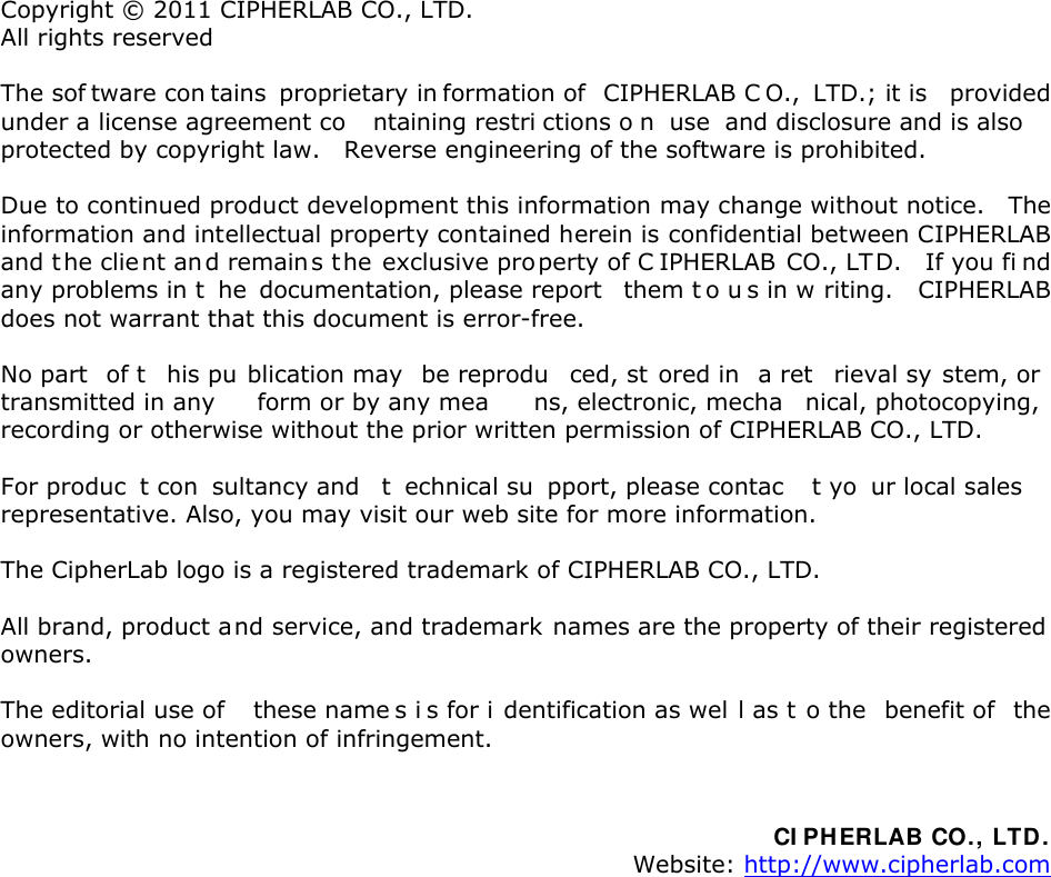
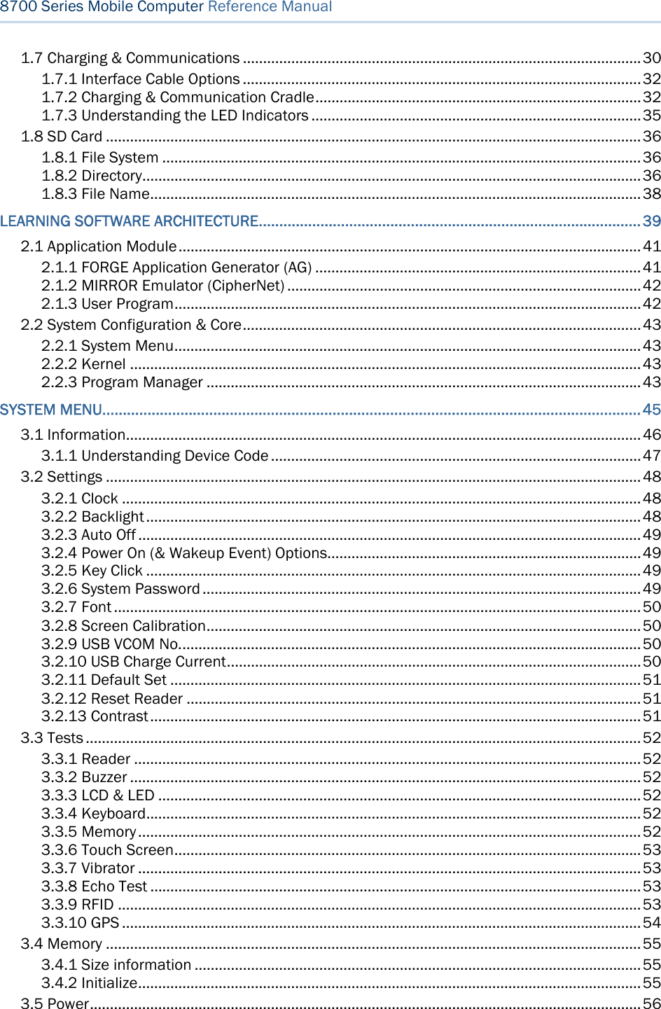
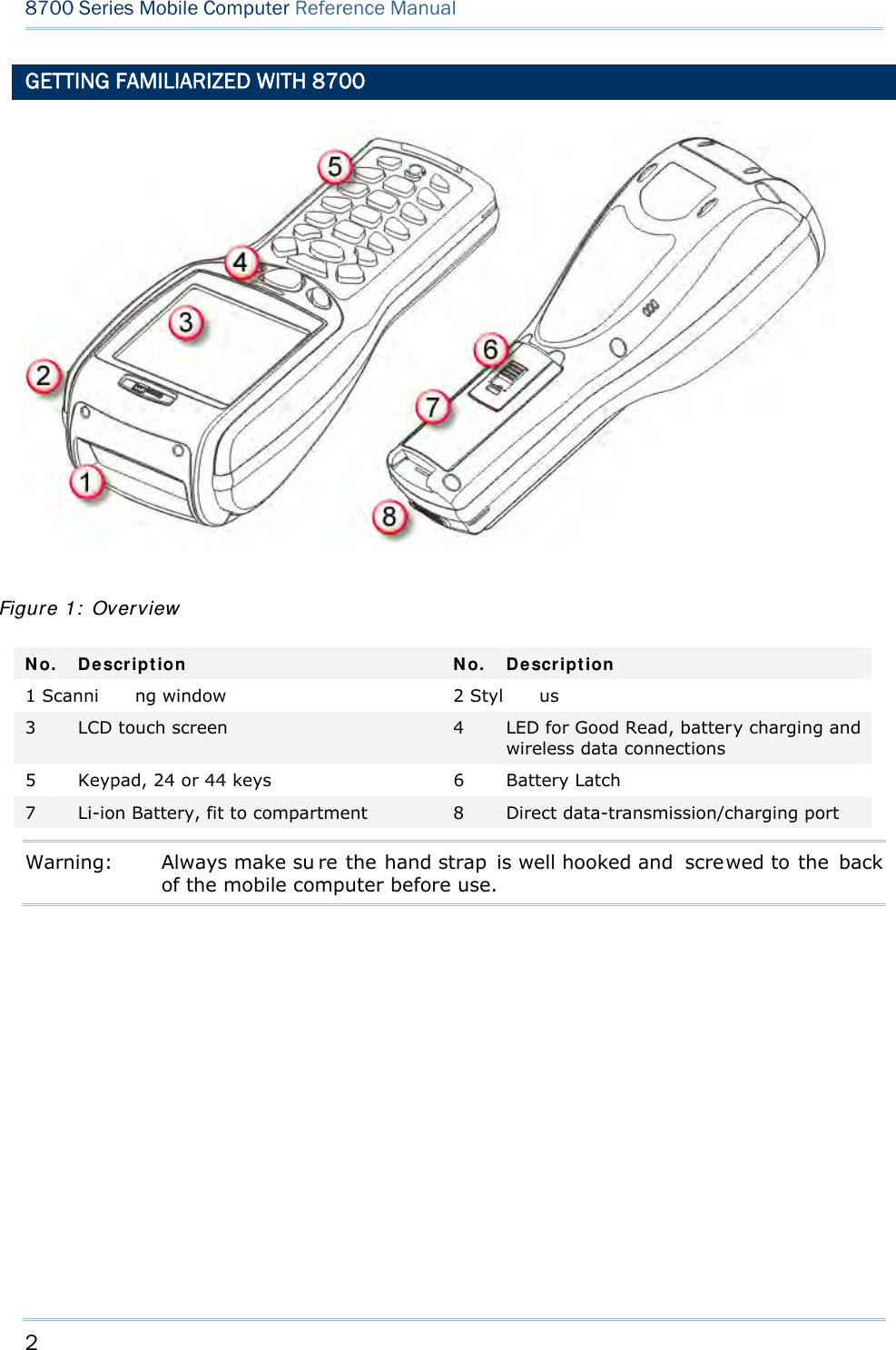
![16 8700 Series Mobile Computer Reference Manual Functions of the common keys are briefly described as below: SCAN Triggers the scan engine so it reads a barcode when reader function is enabled. ENTER The two [Ent er] keys on both si des of the [S CAN] key are use r-friendly and convenient for both right-handed and left-handed operators. Both keys execute commands or confirm input. Press the [fn] key the pre ss either of these [Enter] keys to turn on/off the backlight for the LCD and keypad. Navigation Keys These keys move the cursor left, up, down, or right. Press the [fn] key then p ress ei ther of up/down key to decrease/increase LCD contrast. Press th e [fn ] key then p ress ei ther o f l eft/right key to decrease/increase the LCD backlight brightness. ESC (Escape) Stops and quits the current operation. ← (Backspace) Deletes the precedi ng character where the cursor is. If this key is pressed and held, a clear code is sent. α (Alphabet Key) This key is a modif ier k ey that requ ires a second key pressed to get th e yellow-engraved letters (A~Z) and symbols. Icon Description A This icon appears a t t he lo wer-left o f t he s creen to in dicate keypad set to enters all uppercase letters and symbols. a This icon appears a t t he lo wer-left o f t he s creen to in dicate the keypad set to enters all lowercase letters and symbols.](https://usermanual.wiki/CipherLab/8770.User-Manual-1-of-2/User-Guide-1646570-Page-26.png)
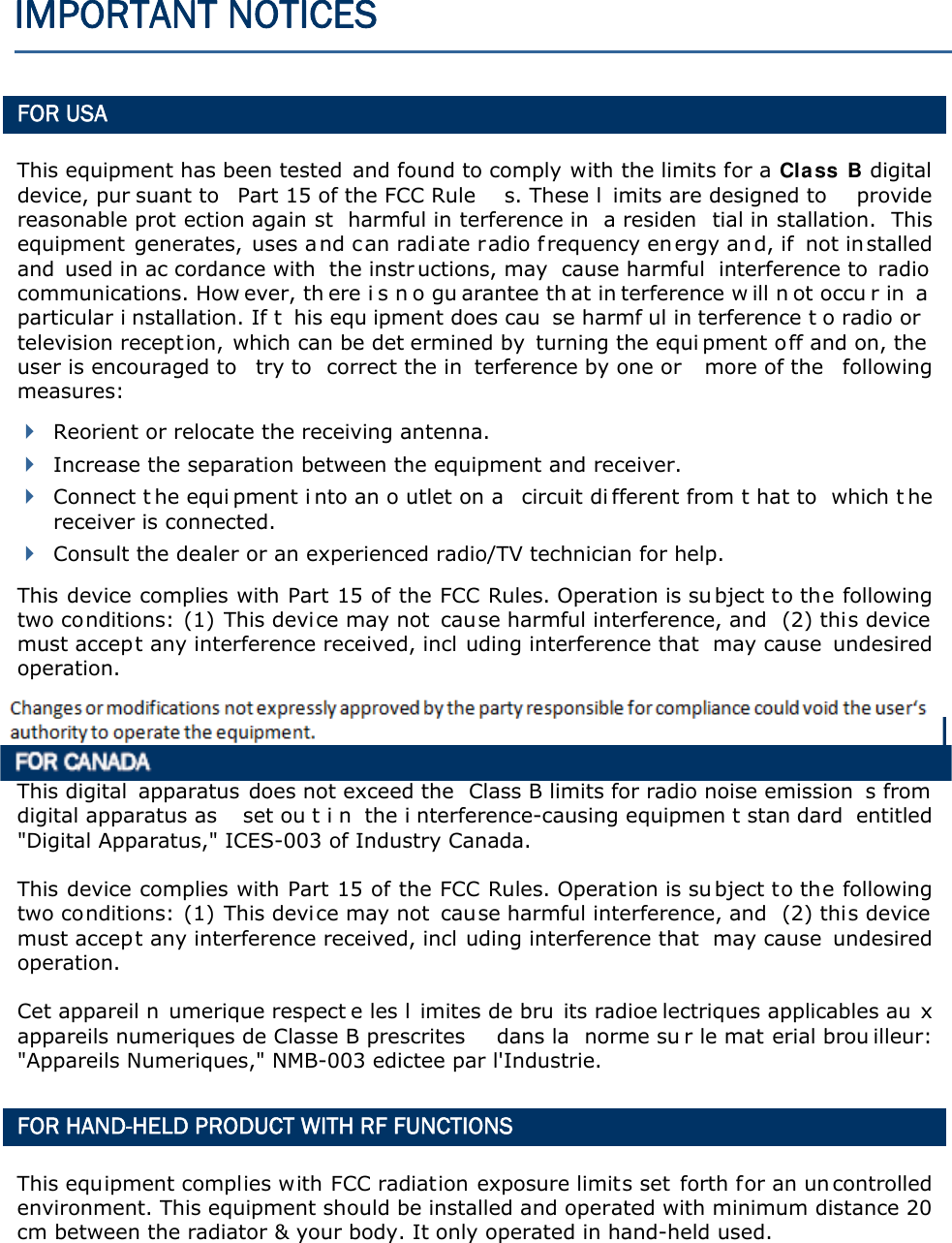
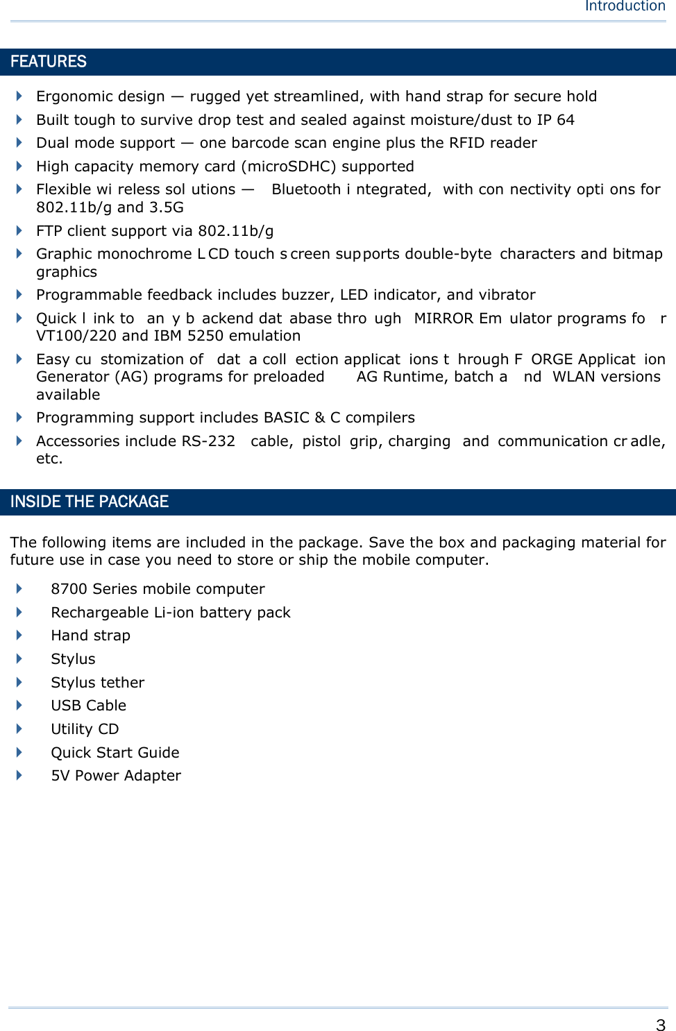
![17 Chapter 1 Using mobile computer fn (Function Key) This key is a modif ier ke y that requir es a second key ([0] ~ [ 9]) pressed to deliver the value of key combination. Icon Description F In default state, the functi on toggl e i s set to “Auto Resume” and operates as described below: This icon appears when you press the function key [fn], indicating the keypad s et to the functi on key input. Press a second key to get the desired function. Once the second key is pressed, the icon goes off automatically. POWER Key In order to prevent an ac cidental press of the PO WER key, you need to press and hold this key for approxi mately 1.5 seconds to turn on/ off the mobil e computer. Note: (1) Fu nctionality of keys i s appli cation-dependent. The system will send the associated key code to the application pr ogram, an d it is u p t o t he applicat ion program to interpret the key code. (2) As long as a status icon appears on the screen, it indicates a certain mode has been activated and it isn’t necessary to hold the modifier key.](https://usermanual.wiki/CipherLab/8770.User-Manual-1-of-2/User-Guide-1646570-Page-27.png)
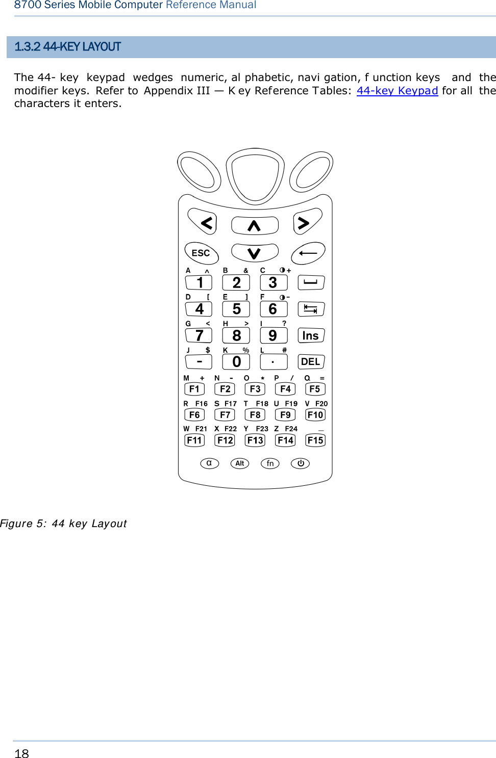
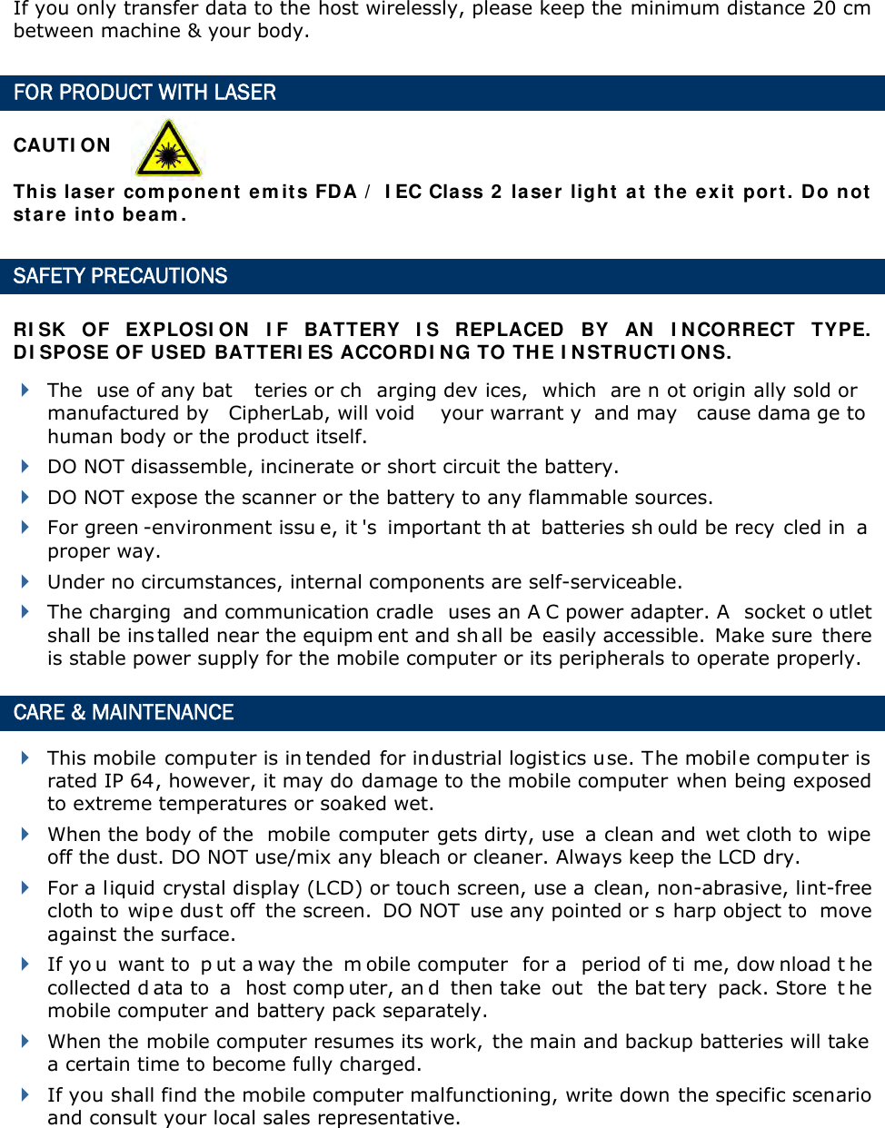
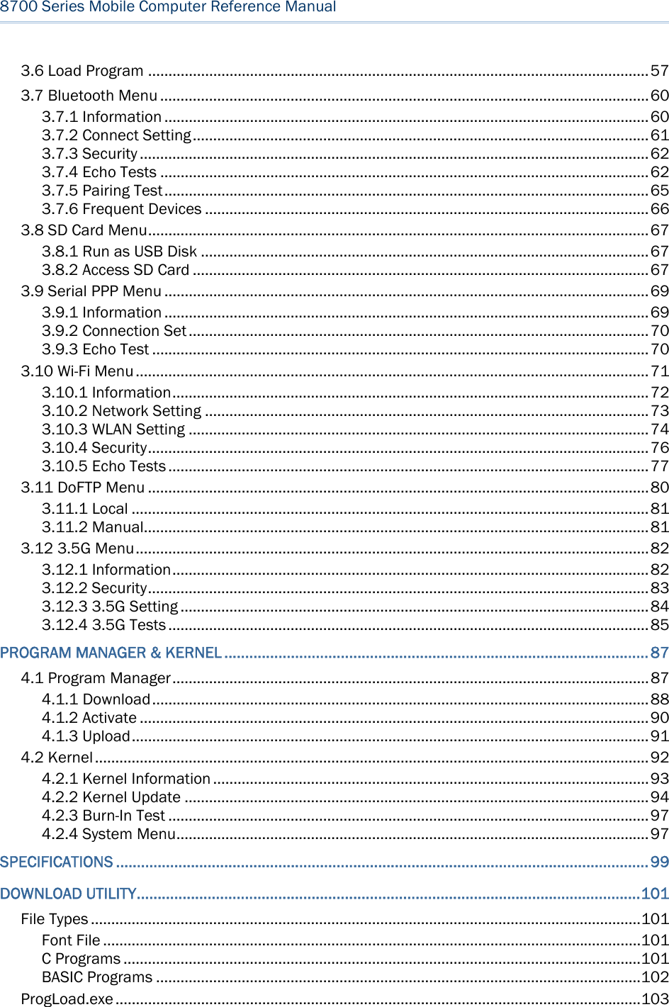
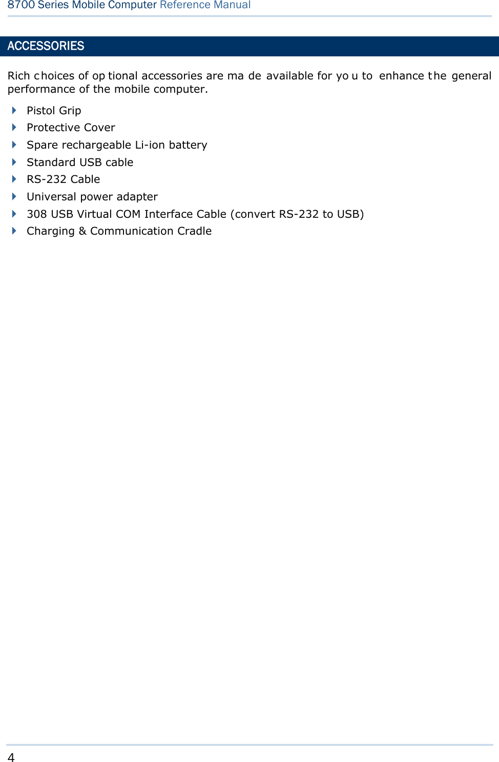
![19 Chapter 1 Using mobile computer In default state, this 44-key alphanumeric keypad enters numbers and launches the functions of F1 through F15. THE [ALPHA] KEY Press the blue modifier key [ α] to toggle the keypad among numeric, uppercase alphabetic, and lowercase alphabetic modes. Press the [ α] key (repeatedly) until the mob ile computer shows an “ A”, whi ch we might as well call the “alphabet icon”, at the lower-left of the screen. The keypad starts to enter all uppercase letters without the need to hold down the [α] key. Press the [ α] key (repeatedly) until the mobile co mputer shows an “ a”, wh ich we might as well call the “alphabet icon”, at the lower-left of the screen. The keypad starts to enter all lowercase letters without the need to hold down the [α] key. An overview of the alphabet icons and the keypad’s input modes: Alphabet Icons Keypad’s Input Mode None Enters numbers, hyphen minus “-”, and dot “.” Launches F1 through F15. A All uppercase letters a All lowercase letters THE [FN] KEY The orange [fn] key makes the ke ypad enter the orange-engraved characters. After the [fn] key is pressed, it requires you to press a second key to complete the action. Here are the basi cs how this [fn] key works: You first press the orange [fn] key and see an ico n F sh ows at th e low er-left of th e screen. T hen you press another ke y engraved with an orange-colored character/graphic to produce the following: 1) Entering that orange-colored character (mostly symbols). 2) Launching the functions of F16 through F24. 3) Increasing/decreasing backlight brightness for the screen and the keypad. The [fn] ke y i s set to “Auto Resu me” by de fault, which mean s the [ fn] k ey is en abled once pressed, and becomes disabled once the second key is pressed. Here’s an example how you produce the function of [F16]: 1) Press the orange [fn] key . The mobile computer’s screen shows an F at the lower-left of the screen. 2) Press the key [F6], which is engraved with the orange-colored “F16”. The system produces the function of [F16]. The icon F goes off.](https://usermanual.wiki/CipherLab/8770.User-Manual-1-of-2/User-Guide-1646570-Page-29.png)
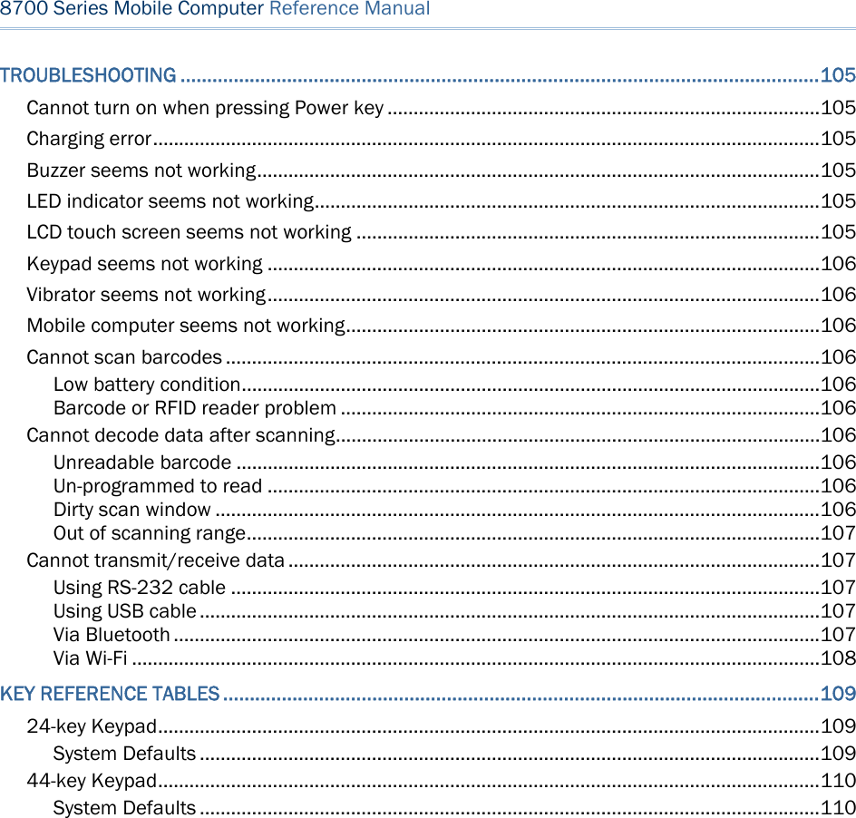
![20 8700 Series Mobile Computer Reference Manual Functions of the common keys are briefly described as below. SCAN Triggers the scan engi ne so i t reads a barcod e when the re ader functi on i s enabled. ENTER The two [Ent er] keys on both si des of the [S CAN] key are use r-friendly and convenient for both right-handed and left-handed operators. Both of them execute commands or confirm input. Press the [fn] key then press either of these [Enter] keys to turn on/off the backlight of LCD and keypad. Navigation Keys These keys move the cursor left, up, down, or right. Press the [fn] key then p ress ei ther of up/down key to decrease/increase LCD contrast. Press th e [fn ] key then p ress ei ther o f l eft/right key to decrease/increase the LCD backlight brightness. ESC (Escape) Stops and quits the current operation. ← (Backspace) Deletes the p receding character where the cursor i s. If thi s key is pressed and held, a clear code is sent. 9 (Space) Inserts a blank space at the position where the cursor is. ) (Tab) Moves the cursor to the next tab stop. Ins (Insert) Switches the keypad between the overtype mode and insert mode. This key is helpful when the mobile computer is working on terminal emulation. In overtype mode, when you are typi ng, the curs or overwri tes any character that is right after its current position. In insert mode, when you are typi ng, the cursor inserts a character at its current position. DEL (Delete) Deletes the character at the back of the cursor.](https://usermanual.wiki/CipherLab/8770.User-Manual-1-of-2/User-Guide-1646570-Page-30.png)
![21 Chapter 1 Using mobile computer α (Alphabet Key) This key is a modif ier key that requ ires a second key presse d to produce the blue-engraved letters (A~Z). Icon Description A This icon appears at t he lo wer-left o f t he s creen t o in dicate ke ypad set to enter all uppercase letters. a This icon appears at t he lo wer-left o f t he s creen t o in dicate ke ypad set to enter all lowercase letters. Alt Key This key is a modif ier key that alters the next key pressed. The functiona lity depends on the application that is active at the moment. Icon Description A This icon a ppears wh en yo u p ress [ Alt] to enter the special function mode. fn (Function Key) This key is a modif ier k ey that requ ires a second key pressed to enter the orange-engraved characters (mostly symbols) and produce the function of F16 through F24. Icon Description F The function toggle is set to “Auto Resume” by default which operates as described below: This i con ap pears when you press th e orange mo difier key [fn], indicating the keypad set to func tion key input. Then you press a second key to enter the desi red symbol s or produce the desired function. Once the second key is presse d, the icon F goes off automatically. Power Key In order to p revent an ac cidental press of the PO WER key, you need to pr ess and hold down this key for approximately 1.5 seconds to turn on/off the mobile computer. Note: (1) Functionality of key s is applicat ion-dependent. T he sy stem will sen d th e associated key code to the a pplication pr ogram, an d it is u p t o the applicat ion program to interpret the key code. (2) Wh en a st atus icon appears on th e low er-left of the screen, it in dicates a certain mode is activated and it is not necessary to hold down the modifier key.](https://usermanual.wiki/CipherLab/8770.User-Manual-1-of-2/User-Guide-1646570-Page-31.png)
![22 8700 Series Mobile Computer Reference Manual 1.4 LCD The mobile computer ships with a 3” FSTN graphic LCD, 160 by 16 0 pixels res olutions, which can be programmed to display text or graphics such as specific font and company logo to meet various applications. Options Font Size (pixels) Characters by lines English font Font size 6×8 (pixels) Font size 8×16 (pixels) 26 characters by 19 lines 20 characters by 9 lines Chinese font Font size 12×12 (pixels) Font size 16×16 (pixels) 13 characters by 12 lines 10 characters by 9 lines Other language fonts, company logo… Programmable Note: The bot tom lin e ( ICON_ZONE) is reserved t o display st atus icon s, su ch as th e battery icon. 1.4.1 ADJUSTING THE BACKLIGHT The backl ight of s creen and keypad makes i t easier to operate the mobile computer in dim envi ronments. By pressi ng t he fol lowing key com binations, L CD ba cklight ca n be turned o n/off a nd t he brightness can be adj usted. Kee p pressing the key co mbination until the br ightness or contras t d ecreases or increases to a desired level. Alt ernatively the brightness and contrast are controllable through programming or via System Menu. Refer to 3.2.2 Backlight and 3.2.13 Contrast. Note: Using back light on batt ery pow er w ill su bstantially redu ce bat tery pow er. We suggest th at y ou dim the back light while work ing in a w ell-lit area or set it to automatic power off when the computer isn’t actively used. Use the following key combinations to adjust the backlight for the mobile computer’s LCD and keypad, and also the contrast for the LC D. Combine the keys by pressing the [fn] key first and then pressing the second key. Key Combination Action 24-key 44 key + [Enter] + [Enter] Toggles on/off the backlight + [Up] + [Up] Increases the contrast of LCD + [Down] + [Down] Decreases the contrast of LCD + [Right] + [Right] Turns on the backl ight a nd i ncreases the bri ghtness of LCD/keypad backlight. + [Left] + [Left] Turns on the backl ight and decr ease the bri ghtness of LCD/keypad backlight. + [3] Same as + [Up]](https://usermanual.wiki/CipherLab/8770.User-Manual-1-of-2/User-Guide-1646570-Page-32.png)
![23 Chapter 1 Using mobile computer + [6] Same as + [Down] 1.4.2 CALIBRATING THE SCREEN This LC D i s a touc h s creen that supports to uch control by a stylus. It also f eatures signature c apture so signatures can be saved to serve as receipt confirmation whe n goods are delivered to door. Refer to 3.2.8 Screen Calibration for screen calibration. Warning: DO NOT contact the screen surface with any pointed or sharp object.](https://usermanual.wiki/CipherLab/8770.User-Manual-1-of-2/User-Guide-1646570-Page-33.png)
![24 8700 Series Mobile Computer Reference Manual 1.5 NOTIFICATIONS 1.5.1 STATUS LED A LED indic ator is recessed above the [SCAN ] button. It presents d ual modes and each mode presents dual colors. This LED indicator can be programmed to provide information that helps di agnosing the stat us of the mobile computer. For exampl e, i f you are usi ng AG Ru ntime, y ou w ill b e in formed of t he scann ing resu lt immediately. LE D1 is u sed f or "Good Read" and will become solid green upon reading a barcode successfully. LED1 provides the information on the charging status and barcode reading. LED2 provides the information on wireless communications. LED1: Red/Green Red Green User Power ON User definable User definable Solid green for Good Re ad by default Power Off, B attery Charging System default Flashing red: Charging System default Flashing green: Charging done Charging Error System default Flashing red and green: Charging error occurs LED2: Blue/Green Blue Green Bluetooth System default Flashing b lue, q uickly: W aiting fo r connection or connecting Flashing blue, slowly: Connected --- Wi-Fi --- System default Flashing g reen, q uickly: Waiting for connection or connecting Flashing green, sl owly: Connected 1.5.2 AUDIO The mobile computer has a low power transd ucer type buzzer that is programmable for status feed back. I n pa rticular, its freque ncy and duration can be programmed for the alert of Good Read in the provided terminal emulation programs. 1.5.3 VIBRATOR The mobile compu ter is integrated with a vibrator t hat is programmable f or status feedback. It mak es t he mobi le co mputer applicable t o w ork in noisy environments. In particular, the vibrator can be programmed fo r the alert of Good Read in the provided terminal emulation programs.](https://usermanual.wiki/CipherLab/8770.User-Manual-1-of-2/User-Guide-1646570-Page-34.png)
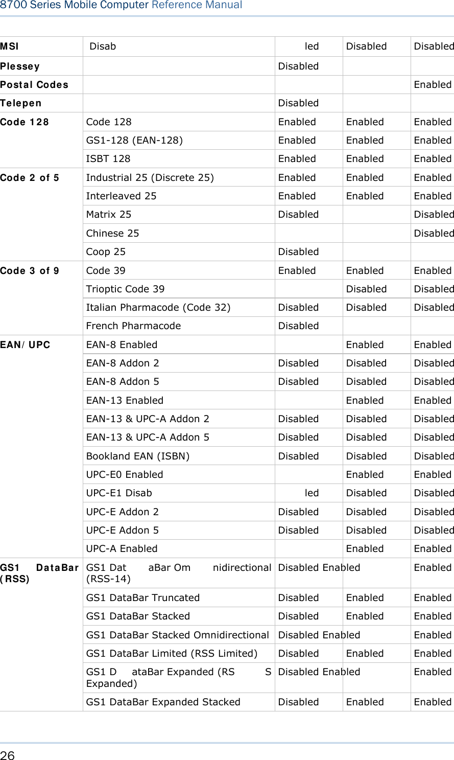
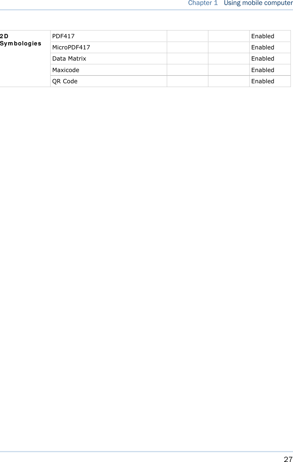
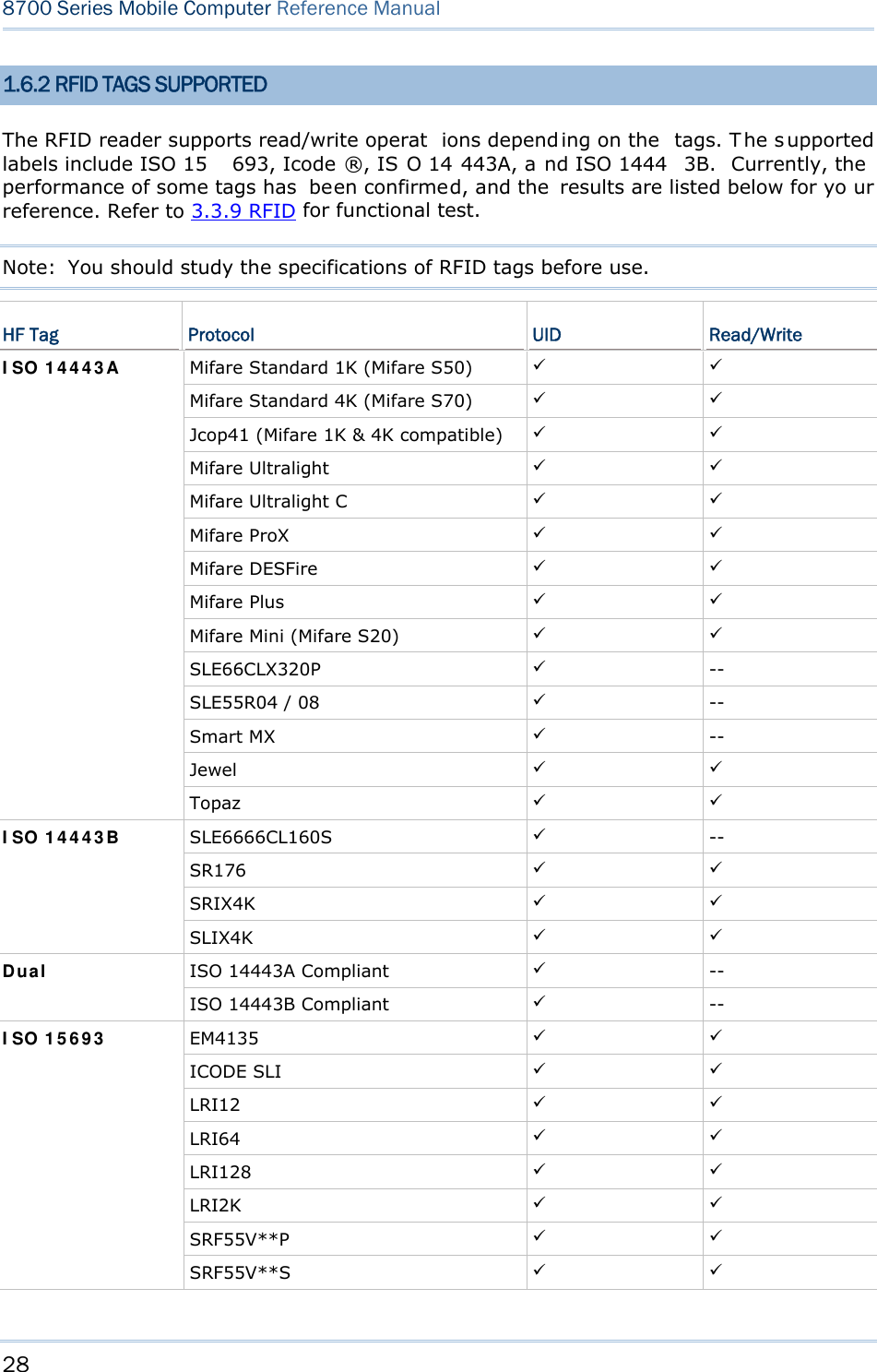
![25 Chapter 1 Using mobile computer 1.6 DATA CAPTURE Options of different reader combination ar e supported including 1D+RFID and 2D+RFID. For each combination, both readers can be initialized and ready for scanning at the same time (dual mode operation). For example, if you press the [SCAN] trigger while running the preloaded AG runtime on the mobile computer, it will read a barcode in position or an RFID tag in proximity depending on which one comes first. Note: You can not have 1D +2D scan e ngines i nstalled on the mobile computer because they are both barcode readers. Varying by the reader type installed, the supported sym bologies or tag types a re listed below: 1D CCD scan engine 1D Laser scan engine 1D Long Range Laser scan engine (LR) 2D scan engine RFID reader 1.6.1 SYMBOLOGIES SUPPORTED A w ide v ariety of scan en gines is av ailable f or deliv ering f lexibility t o meet dif ferent requirements. Depending on the scan engine integrated, the mobile computer is capable of scanning barcodes of a number of symbol ogies that are enabled by defa ult while running the preloaded AG runtime. Refer to 3.3.1 Reader for functional test. If you need to scan barcodes that are encoded in a symbology that is disabled by default in AG run time, FORGE Application Generator ( ForgeAG.exe) ca n help you configure symbology settings and reader settings. First, ena ble the desired symbolog ies in FORGE Application Generator, and then do wnload the appl ication setti ngs to the mobi le computer. Note: In AG or C ipherNet run time, n ot all of the symbologies are enabled by defa ult. Instead of running any of them, you can develop your own applications to control the scan engine for data collection. For d etails on c onfiguring reader and symbology settings, please refer to the documentation of the software you use. Symbologies Supported (Default Setting: Enable/Disable) CCD/Laser LR 2D Codabar Enabled Enabled Enabled Code 11 Disab led Disabled Code 93 Enabled Enabled Enabled CC-A/B Disabled CC-C Disabled Composite Code TCIF Linked Code 39 Enabled](https://usermanual.wiki/CipherLab/8770.User-Manual-1-of-2/User-Guide-1646570-Page-35.png)
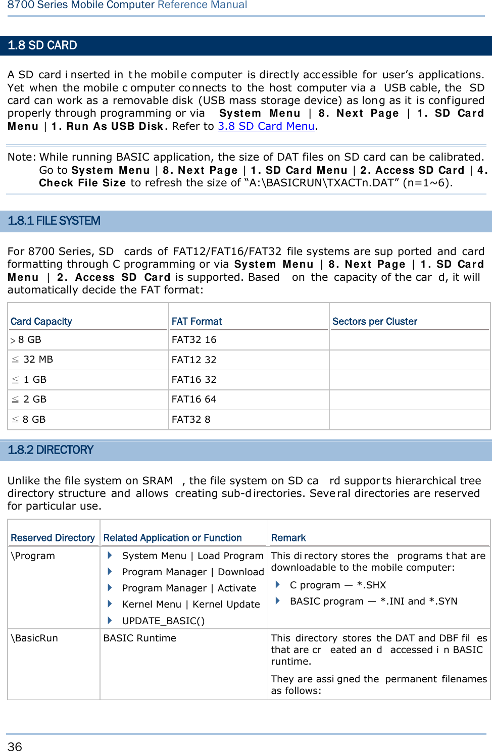
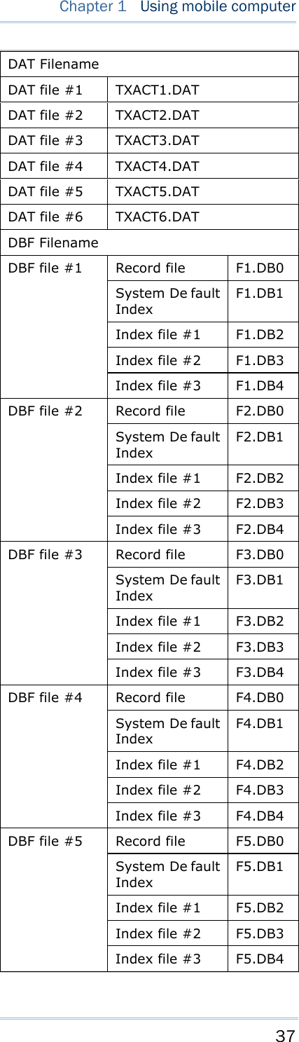
![38 8700 Series Mobile Computer Reference Manual \AG\DBF \AG\DAT \AG\EXPORT \AG\IMPORT Application Generator (a.k.a. AG) This di rectory stores the DAT, DBF, and Lookup fil es that are created and/or accessed in Application Generator. 1.8.3 FILE NAME A f ile n ame mu st follow 8. 3 f ormat ( = sh ort filenames) — at most 8 c haracters for filename, and at most three characters for f ilename extension. The following characters are unacceptable: “ * + , : ; < = > ? | [ ] On 8700 Series, it can only display a filename of 1 ~ 8 characters (the null character not in cluded), and f ilename ex tension w ill b e display ed if prov ided. If a f ile n ame specified is longer than eight characters, it will be truncated to eight characters. Long filenames, at most 255 characters, are allowed when using the mobile computer equipped with SD card as a mass storag e devi ce. For exampl e, you may ha ve a filename “123456789.txt” created from yo ur PC. However, whe n the same file is directly ac cessed on the mobile computer, the filename wi ll be tru ncated to “123456~1.txt”. If a file name is not specified in ASCII characters, in order for the mobile computer to display it c orrectly, y ou may n eed t o dow nload a mat ching f ont f ile t o t he mobile computer first. The file name is not case-sensitive.](https://usermanual.wiki/CipherLab/8770.User-Manual-1-of-2/User-Guide-1646570-Page-48.png)
![39 This chap ter describes the softwar e preinsta lled on the mobile computer — the Kernel, System, and Application, and each has its own function menu. When a menu displays, select an item by either of the following ways: Press t he navigation k eys [Up ] a nd [Down] to move be tween the menu items and press [Enter] to select one. Press the number key that corresponds to the menu item to select it. Use a stylus to tap an item from the menu to select it. Follow the on-screen instructions to cha nge a setti ng, or press [ ESC] to return to a previous page or menu. Chapter 2 LEARNING SOFTWARE ARCHITECTURE](https://usermanual.wiki/CipherLab/8770.User-Manual-1-of-2/User-Guide-1646570-Page-49.png)
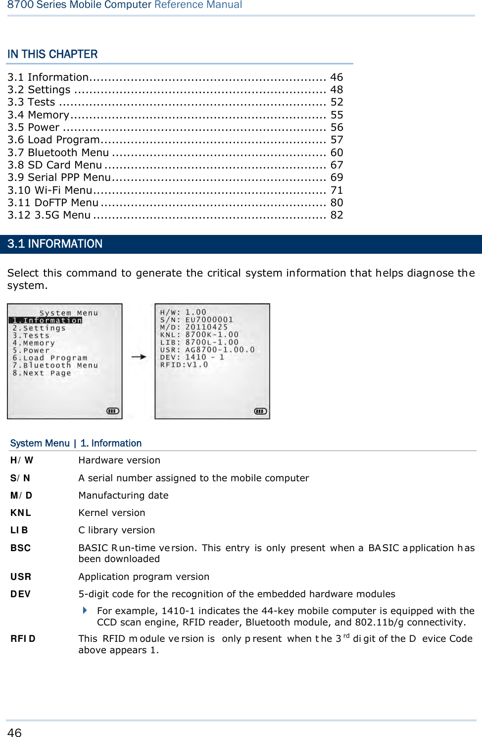
![40 8700 Series Mobile Computer Reference Manual On each screen, the bottom line displays status icons, such as: The 4-bar battery icon indicates the current power status. The status icon of input mode is controlled by the modifier key: or The status icon of function mode is controlled by the modifier key: or The turn-page icon ( ) indicates there is a previous page or menu. To return to a previous page or menu, yo u may press [ESC], touch the menu title, or follow the on-screen instructions. IN THIS CHAPTER 2.1 Application Module ..................................................... 41 2.2 System Configuration & Core....................................... 43 Figure 9: Software Architecture](https://usermanual.wiki/CipherLab/8770.User-Manual-1-of-2/User-Guide-1646570-Page-50.png)
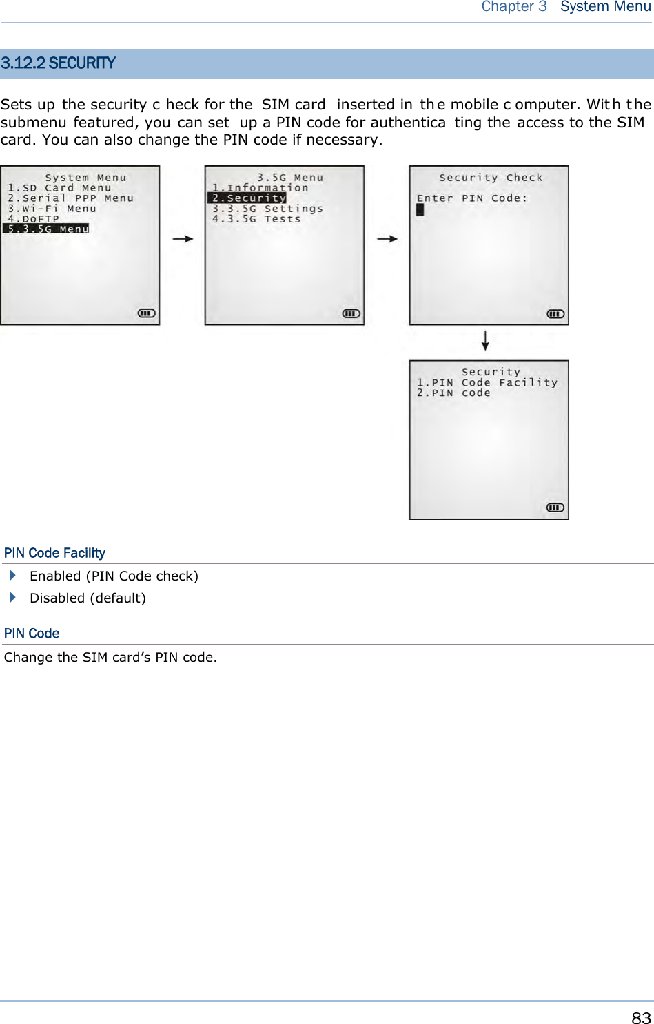
![45 System Menu is a powerful utility that offers an interface for engineers (programmers or system integrators) to view sys tem inform ation, cha nge t he co nfiguration par ameters, download programs and run diagnostics. As System Menu is intended for engineers’ te sts and maintenance ONLY, pa ssword protection is provided to pr event unauthorized users from accidentally changing system settings. Warning! System Menu is NOT for the use of any e nd users. T he system password helps ensure system safety and integrity. How to access the System Menu? 1) Turn off the mobile computer. 2) Press [7] + [9] + [Power] simultaneously. Chapter 3 SYSTEM MENU](https://usermanual.wiki/CipherLab/8770.User-Manual-1-of-2/User-Guide-1646570-Page-55.png)
![48 8700 Series Mobile Computer Reference Manual 3.2 SETTINGS This subm enu access es the mobile compu ter’s syste m settings and c hanges their defaults. An overview of the defaults: System Settings Default Values Clock Current time Backlight 20 seconds, Level 2 Auto Off 10 minutes Power On Options Resume Key Click Tone 2 System Password Open access Font System font Screen Calibration Select thi s command to align the co ordinates of the touch screen wi th those of the di splay underneath i t, so as to make the touch control precise. USB VCOM No. Fixed USB Charge Current 500 mA Default Set (=Reset to Default) Restores your mobile computer to default state. Reset Reader Restores the reader to default state. Contrast Level 4 3.2.1 CLOCK Sets the clock / calendar time for the mobile computer. Enter two digits for the year, e.g. 04 for 2004. 3.2.2 BACKLIGHT Sets the backlight duration for the keypad and LCD. Enter a value between 0 and 9999 (seconds). Press the navigation keys [Up] and [Down] to adjust the backlight level (4 levels).](https://usermanual.wiki/CipherLab/8770.User-Manual-1-of-2/User-Guide-1646570-Page-58.png)
![49 Chapter 3 System Menu 3.2.3 AUTO OFF Sets the mobile computer to automatically power off after idleness for a period of time. Enter a value between 0 and 999 (minute). Note: To disable this function, enter 0. 3.2.4 POWER ON (& WAKEUP EVENT) OPTIONS This i s a su bmenu t hat confi gures how the mobile computer starts up a nd what event wakes up the mobile computer: Power On Options Press the na vigation keys [Up] and [D own] to sel ect betwee n “Resume” and “Restart ”. Press [Enter] to select it. Resume: When the mobile computer is powered on, it resumes the last session of the program that was run before it is turned off. Restart: When the mobile computer is powered on, the system restarts over. WakeUp Events The events set can wake up the mobi le computer when it takes place. Pres s the navi gation keys [Up] and [Down] to move between the events, and press [Enter] to configure it to enforce the wake-up of the mobile computer or not. PwrKey: If set to yes, the mobile computer wakes up when the power key is pressed. RS232: If se t to yes, the mobi le computer wakes up when connected to a RS-232 por t (by RS232 cable). USB: If set to yes, the mobi le comput er wake s up when connected wi th to a USB port (by a USB cable). Charging: If set to yes, the mobile computer wakes up when getting charged via the cradle or direct charging. Charged: If set to yes, the mobile computer wakes up when charging completes. Alarm: If set to yes, the mobi le computer wakes up when the al arm time is up. Alarm can be set up through programming only. 3.2.5 KEY CLICK Sets the audible signal the mobile computer produces when a key is pressed on the keypad. Select a desired tone for the buzzer or mute it. 3.2.6 SYSTEM PASSWORD Sets a password to control over user’s access to the System Menu, Program Manager and Kernel Menu. The password allows up to eight alphanumeric characters.](https://usermanual.wiki/CipherLab/8770.User-Manual-1-of-2/User-Guide-1646570-Page-59.png)
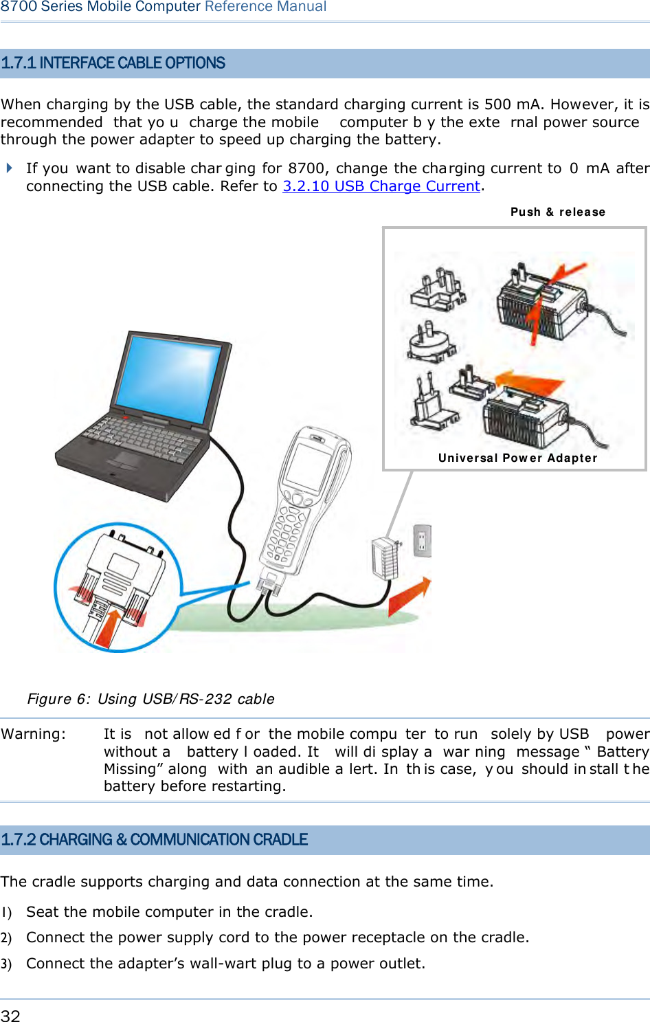
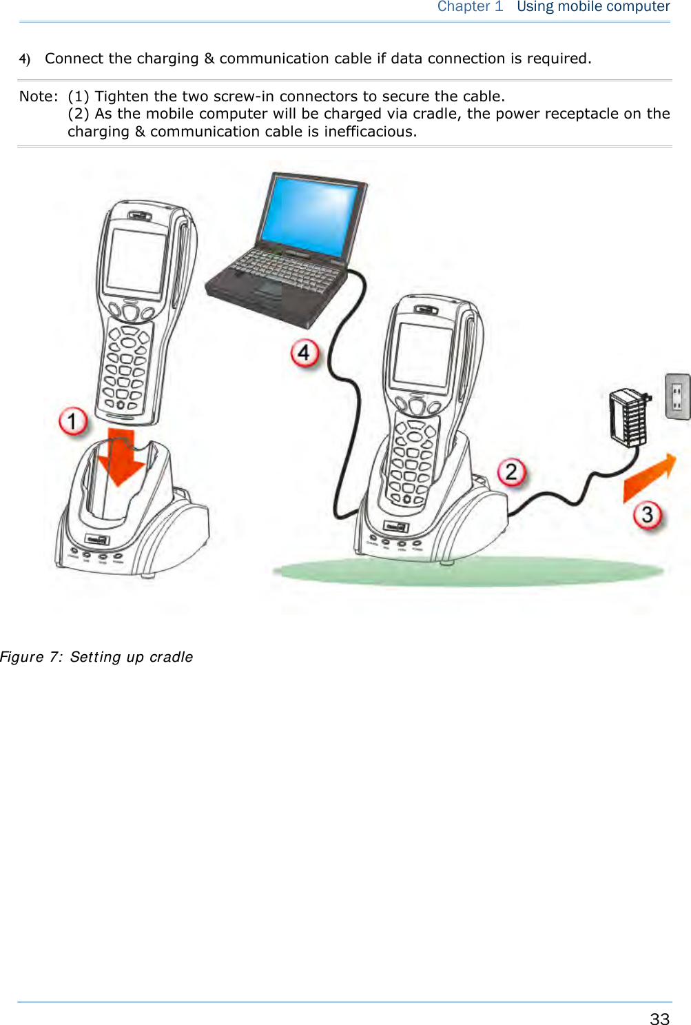
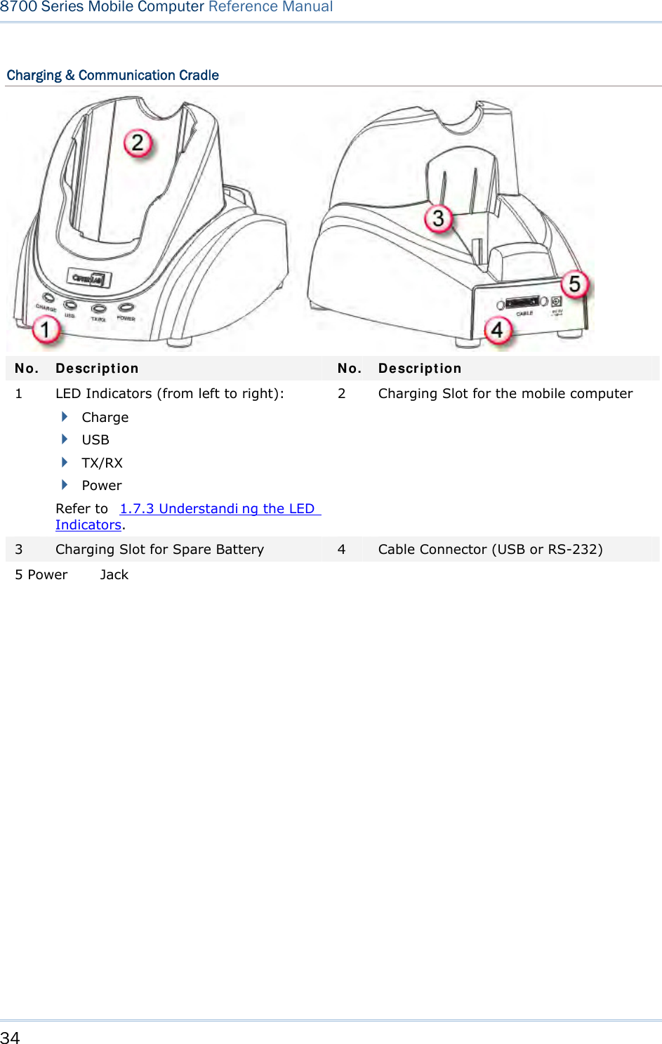
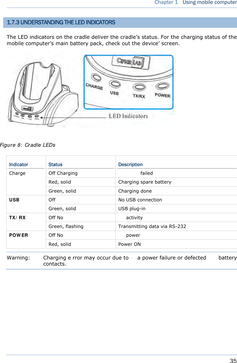
![50 8700 Series Mobile Computer Reference Manual Note: The password is case-sensitive. To disable a previous password, press both [Enter] when you are asked to "Input new password" and "Verify password". 3.2.7 FONT Shows the font information. It displays “System Font” if no custom font file is a ctive on the mobile computer. If a multi-language font file is downloaded, you are able to select a font from the list. 3.2.8 SCREEN CALIBRATION When a to uch screen has served for a period of t ime, it n eeds calibrat ion t o w ork accurately. C alibration improv es t he accu racy of t he touc h scr een by al igning the coordinates of the touch panel and the LCD underneath it. “Screen Cal ibration” is a command that l aunches the mobi le computer’s acti on directly. Upon your selecting this command, the screen di splay four cross marks, one at a time at the fo ur co rners of the screen. A ccurately and firmly tap on the centers of these cross marks using the stylus to follow through the calibration. Warning: DO NOT use any pointed or sharp object to tap on the screen. 3.2.9 USB VCOM NO. USB VC OM N o. is set t o “ Fixed” by def ault. “Fixed” m eans the m obile computer will always connect to a host computer (such a s your PC) by the same USB Vi rtual COM port regardless of how many mobile computers are connected to it earlier or later. When the USB VC OM No. is set to “Fixed”, yo u can only connect one mobile computer to your P C at one time. Such setting i s hel pful to configure a great amou nt of mobil e computers (for administrators’ or factory use). While in other cases, y ou may n eed to set USB VC OM No. to “Change with S/N”, wh ich means the number of th e virtual COM port in use will vary by th e serial number of each mobile computer connected to your PC. Press the n avigation k eys [U p] and [Down] to select be tween “Fixe d” a nd “Change with Serial Number”. 3.2.10 USB CHARGE CURRENT By default, the USB charging curr ent is se t to 500 mA. For direct charging via the USB cable without a power adapter, the standard charging current is 500 mA. Press the navigation keys [Up] and [Down] to select between “500 mA” and “0 mA”. To disable charging the mobile computer, select “0 mA”.](https://usermanual.wiki/CipherLab/8770.User-Manual-1-of-2/User-Guide-1646570-Page-60.png)
![51 Chapter 3 System Menu Note: (1) USB direct charging, 500 mA: USB icon (2) 5V charging from the adapter: Plug icon 3.2.11 DEFAULT SET Restores the system settings to default factory state, except for the reader settings. 3.2.12 RESET READER Restores the reader settings to factory default state. 3.2.13 CONTRAST Sets the contrast level for the LCD. Press the navigation keys [Up] and [Down] to adjust the contrast level (7 levels).](https://usermanual.wiki/CipherLab/8770.User-Manual-1-of-2/User-Guide-1646570-Page-61.png)
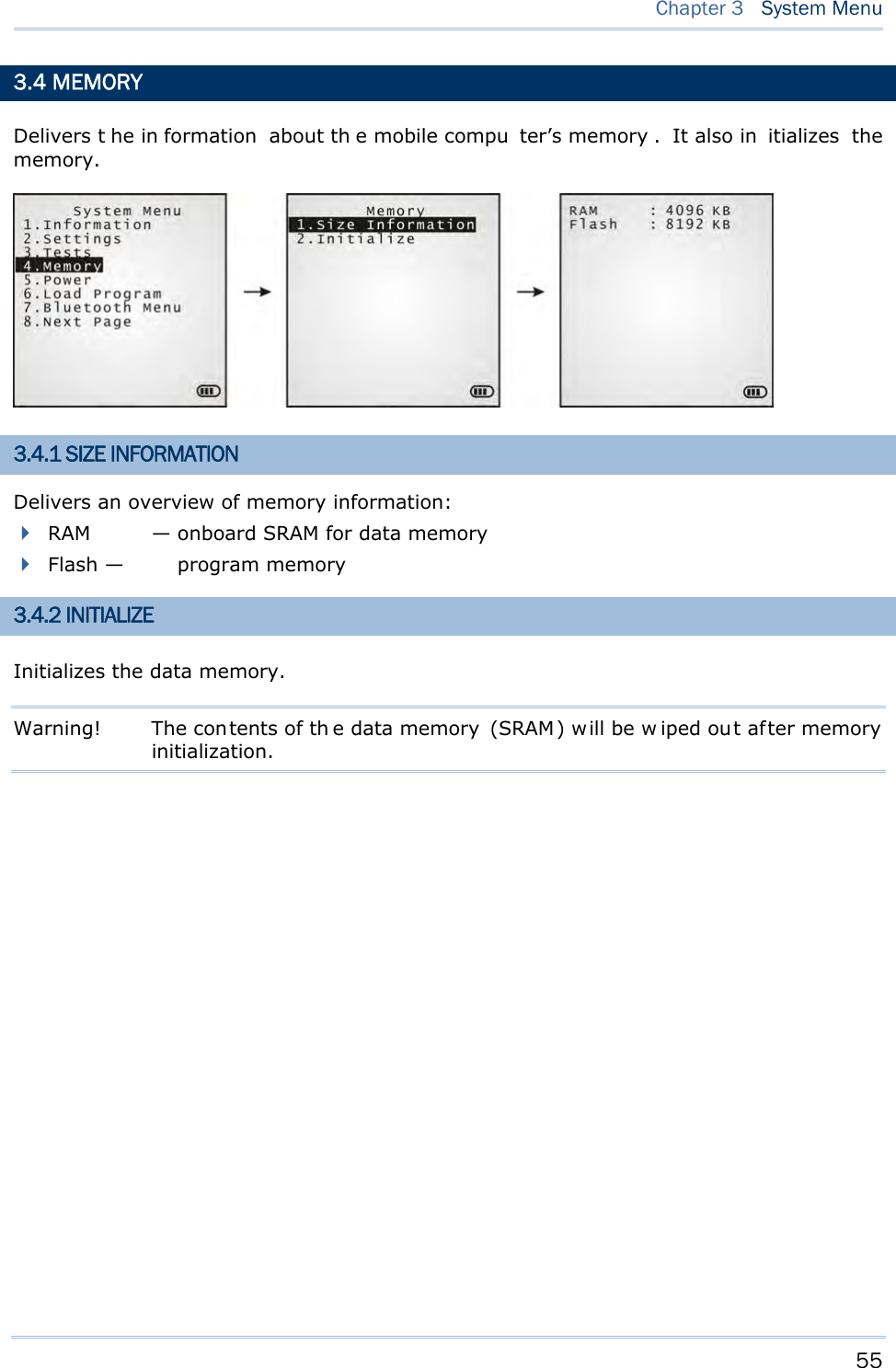
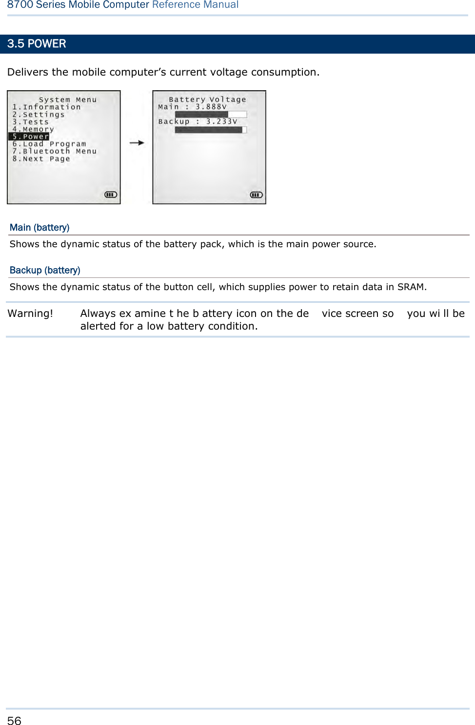
![52 8700 Series Mobile Computer Reference Manual 3.3 TESTS Provides a variety of functional tests on the mobile computer’s key parts. 3.3.1 READER Launches the test on the scanner’s reading performance. Symbologies supported depend on the scan engine you use. Refer to 1.6 Data Capture for the symbologies enabled by default. Symbologies disabled by default can only be enabled through programming. Press the [SCAN] key to start testing. To stop and quit the test, press any key. 3.3.2 BUZZER Launches the buzzer test with different frequency/duration combinations. To stop and quit the test, press any key. 3.3.3 LCD & LED Launches the test on the LCD display and LED indicator. To stop and quit the test, press any key. 3.3.4 KEYBOARD Launches t he test o n the keyp ad’s rubberized keys. Press any key to see if the corresponding character display on the screen. To stop and quit the test, press [ESC]. 3.3.5 MEMORY Launches the test on the mobi le computer’s data me mory (SRA M). The re sults wi ll display on the screen. To stop and quit the test, press [ESC]. Warning! The contents of the data memory (SRAM) will be wiped out after test.](https://usermanual.wiki/CipherLab/8770.User-Manual-1-of-2/User-Guide-1646570-Page-62.png)
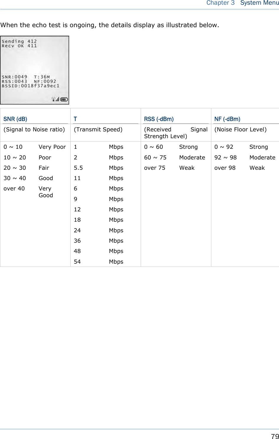
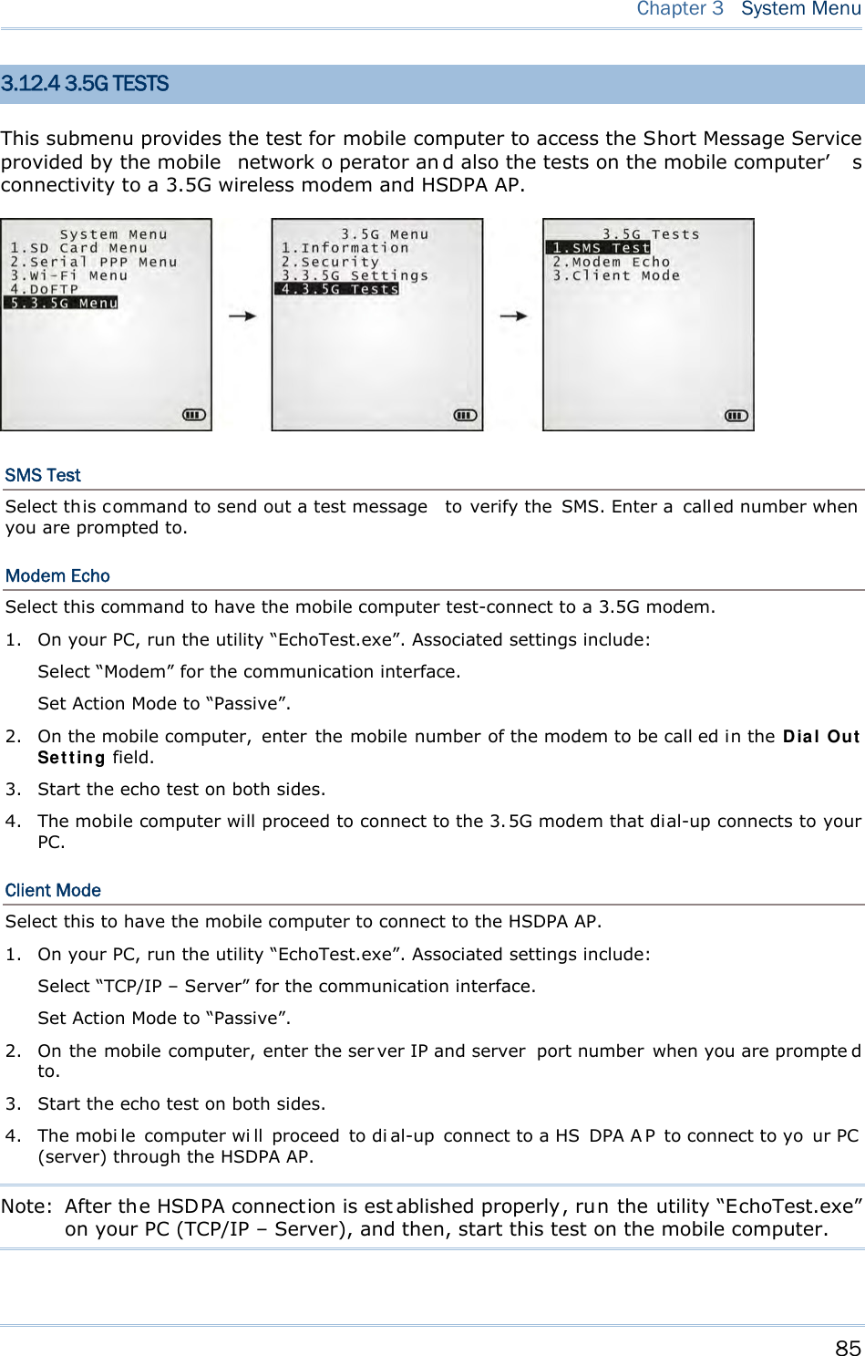
![53 Chapter 3 System Menu 3.3.6 TOUCH SCREEN Launches the test on the mobile computer’s signature capture with the help of the stylus. To stop and quit the test, press [ESC] or tap [OK] on the screen. 3.3.7 VIBRATOR Launches the test on the mobile computer’s vibrator. To stop and quit the test, press [ESC]. 3.3.8 ECHO TEST Launches t he test on the mobi le computer ’s data con nection est ablished th rough the physical USB cable or a RS-232 cable. Run the test utility on your PC while launching this test on the mobile computer. Select a desired baud rate if necessary. To stop and quit the test, press [ESC]. Interface Description Test Utility RS-232 This echo te st i s to veri fy the connectivity via the RS -232 cable between the mobile computer and a host computer. EchoTest.exe This echo test is to verify the connectivity via the USB cable between the mobile computer and a host computer. USB VCOM Echo — The mo bile c omputer wo rks a s a generic USB device. EchoTest.exe for Virtual COM USB HI D — T he mo bile c omputer wo rks a s a n in put device; sel ect keyboard t ype and Ca ps Lock statu s for running a test. Any text editor for HID USB USB VCOM_CDC Echo — The mobile computer wor ks as a generic USB device. EchoTest.exe for Virtual COM 3.3.9 RFID Launches the test o n the RFID re ader’s reading performance whe n a proximity card is present. Refer to 1.6.2 RFID Tags Supported for the supported RFID tags. To stop and quit the test, press [ESC]. Note: This test is available only when the RFID module is present.](https://usermanual.wiki/CipherLab/8770.User-Manual-1-of-2/User-Guide-1646570-Page-63.png)
![54 8700 Series Mobile Computer Reference Manual 3.3.10 GPS Launches t he test on the mobi le computer’s GPS receiver. It gives a general review of the mobile computer’s real t ime s peed an d posit ion in formation, and also t he sat ellite count and signal strength. To stop and quit the test, press [ESC]. Note: This test is available only when the GPS module is present.](https://usermanual.wiki/CipherLab/8770.User-Manual-1-of-2/User-Guide-1646570-Page-64.png)
![57 Chapter 3 System Menu 3.6 LOAD PROGRAM Launches t he mobi le computer’s L oad Program serv ice provided by the kernel. After a program is downloaded to the mobile comp uter, you won’t be abl e to return to System Menu by pressing [ESC] as the kernel will take over the job. In this case, restart the mobile computer to activate the new program. Refer to Appendix I Download Utility. Note: When RS-232 is selected for the transmission interface, the mobile computer stays in download mode for about 30 seconds only. The preparation (such as connecting the RS-232 cable) and the kernel update s hould be done before the download mode expires. The following files are downloadable by Load Program command: .SHX Program Downloadable C program files and/or font file: AG Runtime: U8700.shx (Batch AG) WU8700.shx (WLAN AG) CipherNet Runtime: 87xx-5250.shx (CipherNet-5250) 87xx-VT.shx (CipherNet-VT) BASIC RuntimeNote: B8700.shx Program File User program Font File Refer to the Font Files folder on CD-ROM. If you have downloaded a BASIC Runtime program, you will be able to select whether to download a C program (.SHX) or BASIC prog ram (.S YN) the next ti me you acc ess t he Load Program command. Note: (1) “Load Basic” menu is on ly av ailable af ter y ou h ave down loaded a BASIC Runtime program. (2) In add ition to the sys tem font, t here can be on ly on e more font f ile downloaded to the mobile computer.](https://usermanual.wiki/CipherLab/8770.User-Manual-1-of-2/User-Guide-1646570-Page-67.png)
![58 8700 Series Mobile Computer Reference Manual SETTINGS Interface Options Description RS232 Loading programs from RS232-interfaced devices such as your PC. The mobile computer nee ds t o connect to your PC with a RS 232 cable. Baud rate setti ngs are necessary o n both your PC and the mobile computer. USB VCOM Loading programs from USB-i nterfaced devi ces such as Your P C. Th e mobile computer needs to connect to your PC with a USB cable. Bluetooth Loading programs from Bluetooth-enabled devices. SD Card Loading p rograms d irectly fr om t he SD Ca rd in serted in t he mo bile computer. USB VCOM_CDC Loading prog rams from US B-interfaced devi ces such as Your P C. Th e mobile computer needs to connect to your PC with a USB cable. Baud Rate Available baud rate options: 115200/57600/38400/19200/9600 bps LOAD PROGRAM VIA BLUETOOTH 3) Go to System Menu | 7. Bluetooth Menu | 3. Security, a nd configure the following Bluetooth settings first. Authentication PIN code 4) Go to System Menu | 6. Load Program and select Bluetooth. 5) Have y our PC in itiate the pairin g w ith the mobile computer by clicking [Pair Device] and/or [Connect Bluetooth Serial Port]. 6) On y our PC, run the download utility ProgLoad.exe. In [C omm set ting] group box, make the following settings: - Select RS-232 for [Comm type], so as to access Bluetooth SPP. - Configure [C OM port] properties according to the Bluetooth COM port generated on your PC. Go to start | Control Panel | System | Hardware | COM & LPT to check it up.](https://usermanual.wiki/CipherLab/8770.User-Manual-1-of-2/User-Guide-1646570-Page-68.png)
![59 Chapter 3 System Menu LOAD PROGRAM VIA SD CARD 1) If you have copied the desired program file(s) to your SD card, go to System Menu | 6. Load Program and select SD Card. Yo u will s ee a list of all the files under the directory “\Program”, as shown above. 2) Press the navigation keys [Up] and [Down] to move between the listed files. 3) Press [Enter] to view information of the program file. 4) Press [Enter] to confirm downloading the program file to the mobile computer. Press [ESC] to abort the download task. Press the navigation keys to move between the files. Press [Enter] to select and view the information of the selected program file.](https://usermanual.wiki/CipherLab/8770.User-Manual-1-of-2/User-Guide-1646570-Page-69.png)
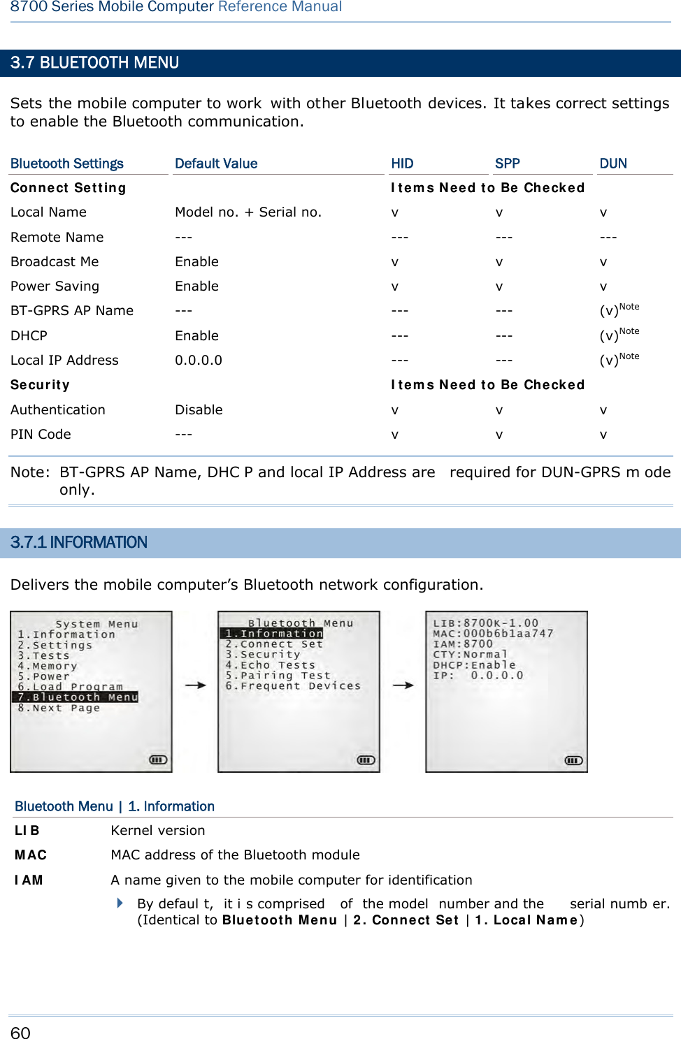
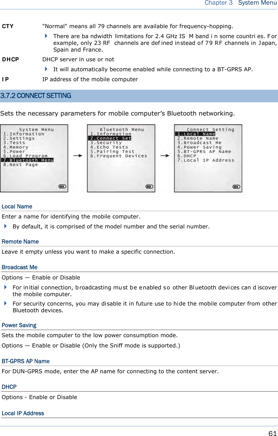
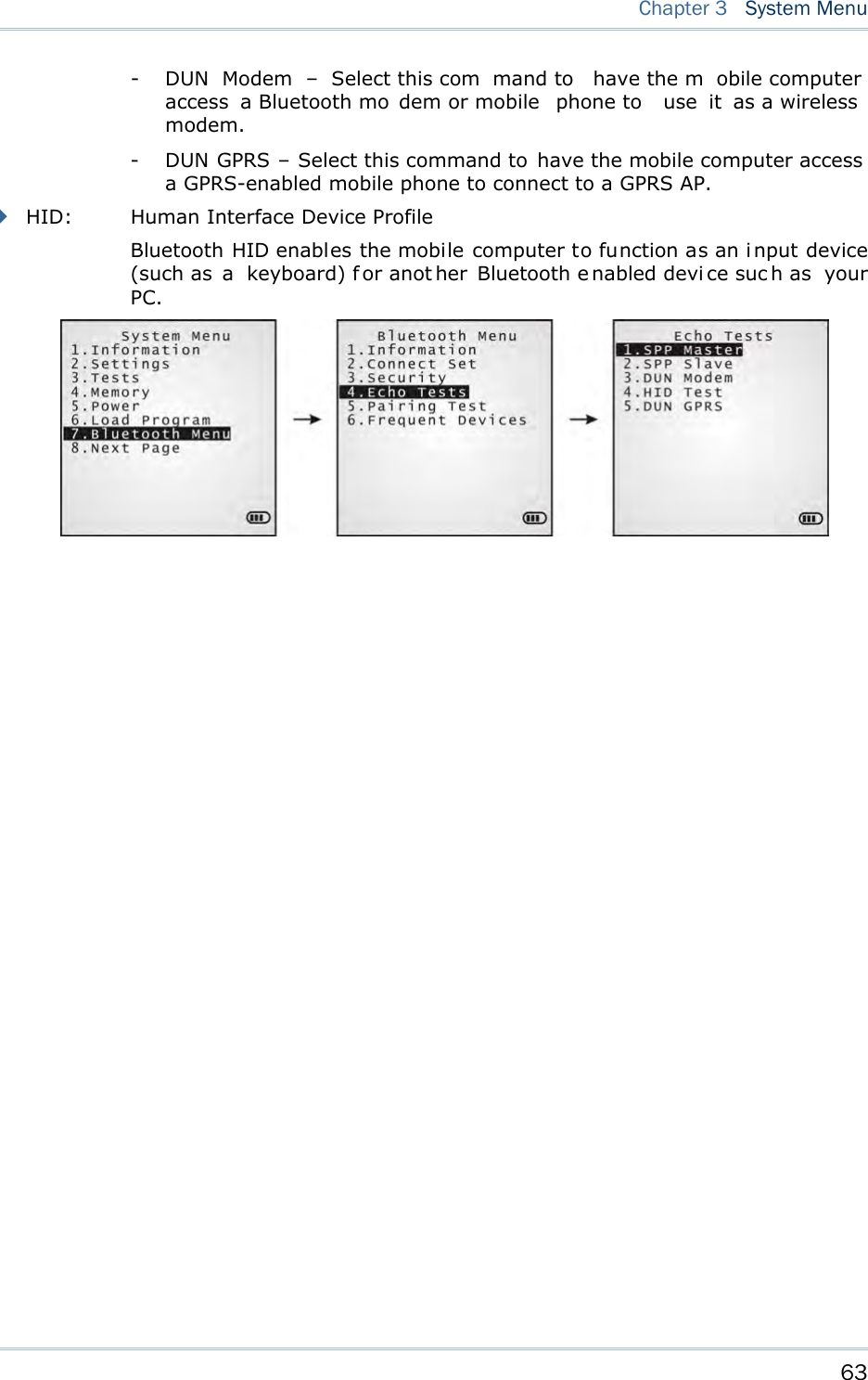
![62 8700 Series Mobile Computer Reference Manual Enter a new address for the mobile computer, if necessary. Note: BT-GPRS AP Name, DHCP and local IP Address are required for DUN-GPRS m ode only. 3.7.3 SECURITY Sets or modifies the security parameters for the mobile computer’s Bluetooth connection. Authentication Such “Authe ntication” concerns the pre-pairing vali dation between two Bl uetooth devi ces befor e they can communicate with each other. Options available are Enable and Disable. PIN Code Enter a “P in Code” to function fo r t he e ncryption ke y value. Pairing is o nly a chievable when t wo Bluetooth devices present the same Pin Code. Up to 16 characters, in ASCII format. Note: When aut hentication i s enabled without pro viding a pr e-set PIN code, the mobile computer supports dynamic input of PIN code during pairing. 3.7.4 ECHO TESTS Launches the echo tests that verify the mobile computer’s Bluetooth connectivity to make sure it sits within the wireless transmission range. Press [ESC] to stop and quit the test. Some key terms addressed in the submenu are defined as follows: SPP: Serial Port Profile Bluetooth SPP i s for Bl uetooth-enabled devi ces suc h as the mobile computer to wirelessly connect to an ad hoc network. DUN: Di al-Up Networking Profile Bluetooth DUN i s for Bl uetooth-enabled devi ces such as the mobile computer to access the Internet and other dial-up services.](https://usermanual.wiki/CipherLab/8770.User-Manual-1-of-2/User-Guide-1646570-Page-72.png)
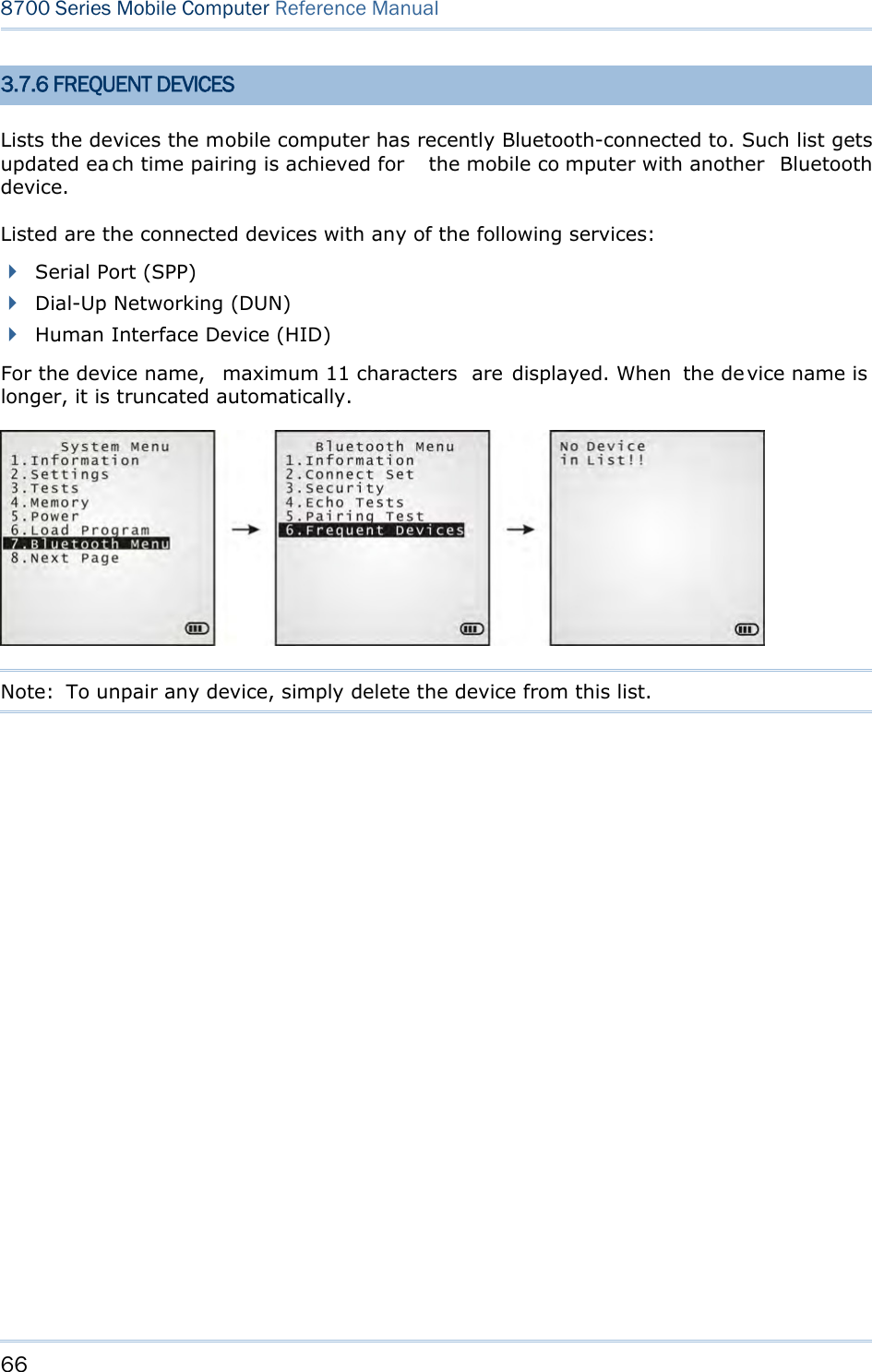
![65 Chapter 3 System Menu DUN GPRS Sets the mobile computer to connect to a mobile phone with 3.5G functionality. 1. Pairing with that mobile phone must be completed first. On the mobile computer, under when you are prompted to select the type of the target device, select “DialUp Network”. 2. Under the mobi le computer’s Echo Tests | 5. DUN GPRS command, enter the IP and port number of the server. 3. Run the utility “EchoTest.exe” on your PC. Associated settings include: - Select “TCP/IP – Server” for interface. - Set Action Mode to “Passive”. 4. Start the echo test on both sides. 5. The mobi le computer wi ll connect to the mobile phone that di als up a GPRS AP, and fi nally connect to your PC (server) through the GPRS AP. 3.7.5 PAIRING TEST Launches th e test if pairing is ach ieved bet ween two Blu etooth-enabled dev ices. P airing deals with the procedure whereby two Bluetooth-enabled devices accept each other’s connection request by creating an d exch anging a lin k k ey. Such lin k k ey remains efficacious for authentication when the two Bluetooth-enabled device s are exchanging information in the future 1) As soon as P airing Test is select ed, th e mobile compu ter starts to inquire the discoverable Bluetooth device(s) nearby, and the system will generate a list of them. 2) Select a target device to test connection. For th e device n ame, it can on ly display a max imum len gth of 11 ch aracters. When the device name is too long, it will be truncated automatically. 3) Select a Bluetooth service from the “Target Machine” menu. To stop and quit the test, press [ESC]. After pairing succeeds, the target device will be added to the Frequent Devices list for quick connection in the future. Note: For t he in itial u se of Blu etooth n etworking, the pairin g procedu re must be done before the Echo tests.](https://usermanual.wiki/CipherLab/8770.User-Manual-1-of-2/User-Guide-1646570-Page-75.png)
![67 Chapter 3 System Menu 3.8 SD CARD MENU Sets the mobile computer to a removabl e disk when equipped with a SD card. The files on the SD card can be accessed directly. Note: (1) As soon as a SD card is installed in the mobile computer, the card icon appears at the bottom of the screen. When the SD card is accessed, suc h icon starts to blink. (2) As long as the mobile computer is pre installed w ith Batch AG ru ntime, it w ill automatically create tw o working directories “\AG\IMPORT” and “\AG\EXPORT” as soon as a SD card is inserted. 3.8.1 RUN AS USB DISK When the mobile computer is eq uipped with a SD card and connected to your PC via a USB cable, it runs as a removable disk (U SB mass storage device) as long as it is configured properly through programming or via your selection of [Run as USB Disk]. Note: The SD card must be properly configured through programming or the menu here. 3.8.2 ACCESS SD CARD Edits the files on the SD card or formats the SD card. Edit Files Views and edits the files on the SD card. Format Formats the SD card and recreates file system. If the current file system on the SD card isn’t desired any more, you can format the SD card. If the capacity is 32 MB or less, the file system recreated will be FAT12. If the capacity is 32 MB~2 GB, the file system recreated will be FAT16. If the capacity is more than 2 GB, the file system recreated will be FAT32. Warning! The contents on the SD card will be wiped out after formatting.](https://usermanual.wiki/CipherLab/8770.User-Manual-1-of-2/User-Guide-1646570-Page-77.png)
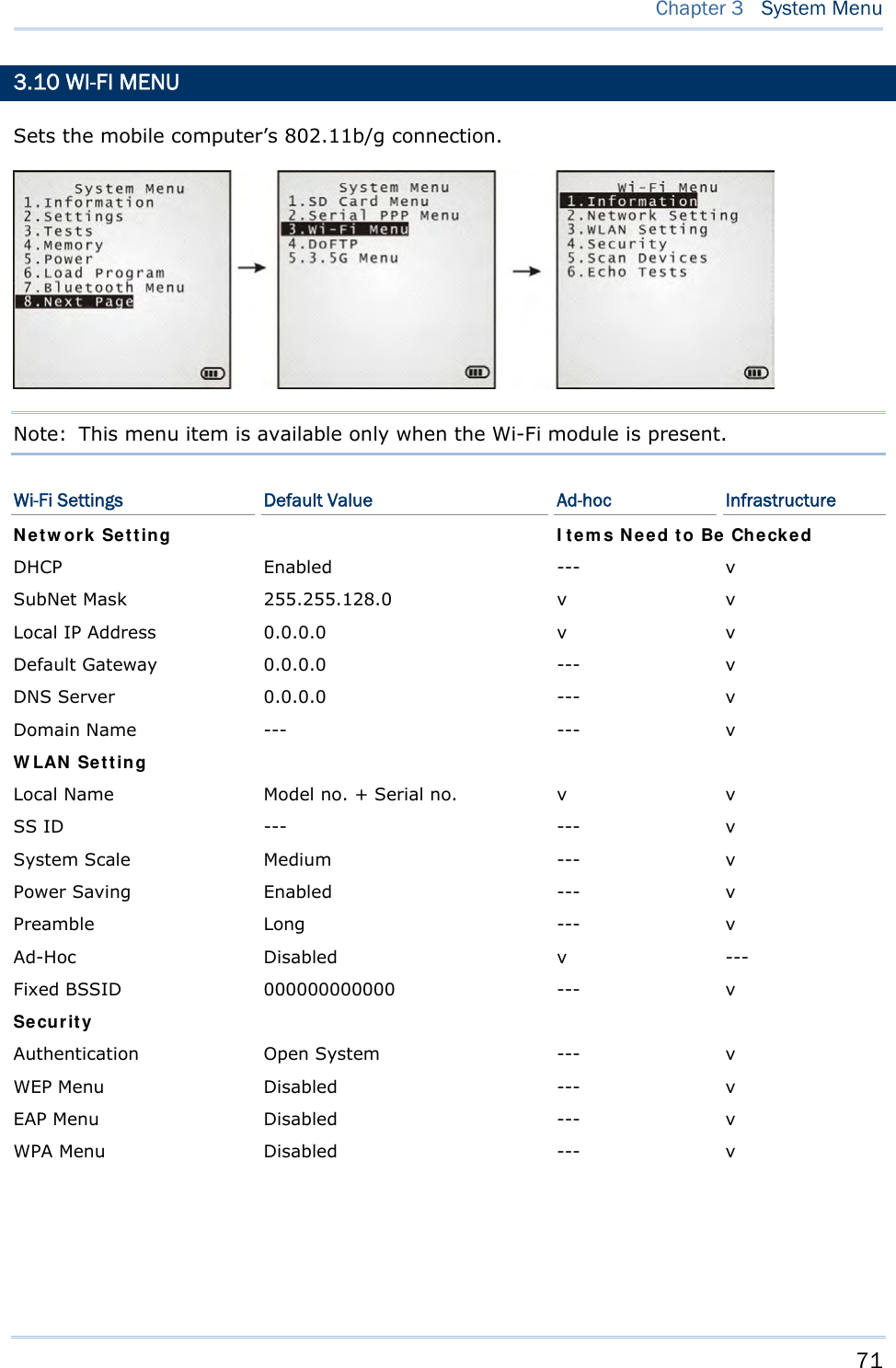
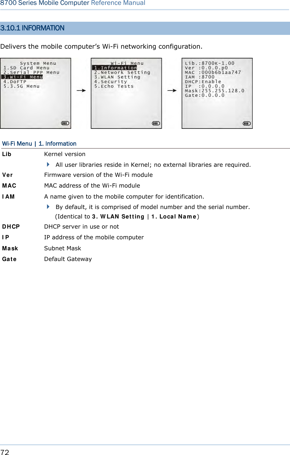
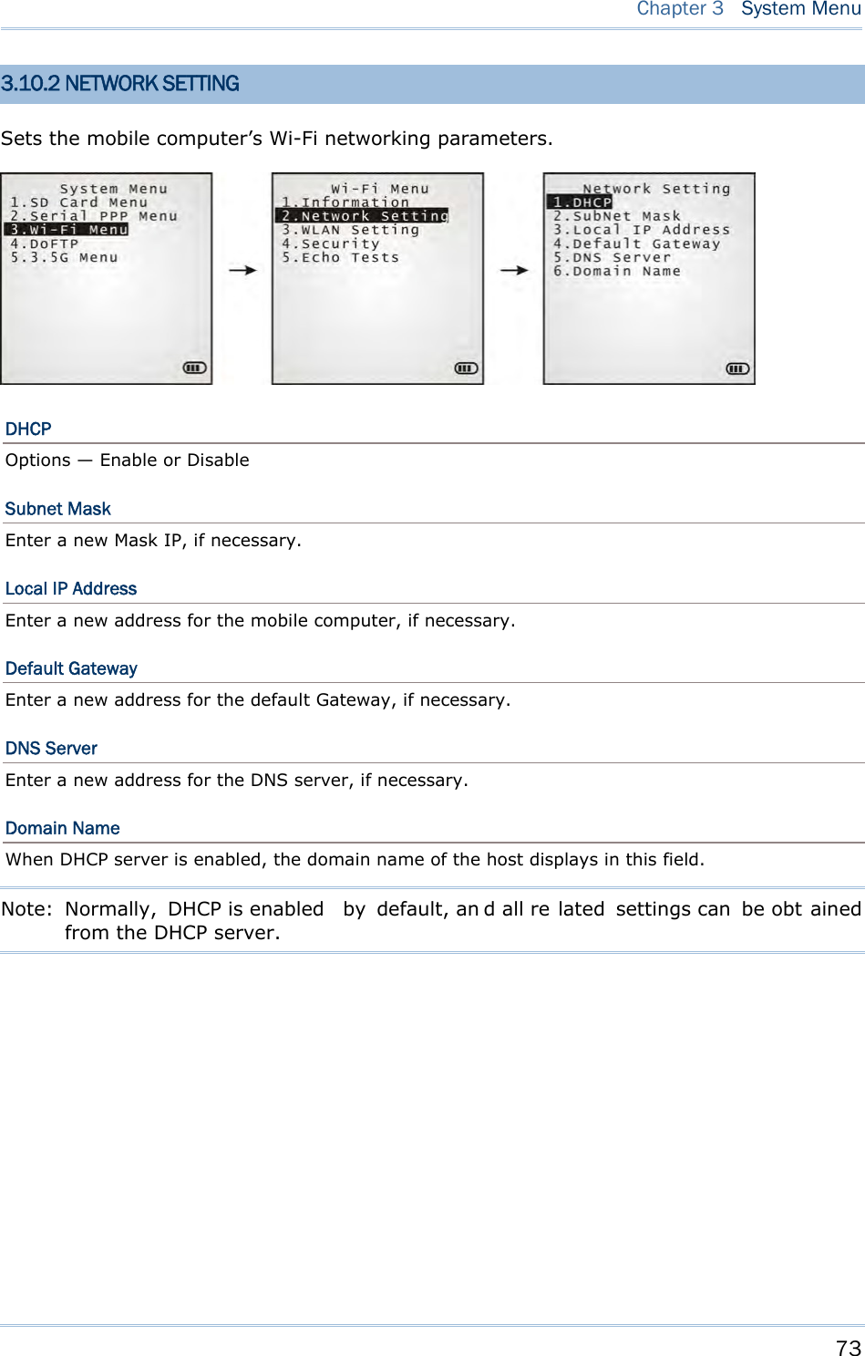
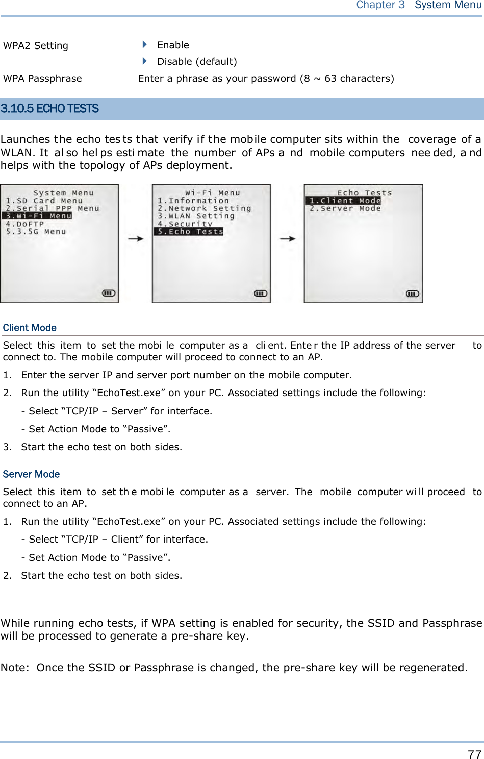
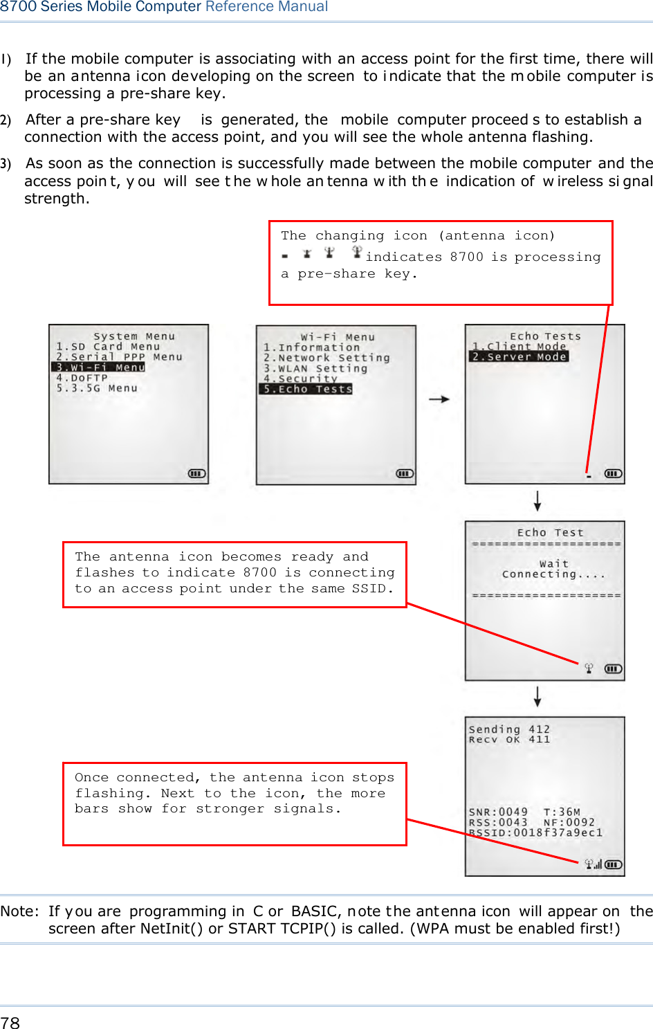
![74 8700 Series Mobile Computer Reference Manual 3.10.3 WLAN SETTING Sets the m obile computer’s Wi-Fi connection that works in ei ther mode – (1) Ad-hoc mode: peer-to-peer, or (2) Infrastructure mode: point to mu lti-point th rough access points. Set the following parameters: Local Name Enter a name for identifying the mobile computer. By default, the name is comprised of the model number and the serial number. SS ID “SS ID ” means “Service Set Identifier”. It coul d be the na me of the A P for remote device association. As l ong as a n SS I D is set, the mobile computer can ONLY communicate with the devices of the same SS ID. System Scale This refers to Access Point density. Options — [1] Low [2] Medium [3] High [4] Customized The setting must be consistent with that of the access point. Set to “Low”, “Medi um”, or “High” to have the mobi le computer scan for other access points when data transmission rate drops below “1”, “2” or “5” Mbps respectively. Set to “Customized” to have the mobi le computer scan for other access points when the data transmission rate drops below the following configurable values — 802.11b: 1, 2, 5.5, 11 Mbps 802.11g: 1, 2, 5.5, 11 Mbps & 6, 9, 12, 18, 24, 36, 48, 54 Mbps Power Saving This refers to the low power consumption mode. Options — Enable or Disable The setting must be consistent with that of the access point. Preamble Options — [1] Long [2] Short [3] Both The setting must be consistent with that of the access point.](https://usermanual.wiki/CipherLab/8770.User-Manual-1-of-2/User-Guide-1646570-Page-84.png)
![76 8700 Series Mobile Computer Reference Manual 3.10.4 SECURITY Sets or modifies the security parameters for the mobile computer’s Wi-Fi connections. WEP: Wired Equivalent Privacy EAP: Extensible Authentication Protocol WPA: Wi-Fi Protected Access Authentication [1] Open System “Open S ystem” is the defaul t. Where i t is set to “Open S ystem”, there is no authentication. [0] Share Key If it is set to “Share Key”, a WEP key needs to be set up. See WEP Menu in the following for details. WEP Menu WEP Setting Enabled (It must be enabled i f you will opt or have opte d for a “Share Key” for authentication.) Disabled (default) WEP Key Length 64 bits 128 bits (default) Default Key As the mobil e computer can store up to four WEP Keys, you can configure one WEP key to take force here in this submenu. If you don’t assign one, WEP KEY1 will be the default. WEP Key This submenu enables the configuration of WEP Keys 1 to 4 in either of the following format: ASCII (up to 13 characters) Hexadecimal (up to 26 characters) EAP Menu (for associating to Cisco access points) EAP Setting Enabled Disabled (default) EAP ID Enter a user name (up to 32 characters) EAP Password Enter a password (up to 32 characters) WPA Menu (WPA-PSK) WPA Setting Enabled Disable (default)](https://usermanual.wiki/CipherLab/8770.User-Manual-1-of-2/User-Guide-1646570-Page-86.png)


![87 This chapter will give you an account of the mobile computer’s Program Manager an d Kernel that manage multiple programs and firmware upgrade. IN THIS CHAPTER 4.1 Program Manager ...................................................... 87 4.2 Kernel ...................................................................... 92 4.1 PROGRAM MANAGER The mobile computer supports mu ltiple app lications an d lan guages. By t he men u of Program Manager, the mobile computer allows st oring up t o six programs plu s an activated one currently in use. If there is no application program stored in the mobile computer, the Program Manager will display on the screen when the mobile computer is powered on. Warning! Program Manager is provided for the program management in an administrative l evel. Non-administrative access to this menu s hould be properly warded off. To access Program Manager: 1) Turn off the mobile computer. 2) Press [8] + [Power] simultaneously. Chapter 4 PROGRAM MANAGER & KERNEL](https://usermanual.wiki/CipherLab/8770.User-Manual-1-of-2/User-Guide-1646570-Page-97.png)
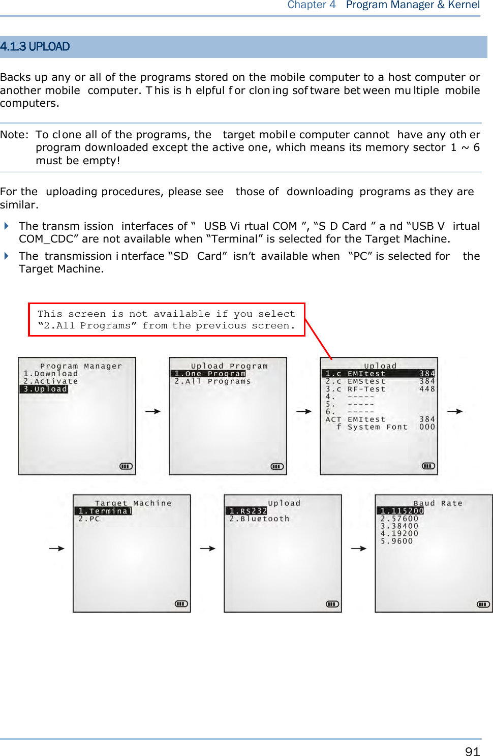
![88 8700 Series Mobile Computer Reference Manual 4.1.1 DOWNLOAD Select this item to loads programs for the mobile computer. When this item is selected, it first lists the programs currently stored on the mobile computer with size information. The program name allows up to 12 characters while program size is reflected in kilobytes. Multiple application programs are downloadable to the mobile computer through a variety of interfaces. When downloading finishes, you are prompted to input a new name for that program. If there is no need to rename it, simply pres s [Enter] to leave the name unchanged and quit the rename field. Each en try list ed in th e Download s ubmenu represe nts a prog ram that has been downloaded to the mobile computer. An entr y i s compri sed of t hree el ements: (1) The numbering, (2) the file name, and (3) the file size. They are detailed as follows: The numberings from 1 to 6: Among the numberings from 1 to 6, each re presents a memory sector availab le o n the mobile computer for a program to o ccupy. W hen a program is downloaded to occupy a memory sector, a suffix letter will disp lay af ter th e numbering of t hat memory sector to repr esent the file type of that progra m. There are two type s of program: - “b” for BASIC program (.SYN) - “c” for C program (.SHX) The file name: The file name of the downloaded program displays here. The f ile siz e: The f ile siz e of t he dow nloaded program display s h ere. It is giv en by kilobytes. At the bottom of this Download submenu, there are two lines:](https://usermanual.wiki/CipherLab/8770.User-Manual-1-of-2/User-Guide-1646570-Page-98.png)
![89 Chapter 4 Program Manager & Kernel The line starting with “ACT” indicates the program that is activated and in use on the mobile com puter at the moment. This is the program that is executed when the mobile computer’s system starts up. The line starting with the letter “f” is a reserv ed line to display the font file (.SHX) in use by the mobile computer at the moment. Note: For a custom font file (.SHX) or a BASIC program (.SYN), it can o nly b e downloaded via System Menu | 6. Load Program. MEMORY SECTOR (1 ~ 6) A vacant cell in Download submenu represents a memor y sector that is availa ble for a program to occupy. Download a program file to an available memory sector: 1. Press the navigation keys [Up] and [Down] to move between the items. Press [Enter] to select one. 2. Select a desired interface for downloading. 3. Connect the interface cable if required. 4. On your PC, run the utility ProgLoad.exe. Make necessary configuration on its user’s interface, select the pr ogram to do wnload, and press OK but ton to proce ed. The mobile computer will start to download the selected program. 5. To abort the action, press [ESC]. Then press [ESC] again to return to the submenu. Download a program file to an occupied memory sector: If no more memory sect or is ava ilable, you have to remove a downloaded program t o make storage space for the new one. 1. Press the navigation keys [Up] and [D own] to move between the downloaded programs. Press [Enter] to select one to remove. 2. The program information displays on the screen. Press the modifier key [α] to switch to upper-case alphabetic input mode: Press the capital letter [C] and follow the steps below to download a program file. Press the capital letter [D] if you simply want to delete the program. 3. Select a desired interface for downloading. 4. Connect the interface cable if required. 5. On your PC, run the utility ProgLoad.exe. Make necessary configuration on its user’s interface, select the pr ogram to do wnload, and press OK button to proce ed. The mob ile computer will start to download the assigned program. 6. To abort the action, press [ESC]. Then press [ESC] again to return to the submenu. From the menu, you' ll s ee the progr am has b een del eted bu t no new program i s presen t (because you have canceled the download action). ACTIVE STORAGE MEMORY SECTOR (“ACT”) Only the applicat ion program that n eeds to be ac tivated i mmediately should be downloaded to this memory sector.](https://usermanual.wiki/CipherLab/8770.User-Manual-1-of-2/User-Guide-1646570-Page-99.png)
![90 8700 Series Mobile Computer Reference Manual Download to Memory Sector “ACT”: 1. Press the navigation key [Down] to move down to the acti ve memory sector, “ACT”, whi ch may be unoccupied already. Press [Enter] to select it. 2. Select a desired interface for downloading. 3. Connect the interface cable if required. 4. On your PC, run the utility ProgLoad.exe. Make necessary configuration on its user’s interface, select the pr ogram to do wnload, and press OK button to proce ed. The mob ile computer will start to download the assigned program. If the acti ve memory sector has al ready been occu pied by an a pplication program, the newl y downloaded program will overwrite the old one and come to activation immediately. 4.1.2 ACTIVATE Select thi s i tem to acti vate a program on the mobile computer. When this item is selected, it f irst list s all the spare programs stored on the mobile computer t hat i sn’t active at the moment. Select any one from the list (from 1 to 6) or select the SD card. T he selected program will be copied to the active memory sector and replace the current one. Note: A font file cannot be activated. As soon as a program is activated, the mob ile computer shuts down. When you power it on again, a screen appears sho wing the message <New Program Start>, take t he following action to keep or clear out the files in the SRAM: TO CLEAR FILE SYSTEM Press [ES C] to clean out the files in the S RAM. In this case, no data (transactions, settings, etc.) is kept on the mobile computer when the new program comes into play. TO KEEP FILE SYSTEM To keep the files, simply press any key other than [ESC].](https://usermanual.wiki/CipherLab/8770.User-Manual-1-of-2/User-Guide-1646570-Page-100.png)
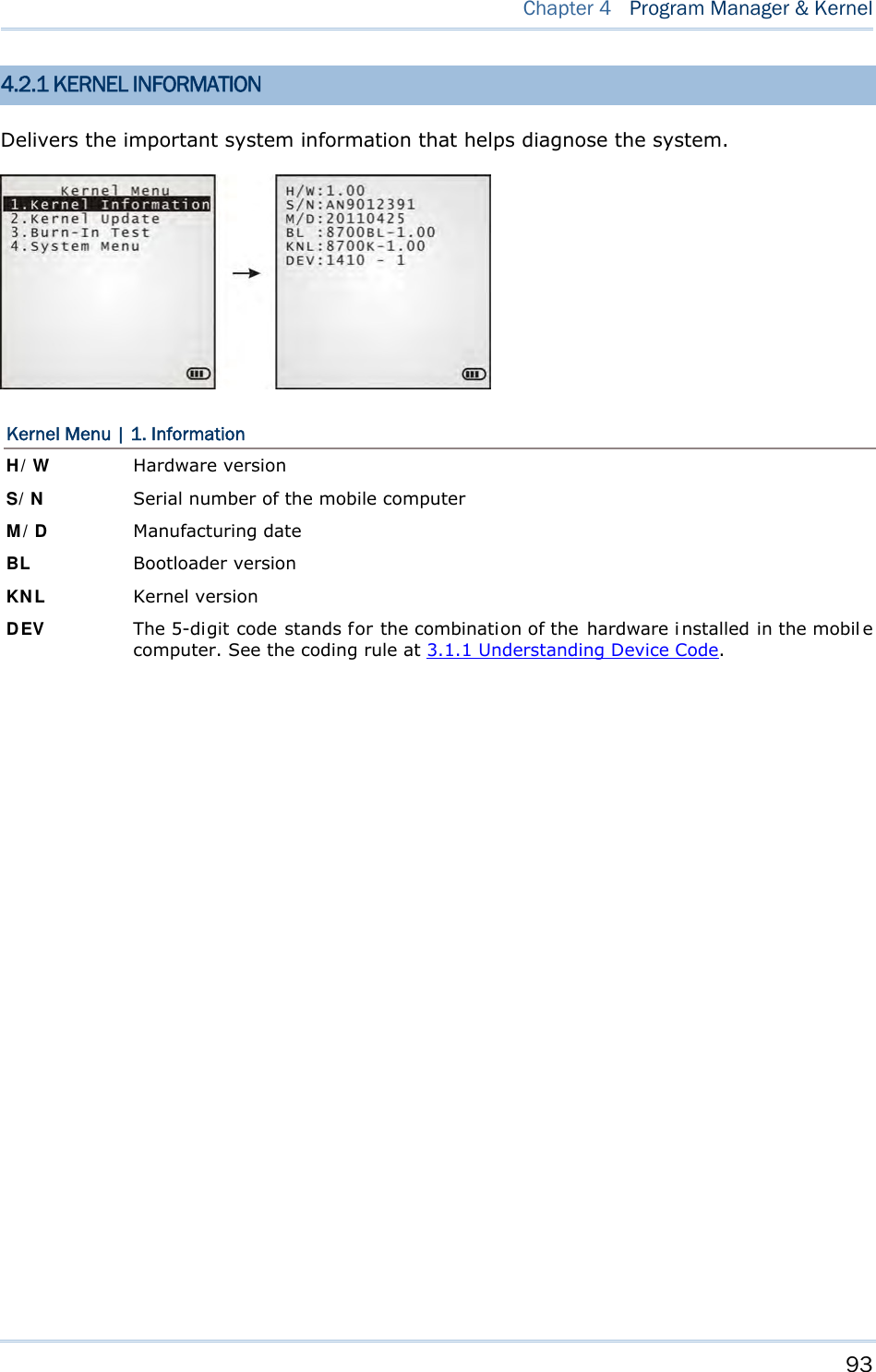
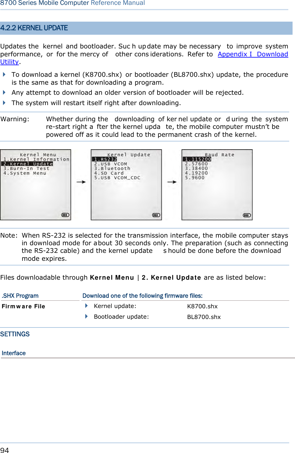
![92 8700 Series Mobile Computer Reference Manual 4.2 KERNEL The kernel resides in the innerm ost core of the system. It has the highest security and is always protected by the system. When the application program is corrupted and System Menu fails at the same time, Kernel Menu provides an access to fix the system. Warning! Kernel Menu is intended for the sys tem m anagement of admi nistrator’s level. Non-administrative access to this menu should be warded off. To access Kernel Menu: 1) You need to power off the mobile computer first. When the last session is in System Menu or Program Manager, si mply turn off the mob ile computer; otherwi se just reload the battery pack. 2) Press [1] + [7] + [Power] simultaneously.](https://usermanual.wiki/CipherLab/8770.User-Manual-1-of-2/User-Guide-1646570-Page-102.png)
![95 Chapter 4 Program Manager & Kernel Options Description RS232 By selecting RS232 interface, you nee d to configure baud rate settings both on your PC and the mobile computer. USB VCOM By sel ecting USB Vi rtual COM for the transmi ssion i nterface, your PC and the mobile computer shoul d be connected wi th a USB cabl e before the update can be done. Bluetooth By sel ecting B luetooth f or the transmi ssion interface, you se lect to approach a Bluetooth enabled device for kernel update. SD Card By sel ecting SD card for interface, yo u sel ect to access the SD card inserted in the mobile computer to carry out kernel update. USB VCOM_CDC By selecting USB Virtual COM_CDC for the transmission interface, your PC and the mobi le computer should be connecte d wi th a USB cabl e before the kernel update can be done. This o ption is a vailable o nly when USB Virtual COM_CDC is in use. Baud Rate Available baud rate options: 115200/57600/38400/19200/9600 bps KERNEL UPDATE VIA BLUETOOTH 1) Go to Kernel Menu | 4. System Menu | 7. Bluetooth Menu | 3. Security, an d configure the following Bluetooth settings first. Authentication PIN code 2) Go to Kernel Menu | 2. Kernel Update and select Bluetooth. 3) Start t he p airing procedure from your PC, for exampl e, cl ick [Pai r Devi ce] a nd/or [Connect Bluetooth Serial Port]. 4) On y our PC, run the download utility ProgLoad.exe. In [C omm set ting] group box, make the following settings: - Select RS-232 for [Comm type], so as to access Bluetooth SPP. - Configure [COM port] properties according to the Bluetooth COM port created on your P C. Go to start | Control Panel | System | Hardware | COM & LPT to check it up.](https://usermanual.wiki/CipherLab/8770.User-Manual-1-of-2/User-Guide-1646570-Page-105.png)
![96 8700 Series Mobile Computer Reference Manual KERNEL UPDATE VIA SD CARD 1) If the desired program file(s) has been copied to your SD card, go to Kernel Menu | 2. Kernel Update a nd select SD Card. A list of all t he files ex isting under t he directory “\Program” on the SD card will display, as shown above: 2) Press the navigation keys [Up] and [Down] to move between the files. 3) Press [Enter] to view the information of the program file. 4) Press [Enter] again to confirm dow nloading th e select ed program f ile t o th e mobil e computer. 5) Press [ESC] to abort the download task. In SD card directory, press the navigation keys to move between the files. Press [Enter] to select a file and view its information.](https://usermanual.wiki/CipherLab/8770.User-Manual-1-of-2/User-Guide-1646570-Page-106.png)

![109 24-KEY KEYPAD SYSTEM DEFAULTS Key [α] key pressed once [α] key pressed twice Key [fn] key pressed once [fn] key pressed twice 1 Space Space 1 F1 1 2 ABC abc 2 F2 2 3 DEF def 3 F3 3 4 GHI ghi 4 F4 4 5 JKL jkl 5 F5 5 6 MNO mno 6 F6 6 7 PQRS pqrs 7 F7 7 8 TUV tuv 8 F8 8 9 WXYZ wxyz 9 F9 9 - +$_ +$_ - - - 0 /* /* 0 F10 0 . %#;, %#;, . . . Appendix III KEY REFERENCE TABLES](https://usermanual.wiki/CipherLab/8770.User-Manual-1-of-2/User-Guide-1646570-Page-119.png)
![110 8700 Series Mobile Computer Reference Manual 44-KEY KEYPAD SYSTEM DEFAULTS Key [α] key pressed once [α] key pressed twice Key [fn] key pressed once 1 A a 1 ^ 2 B b 2 & 3 C c 3 4 D d 4 [ 5 E e 5 ] 6 F f 6 7 G g 7 < 8 H h 8 > 9 I i 9 ? - J j - $ 0 K k 0 % . L l . #](https://usermanual.wiki/CipherLab/8770.User-Manual-1-of-2/User-Guide-1646570-Page-120.png)
![111 Appendix III Key Reference Tables Key [α] key pressed once [α] key pressed twice Key [fn] key pressed once F1 M m F1 + F2 N n F2 - F3 O o F3 * F4 P p F4 / F5 Q q F5 = F6 R r F6 F16 F7 S s F7 F17 F8 T t F8 F18 F9 U u F9 F19 F10 V v F10 F20 F11 W w F11 F21 F12 X x F12 F22 F13 Y y F13 F23 F14 Z z F14 F24 F15 null null F15 _](https://usermanual.wiki/CipherLab/8770.User-Manual-1-of-2/User-Guide-1646570-Page-121.png)