CipherLab 9600 TERMINAL User Manual 9600 Reference Manual Herbie
CipherLab Co., Ltd. TERMINAL 9600 Reference Manual Herbie
UserManual.wiki
>
CipherLab
>
9600 User Manual
user manual
Navigation menu
Upload a User Manual
Namespaces
Wiki Guide
HTML
PDF
Info
Views
User Manual
Discussion / Help
Navigation
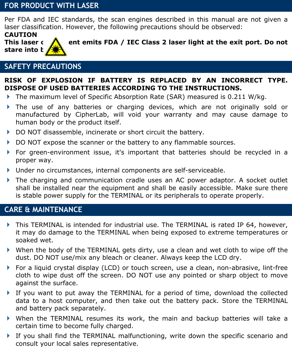

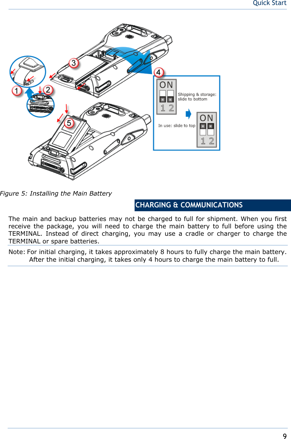

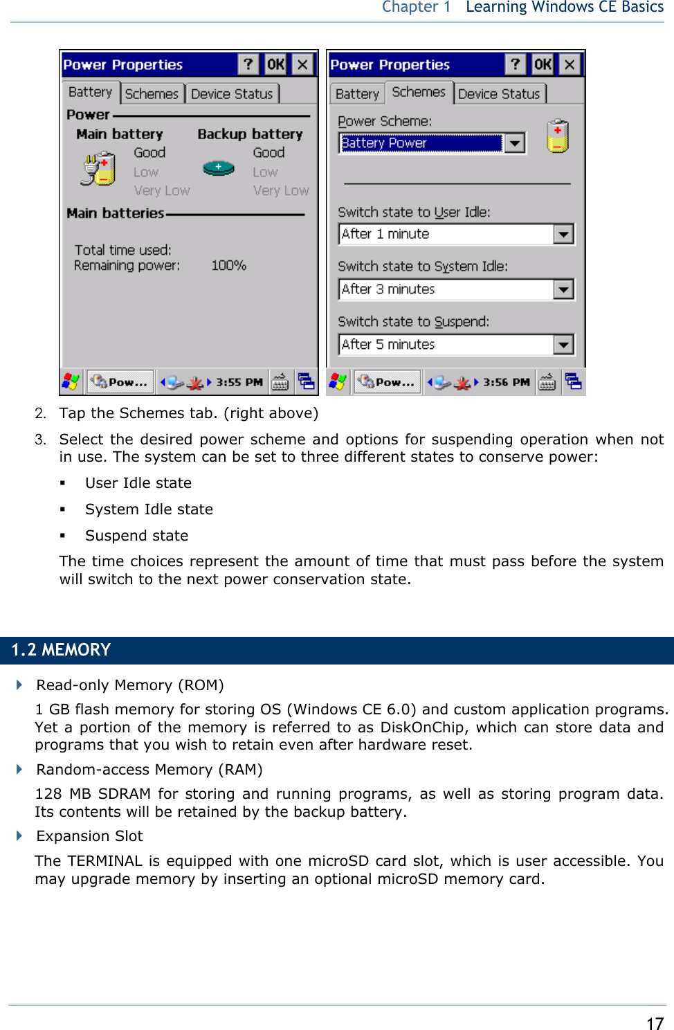
![16 9600 Mobile ComputerReference Manual 1.1.1 UNDERSTANDING THE BATTERY ICONS The battery pack is the only power source for the TERMINAL to work. It also charges the backup battery on the main board so that the data stored in SRAM can be retained properly. Therefore, when the main battery charge goes low, you need to replace the battery pack with a charged one or charge it as soon as possible. Most of all, you should backup important data on a regular basis. By looking at the battery icon, you can tell battery charge remaining in the main battery – the higher the green level, the more power in the main battery. Double-tap a battery icon so that you can quickly access the [Power Properties] dialog box. Battery Icons Description External power source is connected and main battery is charging External power source is connected but main battery needs no charging Main battery level 100% ~ 80% Main battery level 79% ~ 60% Main battery level 59% ~ 40% Main battery level 39% ~ 31% Main battery charge becomes low (30% ~ 15%) and needs charging Main battery charge becomes very low (14% ~) and needs charging immediately Backup battery charge becomes low and needs charging. Backup battery charge becomes very low and needs charging immediately. Warning: Data loss may occur with SRAM during low battery condition. Always save data before running out of power or keep a fresh battery for replacement. 1.1.2 POWER MANAGEMENT For any portable device, power management is a critical issue especially when you are on the road. Below are some tips to help you save battery power. Warning: Using backlight, wireless connectivity, and peripherals while on battery power will substantially reduce battery power. Bring a second battery pack on the road. Stop wireless connectivity, Bluetooth, 802.11b/g or GPRS that is not in use. Go to Start | Settings | Control Panel and double-tap the Display icon. Refer to 1.4.1 Adjusting the Backlight. Go to Start | Settings | Control Panel and double-tap the Power icon. (below) 1. In the Battery tab (left below), you can always monitor the charging status.](https://usermanual.wiki/CipherLab/9600/User-Guide-1186622-Page-24.png)
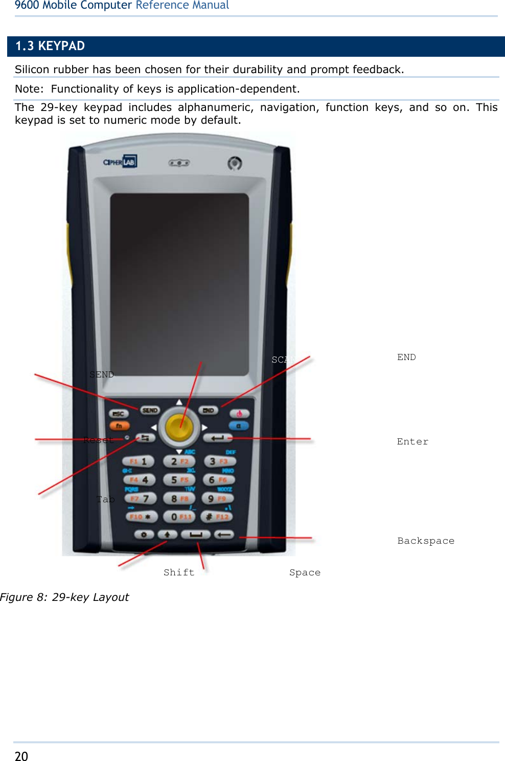
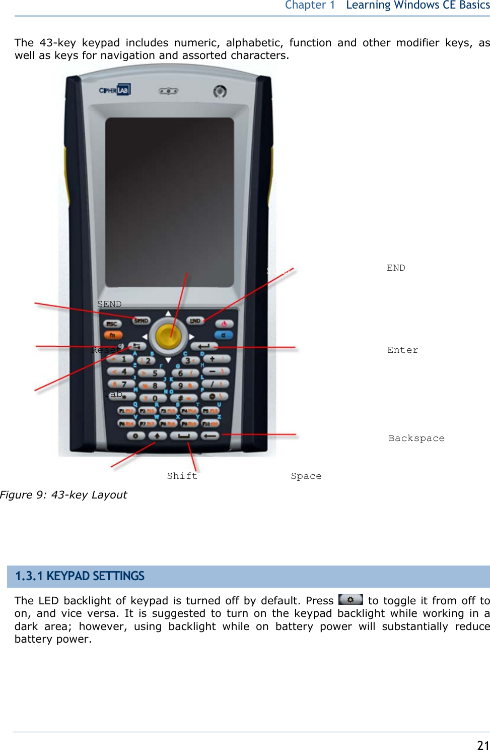
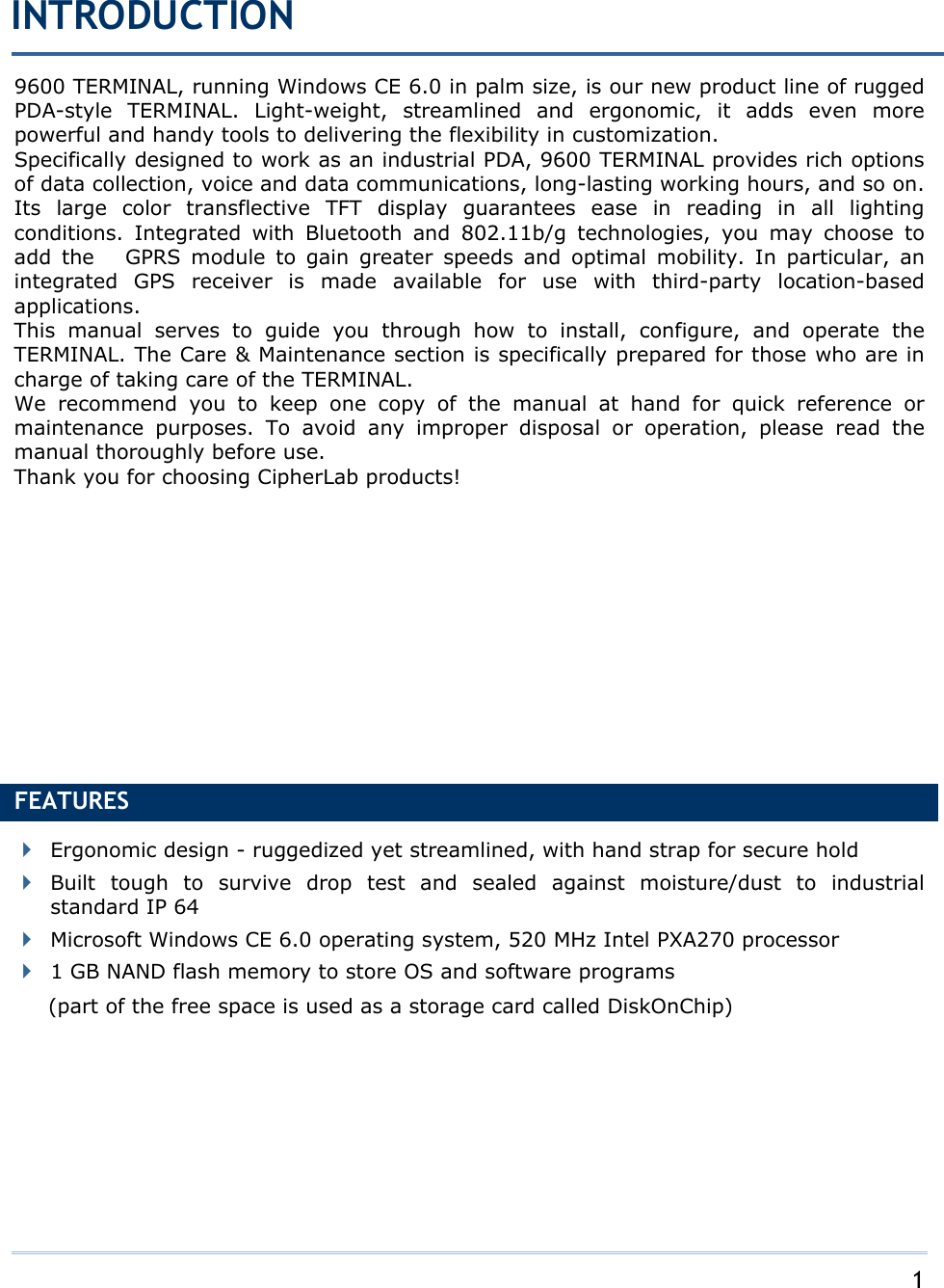
![22 9600 Mobile ComputerReference Manual The Character Repeat functionality is enabled by default. Go to Start | Settings | Control Panel and double-tap the Keyboard icon. You may cancel the check box to disable it. When enabled, tap, hold, and drag the slider for a desired Repeat Delay and Repeat Rate. 1.3.2 ALPHA KEY This alphanumeric keypad is set to numeric mode by default. The Alpha key serves as a toggle among numeric, alpha (lower-case alphabetic), and ALPHA (upper-case alphabetic) input modes. Note: It is not necessary to hold down the [Alpha] key. The alpha icon will appear on the status bar in a sequence as shown below. Status Icon Alpha Key Input Mode N/A Numbers Press one time Lower-case alphabetic Press two times Upper-case alphabetic Note: If you are using the software keypad via SIP, tap CAP (Caps Lock) to toggle between upper case and lower case alphabetic modes. 1.3.3 SPECIAL KEY Status Icon Shift Key Input Mode Press one time The Shift key modifies the next key pressed. For 29-key keypad operation, it will result in different symbols. Refer to 錯誤! 找不到參照來源。. 1.3.4 FUNCTION KEY The [FN] (function) key serves as a modifier key, and the functionality of each key combination is application-dependent. 1) To enable this modifier key, press on the keypad. Its icon will appear on the status bar. 2) Now press another key to get the value of key combination (say, press [1] to get the value of F1). The icon will go off now. 3) To get the value of another key combination modified by the [FN] key, repeat the above steps. 4) To abort the key modification, press again, and the icon will go off.](https://usermanual.wiki/CipherLab/9600/User-Guide-1186622-Page-30.png)
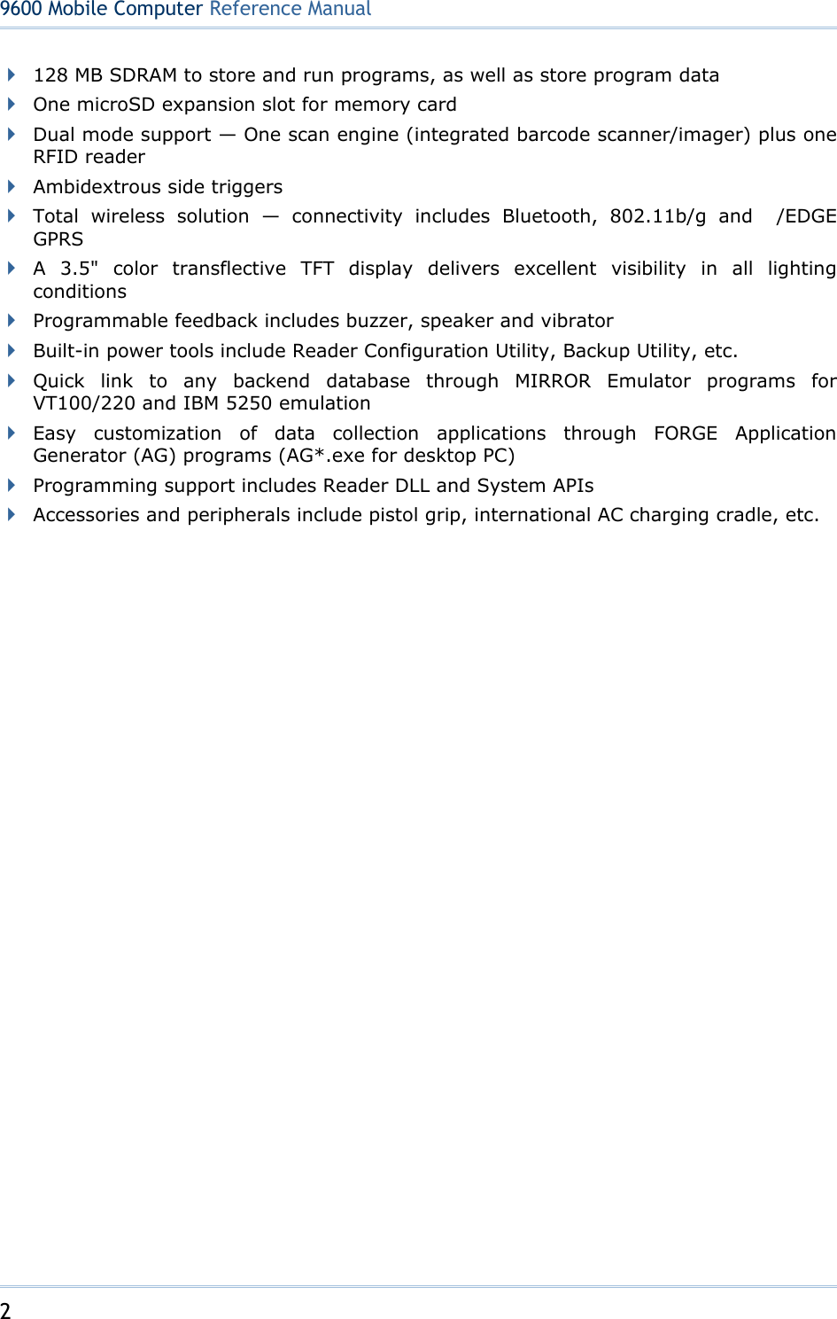
![23 Chapter 1 Learning Windows CE Basics Note: It is not necessary to hold down the [FN] key. Below is a list of the factory setting for a variety of key combinations. Key Combination Action , Move text up one screenful (Page Up) , Move text down one screenful (Page Down) , Move to the beginning of screen or document (Home) , Move to the end of screen or document (End) Toggle ON/OFF the backlight of keypad only Note: Press the [FN] key first, and then press the second key for a specific function. 1.3.5 PROGRAMMABLE KEYS The following keys are user-definable. They can be re-defined as another key or to serve as a shortcut key for launching a specific program. Refer to 錯誤! 找不到參照來源。. SCAN SEND END Two side triggers on each side of the touch screen 1.4 TOUCH SCREEN The TERMINAL comes with a 3.5" TFT graphic LCD, 320 by 240 pixels resolution (QVGA) or 640 by 480 pixels resolution (VGA). The LED backlight of screen, which helps ease reading under dim environments, can be controlled manually and automatically. Warning: Using backlight while on battery power will substantially reduce battery power. It is suggested to dim the backlight while working in a well-lit area or automatically turn off the TERMINAL when not in use. 1.4.1 ADJUSTING THE BACKLIGHT 1) Go to Start | Settings | Control Panel and double-tap the Display icon. 2) Tap the Backlight tab. (left below)](https://usermanual.wiki/CipherLab/9600/User-Guide-1186622-Page-31.png)
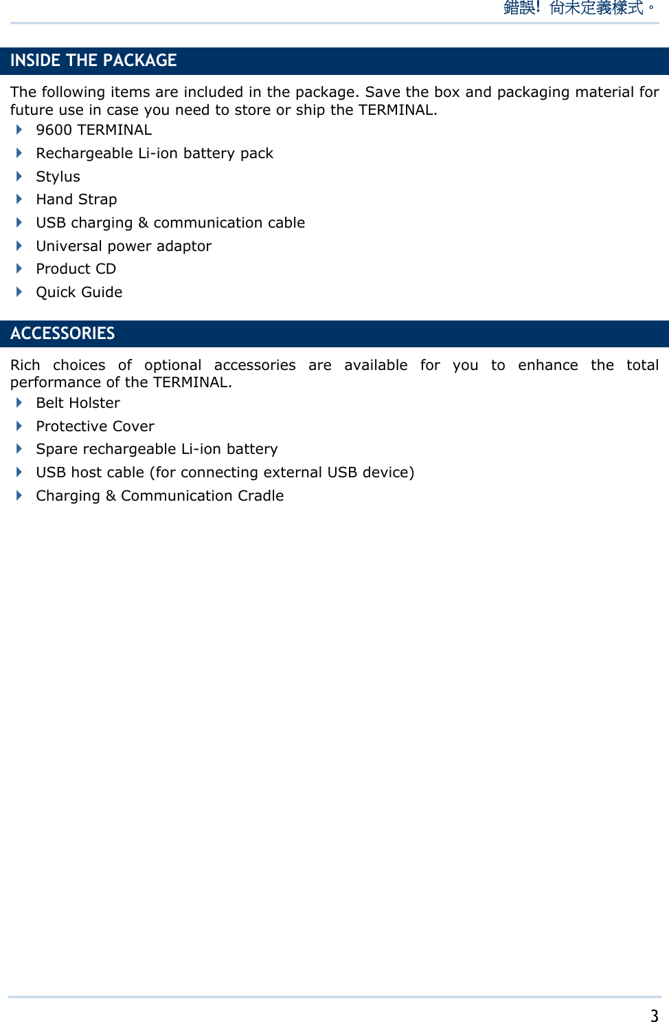
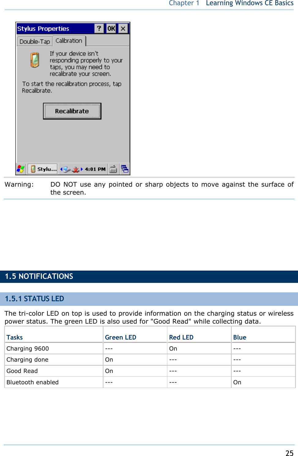
![24 9600 Mobile ComputerReference Manual 3) Select one or both of the check boxes to automatically turn off the LCD backlight when using batteries or external power. From the appropriate list, select the amount of time the device should be idle before the backlight is turned off. 4) Tap the [Advanced] button. 5) In the Settings tab (right above), you can select the luminosity of backlight when it is set to be automatically turned on by pressing any key or tapping the screen. Tap, hold, and drag the slider for AC and battery powered respectively. For more luminosity, move the slider to the right. 1.4.2 RE-CALIBRATING THE SCREEN This LCD is also a touch screen that can be calibrated through screen alignment. 1) Go to Start | Settings | Control Panel and double-tap the Stylus icon. 2) Tap the Calibration tab, and then tap the [Recalibrate] button.](https://usermanual.wiki/CipherLab/9600/User-Guide-1186622-Page-32.png)
![29 Chapter 2 Learning Windows CE Basics Tap and hold an item to see a menu that enables tasks, such as cut, copy, rename, delete, etc. Tap and drag to select multiple items. Tap on the toolbar to close an active window, a dialog box, or a running application. If the button is not displayed, press [ESC] on the physical keypad. Tap on the toolbar to save the current settings and exit the application (or minimize the window in some applications). If the button is not displayed, press [Enter] on the physical keypad. Tap on the toolbar for Windows CE Help, if there is any. IN THIS CHAPTER 2.1 Getting Started ......................................................... 29 2.2 Managing Programs ................................................... 36 2.3 Using ActiveSync ....................................................... 37 2.4 Using Windows Explorer.............................................. 41 2.5 System Reset............................................................ 43 2.6 Auto Run .................................................................. 43 2.1 GETTING STARTED When 9600 TERMINAL is fully charged, press for about 1 second to turn on the TERMINAL and wait for the Windows CE desktop to come up. If you are using the TERMINAL for the first time, there are a couple of things to do after the desktop comes up. To select your time zone and set the local time: Start | Settings | Control Panel and select Date/Time.](https://usermanual.wiki/CipherLab/9600/User-Guide-1186622-Page-37.png)
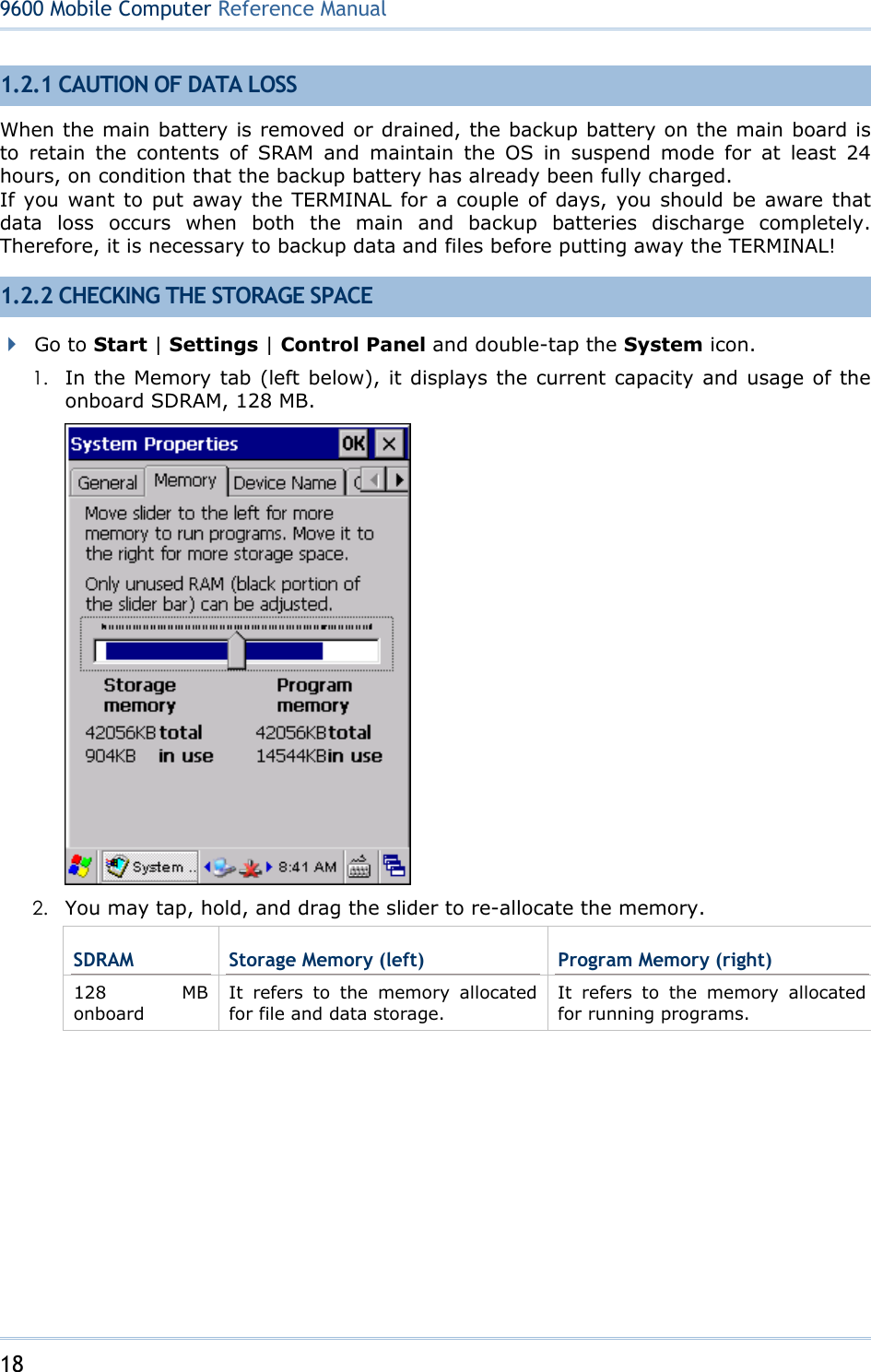
![32 9600 Mobile ComputerReference Manual SIP button Switch Task button Status icons for various connections, minimized program windows, and so on. Note: To configure different connections, go to Start | Settings and select Network and Dial-up Connections. Icon Description See Also Tap it to switch to desktop or any task, such as a running program or window. Switch Task Tap it to change the input method. Software Input Panel (SIP) It indicates external power source is connected. It indicates the amount of battery charge remaining in the main battery. The higher the green level, the more power in the main battery. It indicates the main battery status. It indicates the backup battery status. 1.1.1 Understanding the Battery Icons It indicates the current input mode of keypad. 1.3.2 Alpha Key It indicates Shift is enabled. 1.3.3 Special Key It indicates Fn is enabled. (= Function mode) 1.3.4 Function Key The USB connection for ActiveSync operation is successfully established. Double-tap it to view status. Tap [Disconnect] if necessary. 3.4 Connection Settings It indicates a specific network connection fails (= disconnected). Double-tap it to access the Wireless Information tab if there is any. Bluetooth PAN connection 802.11b/g wireless connection Ethernet connection It indicates a specific network connection has been established successfully. Double-tap it to view or renew IP Information. Bluetooth PAN connection 802.11b/g wireless connection Ethernet connection Using Bluetooth Using 802.11 Radio SIP Status Icons & Minimized Programs](https://usermanual.wiki/CipherLab/9600/User-Guide-1186622-Page-40.png)
![33 Chapter 2 Learning Windows CE Basics It provides control of the power to the 802.11b/g and GPRS modules. Double-tap any of these icons to configure the power setting. Power Management It indicates the GPRS module is enabled. See GPRS status icon below. 錯誤! 找不到參照來源。 The GPRS connection has been opened. If it fails, the icon will be gone. If the icon persists, it means the GPRS connection is successfully established. Double-tap it to view status. Tap [Disconnect] if necessary. 6.2 GPRS Connection It indicates the Wi-Fi module (802.11b/g) is enabled. The more green bars, the stronger the signal. See wireless status icons below. Summit Client Utility It provides access to the Bluetooth services. Initially, you need to go to Start | Programs | BTManager to open the Bluetooth Manager so that this icon will appear on the taskbar. Using Bluetooth It provides access to the Reader Configuration Utility. Initially, you need to double-tap the ReaderConfig.exe shortcut on the desktop so that this icon will appear on the taskbar.](https://usermanual.wiki/CipherLab/9600/User-Guide-1186622-Page-41.png)
![36 9600 Mobile ComputerReference Manual 2.2 MANAGING PROGRAMS 2.2.1 QUICK LAUNCH A PROGRAM Tap the Start button to view the Start Menu. To quick launch a program, tap it from the Programs folder. Note: Alternatively, you may tap Start and select Run to run a specific program or open a document. If you wish to quick launch a new program, add it to the Programs folder: My Device\Windows\Programs. The program will become available in the Start Menu. To add a new program or subfolder to the Programs folder, you can either use Windows Explorer or ActiveSync. Windows Explorer: to move the program by [Copy] and [Paste Shortcut]. ActiveSync on the desktop computer: to create a shortcut to the program, and place the shortcut in the Programs folder. Warning: To avoid making any changes to the program configurations by accident, we recommend you to use [Copy] and [Paste Shortcut] rather than [Cut] and [Paste]. 2.2.2 SWITCH AMONG PROGRAMS AND DESKTOP Tap to the right of the taskbar and select a running program. 2.2.3 EXIT A PROGRAM In general, the system manages memory automatically, and there is no need to exit a program in order to open another or to conserve memory. However, random access memory (SDRAM) may be used up when running too many programs. As a result, it will slow down the operation or cause program errors. In that case, you should stop one or more running programs to free memory. In order to use memory in a more efficient way, you are recommended to exit a program when it is not desired any longer. Warning: Always remember to save data or settings before you exit a program.](https://usermanual.wiki/CipherLab/9600/User-Guide-1186622-Page-44.png)
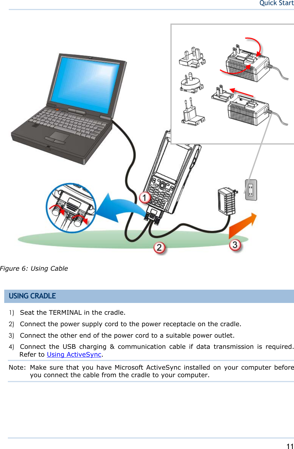
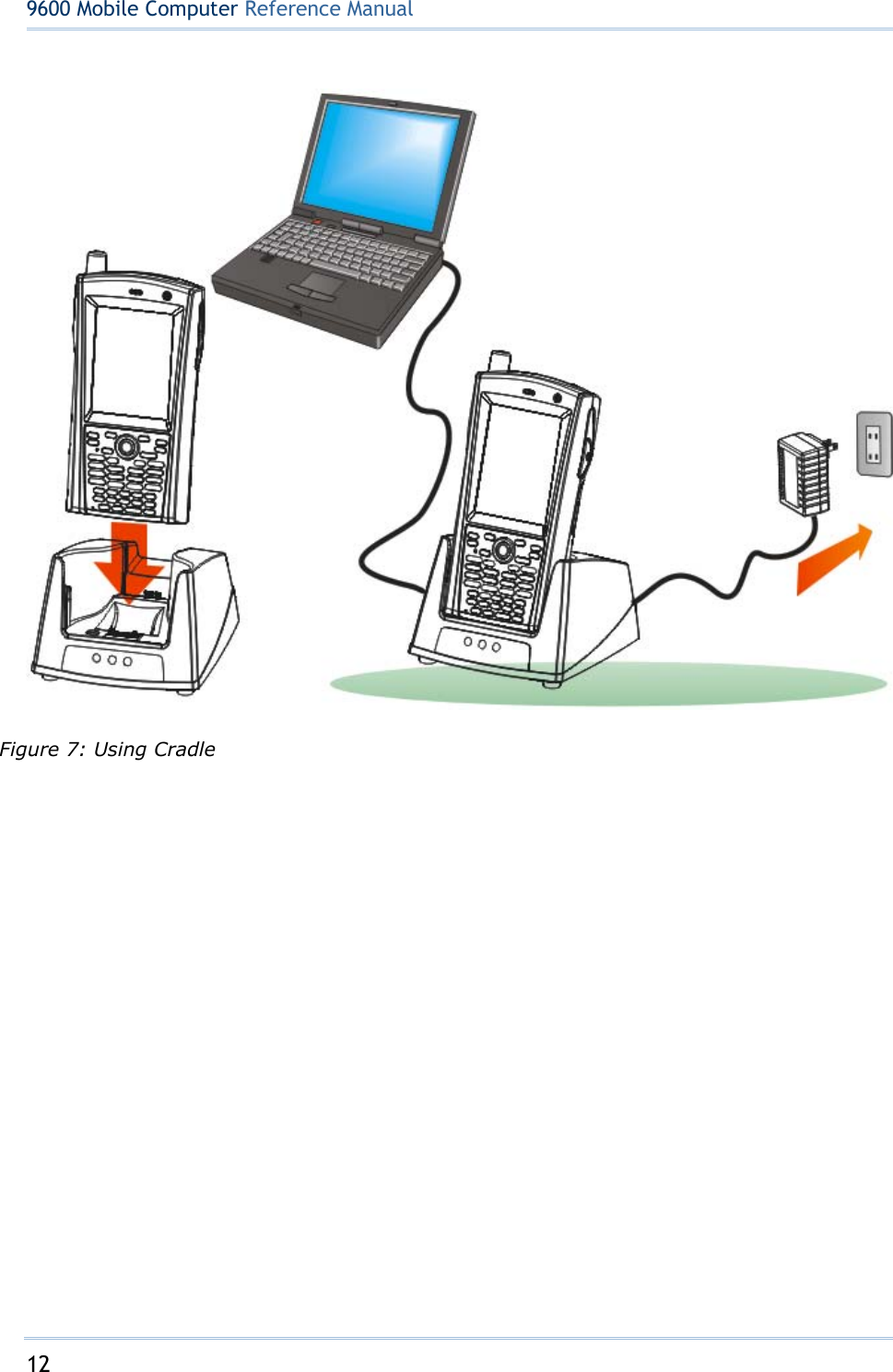
![37 Chapter 2 Learning Windows CE Basics Tap to close an active window, a dialog box, or a running application. If the button is not displayed on the toolbar, press [ESC] on the physical keypad. Tap to save the current settings and exit the application (or minimize the window in some applications). If the button is not displayed on the toolbar, press [Enter] on the physical keypad. Note: Some programs, such as the Reader Configuration Utility (ReaderConfig.exe), may create an associated icon on the taskbar. You may tap the icon and select [Exit] from the pop-up menu. 2.3 USING ACTIVESYNC ActiveSync is used to synchronize information between 9600 TERMINAL and your desktop computer, to install programs on the TERMINAL, and to backup and restore the TERMINAL. The Microsoft ActiveSync program has to be installed on your desktop computer first. To download the up-to-date version of the program, you may need to go to Microsoft's official web site for Windows Mobile devices as shown below. http://www.microsoft.com/windowsmobile/activesync/activesync45.mspx After downloading and installation, run the program. For detailed information on the program, you may click the Help menu, and then select the Microsoft ActiveSync Help. 2.3.1 SYNCHRONIZATION WITH YOUR COMPUTER 1) Follow these instructions for initial ActiveSync operation: Connect the charging & communication cable from the TERMINAL or via a cradle to your computer. Connect the power cable to a nearby power outlet. Turn on the TERMINAL or seat it in the cradle. 2) Your computer will automatically detect the USB device. Click [OK] when the connection is established.](https://usermanual.wiki/CipherLab/9600/User-Guide-1186622-Page-45.png)
![38 9600 Mobile ComputerReference Manual 3) Select which partnership to set up. If you want to synchronize data between the TERMINAL and your personal computer, select Standard Partnership; otherwise, select Guest Partnership. 4) Wait a few seconds for the TERMINAL to get connected (and synchronized if a Standard Partnership is selected). Note: For ActiveSync via Bluetooth, refer to Using Bluetooth. 2.3.2 ADD/REMOVE PROGRAMS Click [Add/Remove Programs] from the Tools Menu so that you can proceed to install a program that is designed to be used on a mobile device running Windows CE. If a user program is no longer desired, you may remove it from the system. Click [Add/Remove Programs] from the Tools Menu so that you can un-install a program that is designed to be used on a mobile device running Windows CE.](https://usermanual.wiki/CipherLab/9600/User-Guide-1186622-Page-46.png)
![39 Chapter 2 Learning Windows CE Basics Alternative to Install New Programs (Copy & Paste) You may install a new program manually. 1. When connected, open the Microsoft ActiveSync window on your desktop computer. 2. Click the Explorer button from the toolbar. 3. Navigate to the target folder, e.g. the Programs folder (\Windows\Programs), depending on where you wish to access the program. 4. Navigate through file folders on your computer to find the new program (.CAB, .EXE, etc.) 5. Right-click the program and select [copy] from the pop-up menu. 6. Back to the target folder in step 3. Right-click anywhere blank and select [Paste] from the pop-up menu. 7. On the TERMINAL, go to Start | Programs and the new program will appear. Alternative to Remove Programs (Control Panel) You may un-install a new program manually. 1. Go to Start | Settings | Control Panel and select Remove Programs. 2. Tap the name of the program that you want to delete. 3. Tap [Remove]. 4. Tap [Yes] to un-install the program. Note: If the program does not appear in the list of installed programs, you may use Windows Explorer to locate it. Tap and hold the program to select [Delete] from the pop-up menu.](https://usermanual.wiki/CipherLab/9600/User-Guide-1186622-Page-47.png)
![40 9600 Mobile ComputerReference Manual 2.3.3 EXPLORE DEVICE Add a Program to Start Menu 1. When connected, open the Microsoft ActiveSync window on your desktop computer. 2. Click the Explorer button from the toolbar. 3. Navigate through file folders to find the program you desire. 4. Right-click the program and select [Create Shortcut] from the pop-up menu. 5. Right-click the shortcut and select [Cut] from the pop-up menu. 6. Navigate to the Programs folder – My Device\Windows\Programs. 7. Right-click anywhere blank on the window and select [Paste] from the pop-up menu. The new program will be added to the Programs folder. 8. On the TERMINAL, go to Start | Programs and the new program will appear now. Note: [Create Shortcut], [Cut], and [Paste]: The same result can be performed by [Copy] and [Paste Shortcut]. Create a New Folder 1. When connected, open the Microsoft ActiveSync window on your desktop computer. 2. Click the Explorer button from the toolbar. 3. Navigate to the target folder where you wish to create a new folder. 4. Right-click anywhere blank on the window and select [New Folder] from the pop-up menu. A subfolder will be created. 2.3.4 BACKUP/RESTORE](https://usermanual.wiki/CipherLab/9600/User-Guide-1186622-Page-48.png)
![41 Chapter 2 Learning Windows CE Basics To best protect your work, you should regularly back up information on your TERMINAL. You can perform a backup by during the ActiveSync operation. The backup file is stored on your desktop computer. Note: The CipherLab Backup Utility is provided for the same purposes, and will save the backup file to the DiskOnChip folder. 2.4 USING WINDOWS EXPLORER 2.4.1 ADD A PROGRAM TO START MENU 1) Go to Start | Programs and select Windows Explorer. 2) Navigate through file folders to find the program you desire. 3) Tap and hold the program to select [Copy] from the pop-up menu. 4) Navigate to the Programs folder – My Device\Windows\Programs.](https://usermanual.wiki/CipherLab/9600/User-Guide-1186622-Page-49.png)
![42 9600 Mobile ComputerReference Manual 5) Tap and hold anywhere blank on the screen to select [Paste Shortcut] from the pop-up menu. The new program will be added to the Programs folder. 6) Go to Start | Programs and the new program will appear now. 2.4.2 CREATE A NEW FOLDER 1) Go to Start | Programs and select Windows Explorer. 2) Navigate through file folders to find where you wish to create a new folder. 3) Tap and hold anywhere blank on the window and select [New Folder] from the pop-up menu. A subfolder will be created.](https://usermanual.wiki/CipherLab/9600/User-Guide-1186622-Page-50.png)
![43 Chapter 2 Learning Windows CE Basics 2.5 SYSTEM RESET Reset the TERMINAL when it stops responding to input. Software Reset: Simply press the [Reset] button. Hardware Reset: Press the [Reset] button and at the same time. Warning: Never perform hardware reset unless software reset cannot solve your problems. 2.5.1 SOFTWARE RESET (WARM REBOOT) Software reset, also known as a warm boot, will restart the TERMINAL and keep all the saved files. To perform software reset, use the stylus to press the [Reset] button. During operation, the removal of main battery will start software reset too. Warning: Data loss may occur when files are not properly closed before software reset. 2.5.2 HARDWARE RESET (COLD REBOOT) Hardware reset, also known as a cold boot, will restart the TERMINAL too. However, it performs a full restore of the TERMINAL to its factory settings and initializes SDRAM. To perform hardware reset, press and [Reset] button at the same time. Data and program files stored in SDRAM will be erased after hardware reset. But you can restore data that is previously synchronized with your computer by performing an ActiveSync operation, or backed up by using CipherLab Backup Utility. Warning: Only the files stored in the Flash File System are retained during hardware reset. 2.6 AUTO RUN Upon hardware or software reset, the OS shall automatically execute AutoRun.exe and/or AutoRun.ini if any of the two files can be found in the “\DiskOnChip” folder or on microSD card. If AutoRun.exe exists Upon cold boot, the OS shall automatically execute AutoRun.exe Upon warm boot, the OS shall automatically execute AutoRun.exe If AutoRun.ini exists Upon cold boot, the OS shall automatically check the contents of AutoRun.ini and execute them (if there is any).](https://usermanual.wiki/CipherLab/9600/User-Guide-1186622-Page-51.png)
![49 Chapter 3 Configuring 9600 TERMINAL Items Description In the [Certificates] dialog box, you may view or modify digital certificates that some application use to establish trust for secure connections. In the [Date/Time] dialog box, you may change date, time, and time zone settings. In the [Dialing Properties] dialog box, you may configure settings for modem communications, such as the GPRS modem. In the [Display Properties] dialog box, Background tab: Select an image for the background. Appearance tab: Select a desired color scheme for windows, dialog boxes, and items. Backlight tab: Specify for how long the TERMINAL is idle and then the backlight will be automatically turned off while on battery power and external power respectively. Tap the [Advanced] button to move the slider and adjust the brightness of the LCD backlight when it is set to be automatically turned on once a key is pressed or you tap the touch screen. In the [Input Panel Properties] dialog box, you may configure how the Soft Input Panel (SIP) works.](https://usermanual.wiki/CipherLab/9600/User-Guide-1186622-Page-57.png)
![50 9600 Mobile ComputerReference Manual In the [Internet Options] dialog box, you may configure how the TERMINAL connects to the Internet. Connect an external keyboard to the TERMINAL or cradle via the USB host cable. In the [Keyboard Properties] dialog box, you may configure settings for character repeat. Connect a mouse to the TERMINAL or cradle via the USB host cable. In the [Mouse Properties] dialog box, you may configure and test your double-click settings. In the [Network and Dial-up Connections] window, you may configure settings for the TERMINAL connects to a network directly or through a modem. Alternatively, you may tap Start | Settings | Network and Dial-up Connections. USB Connection (ActiveSync via USB cable) GPRS (through a GPRS modem) AX88772 (via Ethernet Cradle) SDCCF10G1 (via 802.11b/g) BTPAN (via Bluetooth) In the [Owner Properties] dialog box, Identification/Notes tab: Type your contact information or notes. Network ID tab: Type the user name, password, and domain name used to log on to the remote network. In the [Password Properties] dialog box, you may apply password protection at power-on to limit access to the TERMINAL. In the [PC Connection Properties] dialog box, you may disable the direct connection between the TERMINAL and a desktop computer. By default, the TERMINAL is allowed to directly connect to a desktop computer via the USB or RS-232 charging & communication cable. Alternatively, you may tap Start | Settings | Network and Dial-up Connections and select USB Connection. You may change to use Bluetooth if ActiveSync via Bluetooth has been enabled in the Bluetooth Manager In the [Power Properties] dialog box, Battery tab: You may view the current status of main and backup batteries. Schemes tab: You may configure the power scheme and switching. Device Status tab: You may view the devices that are consuming power. In the [Regional and Language Settings] dialog box, Region tab: You may customize the appearance and formatting to your geographic region. Language tab: By default, it is set to English (United States). Input tab: By default, it is set to English (United States)-US.](https://usermanual.wiki/CipherLab/9600/User-Guide-1186622-Page-58.png)
![51 Chapter 3 Configuring 9600 TERMINAL In the [Remove Programs] dialog box, you may remove any program that is installed earlier. In the [Storage Properties] dialog box, Storage Manager tab: You may reformat the available storage device, either the DiskOnChip folder or storage card. Actions include “Dismount the storage device”, “Format the storage device”, and “Set up disk partitions”. The Storage Manager is for the use of system administrators only. In the [Stylus Properties] dialog box, Double-Tap tab: You may configure and test your double-tap settings. Calibration tab: You may need to re-calibrate the touch screen if it is not responding properly to your taps. In the [System Properties] dialog box, General tab: You may view the system information. Memory tab: You may move the slider and adjust the SDRAM allocation. Device Name tab: You may type a name and description for identifying the TERMINAL. Copyrights tab: You may view the important statements on copyrights. Client access licenses (CALs) issued by the Terminal Server license server allow clients to connect to the terminal server. Use Remote Desktop Connection to log onto a Windows Terminal Server or a computer remotely. You may access all of the programs, files, and network resources on the remote host or terminal server. In the [Volume & Sounds Properties] dialog box, Volume tab: You may move the slider and adjust the volume and select to play sounds for Events, Applications or Notifications. Sounds tab: You may configure sounds for different Windows events. Refer to 4.2 Summit Client Utility.](https://usermanual.wiki/CipherLab/9600/User-Guide-1186622-Page-59.png)
![52 9600 Mobile ComputerReference Manual 3.4 CONNECTION SETTINGS There are two ways to access the connections settings: Go to Start | Settings | Control Panel and select Network and Dial-up Connections. Go to Start | Settings | Network and Dial-up Connections. Connections Description This is a shortcut to USB Connection, and the selected interface is USB for factory setting. This connection is reflected in the control panel for direct PC connection: Start | Settings | Control Panel | The USB connection is specifically for performing the ActiveSync operation via the USB or RS-232 charging & communication cable. Generally, it will automatically establish the connection and start the ActiveSync operation when you seat the TERMINAL in the cradle. To stop the ActiveSync operation, simply remove the TERMINAL. Alternatively, you may double-tap the status icon from the taskbar and tap [Disconnect]. When connected, the status icon will appear on the taskbar. When disconnected, this icon will disappear. Ignore [Properties] as the associatedsettings will not take effect.](https://usermanual.wiki/CipherLab/9600/User-Guide-1186622-Page-60.png)
![53 Chapter 3 Configuring 9600 TERMINAL This is the control of networking over USB cable. It is enabled automatically when the TERMINAL is connected to PC via USB cable. This is the control of Ethernet module AX88772. It is enabled automatically when the TERMINAL is seated in the Ethernet Cradle. When available, the connection status icon will appear on the taskbar. When connected, this icon will become . When disconnected, this icon will become again. This is a shortcut to GPRS connection. Note that the power to the /PRS module must be turned on through Power Management for establishing a connection. When GPRS power is turned on, the icon will become . When connected to a GPRS modem, the status icon will appear on the taskbar. When disconnected, this icon will disappear. This is the control of 802.11b/g module for wireless local area networking (WLAN) connection, which is not available until the power to 802.11b/g module is turned on through Power Management . When available, the connection status icon will appear on the taskbar. When connected, this icon will become . When disconnected, this icon will become again. This is the control of Bluetooth module for wireless personal area networking (WPAN) connection, which is not available until the Bluetooth Manager is executed. When available, the connection status icon will appear on the taskbar. When connected, this icon will become . When disconnected, this icon will become again. Note: By default, DHCP is enabled for networking. Instead of using DHCP, select [Properties] and specify a static IP address to the TERMINAL. Only change these settings according to your network administrator's instructions. Toolbar Items Description Remarks Tap this button to open the Connection menu. The available options depend on the connection you select. Tap and hold the icon of a desired connection type. Then, select an option from](https://usermanual.wiki/CipherLab/9600/User-Guide-1186622-Page-61.png)
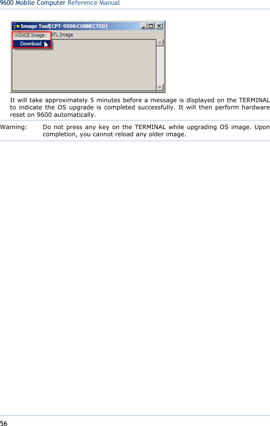
![54 9600 Mobile ComputerReference Manual Tap this button to toggle on/off the connection you select. The toggle is used for Enable/Disable or Connect/Disconnect. Tap this button to delete the connection you select. Tap this button to view the properties of the connection you select. its associated menu. 3.5 UPGRADING OS IMAGE You can upgrade the OS image on your TERMINAL either via microSD card or run the program "DLDR.exe" on the desktop of your computer. Please contact your sales representative for the OS upgrade utility "DLDR.exe". The OS upgrade should be performed with great caution because everything on the TERMINAL will be erased. Warning: Backup user-installed applications and files to your computer first. 3.5.1 SD DOWNLOAD The SD download method allows upgrading image from your microSD storage card. 1) Copy the image file to the root directory of your microSD storage card (“\SD Card”), and rename it to “NK.nb0”. 2) Press [Reset] + to perform hardware reset on 9600. 3) Press + to enter SD Download mode. It will take approximately 5 minutes before a message is displayed on the TERMINAL to indicate the OS upgrade is completed successfully. 4) Press [Reset] + to perform hardware reset on 9600 again. Warning: Do not press any key on the TERMINAL while upgrading OS image. Upon completion, you cannot reload any older image. 3.5.2 RUN DLDR.EXE 1) Install Microsoft ActiveSync on your computer. For initial ActiveSync operation, refer to Using ActiveSync for details. Now, you must disable the ActiveSync operation as shown below.](https://usermanual.wiki/CipherLab/9600/User-Guide-1186622-Page-62.png)
![55 Chapter 3 Configuring 9600 TERMINAL 2) Run the Image Tool “DLDR.exe” on your computer. 3) Press [Reset] + to perform hardware reset on 9600. 4) Seat 9600 in the cradle. 5) Press + on 9600 to start the download process. It will try to connect to your computer. 6) In the Image Tool, it will show 9600 has been connected successfully. Go to WINCE Image | Download, and select the desired image file (*.nb0).](https://usermanual.wiki/CipherLab/9600/User-Guide-1186622-Page-63.png)
![59 Summit Client Utility, also referred to as SCU, lets you configure and connect to network wirelessly. IN THIS CHAPTER 4.1 Turn On Wi-Fi Power .................................................. 59 4.2 Summit Client Utility .................................................. 60 4.1 TURN ON WI-FI POWER 1) Double-tap the associated icon on the taskbar to access Power Management. 2) Select [Wi-Fi Power ON] and tap . Warning: When both GPRS and 802.11b/g are enabled on battery power, the main battery charge will drop down substantially. 3) It takes several seconds to turn on the power to module and install the driver. The Summit system tray icon will appear as shown below: The icon indicates that 802.11b/g power is turned on, and the green bars indicate the wireless signal strength. The more the bars, the stronger the signal. Double-tap any of these icons to access Summit Client Utility. Chapter 4USING 802.11 RADIO](https://usermanual.wiki/CipherLab/9600/User-Guide-1186622-Page-67.png)
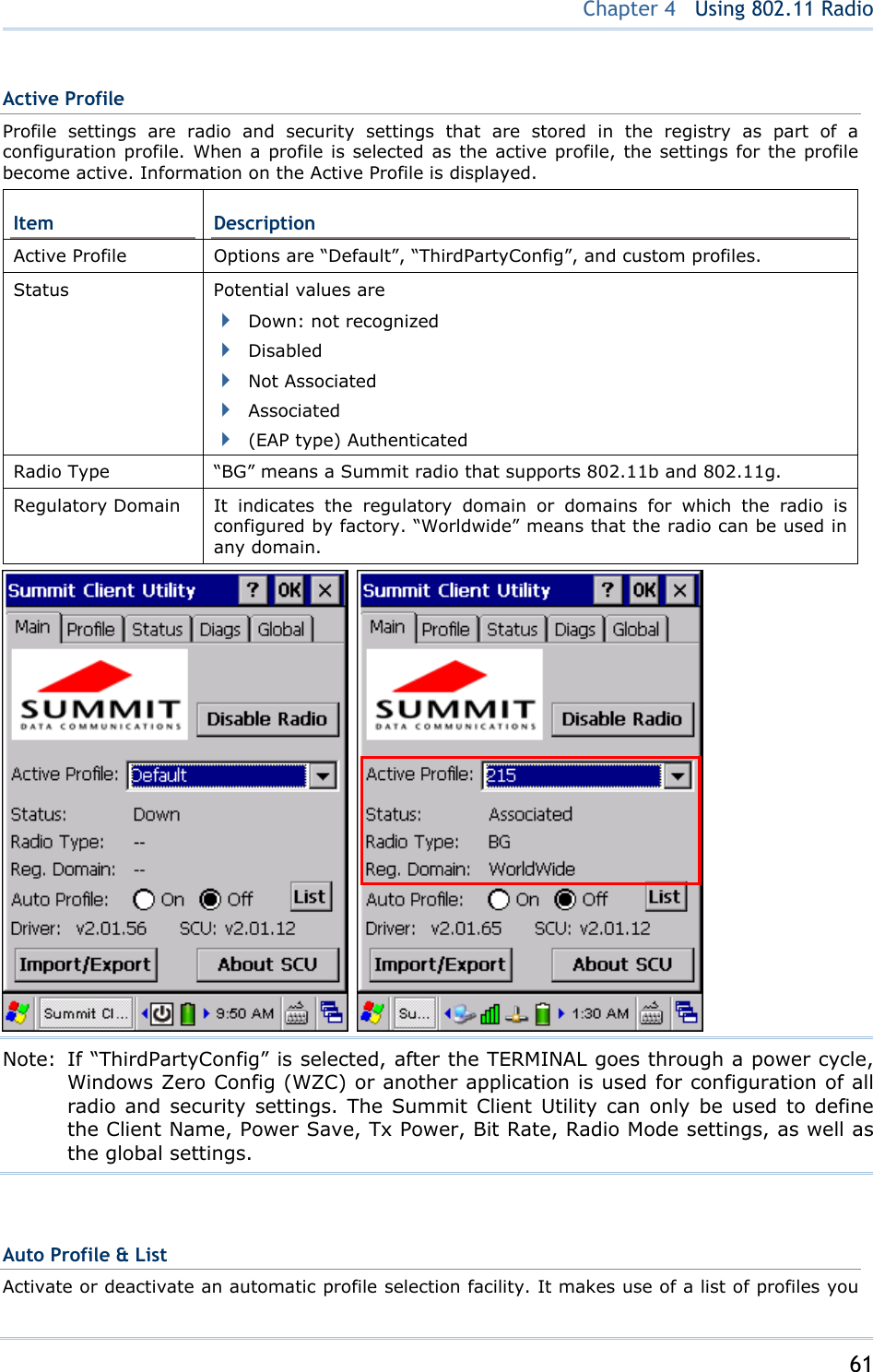
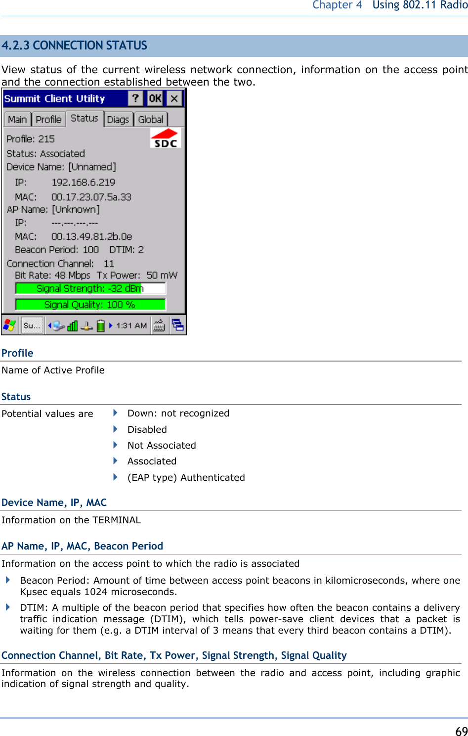
![60 9600 Mobile ComputerReference Manual 4.2 SUMMIT CLIENT UTILITY Profile settings are radio and security settings that are stored in the registry as part of a configuration profile. When a profile is selected as the active profile, the settings for the profile become active. You may create, rename, edit, and delete profiles, as well as alter global settings that apply to every profile or to SCU itself. For more detail on the profile settings, please go to http://www.summitdatacom.com/documentation.htm for more documents, such as http://www.summitdatacom.com/Documents/Summit_Users_Guide_2.01_200805.htm http://www.summitdatacom.com/Documents/Summit_Quick_Start_Guide_2.01.pdf 4.2.1 MAIN SETTINGS Enable/Disable Radio Tap [Disable Radio] to turn off wireless signal. The signal bars of the Summit Client Utility icon will become to indicate no signal. The connection status icon will become . Note: You may need to turn off the wireless power or simply stop the wireless signals at times, in order to conserve battery power, or in situations where the use of radio is prohibited, such as on airplanes, in hospitals, etc.](https://usermanual.wiki/CipherLab/9600/User-Guide-1186622-Page-68.png)
![62 9600 Mobile ComputerReference Manual created. If such list does not exist, tap [List] to select the profiles in use. When the facility is active and the radio is not associated to an access point, SCU runs through the list and tries each profile one by one until the radio associates to an access point using the values in a profile. The profile becomes the Active Profile and remains so until the radio disassociates or disconnects from the network. Import/Export It is made easy to clone the profile(s) and global settings from a master TERMINAL to others. Tap [Import/Export] and select the task to perform: “Import from” or “Export to”.](https://usermanual.wiki/CipherLab/9600/User-Guide-1186622-Page-70.png)
![63 Chapter 4 Using 802.11 Radio By default, the file name is “SummitSettings.sdc”. Export to: Export global settings, all standard SCU profiles, and the special profile “ThirdPartyConfig” from the SCU area of the registry to a file. Import from: Import global settings, all standard SCU profiles, and the special profile “ThirdPartyConfig” from a file (created using the Export facility above) to the SCU area of registry. If you are importing a file and select [Add to existing], then the imported information will be merged with the information that was in the registry previously. If you select [Replace] instead, then the imported information will overwrite the information that was in the registry previously. Default and custom profiles are included.](https://usermanual.wiki/CipherLab/9600/User-Guide-1186622-Page-71.png)
![64 9600 Mobile ComputerReference Manual 4.2.2 PROFILE EDITING Any changes made to a profile will not be saved until you tap [Commit]. Edit Profile By default, information of the profile “Default” is displayed. Select a profile from the drop-down menu and configure the Radio settings, Encryption, EAP Type, and so on. For example, select “SSID” from the Radio list and enter a preferred name for the network. Radio Configuration SSID Service Set Identifier (SSID) for WLAN to which the radio will connect If no SSID is specified, the radio will only associate to an access point that broadcasts its SSID. Value: A string of up to 32 characters Default: None Client Name Name assigned to the TERMINAL with Summit radio installed Value: A string of up to 16 characters Default: None Power Save Power save mode for radio Value: CAM Constantly awake mode Maximum Maximum power savings Fast Fast power save mode Default: Fast Tx Power Transmit power that can be overridden by Cisco AP if CCX global setting iON dAPdfi i t itflitl l](https://usermanual.wiki/CipherLab/9600/User-Guide-1186622-Page-72.png)
![66 9600 Mobile ComputerReference Manual User: Username or Domain\Username (up to 64 characters) Password (up to 32 characters) EAP-FAST Credentials values for EAP-FAST User: Username or Domain\Username (up to 64 characters) Password (up to 32 characters) PAC Filename (up to 32 characters) PAC Password (up to 32 characters) PEAP-MSCHAP PEAP-GTC EAP-TLS Credentials values for PEAP-MSCHAP, PEAP-GTC, EAP-TLS User: Username or Domain\Username (up to 64 characters) Password (up to 32 characters) “Validate server” checkbox: Select this if using a CA certificate to validate an authenticate server. When selected, enter a certificate filename in the CA Cert field or select the “Use MS store” checkbox. CA Cert: Filename of root certificate authority (CA) digital certificate (up to 32 characters); leave blank if the “Use MS store” checkbox is selected. “Use MS store” checkbox: Select this if the Microsoft certificate store should be used for a CA certificate. This is applicable only when “Validate server” is in use. Additional values for EAP-TLS User Cert: Tap the […] button to select a user (or client) certificate from the Microsoft certificate store. You may not enter a filename because the user certificate must reside in the Microsoft certificate store. When you browse for a certificate, the pop-up box shows two fields, “Issued By” and “Issued to”. Priv. key pwd: Password for user certificate (up to 32 characters) Default: None for both EAP type and credentials New](https://usermanual.wiki/CipherLab/9600/User-Guide-1186622-Page-74.png)
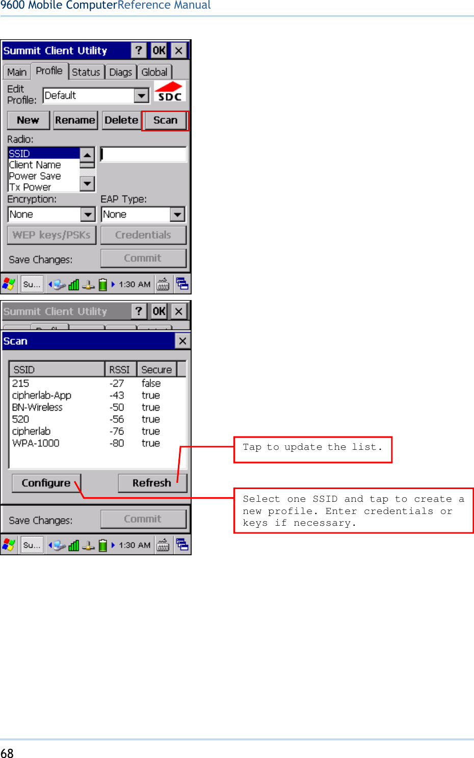
![67 Chapter 4 Using 802.11 Radio Tap [New] and enter a unique name for this profile. Up to 32 characters are allowed. Configure the Radio settings, Encryption, EAP Type, and so on. Define up to 20 profiles, not including the special profile “ThirdPartyConfig”. Rename Select a profile from the drop-down menu and tap [Rename]. Enter a unique name for this profile. Up to 32 characters are allowed. Delete Select a profile from the drop-down menu and tap [Delete]. You cannot delete the Active Profile. Scan Tap [Scan] to view a list of access points that are broadcasting their SSIDs. You may sort the list by tapping the column headers. Select one and create a profile for it. Item Description SSID Service Set Identifier (SSID) RSSI Received Signal Strength Indication (RSSI) Secure It indicates whether data encryption is in use: true or false](https://usermanual.wiki/CipherLab/9600/User-Guide-1186622-Page-75.png)
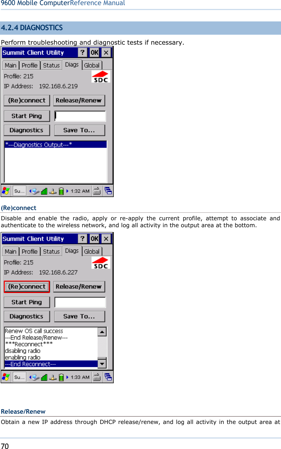
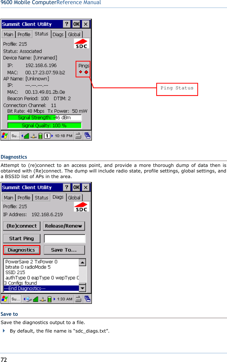
![71 Chapter 4 Using 802.11 Radio the bottom. Start Ping Start a continuous ping to the address in the edit box next to the button. Once the button is tapped, its name and function will change to [Stop Ping]. Pings will continue until you tap the [Stop Ping] button, move to an SCU window other than Diags or Status, exit SCU, or remove the radio. Also, it log all activity in the output area at the bottom. When a ping initiated on the Diags window is active, the Status window displays a ping indicator consisting of two “lights” that take turns to show green (for a successful ping) or red (for an unsuccessful ping).](https://usermanual.wiki/CipherLab/9600/User-Guide-1186622-Page-79.png)
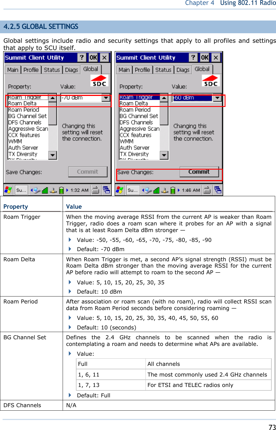
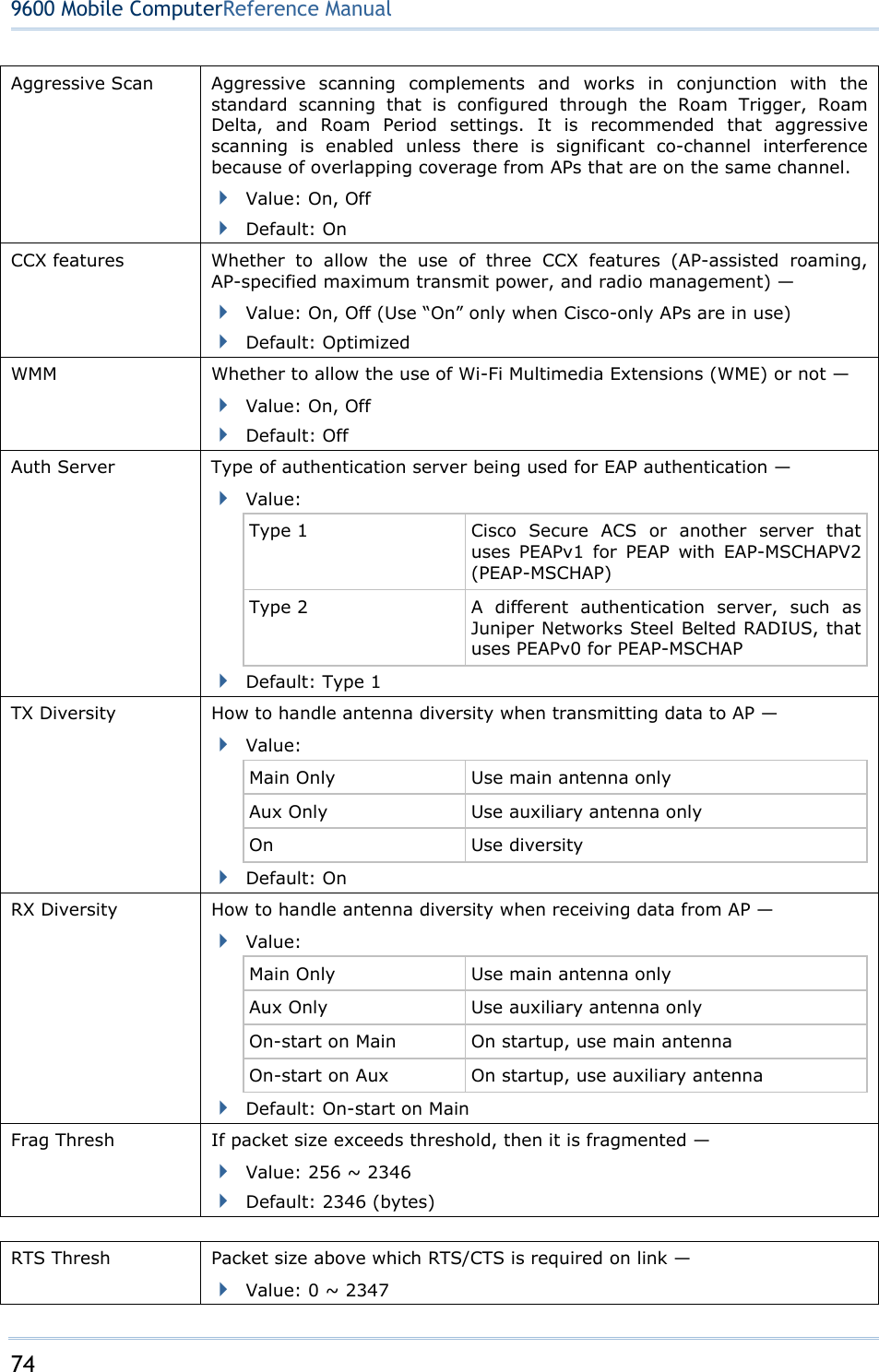
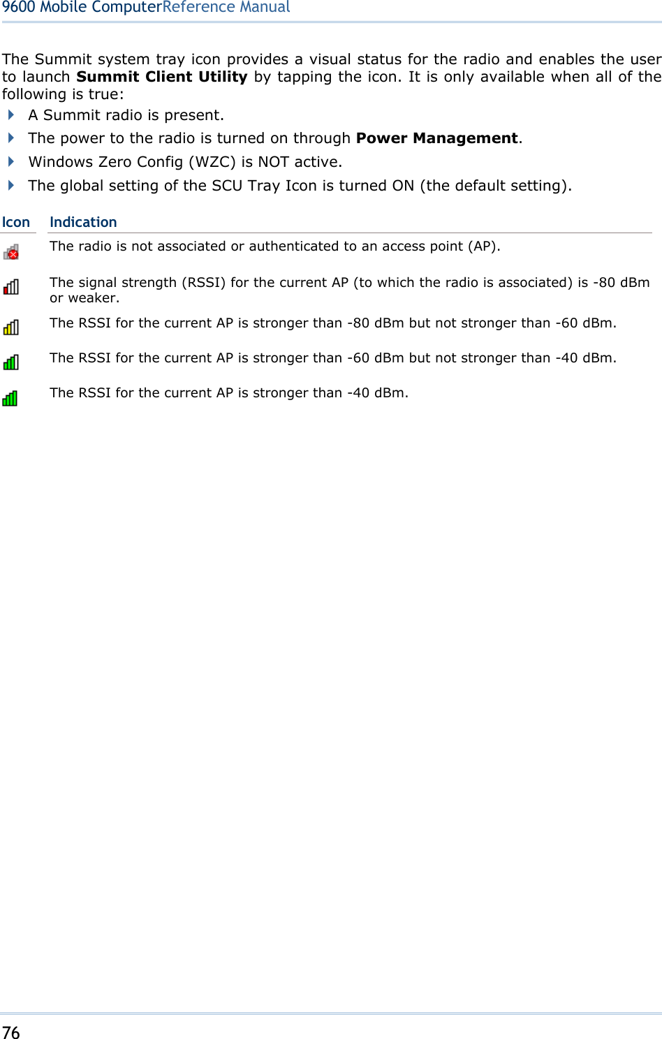
![75 Chapter 4 Using 802.11 Radio Default: 2347 (bytes) LED N/A Tray Icon Whether to enable the system tray icon or not — Value: On, Off Default: On Hide Passwords Whether to hide the passwords and other sensitive information, such as WEP keys, in SCU as well as EAP authentication dialog boxes — Value: On, Off Default: Off Admin Password N/A Auth Timeout (s) Specifies how long it will wait for an EAP authentication request to succeed or fail. If authentication credentials are specified in the active profile and the authentication times out, then association will fail. If authentication credentials are not specified in the active profile and the authentication times out, then the user will be required to enter credentials again. Value: 3 ~ 60 Default: 8 (seconds) Certs path File path where the certificate for EAP authentication is stored Value: A valid directory path of up to 64 characters Default: Depends on device Ping Payload The amount of data to be transmitted on a pin — Value: 32, 64, 128, 256, 512, 1024 Default: 32 (bytes) Ping Timeout (ms) The amount of time that elapses without a response before ping request is considered a failure — Value: 0 ~ 30000 Default: 5000 (milliseconds) Ping Delay (ms) The amount of time that elapses between successive ping requests — Value: 0 ~ 7200000 Default: 1000 (milliseconds) Note: SCU stores values in the registry. The purpose of “Custom” is to prevent SCU from overriding a change to the registry that was made manually. Selecting “Custom” has no real effect! (1) If SCU displays a value of “Custom” for a global setting, then the operating system registry has been edited to include a value that is not available for selection on the Global window. (2) If SCU displays a value other than “Custom” and you select the value of “Custom” and tap [Commit], then SCU reverts to the value that is displayed before you selected “Custom”. 4.2.6 SUMMIT SYSTEM TRAY ICON](https://usermanual.wiki/CipherLab/9600/User-Guide-1186622-Page-83.png)
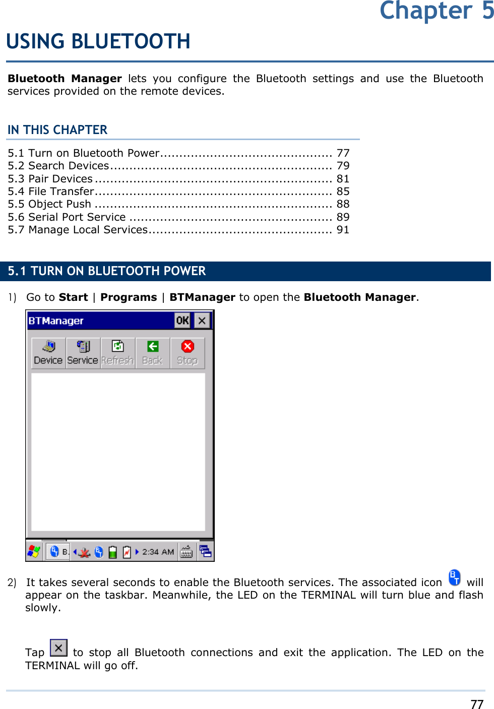
![78 9600 Mobile ComputerReference Manual Note: You may need to stop using the Bluetooth services at times, in order to conserve battery power, or in situations where the use of radio is prohibited, such as on airplanes, in hospitals, etc. 5.1.1 BLUETOOTH TOOLBAR Buttons Description Tap this button to view the Bluetooth devices discovered during this session. If you tap the button for the first time, it will start the inquiry process to discover nearby Bluetooth devices. Tap this button to view the Bluetooth services provided on 9600. By default, File Transfer and Object Push services are made available, and therefore, displayed along with a plug icon “ ”. To change properties of a service, tap and hold it to select [Change Local Path] from the pop-up menu. Local Path Bluetooth Service on 9600 \Temp\Ftp File Transfer \My documents Object Push Tap this button to stop inquiring, disconnect a connection or unload a service. Tap this button to refresh the device list. Tap this button to restore the previous window.](https://usermanual.wiki/CipherLab/9600/User-Guide-1186622-Page-86.png)
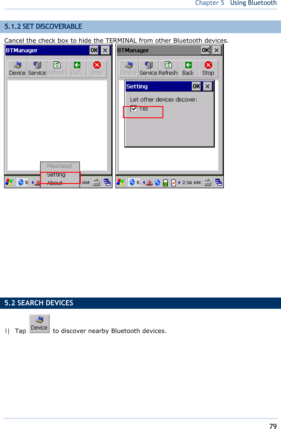
![81 Chapter 5 Using Bluetooth 5.3 PAIR DEVICES 5.3.1 IDENTIFY REMOTE DEVICE From the device list, tap and hold the desired device to select [MAC address] from the pop-up menu. 5.3.2 PAIR When authentication is enabled on the remote device, you will have to exchange a passkey (= pair) with it before starting a connection.](https://usermanual.wiki/CipherLab/9600/User-Guide-1186622-Page-89.png)
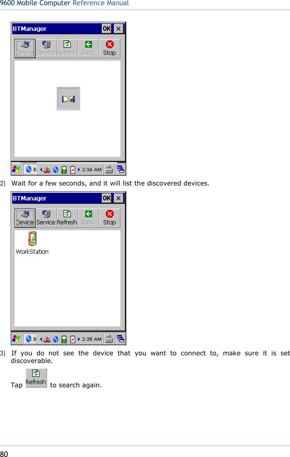
![82 9600 Mobile ComputerReference Manual 1) From the device list, tap and hold the desired device to select [Pair] from the pop-up menu. 2) Enter the PIN code that is specified on the remote device. (right above) 3) Once paired successfully, the paired device will be displayed along with a lock icon "".](https://usermanual.wiki/CipherLab/9600/User-Guide-1186622-Page-90.png)
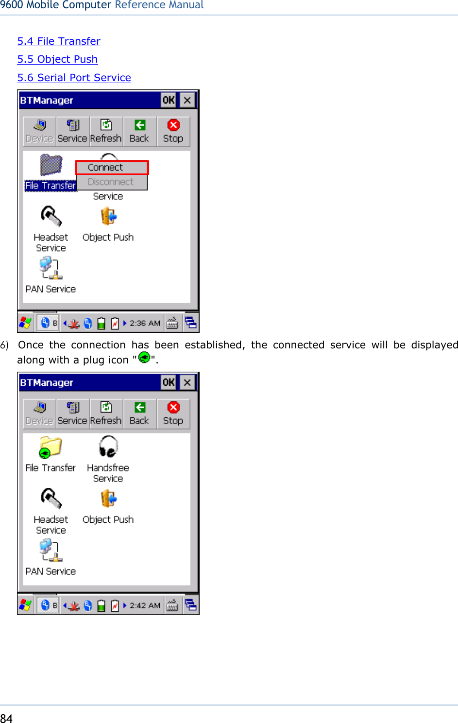
![83 Chapter 5 Using Bluetooth 4) Double-tap the remote device to find out the available Bluetooth services. 5) Tap and hold a desired Bluetooth service. Select [Connect] or [Push File] from the pop-up menu. Refer to the following sections:](https://usermanual.wiki/CipherLab/9600/User-Guide-1186622-Page-91.png)
![85 Chapter 5 Using Bluetooth 5.3.3 UNPAIR From the device list, tap and hold the desired device to select [Unpair] from the pop-up menu. Note: The TERMINAL must be unpaired on the remote device as well. For example, remove it from the device list on PC. (Both devices must be unpaired!) 5.4 FILE TRANSFER 1) Tap and hold the File Transfer service.](https://usermanual.wiki/CipherLab/9600/User-Guide-1186622-Page-93.png)
![86 9600 Mobile ComputerReference Manual 2) Select [Connect] (and assign COM port if necessary). 5.4.1 UPLOAD A FILE 3) Tap and hold anywhere blank to select [Put File] from the pop-up menu. 4) Choose the file you wish to upload to the remote device. 5) The TERMINAL will start uploading the file to the remote device.](https://usermanual.wiki/CipherLab/9600/User-Guide-1186622-Page-94.png)
![87 Chapter 5 Using Bluetooth 5.4.2 DOWNLOAD A FILE 6) Tap and hold a desired file to select [Get File] from the pop-up menu. The TERMINAL will start downloading the file from the remote device.](https://usermanual.wiki/CipherLab/9600/User-Guide-1186622-Page-95.png)
![88 9600 Mobile ComputerReference Manual 5.5 OBJECT PUSH 1) Tap and hold the Object Push service. 2) Select [Push file] to send a file. 3) Choose a file you wish to send. 4) The TERMINAL will start sending the file.](https://usermanual.wiki/CipherLab/9600/User-Guide-1186622-Page-96.png)
![89 Chapter 5 Using Bluetooth 5.6 SERIAL PORT SERVICE 5.6.1 SERIAL PORT SERVICE 1) Tap and hold the Serial Port Service. 2) Select [Connect] (and assign COM port if necessary).](https://usermanual.wiki/CipherLab/9600/User-Guide-1186622-Page-97.png)
![90 9600 Mobile ComputerReference Manual 3) Once the connection has been established, the connected service will be displayed along with a plug icon " ". 5.6.2 BLUETOOTH ACTIVESYNC For ActiveSync via Bluetooth, tap and hold Serial Port Service to select [ActiveSync via BT] from the pop-up menu.](https://usermanual.wiki/CipherLab/9600/User-Guide-1186622-Page-98.png)
![91 Chapter 5 Using Bluetooth 5.7 MANAGE LOCAL SERVICES By default, File Transfer and Object Push services are made available, and therefore, displayed along with a plug icon “ ”. 5.7.1 FILE TRANSFER Change Local Path You can change the FTP folder. Tap and hold it to select [Change Local Path] from the pop-up menu.](https://usermanual.wiki/CipherLab/9600/User-Guide-1186622-Page-99.png)
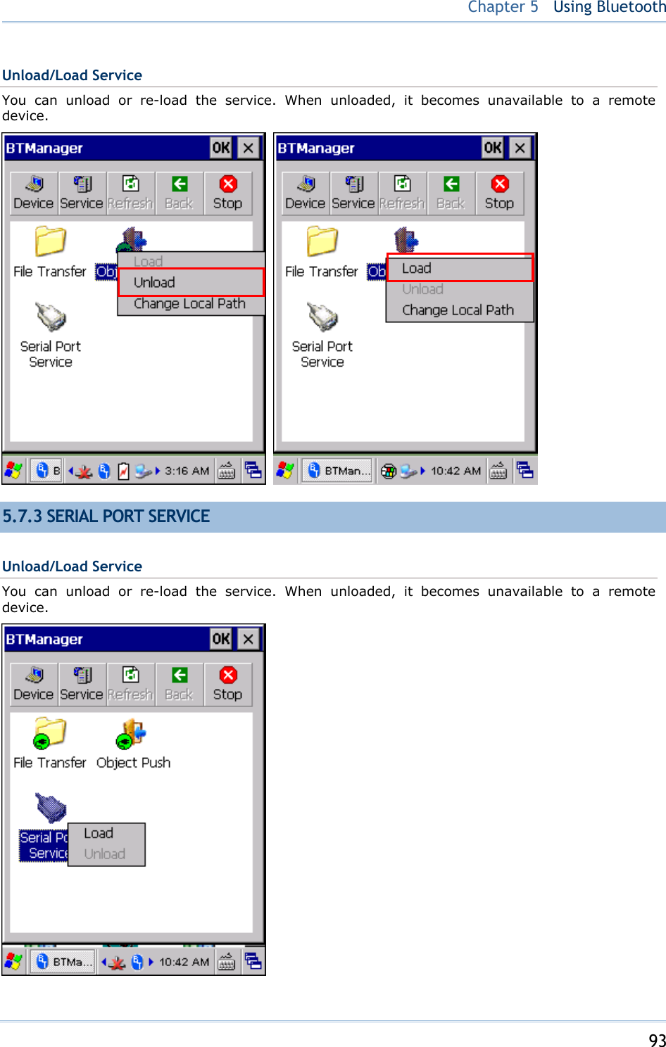
![92 9600 Mobile ComputerReference Manual Unload/Load Service You can unload or re-load the service. When unloaded, it becomes unavailable to a remote device. 5.7.2 OBJECT PUSH Change Local Path You can change the exchange folder for Object Push. Tap and hold it to select [Change Local Path] from the pop-up menu.](https://usermanual.wiki/CipherLab/9600/User-Guide-1186622-Page-100.png)
![95 9600 TERMINAL allows making phone calls or connecting to network over General Packet Radio Service (GPRS). Insert SIM card before turning on the power to GPRS module. Refer to Inserting SIM Card. Warning: When both GPRS and 802.11b/g are enabled on battery power, the main battery charge will drop down substantially. IN THIS CHAPTER 6.1 Turn On GPRS Power............................................... 95 6.2 GPRS Connection....................................................... 97 錯誤! 找不到參照來源。 ............................... 錯誤! 尚未定義書籤。 6.1 TURN ON GPRS POWER 1) Double-tap the associated icon on the taskbar to access Power Management. 2) Select [ GPRS Power ON] and tap . You may need to turn off the wireless power or simply stop the wireless signals at times, in order to conserve battery power, or in situations where the use of radio is prohibited, such as on airplanes, in hospitals, etc. 3) A dialog box will be displayed asking you to enter the PIN code. Chapter 6USING GPRS](https://usermanual.wiki/CipherLab/9600/User-Guide-1186622-Page-103.png)
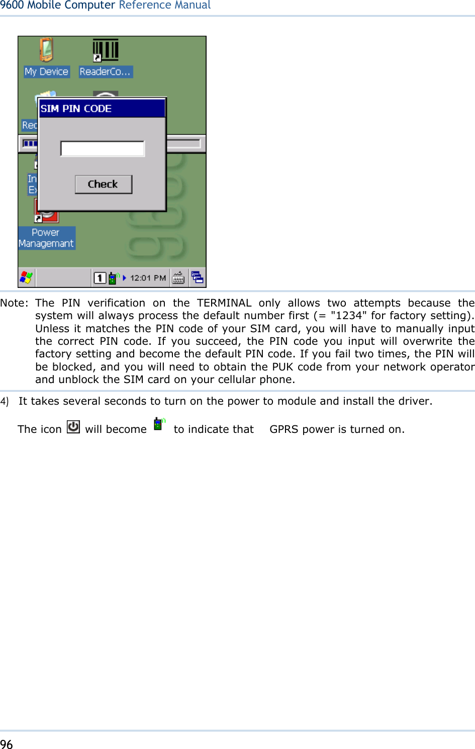
![97 Chapter 6 Using Reader Configuration Utility 6.2 GPRS CONNECTION 6.2.1 CONNECTING TO GPRS MODEM 1) Go to Start | Settings | Network and Dial-up Connections. 2) Tap and hold "GPRS" to select [Connect] from the pop-up menu. 3) If your dial-up configuration is correct, tap the [Connect] button in the Dial-Up Connection dialog box. Refer to 6.2.2 Configuring Dialing Properties. Note: You must connect to the GPRS modem specified by the mobile phone operator. 4) After you tap the [Connect] button, the GPRS status will go through opening port, user authenticated, device connected until it is connected finally. The status icon will appear on the taskbar to indicate the GPRS connection has been established successfully. If you want to disconnect, double-tap the icon and tap the [Disconnect] button.](https://usermanual.wiki/CipherLab/9600/User-Guide-1186622-Page-105.png)
![98 9600 Mobile ComputerReference Manual 6.2.2 CONFIGURING DIALING PROPERTIES If you need to configure the dial-up settings, tap the [Dial Properties] button in the Dial-Up Connection dialog box. Note: Alternatively, you may go to Start | Settings | Control Panel and select Dialing.](https://usermanual.wiki/CipherLab/9600/User-Guide-1186622-Page-106.png)
![99 Chapter 6 Using Reader Configuration Utility 6.2.3 CONFIGURING GPRS PROPERTIES 1) Go to Start | Settings | Network and Dial-up Connections. 2) Tap and hold "GPRS" to select [Properties] from the pop-up menu. 3) As long as SIM card is present, the default GPRS modem will appear as shown below. Tap [Configure].](https://usermanual.wiki/CipherLab/9600/User-Guide-1186622-Page-107.png)
![100 9600 Mobile ComputerReference Manual 4) Select the Call Options tab. The special modem commands inserted into the dial string must be [+CGDCONT=1,,"AP name"]. For example, change "INTERNET" below to the name of your GPRS AP.](https://usermanual.wiki/CipherLab/9600/User-Guide-1186622-Page-108.png)
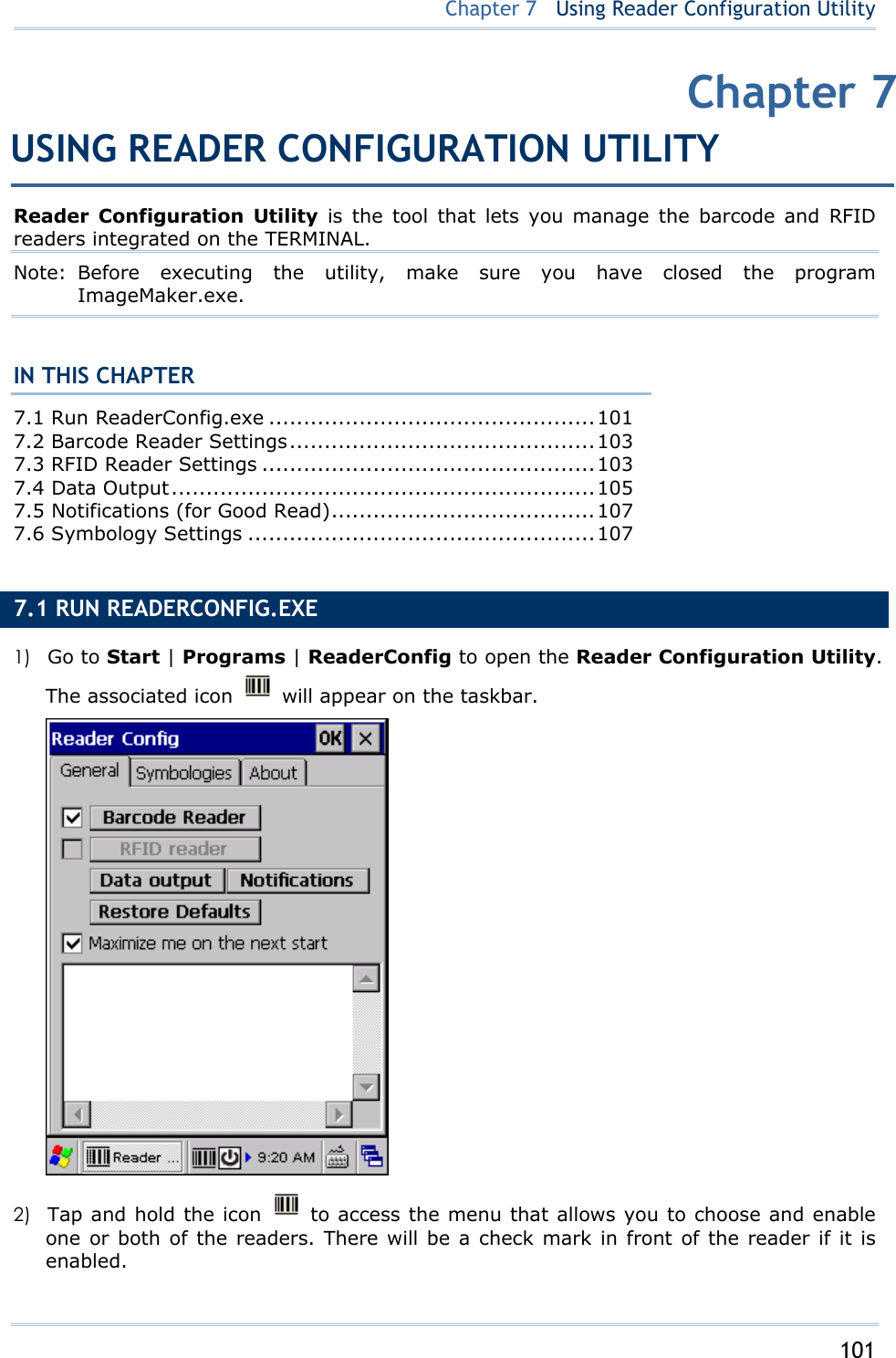
![102 9600 Mobile ComputerReference Manual If the RFID Reader is installed, the option will be available. 3) To meet your application requirements, proceed to configure associated reader settings as well as barcode settings. Note: (1) The ReaderConfig.exe utility will automatically detect the reader module(s) that is currently installed in the TERMINAL. (2) If you wish to reload the default settings, delete the ReaderCfgINI.txt file in DiskOnChip or tap [Restore Defaults] on the General tab.](https://usermanual.wiki/CipherLab/9600/User-Guide-1186622-Page-110.png)
![103 Chapter 7 Using Reader Configuration Utility 7.2 BARCODE READER SETTINGS The barcode reader configurations depend on the scan engine(s) installed. You can tell which reader is currently in use and make necessary changes on the General tab. Barcode Reader Description CCD/Laser Reader If installed, tap the [Barcode Reader] button to configure the reader settings for CCD or Laser scan engine. Refer to the Reader Settings Table in Appendix II - 錯誤! 找不到參照來源。.2D Reader The 2D scan engine is capable of reading linear and 2D barcodes. If installed, tap the [Barcode Reader] button to configure the reader settings for 2D scan engine. Refer to the Reader Settings Table in Appendix III - 錯誤! 找不到參照來源。. 7.3 RFID READER SETTINGS If the RFID scan engine is present, configurable options will be displayed. Note: Because it is possible to read barcode and RFID tag at the same time, it is recommended that only one scan engine is enabled at a time to prevent from misreading.](https://usermanual.wiki/CipherLab/9600/User-Guide-1186622-Page-111.png)
![104 9600 Mobile ComputerReference Manual Some RFID tags support both read/write operations, on a page-by-page basis. You may find it necessary to define your own read/write operation. For reference only, the table below lists the start page for read/write operation on a number of RFID tags. Start Page Tag Type Standard -1 Start from byte 0 of the default page (see below) for all tags 3 Mifare Ultralight ISO 14443A 4 SR176 ISO 14443B 3 ICODE SLI ISO 15693 0 LRI512 ISO 15693 3 SRF55VxxP ISO 15693 0 EM4135 ISO 15693 0 Tag-it HF-I ISO 15693 0 Others ISO 15693 5 ICODE ICODE® (Phillips) 0 Tag-it Tag-it® (TI) Note: Please refer to the specifications of your RFID tags for memory organization. 7.3.1 READ OPERATION By default, the RFID tag is read from byte 0 of the default page. However, the default page, amount of bytes and number of pages of each tag may be different. Specify how many bytes of data you want to read from the tag. Generally, the read data is user data obtained from the user block. If you are sure that the data is to be read from a non-user block, such as the lock block, you need to select the check box of [Display hex values] first. 7.3.2 WRITE OPERATION Type the string that you want to write to a tag. By default, the string is written to the tag from byte 0 of the default page. However, the default page, amount of bytes and number of pages of each tag may be different. Therefore, the input string will automatically be truncated to fit into pages, and data may be discarded when it comes to the end of pages available. Generally, it will write the input string to the user block, which is free for custom use. The string will be displayed as “user data”. If you wish to write the string to a non-user block, such as the lock block, you need to select the check box of [Use hex values] first. Once you have selected to use hex values for the string, the string length must be even. For example, if you want to write 0x0A, 0x0B and 0x00 to a tag, the string you input must be “0A0B00” instead of “AB0”.](https://usermanual.wiki/CipherLab/9600/User-Guide-1186622-Page-112.png)
![105 Chapter 7 Using Reader Configuration Utility 7.4 DATA OUTPUT Tap the [Data Output] button on the General tab to choose from the three options for data output after decoding as well as configure associated settings. Data Output Default Keyboard Emulation Data is emulated as typed text and sent to the active Window. When “Local machine” is selected, simply run your application or built-in program, such as WordPad, to start with data collection. When “RDP server” is selected, run the Remote Desktop Connection program to connect to a remote computer. Note that this option is unable to emulate double bytes, such as Big-5 or Unicode characters on the remote PC. Local machine](https://usermanual.wiki/CipherLab/9600/User-Guide-1186622-Page-113.png)
![106 9600 Mobile ComputerReference Manual Windows Message When selected, a Windows message will be broadcasted after decoding. Intercept the decode message in your application. Call Windows API (ReadMsgQueue) in your application to retrieve the decoded data. Disable Windows Event When selected, a Windows event will be broadcasted after decoding. Disable Intercept the decode event in your application. Call Windows API (ReadMsgQueue) in your application to retrieve the decoded data. Note: (1) Refer to CipherLab WinCE Products Programming Guide for details on Windows Message and Windows Event. Sample programs are provided by request. (2) For the use of a different program rather than ReaderConfig.exe, a dynamic-link library (DLL) file is provided. Auto ENTER This function can spare you the trouble of pressing the [Enter] key on the TERMINAL to confirm each scan. It will automatically add an ENTER character in front or to the end of one scan. No Scan + ENTER ENTER + Scan Scan + ENTERAuto ENTER Character *Auto ENTER must be enabled. None Carriage Return Tab Space Comma Semicolon Carriage Return Prefix String 0~10 characters NULL Suffix String 0~10 characters NULL Display Code Type Select the check box to prefix the code type to barcode data after decoding a barcode. Disabled Display Code Length Select the check box to suffix the code length to barcode data after decoding a barcode. Disabled Display RFID UID Select the check box to display UID after decoding an RFID tag. Enabled Display RFID User Data Select the check box to display user data after decoding an RFID tag. Disabled Field Delimiter Decide whether or not to use a delimiter to separate data fields after decoding a barcode or an RFID tag — Code type, barcode data, and code length if more than one field is displayed UID and user data if both are displayed ‘ , ’ (comma)](https://usermanual.wiki/CipherLab/9600/User-Guide-1186622-Page-114.png)
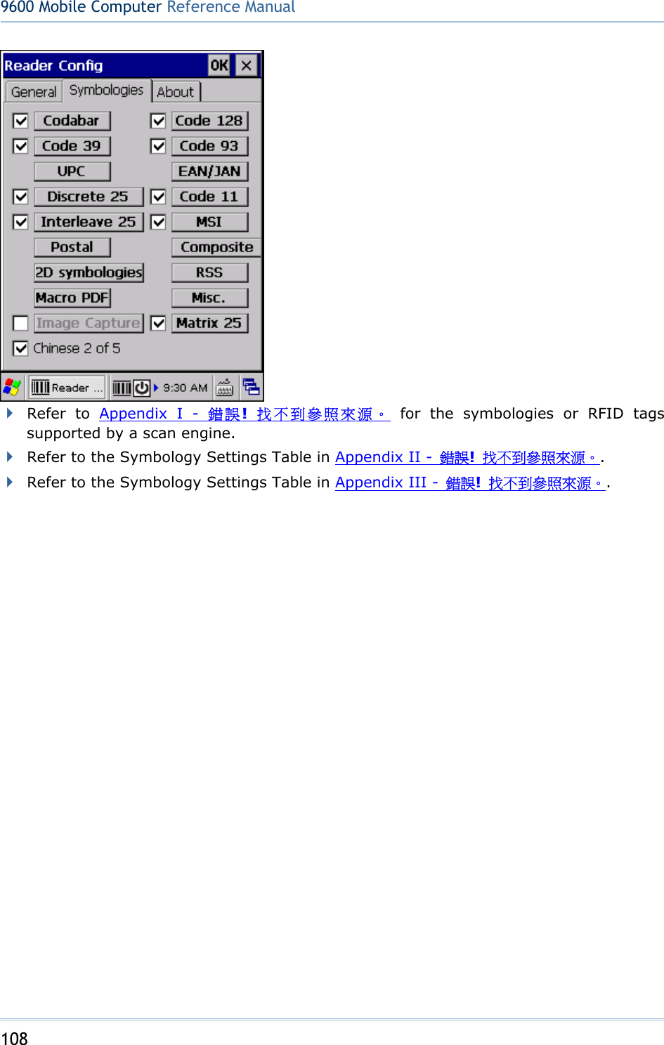
![107 Chapter 7 Using Reader Configuration Utility 7.5 NOTIFICATIONS (FOR GOOD READ) Tap the [Notifications] button on the General tab to configure how you want to be notified of a successful decoding. Sound / Vibration Default Good Read via speaker Mute, or Sound 1~9 Sound 1 Good Read via buzzer Specify frequency and duration Duration 0~255 (0.1 sec.); 0 = Disable the buzzer 0 (= Disable) Good Read via vibrator 0~30 (sec.) 0 = Disable the vibrator 0 (= Disable) Good Read LED Select the check box to enable Good Read LED. The LED will become green to indicate a successful decoding. Disable 7.6 SYMBOLOGY SETTINGS For barcode settings, tap the Symbologies tab.](https://usermanual.wiki/CipherLab/9600/User-Guide-1186622-Page-115.png)