CipherLab M0010A Terminal User Manual 9400 Mobile Computer v1 00
CipherLab Co., Ltd. Terminal 9400 Mobile Computer v1 00
UserManual.wiki
>
CipherLab
>
M0010A User Manual
user manual
Navigation menu
Upload a User Manual
Namespaces
Wiki Guide
HTML
PDF
Info
Views
User Manual
Discussion / Help
Navigation
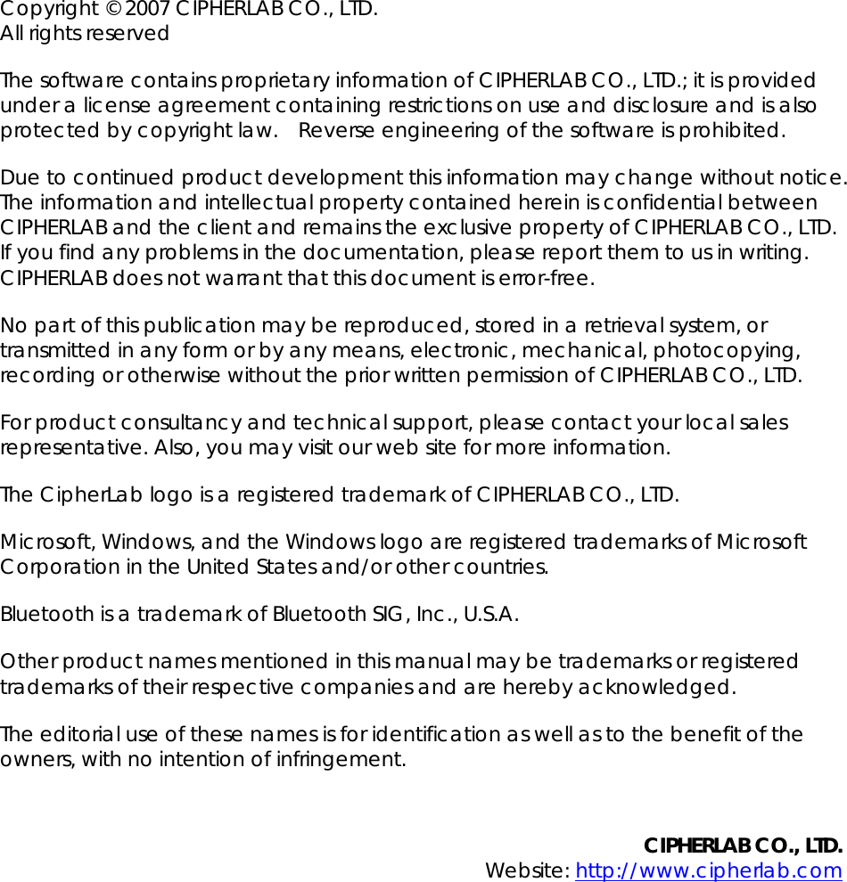

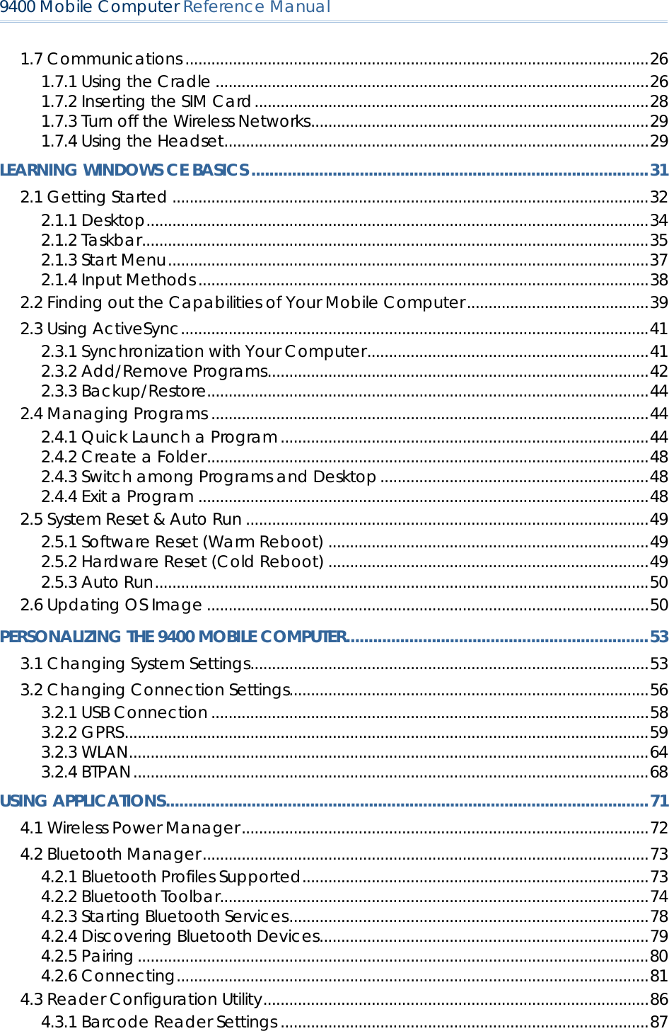
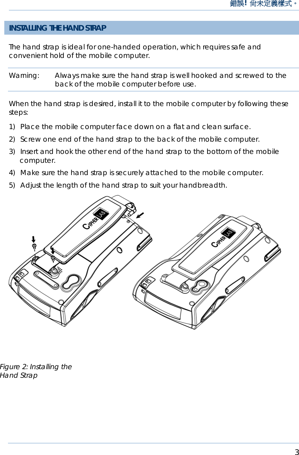
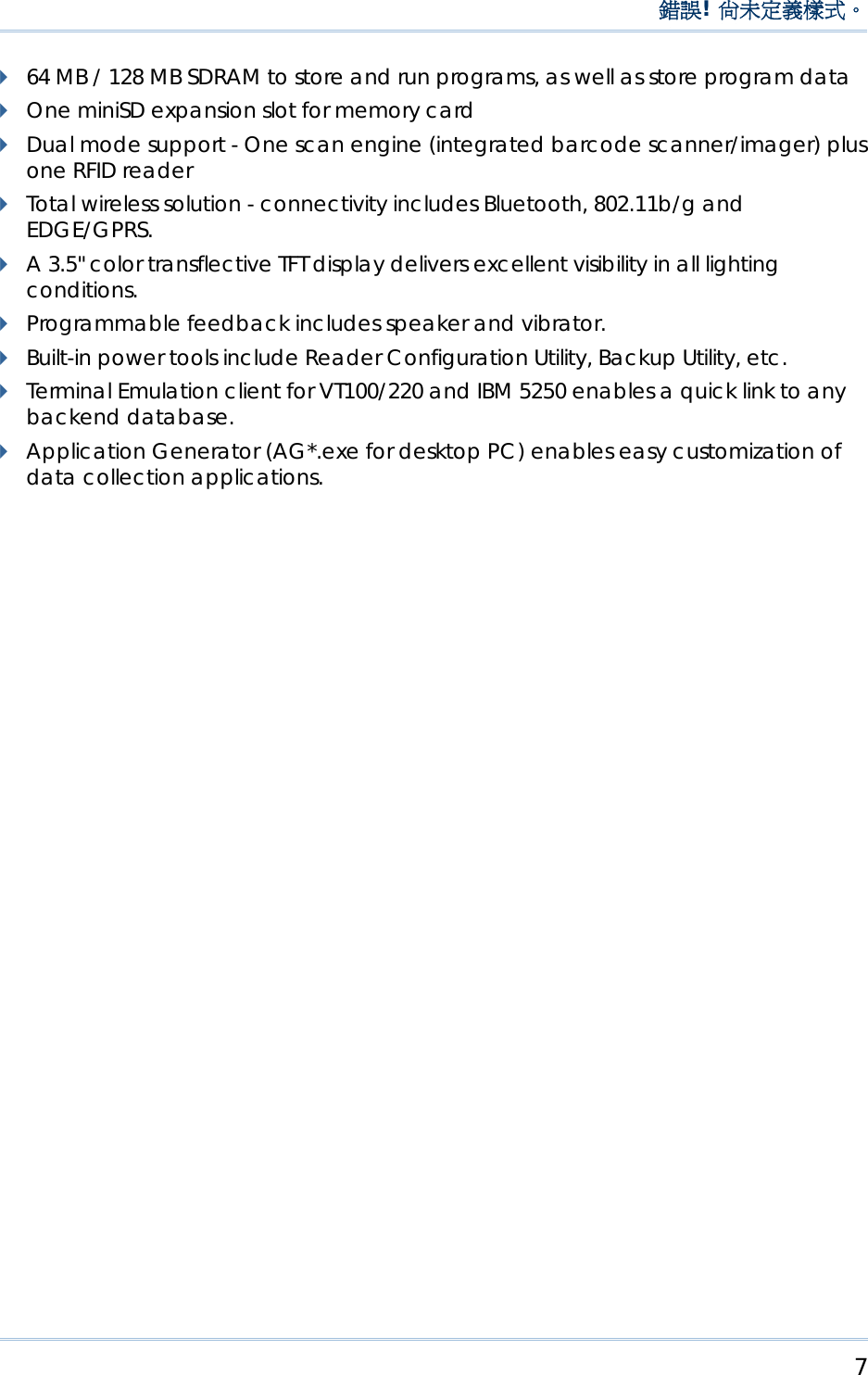
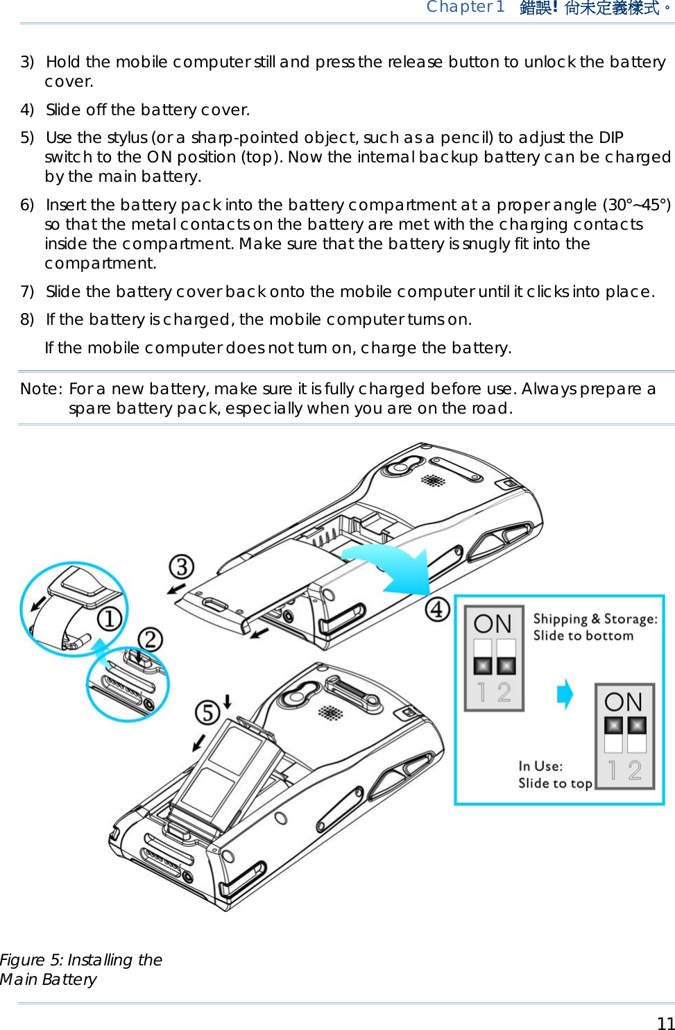
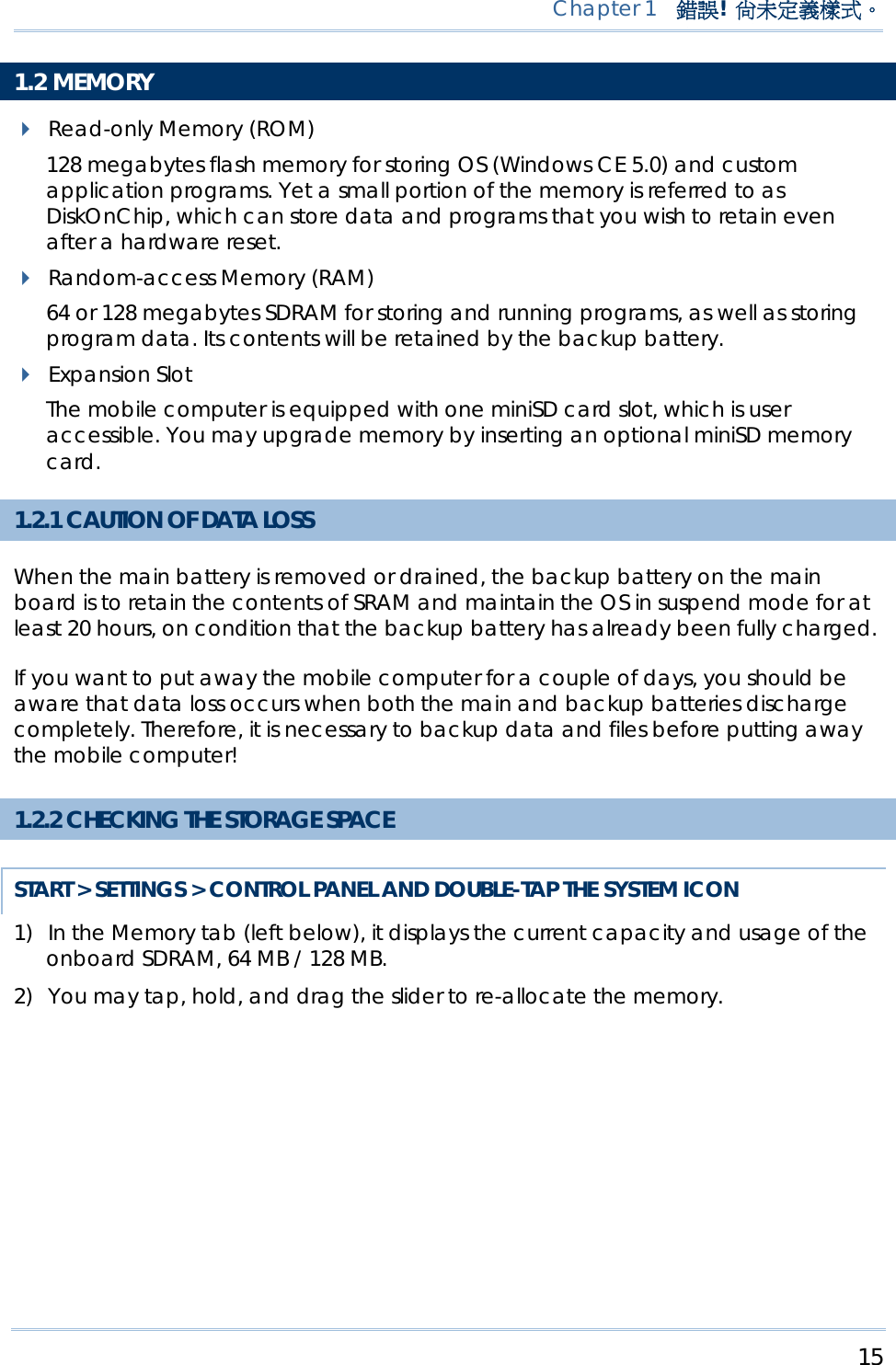
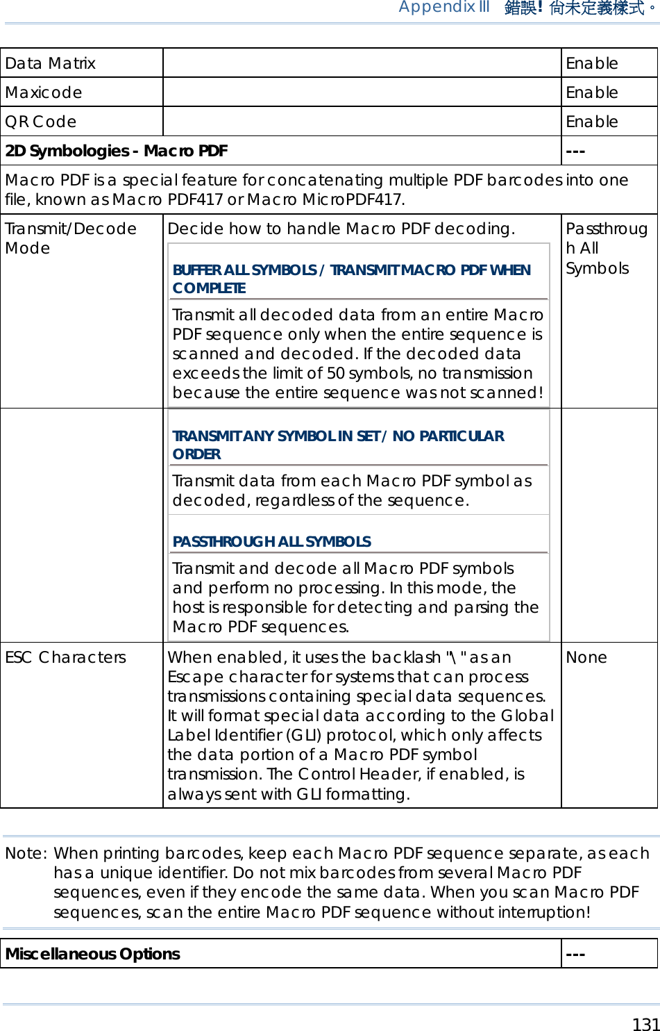
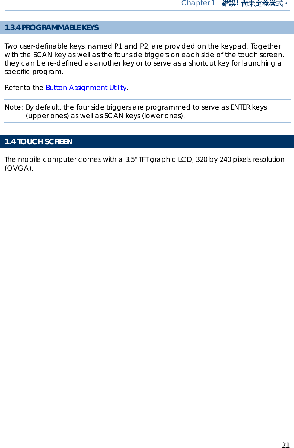
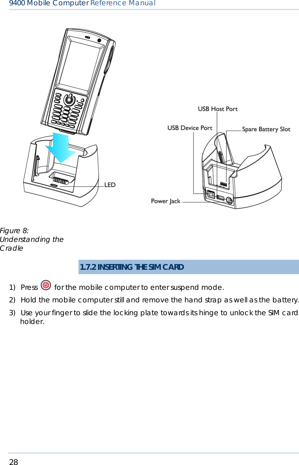
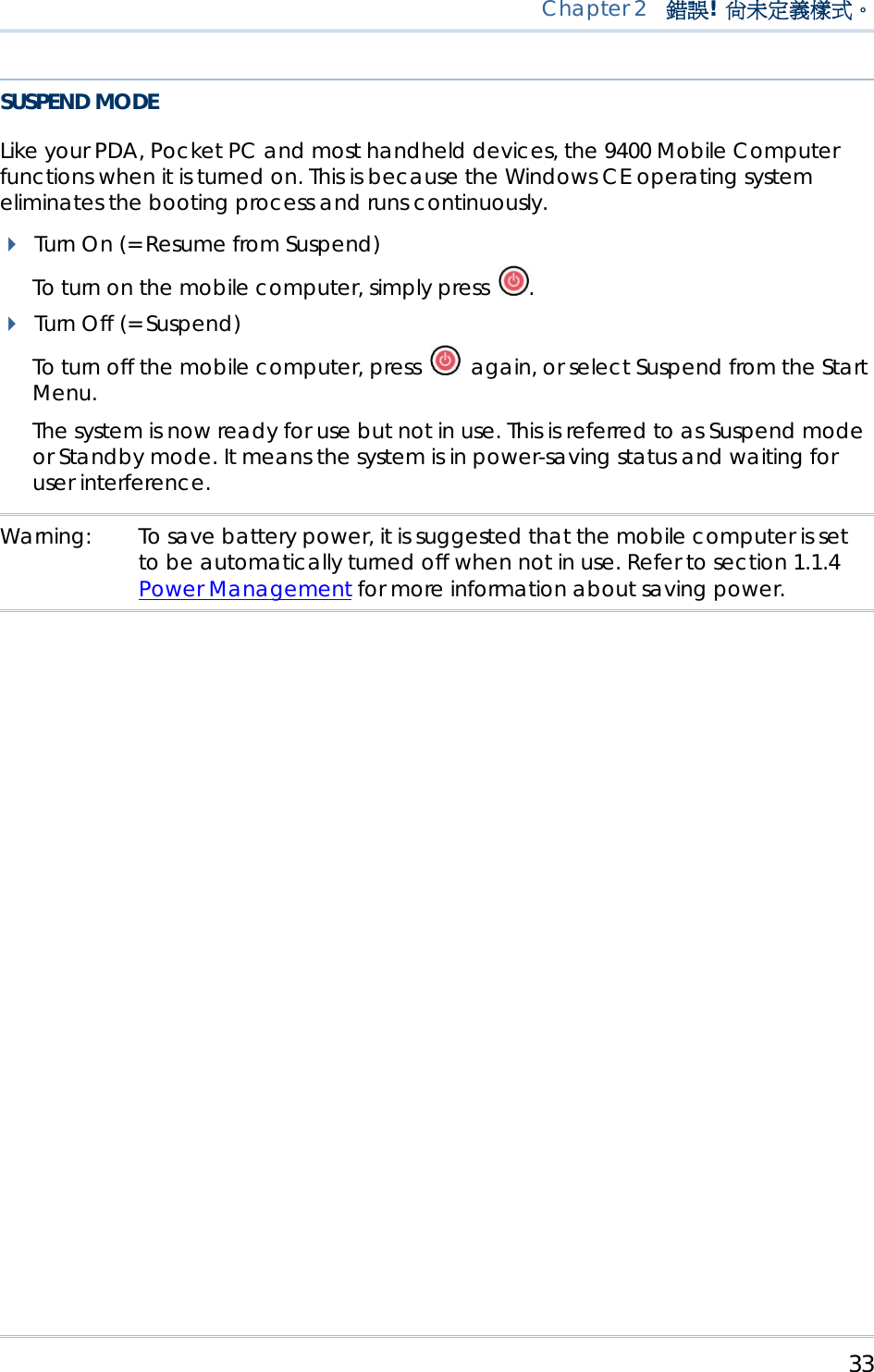
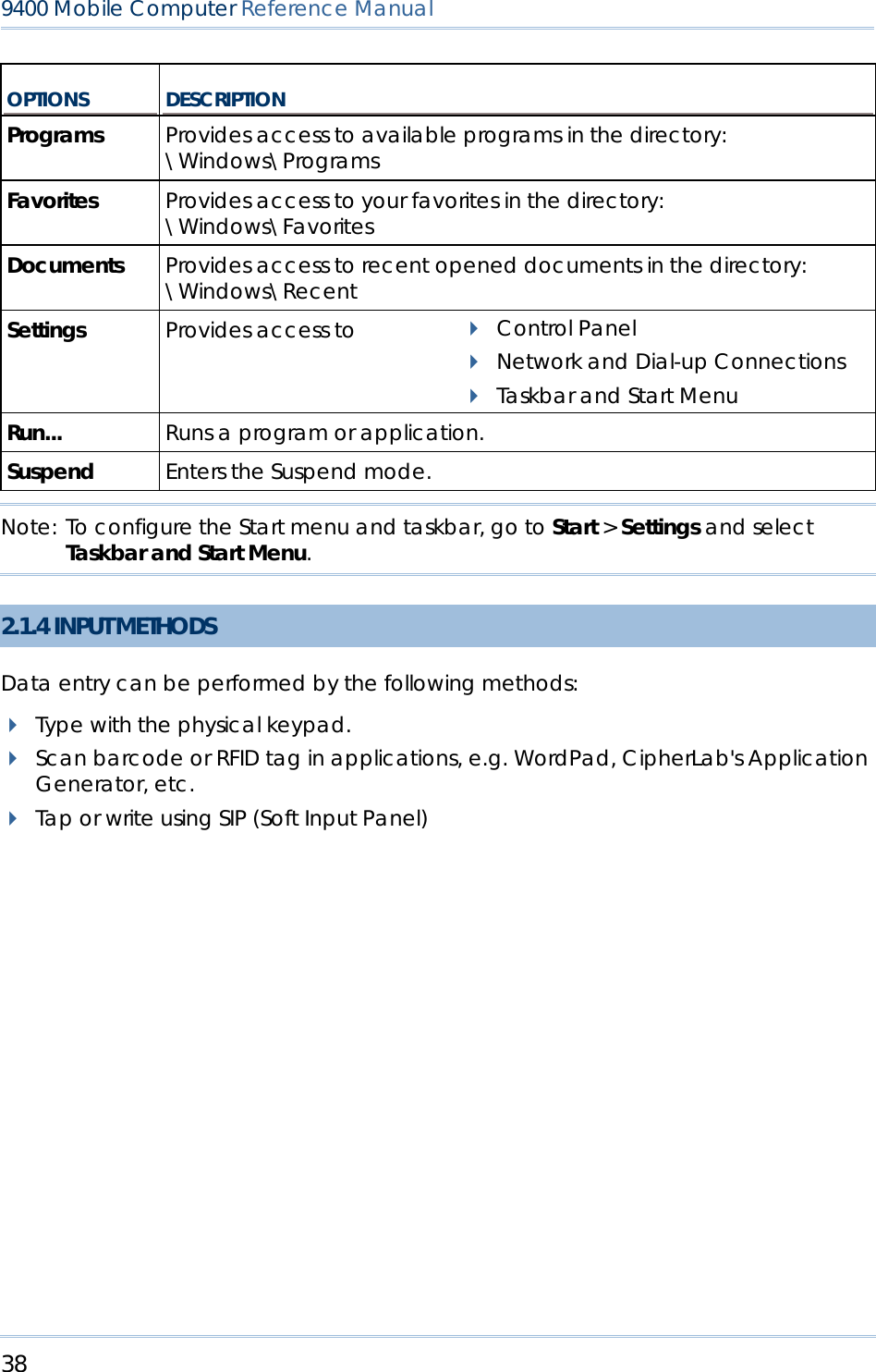
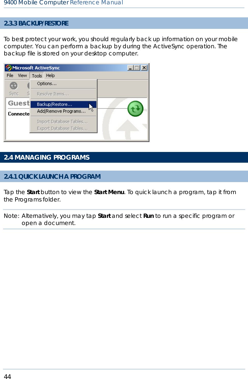
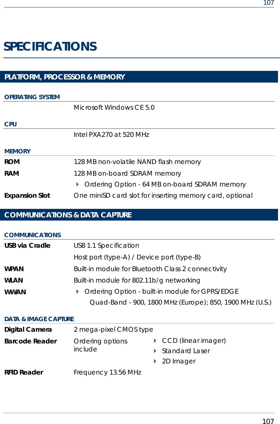
![19 Chapter 1 錯誤! 尚未定義樣式。 Note: Functionality of keys is application-dependent. 1.3.1 USING THE KEYPAD PRESS FIRST, AND THEN The LED backlight of keypad is turned off by default. It can be toggled ON/OFF by the key combination: [Func] + [0]. START > SETTINGS > CONTROL PANEL AND DOUBLE-TAP THE KEYBOARD ICON The Character Repeat functionality is enabled by default. You may cancel the check box to disable it. When enabled, tap, hold, and drag the slider for a desired Repeat Delay and Repeat Rate. Warning: It is suggested to turn on the keypad backlight while working in a dark area; however, using backlight while on battery power will substantially reduce battery life. 1.3.2 ALPHA KEY This alphanumeric keypad is set to numeric mode by default. The Alpha key serves as a toggle among numeric, alpha (lower-case alphabetic), and ALPHA (upper-case alphabetic) input modes. Note: It is not necessary to hold down the [Alpha] key. The alpha icon will appear on the status bar in a sequence as shown below. STATUS ICON ALPHA KEY INPUT MODE N/A Numbers Press one time Small letters Press two times Capital letters Note: If you are using the software keypad via SIP, tap CAP (Caps Lock) to toggle between upper case and lower case alphabetic modes. Figure 7: 28-key Layout](https://usermanual.wiki/CipherLab/M0010A/User-Guide-915892-Page-27.png)
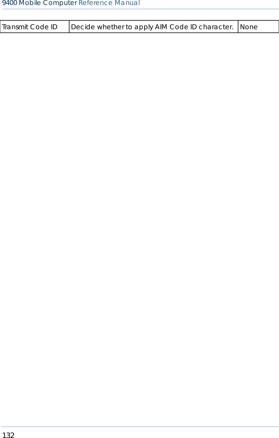
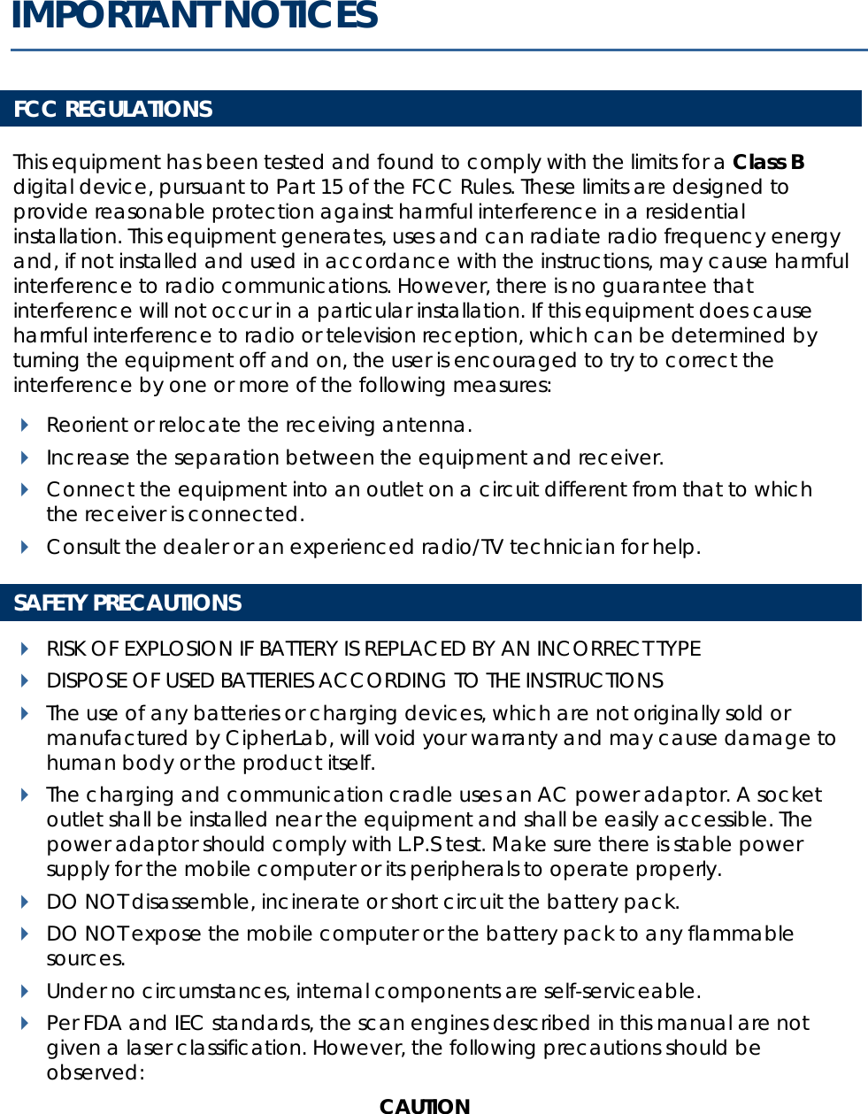
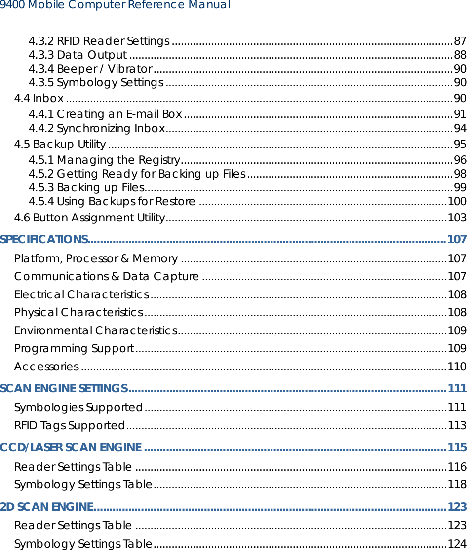
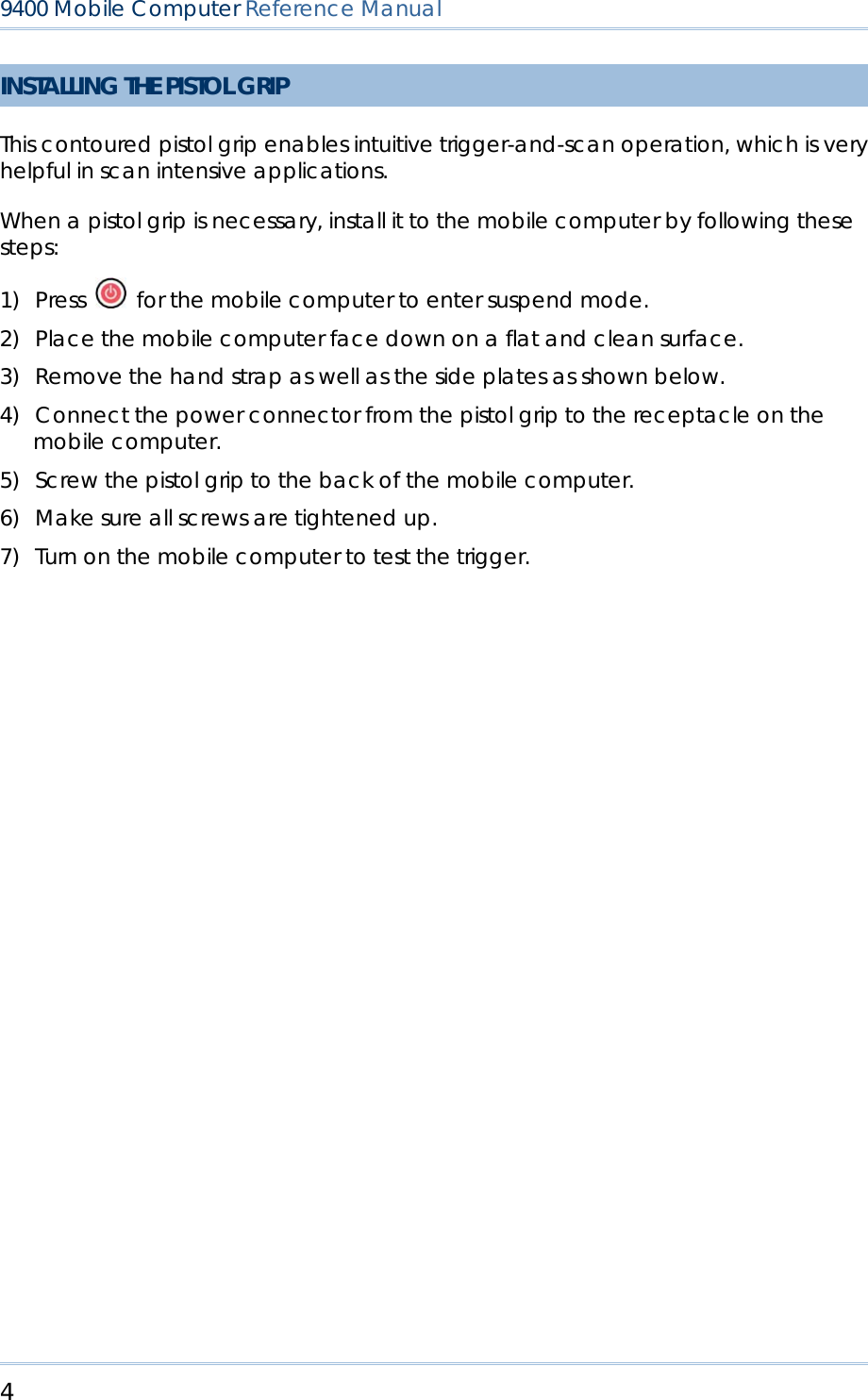
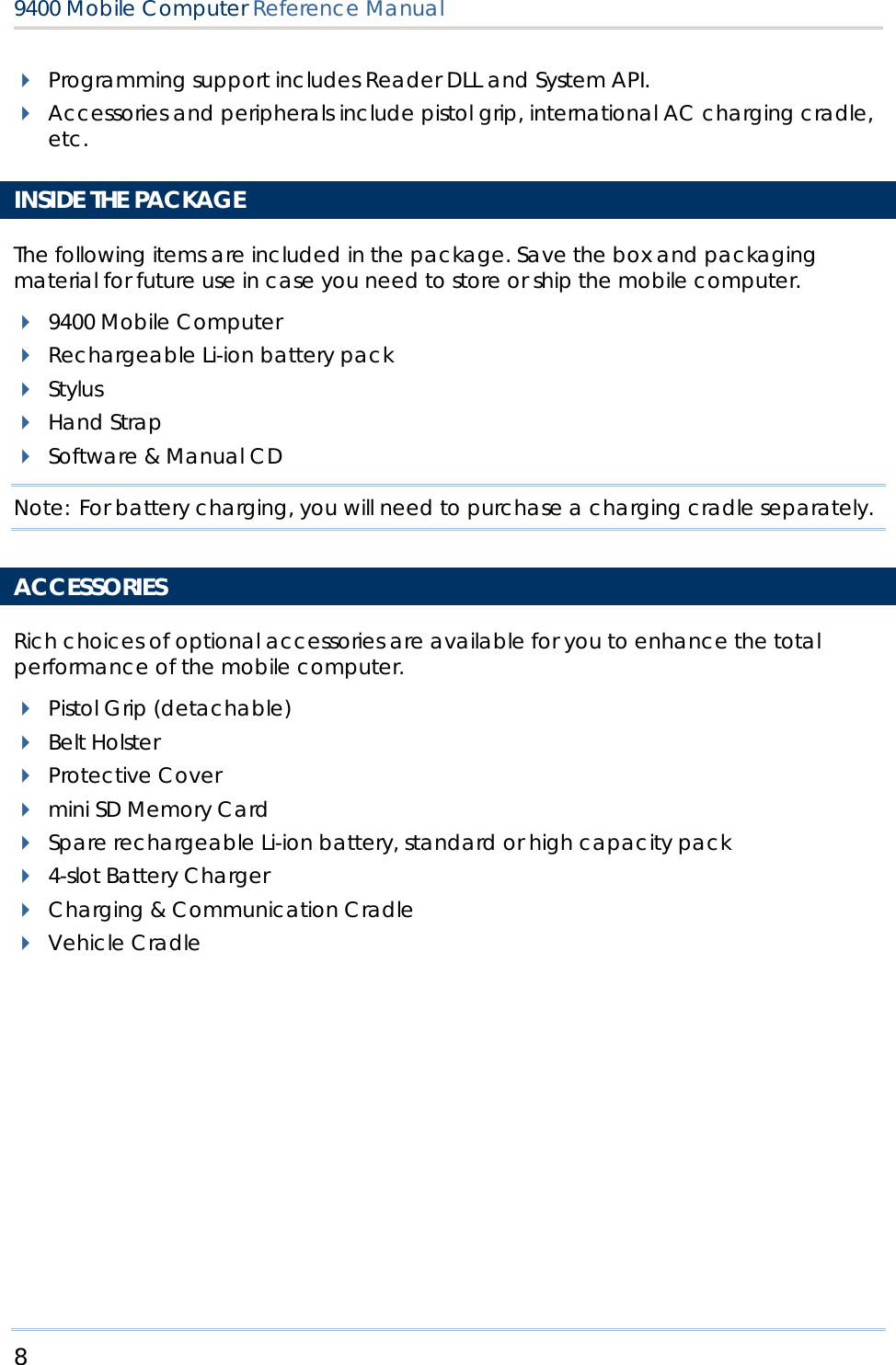
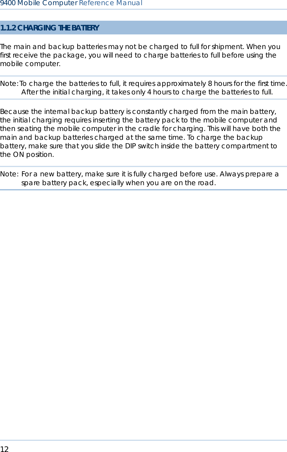
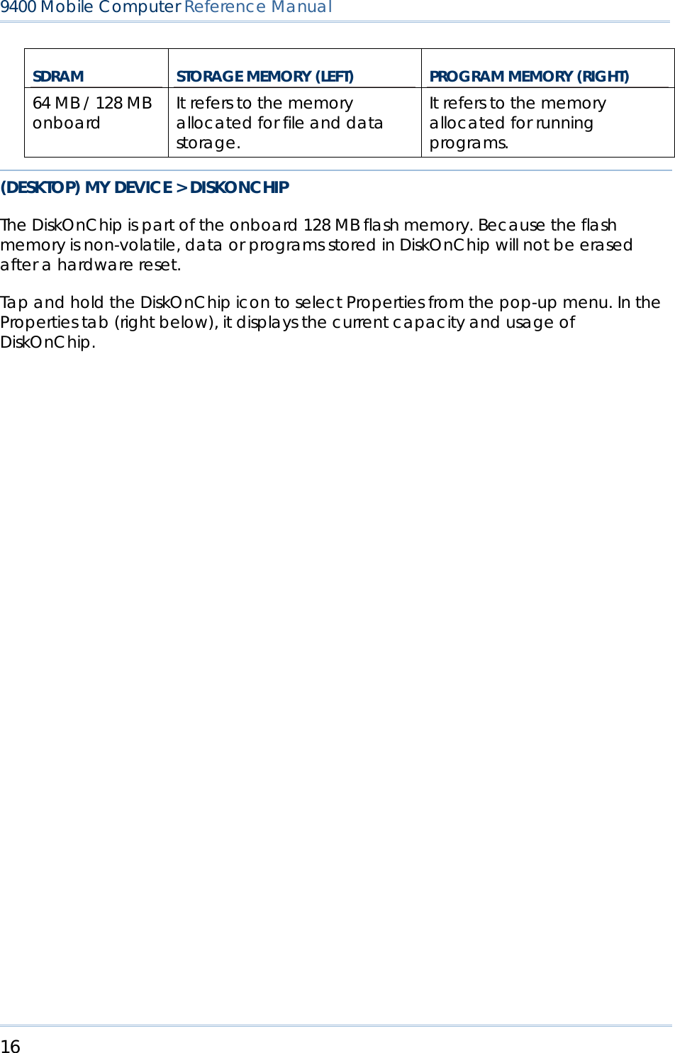
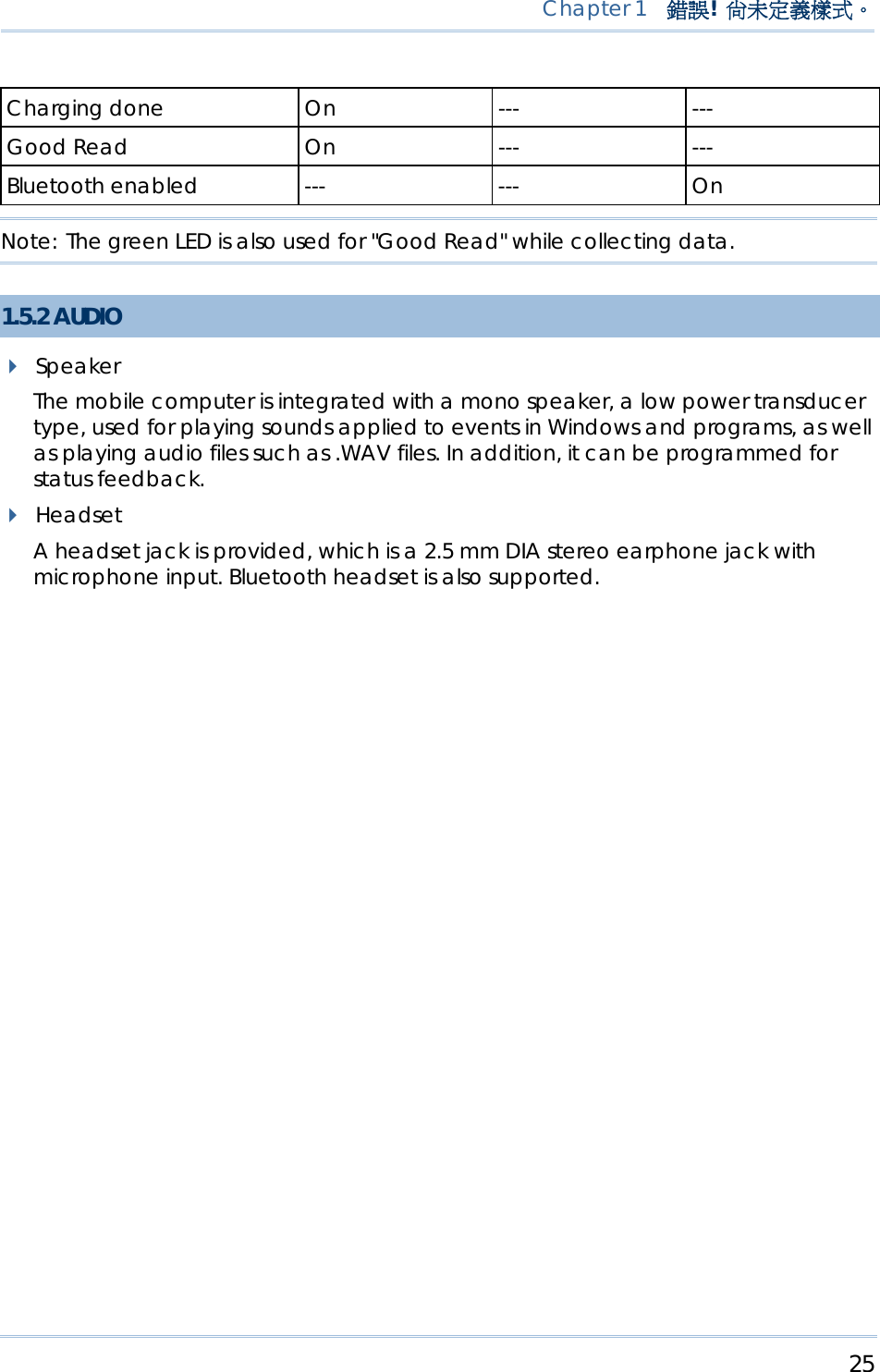
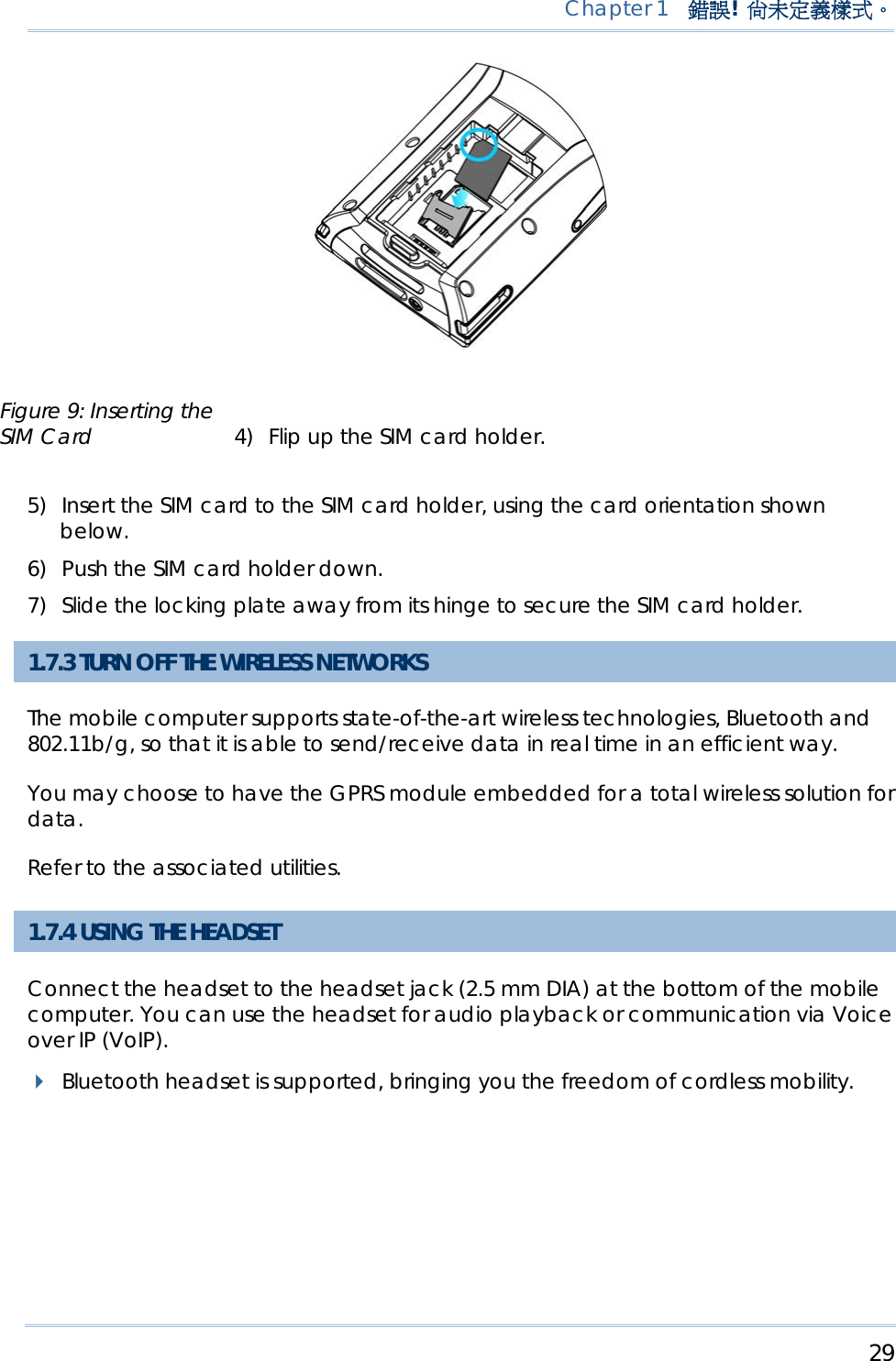
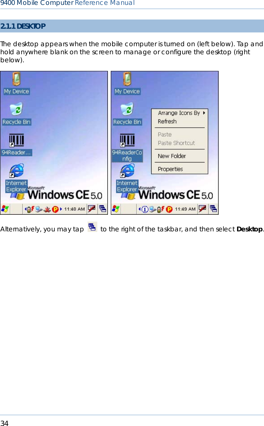
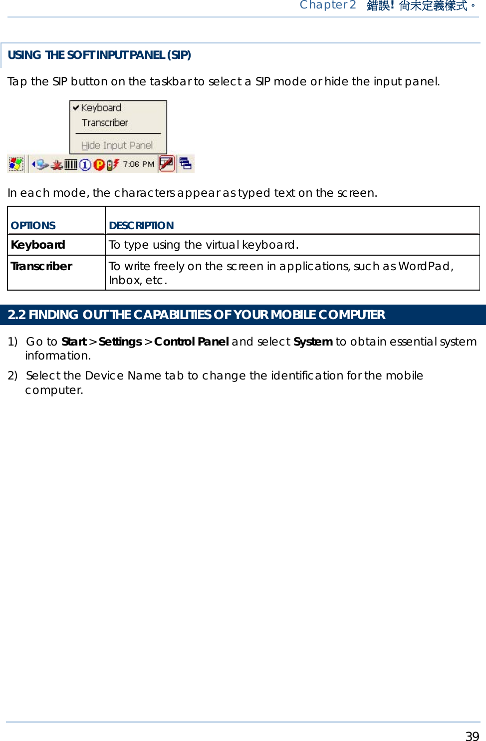
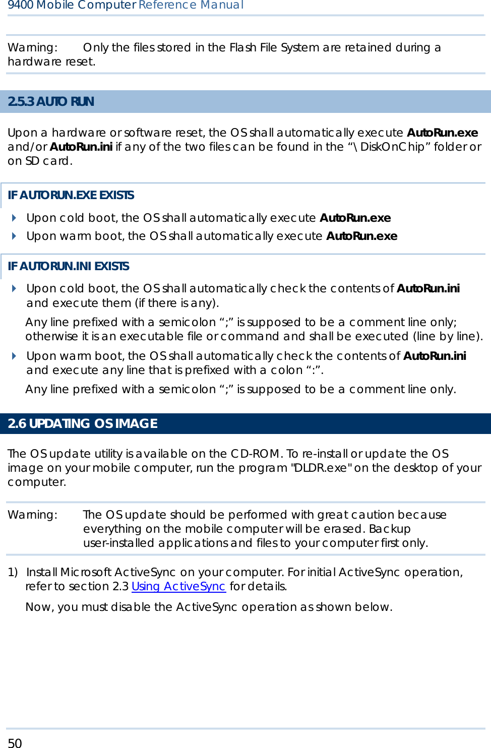
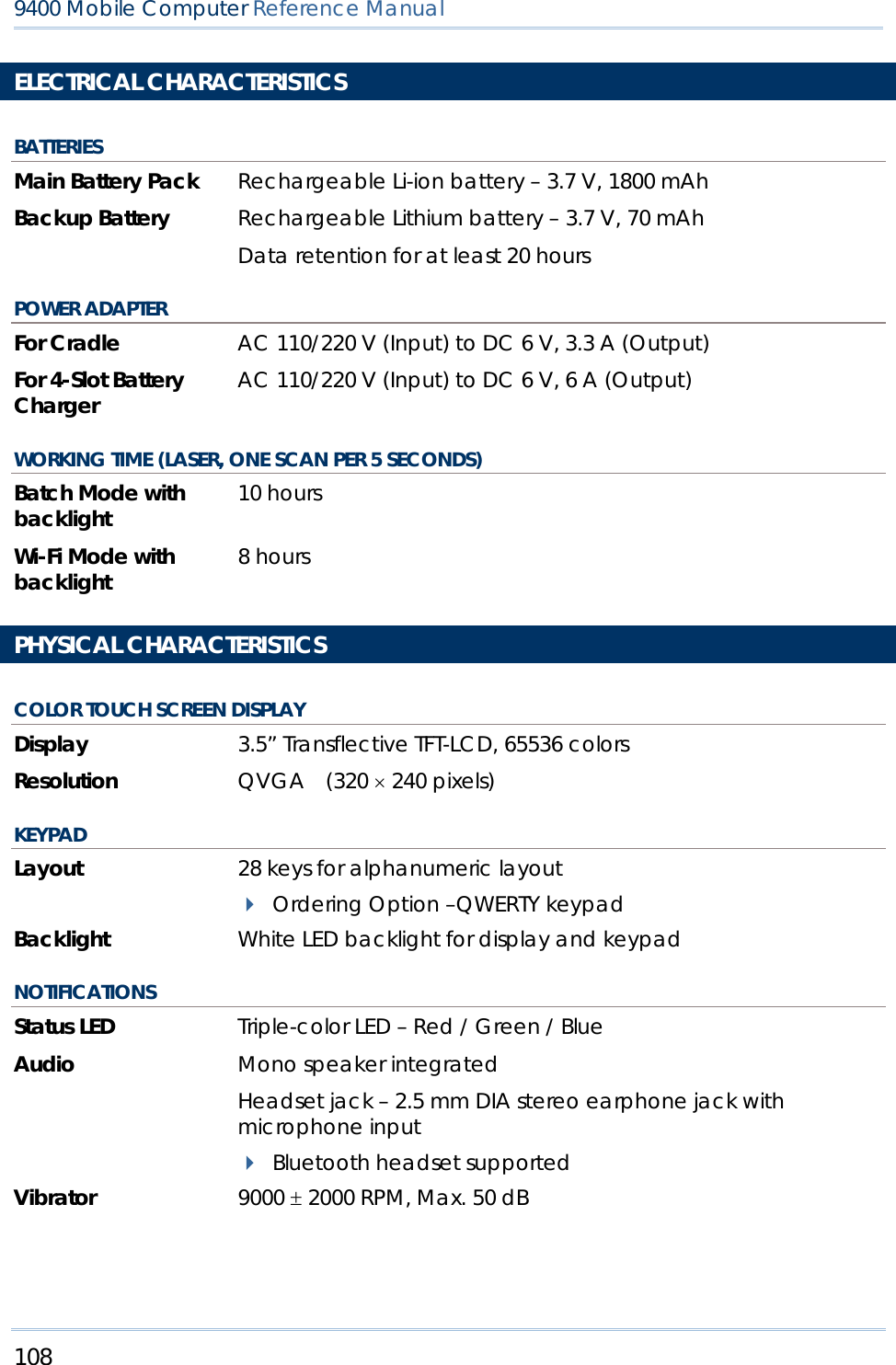
![20 9400 Mobile Computer Reference Manual 1.3.3 FUNCTION KEY The [Func] (function) key serves as a modifier key. 1) To enable this modifier key, press on the keypad. A circular icon of the letter "F" will appear on the status bar. This modifier key is hold down as long as the icon is displayed. 2) Now press another key to get the value of key combination (say, press [1] to get the value of F1). The icon will go off now. 3) To get the value of another key combination modified by the [Func] key, repeat the above steps. 4) To abort the key modification, press again, and the icon will go off. Note: It is not necessary to hold down the [Func] key. The functionality of each key combination is application-dependent. Below is a list of the factory setting for a variety of key combinations. KEY COMBINATION ACTION , PgUp (red-coded): move text up one screenful , PgDn (red-coded): move text down one screenful , Home (red-coded): move to the beginning of screen or document , End (red-coded): move to the end of screen or document , Toggle ON/OFF the backlight of keypad only , Turn ON the backlight of LCD and decrease its luminosity , Turn ON the backlight of LCD and increase its luminosity Note: Press the [Func] key first, and then press the second key for a specific function.](https://usermanual.wiki/CipherLab/M0010A/User-Guide-915892-Page-28.png)
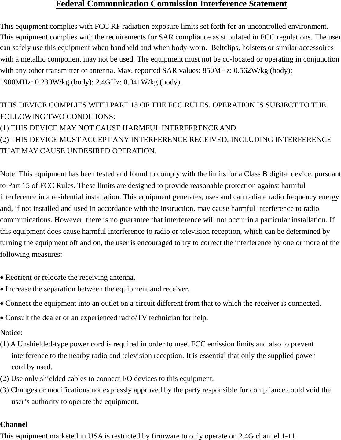
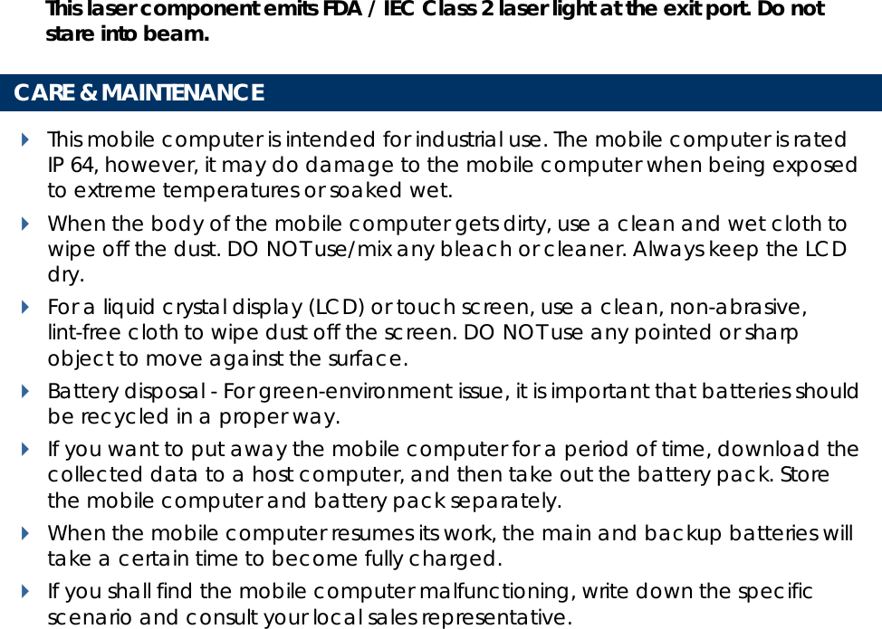
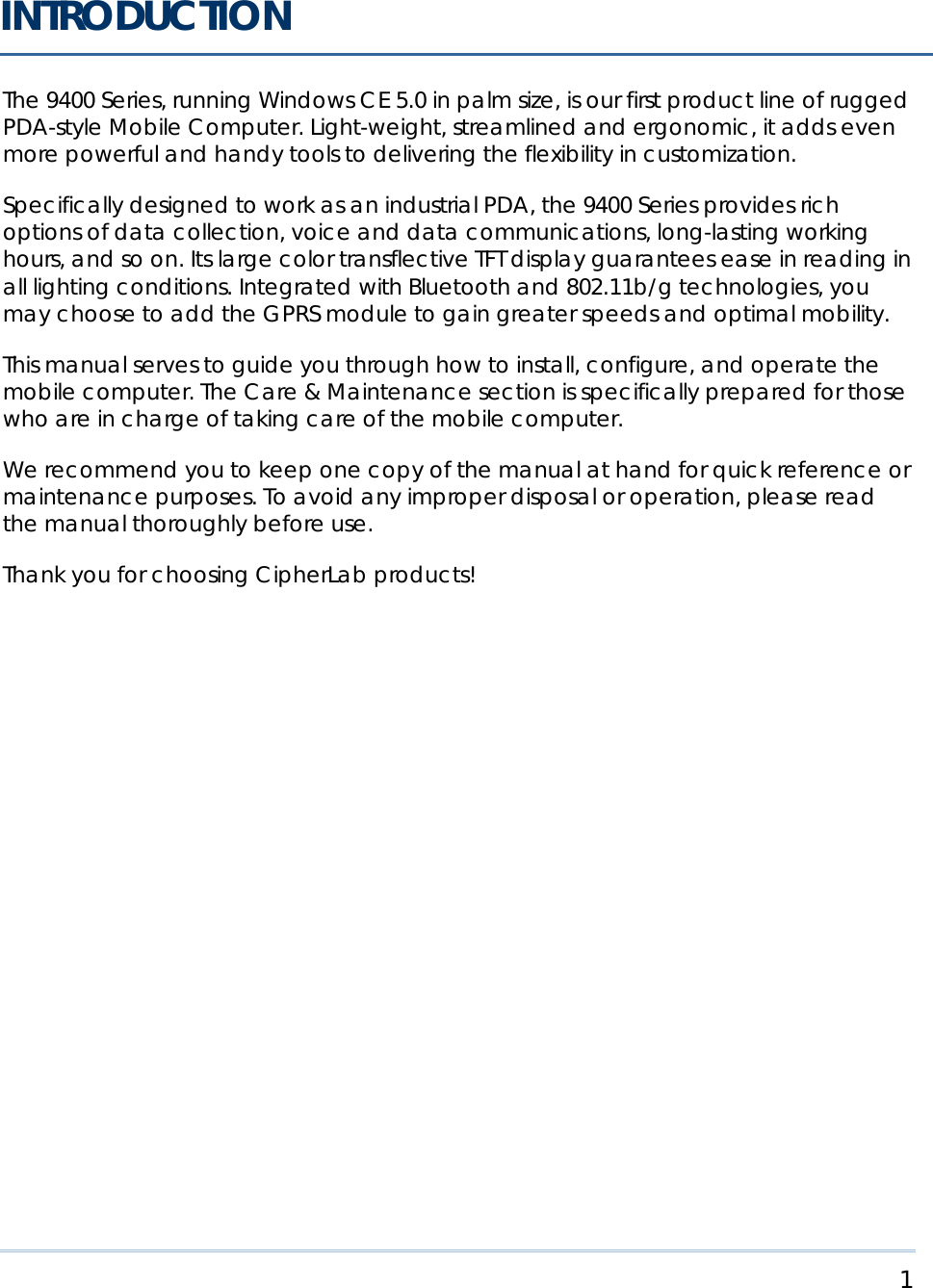
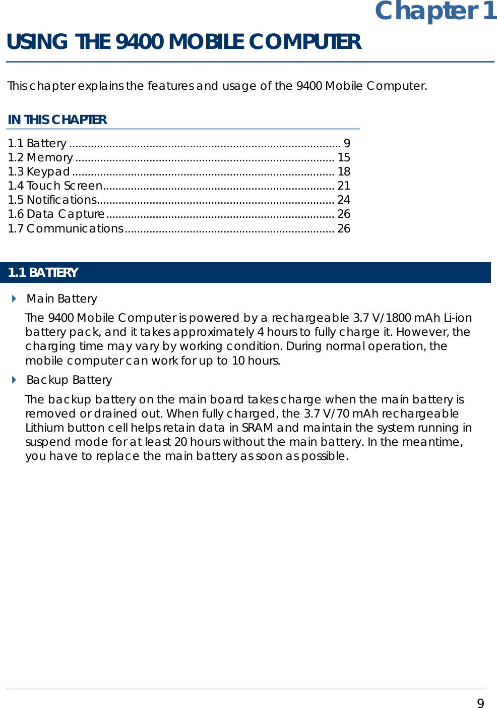
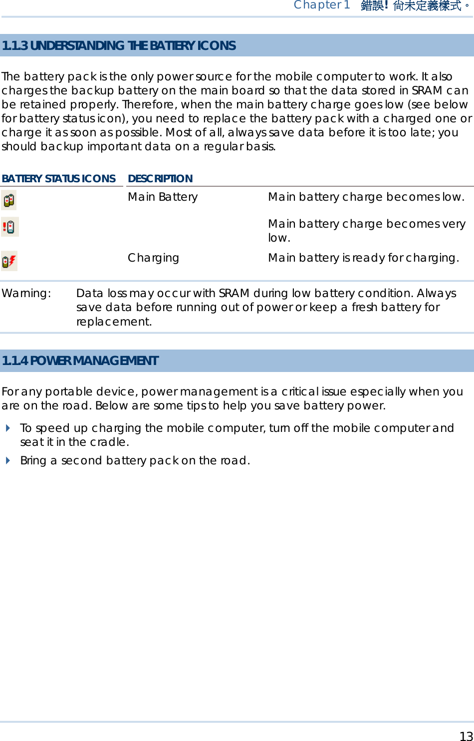
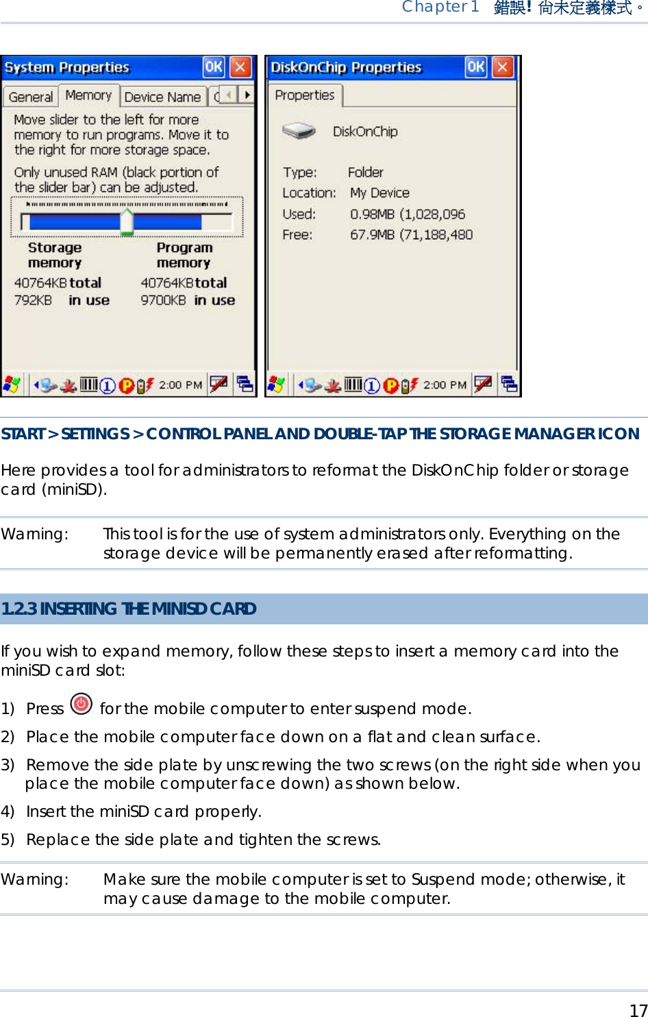
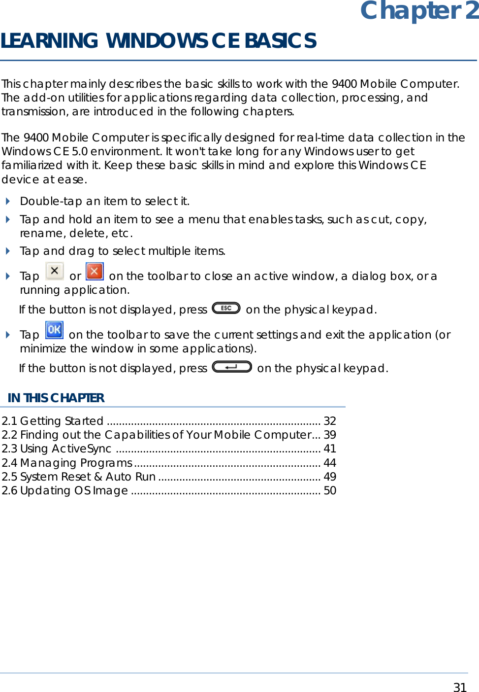
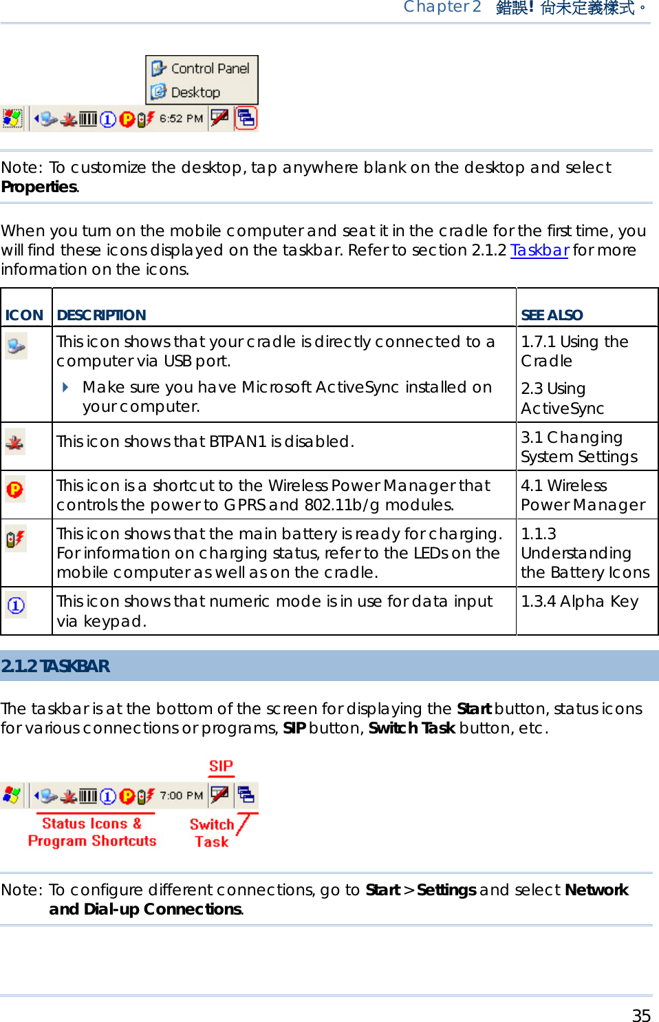
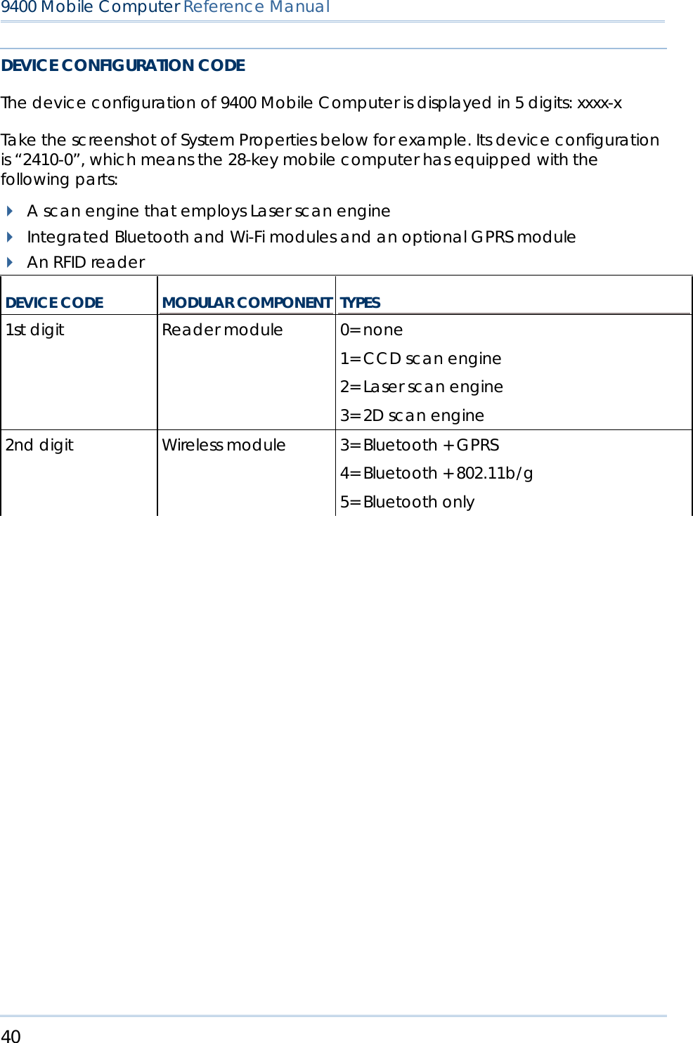
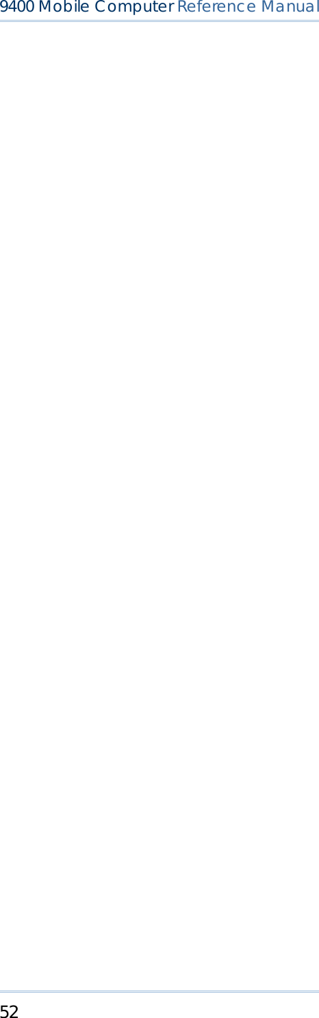
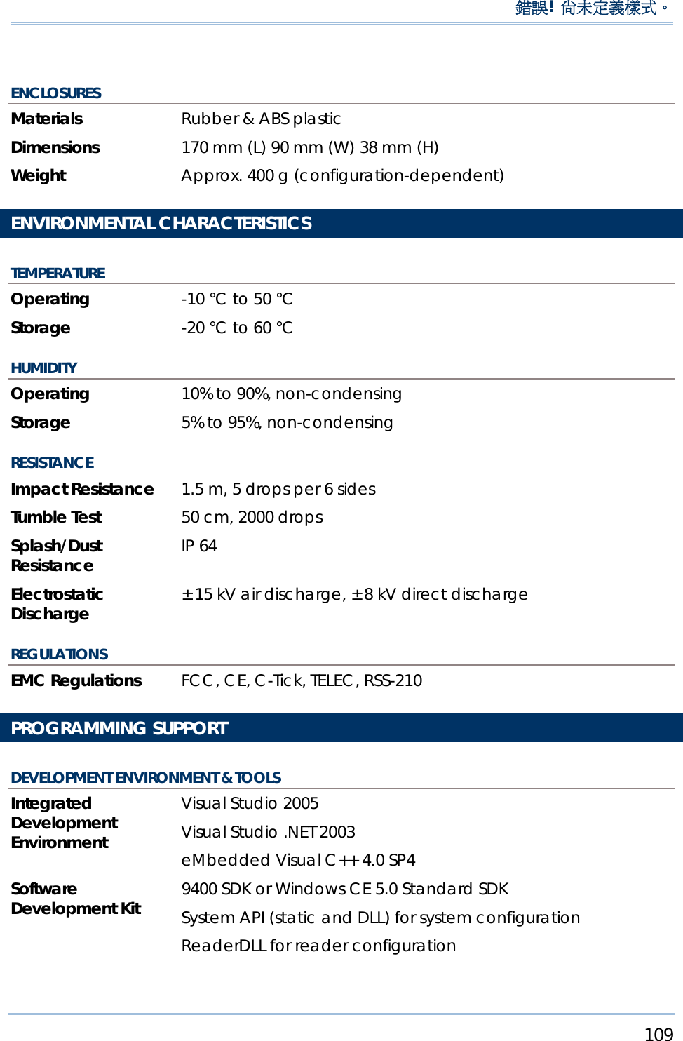
![22 9400 Mobile Computer Reference Manual The LED backlight of screen, which helps ease reading under dim environments, can be controlled manually and automatically. Warning: Using backlight while on battery power will substantially reduce battery life. It is suggested to dim the backlight while working in a well-lit area or automatically turn off the mobile computer when not in use. 1.4.1 ADJUSTING THE BACKLIGHT PRESS FIRST, AND THEN The LED backlight of the screen can be turned on and adjusted decreasingly by the key combination: [Func] + [-]. Keep pressing the key combination ([Func] first, and then [-]) until the luminosity is decreased to a desired level. PRESS FIRST, AND THEN The LED backlight of the screen can be turned on and adjusted increasingly by the key combination: [Func] + [.]. Keep pressing the key combination ([Func] first, and then [.]) until the luminosity is increased to a desired level. START > SETTINGS > CONTROL PANEL AND DOUBLE-TAP THE DISPLAY ICON 1) Tap the Backlight tab (left below). 2) Select one or both of the check boxes to automatically turn off the LCD backlight when using batteries or external power. From the appropriate list, select the amount of time the device should be idle before the backlight is turned off.](https://usermanual.wiki/CipherLab/M0010A/User-Guide-915892-Page-30.png)
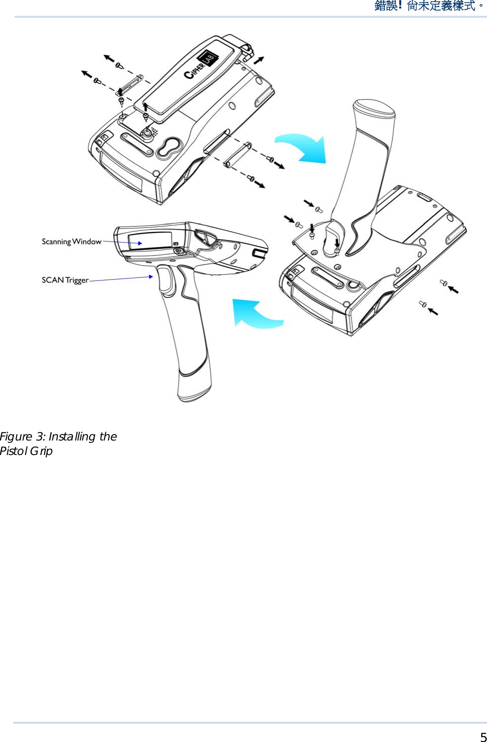
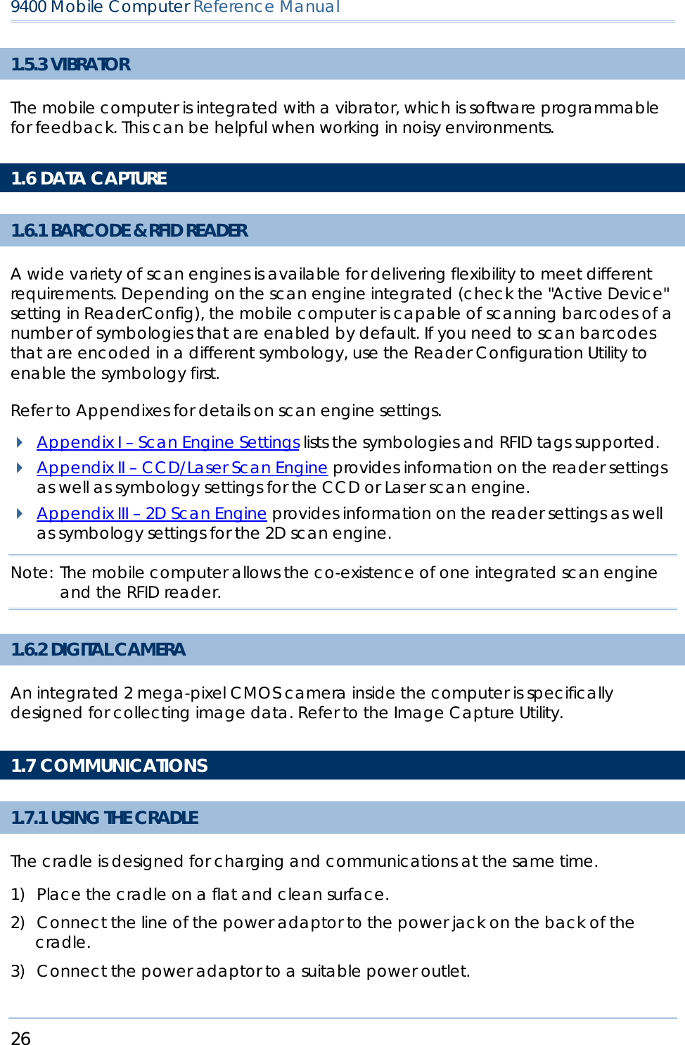
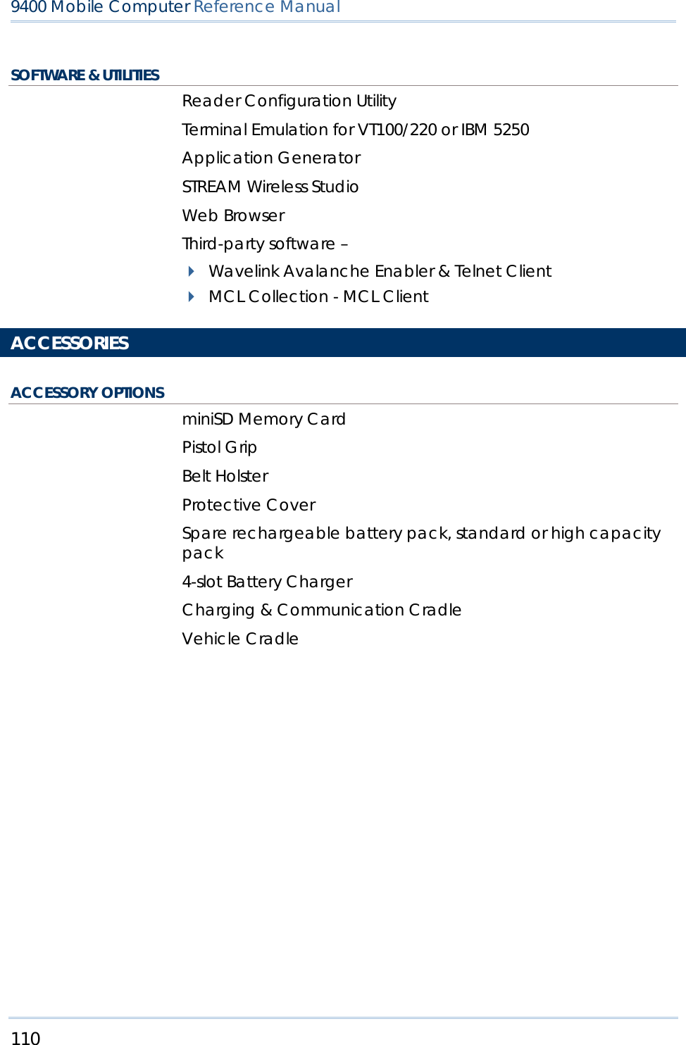
![23 Chapter 1 錯誤! 尚未定義樣式。 3) Tap the [Advanced] button (right above). 4) In the Settings tab, you can select the luminosity of backlight when it is set to be automatically turned on by pressing any key or tapping the screen. Tap, hold, and drag the slider for AC and battery powered respectively. For more luminosity, move the slider to the right.](https://usermanual.wiki/CipherLab/M0010A/User-Guide-915892-Page-31.png)
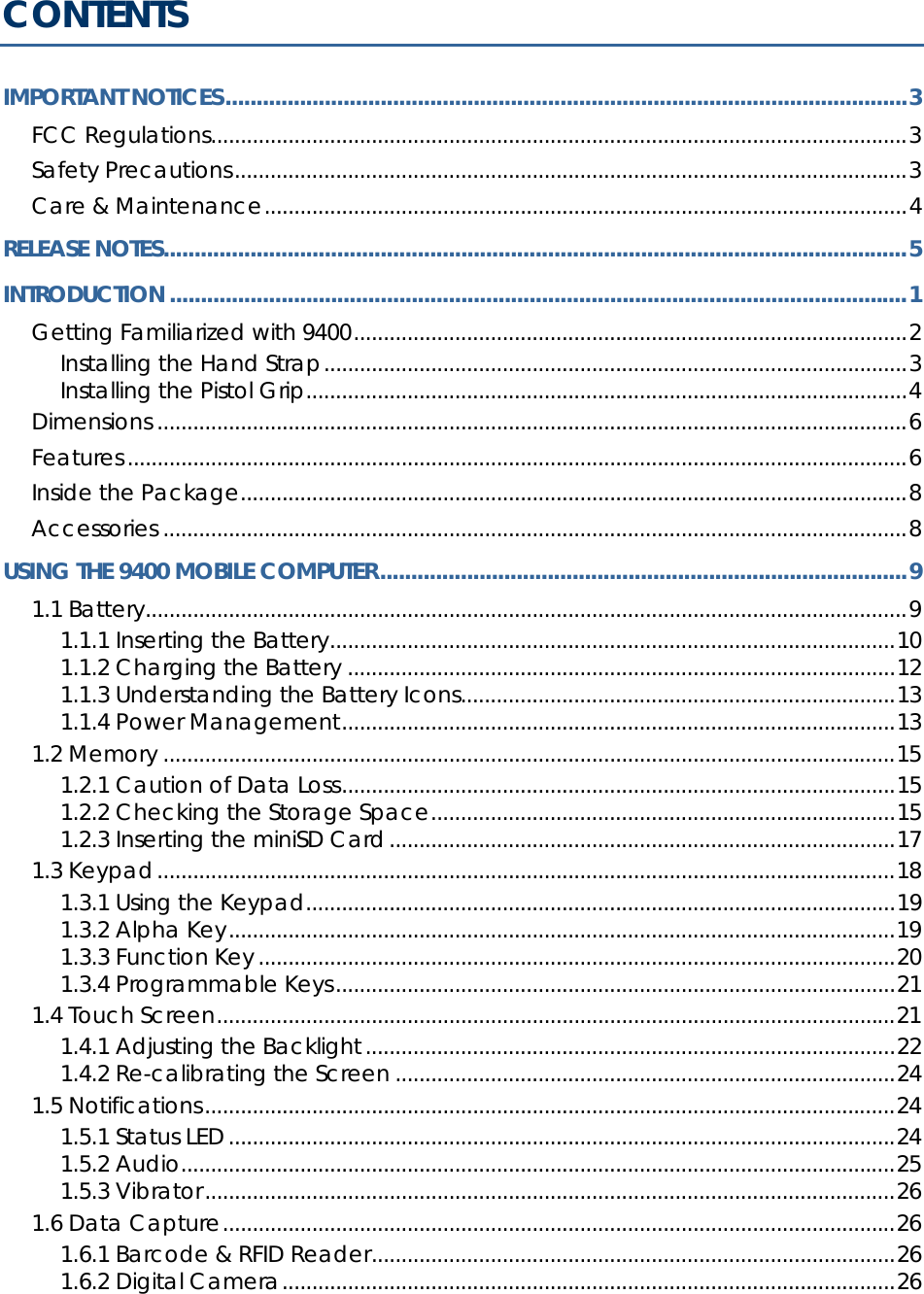
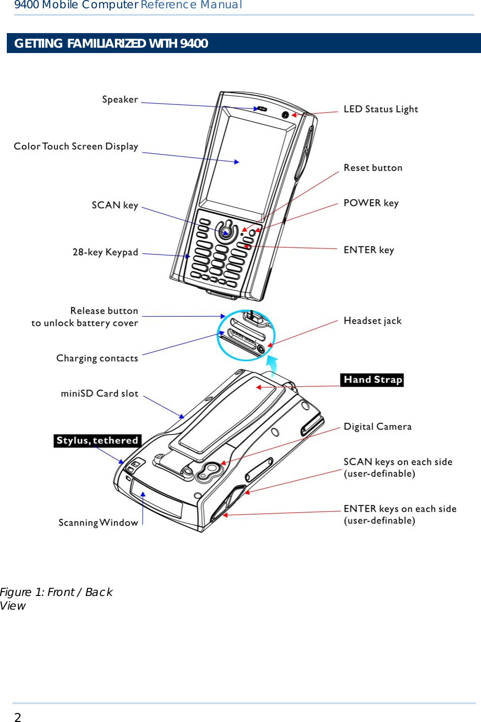
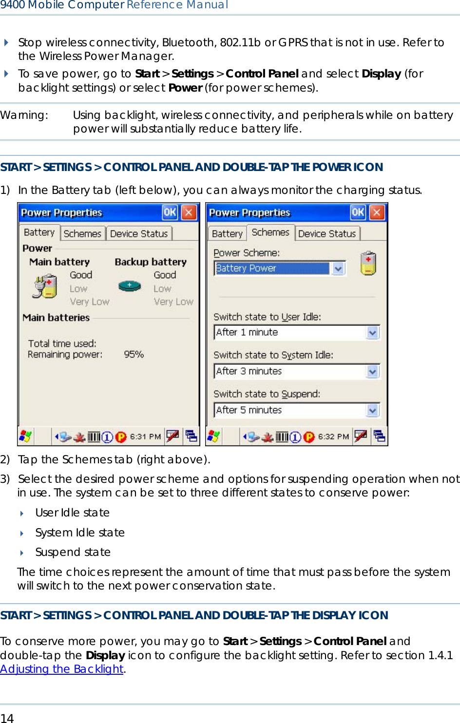
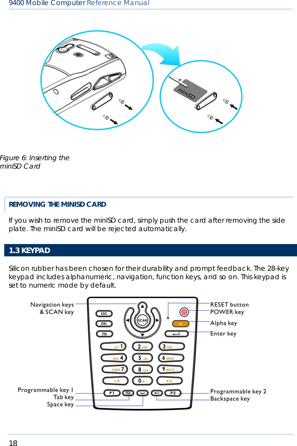
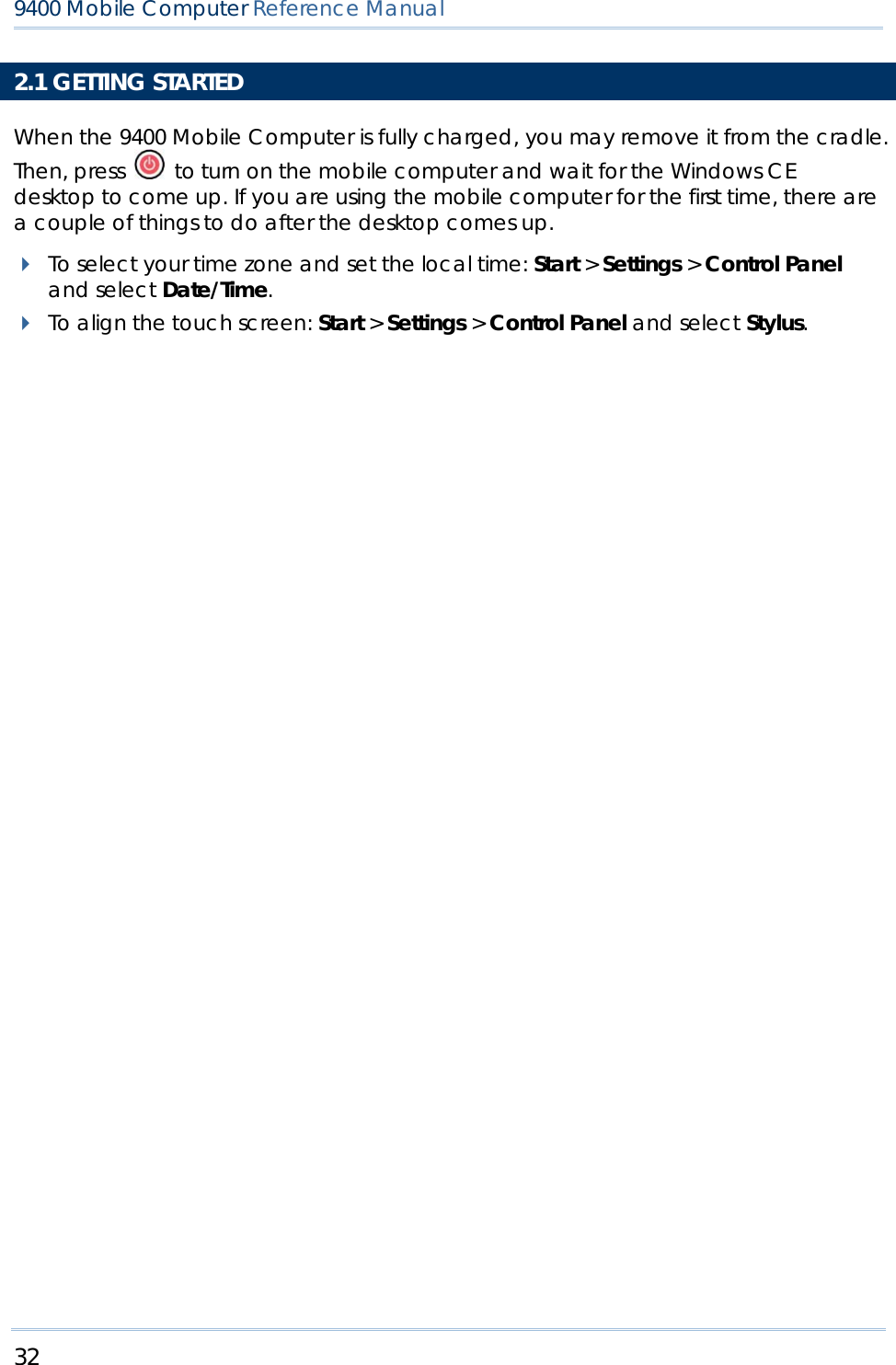
![24 9400 Mobile Computer Reference Manual 1.4.2 RE-CALIBRATING THE SCREEN This LCD is also a touch screen that can be calibrated through screen alignment. START > SETTINGS > CONTROL PANEL AND DOUBLE-TAP THE STYLUS ICON Tap the Calibration tab, and then tap the [Recalibrate] button. Warning: DO NOT use any pointed or sharp objects to move against the surface of the screen. 1.5 NOTIFICATIONS 1.5.1 STATUS LED The tri-color LED on top is used to provide information on the charging status or wireless power status. TASKS GREEN LED RED LED BLUE Charging 9400 --- On ---](https://usermanual.wiki/CipherLab/M0010A/User-Guide-915892-Page-32.png)

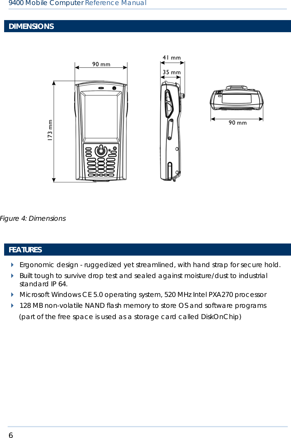
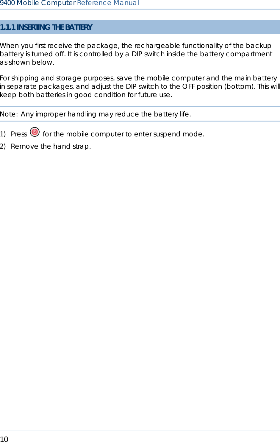
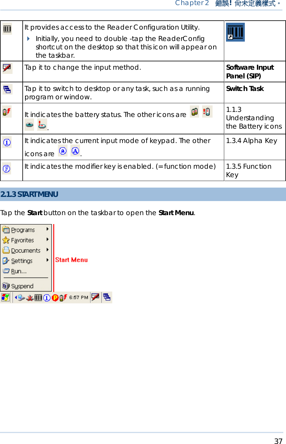
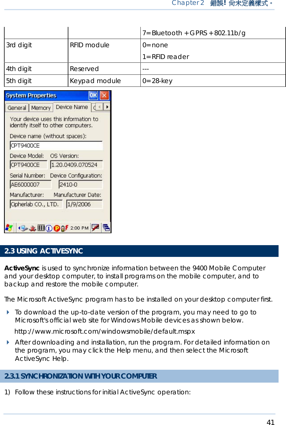
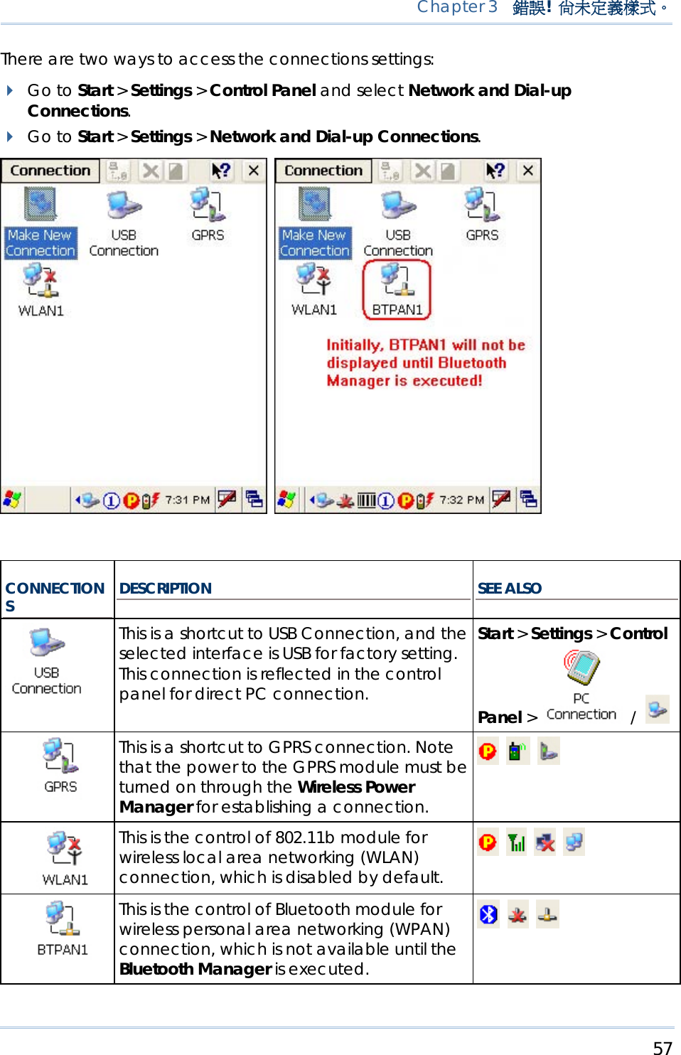
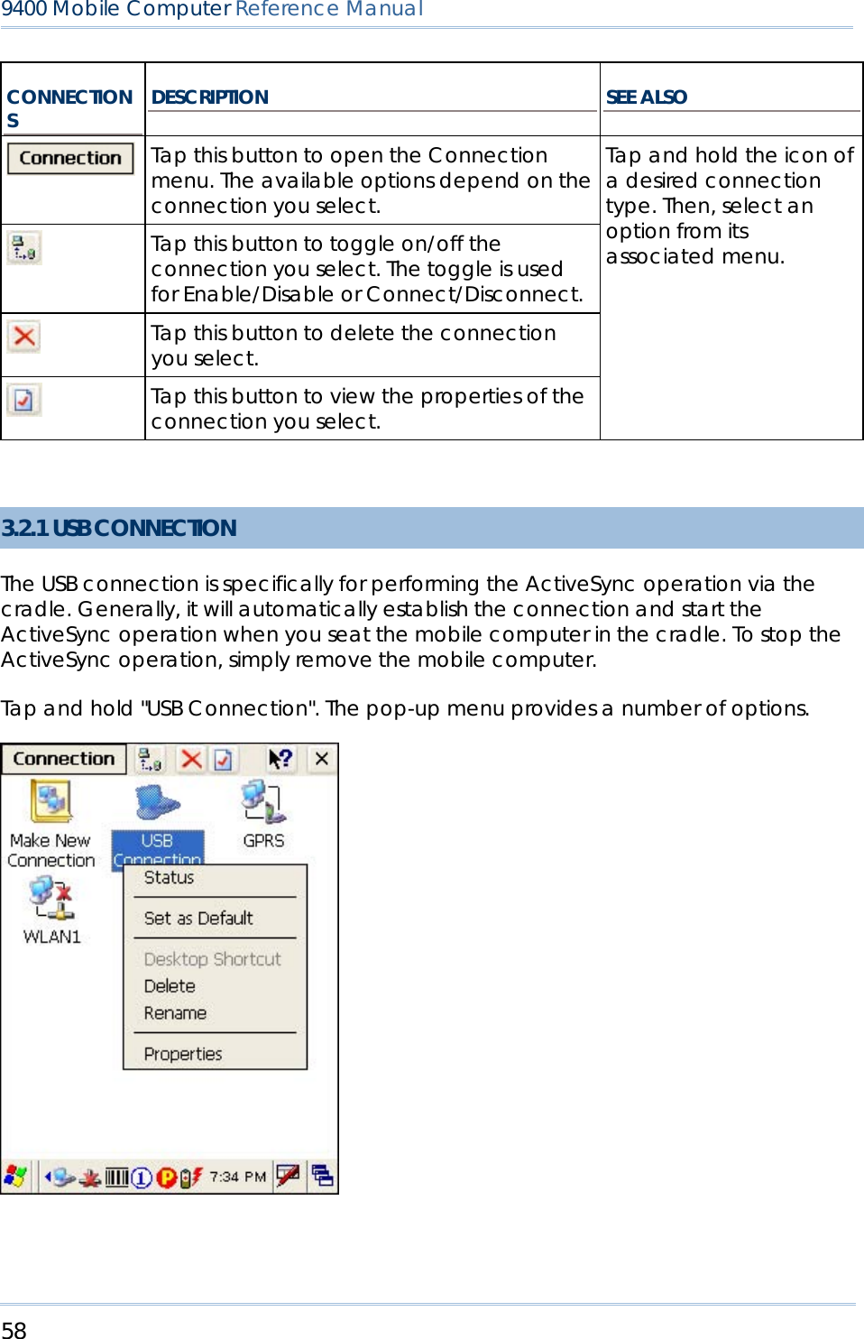
![36 9400 Mobile Computer Reference Manual UNDERSTANDING THE ICONS ON THE TASKBAR ICON DESCRIPTION SEE ALSO The USB connection for ActiveSync operation is successfully established. Double-tap it to view status. Tap [Disconnect] if necessary. 3.2.1 USB Connection (via cradle) The Bluetooth PAN connection fails. (= disconnected) The Bluetooth PAN connection is successfully established through the Bluetooth Manager utility. Double-tap it to view or renew IP Information. 3.2.4 BTPAN It provides control of the power to the 802.11b/g and GPRS modules. Double-tap any of these icons to configure the power setting. It indicates the GPRS module is enabled. See GPRS status icon below. It indicates the Wi-Fi module (802.11b) is enabled. See WLAN1 status icons below. 4.1 Wireless Power Manager The GPRS connection has been opened. If it fails, the icon will be gone. If the icon persists, it means the GPRS connection is successfully established. Double-tap it to view status. Tap [Disconnect] if necessary. 3.2.2 GPRS The Wi-Fi connection fails. (= disconnected) Double-tap it to access the Wireless Information tab for establishing a new connection. The Wi-Fi connection is successfully established. Double-tap it to view or renew IP & Wireless Information. 3.2.3 WLAN It provides access to the Bluetooth services. Initially, you need to go to Start > Programs > BTManager to open the Bluetooth Manager so that this icon will appear on the taskbar. 4.2 Bluetooth Manager](https://usermanual.wiki/CipherLab/M0010A/User-Guide-915892-Page-44.png)
![42 9400 Mobile Computer Reference Manual Connect the USB cable from the cradle's USB device port ( ) to your computer. Connect the power cable from the cradle to a nearby power outlet. Turn on the mobile computer and seat it in the cradle. 2) Your computer will automatically detect the USB device. Click [OK] when the connection is established. 3) Select which partnership to set up. If you want to synchronize data between the mobile computer and your personal computer, select Standard Partnership; otherwise, select Guest Partnership. 4) Wait a few seconds for the mobile computer to get connected (and synchronized if a Standard Partnership is selected). Note: (1) For ActiveSync via Bluetooth, refer to the Bluetooth Manager. (2) We recommend that you have ActiveSync 3.7.1 installed on your computer because ActiveSync 4.x does not officially support Windows CE 5.0 devices. 2.3.2 ADD/REMOVE PROGRAMS Click [Add/Remove Programs] from the Tools Menu so that you can proceed to install a program that is designed to be used on a mobile device running Windows CE. If a user program is no longer desired, you may remove it from the system. Click [Add/Remove Programs] from the Tools Menu so that you can proceed to un-install a program that is designed to be used on a mobile device running Windows CE.](https://usermanual.wiki/CipherLab/M0010A/User-Guide-915892-Page-50.png)
![43 Chapter 2 錯誤! 尚未定義樣式。 ALTERNATIVE TO INSTALL NEW PROGRAMS (COPY & PASTE) Alternatively, you may install a new program manually. 1) When connected, open the Microsoft ActiveSync window on your desktop computer. 2) Click the Explorer button from the toolbar. 3) Navigate to the target folder, e.g. the Programs folder, depending on where you wish to access the program. 4) Navigate through file folders on your computer to find the new program (.CAB, .EXE, etc.) 5) Right-click the program and select [copy] from the pop-up menu. 6) Back to the target folder in step 3. Right-click anywhere blank and select [Paste] from the pop-up menu. 7) On the mobile computer, go to Start > Programs and the new program will appear. ALTERNATIVE TO REMOVE PROGRAMS (CONTROL PANEL) Alternatively, you may un-install a new program manually. 1) Go to Start > Settings > Control Panel and select Remove Programs. 2) Tap the name of the program that you want to delete. 3) Tap [Remove]. 4) Tap [Yes] to un-install the program. Note: If the program does not appear in the list of installed programs, you may use Windows Explorer to locate it. Tap and hold the program to select [Delete] from the pop-up menu.](https://usermanual.wiki/CipherLab/M0010A/User-Guide-915892-Page-51.png)
![45 Chapter 2 錯誤! 尚未定義樣式。 If you wish to quick launch a new program, add it to the Programs folder: My Device\Windows\Programs. The program will become available in the Start Menu. To add a new program or subfolder to the Programs folder, you can either use Windows Explorer or ActiveSync. Windows Explorer: to move the program by [Copy] and [Paste Shortcut]. ActiveSync on the desktop computer: to create a shortcut to the program, and place the shortcut in the Programs folder. Warning: To avoid making any changes to the program configurations by accident, we recommend you to use [Copy] and [Paste Shortcut] rather than [Cut] and [Paste]. USING WINDOWS EXPLORER TO ADD A PROGRAM TO START MENU 1) Go to Start > Programs and select Windows Explorer. 2) Navigate through file folders to find the program you desire. 3) Tap and hold the program to select [Copy] from the pop-up menu (left below).](https://usermanual.wiki/CipherLab/M0010A/User-Guide-915892-Page-53.png)
![46 9400 Mobile Computer Reference Manual 4) Navigate to the Programs folder – My Device\Windows\Programs (right above). 5) Tap and hold anywhere blank on the screen to select [Paste Shortcut] from the pop-up menu. The new program will be added to the Programs folder. 6) Go to Start > Programs and the new program will appear now. USING ACTIVESYNC TO ADD A PROGRAM TO START MENU 1) When connected, open the Microsoft ActiveSync window on your desktop computer.](https://usermanual.wiki/CipherLab/M0010A/User-Guide-915892-Page-54.png)
![47 Chapter 2 錯誤! 尚未定義樣式。 2) Click the Explorer button from the toolbar. 3) Navigate through file folders to find the program you desire. 4) Right-click the program and select [Create Shortcut] from the pop-up menu. 5) Right-click the shortcut and select [Cut] from the pop-up menu. 6) Navigate to the Programs folder – My Device\Windows\Programs. 7) Right-click anywhere blank on the window and select [Paste] from the pop-up menu. The new program will be added to the Programs folder. 8) On the mobile computer, go to Start > Programs and the new program will appear now. Note: [Create Shortcut], [Cut], and [Paste]: The same result can be performed by [Copy] and [Paste Shortcut].](https://usermanual.wiki/CipherLab/M0010A/User-Guide-915892-Page-55.png)
![48 9400 Mobile Computer Reference Manual 2.4.2 CREATE A FOLDER USING WINDOWS EXPLORER TO ADD A NEW FOLDER 1) Go to Start > Programs and select Windows Explorer. 2) Navigate through file folders to find where you wish to create a new folder. 3) Right-click anywhere blank on the window and select [New Folder] from the pop-up menu. A subfolder will be created. USING ACTIVESYNC TO ADD A NEW FOLDER 1) When connected, open the Microsoft ActiveSync window on your desktop computer. 2) Click the Explorer button from the toolbar. 3) Navigate to the target folder where you wish to create a new folder. 4) Right-click anywhere blank on the window and select [New Folder] from the pop-up menu. A subfolder will be created. 2.4.3 SWITCH AMONG PROGRAMS AND DESKTOP Tap to the right of the taskbar and select a running program. 2.4.4 EXIT A PROGRAM In general, the system manages memory automatically, and there is no need to exit a program in order to open another or to conserve memory. However, random access memory (SDRAM) may be used up when running too many programs. As a result, it will slow down the operation or cause program errors. In that case, you should stop one or more running programs to free memory. In order to use memory in a more efficient way, you are recommended to exit a program when it is not desired any longer. Warning: Always remember to save data or settings before you exit a program.](https://usermanual.wiki/CipherLab/M0010A/User-Guide-915892-Page-56.png)
![49 Chapter 2 錯誤! 尚未定義樣式。 Tap or to close an active window, a dialog box, or a running application. If the button is not displayed on the toolbar, press on the physical keypad. Tap to save the current settings and exit the application (or minimize the window in some applications). If the button is not displayed on the toolbar, press on the physical keypad. Note: Some programs, such as the Reader Configuration Utility (94ReaderCfg.exe), may create an associated icon on the taskbar. You may tap the icon and select [Exit] from the pop-up menu. 2.5 SYSTEM RESET & AUTO RUN Reset the mobile computer when it stops responding to input. Software Reset: Simply press the [Reset] button. Hardware Reset: Press the [Reset] button and at the same time. Warning: Never perform a hardware reset unless a software reset cannot solve your problems. 2.5.1 SOFTWARE RESET (WARM REBOOT) A software reset, also known as a warm boot, will restart the mobile computer and keep all the saved files. To perform a software reset, use the stylus to press the [Reset] button. During operation, the removal of main battery will start a software reset too. Warning: Data loss may occur when files are not properly closed before a software reset. 2.5.2 HARDWARE RESET (COLD REBOOT) A hardware reset, also known as a cold boot, will restart the mobile computer too. However, it performs a full restore of the mobile computer to its factory settings and initializes SDRAM. To perform a hardware reset, press and [Reset] button at the same time. Data and program files stored in SDRAM will be erased after a hardware reset. But you can restore data that is previously synchronized with your computer by performing an ActiveSync operation.](https://usermanual.wiki/CipherLab/M0010A/User-Guide-915892-Page-57.png)
![51 Chapter 2 錯誤! 尚未定義樣式。 2) Run DLDR.exe on your computer. 3) Press [Reset] + to perform a hardware reset on 9400. 4) Press + simultaneously in three seconds so that 9400 can enter the "Download" mode. 5) Seat 9400 in the cradle. 6) Press on 9400 to start image update. It will take approximately 5 minutes to update the image. A message will be displayed on the mobile computer to indicate the OS update is completed successfully. 7) Wait a few seconds for a software reset will be performed automatically. 8) Press [Reset] + to perform a hardware reset on 9400 again. Warning: Do not press any key on the mobile computer while updating OS image. Once the OS update is completed, you cannot reload any older image.](https://usermanual.wiki/CipherLab/M0010A/User-Guide-915892-Page-59.png)
![53 In this chapter, a brief on the system settings is provided for your reference. Note: User settings are stored in SDRAM and will be overwritten by the system defaults after a hardware reset. However, you can use the CipherLab Backup Utility to backup the current registry for restore purpose. IN THIS CHAPTER 3.1 Changing System Settings .................................................... 53 3.2 Changing Connection Settings ........................................... 56 3.1 CHANGING SYSTEM SETTINGS Go to Start > Settings > Control Panel. ITEMS DESCRIPTION In the [Accessibility] dialog box, you may use these options to customize the way an external keyboard, display, or mouse functions. Many of these features are useful to people without disabilities Chapter 3 PERSONALIZING THE 9400 MOBILE COMPUTER](https://usermanual.wiki/CipherLab/M0010A/User-Guide-915892-Page-61.png)
![54 9400 Mobile Computer Reference Manual Keyboard tab: Select StickyKeys to enable simultaneous keystrokes while pressing one key at a time; select ToggleKeys to emit sounds when certain locking keys are pressed. Sound tab: Select SoundSentry to provide visual warnings for system sounds. Display tab: Select High Contrast to improve screen contrast with alternative colors. Mouse tab: Select MouseKeys to enable the keyboard to perform mouse functions General tab: Select Automatic Reset if you wish to turn off accessibility features after a specific period of time; select Notification if you wish to hear a sound when turning a feature on or off. In the [Certificates] dialog box, you may view or modify digital certificates that some application use to establish trust for secure connections. In the [Date/Time] dialog box, you may change date, time, and time zone settings. In the [Dialing Properties] dialog box, you may configure settings for modem communications, such as the GPRS modem. In the [Display Properties] dialog box, Background tab: Select an image for the background. Appearance tab: Select a desired color scheme for windows, dialog boxes, and items. Backlight tab: Specify for how long the mobile computer is idle and then the backlight will be automatically turned off while on battery power and external power (in the charging cradle) respectively. Tap the [Advanced] button to move the slider and adjust the brightness of the LCD backlight when it is set to be automatically turned on once a key is pressed or you tap the touch screen. In the [Input Panel Properties] dialog box, you may configure how the Soft Input Panel (SIP) works. In the [Internet Options] dialog box, you may configure how the mobile computer connects to the Internet.](https://usermanual.wiki/CipherLab/M0010A/User-Guide-915892-Page-62.png)
![55 Chapter 3 錯誤! 尚未定義樣式。 Connect an external keyboard to the cradle via the USB Host port. In the [Keyboard Properties] dialog box, you may configure settings for character repeat. Connect a mouse to the cradle via the USB Host port. In the [Mouse Properties] dialog box, you may configure and test your double-click settings. In the [Network and Dial-up Connections] window, you may configure settings for the mobile computer connects to a network directly or through a modem. Alternatively, you may tap Start > Settings > Network and Dial-up Connections. USB Connection (via USB device port on the cradle) GPRS (through a GPRS modem) WLAN (via 802.11b/g) BTPAN (via Bluetooth) In the [Owner Properties] dialog box, Identification/Notes tab: Type your contact information or notes. Network ID tab: Type the user name, password, and domain name used to log on to the remote network. In the [Password Properties] dialog box, you may apply password protection to limit access to the mobile computer. In the [PC Connection Properties] dialog box, you may disable the direct connection between the mobile computer and a desktop computer. By default, the mobile computer is enabled to directly connect to a desktop computer via the cradle's USB port. Alternatively, you may tap Start > Settings > Network and Dial-up Connections and select USB Connection. You may change to use Bluetooth if ActiveSync via Bluetooth has been enabled in the Bluetooth Manager In the [Power Properties] dialog box, Battery tab: You may view the current status of main and backup batteries. Schemes tab: You may configure the power scheme and switching. Device Status tab: You may view the devices that are consuming power.](https://usermanual.wiki/CipherLab/M0010A/User-Guide-915892-Page-63.png)
![56 9400 Mobile Computer Reference Manual In the [Regional and Language Settings] dialog box, Region tab: You may customize the appearance and formatting to your geographic region. Language tab: By default, it is set to English (United States). Input tab: By default, it is set to English (United States)-US. In the [Remove Programs] dialog box, you may remove any program that is installed earlier. In the [Storage Properties] dialog box, Storage Manager tab: You may reformat the available storage device, either the DiskOnChip folder or storage card. Actions include "Dismount the storage device", "Format the storage device", and "Set up disk partitions". The Storage Manager is for the use of system administrators only. In the [Stylus Properties] dialog box, Double-Tap tab: You may configure and test your double-tap settings. Calibration tab: You may need to re-calibrate the touch screen if it is not responding properly to your taps. In the [System Properties] dialog box, General tab: You may view the system information. Memory tab: You may move the slider and adjust the SDRAM allocation. Device Name tab: You may type a name and description for identifying the mobile computer. Copyrights tab: You may view the important statements on copyrights. Client access licenses (CALs) issued by the Terminal Server license server allow clients to connect to the terminal server. Use Remote Desktop Connection to log onto a Windows Terminal Server or a computer remotely. You may access all of the programs, files, and network resources on the remote host or terminal server. In the [Volume & Sounds Properties] dialog box, Volume tab: You may move the slider and adjust the volume and select to play sounds for Events, Applications or Notifications. Sounds tab: You may configure sounds for different Windows events. 3.2 CHANGING CONNECTION SETTINGS](https://usermanual.wiki/CipherLab/M0010A/User-Guide-915892-Page-64.png)
![59 Chapter 3 錯誤! 尚未定義樣式。 Note: Please ignore [Properties] as the associated settings will not take effect. STATUS - DISCONNECT If you want to stop the ActiveSync operation without removing the mobile computer from the cradle, select [Status] and tap [Disconnect]. Alternatively, you may double-tap from the taskbar and tap [Disconnect]. When connected, the status icon will appear on the taskbar. When disconnected, this icon will disappear. 3.2.2 GPRS Tap and hold "GPRS". The pop-up menu provides a number of options. Refer to section 1.7.2 Inserting the SIM Card. CONNECT/DISCONNECT 1) Turn on the power to the GPRS module through the Wireless Power Manager. Its associated icon on the taskbar will become .](https://usermanual.wiki/CipherLab/M0010A/User-Guide-915892-Page-67.png)
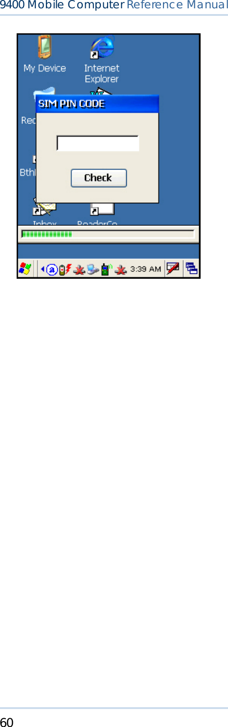
![61 Chapter 3 錯誤! 尚未定義樣式。 2) If the default PIN code does not match the one of your SIM card, the SIM PIN CODE dialog box (above) will appear to request the correct PIN code. You will have two chances to enter the correct PIN code. Note: The PIN verification on the mobile computer only allows two attempts because the system will always process the default number first ("1234" for factory setting). Unless it matches the PIN code of your SIM card, you will have to manually input the correct PIN code. If you succeed, the PIN code you input will overwrite the factory setting and become the default PIN code. If you fail two times, the PIN will be blocked. 3) Go to Start > Settings > Network and Dial-up Connections. Tap and hold "GPRS" to select [Connect] from the pop-up menu. If your dial-up configuration is correct, simply tap the [Connect] button in the Dial-Up Connection dialog box. If you need to configure the dial-up settings, tap the [Dial Properties] button.](https://usermanual.wiki/CipherLab/M0010A/User-Guide-915892-Page-69.png)
![62 9400 Mobile Computer Reference Manual Alternatively, you may go to Start > Settings > Control Panel and select Dialing. 4) After you tap the [Connect] button, the GPRS status will go through opening port, user authenticated, device connected until it is connected finally. The status icon will appear on the taskbar to indicate the GPRS connection is established successfully. If you want to disconnect, double-tap the icon and tap the [Disconnect] button.](https://usermanual.wiki/CipherLab/M0010A/User-Guide-915892-Page-70.png)
![63 Chapter 3 錯誤! 尚未定義樣式。 GPRS PROPERTIES When selected, you can configure the GPRS properties. Once the SIM card is inserted, the default GPRS modem will appear as shown below. Tap [Configure]. Select the Call Options tab. The special modem commands inserted into the dial string must be [+CGDCONT=1,,"AP name"]. For example, change "INTERNET" below to the name of your GPRS AP.](https://usermanual.wiki/CipherLab/M0010A/User-Guide-915892-Page-71.png)
![65 Chapter 3 錯誤! 尚未定義樣式。 CONNECT/DISCONNECT Turn on the power to the 802.11b/g module through the Wireless Power Manager. Wait a few seconds for the mobile computer to automatically connect to the preferred network you have configured. CONNECTION ICONS DESCRIPTION By default, the 802.11b/g module is disabled. No status icon. Enable the 802.11b/g module through the Wireless Power Manager. The icon on the taskbar will become , and the status icon will appear. When successfully connecting to an access point or other Wi-Fi enabled device, the status icon will become . Note: By default, DHCP is enabled. Instead of using DHCP, select [Properties] and specify a static IP address to the mobile computer. Only change these settings according to your network administrator's instructions. INITIAL CONNECTION 1) For initial connection, turn on the power to the 802.11b/g module through the Wireless Power Manager first. 2) Double-tap on the taskbar. 3) Select an available network and tap [Connect].](https://usermanual.wiki/CipherLab/M0010A/User-Guide-915892-Page-73.png)
![66 9400 Mobile Computer Reference Manual Otherwise, you may double-tap [Add New...] and add a new network option. For more network settings, tap [Advanced] on the Wireless Information tab. If you need to change the network settings, double-tap the selected network, and the Wireless Properties dialog box appears for configuration.](https://usermanual.wiki/CipherLab/M0010A/User-Guide-915892-Page-74.png)
![67 Chapter 3 錯誤! 尚未定義樣式。 RSSI TRIGGER RSSI stands for Received Signal Strength Indication. Use an RSSI value to determine when it comes below a certain threshold at which point the mobile computer will seamlessly switch the network connection, for example, while moving in and out of range between different access points. Select [Adaptive Connection] and pick up a suitable value. Cancel the selection of [Adaptive Connection] when you are using a third-party application capable of configuring the switching itself in order to maintain a constant connection to the network.](https://usermanual.wiki/CipherLab/M0010A/User-Guide-915892-Page-75.png)
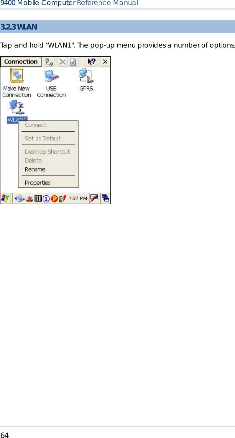
![68 9400 Mobile Computer Reference Manual 3.2.4 BTPAN Tap and hold "BTPAN1". The pop-up menu provides a number of options. ENABLE/DISABLE CONNECTION ICONS DESCRIPTION This is the control of Bluetooth module for wireless personal area networking (WPAN) connection, which is not available until the Bluetooth Manager is executed. When enabled, the status icon will become . Tap and hold "BTPAN1" to select [Disable] from the pop-up menu. The status icon will disappear. Note: By default, DHCP is enabled. Instead of using DHCP, select [Properties] and specify a static IP address to the mobile computer. Only change these settings according to your network administrator's instructions.](https://usermanual.wiki/CipherLab/M0010A/User-Guide-915892-Page-76.png)

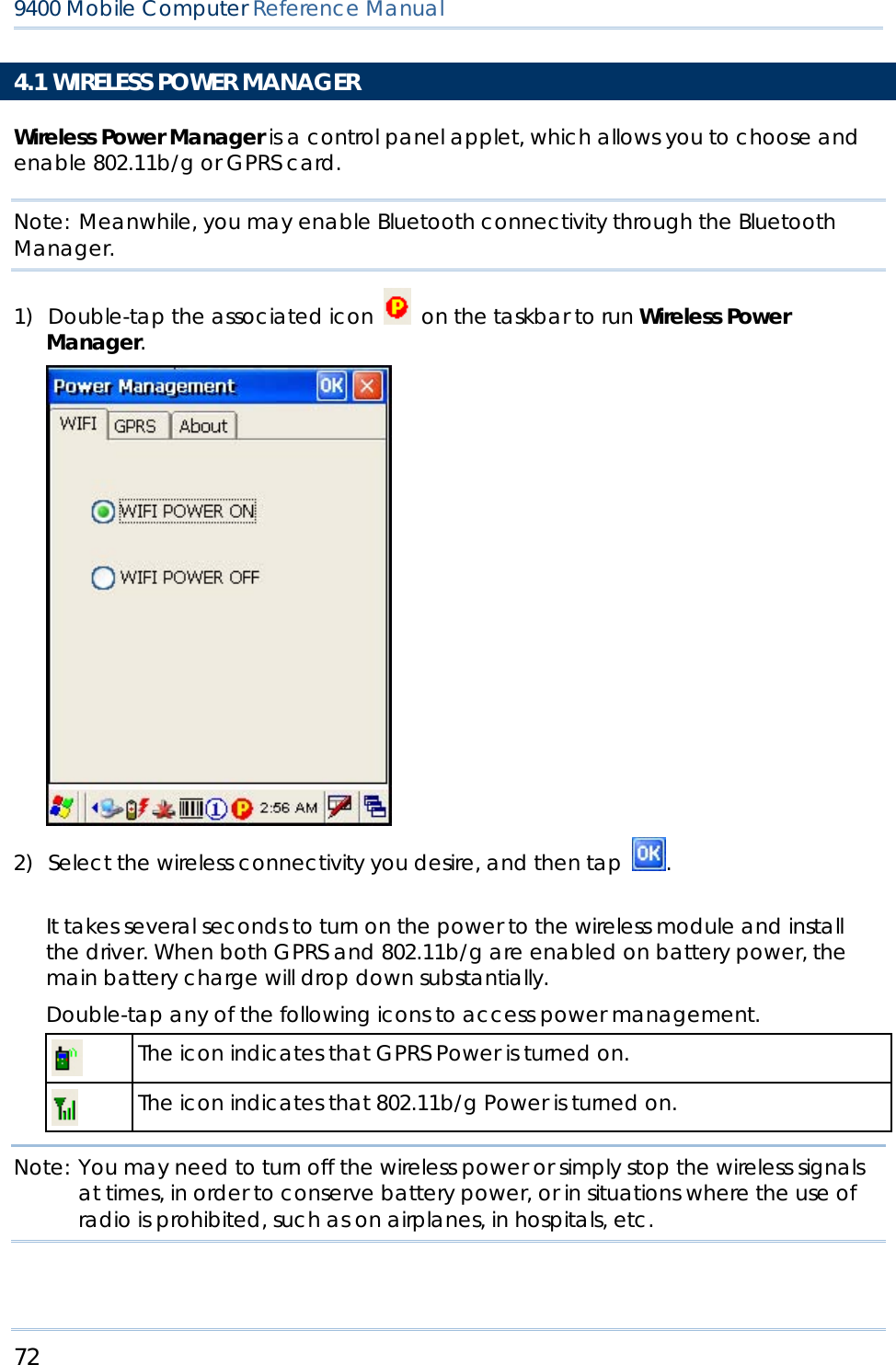
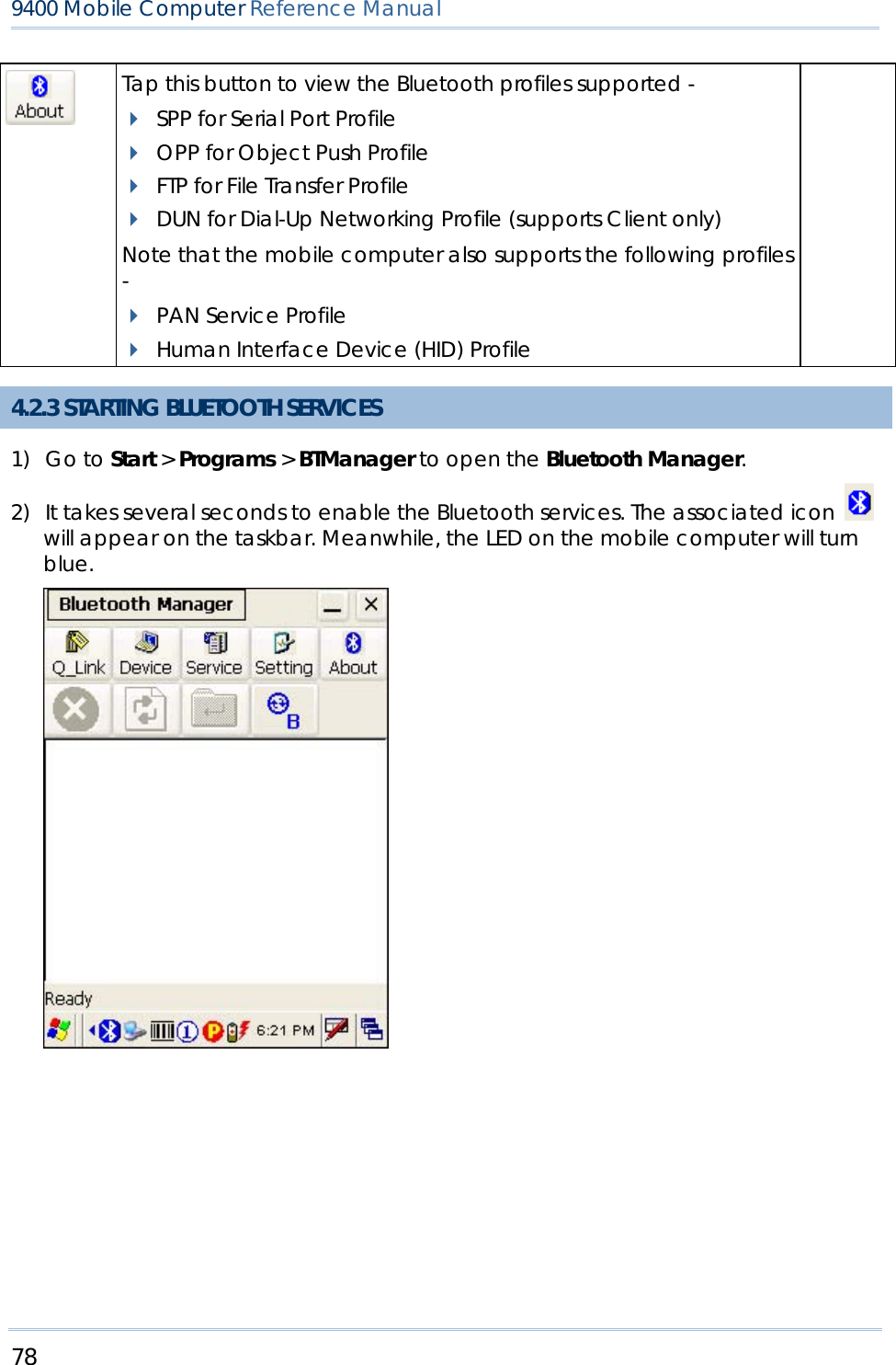
![74 9400 Mobile Computer Reference Manual 4.2.2 BLUETOOTH TOOLBAR BUTTONS DESCRIPTION SEE ALSO Tap this button to view shortcuts to preferred Bluetooth services, which may be provided on different Bluetooth devices. Then tap a desired Bluetooth service to establish a quick link. You will have to make a connection and created a shortcut to a specific Bluetooth service first. Tap this button to view the Bluetooth devices discovered during this session. If you tap the button for the first time, it will start the inquiry process to discover nearby Bluetooth devices. Tap this button to view the Bluetooth services provided. By default, these services are all available, and therefore, displayed along with a plug icon " ". To view properties of a service, tap and hold it to select [Properties] from the pop-up menu. To disable a service, tap and hold it to select [Stop].](https://usermanual.wiki/CipherLab/M0010A/User-Guide-915892-Page-82.png)
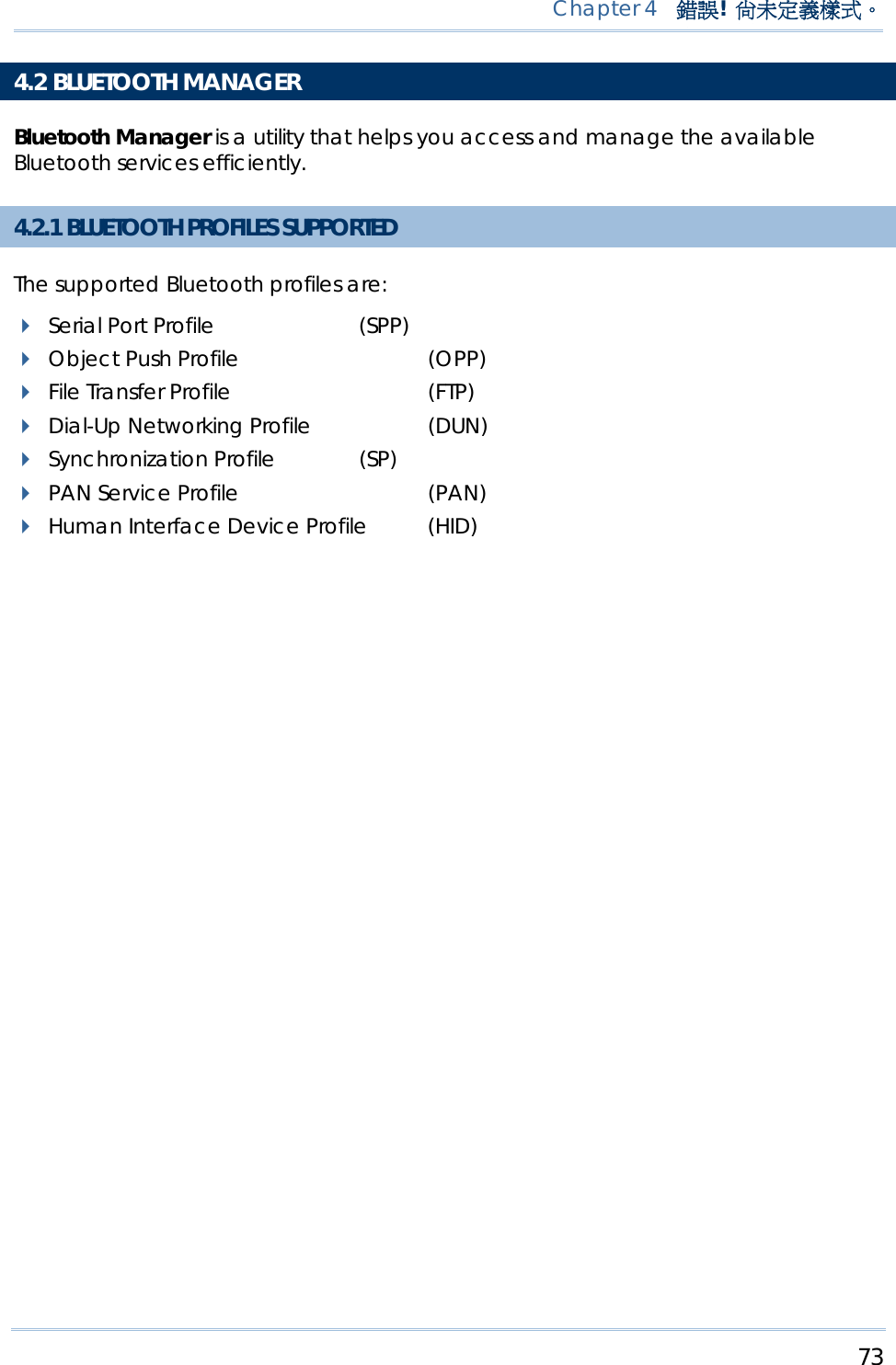
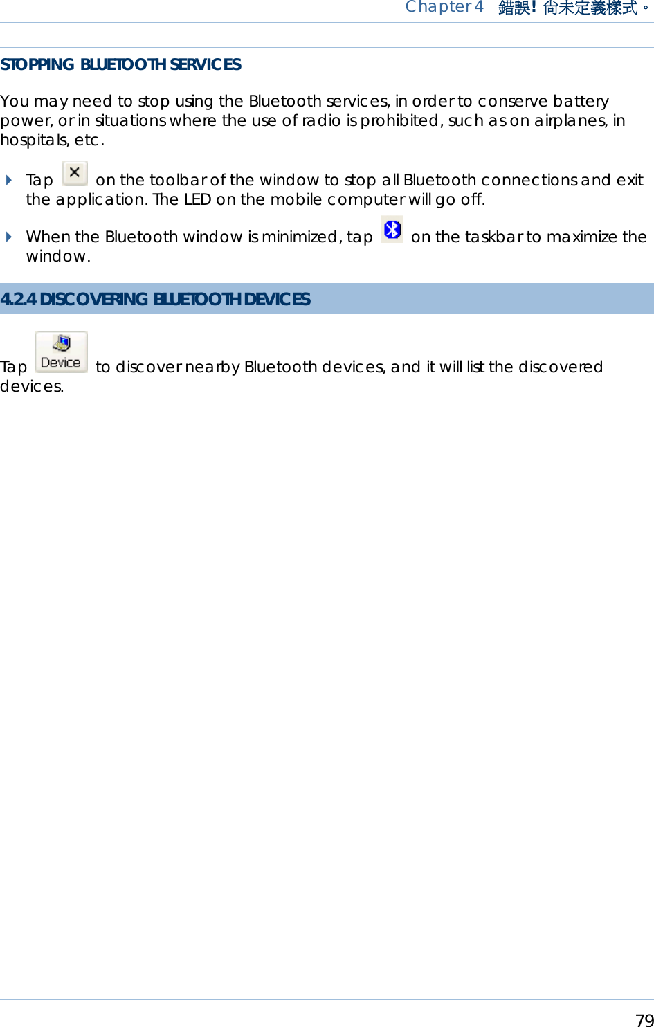
![77 Chapter 4 錯誤! 尚未定義樣式。 Options tab Start minimized: When selected, once you run the Bluetooth Manager program, its window will be minimized to an icon on the taskbar, which serves as a toggle to open or close the Bluetooth Manager window. It works the same as the "Minimized" button below. Auto Client COM Port: When enabled, the default COM port for remote Serial Port service will be assigned automatically. When disabled, you can select a COM port. Auto Server COM Port: When enabled, the COM port for local Serial Port service will be assigned automatically. Tap this button and tap [Connect via Cradle] to stop ActiveSync via Bluetooth. Tap this button to minimize the Bluetooth Manager window. Tap this button to exit the Bluetooth Manager. Tap this button to stop inquiring. Tap this button to refresh the device list. When using the File Transfer service on a remote device, you can tap this button to move up one level if a subfolder exists.](https://usermanual.wiki/CipherLab/M0010A/User-Guide-915892-Page-85.png)
![80 9400 Mobile Computer Reference Manual 4.2.5 PAIRING When authentication is enabled on the target device, you will have to pair with it before starting a connection. 1) From the device list, tap and hold the desired device to select [Pair] from the pop-up menu. (left below) 2) Enter the PIN code that is specified on the remote device. (right above)](https://usermanual.wiki/CipherLab/M0010A/User-Guide-915892-Page-88.png)
![81 Chapter 4 錯誤! 尚未定義樣式。 3) Once paired successfully, the paired device will be displayed along with a lock icon " ". UNPAIR DEVICES To unpair with a device from the device list, you will have to tap and hold the desired device to select [Unpair] from the pop-up menu. Note: The mobile computer must be unpaired on the remote device as well. (Both devices must be unpaired!) 4.2.6 CONNECTING 1) From the device list above, double-tap a device to find out the available Bluetooth services. 2) Tap and hold a desired Bluetooth service, e.g. Serial Port Service, to select [Connect] from the pop-up menu. Once the connection has been established, the connected service will be displayed along with a plug icon " ".](https://usermanual.wiki/CipherLab/M0010A/User-Guide-915892-Page-89.png)
![82 9400 Mobile Computer Reference Manual 3) If you wish to add a service to the Q_Link list for establishing a quick connection in the future, tap and hold the service to select [Create Shortcut] from the pop-up menu.](https://usermanual.wiki/CipherLab/M0010A/User-Guide-915892-Page-90.png)
![83 Chapter 4 錯誤! 尚未定義樣式。 BLUETOOTH ACTIVESYNC For ActiveSync via Bluetooth, tap and hold Serial Port Service to select [Connect to Activesync] from the pop-up menu. It uses COM8 to connect to your computer by default. To stop ActiveSync via Bluetooth, tap and then tap [Connect via Cradle].](https://usermanual.wiki/CipherLab/M0010A/User-Guide-915892-Page-91.png)
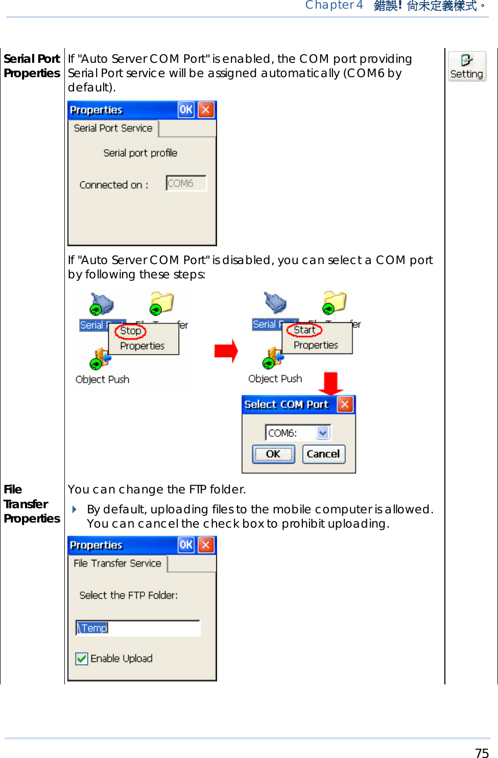
![84 9400 Mobile Computer Reference Manual USING SERIAL PORT SERVICE Tap and hold Serial Port Service to select [Connect] from the pop-up menu. If "Auto Client COM Port" is disabled in , you will need to select a COM port. Once the connection has been established, the connected service will be displayed along with a plug icon " ". USING OBJECT PUSH SERVICE 1) Tap and hold the Object Push service. 2) Select [Push file] to send a file or PIM item, e.g. a business card. (left below) 3) Choose the file you wish to send. (right below) 4) The mobile computer will start transferring the file. USING FILE TRANSFER SERVICE 1) Tap and hold the File Transfer service.](https://usermanual.wiki/CipherLab/M0010A/User-Guide-915892-Page-92.png)
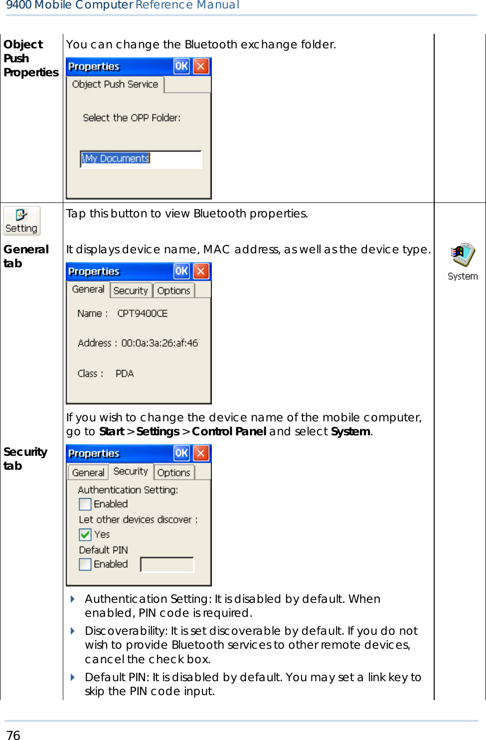
![85 Chapter 4 錯誤! 尚未定義樣式。 2) Select [Connect] (and assign COM port if necessary). 3) Tap and hold anywhere blank to select [Add file] from the pop-up menu. 4) Choose the file you wish to upload to the remote device. 5) The mobile computer will start transferring the file. 6) To download a file from the remote device, tap and hold a desired file to select [Get file] from the pop-up menu.](https://usermanual.wiki/CipherLab/M0010A/User-Guide-915892-Page-93.png)
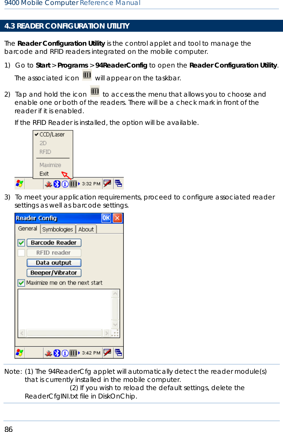
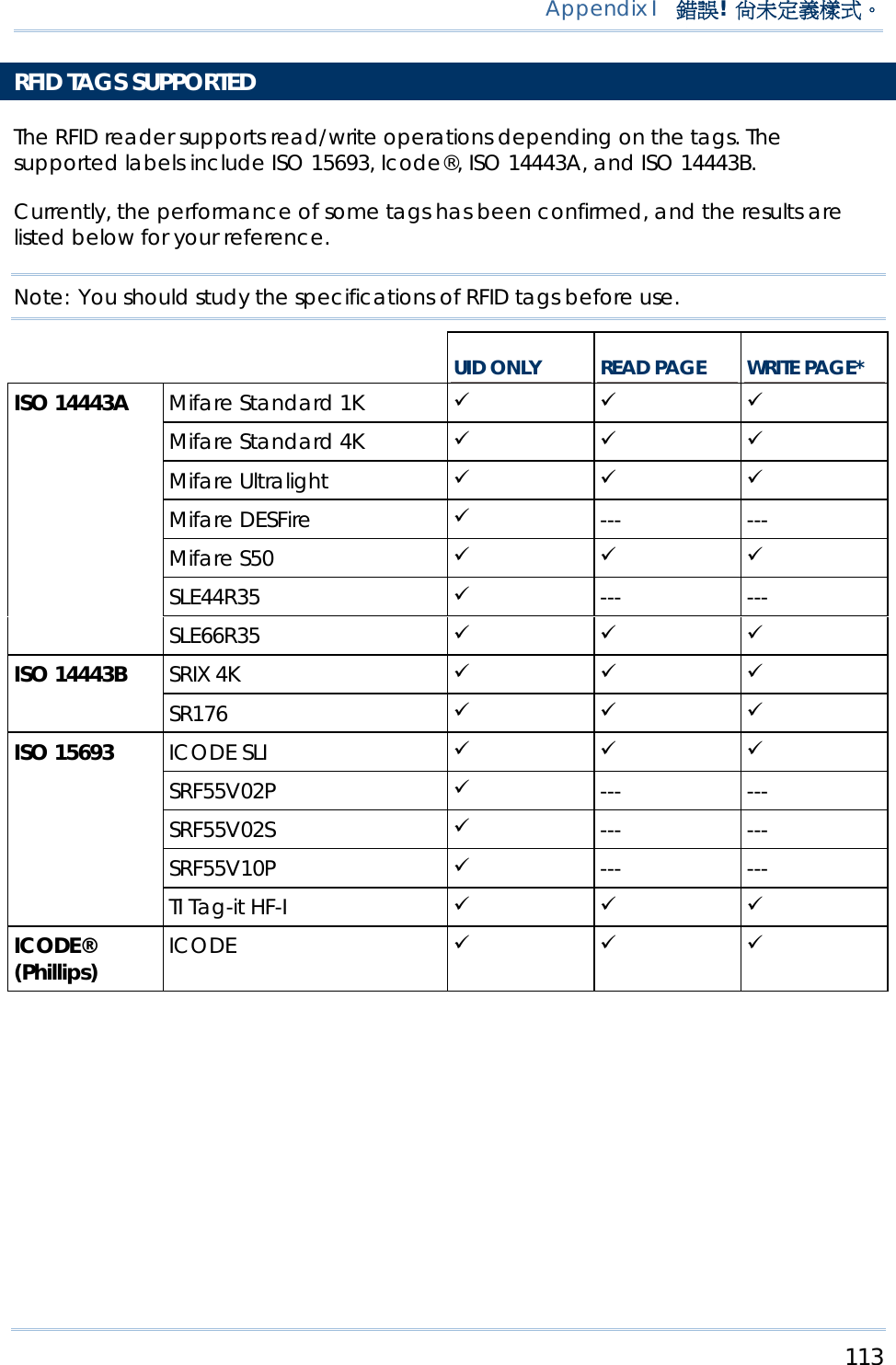
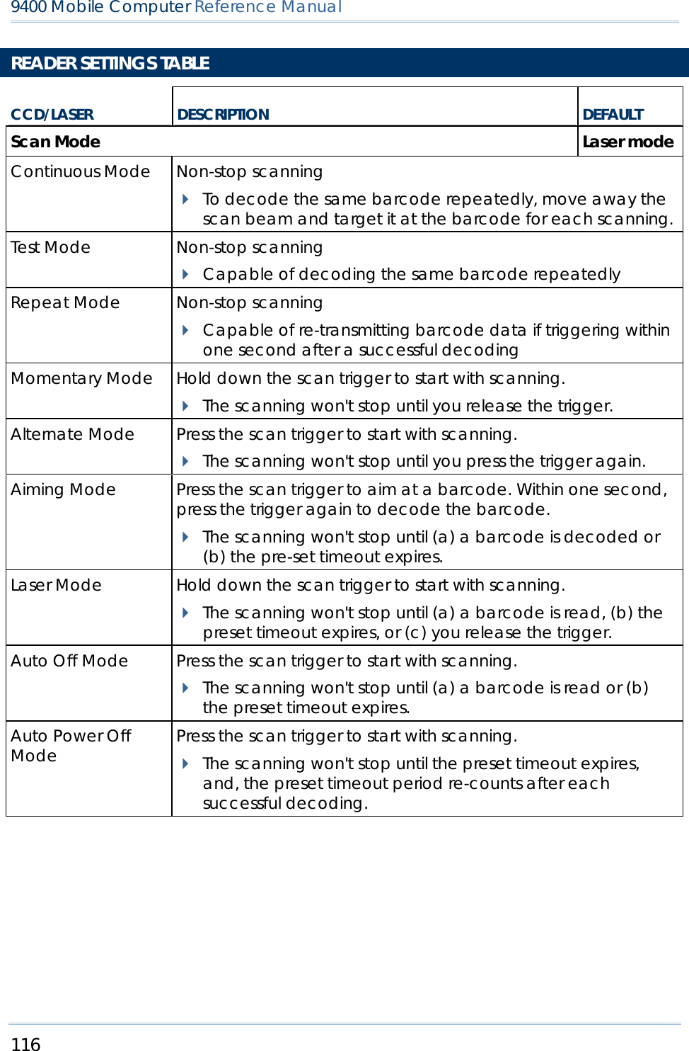
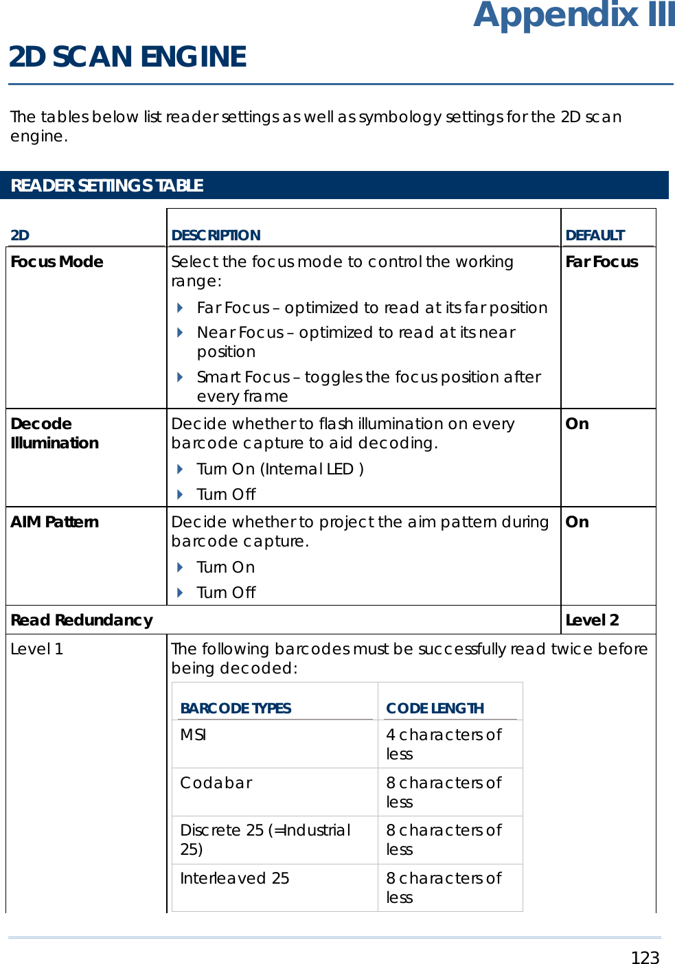
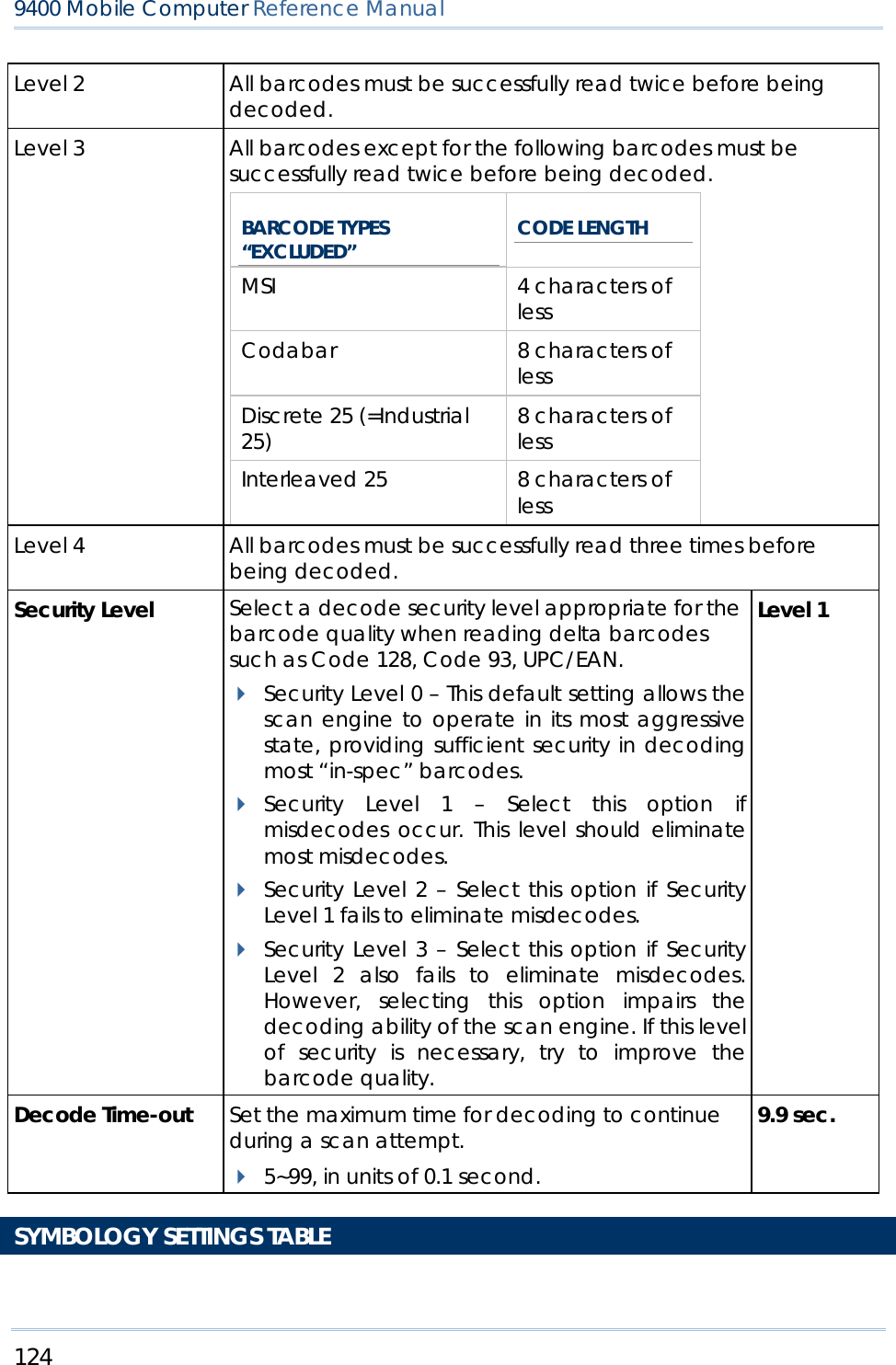
![87 Chapter 4 錯誤! 尚未定義樣式。 4.3.1 BARCODE READER SETTINGS The barcode reader configurations depend on the scan engine(s) installed. You can tell which reader is currently in use and make necessary changes on the General tab. BARCODE READER DESCRIPTION CCD/Laser Reader If enabled, tap the [Barcode Reader] button to configure the reader settings for CCD or Laser scan engine. Refer to the Reader Settings Table in Appendix II – CCD/Laser Scan Engine. 2D Reader The 2D scan engine is capable of reading linear and 2D barcodes. If enabled, tap the [Barcode Reader] button to configure the reader settings for 2D scan engine. Refer to the Reader Settings Table in Appendix III – 2D Scan Engine. 4.3.2 RFID READER SETTINGS If the RFID scan engine is present, configurable options will be displayed. Note: Because it is possible to read barcode and RFID tag at the same time, it is recommended that only one scan engine is enabled at a time to prevent from misreading. Some RFID tags support both read/write operations, on a page-by-page basis. You may find it necessary to define your own read/write operation. For reference only, the table below lists the start page for read/write operation on a number of RFID tags. START PAGE TAG TYPE -1 Start from byte 0 of the default page (see below) for all tags 3 Mifare Ultralight (ISO 14443A) 4 SR176 (ISO 14443B) 3 ICODE SLI (ISO 15693) 0 LRI512 (ISO 15693) 3 SRF55VxxP (ISO 15693) 0 EM4135 (ISO 15693)](https://usermanual.wiki/CipherLab/M0010A/User-Guide-915892-Page-95.png)
![88 9400 Mobile Computer Reference Manual 0 Tag-it HF-I (ISO 15693) 0 Others (ISO 15693) 5 ICODE (Phillips) Note: Please refer to the specifications of your RFID tags for memory organization. READ OPERATION By default, the RFID tag is read from byte 0 of the default page. However, the default page, amount of bytes and number of pages of each tag may be different. Specify how many bytes of data you want to read from the tag. Generally, the read data is user data obtained from the user block. If you are sure that the data is to be read from a non-user block, such as the lock block, you need to select the check box of [Display hex values] first. WRITE OPERATION Type the string that you want to write to a tag. By default, the string is written to the tag from byte 0 of the default page. However, the default page, amount of bytes and number of pages of each tag may be different. Therefore, the input string will automatically be truncated to fit into pages, and data may be discarded when it comes to the end of pages available. Generally, it will write the input string to the user block, which is free for custom use. The string will be displayed as “user data”. If you wish to write the string to a non-user block, such as the lock block, you need to select the check box of [Use hex values] first. Once you have selected to use hex values for the string, make sure the string length must be even. For example, if you want to write 0x0A, 0x0B and 0x00 to a tag, the string you input must be “0A0B00” instead of “AB0”. 4.3.3 DATA OUTPUT Tap the [Data Output] button on the General tab to choose from the three options for data output after decoding as well as configure associated settings DATA OUTPUT DEFAULT](https://usermanual.wiki/CipherLab/M0010A/User-Guide-915892-Page-96.png)
![89 Chapter 4 錯誤! 尚未定義樣式。 Keyboard Emulation Data is emulated as typed text and sent to the active Window. Simply run your application or Pocket PC built-in program, such as Pocket Excel, to start with data collection. Enable Windows Message When selected, a Windows message will be broadcasted after decoding. Intercept the decode message in your application. Call Windows API (ReadMsgQueue) in your application to retrieve the decoded data. Disable Windows Event When selected, a Windows event will be broadcasted after decoding. Intercept the decode event in your application. Call Windows API (ReadMsgQueue) in your application to retrieve the decoded data. Disable Note: (1) Refer to 9400 Programming Guide for details on Windows Message and Windows Event. Sample programs are provided by request. (2) For the use of a different program rather than 94ReaderCfg, a dynamic-link library (DLL) file is provided. Auto ENTER This function can spare you the trouble of pressing the [Enter] key on the mobile computer to confirm each scan. It will automatically add an ENTER character in front or to the end of one scan. No Scan + ENTER (time-saving) ENTER + Scan (efficient for continuous scanning) Scan + ENTER Auto ENTER Character *Auto ENTER must be enabled. None Carriage Return Tab Space Comma Semicolon Carriage Return Prefix String 0~10 characters NULL Suffix String 0~10 characters NULL Display Code Type Select the check box to display the code type after decoding a barcode. Disabled](https://usermanual.wiki/CipherLab/M0010A/User-Guide-915892-Page-97.png)
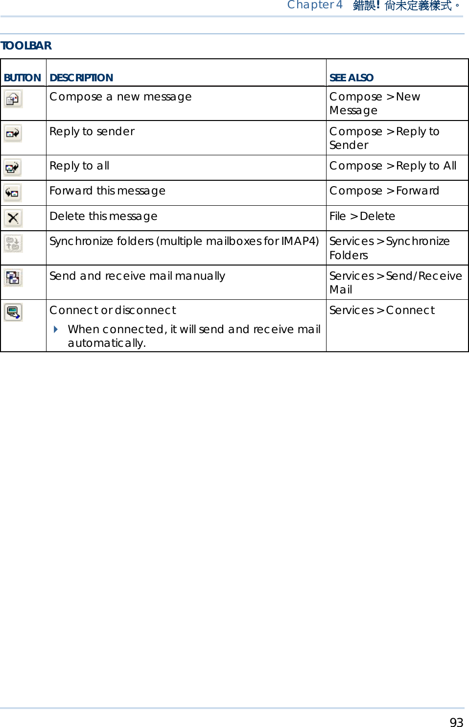
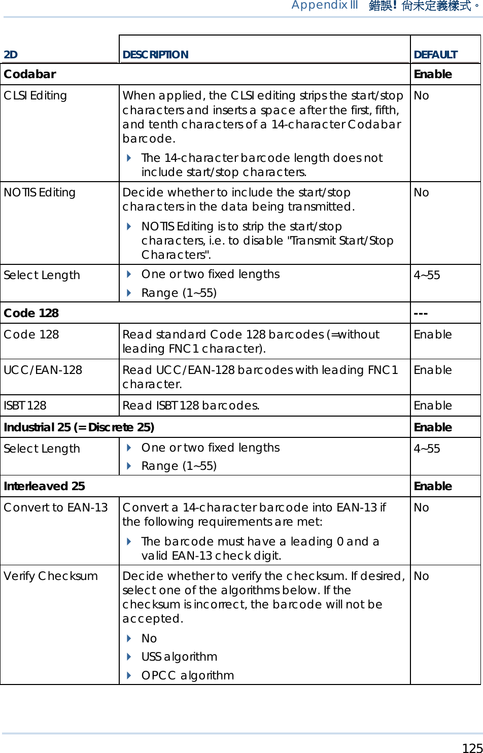
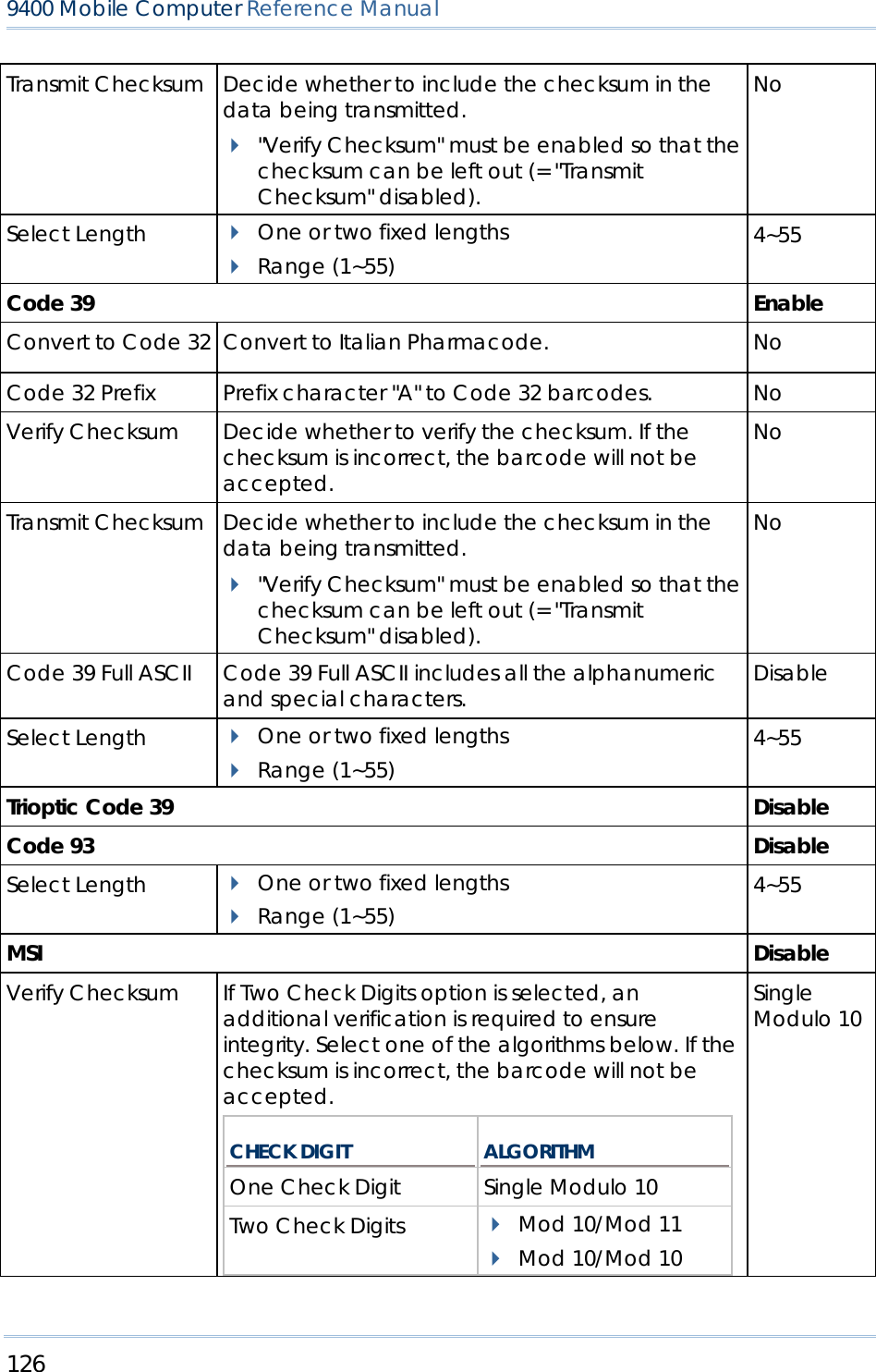
![90 9400 Mobile Computer Reference Manual Display Code Length Select the check box to display the code length after decoding a barcode. Disabled Display RFID UID Select the check box to display UID after decoding an RFID tag. Enabled Display RFID User Data Select the check box to display user data after decoding an RFID tag. Disabled Use Delimiter to separate UID from data Decide whether or not to use a delimiter to separate UID from user data when decoding an RFID tag. Disabled 4.3.4 BEEPER / VIBRATOR Tap the [Beeper / Vibrator] button on the General tab to configure associated settings. BEEPER / VIBRATOR DEFAULT Good Read Beep Mute, or Sound 1~9 Sound 1 Warning Beep Mute, or Sound 1~9 Sound 2 Vibration Duration 0~30 (sec.) 0 = Disable the vibrator 0 (= Disable) 4.3.5 SYMBOLOGY SETTINGS For barcode settings, tap the Symbologies tab. Refer to Appendix I – Scan Engine Settings for the symbologies or RFID tags supported by a scan engine. Refer to the Symbology Settings Table in Appendix II – CCD/Laser Scan Engine. Refer to the Symbology Settings Table in Appendix III – 2D Scan Engine. 4.4 INBOX You can send and receive e-mail by connecting to a POP3 or IMAP4 server. Inbox provides an e-mail service for each method you use. In addition, you can synchronize the e-mail messages in Inbox with either Microsoft Outlook or Microsoft Exchange Server on your computer through the default ActiveSync mail service.](https://usermanual.wiki/CipherLab/M0010A/User-Guide-915892-Page-98.png)
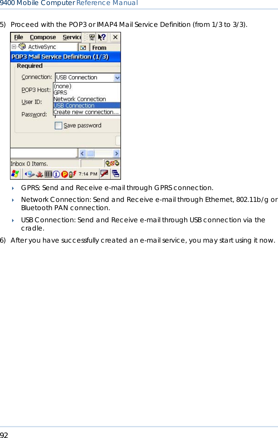
![91 Chapter 4 錯誤! 尚未定義樣式。 4.4.1 CREATING AN E-MAIL BOX 1) Go to Start > Programs > Inbox to open the Inbox application. Tap and drag the toolbar handle to move it under the menu bar. 2) Select Services > Options from the menu bar. (left below) 3) Tap and drag the dialog box to show the right edge. Tap [Add] to create an e-mail service. 4) In the Service Name dialog box, select POP3 Mail or IMAP4 Mail for the service type. (right below) Change the name of e-mail service if necessary. Tap [OK].](https://usermanual.wiki/CipherLab/M0010A/User-Guide-915892-Page-99.png)
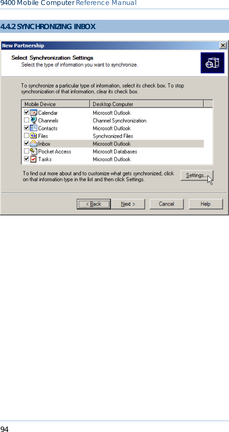
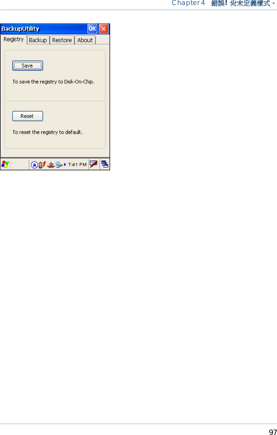
![95 Chapter 4 錯誤! 尚未定義樣式。 When you seat the mobile computer in the cradle and connect it to your computer for the first time, ActiveSync 3.7.1 will guide you through setting up a partnership between the mobile computer and your desktop computer. Refer to ActiveSync with a Computer. Select the check box of Inbox as shown above, and click [Settings] to configure it. Note: ActiveSync 4.x does not support Inbox Synchronization. We recommend that you have ActiveSync 3.7.1 installed on your computer. 4.5 BACKUP UTILITY The CipherLab Backup Utility is provided to help you easily make copies of data and restore your mobile computer's specific registry settings, install applications, user data, etc. Find out your OS version: go to Start > Settings > Control Panel and select System. Select the Device Name tab. You may use the backups (.bkp) for these purposes: Full Restore Operation Backup all necessary files here (you don't have to select "Registry") so that you can restore your mobile computer to an operational state following a disaster. Partial Restore Operation Backup a few specific files here so that you can restore small numbers of files after you have deleted them by accident or found them corrupted. Easy Cloning Backup everything (including "Registry") necessary for cloning other 9400 Mobile Computers. Now go to Start > Programs > BackupUtility to open the CipherLab Backup Utility.](https://usermanual.wiki/CipherLab/M0010A/User-Guide-915892-Page-103.png)
![96 9400 Mobile Computer Reference Manual 4.5.1 MANAGING THE REGISTRY If you are using this backup utility for the first time, you must manually save the system registry to the DiskOnChip folder first! Tap [Save] now to save the current system registry to "\DiskOnChip\Sysbak\Registry.dat". Warning: As long as you make any changes to the system configurations and settings, you must tap [Save] to update the system registry here. Otherwise, it will reload the old registry values in use after a cold boot. If you wish to reset the current system configurations and settings to defaults, tap [Reset] to delete the current system registry "\DiskOnChip\Sysbak\Registry.dat". It will then reload the default registry values after a cold boot.](https://usermanual.wiki/CipherLab/M0010A/User-Guide-915892-Page-104.png)
![98 9400 Mobile Computer Reference Manual 4.5.2 GETTING READY FOR BACKING UP FILES Tap the Backup tab and it will automatically start scanning the file system. Within a few minutes, it will generate a list for the backup operation. IF THE ITEMS "WIFI" AND "REGISTRY" ARE NOT LISTED... This means no Registry.dat and Wifi.dat are found in "\DiskOnChip\Sysbak\". Take necessary steps before you tap [Refresh] to refresh the list of available items.](https://usermanual.wiki/CipherLab/M0010A/User-Guide-915892-Page-106.png)
![99 Chapter 4 錯誤! 尚未定義樣式。 WiFi - Turn on the power to the 802.11b/g module through the Wireless Power Manager, and then select an available network to connect. Registry - Go to the Registry tab and tap [Save]. Warning: You may not be able to backup all data when programs are still running! It is suggested that you exit all the applications before backup. 4.5.3 BACKING UP FILES 1) Select the items you wish to backup, and tap [Backup]. 2) Tap if you need to save the backup to a different directory or file name (.bkp). By default, it will save the selected items to the DiskOnChip folder by the current date - the format of filename is "Backup_(4-digit year)(2-digit month)(2-digit date)". 3) Tap [Start] to pack all the selected items into one .bkp file. 4) Once the backup process is completed, tap [Report] to view the log file if necessary. 5) Tap [OK] to close the current window. Note: If you wish to backup files to this new directory or file name in future runs, you must tap on the toolbar to save the current settings and exit the application.](https://usermanual.wiki/CipherLab/M0010A/User-Guide-915892-Page-107.png)
![101 Chapter 4 錯誤! 尚未定義樣式。 FILE MANIPULATION Tap [Refresh] to refresh the list of available backups. If a backup file is not desired any more, select it and tap [Delete]. AUTO RESTORE Select a desired backup file from the list and tap [AutoRestore]. It will prefix an asterisk to the selected file, indicating the specific file will be used in the restore process that starts automatically right after a cold boot. Note: For the Auto Restore setting to take effect, you must tap on the toolbar to save the current settings and exit the application. MANUAL RESTORE Full Restore Operation 1. Select a desired backup file from the list. 2. Tap [Restore]. 3. Tap [Start] to run the restore process. 4. Once the restore process is completed, you will be asked to perform a warm boot. Tap [No] if you wish to warm boot later. You may tap [Report] to view the log file if necessary.](https://usermanual.wiki/CipherLab/M0010A/User-Guide-915892-Page-109.png)
![102 9400 Mobile Computer Reference Manual Partial Restore Operation 1. Double-tap a desired backup file from the list. 2. Select the desired items. 3. Tap [Restore]. 4. Tap [Start] to run the restore process. 5. Once the restore process is completed, you will be asked to perform a warm boot. Tap [No] if you wish to warm boot later. You may tap [Report] to view the log file if necessary. Warning: You must perform a warm boot after the restore operation!](https://usermanual.wiki/CipherLab/M0010A/User-Guide-915892-Page-110.png)
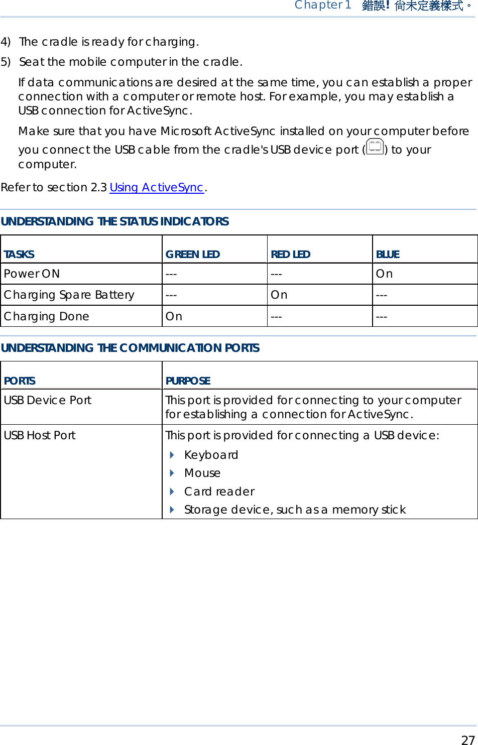
![103 Chapter 4 錯誤! 尚未定義樣式。 4.6 BUTTON ASSIGNMENT UTILITY The CipherLab Button Assignment Utility allows the following keys to be re-defined as another key or to serve as a shortcut key for launching a specific program. P1 and P2 on the keypad (Programmable key 1 & key 2) SCAN key on the keypad Side triggers on each side of the touch screen – Left-Up, Left-Down, Right-Up, and Right-Down keys Note: By default, the four side triggers are programmed to serve as ENTER keys (upper ones) as well as SCAN keys (lower ones). Now go to Start > Programs > Buttons to open the CipherLab Button Assignment Utility. 1) Tap the label of one of these seven keys. For example, tap [Left Up] to configure the upper-left side trigger.](https://usermanual.wiki/CipherLab/M0010A/User-Guide-915892-Page-111.png)
![104 9400 Mobile Computer Reference Manual 2) You may assign one of the following key values to the upper-left side trigger or have it serve as a shortcut key to launch a specific program. Enter Scan Esc Delete Backspace Space Tab F1 ~ F12 3) Tap [OK] for the change to take effect. 4) Tap on the toolbar to save the current settings and exit the application.](https://usermanual.wiki/CipherLab/M0010A/User-Guide-915892-Page-112.png)

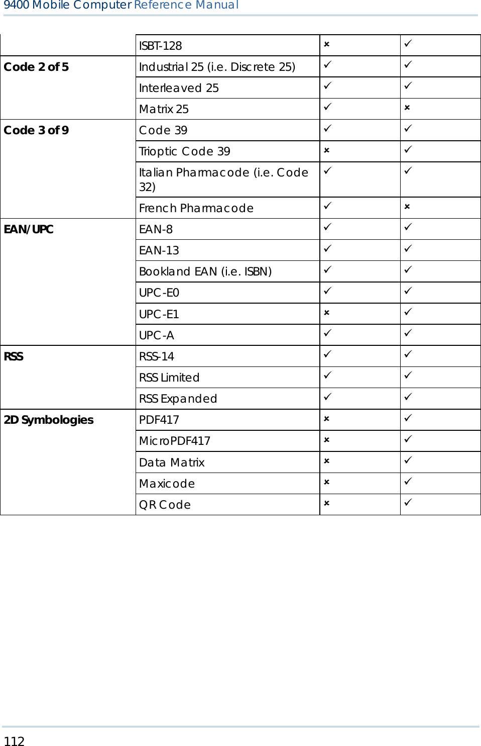
![111 The Reader Configuration Utility (94ReaderCfg.exe) allows configuring the following reader types, depending on the module equipped on your mobile computer: 1D CCD scan engine 1D Laser scan engine 2D scan engine RFID reader Options of different reader combination are allowed, such as 1D+RFID and 2D+RFID. For each combination, both readers can be initialized and ready for scanning at the same time (dual mode operation). For example, if you press the [Scan] button while running the 94ReaderCfg applet on the mobile computer, it will read a barcode in position or an RFID tag in proximity depending on which one comes first. Note: You cannot have 1D+2D scan engines installed on the mobile computer because they are both barcode readers! SYMBOLOGIES SUPPORTED Varying by the scan engine installed, the supported symbologies or tag types are listed below. For details on configuring associated settings, please refer to each Appendix separately. CCD, LASER 2D Codabar 9 9 Code 11 8 9 Code 93 9 9 Composite Code 8 9 MSI 9 9 Plessey 9 8 Postal Codes 8 9 Telepen 9 8 Code 128 Code 128 9 9 EAN-128 9 9 Appendix I SCAN ENGINE SETTINGS](https://usermanual.wiki/CipherLab/M0010A/User-Guide-915892-Page-119.png)

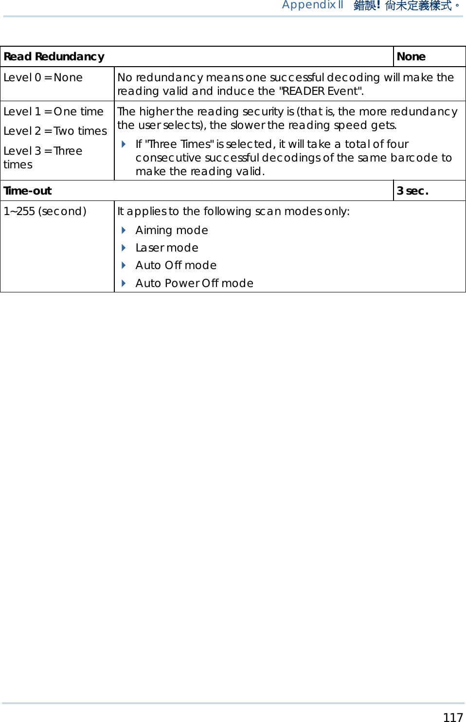
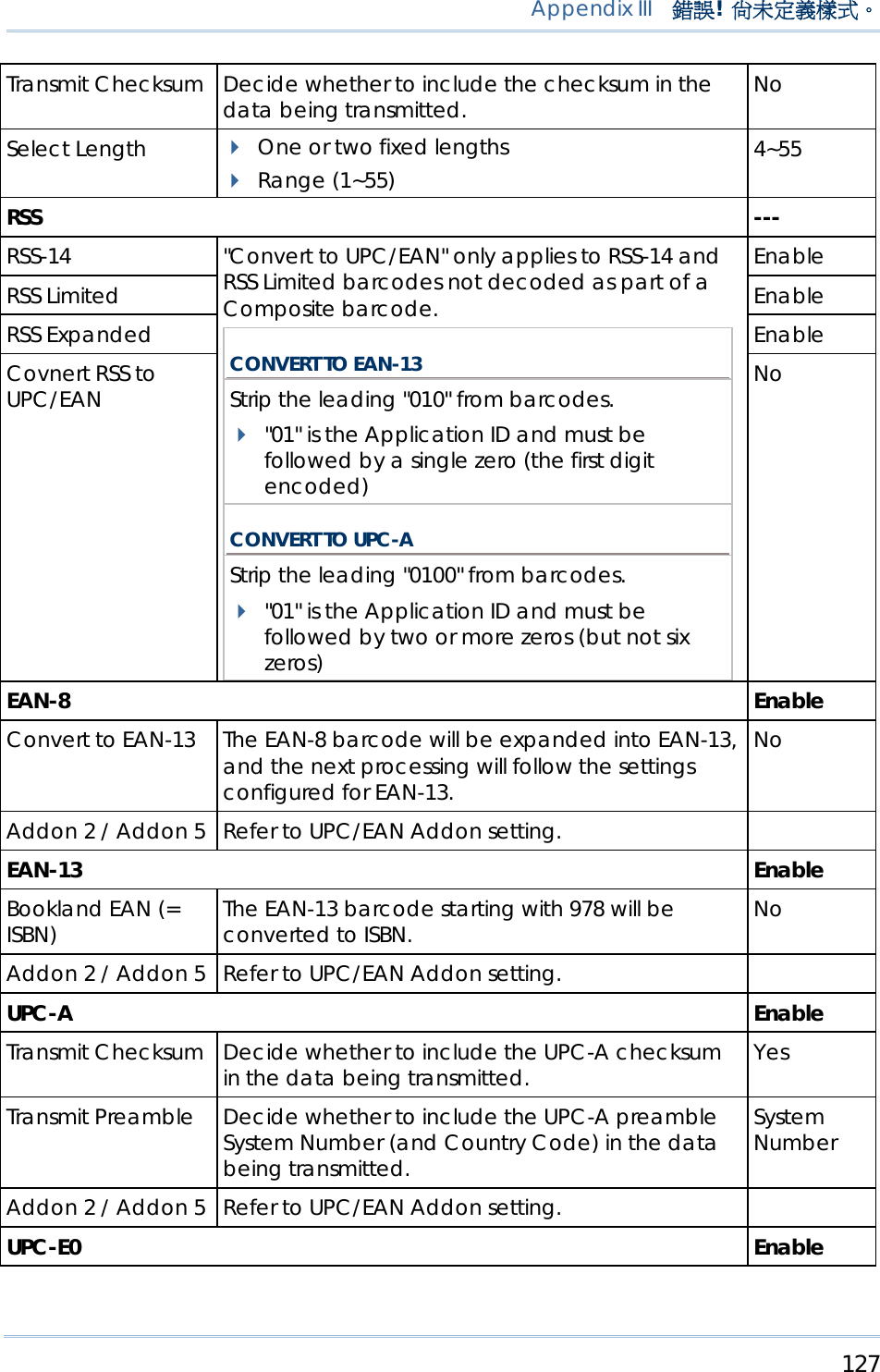
![118 9400 Mobile Computer Reference Manual SYMBOLOGY SETTINGS TABLE CCD/LASER DESCRIPTION DEFAULT Codabar Enable Select Start/Stop Characters If "Transmit Start/Stop Characters" is desired, select one set: abcd / abcd abcd / tn*e ABCD / ABCD ABCD / TN*E abcd / abcd Transmit Start/Stop Characters Decide whether to include the start/stop characters in the data being transmitted. No Code 128 / EAN-128 Enable Transmit Code ID (for EAN-128) Decide whether to include Code ID (“]C1”) will be included in the data being transmitted. No Industrial 25 (= Discrete 25) Enable Start/Stop Selection This decides the readability of all 2 of 5 symbology variants. For example, flight tickets actually use an Industrial 2 of 5 barcode but with Interleaved 2 of 5 start/stop pattern. In order to read this barcode, the start/stop pattern selection parameter of Industrial 2 of 5 should set to "Interleaved 25". Industrial 25 Verify Checksum Decide whether to verify the checksum. If the checksum is incorrect, the barcode will not be accepted. No](https://usermanual.wiki/CipherLab/M0010A/User-Guide-915892-Page-126.png)
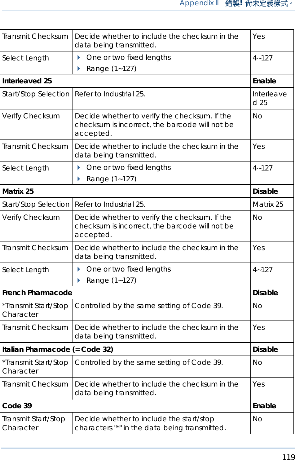
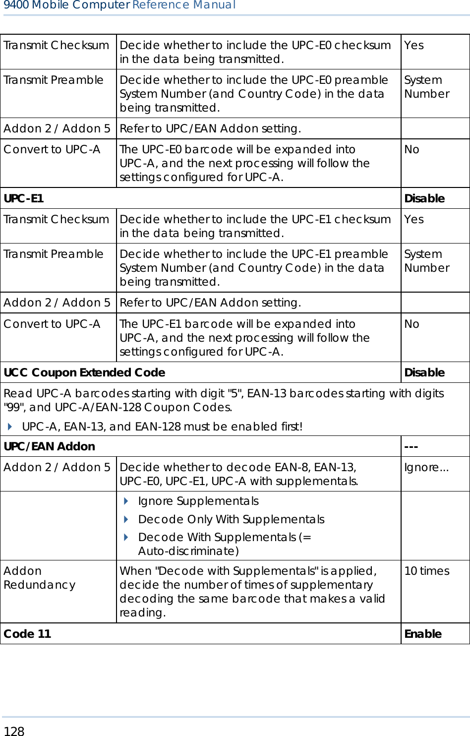
![120 9400 Mobile Computer Reference Manual Verify Checksum Decide whether to verify the checksum. If the checksum is incorrect, the barcode will not be accepted. No Transmit Checksum Decide whether to include the checksum in the data being transmitted. Yes Code 39 Full ASCII Code 39 Full ASCII includes all the alphanumeric and special characters. Disable Code 93 Enable MSI Disable Verify Checksum Select one of the three calculation formulas to verify the checksum. If the checksum is incorrect, the barcode will not be accepted. Single Modulo 10 Double Modulo 10 Modulo 11 & 10 Single Modulo 10 Transmit Checksum Decide whether to include the checksum in the data being transmitted. Last digit not transmitted Both digits transmitted Both digits not transmitted Both digits transmitted Select Length One or two fixed lengths Range (1~127) 4~127 Negative Barcode Disable Plessey Disable Convert to UK Plessey When applied, each occurrence of the character "A" in the barcode data will be replaced by the character "X". No Transmit Checksum Decide whether to include the checksum (2 digits) in the data being transmitted. Yes Telepen Disable Original Telepen (Numeric) The original Telepen includes numeric characters. Yes AIM Telepen (Full ASCII) AIM Telepen (Full ASCII) includes all the alphanumeric and special characters. No RSS-14 Disable Transmit Code ID Decide whether to include Code ID ("]e0") will be included in the data being transmitted. Yes](https://usermanual.wiki/CipherLab/M0010A/User-Guide-915892-Page-128.png)
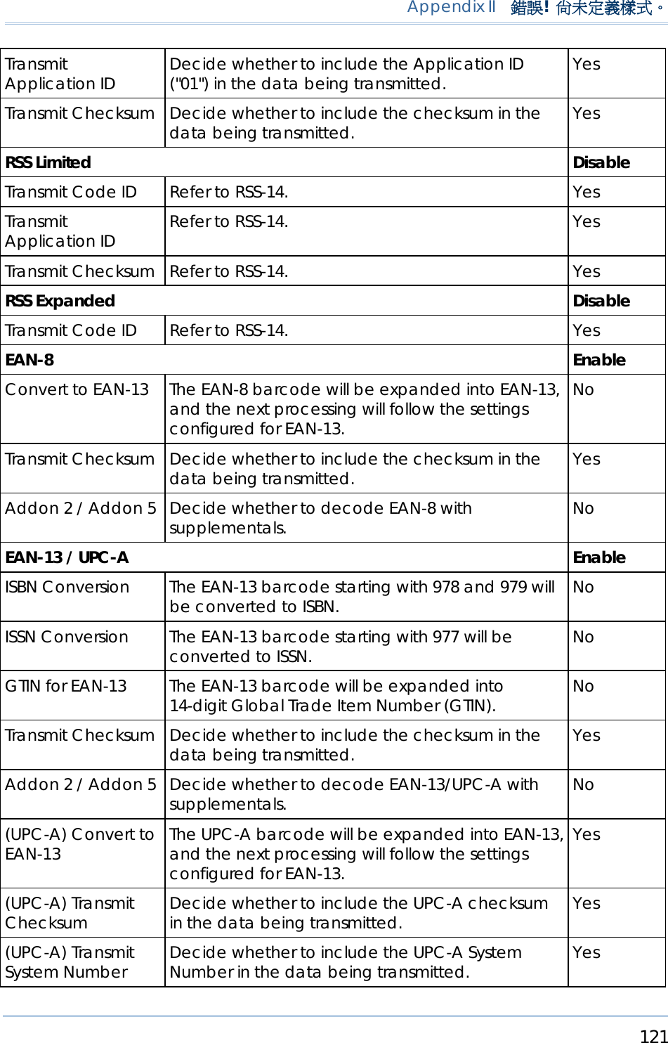
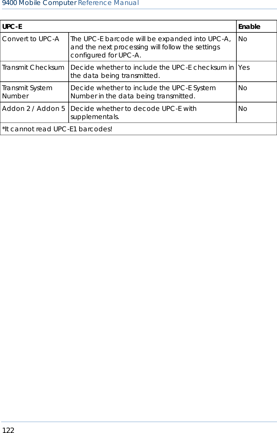
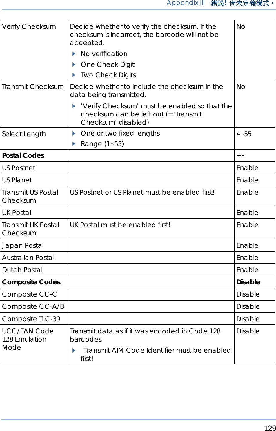
![130 9400 Mobile Computer Reference Manual UPC Composite Mode UPC barcodes can be "linked" with a 2D barcode during transmission as if they were one barcode. UPC NEVER LINKED Transmit UPC barcodes regardless of whether a 2D barcode is detected. UPC ALWAYS LINKED Transmit UPC barcodes and the 2D portion. UPC Always Linked If the 2D portion is not detected, the UPC barcode will not be transmitted. CC-A/B or CC-C must be enabled! AUTO-DISCRIMINATE UPC COMPOSITES Transmit UPC barcodes as well as the 2D portion if present. 2D Symbologies --- PDF417 Enable MicroPDF417 Disable MicroPDF417 Code 128 Emulation Transmit data from certain MicroPDF417 barcodes as if it was encoded in Code 128 barcodes. Transmit AIM Code Identifier must be enabled first! When applied, the MicroPDF417 barcodes are transmitted with one of these prefixes: THE FIRST CODEWORD OF MICROPDF417 IS 903-907, 912, 914, 915: The original Code ID "]L3" will be changed to "]C1". THE FIRST CODEWORD OF MICROPDF417 IS 908 OR 909: The original Code ID "]L4" will be changed to "]C2". THE FIRST CODEWORD OF MICROPDF417 IS 910 OR 911: The original Code ID "]L5" will be changed to "]C0". Disable](https://usermanual.wiki/CipherLab/M0010A/User-Guide-915892-Page-138.png)