Cisco Linksys WAP54A 54Mbps Wireless Access Point User Manual WAP54A AP v1 3
Cisco-Linksys, LLC 54Mbps Wireless Access Point WAP54A AP v1 3
Manual

1
WAP54A
54Mbps Wireless Network AP
User’s Manual
Draft v. 1.3
2
Table of Contents
1. INTRODUCTION 3
1.1 SCOPE 3
1.2 OBJECTIVE 3
1.3 INTENDED AUDIENCE 3
1.4 FEATURES 3
1.5 PACKAGE CONTENTS 3
1.6 SYSTEM REQUIREMENTS 3
2. GETTING TO KNOW THE ATHEROS ACCESS POINT 4
2.1 FRONT VIEW 4
2.2 REAR VIEW 5
3. Network Attachment and Configuration of the Access Point 7
3.1.1 CONFIGURING THE AP 7
3.1.2 WEB BROWSER 7
3.1.3 GENERAL CONFIGURATION PAGE 9
3.1.4 GENERAL ADVANCED CONFIGURATION PAGE 12
3.1.5 SHARED KEY CONFIGURATON 14
3
1 Introduction
1.1 Scope
The intent of this document is to familiarize you with the Access Point, its physical characteristics, setup,
configuration, and usage.
1.2 Objectives
After reading this user’s guide, you should be able to install, configure, control, and maintain the Access Point.
1.3 Intended Audience
The intended audience for this user‘s guide is evaluators of AP products. The reader is assumed to have conceptual
and practical knowledge about AP concepts, features, and functions. This guide relies on the reader’s familiarity with
APs in general, while discussing the specific characteristics of the AP.
1.4 Features
AP implements an IEEE 802.11a wireless LAN (WLAN) AP or data-oriented Residential Gateway (RG) on a single
PCB. The AP provides an IEEE 802.11a Access Point supporting up to 60 IEEE 802.11a station associations
including the AP itself. Rates of 6 to 54 Mbps are supported in standard IEEE 802.11a mode. All transmission rates
are supported across the lower and middle bands of the 5 GHz spectrum (5.15 to 5.35 GHz).
1.5 Package Contents
The AP is provided in a completely enclosed plastic housing with two 180° swivel antennas, a power supply, and a
serial cable for use in AP software configuration. The AP Reference Design contains a single 10/100 Ethernet port.
Using this Ethernet port, a RJ-45 cable, (not provided by) should be used to connect the AP to a wired Ethernet LAN.
1.6 System Requirements
The AP Contains a small boot executive that allows the main VxWorks system software to be downloaded using the
Ethernet port over an FTP connection. The VxWorks system software can also reside in the Flash memory of the AP,
which allows booting without the need to download VxWorks form the host PC over an FTP connection. A
configuration file is created in Flash memory to store user configurable parameters such as WEP keys. A PC with an
Ethernet connection is required to perform the initial VxWorks system software loading operation as well as AP
configuration.

4
2 Getting to Know the Access Point
2.1 Front Panel
The Access Point (AP) has 3 LEDs, and a pair of side-mounted antennas that rotate 180° for alternative reception
positioning and compact packaging.
LED 3 (Wireless Link)
LED 2 (Ethernet Link)
LED 1 (Power Status)
Table 1- LED Functionality
LED 1 Description
Off No Power
On Power On and Ready for Operation
Blink Power On but Not Ready for Operation – at initial power on or reset, this
indicates self-test or software loading; at other times, this indicates a system
fault

5
LED2 Description
Off No Ethernet Link Detected
Green On 100 Mbps Link Detected but No Activity
Green Blink 100 Mbps Link Activity – blink rate is proportional to activity
Amber On 10 Mbps Link Detected but No Activity
Amber Blink 10 Mbps Link Activity – blink rate is proportional to activity
LED 3 Description
Off Wireless Link Disabled
Very Slow Blink Looking for Network Association
Slow Blink Associated with Network but No Activity
Fast Blink Associated with Network – blink rate is proportional to activity
2.2 Rear Panel
The rear panel of the AP has a RJ-45 Ethernet jack, a reset button, and a power supply connector,
Power Supply Connector
Reset Button
RJ-45 Ethernet Jack
6
z The RJ-45 Ethernet jack is provided for 10/100 Mbps connectivity to a wired Ethernet LAN. The Ethernet
subsystem is based on a single chip 10/100 Mbps integrated PCI Ethernet Media Access Controller (MAC) +
PHY (DP83815) from National Semiconductor Corporation.
z An on-board MAX6713 reset circuit provides reset to processor, memory, and PCI devices. A manual push-
button reset option provides easy generation of the reset signal without cycling power to the AP. A 5V power
supply is provided to power the AP.
z A 5V power supply is provided and is plugged into the power supply connector of the AP.
7
3. Network Attachment and Configuration of the Access Point
3.1.1 Configuring the AP
When the VxWorks system software is loaded, the AP has to be configured to set some options such as the channel
frequency and Service Set Identifier (SSID). This can be done through a web browser with access to the built-in AP
web server.
3.1.2 Web Browser
The following procedures show the steps to configure the channel frequency and SSID using a web browser:
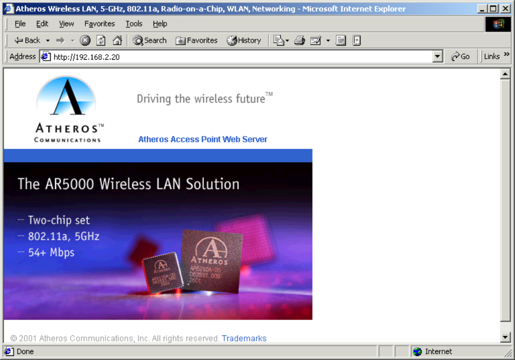
1. Launch a web browser (Netscape Navigator or Internet Explorer are examples of commonly used web
browsers) from the Host PC or other PC with IP address 192.168.2.10, and subnet address as 255.255.0.0,
and enter the IP address that is assigned to the AP as the URL, for example http://192.168.2.20 .
8
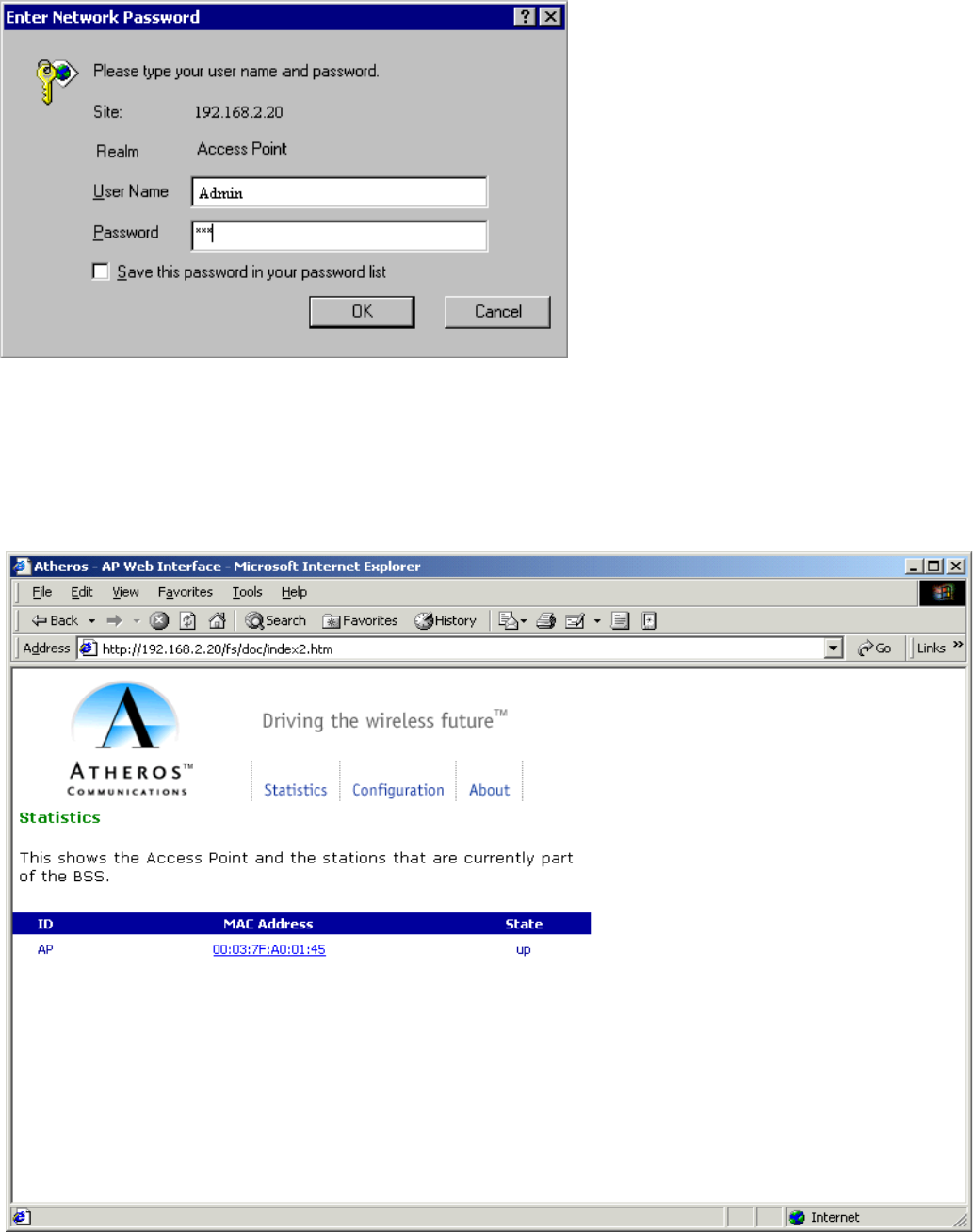
2. Select the Web Server hotlink. A dialog box will appear to request login authorization.
3. Enter the information as follow:
Log in: Admin (case sensitive)
Password: 5up
Click OK to complete the login process. The Access Point Statistic web page appear.
9
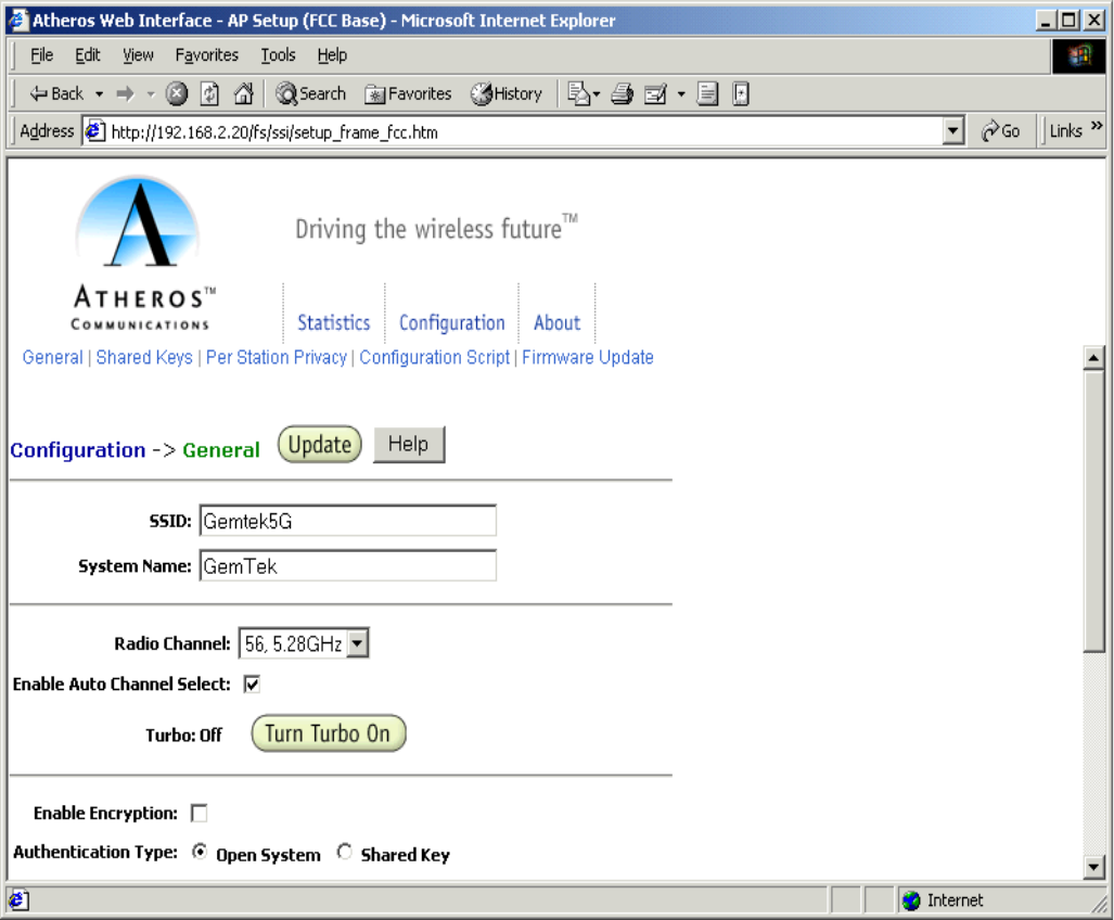
3.1.3 General Configuration Page
1. Click on the Configuration hotlink to enter the wireless setting page.

10
2. The summarizes of the General Configuration data fields of the AP.
SSID Identification of the AP. Enter a number or
address between 1 and 32 characters in
length that the STAs are associating with in
Infrastructure mode. You can specify more
than one AP in an SSID. Use the System
Name field to uniquely identify each AP.
System Name Specifies a unique name for AP. Enter a
unique text string of up to 32 characters in
length.
Radio Channel Select the desired frequency of operation
from the drop-down menu.
The radio frequencies that appear in the
Radio Channel drop-down menu are
dependent on the Regulatory Domain set
specified.
Enable Auto Channel Select Select the checkbox to automatically search
through the frequency list to find an unused
channel.
If a radio frequency is specified in the
Radio Channel field and the Auto Channel
Select is enabled. The designated frequency
in the Radio Channel field will be the first
frequency auto-attempted before scanning
the remaining list.
Turbo Mode Allows transmission on two channels
thereby improving data rate.
To enable/disable Turbo Mode, click on the
appropriate Turbo button.
Enable Encryption Enables Wired Equivalent Privacy on the
AP
Authentication Type Specifies the authentication type used.
“Open” specifies no authentication. A STA
must be authenticated before it can be
associated to an AP.
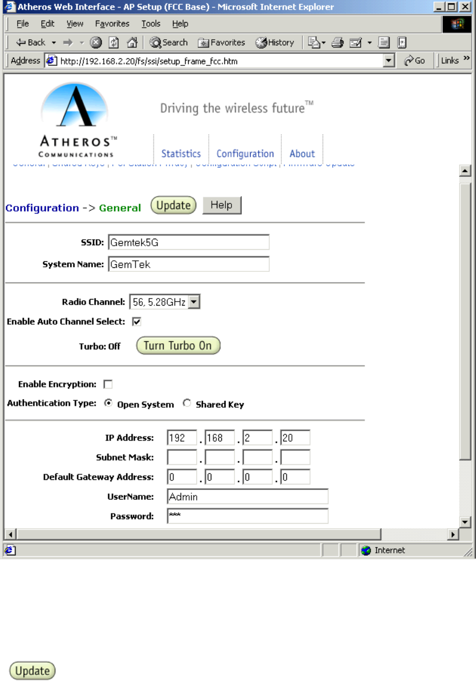
IP Address Specifies the IP address of the AP.
Subnet Mask Specifies the subnet mask for the AP
3. Enter SSID for example “Gemtek5G”, The SSID name must not exceed 32 characters.
4. Select one of the Radio Channel from range 5.18GHz to 5.32GHz. This value specify the stations under AP’s
associated in Infrastructure mode.
11
4 Click on the Update button to commit to the system.
12
5 After clicked the Update button, you have to apply the REBOOT AP button to effect the setting and reboot the
AP.
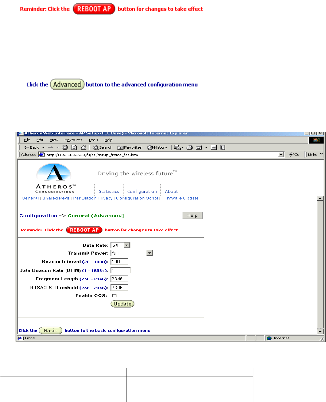
3.1.4 General Advanced Configuration Page
1. Click on the Advanced button from the left end of the Configuration page.
2. The Advanced Configuration Page will appear. It allow you to enter advanced information of the AP.
3. The summarizes data field :
Advanced Configuration Field Description
Data Rate Specifies rate of data transmission. Select
the desired rate from the drop-down menu.
The Best selection will adapt the rate to

13
the best available.
Transmit Power Specifies the level of transmit power.
Specify the value of the transmit power
from the drop-down menu.
Decrease the transmit power if more than
one AP is co-located using the same
channel frequency.
Beacon Interval Specified the Beacon Interval value. Enter
a value between 20 and 1000.
Data Beacon Rate Specifies the Data Beacon Rate. Enter a
value between 1 and 16384 that specifies
the Delivery Traffic Indication Message
(DTIM).
Fragment Length Specifies the fragment length. Enter a
value between 256 and 2346.
RTS/CTS Threshold Specifies the value of the RTS/CTS
threshold.
Enter a value between 256 and 2346.
Enable QOS Use the checkbox to allow the AP to
participate in a QOS environment.
4. Click on the Update button to commit to the system.
5. After clicked the Update button, you have to apply the REBOOT AP button to effect the setting and reboot the
AP.
3.1.5 Shared Key Configuration
1. Click on the Shared Keys tab highlight with the black circle.
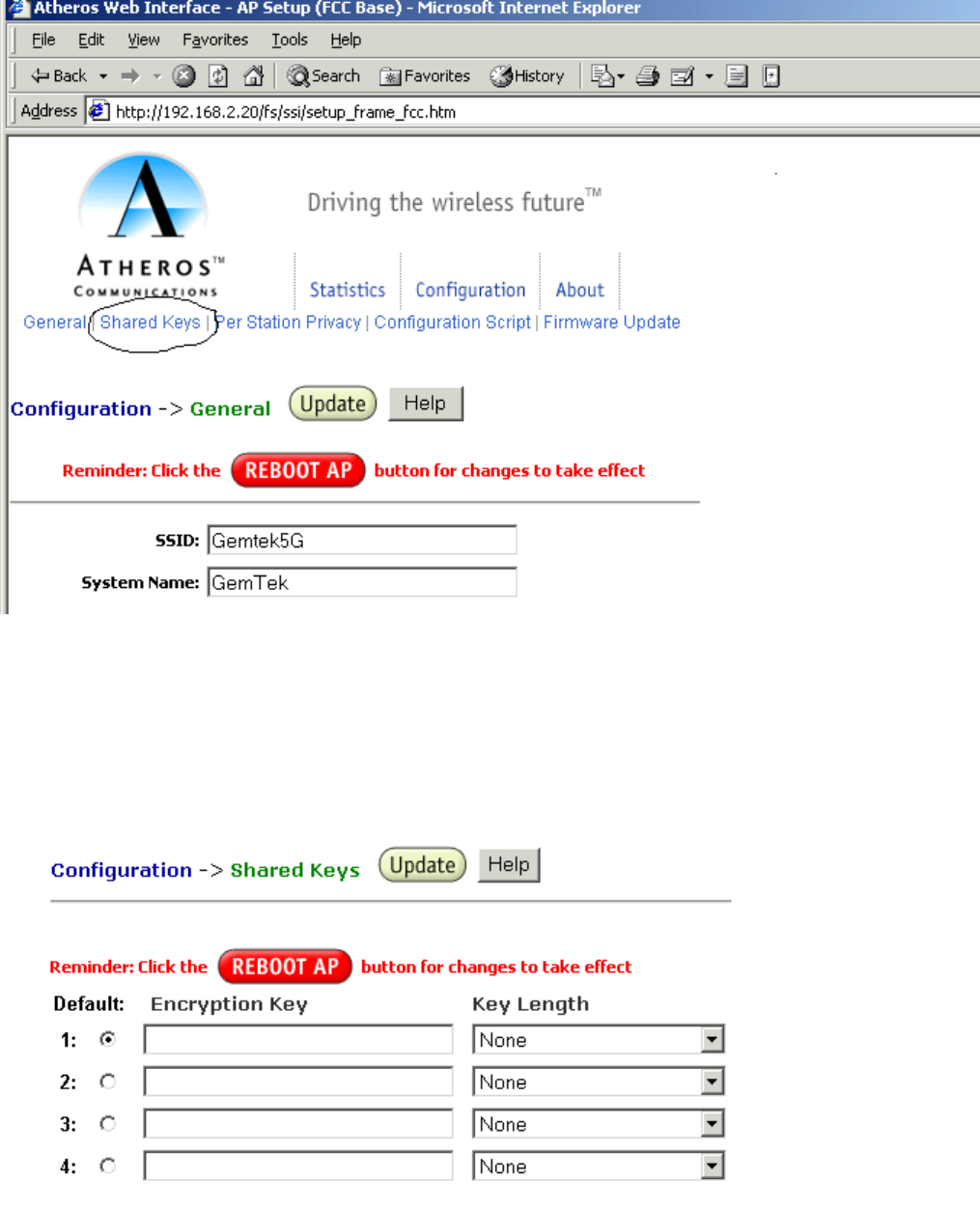
14
2. The Shared Keys Configuration allow you to:
~ Select default shared key encryption keys
~ Specify the key length
~ Specify the shared WEP’s keys
3. Click on the Update button to commit to the system.

15
4. After clicked the Update button, you have to apply the REBOOT AP button to effects the setting and reboot
the AP.
5. The Wired Equivalent Privacy Settings.
WEP: Disable WEP is disabled. Any STA can
access to the network
WEP: Enable
ACLShared key
ACL MAC
address
Key Map Permission
WEP
No Disable No No No WEP is disabled. Any STA can
access to the network
Yes Disable No No No Only STA with matched shared
key can access to the network
Yes Enable Yes No Allow 1. STA with matched MAC ID
can access to the network
2. Any STAs with matched
shared key are also allowed
to access to the network
Yes Enable No Unique
key
Allow 1. STA with matched unique key
can access to the network
2. Any STAs with matched
shared key are also allowed
to access to the network
Yes Enable Yes Unique
key
Allow 1. STA with matched MAC ID
and matched unique key can
access to the network
2. Any STAs with matched
shared key are also allowed
to access to the network
X Enable Yes No Deny STA with the matched MAC ID is
blocked from accessing the
network
X Enable No Unique
key
Deny STA with the matched unique
key is blocked from accessing
the network
X Enable Yes Unique
key
Deny STA with the matched MAC ID
and unique key is blocked from
accessing the network
Yes Strict x x x 1. Only STA with MAC ID and/or
unique key matched to the
setup in ACL can access to
the network.
2
. The STAs with only shared
key are blocked from
accessing the network.
16
Federal Communication Commission Interference Statement
This equipment has been tested and found to comply with the limits for a Class B digital device,
pursuant to Part 15 of the FCC Rules. These limits are designed to provide reasonable protection
against harmful interference in a residential installation. This equipment generates, uses and can
radiate radio frequency energy and, if not installed and used in accordance with the instructions,
may cause harmful interference to radio communications. However, there is no guarantee that
interference will not occur in a particular installation. If this equipment does cause harmful
interference to radio or television reception, which can be determined by turning the equipment
off and on, the user is encouraged to try to correct the interference by one of the following
measures:
- Reorient or relocate the receiving antenna.
- Increase the separation between the equipment and receiver.
- Connect the equipment into an outlet on a circuit different from that to which the receiver is
connected.
- Consult the dealer or an experienced radio/TV technician for help.
FCC Caution: To assure continued compliance, (example - use only shielded interface cables
when connecting to computer or peripheral devices) any changes or modifications not expressly
approved by the party responsible for compliance could void the user's authority to operate this
equipment.
This device complies with Part 15 of the FCC Rules. Operation is subject to the following two
conditions: (1) This device may not cause harmful interference, and (2) this device must accept
any interference received, including interference that may cause undesired operation.
IMPORTANT NOTE:
FCC Radiation Exposure Statement:
This equipment complies with FCC radiation exposure limits set forth for an uncontrolled
environment. This equipment should be installed and operated with minimum distance 20cm
between the radiator & your body.
This transmitter must not be co-located or operating in conjunction with any other antenna or
transmitter.
17