Cisco Linksys WM11 PCMCIA Radio Card User Manual WLAN Module Manual
Cisco-Linksys, LLC PCMCIA Radio Card WLAN Module Manual
Contents
- 1. DoC Statement
- 2. Users Manual
Users Manual
11Mbps Wireless LAN Module
User Manual
Rev 0.9
Regulatory Compliance
FCC Interference Statement
This equipment has been tested and found to comply with the limits for a Class B digital device, pursuant to part 15
of the FCC Rules. These limits are designed to provide reasonable protection against harmful interference in a resi-
dential installation. This equipment generates, uses and can radiate radio frequency energy and, if not installed and
used in accordance with the instructions, may cause harmful interference to radio communications. However, there
is no guarantee that interference will not occur in a particular installation. If this equipment does cause harmful in-
terference to radio or television reception, which can be determined by turning the equipment off and on, the user is
encouraged to try to correct the interference by one or more of the following measures:
y Reorient or relocate the receiving antenna.
y Increase the separation between the equipment and receiver.
y Connect the equipment into an outlet on a circuit different from that to which the receiver is connected.
y Consult the dealer or an experienced radio/TV technician for help.
You are cautioned that changes or modifications not expressly approved by the party responsible for compli-
ance could void your authority to operate the equipment.
IMPORTANT NOTE:
This equipment complies with FCC radiation exposure limits set forth for an uncontrolled environment. In order to
avoid the possibility of exceeding the FCC radio frequency exposure limits, human proximity to the antenna shall not
be less than 20cm (8 inches) during normal operation.
This transmitter must not be co-located or operation in conjunction with any other antenna or transmitter
This device is intended only for OEM integrators under the following conditions:
1) The antenna must be installed such that 20 cm is maintained between the antenna and users, and
2) The transmitter module may not be co-located with any other transmitter or antenna.
As long as 2 conditions above are met, further transmitter test will not be required. However, the OEM integrator is
still responsible for testing their end-product for any additional compliance requirements required with this module
installed (for example, digital device emissions, PC peripheral requirements, etc.).
IMPORTANT NOTE: In the event that these conditions can not be met (for example certain laptop configurations or
co-location with another transmitter), then the FCC authorization is no longer considered valid and the FCC ID can
not be used on the final product. In these circumstances, the OEM integrator will be responsible for re-evaluating the
end product (including the transmitter) and obtaining a separate FCC authorization.
End Product Labeling
This transmitter module is authorized only for use in device where the antenna may be installed such that 20 cm may
be maintained between the antenna and users (for example access points, routers, wireless ADSL modems, and
similar equipment). The final end product must be labeled in a visible area with the following: “Contains TX FCC ID:
PKW-WM11”.
Manual Information That Must be Included
The users manual for end users must include the following information in a prominent location “ IMPORTANT NOTE:
To comply with FCC RF exposure compliance requirements, the antenna used for this transmitter must be installed
to provide a separation distance of at least 20 cm from all persons and must not be co-located or operating in
conjunction with any other antenna or transmitter.

Wireless LAN card user manual
ii
Table of contents
CHAPTER 1 .................................................................................................... 1
Introduction 1
Features ............................................................................................... 1
What is Wireless LAN? ........................................................................ 1
LAN Modes .......................................................................................... 2
Notes on wireless LAN configuration .................................................. 2
CHAPTER 2 .................................................................................................... 3
Hardware installation 3
Hardware description .......................................................................... 3
Status LEDs.......................................................................................... 3
CHAPTER 3 .................................................................................................... 3
Installation for Embedded Linux System 3
Iinstallation for Linux .......................................................................... 3
CHAPTER 4 .................................................................................................... 6
Using the Wireless Utility 6
Configuration Utility............................................................................ 6
APPENDIX A .................................................................................................. 8
Troubleshooting 8
Q&A .................................................................................................... 8
APPENDIX B .................................................................................................. 9
Specifications ....................................................................................... 9

1
Chapter 1
Introduction
Thank you for using the Wireless LAN module. This high-speed Wireless LAN module provides you with an inno-
vative wireless networking solution for your embedded system. The module is easy to set up and use. With this
innovative wireless technology, you can share files and printers on the network—without inconvenient wires! Now
you can carry the LAN in your pocket!
This module is designed for
1. Wireless LAN Printer Server
2. Wireless LAN Ethernet Adapter
3. Wireless LAN Access Point / Gateway
4. Wireless LAN Router
5. Wireless LAN Broadband Router
6. Wireless LAN Presentation Gateway
Features
• Wire-free access to networked resources from anywhere beyond the desktop
• Low interference & high susceptibility guarantee reliable performance
• Delivers data rate up to 11 Mbps
• Dynamically shifts between 11, 5.5, 2, and 1 Mbps network speed, based on signal strength, for maximum avail-
ability and reliability of connection
• Uses 2.4GHz frequency band, which complies with worldwide requirement
• Used on embedded operating systems
• Ensures great security by providing the Wired Equivalent Privacy (WEP) defined in the IEEE 802.11 standard
What is Wireless LAN?
Wireless Local Area Network (WLAN) systems offer a great number of advantages over traditional wired sys-
tems. WLANs are flexible and easy to setup and manage. They are also more economical than wired LAN
systems.
Using radio frequency (RF) technology, WLANs transmit and receive data through the air. WLANs combine
data connectivity with user mobility. For example, users can roam from a conference room to their office
without being disconnected from the LAN.
Using WLANs, users can conveniently access shared information, and network administrators can configure
and augment networks without installing or moving network cables.
WLAN technology provides users with many convenient and cost saving features:
• Mobility: WLANs provide LAN users with access to real-time information anywhere in their organiza-
tion, providing service opportunities that are impossible with wired networks.
• Ease of Installation: Installing is easy for novice and expert users alike, eliminating the need to install
network cables in walls and ceilings.
• Scalability: WLANs can be configured in a variety of topologies to adapt to specific applications and
installations. Configurations are easily changed and range from peer-to-peer networks suitable for a
small number of users to full infrastructure networks of thousands of users roaming over a broad area.

Wireless LAN card user manual
2
LAN Modes
Wireless LANs can be configured in one of two ways:
Ad-hoc
Networking
Also known as a peer-to-peer network, an ad-hoc net-
work is one that allows all workstations and computers
in the network to act as servers to all other users on the
network. Users on the network can share files, print to
a shared printer, and access the Internet with a shared
modem. However, with ad-hoc networking, users can
only communicate with other wireless LAN computers
that are in the wireless LAN workgroup, and are within
range.
Infrastructure
Networking
Infrastructure networking differs from ad-hoc network-
ing in that it includes an access point. Unlike the ad-
hoc structure where users on the LAN contend the
shared bandwidth, on an infrastructure network the
access point can manage the bandwidth to maximize
bandwidth utilization.
Additionally, the access point enables users on a wire-
less LAN to access an existing wired network, allowing
wireless users to take advantage of the wired networks
resources, such as Internet, email, file transfer, and
printer sharing.
Infrastructure networking has the following advantages
over ad-hoc networking:
• Extended range: each wireless LAN computer
within the range of the access point can commu-
nicate with other wireless LAN computers within
range of the access point.
• Roaming: the access point enables a wireless
LAN computer to move through a building and still
be connected to the LAN.
• Wired to wireless LAN connectivity: the access
point bridges the gap between wireless LANs and
their wired counterparts.
Notes on wireless LAN configuration
When configuring a wireless LAN (WLAN), be sure to note the following points:
• Optimize the performance of the WLAN by ensuring that the distance between access points is not too
far. In most buildings, WLAN cards operate within a range of 100 ~ 300 feet, depending on the thick-
ness and structure of the walls.
• Radio waves can pass through walls and glass but not metal. If there is interference in transmitting
through a wall, it may be that the wall has reinforcing metal in its structure. Install another access point
to circumvent this problem.
• Floors usually have metal girders and metal reinforcing struts that interfere with WLAN transmission.

3
Chapter 2
Hardware installation
This chapter covers how to installing the wireless LAN module in your embedded system.
Hardware description
The Wireless LAN Module has a standard PCMCIA 68-pin connector for attaching to the PCMCIA port of em-
bedded system.
And this module has MMCX connector to connect to external antenna.
Status LEDs
The following table describes the meaning of the LEDs:
LED MEANING
PWR Indicates that the Card is powered on.
LINK Indicates link status. It is normally blinking. When blink-
ing, indicates that the card is scanning the channels, and
the link is not active. When lit, indicates that the card is
locked to a channel, and the link is active.
Chapter 3
Installation for Embedded Linux System
Following is a example to install the module to a embedded Linux system.
installation for Linux
Follow the steps below to install the Wireless LAN card drivers (wlan-ng v0.1.6) for Linux.
Before Installing the Linux Drivers
Before you install the Linux wlan-ng v0.1.6 drivers, you need the PCMCIA module source code. If you do not
have the source code, you can get it from the following URL:
ftp://hyper.stanford.edu/pub/pcmcia
After you have rebuilt and installed the PCMCIA module, edit /etc/pcmcia/network.opts to enable DHCP. In the
DHCP setup, you can leave the fields empty. If there is no DHCP server on your network, you might have to
disable DHCP to use a static IP and then fill the fields in /etc/pcmcia/network.opts.
In Linux there is an 802.11b Access Point with which the station can be associated.

Wireless LAN card user manual
4
Installation Procedure
1. Unpack the tgz file by typing the following line at the shell prompt, (assuming the shell prompt is >).
>gzip -cd wlan-ng-0.1.6.tgz | tar xvf -
2. Configure and install wlan v0.1.6. Be sure to configure the build as Station (STA)—do not choose Ac-
cess Point (AP) because there is no firmware available that supports the AP function.
>cd wlan-ng-0.1.6
>make config
>make all
>make install
3. Edit /etc/pcmcia/wlan-ng.conf by adding the following lines to the bottom of the file.
card "PCMCIA 11M WLAN"
manfid 0x0274, 0x1601
bind "prism2_cs"
4. Edit /etc/pcmcia/wlan-ng.opts. The fields to edit are listed below:
dot11DesireSSID
APSSID
APCHANNEL
5. Restart your computer.
>shutdown -r now

—Installation for Embedded Linux System
5
When Linux is booting up, you will hear two high pitch beeps. This means that the driver has been loaded suc-
cessfully. If you want to know if the card has connected to an access point, see if the red ACT LED on the card
is illuminated. When the ACT LED stops blinking, it means the card/station has been connected to an access
point.
6
Chapter 4
Using the Wireless Utility
This module also come with a wireless utility, following describe how to use the utility.
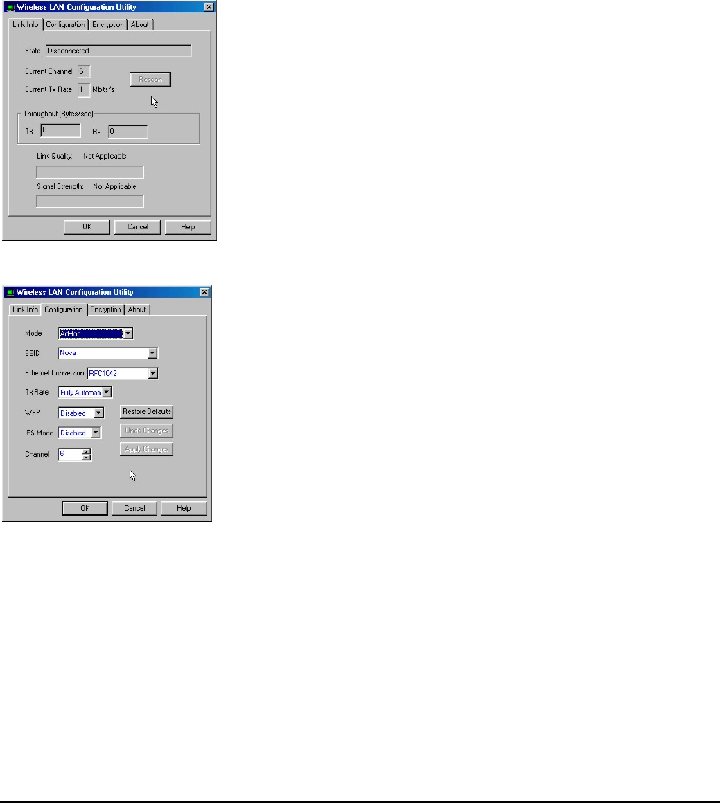
Configuration Utility
The following table describes the configuration utility:
State: displays the connection status.
Current Channel: displays the chan-
nel.
Current Tx Rate: displays the wire-
less bandwidth in megabits per
second.
Throughput: displays the transfer
and receive rates in bytes per second.
Link Quality: when connected to the
wired LAN, displays the connection
integrity.
Signal Strength: when connected to
the wired LAN, displays the signal
strength.
Note: Link quality and signal strength
are not available when using a peer-
to-peer connection.
Mode: displays the current LAN
mode, either AdHoc or Infrastructure.
SSID: displays a list of Service Set
Identifications.
Ethernet Conversion: displays a list
of Ethernet conversion protocols.
Tx Rate: displays a list of transfer
rates.
WEP: allows you to enable or disable
Wired Equivalency Privacy (WEP) for
encryption, with either 64- or 128-bit
encryption.
PS Mode: allows you to enable or
disable power saving mode.
Channel: enables you to select a
transmission channel.
—Using the Wireless Utility
7
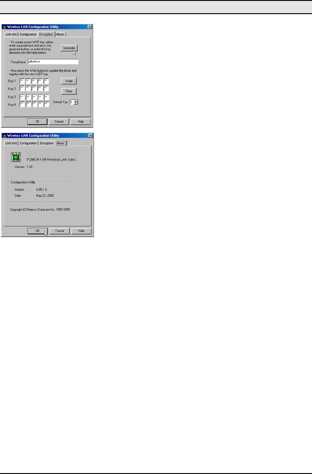
The Encryption window enables you to
create an encryption scheme for
Wireless LAN transmissions. Enter a
passphrase and press Generate to
automatically generate a 64- or 128-
bit key (selected from the WEP drop-
down menu in the Configuration
screen).
You can also manually enter a set of
values for each key.
Note: 128-bit encryption requires mo-
re system resources than 64-bit
encryption. Use 64-bit encryption for
better performance.
This screen displays the version num-
ber of the Wireless LAN card and the
Configuration Utility.

8
Appendix A
Troubleshooting
Q&A
These guidelines give you tips to deal with some problems you may encounter while using the Wireless LAN
module.
Question: Can not connect to one of the clients in the network.
Answer: First of all, make sure that all clients are up and running with a green Wireless Utility icon.
And please check your TCP/IP setup is correct for your network.

9
Appendix B
Specifications
Standards Compliance: IEEE802.11b WLAN Standard,
PCMCIA 2.1 and JEIDA 4.2 Standard
Socket Interface: 68-pin 16-bit PCMCIA socket connector
Card Size: PCMCIA extended Type II
Frequency: 2.412 to 2.462GHz ( Industrial Scientific Medical
Band )
Antenna: Dipole Antenna
Roaming: 802.11 compliant
Data Rate: 11Mbps / 5.5Mbps / 2Mbps / 1Mbps
Modulation Technique: Direct Sequence Spread Spectrum
BPSK / QPSK / CCK
Coverage Area: Close Space : 45m @ 11Mbps,
150m @ 5.5Mbps or lower
Power: DC +3.3V /+5V, 220mA (3.3V)
Output Power:
18.5dBm (typical)
Receiver Sensitivity: -82dBm Min.
Operating Environment: Temperature: 0o to 55oC
Humidity: 10% to 90%