Cisco Linksys WMP51AB Dual-Band Wireless A+B PCI Adapter User Manual test
Cisco-Linksys, LLC Dual-Band Wireless A+B PCI Adapter test
Revised Manual

Instant Wireless
®
Series
Dual-Band Wireless A+B
Network PCI Adapter
Use this guide to install: WMP51AB
User Guide
INDUSTRY CANADA (CANADA)
This Class B digital apparatus complies with Canadian ICES-003.
Cet appareil numérique de la classe B est conforme à la norme NMB-003 du Canada.
The use of this device in a system operating either partially or completely outdoors may require
the user to obtain a license for the system according to the Canadian regulations.
EC DECLARATION OF CONFORMITY (EUROPE)
Linksys Group declares that the Instant Wireless Series products included in the Instant
Wireless Series conform to the specifications listed below, following the provisions of the
EMC Directive 89/336/EEC and Low Voltage Directive 73/23/EEC:
• ETS 300-826, 301 489-1 General EMC requirements for Radio equipment.
• EN 609 50 Safety
• ETS 300-328-2 Technical requirements for Radio equipment.
Note: This equipment is intended to be used in all EU and EFTA countries. Outdoor use
may be restricted to certain frequencies and/or may require a license for operation. For
more details, contact Linksys Corporate Compliance.
Note: Combinations of power levels and antennas resulting in a radiated power level of
above 100 mW are considered as not compliant with the above mentioned directive and
are not allowed for use within the European community and countries that have adopted
the European R&TTE directive 1999/5/EC and/or the CEPT recommendation Rec 70.03.
For more details on legal combinations of power levels and antennas, contact Linksys
Corporate Compliance.
• Linksys Group vakuuttaa täten että Instant Wireless IEEE 802.11 PC Card tyyppinen
laite on direktiivin 1999/5/EY, direktiivin 89/336/EEC ja direktiivin 73/23/EEC oleellis-ten
vaatimusten ja sitä koskevien näiden direktiivien muiden ehtojen mukainen.
• Linksys Group déclare que la carte PC Instant Wireless IEEE 802.11 est conforme
aux conditions essentielles et aux dispositions relatives à la directive 1999/5/EC, la
directive 89/336/EEC, et à la directive 73/23/EEC.
• Belgique B L’utilisation en extérieur est autorisé sur le canal 11 (2462 MHz), 12 (2467
MHz), et 13 (2472 MHz).
Dans le cas d’une utilisation privée, à l’extérieur d’un bâtiment, au-dessus d’un
espace public, aucun enregistrement n’est nécessaire pour une distance de moins
de 300m. Pour une distance supérieure à 300m un enregistrement auprès de l’IBPT
est requise. Pour une utilisation publique à l’extérieur de bâtiments, une licence de
l’IBPT est requise. Pour les enregistrements et licences, veuillez contacter l’IBPT.
• France F: Bande de fréquence restreinte: seuls les canaux 10, 11, 12, 13 (2457,
2462, 2467, et 2472 MHz respectivement) doivent être utilisés en France. Toute util-isation,
qu'elle soit intérieure ou extérieure, est soumise à autorisation. Vous pouvez
contacter l'Autorité de Régulation des Télécommuniations (http://www.art-telecom.fr)
pour la procédure à suivre.
• France F: Restricted frequency band: only channels 10, 11, 12, 13 (2457, 2462,
2467, and 2472 MHz respectively) may be used in France. License required for
every indoor and outdoor installations. Please contact ART for procedure to follow.
• Deutschland D: Anmeldung im Outdoor-Bereich notwending, aber nicht genehmi-gungspflichtig.
Bitte mit Händler die Vorgehensweise abstimmen.
• Germany D: License required for outdoor installations. Check with reseller for proce-dure
to follow.
• Italia I: E' necessaria la concessione ministeriale anche per l'uso interno. Verificare
con i rivenditori la procedura da seguire. L'uso per installazione in esterni non e' per-messa.
• Italy I: License required for indoor use. Use with outdoor installations not allowed.
• the Netherlands NL License required for outdoor installations. Check with reseller for
procedure to follow.
• Nederlands NL Licentie verplicht voor gebruik met buitenantennes. Neem contact op
met verkoper voor juiste procedure.
COPYRIGHT & TRADEMARKS
Copyright © 2002 Linksys, All Rights Reserved. Instant Wireless, Linksys, and the Linksys logo
are registered trademarks of Linksys Group, Inc. Microsoft, Windows, and the Windows logo
are registered trademarks of Microsoft Corporation. All other trademarks and brand names are
the property of their respective proprietors.
LIMITED WARRANTY
Linksys guarantees that every Instant Wireless Dual-Band Wireless A+B Notebook Adapter will
be free from physical defects in material and workmanship under normal use for one year from
the date of purchase, when used within the limits set forth in the Specifications chapter of this
User Guide. If these products prove defective during this warranty period, call Linksys
Technical Support in order to obtain a Return Authorization Number. BE SURE TO HAVE YOUR
PROOF OF PURCHASE AND A BARCODE FROM THE PRODUCT'S PACKAGING ON HAND
WHEN CALLING. RETURN REQUESTS CANNOT BE PROCESSED WITHOUT PROOF OF PUR-CHASE.
When returning a product, mark the Return Authorization Number clearly on the out-side
of the package and include a copy of your original proof of purchase. All customers locat-ed
outside of the United States of America and Canada shall be held responsible for shipping
and handling charges.
IN NO EVENT SHALL LINKSYS’S LIABILITY EXCEED THE PRICE PAID FOR THE PRODUCT
FROM DIRECT, INDIRECT, SPECIAL, INCIDENTAL, OR CONSEQUENTIAL DAMAGES
RESULTING FROM THE USE OF THE PRODUCT, ITS ACCOMPANYING SOFTWARE, OR ITS
DOCUMENTATION. LINKSYS DOES NOT OFFER REFUNDS FOR ANY PRODUCT. Linksys
makes no warranty or representation, expressed, implied, or statutory, with respect to its prod-ucts
or the contents or use of this documentation and all accompanying software, and specif-ically
disclaims its quality, performance, merchantability, or fitness for any particular purpose.
Linksys reserves the right to revise or update its products, software, or documentation without
obligation to notify any individual or entity. Please direct all inquiries to:
Linksys P.O. Box 18558, Irvine, CA 92623.
FCC STATEMENT
This Instant Wireless Dual-Band Wireless A+B Notebook Adapter has been tested and com-plies
with the specifications for a Class B digital device, pursuant to Part 15 of the FCC Rules.
These limits are designed to provide reasonable protection against harmful interference in a res-idential
installation. This equipment generates, uses, and can radiate radio frequency energy
and, if not installed and used according to the instructions, may cause harmful interference to
radio communications. However, there is no guarantee that interference will not occur in a par-ticular
installation. If this equipment does cause harmful interference to radio or television recep-tion,
which is found by turning the equipment off and on, the user is encouraged to try to correct
the interference by one or more of the following measures:
• Reorient or relocate the receiving antenna
• Increase the separation between the equipment or devices
• Connect the equipment to an outlet other than the receiver’s
• Consult a dealer or an experienced radio/TV technician for assistance
FCC Caution: Any changes or modifications nor expressly approved by the party responsible
for compliance could void the user's authority to operate this equipment.
This device complies with Part 15 of the FCC Rules. Operation is subject to the following two
conditions: (1) This device may not cause harmful interference, and (2) This device must
accept any interference received, including interference that may cause undesired operation.
FCC RF Radiation Exposure Statement
This device and its antenna(s) must operate with a separation distance of at least 20 cm from
all persons and must not be co-located or operating in conjunction with any other antenna or
transmitter. End-users must be provided with specific operations for satisfying RF exposure
compliance.
UG-WPC51AB-102102NC JL
Table of Contents
Chapter 1:Introduction 1
The Dual-Band Wireless A+BNotebook Adapter 1
Features 1
Chapter 2:Planning Your Wireless Network 2
Network Topology 2
Ad-Hoc versus Infrastructure Mode 2
Chapter 3:Getting to Know the Dual-Band
Wireless A+B Notebook Adapter 4
The Adapter’s LEDs 4
Chapter 4:Software Installation and Configuration 5
Overview 5
Setup Wizard Instructions for Windows 98, Me, and 2000 6
Setup Wizard Instructions for Windows XP 10
Chapter 5:Hardware Installation 12
Chapter 6:Using the WLANMonitor for Windows
98, Me, and 2000 13
Overview 13
Accessing the WLANMonitor 13
Link Information 14
Site Survey 16
Profiles 18
Creating a New Profile 20
Chapter 7: Using the Wireless Zero Configuration
for Windows XP 28
Appendix A:Troubleshooting 30
Common Problems and Solutions 30
Frequently Asked Questions 31
Appendix B:Glossary 35
Appendix C: Specifications 40
Environmental 41
Appendix D: Warranty Information 42
Appendix E:Contact Information 43
Chapter 1:Introduction
The Linksys Dual-Band Wireless A+BNotebook Adapter lets your notebook
communicate with today’s wireless network standard and prepares you for the
future. With one PCCard, you can connect with the 2.4GHz, 802.11b wireless
networks so prevalent in homes, businesses and public “hotspots” already, and
also a growing number of 5GHz, 802.11a networks that are spreading across
the country.
It’s simple to use. Just pop it into a PCCard slot, and run the included Setup
Wizard, which will walk you through the configuration. To keep your commu-
nications
secure, the PCCard supports up to 152-bit data encryption.
802.11b wireless networks are commonly found in corporate environments and
are used in homes for household Internet connectivity without the need for run-
ning
cables. They’re also popping up all over the country in coffee shops, air-ports,
hotels, convention centers, and other public spaces offering “on-the-go”
connectivity to mobile users. The 802.11a standard is almost five times faster
than 802.11b, and operates in the less crowded 5GHz radio band, but it’s not as
common —yet. It is quickly being deployed wherever higher-speed connectivi-ty
is desired.
Join the wireless revolution. With the Linksys Dual-Band Wireless Notebook
Adapter, you’ll be ready to connect to either type of wireless network, wherev-er
you go, now and in the future.
•Connects to Either 802.11b (2.4GHz) or 802.11a (5GHz) Networks without
Changing Adapters
•Up to 152-bit WEPEncryption
•Easy-to-use Setup Wizard
•Detailed Monitoring and Performance Utility
•802.11b and 802.11a Compliant
•Free Technical Support —24 Hours a Day, 7 Days a Week, Toll-Free US
Calls
•1-Year Limited Warranty
The Dual-Band Wireless A+BNotebook Adapter
Features
Chapter 2: Planning Your
Wireless Network
A wireless local area network (WLAN) is exactly like a regular local area net-work
(LAN), except that each computer in the WLAN uses a wireless device to
connect to the network. Computers in a WLAN share the same frequency
channel and SSID, which is an identification name for wireless devices.
Unlike wired networks, wireless networks have two different modes in which
they may be set up: infrastructure and ad-hoc. An infrastructure configura-tion
is a WLAN and wired LAN communicating to each other through an
access point. An ad-hoc configuration is wireless-equipped computers com-municating
directly with each other. Choosing between these two modes
depends on whether or not the wireless network needs to share data or periph-erals
with a wired network or not.
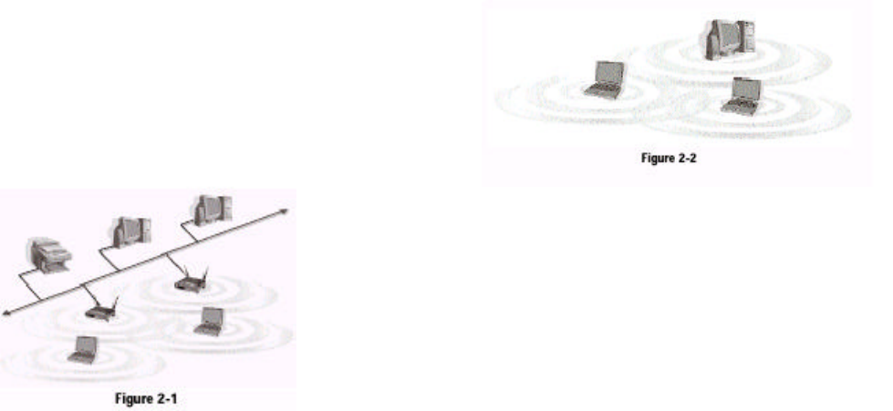
If the computers on the
wireless network need to
be accessed by a wired
network or need to share a
peripheral, such as a print-er,
with the wired network
computers, the wireless
network should be set up
in infrastructure mode.
(See Figure 2-1.) The
basis of infrastructure
mode centers around an
access point, which serves
as the main point of communications in a wireless network. Access points
transmit data to PCs equipped with wireless network cards, which can roam
within a certain radial range of the access point. Multiple access points can be
arranged to work in succession to extend the roaming range, and can be set up
to communicate with your Ethernet (wired) hardware as well.
Network Topology
Ad-Hoc versus Infrastructure Mode
Figure 2-1
If the wireless network is relatively small and needs to share resources only
with the other computers on the wireless network, then the ad-hoc mode can
be used. (See Figure 2-2.) Ad-hoc mode allows computers equipped with wire-less
transmitters and receivers to communicate directly with each other, elimi-nating
the need for an access point. The drawback of this mode is that, in Ad-Hoc
mode, wireless-equipped computers are not able to communicate with
computers on a wired network. And, of course, communication between the
wireless-equipped computers is limited by the distance and interference direct-ly
between them.
Chapter 3: Getting to Know the
Dual-Band Wireless A+ B
Notebook Adapter
Flash alternately
Green. The LEDs flash in alternate sequence, one after another, when the
Adapter is searching for an access point or wireless router.
Flash in unison
Green. The LEDs flash in unison when the Adapter is connected to an access
point or wireless router.
The Adapter’s LEDs
Figure 3-1
Chapter 4: Software Installation
and Configuration
The Dual-Band Wireless A+B Notebook Adapter Setup Wizard will guide you
through the installation procedure. The Setup Wizard will install the WLAN
Monitor and Device Driver, as well as configure the Adapter.
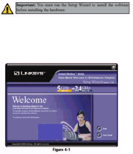
Insert the Setup Wizard CD-ROM into your CD-ROM drive. The Setup
Wizard should run automatically, and Figure 4-1 should appear. If it does not,
click the Start button and choose Run. In the field that appears, enter
D:\setup.exe (if “D” is the letter of your CD-ROM drive).
If your PC is using Windows 98, Me, or 2000, proceed to the next section,
“Setup Wizard Instructions for Windows 98, Me, and 2000.” If your PC is using
Windows XP, proceed to this section, “Setup Wizard Instructions for Windows
XP.”
Important: You must run the Setup Wizard to install the software
before installing the hardware.
Figure 4-1
Overview
1. To install the Adapter, click the Next button on the Welcome screen.
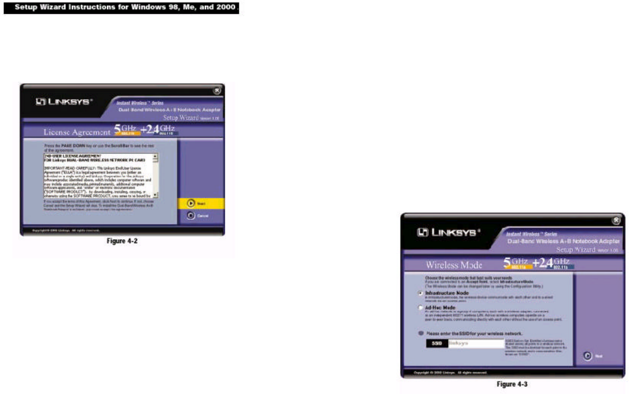
2. After reading the License Agreement, click the Next button if you agree, or
click the Cancel button to end the installation.
3. The Setup Wizard will ask you to choose a wireless mode. Click the
Infrastructure Mode radio button if you want your wireless computers to
network with computers on your wired network using a wireless access
point. Click the Ad-Hoc Mode radio button if you want multiple wireless
computers to network directly with each other. Do not use the Ad-Hoc mode
if you want your wireless computers to communicate with computers on
your wired network.
In the SSID field, enter the SSID of your wireless network. The SSID must
be identical for all devices in the network. The default setting is linksys (all
lowercase). Click the Next button.
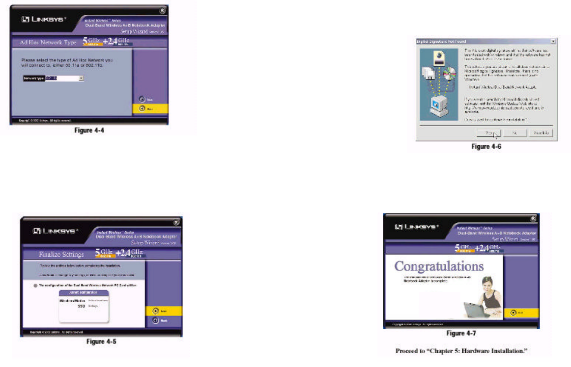
4. If you chose Infrastructure Mode, go to Step 5 now. If you chose Ad-Hoc
Mode, select the type of network your PC will connect to, 802.11a or
802.11b. Click the Next button, and go to Step 5. Click the Back button to
change any settings.
5. The Setup Wizard will ask you to review your settings before it starts to copy
files. Click the Next button to save these settings, or click the Back button
to change any settings.
6. For Windows 2000, you may be informed that a digital signature has not
been found (see Figure 4-6). This is normal, and it has been verified that the
Adapter does work with Windows 2000. Click the Ye s button to continue.
Windows will begin installing the driver files. If Windows asks you for the
original Windows CD-ROM, insert the CD-ROM, and direct Windows to the
proper location for the CD-ROM (e.g., D:\).
7. After the files have been successfully copied, the screen in Figure 4-7 will
appear. Click the Exit button.
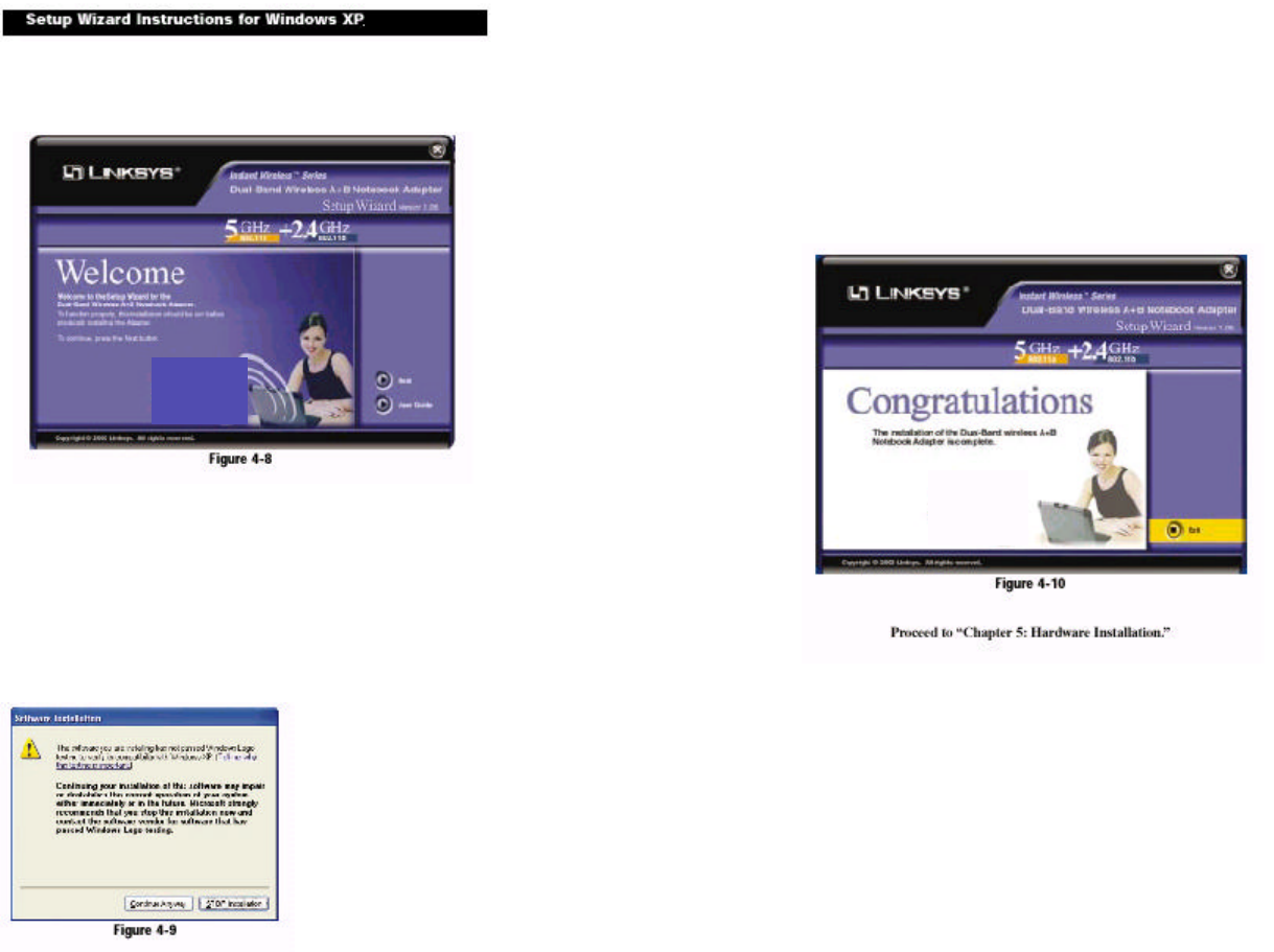
1. To install the Adapter, click the Next button on the Welcome screen.
2. Windows will notify you that the driver has not passed Windows Logo test-ing.
This is normal, and it has been verified that the Adapter does work with
Windows XP. Click the Continue Anyway button.
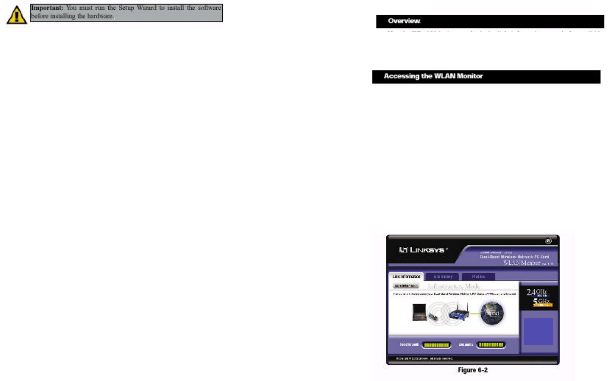
3. After the files have been successfully copied, the screen in Figure 4-10 will
appear. Click the Exit button.
Chapter 5: Hardware
Installation
1. Remove any CDs or disks from their drives, and turn off your notebook PC.
2. Locate an available PCMCIA slot on your notebook PC.
3. With the Adapter’s 68-pin connecting facing the PCMCIA slot and the
“Dual-Band Wireless A+B Notebook Adapter” label facing up,
lide the Adapter completely into the PCMCIA slot.
4. Restart your notebook PC.
5. You may see several screens appear as the driver installation is finalized. For
Windows 2000, you may be informed that a digital signature has not been
found. This is normal, and it has been verified that the Adapter does work
with Windows 2000. Click the Ye s button to continue, and click the Finish
button to complete the installation.
Congratulations! The installation of the Dual-Band Wireless A+B
Notebook Adapter is complete.
If your PC is using Windows 98, Me, or 2000, proceed to the next section,
“Chapter 6: Using the WLAN Monitor for Windows 98, Me, and 2000.”
If your PC is using Windows XP, proceed to “Chapter 7: Using the
Wireless Zero Configuration for Windows XP.”
Important: You must run the Setup Wizard to install the software
before installing the hardware.
Figure 5-1
Chapter 6: Using the WLAN
Monitor for Windows 98, Me, and
2000
Use the WLAN Monitor to check the link information, search for available
wireless networks, or create profiles that hold different configuration settings.
After installing the Adapter,
the Dual-Band Wireless A+B
Notebook Adapter WLAN Monitor icon will appear in your sys-tem
tray. Double-click the icon (see Figure 6-1).
The Link Information screen will appear. From this screen, you can find out
how strong the current wireless signal is and how good the connection’s quali-ty
is. You can also click the More Information button to view additional status
information about the current wireless connection. To search for available wire-less
networks, click the Site Survey tab. To perform configuration changes,
click the Profiles tab.
Figure 6-1
Accessing the WLAN Monitor
Overview
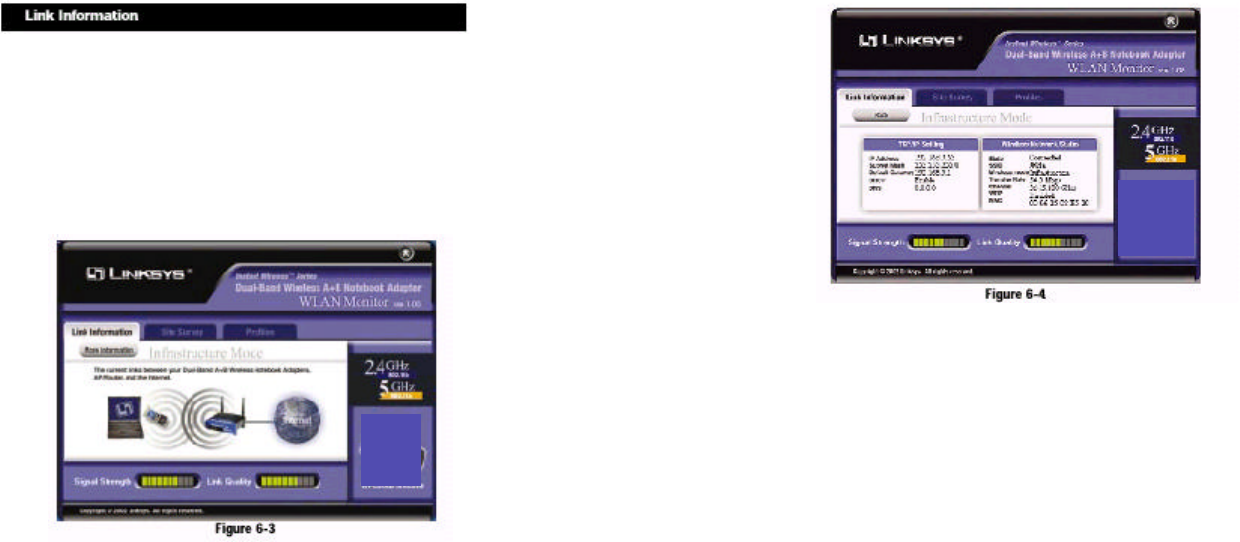
The Link Information screen displays signal strength and link quality informa-tion
about the current connection and provides a button to click for additional
status information.
Ad-Hoc Mode or Infrastructure Mode - The screen indicates whether the
Adapter is currently working in ad-hoc or infrastructure mode.
Signal Strength - The Signal Strength bar indicates signal strength, from 0 to
100%.
Link Quality - The Link Quality bar indicates the quality of the wireless net-work
connection, from 0 to 100%.
Click the More Information button to view more information about the wire-less
network connection.
Click the X (Close) button in the upper right corner to exit the WLAN Monitor.
TCP/IP Setting
IP Address - The IP Address of the Adapter.
Subnet Mask - The Subnet Mask of the Adapter.
Default Gateway - The Default Gateway address of the Adapter.
DHCP - The status of the DHCP client.
DNS - The DNS address of the Adapter.
Wireless Network Status
State - The status of the wireless network connection.
SSID - The unique name of the wireless network.
Wireless Mode - The mode of the wireless network currently in use.
Transfer Rate - The data transfer rate of the current connection.
Channel - The channel to which the wireless network devices are set.
WEP - The status of the WEP encryption security feature.
MAC - The MAC address of the wireless network’s access point.
Signal Strength - The Signal Strength bar indicates signal strength, from 0 to
100%.
Link Quality - The Link Quality bar indicates the quality of the wireless net-work
connection, from 0 to 100%.
Click the Back button to return to the initial Link Information screen. Click the
X (Close) button in the upper right corner to exit the WLAN Monitor.
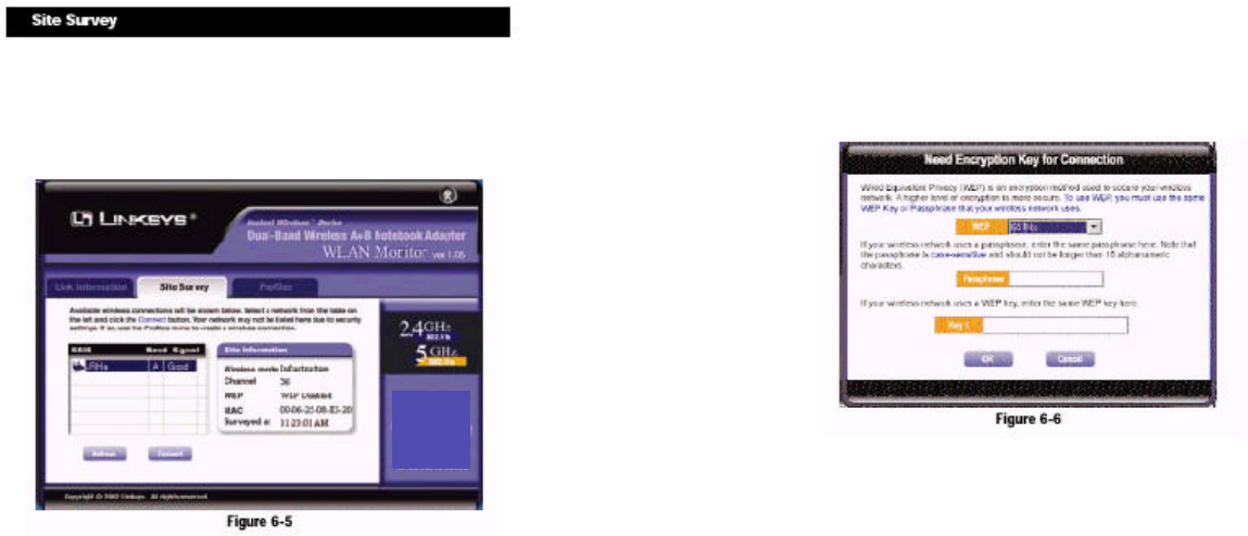
The Site Survey screen displays a list of infrastructure and ad-hoc networks
available for connection.
SSID - The SSID or unique name of the wireless network.
Band - The type of wireless network. “A” represents 802.11a (5GHz), and “B”
represents 802.11b (2.4GHz).
Signal - The percentage of signal strength, from 0 to 100%.
Site Information
Wireless Mode - The mode of the wireless network currently in use.
Channel - The channel to which the wireless network devices are set.
WEP - The status of the WEP encryption security feature.
MAC - The MAC address of the wireless network’s access point.
Surveyed at - The time at which the wireless network was scanned.
Refresh - Click the Refresh button to perform a new search for wireless
devices.
Connect - To connect to one of the networks on the list, select the wireless net-work,
and click the Connect button. If the wireless network has WEP encryp-tion
enabled, you will see the screen shown in Figure 6-6.
In the WEP drop-down box, select the type of WEP encryption used by the
wireless network: 64-bi t, 128-bit, or 152-bit WEP.
If the wireless network uses a passphrase, enter the passphrase in the
Passphrase field. If the wireless network uses a WEP key, enter the WEP key
in the Key 1 field.
Click the OK button to complete the network connection and return to the Site
Survey screen, or click the Cancel button to cancel the network connection and
return to the Site Survey screen.
On the Site Survey screen, click the X (Close) button in the upper right corner
to exit the WLAN Monitor.
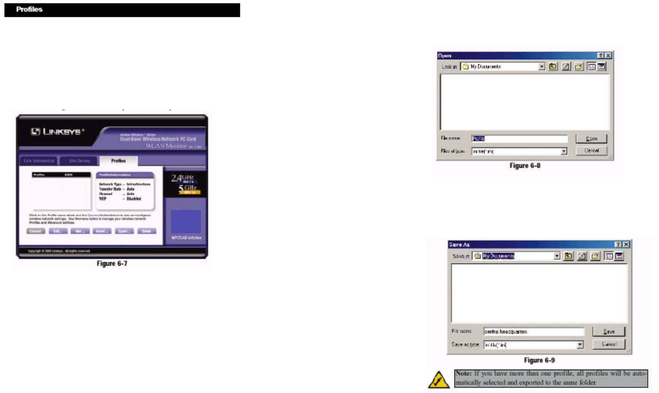
The Profiles screen lets you save different configuration profiles for different
network setups. You can also import or export profiles. The default profile
holds the initial configuration saved when you ran the Setup Wizard.
Profile - Name of the connection profile.
SSID - The wireless network’s unique name, as set in the connection profile.
Profile Information
Network Type - The mode of the wireless network currently in use.
Transfer Rate - The data transfer rate of the current connection. (In Auto
mode, the Adapter dynamically shifts to the fastest data transfer rate possible
at any given time.)
Channel - The channel to which the wireless network devices are set.
WEP - The status of the WEP encryption security feature.
Connect - To connect to a wireless network using a specific profile, select the
profile, and click the Connect button.
Edit - Select a profile, and click the Edit button to change an existing profile.
New - Click the New button to create a new profile. See the next section,
“Creating a New Profile,” for detailed instructions.
Import - Click the Import button to import a profile that has been saved in
another location. Select the appropriate file, and click the Open button.
Export - To save the profile(s) in a different location, click the Export button.
Direct Windows to the appropriate folder, and click the Save button.
Delete - Click the Delete button to delete a profile.
Click the X (Close) button in the upper right corner to exit the WLAN Monitor.
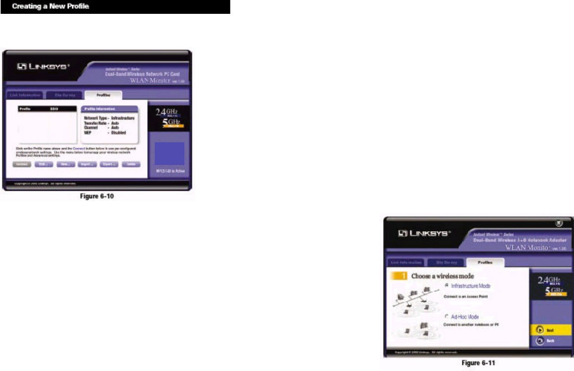
1. On the Profiles screen, click the New button to create a new profile.
2. The Choose a wireless mode screen shows a choice of two wireless modes.
Click the Infrastructure Mode radio button if you want your wireless
computers to communicate with computers on your wired network via a
wireless access point. Click the Ad-Hoc Mode radio button if you want
multiple wireless computers to communicate directly with each other.
Click the Next button to continue or the Back button to return to the previ-ous
screen.
Infrastructure Mode - This mode allows wireless and wired networks to
communicate through an access point.
Ad-Hoc Mode - This mode allows wireless-equipped computers to com-municate
directly with each other. No access point is used.
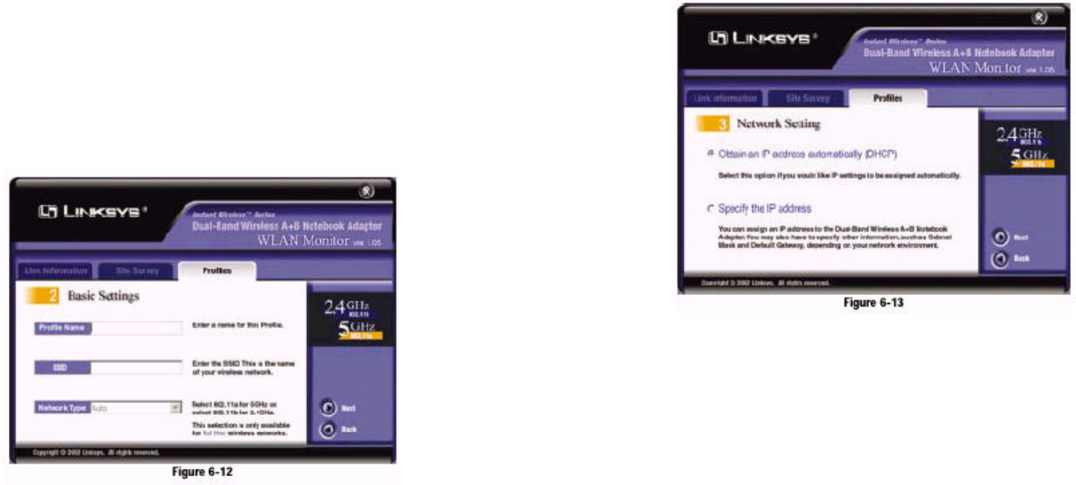
3. The Basic Settings screen will appear. Complete the Profile Name and SSID
fields. The default SSID setting is linksys (all lowercase). Then select the
appropriate setting from the Network Type drop-down box. Click the Next
button to continue or the Back button to return to the previous screen.
Profile Name - Give this new profile a name.
SSID - The SSID is the unique name shared by all devices in a wireless net-work.
The SSID must be identical for all devices in the wireless network. It
is case-sensitive and must not exceed 32 characters (use any of the charac-ters
on the keyboard). Make sure this setting is the same for all devices in
your wireless network.
Network Type - For infrastructure networks, the Network Type is set to
Auto and cannot be changed. For ad-hoc networks, choose the appropriate
setting, 802.11a (5GHz) or 802.11b (2.4GHz).
4. The Network Setting screen will appear.
If your network has a DHCP server, click the radio button next to Obtain
an IP address automatically (DHCP). Click the Next button to continue,
or click the Back button to return to the previous screen. Then go to step 6.
If your network does not have a DHCP server, click the radio button next to
Specify the IP address. Click the Next button to continue, or click the
Back button to return to the previous screen. Then go to step 5.
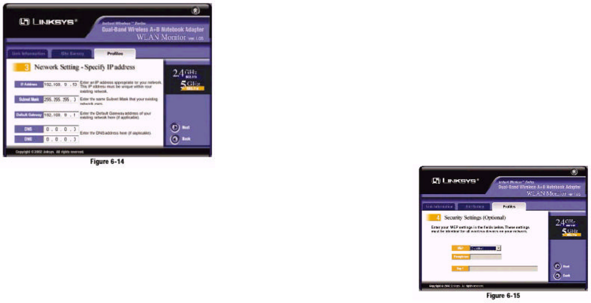
5. The Network Setting - Specify IP address screen will appear next. Enter an
IP Address, Subnet Mask, Default Gateway, and DNS appropriate for
your network. Enter each address in this format: xxx.xxx.xxx.xxx (the x’s
represent the numbers that make up each address). You must specify the IP
Address and Subnet Mask on this screen. If you are unsure about the
Default Gateway and DNS addresses, then leave these fields alone.
Click the Next button to continue or the Back button to return to the previ-ous
screen.
IP Address - This IP Address must be unique to your network.
Subnet Mask - The Adapter’s Subnet Mask must be the same as your wired
network’s Subnet Mask.
Default Gateway - Enter the IP address of your network’s Gateway here.
DNS - Enter the DNS addresses of your Ethernet (wired) network here.
6. If you are configuring the Adapter for a 2.4GHz, 802.11b network, then go
to step 7. If you are configuring the Adapter for a 2.4GHz, 802.11b net-work,
then go to step 8.
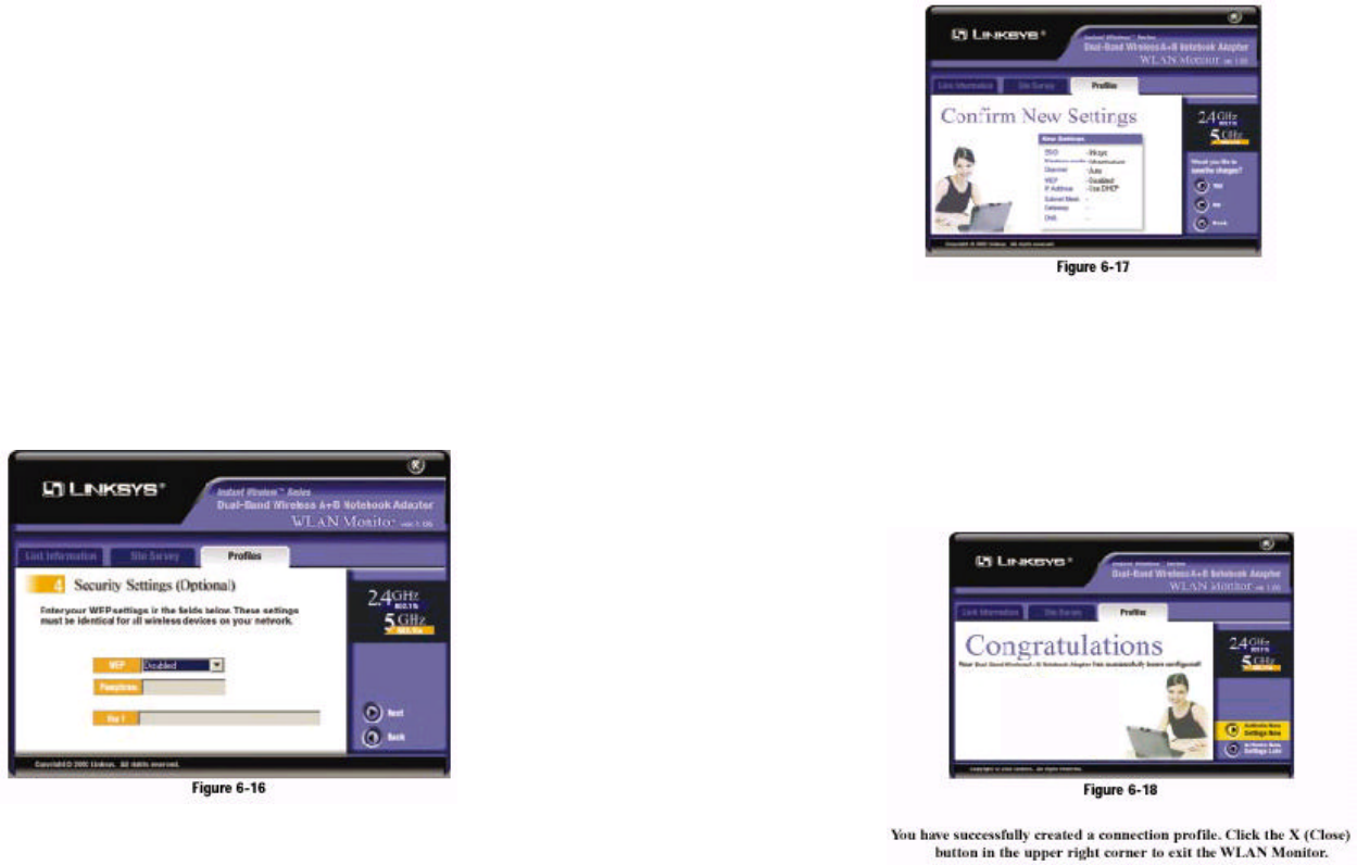
7. The Security Settings screen will appear next. Enable or disable Wired
Equivalent Privacy (WEP) encryption for your wireless network. If you
enable WEP, enter a Passphrase or WEP key. Click the Next button to con-tinue
or the Back button to return to the previous screen.
WEP (Disabled/64-bit WEP/128-bit WEP) - If you do not want to use
WEP encryption, choose Disabled. To use WEP encryption (recommended
to increase network security), select 64-bit or 128-bit WEP from the drop-down
menu, and enter either a Passphrase or WEP key.
Passphrase - Instead of manually entering WEP keys, you can enter a
Passphrase, so a WEP key is automatically generated. It is case-sensitive and
should not be longer than 16 alphanumeric characters. This passphrase must
match the passphrase of your wireless network and is compatible with
Linksys wireless products only. (If you have any non-Linksys wireless prod-ucts,
enter the WEP key(s) manually on those products.)
Key 1 - This WEP key must match the WEP key of your wireless network.
If you are using 64-bit WEP encryption, then the key must consist of exact-ly
10 hexadecimal characters in length. If you are using 128-bit WEP
encryption, then the key must consist of exactly 26 hexadecimal characters
in length. Valid hexadecimal characters are “0” to “9” and “A” to “F”.
8. The Security Settings screen will appear next. Set the Wired Equivalent
Privacy (WEP) encryption for your wireless network by selecting a WEP
configuration method (recommended to increase network security). If you
enable WEP encryption, enter a WEP key in the Key 1 field. Click the Next
button to continue or the Back button to return to the previous screen.
WEP (Disabled/64-bit WEP/128-bit WEP/152-bit WEP) - If you do not
want to use WEP encryption, choose Disabled.
To use WEP encryption, select 64-bi t, 128-bit WEP, or 152-bit WEP from
the drop-down menu. Then enter the WEP key of your wireless network in
the Key 1 field.
Key 1 - This WEP key must match the WEP key of your wireless network.
If you are using 64-bit WEP encryption, then the key must consist of exact-ly
10 hexadecimal characters in length. If you are using 128-bit WEP
encryption, then the key must consist of exactly 26 hexadecimal characters
in length. Valid hexadecimal characters are “0” to “9” and “A” to “F”.
9. The Confirm New Settings screen will appear next. The former and new set-tings
are shown. To save the new settings, click the Ye s button. To cancel
the settings and return to the Profiles screen, click the No button. To edit
the new settings, click the Back button.
10. The Congratulations screen will appear next. Click Activate new settings
now to implement the new settings immediately and return to the Link
Information screen. Click Activate new settings later to keep the current
settings active and return to the Profiles screen.
Chapter 7: Using the Wireless Zero
Configuration for Windows XP
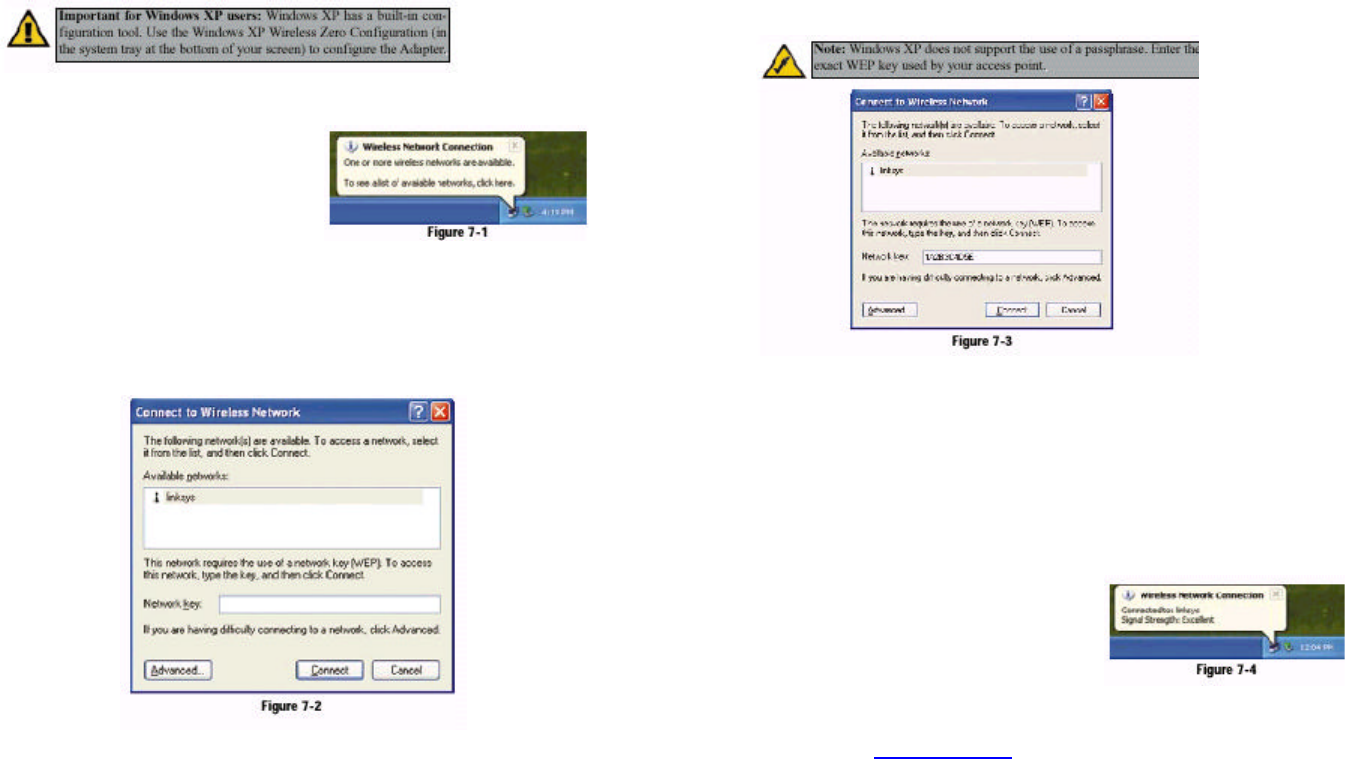
1. After installing the Adapter,
the Windows XP Wireless
Zero Configuration icon
will appear in your comput-er’s
system tray (see Figure
7-1). Double-click the icon.
2. The screen that appears will show any available wireless network. Select a
network, and then click the Connect button.
3. If your access point has WEP encryption enabled, the screen in Figure 7-3
will appear. Enter the WEP key of your wireless network in the Network key
field. Click the Connect button.
To find the WEP encryption key settings of the other wireless devices in
your network, such as an access point or wireless router, you may use any
device’s web-based utility to check the WEP encryption screen for the cor-rect
key entries. If you are using other manufacturers’ access points, refer
to their documentation for more information about WEP encryption.
4. The screen in Figure 7-4 will
appear if your connection is
active.
For more information about WEP,
refer to your access point’s user
guide, or visit www.linksys.com.
For more information about wireless networking on a Windows XP computer,
enter the keyword wireless in the Windows XP search engine.
Congratulations!
Your notebook has successfully connected to your wireless network.
Federal Communication Commission Interference
Statement
This equipment has been tested and found to comply with the limits
for a Class B digital device, pursuant to Part 15 of the FCC Rules.
These limits are designed to provide reasonable protection against
harmful interference in a residential installation. This equipment
generates, uses and can radiate radio frequency energy and, if not
installed and used in accordance with the instructions, may cause
harmful interference to radio communications. However, there is no
guarantee that interference will not occur in a particular installation.
If this equipment does cause harmful interference to radio or
television reception, which can be determined by turning the
equipment off and on, the user is encouraged to try to correct the
interference by one of the following measures:
- Reorient or relocate the receiving antenna.
- Increase the separation between the equipment and receiver.
- Connect the equipment into an outlet on a circuit different from
that to which the receiver is connected.
- Consult the dealer or an experienced radio/TV technician for help.
FCC Caution: To assure continued compliance, (example - use only
shielded interface cables when connecting to computer or
peripheral devices) any changes or modifications not expressly
approved by the party responsible for compliance could void the
user's authority to operate this equipment.
This device complies with Part 15 of the FCC Rules. Operation is
subject to the following two conditions: (1) This device may not
cause harmful interference, and (2) this device must accept any
interference received, including interference that may cause
undesired operation.
IMPORTANT NOTE:
FCC Radiation Exposure Statement:
This equipment complies with FCC radiation exposure limits set
forth for an uncontrolled environment. This equipment should be
installed and operated with minimum distance 20cm between the
radiator & your body.
This transmitter must not be co-located or operating in conjunction
with any other antenna or transmitter.
Frequency band 5150 - 5250 MHz out of doors will void the user's
authority to operate the equipment.