Cisco Systems 102042 Mini-PCI Card User Manual 12KDBQSG bk

Cisco Systems Inc Mini-PCI Card 12KDBQSG bk

Contents

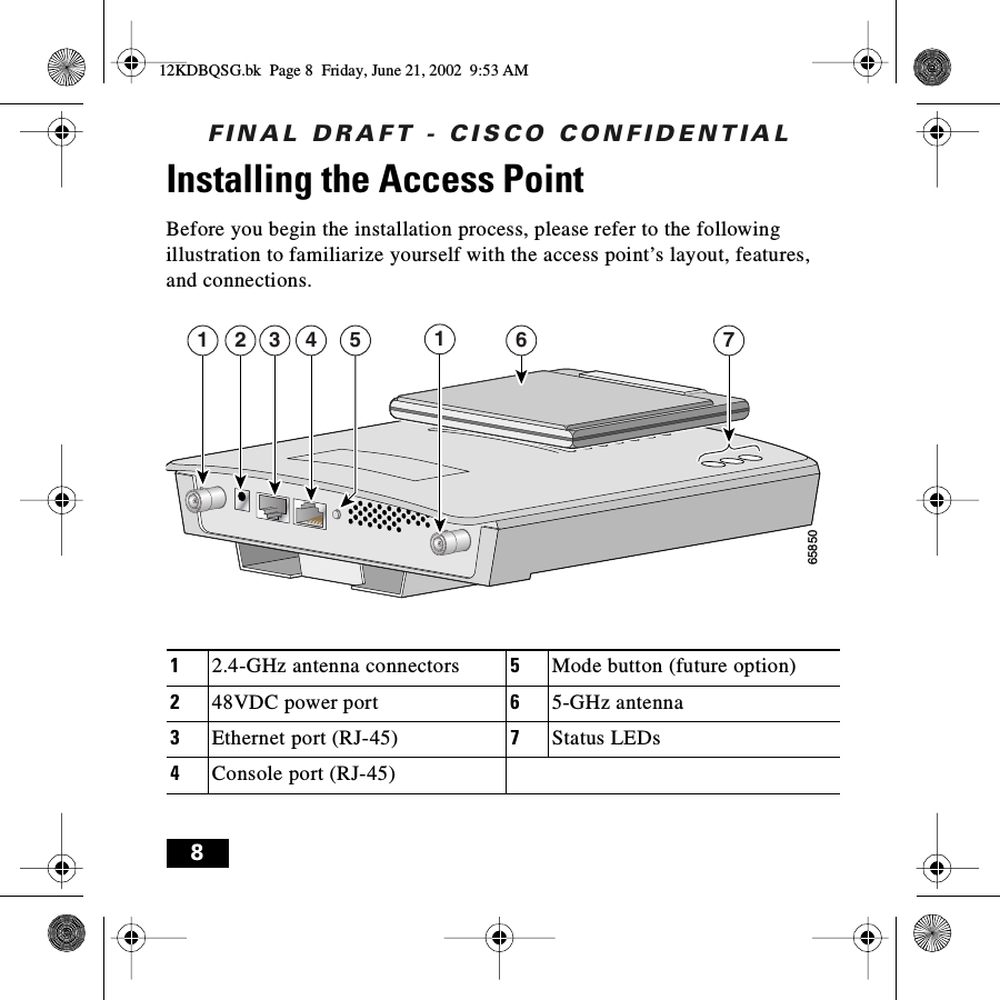
2002115 1200 AP dual mode QSG final draft 080802

FINAL DRAFT - CISCO CONFIDENTIALCisco One-Year Limited Hardware Warranty Terms 1Preface 5Introduction to the Access Point 6Unpacking the Access Point 7Installing the Access Point 8Additional Requirements 9Attaching and Adjusting the Antennas 102.4-GHz Dipole Antennas 105-GHz Integrated Antenna 11Connecting to an Ethernet Network with an Inline Power Source 12Connecting to an Ethernet Network with Local Power 13Powering Up the Access Point 14Obtaining and Assigning an IP Address 14Determining a DHCP Assigned IP Address 15Using IPSU 16Using a Terminal Emulator 1612KDBQSG.bk  Page 1  Friday, June 21, 2002  9:53 AM
FINAL DRAFT - CISCO CONFIDENTIALConfiguring the Access Point 17In Case of Difficulty 22Mounting Instructions 23Mounting on a Horizontal or Vertical Surface 26Mounting on a Suspended Ceiling 27Attaching the Access Point to the Mounting Bracket 29Securing the Access Point to the Mounting Bracket 30Safety Information 31Compliance Information 3212KDBQSG.bk  Page 2  Friday, June 21, 2002  9:53 AM
FINAL DRAFT - CISCO CONFIDENTIAL1Cisco One-Year Limited Hardware Warranty TermsThere are special terms applicable to your hardware warranty as well as services you may use during the warranty period.  Your formal Warranty Statement, including the warranty applicable to Cisco software, appears in the CD which accompanies your Cisco Product. Follow these steps to access and download the Cisco Information Packet and your warranty document from the CD or from Cisco.com.1. Launch your browser and go to the following URL:http://www.cisco.com/univercd/cc/td/doc/es_inpck/cetrans.htmThe Warranties and License Agreement page appears.2. To view the Cisco Information Packet, perform these steps:a. Click the Information Packet Number field and make sure that the part number 78-5235-02E0 is highlighted.b. Select the language to view the document.c. Click Go. The Information Packet page appears.d. From this page you can review the document online or click the PDF icon to download and print the document in Adobe Portable Document Format (PDF).12KDBQSG.bk  Page 1  Friday, June 21, 2002  9:53 AM
FINAL DRAFT - CISCO CONFIDENTIAL2Note You must have Adobe Acrobat Reader in order to view and print a PDF file. If you do not have the viewer, click the Get Acrobat Reader icon at the bottom of the page to go to the Adobe.com website and download the reader.3. To view translated and/or localized warranty information about your product, follow these steps:a. Enter the following part number in the Warranty Document Number field:78-10747-01C0b. Select the language to view the document.c. Click Go. The Cisco Warranty page appears.From this page you can review the document online or click the PDF icon to download and print the document in Adobe Portable Document Format (PDF).You may also contact our Service and Support website for assistance at:http://www.cisco.com/public/Support_root.shtml.Duration of Hardware WarrantyOne (1) Year12KDBQSG.bk  Page 2  Friday, June 21, 2002  9:53 AM
FINAL DRAFT - CISCO CONFIDENTIAL3Replacement, Repair or Refund Procedure for Hardware Cisco or its service center will use commercially reasonable efforts to ship a replacement part within ten (10) working days after receipt of the RMA request. Actual delivery times may vary depending on Customer location.Cisco reserves the right to refund the purchase price as its exclusive warranty remedy.To Receive a Return Materials Authorization (RMA) NumberPlease contact the party from whom you purchased the product. If you purchased the product directly from Cisco, contact your Cisco Sales and Service Representative. Complete the information below and keep for ready reference. Product purchased from:Their telephone number:Product Model and Serial number:Maintenance Contract number:12KDBQSG.bk  Page 3  Friday, June 21, 2002  9:53 AM
FINAL DRAFT - CISCO CONFIDENTIAL4Note Depending on the 1200 series configuration purchased, your product may consist of multiple product model numbers. Please record all product and serial numbers received so you can refer to them if you need to obtain an RMA number.12KDBQSG.bk  Page 4  Friday, June 21, 2002  9:53 AM
FINAL DRAFT - CISCO CONFIDENTIAL5PrefaceThis guide is designed to help you install and minimally configure your Cisco Aironet 1200 Series Access Point in a wireless Local Area Network (LAN). Detailed installation and configuration information can be found in the Cisco Aironet 1200 Series Access Point Hardware Installation Guide and Cisco Aironet 1200 Series Access Point Software Configuration Guide, which are on Cisco.com. Another document, Radio Upgrade Instructions: Cisco Aironet 1200 Series Access Points, is shipped with radio upgrade kits for 2.4- and 5-GHz radios.Follow these steps to access these documents:1. Browse to http://www.cisco.com.2. In the Service & Support section, click Technical Documents. The Cisco Documentation page appears.3. Click Wireless. The Documentation page appears.4. Click Aironet 1200 Series Wireless LAN Products. The Aironet 1200 Series Wireless LAN Products page appears.5. Click Cisco Aironet 1200 Series Access Points. The Cisco Aironet 1200 Series Access Points page appears.6. Click on the document you wish to open.12KDBQSG.bk  Page 5  Friday, June 21, 2002  9:53 AM
FINAL DRAFT - CISCO CONFIDENTIAL6Introduction to the Access PointThe Cisco Aironet 1200 Series Access Point delivers a cost-effective, reliable, secure, and easily-managed wireless LAN solution for enterprise customers and for small and medium sized businesses. The access point is designed to incorporate new technology enhancements as they become available. The access point can contain one or two wireless LAN transceivers (radios). Each transceiver serves as the center point of a stand-alone wireless network or as the connection point between wireless and wired networks. In large installations, wireless users within radio range of an access point can roam throughout a facility while maintaining uninterrupted access to the network.The access point can support simultaneous dual-band (2.4-GHz and 5-GHz) radio operation or can be configured from the factory for single-band operation: 2.4-GHz only or 5-GHz only. The single band radio units can be later filed upgraded for dual band operation through the addition of a 5-GHz radio module or a 2.4-GHz radio card.Note This guide provides information about the dual-band configuration. Your access point’s configuration may vary depending on the what you ordered.12KDBQSG.bk  Page 6  Friday, June 21, 2002  9:53 AM
FINAL DRAFT - CISCO CONFIDENTIAL7Unpacking the Access PointEach access point is shipped with the following items:•Access point power pack•Mounting bracket•Mounting hardware kit•This quick start guide•Product registration cardNote Antennas for the 2.4-GHz radio are not included in the shipping container and must be ordered separately. Contact your Cisco representative for further information.If anything is missing or damaged, contact your Cisco representative for support. 12KDBQSG.bk  Page 7  Friday, June 21, 2002  9:53 AM
FINAL DRAFT - CISCO CONFIDENTIAL8Installing the Access PointBefore you begin the installation process, please refer to the following illustration to familiarize yourself with the access point’s layout, features, and connections.12.4-GHz antenna connectors 5Mode button (future option)248VDC power port 65-GHz antenna3Ethernet port (RJ-45) 7Status LEDs4Console port (RJ-45)658501 612 3 4 5 712KDBQSG.bk  Page 8  Friday, June 21, 2002  9:53 AM
FINAL DRAFT - CISCO CONFIDENTIAL9Note See the Cisco Aironet 1200 Series Access Point Hardware Installation Guide for a detailed description of these connections.You must perform the following procedures in order to make your access point operational:1. Attach and adjust the antennas.2. Connect the access point to your network.3. Power up the access point.4. Obtain an IP address.5. Configure the access point.Additional RequirementsBefore you install the access point, make sure you are using a computer connected to the same network as the access point, and obtain the following information:•The MAC address from the label on the bottom of the access point (such as 00164625854c)12KDBQSG.bk  Page 9  Friday, June 21, 2002  9:53 AM
FINAL DRAFT - CISCO CONFIDENTIAL10•The following information from your network system administrator:–The case-sensitive wireless service set identifier (SSID) for your radio network–If not connected to a DHCP server, a unique IP address for your access point (such as 172.17.255.115)–If the access point is not on the same subnet as your PC, a default gateway address and subnet maskNote Plan to configure the access point before mounting it in a relatively inaccessible location. Some steps, such as those requiring a serial cable, are easier to perform if the access point is accessible.Attaching and Adjusting the Antennas2.4-GHz Dipole AntennasAttach the antennas to the Reverse-Polarity Threaded Naval Connector (RP-TNC) connectors on the back of the access point and tighten hand tight.12KDBQSG.bk  Page 10  Friday, June 21, 2002  9:53 AM
FINAL DRAFT - CISCO CONFIDENTIAL11Adjust the antennas depending on how you intend to mount the access point:•Point the antenna straight up if the access point is mounted on a table or desk.•Point the antennas straight up if the access point is mounted on a vertical surface such as a wall, even though the access point is on its side.•Point the antennas straight down if the access point is mounted on a ceiling.5-GHz Integrated AntennaCaution To ensure optimum performance, the antenna housing must be n one of the two positions described below.The 5-GHz integrated antenna is already installed. Deploy the antenna depending on how the access point is mounted:•Unfold the antenna housing if the access point is mounted on a horizontal surface, such as a ceiling or desktop.•Leave the housing in the folded position if the access point is mounted on a vertical surface, such as a wall.12KDBQSG.bk  Page 11  Friday, June 21, 2002  9:53 AM
FINAL DRAFT - CISCO CONFIDENTIAL12Connecting to an Ethernet Network with an Inline Power SourceCaution Both the Ethernet and console ports use RJ-45 connectors. Make sure that you connect the cable to the Ethernet port and not to the console port.Follow these steps to connect the access point to the Ethernet LAN when you have an inline power source:1. Connect the Ethernet cable to the RJ-45 Ethernet connector labeled Ethernet on the access point. Connect the other end of the cable to one of the following:a. A switch with inline power, such as a Cisco Catalyst 3524-PWR-XL.b. An inline power switch panel, such as a Cisco Catalyst Inline Power Patch Panel.c. The end of a Cisco Aironet power injector labeled To AP/Bridge and the other end labeled To Networ k to the 10/100 Ethernet LAN.12KDBQSG.bk  Page 12  Friday, June 21, 2002  9:53 AM
FINAL DRAFT - CISCO CONFIDENTIAL13Connecting to an Ethernet Network with Local PowerCaution Both the Ethernet and console ports use RJ-45 connectors. Make sure that you connect the Ethernet cable to the Ethernet port and not to the console port.Follow these steps to connect the access point to an Ethernet LAN when you have a local power source:1. Connect the Ethernet cable to the RJ-45 Ethernet connector labeled Ethernet on the access point. 2. Connect the power pack’s power output connector to the 48-VDC power port labeled 48VDC on the access point.3. Plug the other end of the power pack into an approved 100 to 250 VAC outlet.12KDBQSG.bk  Page 13  Friday, June 21, 2002  9:53 AM
FINAL DRAFT - CISCO CONFIDENTIAL14Powering Up the Access PointWhen power is applied to the access point, it begins a routine power-up sequence that you can monitor by observing the three LEDs on top of the access point. All three LEDs on the top of the access point (Radio, Status, and Infrastructure) slowly blink amber, red, and green in sequence; the sequence takes a couple of minutes to complete.Note See the Cisco Aironet 1200 Series Access Point Hardware Installation Guide for a detailed description of the LED displays.When the sequence is complete, you are ready to associate an IP address with the access point and perform an initial configuration.Obtaining and Assigning an IP AddressYour access point must be assigned an IP address before you can configure it using your web browser to access its management pages. Before you can open the management pages, you need to obtain and assign an IP address for the access point using one of the following methods:•Use a DHCP server (if available) to automatically assign an IP address.12KDBQSG.bk  Page 14  Friday, June 21, 2002  9:53 AM
FINAL DRAFT - CISCO CONFIDENTIAL15•Use the IP Setup Utility (IPSU) if your computer’s operating system is Windows 9x, 2000, Me, NT, or XP.Note IPSU is available for downloading in the Software Center on Cisco.com.•Use a terminal emulator and the access point’s console port if your computer’s operating system is Windows CE, Linux, or Mac OS.Determining a DHCP Assigned IP AddressIf your network uses a DHCP server, the server automatically assigns an IP address to the access point. You can obtain the IP address by one of the following methods:•Provide your organization’s network administrator with your access point’s Media Access Control (MAC) address. Your network administrator will query the DHCP server using the MAC address to identify the IP address.Note The MAC address is printed on the serial number label attached to the bottom of the access point.12KDBQSG.bk  Page 15  Friday, June 21, 2002  9:53 AM
FINAL DRAFT - CISCO CONFIDENTIAL16•Use IPSU or a terminal emulator and the access point’s serial port to identify the assigned address.Using IPSUIf your computer is not connected to a DHCP server and the access point is on the same subnet as your PC, you can use IPSU to assign an IP address to the access point or identify an address already assigned.Procedures for installing and using IPSU can be found in the Cisco Aironet 1200 Series Access Point Hardware Installation Guide. The guide and IPSU are available on Cisco.com.Using a Terminal EmulatorYou can identify or assign an IP address using the access point’s console port and a terminal emulator for all operating systems. However, if your computer’s operating system is Windows CE, Linux, or Mac OS, you must use the access point’s command-line console.To access the command-line console, connect a rollover RJ-45 serial console cable (Cisco part number AIR-CONCAB-1200) from your PC to the RS-232 console port on the access point. Then open a terminal emulator to view the express setup screen and identify the IP address. Use these port settings for the terminal session: 9600 baud, no parity, 1 stop bit, and Xon/Xoff flow control.12KDBQSG.bk  Page 16  Friday, June 21, 2002  9:53 AM
FINAL DRAFT - CISCO CONFIDENTIAL17Note Both the Ethernet and console ports use RJ-45 connectors. Be careful when connecting the console cable to avoid connecting to the Ethernet port.Procedures for using the command-line console can be found in the Cisco Aironet 1200 Series Access Point Hardware Installation Guide. The guide is available on Cisco.com.Configuring the Access PointAfter you have determined or assigned the access point’s IP address, you can open the access point management pages and initially configure the access point. Follow these steps.1. Open your Internet browser. You must use Microsoft Internet Explorer (version 4.0 or later) or Netscape Navigator/ Communicator (version 4.0 or later).2. Enter the access point’s IP address in the browser address line and press Enter. Depending on the method used to assign the IP address, either the Summary Status (Home) screen or the Express Setup screen opens.a. If the Express Setup screen opens, go to Step 4.b. If the Summary Status screen opens, go to Step 3.12KDBQSG.bk  Page 17  Friday, June 21, 2002  9:53 AM
FINAL DRAFT - CISCO CONFIDENTIAL183. From the Summary Status screen, click Setup and Express Setup. The Express Setup screen appears.Note The screen shown is for a dual-band access point. The 2.4-GHz radio is configured in the screen’s AP Radio: Internal section and the 5-GHz radio is configured in the screen’s AP Radio: Module section.12KDBQSG.bk  Page 18  Friday, June 21, 2002  9:53 AM
FINAL DRAFT - CISCO CONFIDENTIAL19The following table describes the radio, security, and SNMP settings.Parameter(Radio affected)DescriptionSSID (both)Defines the Radio Service Set ID. The SSID is an identifier unique to your network that client devices must use to associate with a device. The SSID is provided by your system administrator.Role in Radio Network (both)Specifies the role of the access point in your network. •Root Access Point—Use if you are connecting the access point to the wired LAN through its Ethernet port.•Repeater Access Point—Use if you are not connecting the access point to the wired LAN. In repeater mode, the access point is a standalone repeater that extends the range of the network infrastructure. The repeater forwards data between wireless users (clients) and the wired LAN by sending information to either another repeater or to an access point connected to the wired LAN. The data is sent through the route that provides the best performance for the client.•Site Survey Client—Use if performing a site survey for a repeater access point. 12KDBQSG.bk  Page 19  Friday, June 21, 2002  9:53 AM
FINAL DRAFT - CISCO CONFIDENTIAL20Optimize Radio Network For: (both)Specifies how the radio performs in your network.•Throughput—Maximizes the data handled by the access point, but might reduce its range.•Range—Maximizes the access point’s radio range, but might reduce its throughput.•Custom—Takes you to a link to the Access Point/Root Radio page which offers a range of specific parameters.Ensure Compatibility With: (2.4 GHz only)Automatically configures your access point’s compatibility with other devices on your wireless LAN.•2Mbps Clients—Use if your network contains Cisco Aironet devices. They operate at a maximum speed of 2 Mbps.•non-Aironet 802.11—Use if there are non-Cisco Aironet devices on your wireless LAN.Security Setup(both)Takes you to the Security Setup screen. See the Cisco Aironet 1200 Series Access Point Hardware Installation Guide or the Cisco Aironet 1200 Series Access Point Software Configuration Guide for more information.Parameter(Radio affected)Description12KDBQSG.bk  Page 20  Friday, June 21, 2002  9:53 AM
FINAL DRAFT - CISCO CONFIDENTIAL214. Configure the radios by entering the information and selecting the appropriate options.5. Click Apply or OK to save your settings.Note Clicking Cancel restores any setting you may have changed. Clicking Restore Defaults returns the access point’s configuration to its default settings.SNMP Admin Community(both)Takes you to the SNMP Setup screen. See the Cisco Aironet 1200 Series Access Point Software Configuration Guide for more information.Parameter(Radio affected)Description12KDBQSG.bk  Page 21  Friday, June 21, 2002  9:53 AM
FINAL DRAFT - CISCO CONFIDENTIAL22In Case of DifficultyIf you followed the instructions in previous sections of this guide, you should have had no trouble getting your access point installed and running. However, if you did experience difficulty, help is available from Cisco. Before contacting Cisco, look for a solution to your problem in the following places:•The troubleshooting section of the Cisco Aironet 1200 Series Access Point Hardware Installation Guide or the Cisco Aironet 1200 Series Access Point Software Configuration Guide•The Technical Assistance Center’s list of top wireless technology issues. Follow these steps to access this list:1. Open your browser and go to http://www.cisco.com/.2. Click Technical Support -- Cisco TAC.3. Click Top Issues.4. Scroll down and click Wireless Technologies.5. Click on the subject that addresses the problem you are experiencing.12KDBQSG.bk  Page 22  Friday, June 21, 2002  9:53 AM
FINAL DRAFT - CISCO CONFIDENTIAL23Mounting InstructionsYou can mount the access point on any of the following surfaces:•Horizontal or vertical flat surfaces, such as walls or ceilings•Suspended ceilingsThe access point ships with a detachable mounting bracket and the necessary mounting hardware. Because it is detachable, you can use the mounting bracket as a template to mark the positions of the mounting holes for your installation. You then install the mounting bracket and attach the access point when you are ready. Refer to the following illustration to locate the various mounting holes for the method you intend to use.Note If you plan to mount the access point in an area subject to environmental air space, Cisco recommends that you mount the access point horizontally so that its antennas are pointing down, which results in the access point complying with regulatory requirements for environmental air space.12KDBQSG.bk  Page 23  Friday, June 21, 2002  9:53 AM
FINAL DRAFT - CISCO CONFIDENTIAL241Access point mount 5Locking detent2Cable tie points 6Wall cable access3Ceiling mount holes 7Suspended ceiling cable access4Access point mounts 8Security hasp154362 3 465863212KDBQSG.bk  Page 24  Friday, June 21, 2002  9:53 AM
FINAL DRAFT - CISCO CONFIDENTIAL25A mounting hardware kit is provided that contains the hardware and fasteners necessary to mount the access point. Refer to the following table to identify the materials you need to mount your access point, then go to the section containing the specific mounting procedure.Mounting Method Materials Required In KitHorizontal or vertical surfaceFour #8 x 1 in. (25.4 mm) screwsFour wall anchors3/16 in. (4.7 mm) or 3/32 in. (2.3 mm) drill bitDrillStandard screwdriverYesYesNoNoNoSuspended ceiling Two caddy fasteners with studsTwo plastic spacersTwo 1/4–20 Keps nuts with built-in washersStandard screwdriverAppropriate wrench or pliersYesYesYesNoNo12KDBQSG.bk  Page 25  Friday, June 21, 2002  9:53 AM
FINAL DRAFT - CISCO CONFIDENTIAL26Mounting on a Horizontal or Vertical SurfaceFollow these steps to mount the access point on a horizontal or vertical surface.1. Use the mounting bracket as a template to mark the locations of the four mounting holes.2. Drill one of the following sized holes at the locations you marked:•3/16 in. (4.7 mm) if you are using wall anchors•1/8 in. (6.3 mm) if you are not using wall anchors3. Install the anchors into the wall if you are using them. Otherwise, go to Step 4.4. Secure the mounting bracket to the surface using the #8 fasteners.Note On a vertical surface, be sure to mount the bracket with its security hasp facing down.5. Attach the access point to the mounting bracket.Note You can make your installation more secure by mounting it to a stud or major structural member and using the appropriate fasteners.12KDBQSG.bk  Page 26  Friday, June 21, 2002  9:53 AM
FINAL DRAFT - CISCO CONFIDENTIAL27Mounting on a Suspended CeilingNote The 1200 series wireless devices provide adequate fire resistance and low smoke-producing characteristics suitable for operation in a building's environmental air space in accordance with Section 300-22(C) of the National Electrical Code (NEC), such as above suspended ceilings.Note To comply with NEC code, a #10-24 grounding lug is provided on the mounting bracket.Follow these steps to mount your access point on a suspended ceiling. It may be helpful to refer to the following illustration before beginning the process.12KDBQSG.bk  Page 27  Friday, June 21, 2002  9:53 AM
FINAL DRAFT - CISCO CONFIDENTIAL281Suspended ceiling T-rail 4Mounting bracket2Caddy fastener 5Keps nut3Plastic spacer122353457412112KDBQSG.bk  Page 28  Friday, June 21, 2002  9:53 AM
FINAL DRAFT - CISCO CONFIDENTIAL291. Determine the location where you want to mount the access point.2. Attach two caddy fasteners to the ceiling’s T-rail.3. Use the mounting bracket to adjust the distance between the caddy fasteners so that they align with the holes in the mounting bracket.4. Use a standard screwdriver to tighten the caddy fastener studs in place on the T-rail. Do not overtighten.5. Install a plastic spacer on each caddy fastener stud. The spacer’s legs should contact the ceiling grid T-rail.6. Attach the mounting bracket to the caddy fastener studs and start a Keps nut on each stud.7. Use a wrench or pliers to tighten the Keps nuts. Do not overtighten.8. Attach the access point to the mounting bracket.Attaching the Access Point to the Mounting BracketFollow these steps to attach the access point to the mounting bracket.1. Line up the three mounting pins on the access point with the large ends of the keyhole-shaped holes on the mounting bracket.2. Insert the access point into the keyhole shaped holes and maintain a slight pressure to hold it in place.12KDBQSG.bk  Page 29  Friday, June 21, 2002  9:53 AM
FINAL DRAFT - CISCO CONFIDENTIAL303. Slide the access point’s mounting pins into the small ends of the keyhole-shaped holes on the mounting bracket and apply a slight force on the I/O panel end. You will hear a click when the locking detent contacts the access point and locks it into place.4. Attach and adjust the antenna(s).5. Connect the Ethernet cable to the access point’s Ethernet port.6. Insert the 48VDC power output connector into the access point’s local power plug (if you are using a local power source).Securing the Access Point to the Mounting BracketThe security hasp on the mounting bracket locks the access point to the bracket to make it more secure. When the access point is properly installed on the mounting bracket, the holes in the security hasps line up so you can install a padlock.Note Known compatible padlocks are Master Lock models 120T or 121T.12KDBQSG.bk  Page 30  Friday, June 21, 2002  9:53 AM
FINAL DRAFT - CISCO CONFIDENTIAL31Safety Information The FCC with its action in ET Docket 96-8 has adopted a safety standard for human exposure to radio frequency (RF) electromagnetic energy emitted by FCC certified equipment. When used with approved Cisco Aironet antennas, Cisco Aironet products meet the uncontrolled environmental limits found in OET-65 and ANSI C95.1, 1991. Proper installation of this radio according to the instructions found in this manual and the Cisco Aironet 1200 Series Access Point Hardware Installation Guide will result in user exposure that is substantially below the FCC recommended limits.•Do not touch or move antenna(s) while the unit is transmitting or receiving.•Do not hold any component containing a radio such that the antenna is very close to or touching any exposed parts of the body, especially the face and eyes, while transmitting.•Do not operate the radio or attempt to transmit data unless the antenna is connected; otherwise the radio may be damaged.•Antenna use:–High-gain, wall-mount, or mast-mount antennas are designed to be professionally installed. Cisco recommends that you contact your professional installer, VAR, or antenna manufacturer to obtain proper installation requirements.12KDBQSG.bk  Page 31  Friday, June 21, 2002  9:53 AM
FINAL DRAFT - CISCO CONFIDENTIAL32WarningDo not operate a portable transmitter near unshielded blasting caps or in an explosive environment unless it is a type especially qualified for such use.WarningIn order to comply with FCC RF exposure limits, dipole antennas should be located at a minimum of 7.9 in. (20 cm) from the body of all persons.Compliance InformationThis equipment has been tested and found to comply with the European Telecommunications Standard ETS 300.328 (2.4-GHz version) and ETS 301.893 (5-Ghz version). This standard covers Wideband Data Transmission Systems referred to in CEPT recommendation T/R 10.01.This type-accepted equipment is designed to provide reasonable protection against harmful interference when the equipment is operated in a commercial environment. This equipment generates, uses, and can radiate radio frequency energy and, if not installed in accordance with the instruction manual, may cause harmful interference to radio communications.12KDBQSG.bk  Page 32  Friday, June 21, 2002  9:53 AM

Navigation menu