Cisco Systems 102045 AIR-RM20A-A-K9 User Manual ap1200 2b
Cisco Systems Inc AIR-RM20A-A-K9 ap1200 2b
Contents
- 1. User Manual Draft Copy
- 2. 1200 AP dual mode QSG final draft
- 3. ap1200 2 Draft
User Manual Draft Copy

Draft Copy - CISCO CONFIDENTIAL
Corporate Headquarters
Cisco Systems, Inc.
170 West Tasman Drive
San Jose, CA 95134-1706
USA
http://www.cisco.com
Tel: 408 526-4000
800 553-NETS (6387)
Fax: 408 526-4100
Cisco Aironet 1200 Series Access Point
Hardware Installation Guide
Customer Order Number:
Text Part Number: OL-2155-02

Draft Copy - CISCO CONFIDENTIAL
THE SPECIFICATIONS AND INFORMATION REGARDING THE PRODUCTS IN THIS MANUAL ARE SUBJECT TO CHANGE WITHOUT NOTICE. ALL
STATEMENTS, INFORMATION, AND RECOMMENDATIONS IN THIS MANUAL ARE BELIEVED TO BE ACCURATE BUT ARE PRESENTED WITHOUT
WARRANTY OF ANY KIND, EXPRESS OR IMPLIED. USERS MUST TAKE FULL RESPONSIBILITY FOR THEIR APPLICATION OF ANY PRODUCTS.
THE SOFTWARE LICENSE AND LIMITED WARRANTY FOR THE ACCOMPANYING PRODUCT ARE SET FORTH IN THE INFORMATION PACKET THAT
SHIPPED WITH THE PRODUCT AND ARE INCORPORATED HEREIN BY THIS REFERENCE. IF YOU ARE UNABLE TO LOCATE THE SOFTWARE LICENSE
OR LIMITED WARRANTY, CONTACT YOUR CISCO REPRESENTATIVE FOR A COPY.
The following information is for FCC compliance of Class A devices: This equipment has been tested and found to comply with the limits for a Class A digital device, pursuant
to part 15 of the FCC rules. These limits are designed to provide reasonable protection against harmful interference when the equipment is operated in a commercial
environment. This equipment generates, uses, and can radiate radio-frequency energy and, if not installed and used in accordance with the instruction manual, may cause
harmful interference to radio communications. Operation of this equipment in a residential area is likely to cause harmful interference, in which case users will be required
to correct the interference at their own expense.
The following information is for FCC compliance of Class B devices: The equipment described in this manual generates and may radiate radio-frequency energy. If it is not
installed in accordance with Cisco’s installation instructions, it may cause interference with radio and television reception. This equipment has been tested and found to
comply with the limits for a Class B digital device in accordance with the specifications in part 15 of the FCC rules. These specifications are designed to provide reasonable
protection against such interference in a residential installation. However, there is no guarantee that interference will not occur in a particular installation.
Modifying the equipment without Cisco’s written authorization may result in the equipment no longer complying with FCC requirements for Class A or Class B digital
devices. In that event, your right to use the equipment may be limited by FCC regulations, and you may be required to correct any interference to radio or television
communications at your own expense.
You can determine whether your equipment is causing interference by turning it off. If the interference stops, it was probably caused by the Cisco equipment or one of its
peripheral devices. If the equipment causes interference to radio or television reception, try to correct the interference by using one or more of the following measures:
• Turn the television or radio antenna until the interference stops.
• Move the equipment to one side or the other of the television or radio.
• Move the equipment farther away from the television or radio.
• Plug the equipment into an outlet that is on a different circuit from the television or radio. (That is, make certain the equipment and the television or radio are on circuits
controlled by different circuit breakers or fuses.)
Modifications to this product not authorized by Cisco Systems, Inc. could void the FCC approval and negate your authority to operate the product.
The Cisco implementation of TCP header compression is an adaptation of a program developed by the University of California, Berkeley (UCB) as part of UCB’s public
domain version of the UNIX operating system. All rights reserved. Copyright © 1981, Regents of the University of California.
NOTWITHSTANDING ANY OTHER WARRANTY HEREIN, ALL DOCUMENT FILES AND SOFTWARE OF THESE SUPPLIERS ARE PROVIDED “AS IS” WITH
ALL FAULTS. CISCO AND THE ABOVE-NAMED SUPPLIERS DISCLAIM ALL WARRANTIES, EXPRESSED OR IMPLIED, INCLUDING, WITHOUT
LIMITATION, THOSE OF MERCHANTABILITY, FITNESS FOR A PARTICULAR PURPOSE AND NONINFRINGEMENT OR ARISING FROM A COURSE OF
DEALING, USAGE, OR TRADE PRACTICE.
IN NO EVENT SHALL CISCO OR ITS SUPPLIERS BE LIABLE FOR ANY INDIRECT, SPECIAL, CONSEQUENTIAL, OR INCIDENTAL DAMAGES, INCLUDING,
WITHOUT LIMITATION, LOST PROFITS OR LOSS OR DAMAGE TO DATA ARISING OUT OF THE USE OR INABILITY TO USE THIS MANUAL, EVEN IF CISCO
OR ITS SUPPLIERS HAVE BEEN ADVISED OF THE POSSIBILITY OF SUCH DAMAGES.
Cisco Aironet 1200 Series Access Point Hardware Installation Guide
Copyright ©2002, Cisco Systems, Inc.
All rights reserved.
CCIP, the Cisco Powered Network mark, the Cisco Systems Verified logo, Cisco Unity, Follow Me Browsing, FormShare, Internet Quotient, iQ Breakthrough, iQ Expertise, iQ
FastTrack, the iQ Logo, iQ Net Readiness Scorecard, Networking Academy, ScriptShare, SMARTnet, TransPath, and Voice LAN are trademarks of Cisco Systems, Inc.; Changing
the Way We Work, Live, Play, and Learn, Discover All That’s Possible, The Fastest Way to Increase Your Internet Quotient, and iQuick Study are service marks of Cisco Systems,
Inc.; and Aironet, ASIST, BPX, Catalyst, CCDA, CCDP, CCIE, CCNA, CCNP, Cisco, the Cisco Certified Internetwork Expert logo, Cisco IOS, the Cisco IOS logo, Cisco Press,
Cisco Systems, Cisco Systems Capital, the Cisco Systems logo, Empowering the Internet Generation, Enterprise/Solver, EtherChannel, EtherSwitch, Fast Step, GigaStack, IOS,
IP/TV, LightStream, MGX, MICA, the Networkers logo, Network Registrar, Pac ke t, PIX, Post-Routing, Pre-Routing, RateMUX, Registrar, SlideCast, StrataView Plus, Stratm,
SwitchProbe, TeleRouter, and VCO are registered trademarks of Cisco Systems, Inc. and/or its affiliates in the U.S. and certain other countries.
All other trademarks mentioned in this document or Web site are the property of their respective owners. The use of the word partner does not imply a partnership relationship
between Cisco and any other company. (0203R)

Draft Copy - CISCO CONFIDENTIAL
iii
Cisco Aironet 1200 Series Access Point Hardware Installation Guide
OL-2155-02
CONTENTS
Preface vii
Objectives vii
Audience vii
Organization vii
Conventions viii
Related Publications viii
Obtaining Documentation ix
World Wide Web ix
Documentation CD-ROM ix
Ordering Documentation x
Documentation Feedback x
Obtaining Technical Assistance x
Cisco.com x
Technical Assistance Center xi
Cisco TAC Web Site xi
Cisco TAC Escalation Center xii
CHAPTER
1Overview 1-1
Key Features 1-2
Dual-Band Radio Support 1-2
2.4-GHz Mini-PCI Radio Card 1-2
5-GHz Radio Module 1-2
Power 1-3
Antenna Connectors 1-4
2.4-GHz Radio 1-4
Ethernet and Console Ports 1-4
Ethernet Port 1-4
Console Port 1-4
Metal Enclosure 1-4
Indicators 1-5
Security Lock Feature 1-6
Network Configuration Examples 1-7
Root Unit on a Wired LAN 1-7
Repeater Unit That Extends Wireless Range 1-8

Draft Copy - CISCO CONFIDENTIAL
Contents
iv
Cisco Aironet 1200 Series Access Point Hardware Installation Guide
OL-2155-02
Central Unit in an All-Wireless Network 1-9
Access Point Specifications 1-10
CHAPTER
2Installation 2-1
Safety Information 2-2
FCC Safety Compliance Statement 2-2
General Safety Guidelines 2-2
Warnings 2-3
Installation Guidelines 2-4
Basic Guidelines 2-4
Installation Above Suspended Ceilings 2-4
Coverage Options 2-5
Minimal Overlap Coverage Option 2-5
Heavy Overlap Coverage Option 2-5
Site Surveys 2-6
Unpacking the Access Point 2-6
Package Contents 2-7
Before Beginning the Installation 2-7
Installation Summary 2-8
Connecting the 2.4-GHz Antennas 2-8
Connecting the Ethernet and Power Cables 2-9
CHAPTER
3Basic Configuration 3-1
Before You Start 3-2
Summary of Configuration Steps 3-2
Using the IP Setup Utility 3-3
Obtaining and Installing IPSU 3-3
Finding the Access Point’s IP Address 3-3
Setting the Access Point’s IP Address and SSID 3-4
Entering Basic Settings 3-6
Using an Internet browser 3-6
Using a Terminal Emulator 3-9
Selecting Pages and Settings 3-9
Applying Changes to the Configuration 3-9
Assigning Basic Settings 3-9
Default Basic Settings 3-13

Draft Copy - CISCO CONFIDENTIAL
Contents
v
Cisco Aironet 1200 Series Access Point Hardware Installation Guide
OL-2155-02
CHAPTER
4Mounting Instructions 4-1
Overview 4-2
Mounting on a Horizontal or Vertical Surface 4-3
Mounting on a Suspended Ceiling 4-4
Attaching the Access Point to the Mounting Bracket 4-5
Securing the Access Point to the Mounting Bracket 4-5
CHAPTER
52.4-GHz Radio Upgrade 5-1
Overview 5-2
Unpacking the Radio 5-2
Opening the Access Cover 5-3
Removing a Blank Spacer Card 5-4
Removing a 2.4-GHz Radio 5-5
Installing a 2.4-GHz Radio 5-7
CHAPTER
65-GHz Radio Module Upgrade 6-1
Overview 6-2
Unpacking the Radio Module 6-2
Removing the 5-GHz Radio Access Cover 6-2
Removing a 5-GHz Radio Module 6-3
Installing a 5-GHz Radio Module 6-5
CHAPTER
7Troubleshooting 7-1
Checking the Top Panel Indicators 7-2
Checking Basic Settings 7-3
SSID 7-3
WEP Keys 7-4
Security Settings 7-4
Resetting to the Default Configuration 7-4
APPENDIX
ATranslated Safety Warnings A-1
Dipole Antenna Installation Warning A-2
Explosive Device Proximity Warning A-3
Installation and Grounding Warning A-4
Lightning Activity Warning A-6
Installation Warning A-7

Draft Copy - CISCO CONFIDENTIAL
Contents
vi
Cisco Aironet 1200 Series Access Point Hardware Installation Guide
OL-2155-02
Circuit Breaker (15A) Warning A-8
APPENDIX
BDeclarations of Conformity and Regulatory Information B-1
Manufacturers Federal Communication Commission Declaration of Conformity Statement B-2
Department of Communications—Canada B-3
Canadian Compliance Statement B-3
European Community, Switzerland, Norway, Iceland, and Liechtenstein B-4
Declaration of Conformity with Regard to the R&TTE Directive 1999/5/EC B-4
Declaration of Conformity for RF Exposure B-6
Guidelines for Operating Cisco Aironet Access Points in Japan B-6
Japanese Translation B-6
English Translation B-7
APPENDIX
CConsole Cable Pinouts C-1
Overview C-2
Console Port Signals and Pinouts C-2
I
NDEX

Draft Copy - CISCO CONFIDENTIAL
vii
Cisco Aironet 1200 Series Access Point Hardware Installation Guide
OL-2155-02
Preface
This section describes the objectives, audience, organization, and conventions of the Cisco Aironet 1200
Series Access Point Hardware Installation Guide.
Objectives
This publication explains the steps for initial setup and basic configuration of the single or dual-band
access point supporting 2.4-GHz and 5-GHz operation. This publication also provides troubleshooting
information and detailed specifications.
Audience
This publication is for the person installing and configuring a Cisco Aironet 1200 Series Access Point
for the first time. The installer should be familiar with network structures, terms, and concepts.
Organization
This guide contains the following sections:
Chapter 1, “Overview,” describes the features and specifications of access points.
Chapter 2, “Installation,” provides basic installation instructions.
Chapter 3, “Basic Configuration,” describes how to enter basic configuration settings.
Chapter 4, “Mounting Instructions,” provides mounting instructions for the access point.
Chapter 5, “2.4-GHz Radio Upgrade,” provides instructions for installing, upgrading, and removing the
2.4-GHz mini-PCI radio card.
Chapter 6, “5-GHz Radio Module Upgrade,” provides instructions for installing and removing the
5-HGz radio module.
Chapter 7, “Troubleshooting,” provides solutions to potential problems encountered during setup.
Appendix A, “Translated Safety Warnings,” lists translations of the safety warnings in this publication.
Appendix B, “Declarations of Conformity and Regulatory Information,” describes the regulatory
conventions to which the access point conforms and provides guidelines for operating access points in
Japan.
Draft Copy - CISCO CONFIDENTIAL
viii
Cisco Aironet 1200 Series Access Point Hardware Installation Guide
OL-2155-02
Preface
Conventions
Appendix C, “Console Cable Pinouts,” describes the pinouts for the serial RJ-45 to DB-9 console cable
that connects to the access point’s serial console port.
Conventions
This publication uses the following conventions to convey instructions and information:
•Commands and keywords are in boldface type.
Note Means reader take note. Notes contain helpful suggestions or references to materials not contained in
this manual.
Caution Means reader be careful. In this situation, you might do something that could result in equipment
damage or loss of data.
Warning
The warning symbol means danger.
You are in a situation that could cause bodily injury. Before you
work on any equipment, be aware of the hazards involved with electrical circuitry and be familiar
with standard practices for preventing accidents. To see translations of the warnings that appear
in this publication, refer to Appendix A in this manual.
Related Publications
For more information about access points and related products, refer to the following publications:
•Quick Start Guide: Cisco Aironet 1200 Series Access Point describes how to attach antennas and
cables, mount the access point, and how to obtain access point documentation. This document is
included in the shipping box with your access point.
•Cisco Aironet 1200 Series Access Point Software Configuration Guide describes the access point’s
management system and explains how to configure the access point. This document is available on
the Cisco CCO web site at the following URL:
http://www.cisco.com/univercd/cc/td/doc/product/wireless/airo1200/accsspts/index.htm
•Release Notes for Cisco Aironet 1200 Series Access Point describes features and caveats for access
points running firmware release XX.xx. This document is available on the Cisco CCO web site at
the following URL:
http://www.cisco.com/univercd/cc/td/doc/product/wireless/airo1200/accsspts/index.htm
•Cisco Secure Access Control Server for Windows 2000/NT Servers Version 3.0 User Guide provides
complete instructions for using Cisco Secure ACS, including steps for configuring Cisco Secure
ACS to support access points. This document is available on the Cisco CCO web site at the following
URL:
http://www.cisco.com/univercd/cc/td/doc/product/access/acs_soft/csacs4nt/csnt30/user/index.htm

Draft Copy - CISCO CONFIDENTIAL
ix
Cisco Aironet 1200 Series Access Point Hardware Installation Guide
OL-2155-02
Preface
Obtaining Documentation
•Cisco Aironet Wireless LAN Client Adapters Installation and Configuration Guide for Windows
provides hardware features, physical and performance characteristics, installation instructions for
PC card and PCI card client adapters, and instructions for installing and using the wireless client
adapter utilities running the Windows operating system. This document is available on the Cisco
CCO web site at the following URL:
http://www.cisco.com/univercd/cc/td/doc/product/wireless/index.htm
•Cisco Aironet Wireless LAN Client Adapters Installation and Configuration Guide for Mac OS
provides hardware features, physical and performance characteristics, installation instructions for
PC card and PCI card client adapters, and instructions for installing and using the wireless client
adapter utilities running the Apple Mac OS X (version 10.1 or later) or Mac OS 9.x operating
system. This document is available on the Cisco CCO web site at the following URL:
http://www.cisco.com/univercd/cc/td/doc/product/wireless/index.htm
•Cisco Aironet Wireless LAN Adapters Installation and Configuration Guide for Linux provides
hardware features, physical and performance characteristics, installation instructions for PC card
and PCI card client adapters, and instructions for installing and using the wireless client adapter
utilities running the Linux operating system. This document is available on the Cisco CCO web site
at the following URL:
http://www.cisco.com/univercd/cc/td/doc/product/wireless/index.htm
Obtaining Documentation
The following sections explain how to obtain documentation from Cisco Systems.
World Wide Web
You can access the most current Cisco documentation on the World Wide Web at the following URL:
http://www.cisco.com
Translated documentation is available at the following URL:
http://www.cisco.com/public/countries_languages.shtml
Documentation CD-ROM
Cisco documentation and additional literature are available in a Cisco Documentation CD-ROM package
shipped separately from your product. The Documentation CD-ROM is updated monthly and may be
more current than printed documentation. The CD-ROM package is available as a single unit or through
an annual subscription.

Draft Copy - CISCO CONFIDENTIAL
x
Cisco Aironet 1200 Series Access Point Hardware Installation Guide
OL-2155-02
Preface
Obtaining Technical Assistance
Ordering Documentation
Cisco documentation is available in the following ways:
•Registered Cisco.com users (Cisco direct customers) can order Cisco product documentation from
the Networking Products MarketPlace:
http://www.cisco.com/cgi-bin/order/order_root.pl
•Registered Cisco.com users can order the Documentation CD-ROM through the online Subscription
Store:
http://www.cisco.com/go/subscription
•Nonregistered Cisco.com users can order documentation through a local account representative by
calling Cisco corporate headquarters (California, USA) at 408 526-7208 or, elsewhere in North
America, by calling 800 553-NETS (6387).
Documentation Feedback
If you are reading Cisco product documentation on Cisco.com, you can submit technical comments
electronically. Click the Fax or Email option under the “Leave Feedback” at the bottom of the Cisco
Documentation home page.
You can e-mail your comments to bug-doc@cisco.com.
To submit your comments by mail, use the response card behind the front cover of your document, or
write to the following address:
Cisco Systems
Attn: Document Resource Connection
170 West Tasman Drive
San Jose, CA 95134-9883
We appreciate your comments.
Obtaining Technical Assistance
Cisco provides Cisco.com as a starting point for all technical assistance. Customers and partners can
obtain documentation, troubleshooting tips, and sample configurations from online tools by using the
Cisco Technical Assistance Center (TAC) Web Site. Cisco.com registered users have complete access to
the technical support resources on the Cisco TAC Web Site.
Cisco.com
Cisco.com is the foundation of a suite of interactive, networked services that provides immediate, open
access to Cisco information, networking solutions, services, programs, and resources at any time, from
anywhere in the world.
Cisco.com is a highly integrated Internet application and a powerful, easy-to-use tool that provides a
broad range of features and services to help you to
•Streamline business processes and improve productivity
•Resolve technical issues with online support

Draft Copy - CISCO CONFIDENTIAL
xi
Cisco Aironet 1200 Series Access Point Hardware Installation Guide
OL-2155-02
Preface
Obtaining Technical Assistance
•Download and test software packages
•Order Cisco learning materials and merchandise
•Register for online skill assessment, training, and certification programs
You can self-register on Cisco.com to obtain customized information and service. To access Cisco.com,
go to the following URL:
http://www.cisco.com
Technical Assistance Center
The Cisco TAC is available to all customers who need technical assistance with a Cisco product,
technology, or solution. Two types of support are available through the Cisco TAC: the Cisco TAC
Web Site and the Cisco TAC Escalation Center.
Inquiries to Cisco TAC are categorized according to the urgency of the issue:
•Priority level 4 (P4)—You need information or assistance concerning Cisco product capabilities,
product installation, or basic product configuration.
•Priority level 3 (P3)—Your network performance is degraded. Network functionality is noticeably
impaired, but most business operations continue.
•Priority level 2 (P2)—Your production network is severely degraded, affecting significant aspects
of business operations. No workaround is available.
•Priority level 1 (P1)—Your production network is down, and a critical impact to business operations
will occur if service is not restored quickly. No workaround is available.
Which Cisco TAC resource you choose is based on the priority of the problem and the conditions of
service contracts, when applicable.
Cisco TAC Web Site
The Cisco TAC Web Site allows you to resolve P3 and P4 issues yourself, saving both cost and time. The
site provides around-the-clock access to online tools, knowledge bases, and software. To access the
Cisco TAC Web Site, go to the following URL:
http://www.cisco.com/tac
All customers, partners, and resellers who have a valid Cisco services contract have complete access to
the technical support resources on the Cisco TAC Web Site. The Cisco TAC Web Site requires a
Cisco.com login ID and password. If you have a valid service contract but do not have a login ID or
password, go to the following URL to register:
http://www.cisco.com/register/
If you cannot resolve your technical issues by using the Cisco TAC Web Site, and you are a Cisco.com
registered, you can open a case online by using the TAC Case Open tool at the following URL:
http://www.cisco.com/tac/caseopen
If you have Internet access, it is recommended that you open P3 and P4 cases through the Cisco TAC
Web Site.

Draft Copy - CISCO CONFIDENTIAL
xii
Cisco Aironet 1200 Series Access Point Hardware Installation Guide
OL-2155-02
Preface
Obtaining Technical Assistance
Cisco TAC Escalation Center
The Cisco TAC Escalation Center addresses issues that are classified as priority level 1 or priority
level 2; these classifications are assigned when severe network degradation significantly impacts
business operations. When you contact the TAC Escalation Center with a P1 or P2 problem, a Cisco TAC
engineer will automatically open a case.
To obtain a directory of toll-free Cisco TAC telephone numbers for your country, go to the following
URL:
http://www.cisco.com/warp/public/687/Directory/DirTAC.shtml
Before calling, please check with your network operations center to determine the level of Cisco support
services to which your company is entitled; for example, SMARTnet, SMARTnet Onsite, or Network
Supported Accounts (NSA). In addition, please have available your service agreement number and your
product serial number.

CHAPTER
1-1
Cisco Aironet 1200 Series Access Point Hardware Installation Guide
OL-2155-02
1
Overview
The Cisco Aironet 1200 Series Access Point (hereafter called the access point) delivers a cost-effective,
reliable, secure, and easily managed wireless LAN solution for enterprise customers and for small and
medium sized businesses. The access point is designed to incorporate new technology enhancements as
they become available.
The access point can contain one or two wireless LAN transceivers (radios). Each transceiver serves as
the center point of a stand-alone wireless network or as the connection point between wireless and wired
networks. In large installations, wireless users within radio range of an access point can roam throughout
a facility while maintaining uninterrupted access to the network.
The access point can support simultaneous dual-band (2.4-GHz and 5-GHz) radio operation or
single-band (2.4-GHz only or 5-GHz only) radio operation. Single-band radio units can be
field-upgraded for dual-band radio operation through the addition of a 5-GHz radio module or a 2.4-GHz
radio card.
Note The access point is IEEE 802.11b compliant when configured with the 2.4-GHz radio and is IEEE
802.11a compliant when configured with the 5-GHz radio module.
This chapter provides information on the following topics:
•Key Features, page 1-2
•Network Configuration Examples, page 1-7
•Access Point Specifications, page 1-10

Draft Copy - CISCO CONFIDENTIAL
1-2
Cisco Aironet 1200 Series Access Point Hardware Installation Guide
OL-2155-02
Chapter 1 Overview
Key Features
Key Features
Key features of the access point:
•Single- or dual-band radio operation
–
Single band—2.4-GHz radio or 5-GHz radio operation
–
Dual band—simultaneous 2.4-GHz radio and 5-GHz radio operation
–
Field-upgrade to support dual-band radio operation
•Power sources
–
Inline power over Ethernet
–
External power module
•Metal enclosure supports installation within environmental air spaces (enclosure complies with
UL 2043 test requirements)
•Industrial temperature rating
•Dual antennas connectors for single or diversity antenna operation
•Backbone LAN
–
10/100 BASE-T Ethernet port
•Access point control using the console port or an Internet browser
•Three status indicators
•Security lock feature
–
Security cable keyhole to secure the access point using a security cable
–
Security hasp to secure the access point to the mounting bracket using a lock
Dual-Band Radio Support
The access point can be initially configured from the factory for single- or dual-band radio operation.
However, an access point configured for single-band radio operation can be field-upgraded to support
dual-band radio operation using the 5-GHz radio module or the 2.4-GHz mini-PCI radio card.
2.4-GHz Mini-PCI Radio Card
The 2.4-GHz mini-PCI radio card connects to an internal access point mini-PCI slot. The radio card
contains a wireless LAN transceiver that operates in the 2.4-GHz frequency range to provide the access
point with single- or dual-band radio capability.
5-GHz Radio Module
The 5-GHz radio module connects to the access point’s card bus connector. The module incorporates an
Unlicensed National Information Infrastructure (UNII) radio transceiver operating in two of the UNII
5-GHz frequency bands and supporting up to 8 channels:
•UNII 1—Frequency range is 5.15 to 5.25 GHz
•UNII 2—Frequency range is 5.25 to 5.35 GHz
Draft Copy - CISCO CONFIDENTIAL
1-3
Cisco Aironet 1200 Series Access Point Hardware Installation Guide
OL-2155-02
Chapter 1 Overview
Key Features
The module contains dual integrated omnidirectional antennas and directional patch antennas for
diversity operation.
Power
The access point can receive power through an external power module or through inline power using the
Ethernet cable. Using inline power, you do not need to run a separate power cord to the access point.
Plug the Ethernet cable into the Ethernet port on the back of the access point and plug the other end into
one of the inline power sources. The access point supports the following power sources:
•Inline power
–
A 1200 series power injector
–
A switch with inline power, such as the Cisco Catalyst 3524-PWR-XL switch
–
An inline power patch panel, such as the Cisco Catalyst Inline Power Patch Panel
•A 1200 series power module (Universal power supply)
Caution The 1200 series power injectors are designed for use with Cisco Aironet 1200 Series Access Points only.
Using the power injector with other Ethernet-ready devices can damage the equipment.
Caution The 1200 series power injectors are not tested to UL 2043 and should not be placed in a building’s
environmental air space, such as above suspended ceilings.
Note If you need to use a power module or power injector to power the access point, you must use the 1200
series power module or power injector. The 350 series power module and power injector are not
compatible with the 1200 series access point.
Note Currently, only the 1200 series power injector and the power module can support simultaneous operation
of both the 2.4-GHz radio and the 5.0-GHz radio.
Note When using in-line power from a switch or patch panel do not connect the 1200 series power module to
the access point. Using two power sources on the access point might cause the switch or patch panel to
shut down the port to which the access point is connected.
Note Both the Ethernet and console ports use RJ-45 connectors. Be careful not to accidently connect the
Ethernet cable to the console port connector.

Draft Copy - CISCO CONFIDENTIAL
1-4
Cisco Aironet 1200 Series Access Point Hardware Installation Guide
OL-2155-02
Chapter 1 Overview
Key Features
Antenna Connectors
The access point supports two antenna connectors on the back of the unit for the 2.4-GHz radio. The
5-GHz radio supports only integrated antennas.
2.4-GHz Radio
The access point provides two reverse-polarity TNC (R-TNC) connectors that you can use to connect a
single antenna or dual diversity antennas to provide coverage for your wireless LAN area. Diversity
coverage helps maintain a clear radio signal between the access point and wireless client devices. Just
as you can improve signal clarity on your car radio at a stoplight by creeping ahead a few inches, the
access point can improve signal quality by choosing the antenna that is receiving the best signal from a
client device.
Ethernet and Console Ports
Ethernet Port
The Ethernet port accepts an RJ-45 connector, linking the access point to your 10/100 BASE-T Ethernet
LAN. The access point can receive power through the Ethernet cable from a switch with inline power,
from a power patch panel, or from the access point’s 1200 series power injector.
Console Port
The console port provides access to the access point’s management system using a terminal emulator
program. Use an RJ-45 to DB-9 serial cable (refer to Appendix C, “Console Cable Pinouts”) to connect
your computer’s COM port to the access point’s serial console port. Assign the following port settings
to a terminal emulator to open the management system pages: 9600 baud, 8 data bits, No parity, 1 stop
bit and no flow control.
Metal Enclosure
The access point uses a metal enclosure having adequate fire resistance and low smoke-producing
characteristics suitable for operation in a building’s environmental air space in accordance with Section
300-22(c) of the NEC, such as above suspended ceilings. The access point also supports an industrial
temperature operating range (refer to Access Point Specifications, page 1-10).
Note If you plan to mount the access point in environmental air space using a 5-GHz radio, Cisco recommends
that you mount the access point horizontally with its antennas pointing down. Doing so will result in the
access point complying with regulatory requirements for environmental air space with the 5-GHz radio
installed.
Draft Copy - CISCO CONFIDENTIAL
1-5
Cisco Aironet 1200 Series Access Point Hardware Installation Guide
OL-2155-02
Chapter 1 Overview
Key Features
Indicators
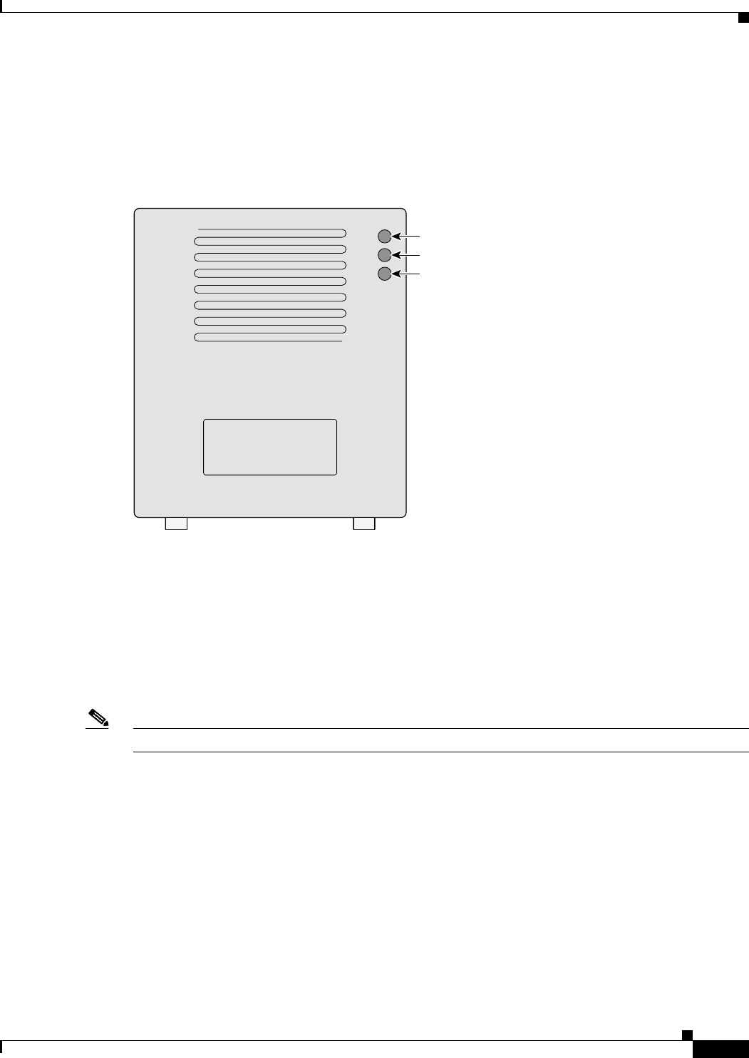
The three indicators on top of the access point report Ethernet activity, association status, and radio
activity as shown in Figure 1-1.
Figure 1-1 Indicators on the 1200 Series Access Point
•The Ethernet indicator signals Ethernet traffic on the wired LAN. This indicator blinks green when
a packet is received or transmitted over the Ethernet infrastructure. The indicator blinks red when
the Ethernet cable is not connected.
•The association status indicator signals operational status. Blinking green indicates that the access
point is operating normally but is not associated with any wireless client devices. Steady green
indicates that the access point is associated with at least one wireless client device.
•The radio indicator blinks green to indicate radio traffic activity. The light is normally off, but it
blinks green whenever a packet is received or transmitted over the access point radio.
Note The Radio and Status indicators are used for both 2.4-GHz and 5-GHz radio operation.
Ethernet
Status
Radio
74046
Draft Copy - CISCO CONFIDENTIAL
1-6
Cisco Aironet 1200 Series Access Point Hardware Installation Guide
OL-2155-02
Chapter 1 Overview
Key Features
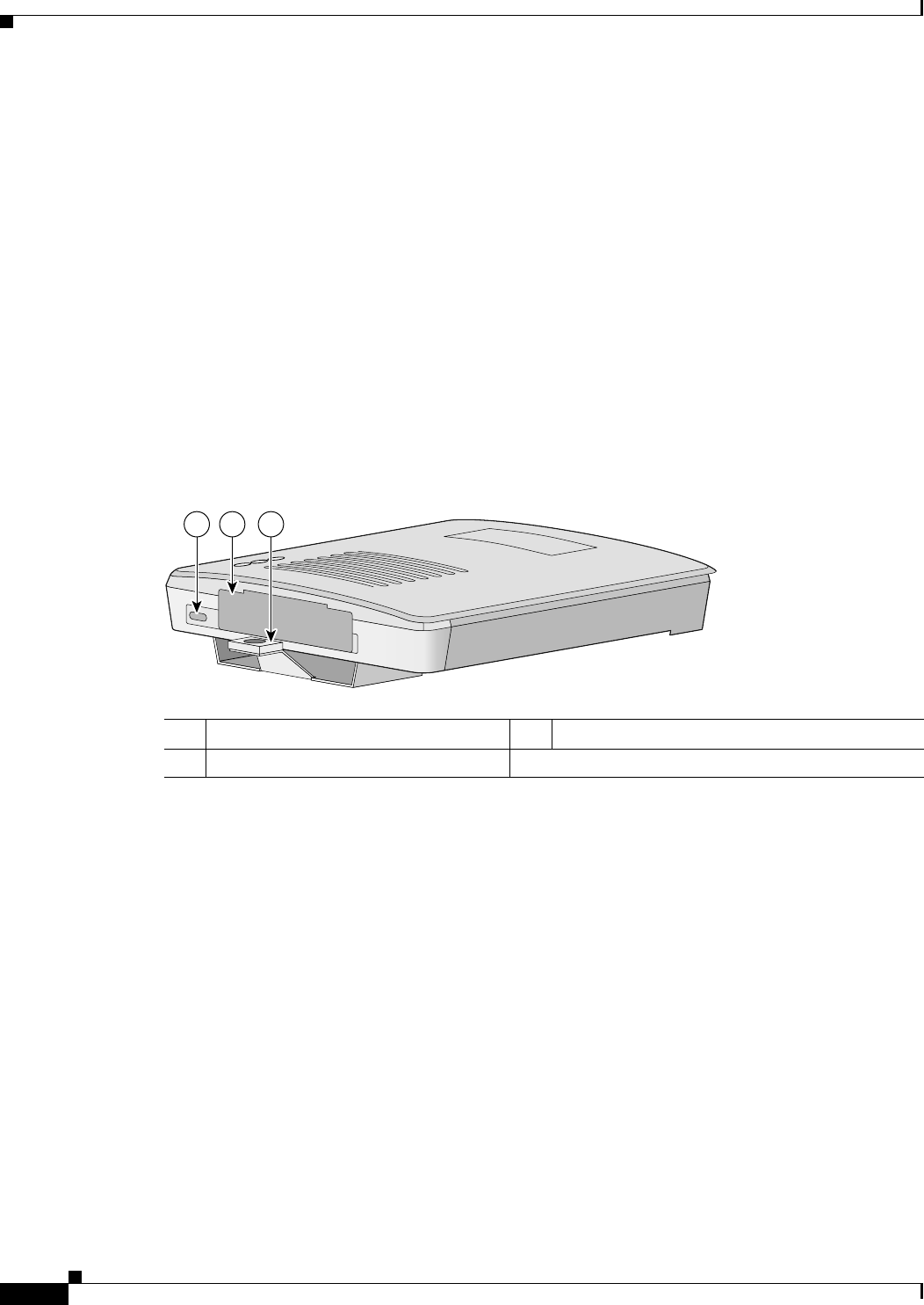
Security Lock Feature
The access point provides two methods of securing the access point to help prevent theft (see
Figure 1-2):
•Security hasp
•Security cable keyhole
The security hasp on the mounting bracket allows you to lock the access point to the bracket to make it
more secure. When the access point is properly installed on the mounting bracket, the holes in the
security hasps line up so you can install a padlock. Compatible padlocks are Master Lock models 120T
or 121T.
When using the security hasp with a lock, the access point is secured to the mounting bracket and the
mounting bracket screws along with the 2.4-GHz radio access cover are not accessible.
The security cable keyhole allows you to secure the access point using a standard security cable, such as
the security cables used on laptop computers.
Figure 1-2 Access Point Security Points
1Security cable keyhole 25-GHz module slot access cover
3Security hasp for padlock
21 3
74344
Draft Copy - CISCO CONFIDENTIAL
1-7
Cisco Aironet 1200 Series Access Point Hardware Installation Guide
OL-2155-02
Chapter 1 Overview
Network Configuration Examples
Network Configuration Examples
This section describes the access point’s role in three common wireless network configurations. The
access point’s default configuration is as a root unit on a wired LAN. The other two possible roles,
repeater unit and central unit in an all-wireless network, require specific changes to the default
configuration.
Note The following network configuration examples apply to both 2.4-GHz and 5-GHz wireless LANs.
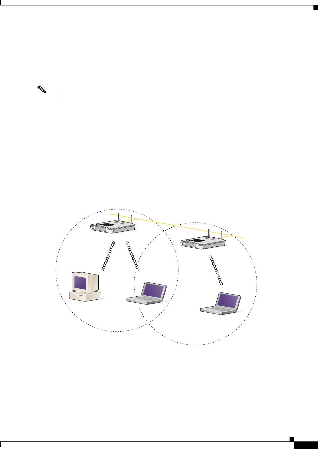
Root Unit on a Wired LAN
An access point connected directly to a wired LAN provides a connection point for wireless users. If
more than one access point is connected to the LAN, users can roam from one area of a facility to another
without losing their connection to the network. As users move out of range of one access point, they
automatically connect to the network (associate) through another access point. The roaming process is
seamless and transparent to the user. Figure 1-3 shows access points acting as root units on a wired LAN.
Figure 1-3 Access Points as Root Units on a Wired LAN
Access Point
(Root Unit)
Access Point
(Root Unit)
65999
Wired LAN
Draft Copy - CISCO CONFIDENTIAL
1-8
Cisco Aironet 1200 Series Access Point Hardware Installation Guide
OL-2155-02
Chapter 1 Overview
Network Configuration Examples
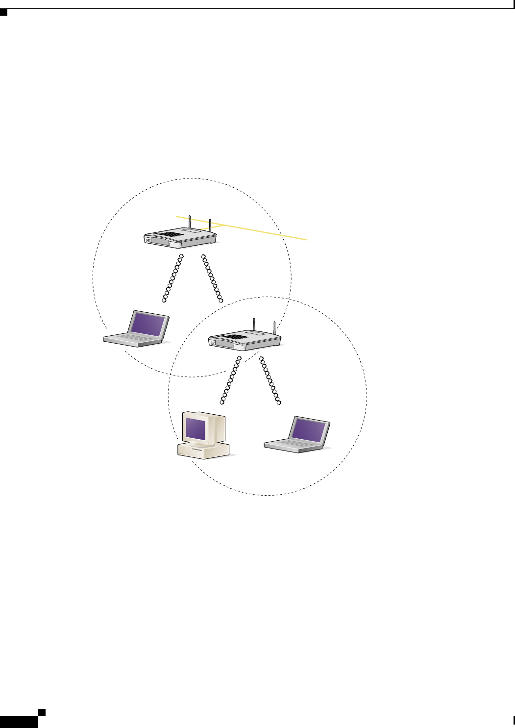
Repeater Unit That Extends Wireless Range
An access point can be configured as a stand alone repeater to extend the range of your infrastructure or
to overcome an obstacle that blocks radio communication. The repeater forwards traffic between
wireless users and the wired LAN by sending packets to either another repeater or to an access point
connected to the wired LAN. The data is sent through the route that provides the greatest performance
for the client. Figure 1-4 shows an access point acting as a repeater.
Figure 1-4 Access Point as Repeater
Access Point
(Root Unit)
Access Point
(Repeater)
66000
Wired LAN
Draft Copy - CISCO CONFIDENTIAL
1-9
Cisco Aironet 1200 Series Access Point Hardware Installation Guide
OL-2155-02
Chapter 1 Overview
Network Configuration Examples
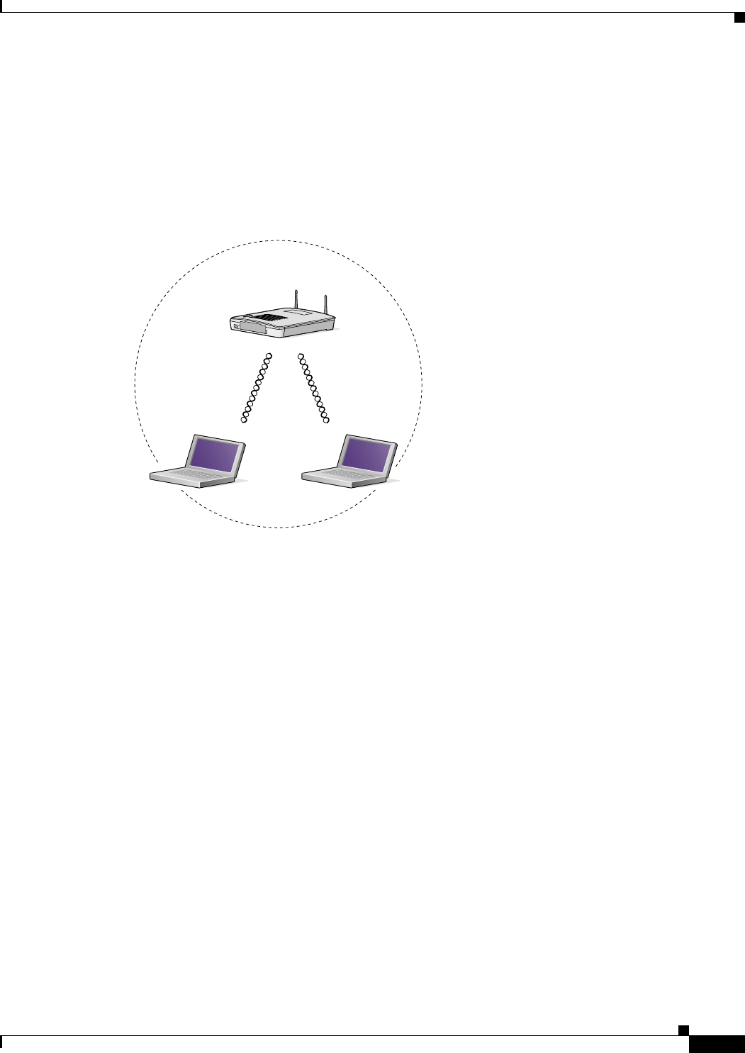
Central Unit in an All-Wireless Network
In an all-wireless network, an access point acts as a stand-alone root unit. The access point is not
attached to a wired LAN; it functions as a hub linking all stations together. The access point serves as
the focal point for communications, increasing the communication range of wireless users. Figure 1-5
shows an access point in an all-wireless network.
Figure 1-5 Access Point as Central Unit in All-Wireless Network
Access Point
(Root Unit)
65998

Draft Copy - CISCO CONFIDENTIAL
1-10
Cisco Aironet 1200 Series Access Point Hardware Installation Guide
OL-2155-02
Chapter 1 Overview
Access Point Specifications
Access Point Specifications
The access point specifications are listed in Table 1-1.
Table 1-1 Access Point Specifications
Category Access Point with 2.4-GHz Radio Access Point with 5-GHz Radio Module
Size 6.56 in. W x 7.23 in. D x 1.66 in. H
16.67 cm W x 18.36 cm D x 4.22 cm H With the 5-GHz antenna in the patch position:
6.56 in. W x 8.04 in. D x 2.21 in. H
16.67 cm W x 20.42 cm D x 5.61
Status Indicators Three indicators on the top panel: Ethernet traffic, status, and radio traffic
Connectors Back panel (left to right): reverse-TNC antenna connector; power connector (for plug-in AC power
module); RJ-45 connector for 10/100 BASE-T Ethernet connections; upside down RJ-45 connector
for serial connections; reverse-TNC antenna connector.
Front Panel: Card Bus connector used for the 5-GHz radio module.
Input Voltage 48VDC nominal. Operational up to 60VDC. Voltage higher than 60VDC can damage the unit.
Input Current With 2.4 GHz radio:
125 mA (typical) With 5-GHz radio:
TBD mA (typical)
With 2.4-GHz and 5-GHz radios
225 mA (typical)
The access point is capable of drawing 380 mA depending upon the current radios and future radios
installed in the unit.
Operating Temperature Access point:
–4 to 131oF (–20 to 55oC)
1200 series power injector:
32 to 104oF (0 to 40oC)
Access point:
–4 to 113oF (–20 to 45oC)
1200 series power injector:
32 to 104oF (0 to 40oC)
Storage Temperature –40 to 185oF (–40 to 85oC) –40 to 185oF (–40 to 85oC)
Weight Without mounting bracket:
1.6 lbs (0.73 kg) with 2.4-GHz radio
module
Without mounting bracket:
1.87 lbs (0.85 kg) with 5-Ghz radio module
1.97 lbs (0.89 kg) with 5-GHz radio module and
2.4-GHz radio
Power Output 100, 50, 30, 20, 5, or 1 mW
(Depending on the regulatory domain in
which the access point is installed)
40 mW (16 dBm)
20 mW (13 dBm)
10 mW (10 dBm)
5 mW (7 dBm)
Note These values are based on the FCC peak
measurement method as defined in
FCC 15.407 (A)(4)
Frequency 2.400 to 2.497 GHz
(Depending on the regulatory domain in
which the access point is installed)
UNII 1—5.15 to 5.25 GH
UNII 2—5.25 to 5.35 GHz
(Depending on the regulatory domain in which the
access point is installed)

Draft Copy - CISCO CONFIDENTIAL
1-11
Cisco Aironet 1200 Series Access Point Hardware Installation Guide
OL-2155-02
Chapter 1 Overview
Access Point Specifications
Range Indoor:
150 ft at 11 Mbps
350 ft at 1 Mbps
Outdoor:
800 ft at 11 Mbps
2000 ft at 1 Mbps
Indoor:
TBD ft at 6 Mbps
TBD ft at 54 Mbps
Outdoor:
TBD ft at 6 Mbps
TBD ft at 54 Mbps
Modulation Direct Sequence Spread Spectrum (DSSS) Orthogonal Frequency Division Multiplex (OFDM)
Data rates 1, 2, 5.5, and 11 Mbps 6, 9, 12, 18, 24, 36, 48, and 54 Mbps
Antenna A diversity system with two reverse-TNC
connectors (Cisco antennas are sold
separately).
A diversity system consisting of two integrated
omnidirectional and two integrated directional
antennas.
Compliance The 1200 series access point complies with UL 2043 for products installed in a building’s
environmental air handling spaces, such as above suspended ceilings.
Caution The 1200 series power injectors are not tested to UL 2043 and should not be placed in a
building’s environmental air space, such as above suspended ceilings.
Note If you plan to mount the access point in environmental air space using a 5-GHz radio, Cisco
recommends that you mount the access point horizontally with its antennas pointing down.
Doing so will result in the access point complying with regulatory requirements for
environmental air space with the 5-GHz radio installed.
Safety Designed to meet:
•UL 1950 Third Edition
•CSA 22.2 No. 950-95
•IEC 60950 Second Edition, including
Amendments 1-4 with all deviations
•EN 60950 Second Edition, including
Amendments 1-4
Designed to meet:
•UL 1950 Third Edition
•CSA 22.2 No. 950-95
•IEC 60950 Second Edition, including
Amendments 1-4 with all deviations
•EN 60950 Second Edition, including
Amendments 1-4
Radio Approvals FCC Part 15.247
Canada RSS-139-1, RSS-210
Japan Telec 33B
EN 300.328
FCC Part 15.407
Canada RSS-210
Japan ARIB STD-T71
EN 301.893
EMI and Susceptibility FCC Part 15.107 and 15.109 Class B
ICES-003 Class B (Canada)
EN 55022 B
AS/NZS 3548 Class B
VCCI Class B
EN 55024
EN 301.489-1
EN 301.489-17
RF Exposure OET-65C
RSS-102
ANSI C95.1
Table 1-1 Access Point Specifications (continued)
Category Access Point with 2.4-GHz Radio Access Point with 5-GHz Radio Module

Draft Copy - CISCO CONFIDENTIAL
1-12
Cisco Aironet 1200 Series Access Point Hardware Installation Guide
OL-2155-02
Chapter 1 Overview
Access Point Specifications

CHAPTER
2-1
Cisco Aironet 1200 Series Access Point Hardware Installation Guide
OL-2155-02
2
Installation
This chapter describes the setup of the access point and includes the following sections:
•Safety Information, page 2-2
•Warnings, page 2-3
•Installation Guidelines, page 2-4
•Unpacking the Access Point, page 2-6
•Before Beginning the Installation, page 2-7
•Installation Summary, page 2-8
•Connecting the 2.4-GHz Antennas, page 2-8
•Connecting the Ethernet and Power Cables, page 2-9

Draft Copy - CISCO CONFIDENTIAL
2-2
Cisco Aironet 1200 Series Access Point Hardware Installation Guide
OL-2155-02
Chapter 2 Installation
Safety Information
Safety Information
Follow the guidelines in this section to ensure proper operation and safe use of the access point.
FCC Safety Compliance Statement
The FCC, with its action in ET Docket 96-8, has adopted a safety standard for human exposure to RF
electromagnetic energy emitted by FCC-certified equipment. When used with approved Cisco Aironet
antennas, Cisco Aironet products meet the uncontrolled environmental limits found in OET-65 and ANSI
C95.1, 1991. Proper operation of this radio device according to the instructions in this publication will
result in user exposure substantially below the FCC recommended limits.
General Safety Guidelines
•Do not touch or move the antenna while the unit is transmitting or receiving.
•Do not hold any component containing a radio such that the antenna is very close to or touching any
exposed parts of the body, especially the face or eyes, while transmitting.
•Do not operate the radio or attempt to transmit data unless the antenna is connected; otherwise, the
radio may be damaged.
•Use in specific environments:
–
The use of wireless devices in hazardous locations is limited to the constraints posed by the
local codes, the national codes and the safety directors of such environments.
–
The use of wireless devices on airplanes is governed by the Federal Aviation Administration
(FAA).
–
The use of wireless devices in hospitals is restricted to the limits set forth by each hospital.
•Antenna use:
–
High-gain wall-mount or mast-mount antennas are designed to be professionally installed.
Please contact your professional installer, VAR, or antenna manufacturer for proper installation
requirements.

Draft Copy - CISCO CONFIDENTIAL
2-3
Cisco Aironet 1200 Series Access Point Hardware Installation Guide
OL-2155-02
Chapter 2 Installation
Warnings
Warnings
Translated versions of the following safety warnings are provided in Appendix A, “Translated Safety
Warnings.”
Warning
In order to comply with FCC radio frequency (RF) exposure limits, dipole antennas should be located
at a minimum of 7.9 inches (20 cm) or more from the body of all persons.
Warning
Do not operate your wireless network device near unshielded blasting caps or in an explosive
environment unless the device has been modified to be especially qualified for such use.
Warning
Do not locate the antenna near overhead power lines or other electric light or power circuits, or
where it can come into contact with such circuits. When installing the antenna, take extreme care
not to come into contact with such circuits, as they may cause serious injury or death. For proper
installation and grounding of the antenna, please refer to national and local codes (e.g. U.S.:NFPA 70,
National Electrical Code, Article 810, in Canada: Canadian Electrical Code, Section 54).
Warning
Do not work on the system or connect or disconnect cables during periods of lightning activity.
Warning
Read the installation instructions before you connect the system to its power source.
Warning
This product relies on the building's installation for short-circuit (overcurrent) protection. Ensure that
a fuse or circuit breaker no larger than 120 VAC, 15A U.S. (240 VAC, 10A international) is used on the
phase conductors (all current-carrying conductors).
Draft Copy - CISCO CONFIDENTIAL
2-4
Cisco Aironet 1200 Series Access Point Hardware Installation Guide
OL-2155-02
Chapter 2 Installation
Installation Guidelines
Installation Guidelines
This section describes things to keep in mind when installing your access point. Sections include:
•Basic Guidelines
•Installation Above Suspended Ceilings
•Coverage Options
•Site Surveys
Basic Guidelines
Because the access point is a radio device, it is susceptible to common causes of interference that can
reduce throughput and range. Follow these basic guidelines to ensure the best possible performance:
•Install the access point in an area where large steel structures such as shelving units, bookcases, and
filing cabinets do not obstruct radio signals to and from the access point.
•Install the access point away from microwave ovens. Microwave ovens operate on the same
frequency as the access point and can cause signal interference.
Installation Above Suspended Ceilings
The access point uses a metal enclosure having adequate fire resistance and low smoke-producing
characteristics suitable for operation in a building’s environmental air space in accordance with
Section 300-22(c) of the NEC, such as above suspended ceilings. For mounting instructions refer to
Chapter 4, “Mounting Instructions.”
Caution The 1200 series power injectors are not tested to UL 2043 and should not be placed in a building’s
environmental air space, such as above suspended ceilings.
Note If you plan to mount the access point in environmental air space using a 5-GHz radio, Cisco recommends
that you mount the access point horizontally with its antennas pointing down. Doing so will result in the
access point complying with regulatory requirements for environmental air space with the 5-GHz radio
installed.
Draft Copy - CISCO CONFIDENTIAL
2-5
Cisco Aironet 1200 Series Access Point Hardware Installation Guide
OL-2155-02
Chapter 2 Installation
Installation Guidelines
Coverage Options
The network architecture options of wireless stations and access points provide for a variety of coverage
alternatives and flexibility. The network can be designed to provide a wide coverage area with minimal
overlap or a narrow coverage area with heavy overlap. A narrow coverage area with heavy overlap
improves network performance and protection against downtime if a component fails.
Note The following coverage options apply to both 2.4-GHz and 5-GHz wireless LANs.
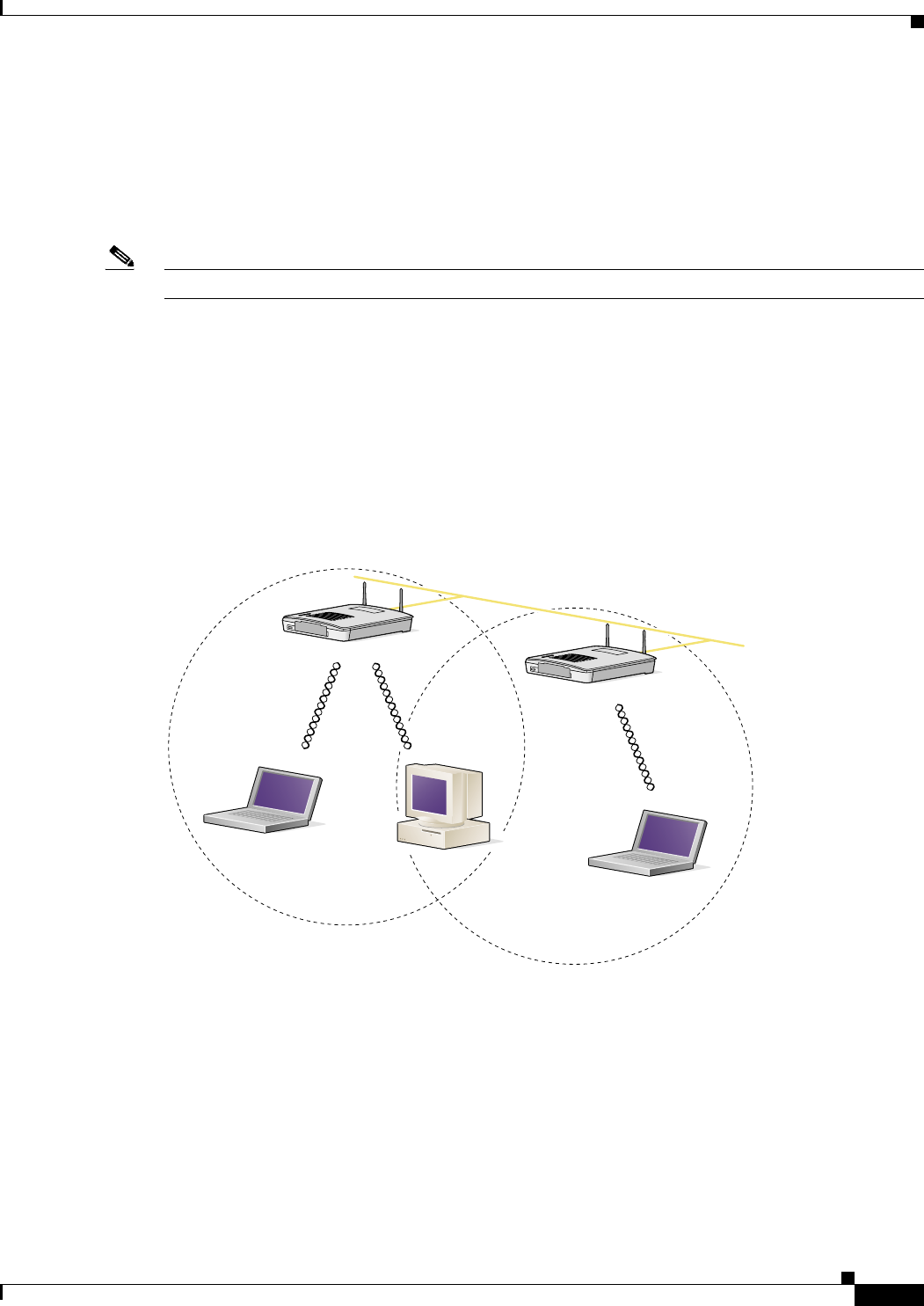
Minimal Overlap Coverage Option
By arranging the access points so that the overlap in a coverage area is minimized, a large area can be
covered with minimal cost (see Figure 2-1). The total bandwidth available to each wireless client device
depends on the amount of data each mobile station needs to transfer and the number of stations located
in each cell. Seamless roaming is supported as a client device moves in and out of range of each access
point, thereby maintaining a constant connection to the wired LAN. Each device in the radio network
must be configured with the same SSID to provide roaming capability.
Figure 2-1 Minimal Overlap Coverage Option
Heavy Overlap Coverage Option
By arranging the access points so the overlap in coverage area is nearly maximized, a large number of
mobile stations can be supported in the same wireless infrastructure. However, devices in overlapping
coverage areas on the same frequency will detect adjacent cell traffic and delay transmissions that would
cause collisions. This configuration reduces the aggregate radio system throughput. Heavy cell overlap
is not recommended for maximum system throughput.
74001
Wired LAN

Draft Copy - CISCO CONFIDENTIAL
2-6
Cisco Aironet 1200 Series Access Point Hardware Installation Guide
OL-2155-02
Chapter 2 Installation
Unpacking the Access Point
Because of the redundancy in coverage overlap, network access is not lost if an access point fails. Upon
failure of the access point, the station automatically roams to an operational access point. With this
architecture, each device in the RF network must be configured with the same SSID to provide the
roaming capability.
Site Surveys
Because of differences in component configuration, placement, and physical environment, every
network application is a unique installation. Before installing multiple access points, you should perform
a site survey to determine the optimum utilization of networking components and to maximize range,
coverage, and network performance.
When supporting dual mode 2.4-GHz and 5-GHz operation, you may have to perform a site survey for
each of the operating frequencies.
Consider the following operating and environmental conditions when performing a site survey:
•Frequency—The radio coverage area for the 5-GHz radio is less than the coverage area for the
2.4-GHz radio.
•Single- and dual-band operation—When supporting both single and dual band access points, you
should perform a site survey for each of the operating frequencies.
•Data rates—Sensitivity and range are inversely proportional to data bit rates. The maximum radio
range is achieved at the lowest workable data rate. A decrease in receiver threshold sensitivity occurs
as the radio data increases.
•Antenna type and placement—Proper antenna configuration is a critical factor in maximizing radio
range. As a general rule, range increases in proportion to antenna height.
•Physical environment—Clear or open areas provide better radio range than closed or filled areas.
Also, the less cluttered the work environment, the greater the range.
•Obstructions—A physical obstruction such as metal shelving or a steel pillar can hinder
performance of wireless devices. Avoid locating the devices in a location where there is a metal
barrier between the sending and receiving antennas.
•Building materials—Radio penetration is greatly influenced by the building material used in
construction. For example, drywall construction allows greater range than concrete blocks. Metal or
steel construction is a barrier to radio signals.
Unpacking the Access Point
Follow these steps to unpack the access point:
Step 1 Open the shipping container and carefully remove the contents.
Step 2 Return all packing materials to the shipping container and save it.
Step 3 Ensure that all items listed in the “Package Contents” section are included in the shipment. Check each
item for damage. If any item is damaged or missing, notify your authorized Cisco sales representative.
Draft Copy - CISCO CONFIDENTIAL
2-7
Cisco Aironet 1200 Series Access Point Hardware Installation Guide
OL-2155-02
Chapter 2 Installation
Before Beginning the Installation
Package Contents
Each access point package contains the following items:
•Cisco Aironet 1200 Series Access Point
•Cisco Aironet 1200 Series Power Module (Universal power supply)
•Quick Start Guide: Cisco Aironet 1200 Series Access Point
•Cisco product registration and Cisco documentation feedback cards
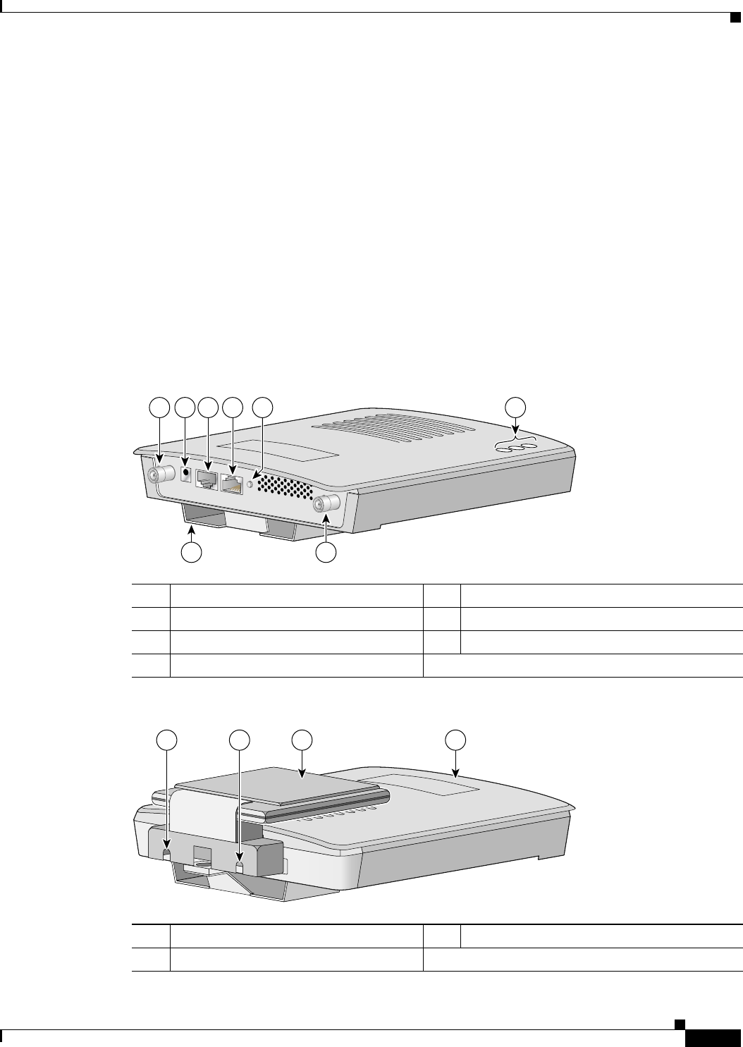
Before Beginning the Installation
Before you begin the installation process, please refer to Figure 2-2 and Figure 2-3 to become familiar
with the access point’s layout, connectors, and 5-GHz module location.
Figure 2-2 Access Point Layout and Connectors
Figure 2-3 5-GHz Radio Module
12.4-GHz antenna connectors 5Mode button (possible future feature)
248VDC power port 6Status LEDs
3Ethernet port (RJ-45) 7Mounting bracket
4Console port (RJ-45)
1 2 3 4 6
7 1
5
65847
15-GHz radio module mounting screws 25-GHz radio module antenna (patch position)
3Access point
74631
1 1 2 3

Draft Copy - CISCO CONFIDENTIAL
2-8
Cisco Aironet 1200 Series Access Point Hardware Installation Guide
OL-2155-02
Chapter 2 Installation
Installation Summary
Installation Summary
During the installation of the access point, you will perform the following operations:
•Connect a single antenna or dual diversity antennas (refer to the “Connecting the 2.4-GHz
Antennas” section on page 2-8).
•Connect Ethernet and power cables (refer to the “Connecting the Ethernet and Power Cables”
section on page 2-9).
•Configure basic settings (refer to Chapter 3, “Basic Configuration”).
•Mount the access point to a ceiling or wall. For additional information, refer to Chapter 4,
“Mounting Instructions.”
•Configure security and other access point options. For additional information, refer to the Cisco
Aironet 1200 Series Access Point Software Configuration Guide.
Connecting the 2.4-GHz Antennas
The access point supports a single antenna or dual diversity antennas. Two R-TNC antenna connectors
are provided on the back of the unit for the 2.4-GHz radio.
If you are using a Cisco Aironet 2 dBi antenna, follow the steps below:
Step 1 Attach an antenna to the Right/Primary 2.4-GHz (R-TNC) antenna connector on the back of the access
point and tighten hand tight. If you are using two antennas for diversity coverage, attach the second
antenna to the Left 2.4-GHz (R-TNC) antenna connector.
Step 2 Orient the antenna depending on how you intend to mount the access point.
•On a table or desk, orient the antenna straight up.
•On a vertical surface, such as a wall, orient the antenna straight up.
•On a ceiling, orient the antenna straight down.
If you are using another Cisco Aironet antenna, refer to the instructions that came with your antenna.
Draft Copy - CISCO CONFIDENTIAL
2-9
Cisco Aironet 1200 Series Access Point Hardware Installation Guide
OL-2155-02
Chapter 2 Installation
Connecting the Ethernet and Power Cables
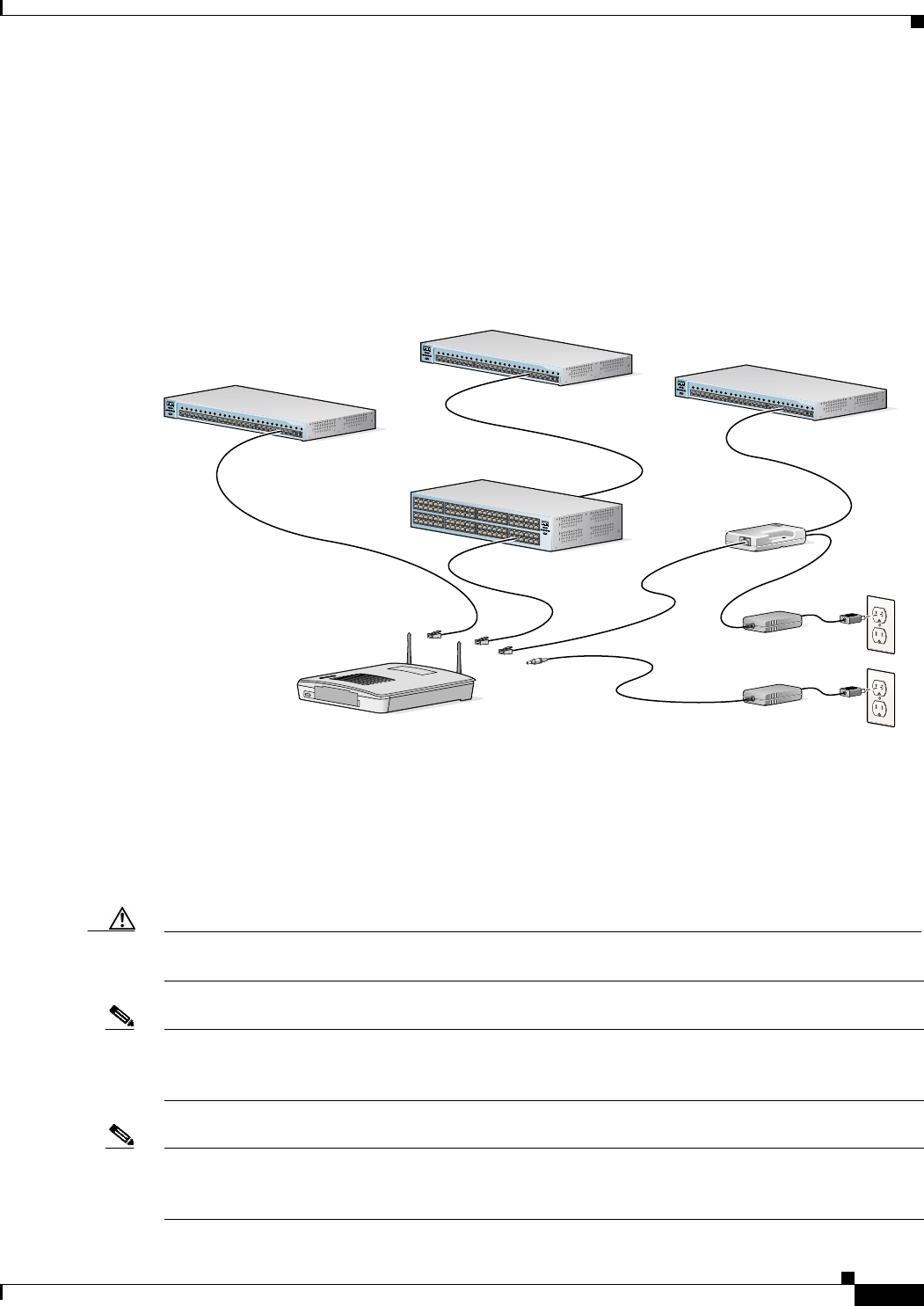
Connecting the Ethernet and Power Cables
The access point receives power through the Ethernet cable or a 1200 series power module (universal
power supply). Figure 2-4 shows the power options for the access point.
Figure 2-4 Access Point Power Options
The access point power options are listed below:
•A switch with inline power, such as a Cisco Catalyst 3524-PWR-XL Switch
•An inline power patch panel, such as a Cisco Catalyst Inline Power Patch Panel
•A 1200 series power injector
•A 1200 series power module (Universal power supply)
Caution The 1200 series power injectors are not tested to UL 2043 and should not be placed in a building’s
environmental air space, such as above suspended ceilings.
Note If you use in-line power from a switch or patch panel, do not connect the 1200 series power module to
the access point. Using two power sources on the access point might cause the switch or patch panel to
shut down the port to which the access point is connected.
Note If you need to use a power module or power injector to power the access point, you must use the
1200 series power module or power injector. The 350 series power module and power injector are not
compatible with the 1200 series access point.
Power
cord
Universal
power supply
SYSTRPS
DUPLX
MODE
SPEED
UTILSTAT
12345678910 11 12 13 14 15 16 17 18 19 20 21 22 23 24 23 24
10Base-T / 100Base-TX 100Base-FX
Catalyst 2950
SERIES
SYST RPS
DUPLX
MODE
SPEED
UTIL
STAT
12345678910 11 12 13 14 15 16 17 18 19 20 21 22 23 24 23 24
10Base-T / 100Base-TX 100Base-FX
Catalyst 2950
SERIES
SYST RPS
DUPLX
MODE
SPEED
UTIL
STAT
12345678910 11 12 13 14 15 16 17 18 19 20 21 22 23 24 23 24
10Base-T / 100Base-TX 100Base-FX
Catalyst 2950
SERIES
SYSTRPS
DUPLX
MODE
SPEED
UTIL
STAT
TO
AP/ BRIDGE
TO
NETWORK
Switch with
inline power
Power injector
Access Point
Switch
(without inline power) Switch
(without inline power)
Inline Power
Patch Panel
Option 1 Option 2 Option 3
74164

Draft Copy - CISCO CONFIDENTIAL
2-10
Cisco Aironet 1200 Series Access Point Hardware Installation Guide
OL-2155-02
Chapter 2 Installation
Connecting the Ethernet and Power Cables
Note Only the 1200 series power injector and the 1200 series power module can support simultaneous
operation of both the 2.4-GHz and the 5.0-GHz radios in the access point.
Note Both the Ethernet and console ports use RJ-45 connectors. Be careful to avoid accidently connecting the
serial cable to the Ethernet port connector.
Follow these steps to connect the Ethernet and power cables to the access point:
Step 1 If you are using in-line power from a switch or patch panel, connect an Ethernet cable from the access
point to the device that supplies power.
Step 2 If you are using in-line power from a 1200 series power injector, follow these additional steps:
a. Connect an Ethernet cable from the access point into the end of the 1200 series power injector
labeled To AP/Bridge.
b. Connect an Ethernet cable from the end of the 1200 series power injector labeled To Network to the
your 10/100 Ethernet LAN.
c. Plug the female end of the AC power cord into the 1200 series power module (Universal power
supply) and plug the male end into a suitable AC power receptacle.
Step 3 If you are using a 1200 series power module, follow these additional steps:
a. Connect an Ethernet cable from the access point to your 10/100 Ethernet LAN.
b. Plug the female end of the power cord into the 1200 series power module (Universal power supply)
and plug the male end into a suitable power receptacle.
c. Plug the power connector into the back of the access point.
At startup, all three LEDs on the top of the access point slowly blink amber, red, and green in sequence;
the sequence takes a few minutes to complete. During normal operation, the LEDs blink green. Refer to
Chapter 7, “Troubleshooting,” for LED descriptions.
Refer to Chapter 3, “Basic Configuration,” to assign basic settings to the access point.

CHAPTER
3-1
Cisco Aironet 1200 Series Access Point Hardware Installation Guide
OL-2155-02
3
Basic Configuration
This chapter describes the initial configuration of the access point using the Internet browser-based
management system and the serial interface. You can also reach the management system through a Telnet
session. Consult the Cisco Aironet 1200 Series Access Point Software Configuration Guide for complete
instructions on using these interfaces.
This chapter includes the following sections:
•Before You Start, page 3-2
•Summary of Configuration Steps, page 3-2
•Using the IP Setup Utility, page 3-3
•Entering Basic Settings, page 3-6
•Default Basic Settings, page 3-13

Draft Copy - CISCO CONFIDENTIAL
3-2
Cisco Aironet 1200 Series Access Point Hardware Installation Guide
OL-2155-02
Chapter 3 Basic Configuration
Before You Start
Before You Start
Before configuring the access point, you need to obtain the following information (possibly from your
network administrator):
•The service set identifier (SSID) for the access point. If dual-band radio operation is supported,
different SSIDs for 2.4 GHz and 5-GHz operation may be used.
•A system name for the access point. The name should describe the location or principal users of the
access point. The access point default system name is AIR-AP1200-xxxxxx, where xxxxxx is the last
6 digits of the access point MAC address.
•If your network does not use DHCP or BOOTP to assign IP addresses, you need the following:
–
IP address for the access point
–
IP address for the default gateway
–
IP subnet mask for the access point
•The access point’s MAC address, which is printed on the label on the bottom of the access point.
•Security settings for the wireless network, such as WEP, LEAP, and MIC settings. Different security
settings may be used for the 2.4-GHz and 5-GHz wireless LANS. For additional information on
configuring the access point security settings, refer to the Cisco Aironet 1200 Series Access Point
Software Configuration Guide.
Summary of Configuration Steps
You use the Express Setup page to assign basic settings to the access point. For instructions on setting
up security, filtering, and other access point features, refer to the Cisco Aironet 1200 Series Access Point
Software Configuration Guide.
You will follow these general steps to enter the access point’s basic settings:
1. Connect the Ethernet and power cables to the access point. For instructions refer to the “Connecting
the Ethernet and Power Cables” section on page 2-8.
2. Use an Internet browser to open the access point’s management system by browsing to the access
point’s IP address or use a terminal emulator and the serial console port.
If your network uses a DHCP server and you are using a Windows operating system (Windows 95,
98, NT, 2000, ME, or XP), you can use the IP Setup Utility (IPSU) to find the access point’s
DHCP-assigned IP address. For other operating systems, you must use the serial console port. For
additional information on IPSU, refer to the “Using the IP Setup Utility” section on page 3-3.
To use the console port, you must connect an RJ-45 to DB-9 serial cable (refer to Appendix C,
“Console Cable Pinouts”) to your computer’s COM port and to the console port on the back of the
access point and use a terminal emulator to open the management system. For additional information
on using the console port, refer to the “Using a Terminal Emulator” section on page 3-9.
3. Enter basic settings on the Express Setup page as described in the “Entering Basic Settings” section
on page 3-6.
4. Mount the access point to the ceiling or wall. For mounting instructions, refer to Chapter 4,
“Mounting Instructions.”
5. Enter security and other access point option settings. For additional information, refer to the Cisco
Aironet 1200 Series Access Point Software Configuration Guide.

Draft Copy - CISCO CONFIDENTIAL
3-3
Cisco Aironet 1200 Series Access Point Hardware Installation Guide
OL-2155-02
Chapter 3 Basic Configuration
Using the IP Setup Utility
Using the IP Setup Utility
The IP Setup utility (IPSU) allows you to find the access point’s IP address when it has been assigned
by a DHCP server. You can also use IPSU to set the access point’s IP address and SSID if they have not
been changed from the default settings.
Note IPSU can be used only on the following operating systems: Windows 95, 98, NT, 2000, ME, or XP. For
other operating systems, you must use the access point console port and a terminal emulator program to
configure the access point.
The sections below explain how to install the utility, how to use it to find the access point’s IP address,
and how to use it to set the IP address and the SSID.
Obtaining and Installing IPSU
IPSU is available on the Cisco web site. Follow these steps to obtain and install IPSU:
Step 1 Use your Internet browser to access the Cisco Software Center at the following URL:
http://www.cisco.com/public/sw-center/sw-wireless.shtml
Step 2 Locate the utilities section and click on the individual files link for Windows.
Step 3 Click IPSUvxxxxx.exe. The vxxxxxx identifies the software package version number.
Step 4 Read and accept the terms and conditions of the Software License Agreement.
Step 5 Download and save the file to a temporary directory on your hard drive and then exit the Internet browser.
Step 6 Double-click IPSUvxxxxxx.exe in the temporary directory to expand the file.
Step 7 Double-click Setup.exe and follow the steps provided by the installation wizard to install IPSU.
The IPSU icon appears on your computer desktop.
Finding the Access Point’s IP Address
If your access point receives an IP address from a DHCP server, you can use IPSU to find its IP address.
You must run IPSU from a computer on the same subnetwork as the access point. Follow these steps to
find the access point’s IP address:
Step 1 Double-click the IPSU icon on your computer desktop to start the utility.
Draft Copy - CISCO CONFIDENTIAL
3-4
Cisco Aironet 1200 Series Access Point Hardware Installation Guide
OL-2155-02
Chapter 3 Basic Configuration
Using the IP Setup Utility
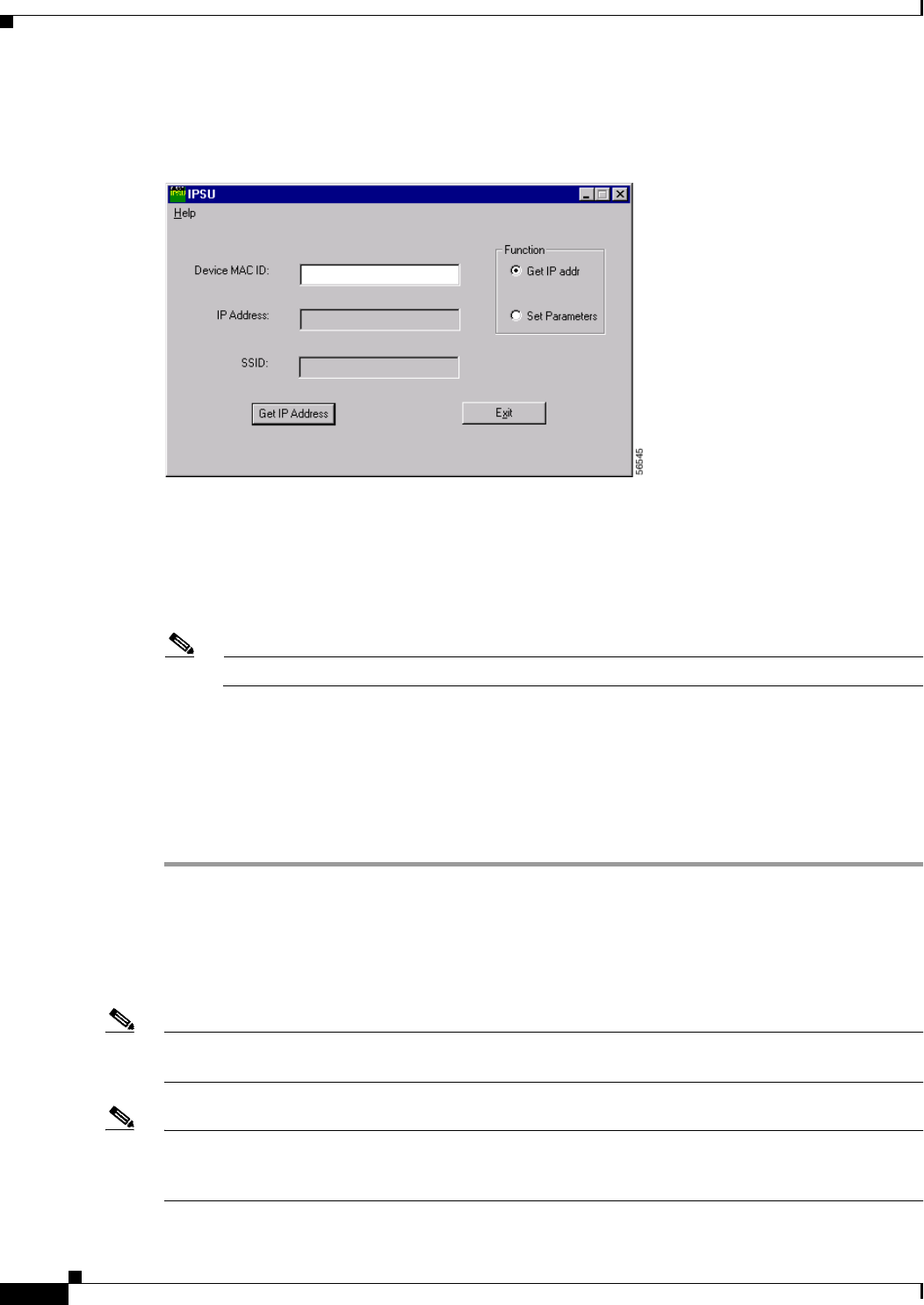
The IPSU screen appears (see Figure 3-1).
Figure 3-1 IPSU Get IP Address Screen
Step 2 When the utility window opens, make sure the Get IP addr radio button in the Function box is selected.
Step 3 Enter the access point’s MAC address in the Device MAC ID field. The access point’s MAC address is
printed on the label on the bottom of the unit. It should contain six pairs of hexadecimal digits. Your
access point’s MAC address might look like the following example:
000164xxxxxx
Note The MAC address field is not case-sensitive.
Step 4 Click Get IP Address.
Step 5 When the access point’s IP address appears in the IP Address field, write it down.
If IPSU reports that the IP address is 10.0.0.1, the default IP address, then the access point did not receive
a DHCP-assigned IP address. To change the access point IP address using IPSU, refer to the “Setting the
Access Point’s IP Address and SSID” section on page 3-4. To change the access point IP address using
the console port, refer to the “Assigning Basic Settings” section on page 3-9.
Setting the Access Point’s IP Address and SSID
You can use IPSU to change the default IP address and SSID of the access point.
Note The computer you use to assign an IP address to the access point must have an IP address of its own and
be located on the same subnet as the access point.
Note IPSU can change the access point’s IP address and SSID only from their default settings. After the IP
address and SSID have been changed, IPSU cannot change them again (see the “Using an Internet
browser” section on page 3-6 or the “Using a Terminal Emulator” section on page 3-9.)
Draft Copy - CISCO CONFIDENTIAL
3-5
Cisco Aironet 1200 Series Access Point Hardware Installation Guide
OL-2155-02
Chapter 3 Basic Configuration
Using the IP Setup Utility
Note When using IPSU to change the SSID in a dual-mode access point, the SSIDs for both radios are changed
to the new setting.
Follow these steps to assign an IP address and an SSID to the access point:
Step 1 Double-click the IPSU icon on your computer desktop to start the utility.
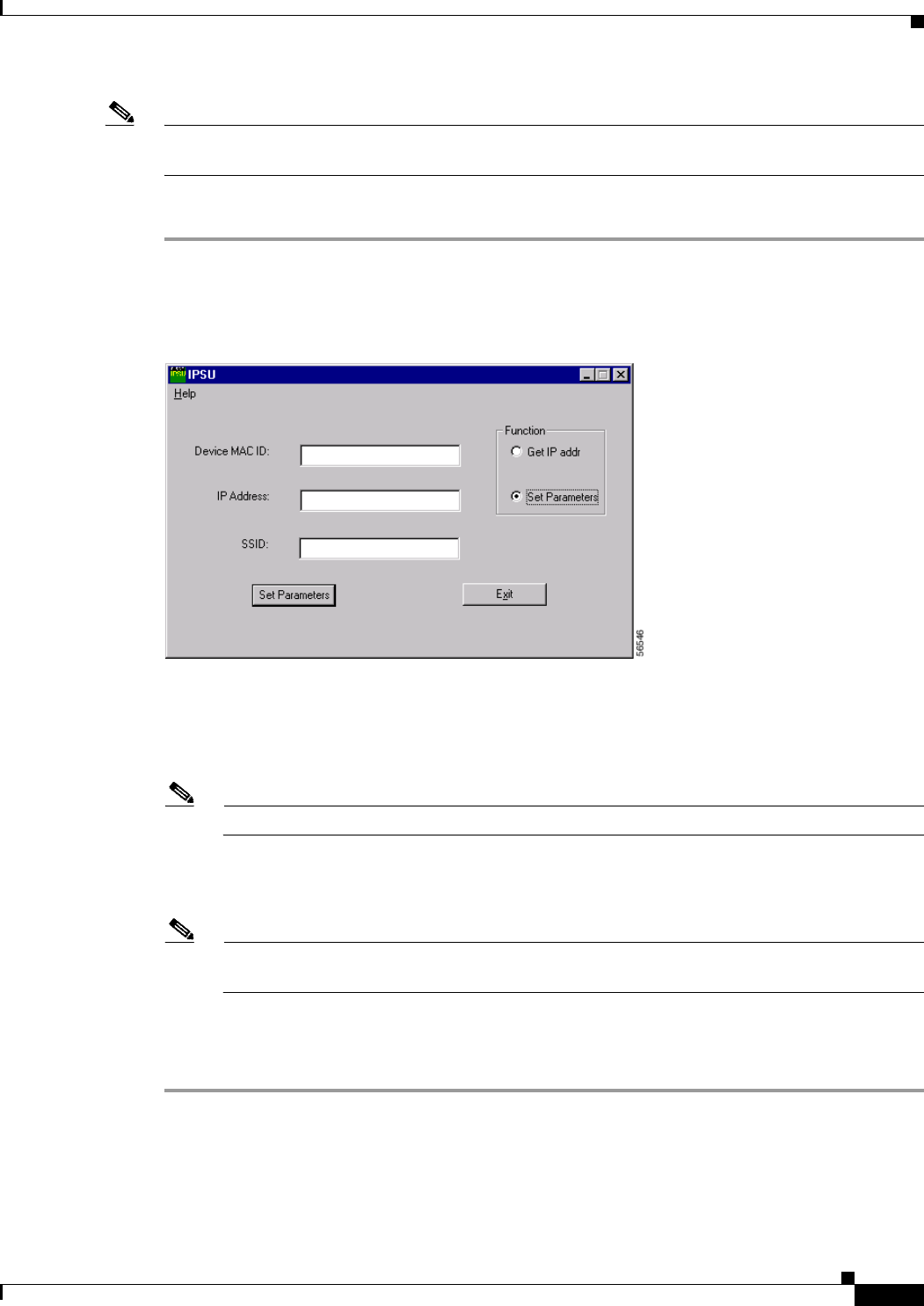
Step 2 Click the Set Parameters radio button in the Function box (see Figure 3-2).
Figure 3-2 IPSU Set Parameters Screen
Step 3 Enter the access point’s MAC address in the Device MAC ID field. The access point’s MAC address is
printed on the label on the bottom of the unit. It should contain six pairs of hexadecimal digits. Your
access point’s MAC address might look like the following example:
004096xxxxxx
Note The MAC address field is not case-sensitive.
Step 4 Enter the IP address you want to assign to the access point in the IP Address field.
Step 5 Enter the SSID you want to assign to the access point in the SSID field.
Note You cannot set the SSID without also setting the IP address. However, you can set the IP address
without setting the SSID.
Step 6 Click Set Parameters to change the access point’s IP address and SSID settings.
Step 7 Click Exit to exit IPSU.
Draft Copy - CISCO CONFIDENTIAL
3-6
Cisco Aironet 1200 Series Access Point Hardware Installation Guide
OL-2155-02
Chapter 3 Basic Configuration
Entering Basic Settings
Entering Basic Settings
You can open the access point’s management system through your Internet browser or through the access
point’s console port using a terminal emulator. Each method is described in this section.
Using an Internet browser
Follow these steps to enter basic settings with an Internet browser:
Step 1 Enter or paste your access point’s IP address in the browser’s address or location field; if you are using
Netscape, the field is labeled Netsite or Location; if you are using Microsoft Internet Explorer, the field
is labeled Address. Press Enter.
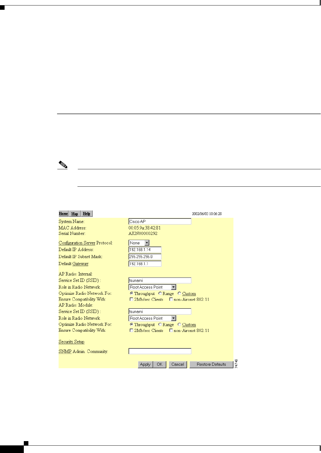
Step 2 When the access point’s Summary Status page appears, click Setup. When the Setup page appears, click
Express Setup. The Express Setup screen appears (Figure 3-3).
Note If the access point is new and its factory configuration has not been changed, the Express Setup
screen appears instead of the Summary Status screen when you first browse to the access point.
Figure 3-3 Express Setup Screen
Step 3 Enter a system name for the access point in the System Name field. A descriptive system name makes it
easy to identify the access point on your network. The default system name is AIR-AP1200-xxxxxx,
where xxxxxx is the last 6 digits of the access point MAC address.

Draft Copy - CISCO CONFIDENTIAL
3-7
Cisco Aironet 1200 Series Access Point Hardware Installation Guide
OL-2155-02
Chapter 3 Basic Configuration
Entering Basic Settings
Step 4 Select a configuration server protocol from the Configuration Server Protocol drop-down arrow menu.
The configuration server protocol you select should match your network’s method of IP address
assignment. The Configuration Server link takes you to the Boot Server Setup page, which you use to
configure the access point to work with your network’s BOOTP or DHCP servers for automatic
assignment of IP addresses.
The Configuration Server Protocol drop-down menu options include:
•None—Your network does not have an automatic system for IP address assignment.
•BOOTP—With Bootstrap Protocol, IP addresses are assigned based on MAC addresses.
•DHCP—With Dynamic Host Configuration Protocol, IP addresses are “leased” for predetermined
periods of time.
Step 5 Enter an IP address in the Default IP address field.
•If DHCP is not enabled, the IP address entered is the access point’s static IP address.
•If DHCP or BOOTP is enabled, the address you enter in this field provides the IP address only when
no server responds with an IP address for the access point.
Step 6 Enter an IP subnet mask in the Default IP Subnet Mask field to identify the subnetwork so the access
point’s IP address can be recognized on the LAN.
•If DHCP or BOOTP is not enabled, this field is the subnet mask.
•If DHCP or BOOTP is enabled, this field provides the subnet mask only when no server responds to
the access point’s DHCP or BOOTP request.
Step 7 Enter the IP address of your default internet gateway in the Default Gateway field. The entry
255.255.255.255 indicates no gateway. Clicking the Gateway link takes you to the Routing Setup page,
which you use to configure the access point to communicate with the IP network routing system.
Step 8 For the AP Radio: Internal (2.4-GHz) settings, perform the following steps:
Note The radio parameters can be different for the 2.4-GHz and 5-GHz wireless LANs.
a. Enter an SSID for the access point’s 2.4-GHz wireless LAN in the Radio Service Set ID (SSID)
field. The SSID is a unique identifier that client devices use to associate with the access point. The
SSID can be any alphanumeric entry from 2 to 32 characters long.
b. Select a network role for the access point from the Role in Radio Network drop-down arrow. The
menu contains the following options:
–
Root Access Point—A wireless LAN transceiver that connects an Ethernet network with
wireless client stations. Use this setting if the access point will be connected to the wired LAN.
–
Repeater Access Point—An access point that transfers data between a client and another access
point. Use this setting for access points not connected to the wired LAN.
–
Site Survey Client—A station with a wireless connection to an access point. Use this setting for
diagnostics, such as when you need to test the access point by having it communicate with
another access point.

Draft Copy - CISCO CONFIDENTIAL
3-8
Cisco Aironet 1200 Series Access Point Hardware Installation Guide
OL-2155-02
Chapter 3 Basic Configuration
Entering Basic Settings
c. Select an Optimize Radio Network For option to assign either preconfigured settings or customized
settings for the access point radio:
–
Throughput—Maximizes the data volume handled by the access point but might reduce the
access point’s range.
–
Range—Maximizes the access point’s range but might reduce throughput.
–
Custom—The access point uses the settings you enter on the AP Radio Hardware page. Click
the Custom link to go to the AP Radio Hardware page.
d. To automatically configure the access point to be compatible with other devices on your wireless
LAN, select an Ensure Compatibility With option:
–
2-Mbps clients—Select this setting if your network contains Cisco Aironet devices that operate
at 2 Mbps.
–
non-Aironet 802.11—Select this setting if there are non-Cisco Aironet devices on your wireless
LAN.
Step 9 For the AP Radio: Module (5-GHz) settings, perform the following steps:
Note The radio parameters can be different for the 2.4-GHz and 5-GHz wireless LANs.
a. Enter an SSID for the access point’s 5-GHz wireless LAN in the Radio Service Set ID (SSID) field.
The SSID is a unique identifier that client devices use to associate with the access point. The SSID
can be any alphanumeric entry from 2 to 32 characters long.
b. Select a network role for the access point from the Role in Radio Network drop-down arrow. The
menu contains the following options:
–
Root Access Point—A wireless LAN transceiver that connects an Ethernet network with
wireless client stations. Use this setting if the access point will be connected to the wired LAN.
–
Repeater Access Point—An access point that transfers data between a client and another access
point. Use this setting for access points not connected to the wired LAN.
–
Site Survey Client—A station with a wireless connection to an access point. Use this setting for
diagnostics, such as when you need to test the access point by having it communicate with
another access point.
c. Select an Optimize Radio Network For option to assign either preconfigured settings or customized
settings for the access point radio:
–
Throughput—Maximizes the data volume handled by the access point but might reduce the
access point’s range.
–
Range—Maximizes the access point’s range but might reduce throughput.
–
Custom—The access point uses the settings you enter on the AP Radio Hardware page. Click
the Custom link to go to the AP Radio Hardware page.
Step 10 To use Simplified Network Management Protocol (SNMP), enter a community name in the SNMP
Admin. Community field. This name automatically appears in the list of users authorized to view and
make changes to the access point’s management system. Click the SNMP link to go to the SNMP Setup
page, where you can edit other SNMP settings.
You can define other SNMP communities with User Management (for additional information refer to the
Cisco Aironet 1200 Series Access Point Software Configuration Guide).
Step 11 Click OK to set your configuration changes and the Setup page appears. Your basic configuration is
complete, you can close your internet browser.

Draft Copy - CISCO CONFIDENTIAL
3-9
Cisco Aironet 1200 Series Access Point Hardware Installation Guide
OL-2155-02
Chapter 3 Basic Configuration
Entering Basic Settings
For additional information on security options, refer to the Cisco Aironet 1200 Series Access Point
Software Configuration Guide.
Using a Terminal Emulator
This section provides instructions for using the console port and Microsoft’s HyperTerminal to set basic
access point settings; other terminal emulator programs are similar. Typically, you would use the serial
interface when the access point is initially being configured with basic settings and is easily accessible.
When the access point is initially configured and mounted in an elevated operating location, the browser
interface is more convenient to use to make access point configuration changes.
Selecting Pages and Settings
With the serial interface, when you enter names and settings that appear in brackets you jump to that
page or setting. HyperTerminal jumps to the page or setting as soon as it recognizes a unique name, so
you need to enter only the first few characters in the page or setting name. For example: to jump from
the home page to the Setup page, you only need to type s.
Applying Changes to the Configuration
The serial interface’s auto-apply feature is on by default, so changes you make to any page are applied
automatically when you move to another management page. To apply changes and stay on the current
page, type apply and press Enter.
Assigning Basic Settings
Follow these steps to assign basic settings to the access point using the console port and a terminal
emulator program:
Step 1 Connect a RJ-45 to DB-9 serial cable (Cisco part number AIR-CONCAB1200 or refer to Appendix C,
“Console Cable Pinouts”) to the COM port on your computer and to the console port on the back of the
access point.
Note Both the Ethernet and console ports use RJ-45 connectors. Be careful to avoid accidently
connecting the serial cable to the Ethernet port connector.
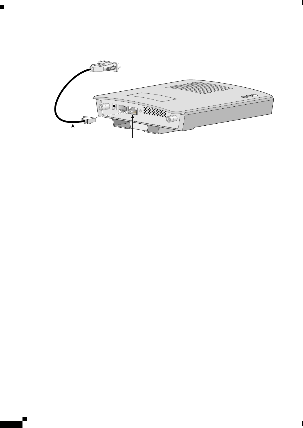
Draft Copy - CISCO CONFIDENTIAL
3-10
Cisco Aironet 1200 Series Access Point Hardware Installation Guide
OL-2155-02
Chapter 3 Basic Configuration
Entering Basic Settings
Figure 3-4 shows the location of the access point’s console port.
Figure 3-4 Connecting the Serial Cable
Step 2 Open your terminal emulator program.
Step 3 Enter these settings for the connection into your terminal emulator program:
•Bits per second (baud rate): 9600
•Data bits: 8
•Parity: No parity
•Stop bits: 1
•Flow control: Xon/Xoff or None
Step 4 Press = to display the home page of the access point.
If the access point is new and its factory configuration has not been changed, the Express Setup page
appears. Go to Step 5.
If the access point has been configured, the Summary Status page appears. Perform the following
additional steps:
a. Type s and the Setup screen appears.
b. Type ex and the Express Setup screen appears.
c. Go to Step 5.
Step 5 Type na to select System Name. Enter a system name for the access point and press Enter. A descriptive
system name makes it easy to identify the access point on your network.
Step 6 Type t and then press Enter to select Terminal Type. To specify the type of console interface, perform
one of the following steps:
a. Type t and then press Enter to select teletype display on the console interface.
b. Type a and then press Enter to select ANSI display on the console interface.
Step 7 Type pr and then press Enter to select Config Server Protocol. To select the type of protocol, perform
one of the following steps:
•Type n to select none and press Enter after you make your selection.
•Type b to select BOOTP and press Enter after you make your selection.
•Type d to select DHCP and press Enter after you make your selection.
RJ-45 serial
connector
DB-9 to RJ-45
serial cable
74005

Draft Copy - CISCO CONFIDENTIAL
3-11
Cisco Aironet 1200 Series Access Point Hardware Installation Guide
OL-2155-02
Chapter 3 Basic Configuration
Entering Basic Settings
Step 8 Type ad and then press Enter to select IP Address. Enter an IP address for the access point.
•If DHCP or BOOTP is not enabled, your entry is the access point’s static IP address.
•If DHCP or BOOTP is enabled, your entry provides the IP address only when the DHCP or BOOTP
server does not respond.
Step 9 Type su and then press Enter to select IP Subnet Mask. Enter an IP subnet mask to identify the
subnetwork so the access point’s IP address can be recognized on the LAN.
•If DHCP or BOOTP is not enabled, your entry is the static subnet mask.
•If DHCP or BOOTP is enabled, your entry provides the subnet mask only when the DHCP or
BOOTP server does not respond.
Step 10 Type g and then press Enter to select Default Gateway. Enter the IP address of your default gateway.
The entry 255.255.255.255 indicates no gateway.
•If DHCP or BOOTP is not enabled, your entery is the static default gateway address.
•If DHCP or BOOTP is enabled, your entry provides the default gateway IP address only when a
DHCP or BOOTP server does not respond.
Step 11 For the AP Radio: Internal (2.4-GHz) settings, perform the following steps:
Note The radio parameters can be different for the 2.4-GHz and 5-GHz wireless LANs.
a. Type ra and then press Enter to select Radio Service Set ID (SSID). Enter an SSID for the access
point. The SSID is a unique identifier that client devices use to associate with the access point. The
SSID can be any alphanumeric entry from 2 to 32 characters long.
b. Type ro and then press Enter to select Role in Radio Network. The network roles include the
following options:
–
Root Access Point—Type ro and then press Enter to select this setting. A wireless LAN
transceiver that connects an Ethernet network with wireless client stations. Use this setting if
the access point will be connected to the wired LAN.
–
Repeater Access Point—Type re and then press Enter to select this setting. An access point that
transfers data between a client and another access point. Use this setting for access points not
connected to the wired LAN.
–
Site Survey Client—Type s and then press Enter to select this setting. A station with a wireless
connection to an access point. Use this setting for diagnostics, such as when you need to test the
access point by having it communicate with another access point.
c. Type op and then press Enter to select Optimize Radio Network For. These options assign either
preconfigured settings or customized settings for the access point radio:
–
Throughput—Type t and then press Enter to select this setting. Maximizes the data volume
handled by the access point but might reduce the access point’s range.
–
Range—Type r and then press Enter to select this setting. Maximizes the access point’s range
but might reduce throughput.
–
Custom—Type c and then press Enter to select this setting. The access point uses the settings
you enter on the AP Radio Hardware page. For additional information on the AP Radio
Hardware page, refer to the Cisco Aironet 1200 Series Access Point Software Configuration
Guide.

Draft Copy - CISCO CONFIDENTIAL
3-12
Cisco Aironet 1200 Series Access Point Hardware Installation Guide
OL-2155-02
Chapter 3 Basic Configuration
Entering Basic Settings
d. Use the Ensure Compatibility With setting to automatically configure the access point to be
compatible with other devices on your wireless LAN:
–
2-Mbps clients—Type 2 and then press Enter to select this setting. Select this setting if your
network contains Cisco Aironet devices that operate at 2 Mbps.
–
non-Aironet 802.11—Type no and then press Enter to select this setting. Select this setting if
there are non-Cisco Aironet devices on your wireless LAN.
Step 12 For the AP Radio: Module (5-GHz) settings, perform the following steps:
Note The radio parameters can be different for the 2.4-GHz and 5-GHz wireless LANs.
a. Type ra and then press Enter to select Radio Service Set ID (SSID). Enter an SSID for the access
point. The SSID is a unique identifier that client devices use to associate with the access point. The
SSID can be any alphanumeric entry from 2 to 32 characters long.
b. Type ro and then press Enter to select Role in Radio Network. The network roles include the
following options:
–
Root Access Point—Type ro and then press Enter to select this setting. A wireless LAN
transceiver that connects an Ethernet network with wireless client stations. Use this setting if
the access point will be connected to the wired LAN.
–
Repeater Access Point—Type re and then press Enter to select this setting. An access point that
transfers data between a client and another access point. Use this setting for access points not
connected to the wired LAN.
–
Site Survey Client—Type s and then press Enter to select this setting. A station with a wireless
connection to an access point. Use this setting for diagnostics, such as when you need to test the
access point by having it communicate with another access point.
c. Type op and then press Enter to select Optimize Radio Network For. These options assign either
preconfigured settings or customized settings for the access point radio:
–
Throughput—Type t and then press Enter to select this setting. Maximizes the data volume
handled by the access point but might reduce the access point’s range.
–
Range—Type r and then press Enter to select this setting. Maximizes the access point’s range
but might reduce throughput.
–
Custom—Type c and then press Enter to select this setting. The access point uses the settings
you enter on the AP Radio Hardware page. For additional information on the AP Radio
Hardware page, refer to the Cisco Aironet 1200 Series Access Point Software Configuration
Guide.
Step 13 Type sn and then press Enter to select SNMP Admin. Community. Enter an SNMP community name.
This name automatically appears in the list of users authorized to view and make changes to the access
point’s management system.
You can define other SNMP communities with User Management. For additional information on SNMP,
refer to the Cisco Aironet 1200 Series Access Point Software Configuration Guide.
Step 14 Type ap and press Enter to apply your basic settings. Your basic configuration is complete, you can
close your terminal emulator.
For additional information on security options, refer to the Cisco Aironet 1200 Series Access Point
Software Configuration Guide.

Draft Copy - CISCO CONFIDENTIAL
3-13
Cisco Aironet 1200 Series Access Point Hardware Installation Guide
OL-2155-02
Chapter 3 Basic Configuration
Default Basic Settings
Default Basic Settings
Table 3-1 lists the default settings on the access point’s Express Setup screen.
Table 3-1 Default Settings on the Express Setup Screen
Parameter Default Value
System Name AP1200-xxxxxx (the last six characters of the
unit’s MAC address)
Terminal Type (on serial interface only) teletype
Config Server Protocol DHCP
IP address 10.0.0.1
IP Subnet Mask 255.255.255.0
Default Gateway 255.255.255.255
AP Radio: Internal (2.4-GHz radio)
SSID tsunami
Role in Radio Network Root Access Point
Optimize Radio Network For Throughput
AP Radio: Module (5-GHz radio)
SSID tsunami
Role in Radio Network Root Access Point
Optimize Radio Network For Throughput
Ensure Compatibility With (none selected)
SNMP Admin. Community (blank)

Draft Copy - CISCO CONFIDENTIAL
3-14
Cisco Aironet 1200 Series Access Point Hardware Installation Guide
OL-2155-02
Chapter 3 Basic Configuration
Default Basic Settings

CHAPTER
4-1
Cisco Aironet 1200 Series Access Point Hardware Installation Guide
OL-2155-02
4
Mounting Instructions
This chapter provides instructions for mounting the access point to suspended ceilings, vertical surfaces,
or horizontal surfaces using the access point mounting bracket.
The following sections are included in this chapter:
•Overview, page 4-2
•Mounting on a Horizontal or Vertical Surface, page 4-3
•Mounting on a Suspended Ceiling, page 4-4
•Attaching the Access Point to the Mounting Bracket, page 4-5
•Securing the Access Point to the Mounting Bracket, page 4-5
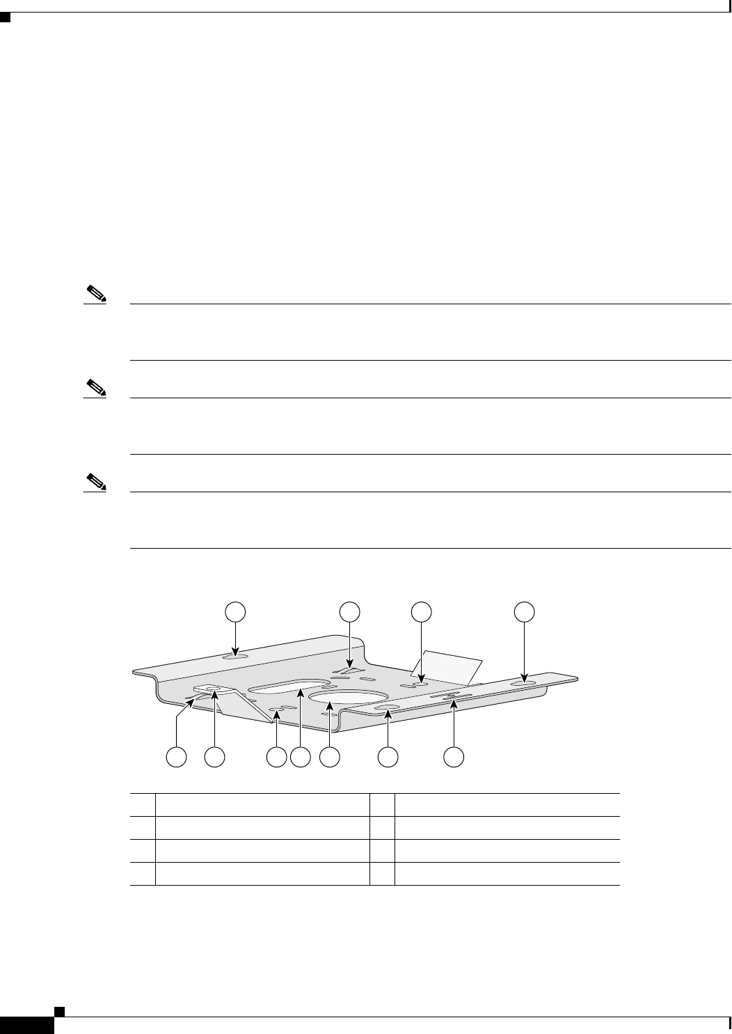
Draft Copy - CISCO CONFIDENTIAL
4-2
Cisco Aironet 1200 Series Access Point Hardware Installation Guide
OL-2155-02
Chapter 4 Mounting Instructions
Overview
Overview
You can mount the access point on any of the following surfaces:
•Horizontal or vertical flat surfaces, such as walls or ceilings
•Suspended ceilings
The access point ships with a detachable mounting bracket and the necessary mounting hardware.
Because it is detachable, you can use the mounting bracket as a template to mark the positions of the
mounting holes for your installation. You then install the mounting bracket and attach the access point
when you are ready. Refer to Figure 4-1 to locate the various mounting holes for the method you intend
to use.
Note The Cisco Aironet 1200 Series Access Point provides adequate fire resistance and low-smoke-producing
characteristics suitable for operation in a building's environmental air space in accordance with Section
300-22(C) of the National Electrical Code (NEC), such as above suspended ceilings.
Note If you plan to mount the access point with the 5-GHz radio in environmental air space, Cisco
recommends that you mount the access point horizontally with its antennas pointing down. Doing so
results in the access point complying with regulatory requirements for environmental air space.
Note When mounting the access point in a building’s environmental air space, you must use Ethernet cable
suitable for operation in environmental air space in accordance with Section 300-22(C) of the National
Electrical Code (NEC).
Figure 4-1 Mounting Bracket
1
546738
2 3 4
65863
2
1Access point mount 5Locking detent
2Cable tie points 6Wall cable access
3Ceiling mount holes 7Suspended ceiling cable access
4Access point mounts 8Security hasp

Draft Copy - CISCO CONFIDENTIAL
4-3
Cisco Aironet 1200 Series Access Point Hardware Installation Guide
OL-2155-02
Chapter 4 Mounting Instructions
Mounting on a Horizontal or Vertical Surface
A mounting hardware kit is provided that contains the hardware and fasteners necessary to mount the
access point. Refer to the Table 4-1 to identify the materials you need to mount your access point, then
go to the section containing the specific mounting procedure.
Mounting on a Horizontal or Vertical Surface
Follow these steps to mount the access point on a horizontal or vertical surface.
Step 1 Use the mounting bracket as a template to mark the locations of the four mounting holes.
Step 2 Drill one of the following sized holes at the locations you marked:
•3/16 in. (4.7 mm) if you are using wall anchors
•1/8 in. (6.3 mm) if you are not using wall anchors
Step 3 Install the anchors into the wall if you are using them. Otherwise, go to Step 4.
Step 4 Secure the mounting bracket to the surface using the #8 fasteners.
Note On a vertical surface, mount the bracket with its security hasp facing down.
Step 5 Attach the access point to the mounting bracket.
Note You can make your installation more secure by mounting it to a stud or major structural member
and using the appropriate fasteners.
Table 4-1 Material Needed to Mount Access Point
Mounting Method Materials Required In Kit
Horizontal or vertical surface Four #8 x 1 in. (25.4 mm) screws
Four wall anchors
3/16 in. (4.7 mm) or 3/32 in. (2.3 mm) drill bit
Drill
Standard screwdriver
Yes
Yes
No
No
No
Suspended ceiling Two caddy fasteners with studs
Two plastic spacers
Two 1/4–20 Keps nuts with built-in washers
Standard screwdriver
Appropriate wrench or pliers
Yes
Yes
Yes
No
No
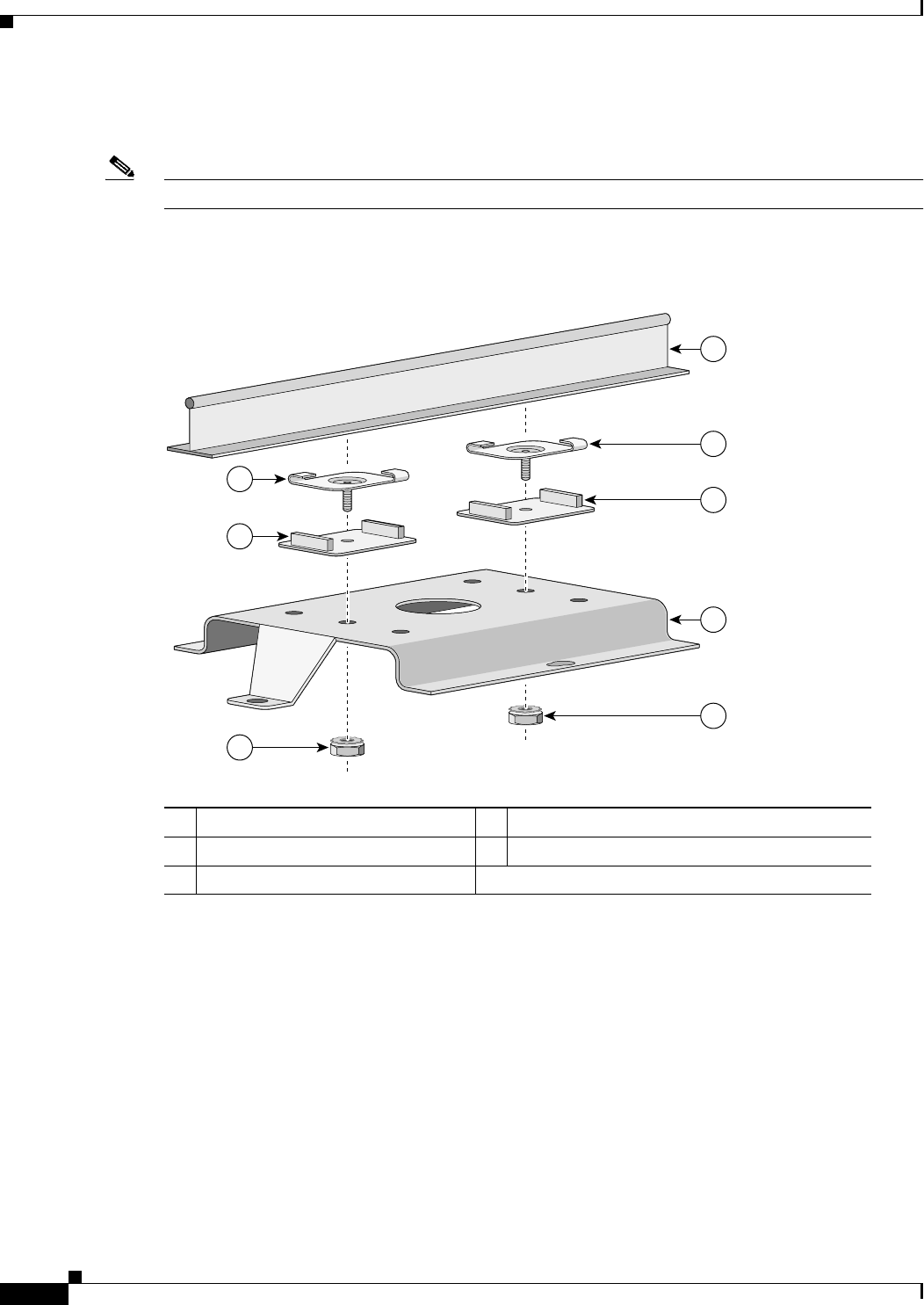
Draft Copy - CISCO CONFIDENTIAL
4-4
Cisco Aironet 1200 Series Access Point Hardware Installation Guide
OL-2155-02
Chapter 4 Mounting Instructions
Mounting on a Suspended Ceiling
Mounting on a Suspended Ceiling
Note To comply with NEC code, a #10-24 grounding lug is provided on the mounting bracket.
You should review Figure 4-2 before beginning the mounting process.
Figure 4-2 Mounting Bracket Parts
1
2
2
3
5
3
4
5
74121
1Suspended ceiling T-rail 4Mounting bracket
2Caddy fastener 5Keps nut (contains an attached lock washer)
3Plastic spacer

Draft Copy - CISCO CONFIDENTIAL
4-5
Cisco Aironet 1200 Series Access Point Hardware Installation Guide
OL-2155-02
Chapter 4 Mounting Instructions
Attaching the Access Point to the Mounting Bracket
Follow these steps to mount your access point on a suspended ceiling.
Step 1 Determine the location where you want to mount the access point.
Step 2 Attach two caddy fasteners to the suspended ceiling T-rail.
Step 3 Use the mounting bracket to adjust the distance between the caddy fasteners so that they align with the
holes in the mounting bracket.
Step 4 Use a standard screwdriver to tighten the caddy fastener studs in place on the suspended ceiling T-rail.
Do not overtighten.
Step 5 Install a plastic spacer on each caddy fastener stud. The spacer’s legs should contact the suspended
ceiling T-rail.
Step 6 Attach the mounting bracket to the caddy fastener studs and start a Keps nut on each stud.
Step 7 Use a wrench or pliers to tighten the Keps nuts. Do not overtighten.
Step 8 Attach the access point to the mounting bracket.
Attaching the Access Point to the Mounting Bracket
Follow these steps to attach the access point to the mounting bracket.
Step 1 Line up the three mounting pins on the access point with the large ends of the keyhole-shaped holes on
the mounting bracket.
Step 2 Insert the access point into the keyhole shaped holes and maintain a slight pressure to hold it in place.
Step 3 Slide the access point’s mounting pins into the small ends of the keyhole-shaped holes on the mounting
bracket and push the connector end of the access point. You will hear a click when the locking detent
contacts the access point and locks it into place.
Step 4 Attach and adjust the antenna(s) or antenna cables.
Step 5 Connect the Ethernet cable to the access point’s Ethernet port.
Step 6 Insert the 1200 series power module cable connector into the access point’s 48VDC power port (if you
are using a local power source).
Securing the Access Point to the Mounting Bracket
The security hasp on the mounting bracket enables you to lock the access point to the bracket to make it
more secure. When the access point is properly installed on the mounting bracket, the holes in the
security hasps line up so you can install a padlock.
Known compatible padlocks are Master Lock models 120T or 121T.

Draft Copy - CISCO CONFIDENTIAL
4-6
Cisco Aironet 1200 Series Access Point Hardware Installation Guide
OL-2155-02
Chapter 4 Mounting Instructions
Securing the Access Point to the Mounting Bracket

CHAPTER
5-1
Cisco Aironet 1200 Series Access Point Hardware Installation Guide
OL-2155-02
5
2.4-GHz Radio Upgrade
This section contains the following topics:
•Overview, page 5-2
•Opening the Access Cover, page 5-3
•Removing a Blank Spacer Card, page 5-4
•Removing a 2.4-GHz Radio, page 5-5
•Installing a 2.4-GHz Radio, page 5-7

Draft Copy - CISCO CONFIDENTIAL
5-2
Cisco Aironet 1200 Series Access Point Hardware Installation Guide
OL-2155-02
Chapter 5 2.4-GHz Radio Upgrade
Overview
Overview
This section provides instructions for upgrading the access point 2.4-GHz radio. The following
operations summarize the upgrade procedure:
•Remove all cables and power connections from the access point.
•Follow standard Electro Static Discharge procedures.
•Place the access point on an ESD-protected work surface.
•Open the access point’s 2.4-GHz radio access cover.
•For an access point without the 2.4-GHz radio feature, remove the blank spacer card.
•For an access point with the 2.4-GHz radio feature, remove the existing 2.4-GHz card.
•Install the new 2.4-GHz radio card.
•Close the access point 2.4-GHz radio access cover.
Caution Electrostatic discharge (ESD) can damage the Cisco Aironet radio and the internal components of the
access point. It is recommended that the 2.4-GHz radio upgrade procedures be performed by an
ESD-trained service technician at an ESD-protected workstation.
Unpacking the Radio
Each 2.4-GHz radio is shipped with the following items:
•Quick start guide
•A product registration card
•A T-10 tamper-resistant Torx L-wrench
•A 2.4 GHz radio product compliance label
If anything is missing or damaged, contact your Cisco representative for support.
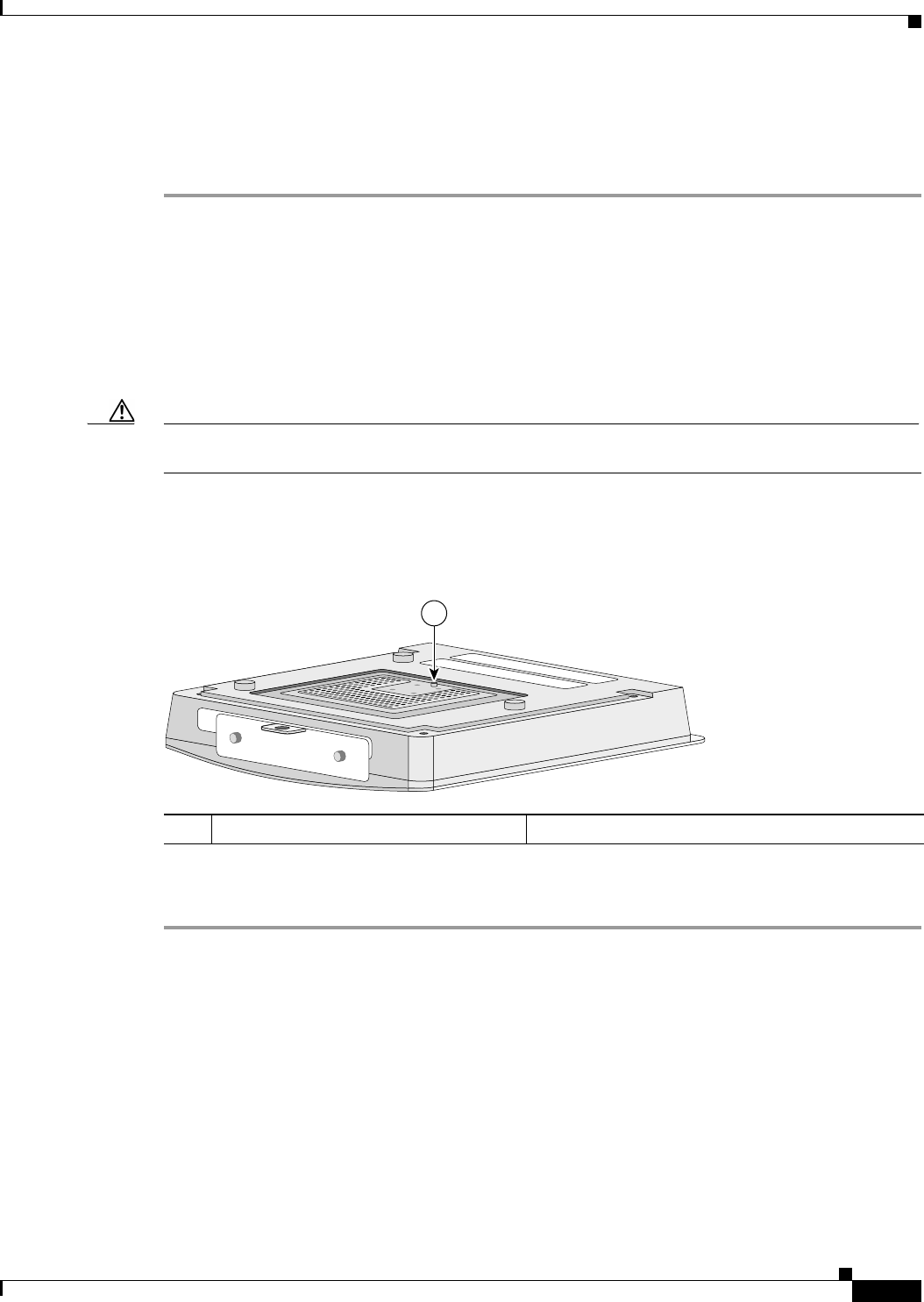
Draft Copy - CISCO CONFIDENTIAL
5-3
Cisco Aironet 1200 Series Access Point Hardware Installation Guide
OL-2155-02
Chapter 5 2.4-GHz Radio Upgrade
Opening the Access Cover
Opening the Access Cover
To open the 2.4-GHz radio access cover, follow the steps below:
Step 1 Remove all cables and power connections from the access point.
Step 2 Remove all static generating items from the work area, such as plastic material, styrofoam cups, and
other similar items.
Step 3 Place the access point and the new 2.4-GHz radio (in its antistatic bag) on an antistatic work surface.
Step 4 Discharge any static buildup on your body by touching a grounded surface (antistatic work surface)
before proceeding.
Step 5 Position the access point so that the bottom cover is facing up.
Caution The internal access point components and the 2.4-GHz radio can be damaged by ESD from improper
handling.
Step 6 Remove the bottom access cover (see Figure 5-1) using the T-10 tamper-resistant Torx L-wrench
provided with your Cisco radio card.
Figure 5-1 Location of 2.4-GHz Radio Access Cover Screw
If your access point was not configured with a 2.4-GHz radio, go to the “Removing a Blank Spacer Card”
section. If you are replacing an existing 2.4-GHz radio, go to the “Removing a 2.4-GHz Radio” section.
1Access Cover Screw
1
74458
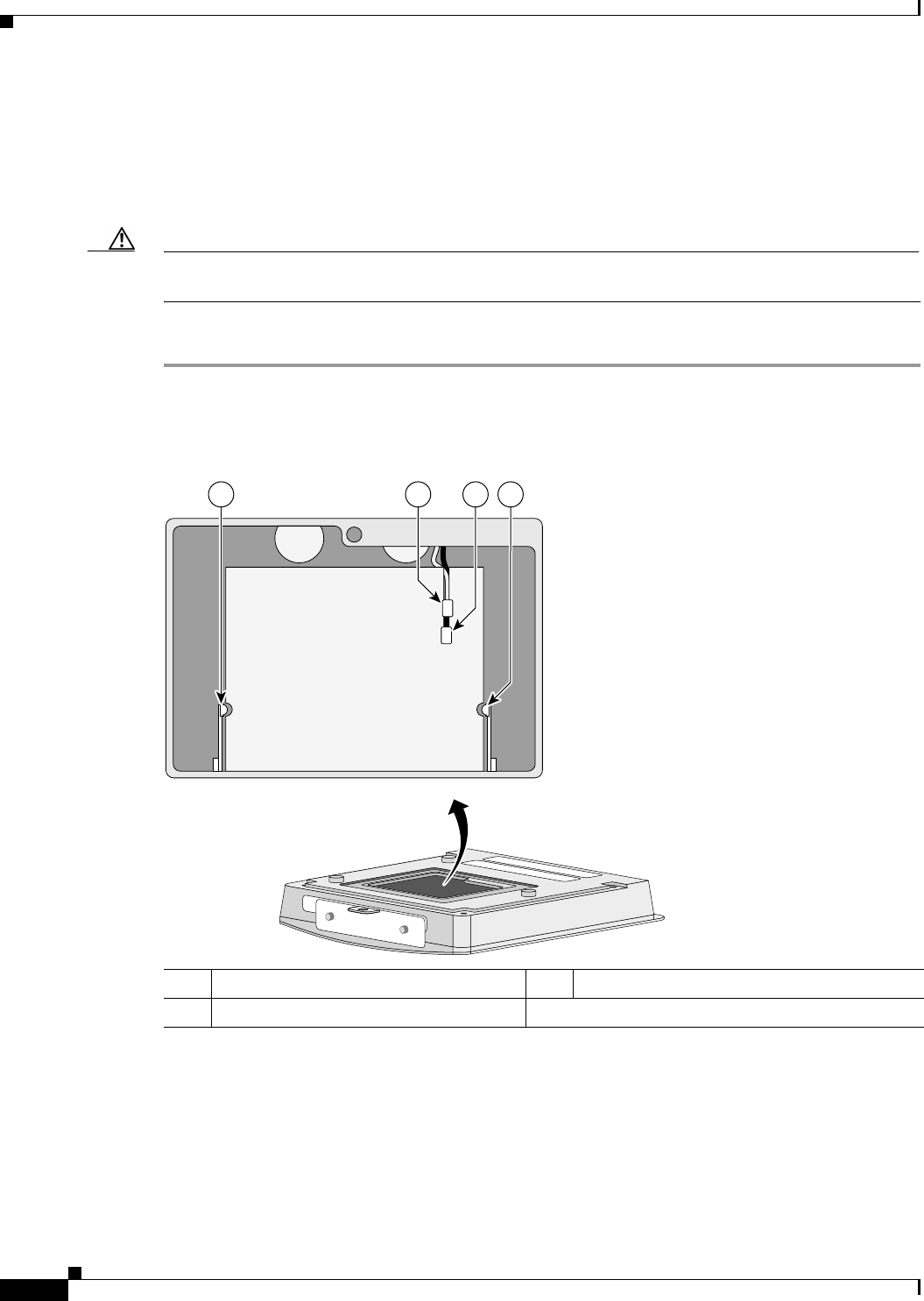
Draft Copy - CISCO CONFIDENTIAL
5-4
Cisco Aironet 1200 Series Access Point Hardware Installation Guide
OL-2155-02
Chapter 5 2.4-GHz Radio Upgrade
Removing a Blank Spacer Card
Removing a Blank Spacer Card
When your access point is not factory-configured with a 2.4-GHz radio, it contains a blank spacer card
in the internal mini-PCI connector. You must remove the blank spacer card prior to installing a new
2.4-GHz radio card.
Caution Handle all components carefully and observe all ESD precautions. The internal access point components
and the 2.4-GHz radio can be damaged by ESD from improper handling.
To remove the blank spacer card from the mini-PCI connector, following the steps below:
Step 1 Push the card-retaining clips (on each side of card) away from the card (see Figure 5-2). When released,
the board springs up.
Figure 5-2 Location of Retaining Clips on Blank Spacer Card
Step 2 Carefully bend the card near the slots in opposite directions to provide enough clearance to remove the
antenna wires.
1Card-retaining clips 2Antenna connector (white wire)
3Antenna connector (black wire)
74248
1 3 12

Draft Copy - CISCO CONFIDENTIAL
5-5
Cisco Aironet 1200 Series Access Point Hardware Installation Guide
OL-2155-02
Chapter 5 2.4-GHz Radio Upgrade
Removing a 2.4-GHz Radio
Step 3 Remove the antenna wires from the blank spacer card.
Caution To avoid damaging the antenna wire assemblies, handle them by their connectors.
Step 4 Remove the blank spacer card from the mini-PCI connector.
For instructions on installing the radio card, go to the “Installing a 2.4-GHz Radio” section.
Removing a 2.4-GHz Radio
To remove a 2.4-GHz radio card from your access point, follow the steps below:
Caution The internal access point components and the 2.4-GHz radio can be damaged by ESD from improper
handling.
Step 1 Use your fingers to carefully remove the antenna wire connectors from the 2.4-GHz radio card.
Caution The antenna connectors can be damaged by using a pair of long-nose pliers during the removal
process.
Caution To avoid damaging the antenna wire assemblies, handle them by their connectors.
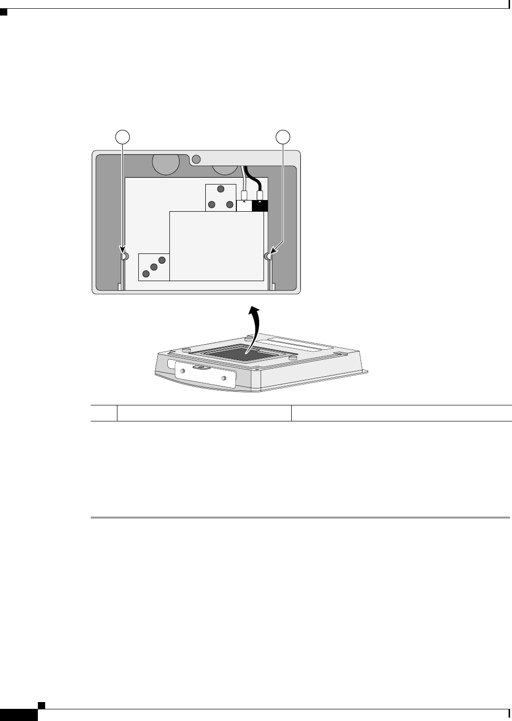
Draft Copy - CISCO CONFIDENTIAL
5-6
Cisco Aironet 1200 Series Access Point Hardware Installation Guide
OL-2155-02
Chapter 5 2.4-GHz Radio Upgrade
Removing a 2.4-GHz Radio
Step 2 Remove the 2.4-GHz radio card from the mini-PCI connector by performing the following operations:
a. Push the card-retaining clips (on each side of card) away from the card (see Figure 5-3). When
released, the radio card springs up (see Figure 5-4).
Figure 5-3 Location of Retaining Clips on 2.4-GHz Radio Card
b. Grasp the radio card only on the edges, being careful not to touch components on the board or the
gold connector pins.
c. Remove the 2.4-GHz card from the mini-PCI connector.
Step 3 Place the removed 2.4GHz radio card into an anti-static bag.
For instructions on installing a new radio card, go to the “Installing a 2.4-GHz Radio” section.
1Card-retaining clips
MAIN AUX
74253
1 1
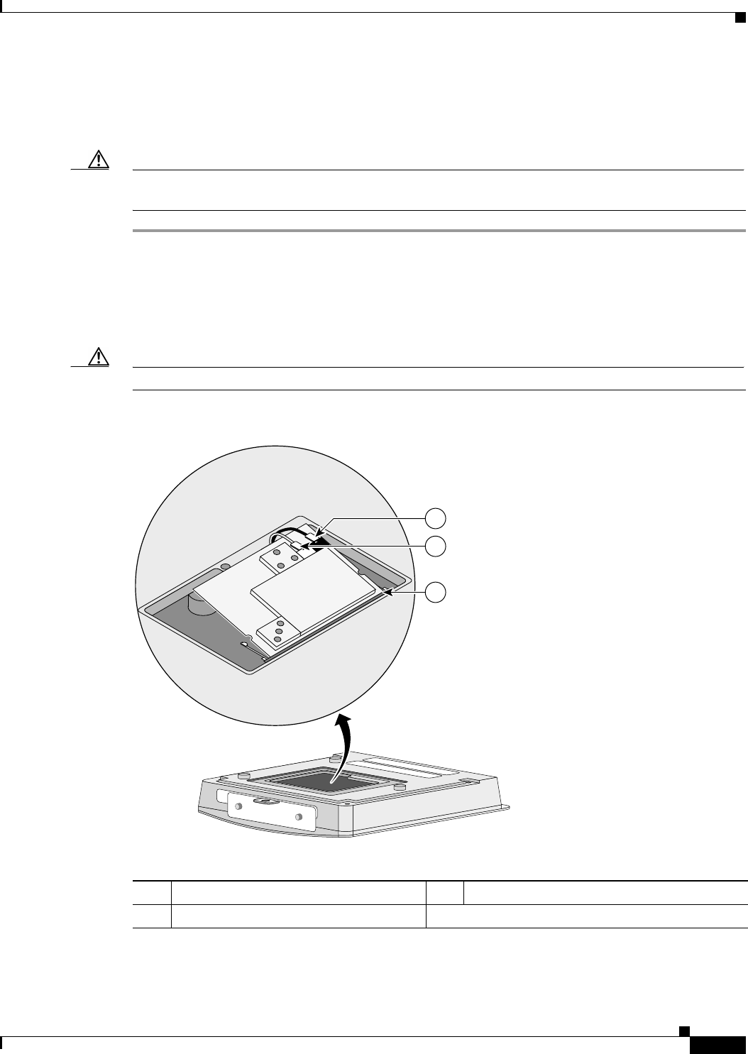
Draft Copy - CISCO CONFIDENTIAL
5-7
Cisco Aironet 1200 Series Access Point Hardware Installation Guide
OL-2155-02
Chapter 5 2.4-GHz Radio Upgrade
Installing a 2.4-GHz Radio
Installing a 2.4-GHz Radio
To install a new 2.4-GHz radio card into the access point, follow the steps below.
Caution The internal access point components and the 2.4-GHz radio can be damaged by ESD from improper
handling.
Step 1 Carefully remove the Cisco Aironet 2.4-GHz radio card from its anti-static bag.
Step 2 Grasp the radio card only on the edges, being careful not to touch components on the board or the gold
connector pins.
Step 3 Connect the black antenna wire connector to the radio card antenna connector marked by the black label
(see Figure 5-4).
Caution To avoid damaging the antenna wire assemblies, handle them by their connectors.
Figure 5-4 Antenna Connector Labels and Mini-PCI Connector
Step 4 Connect the white antenna wire connector to the radio card antenna connector marked by the white label
(see Figure 5-4).
MAIN AUX
74251
3
2
1
1Antenna connector (black wire) 2Antenna connector (white wire)
3Mini-PCI connector
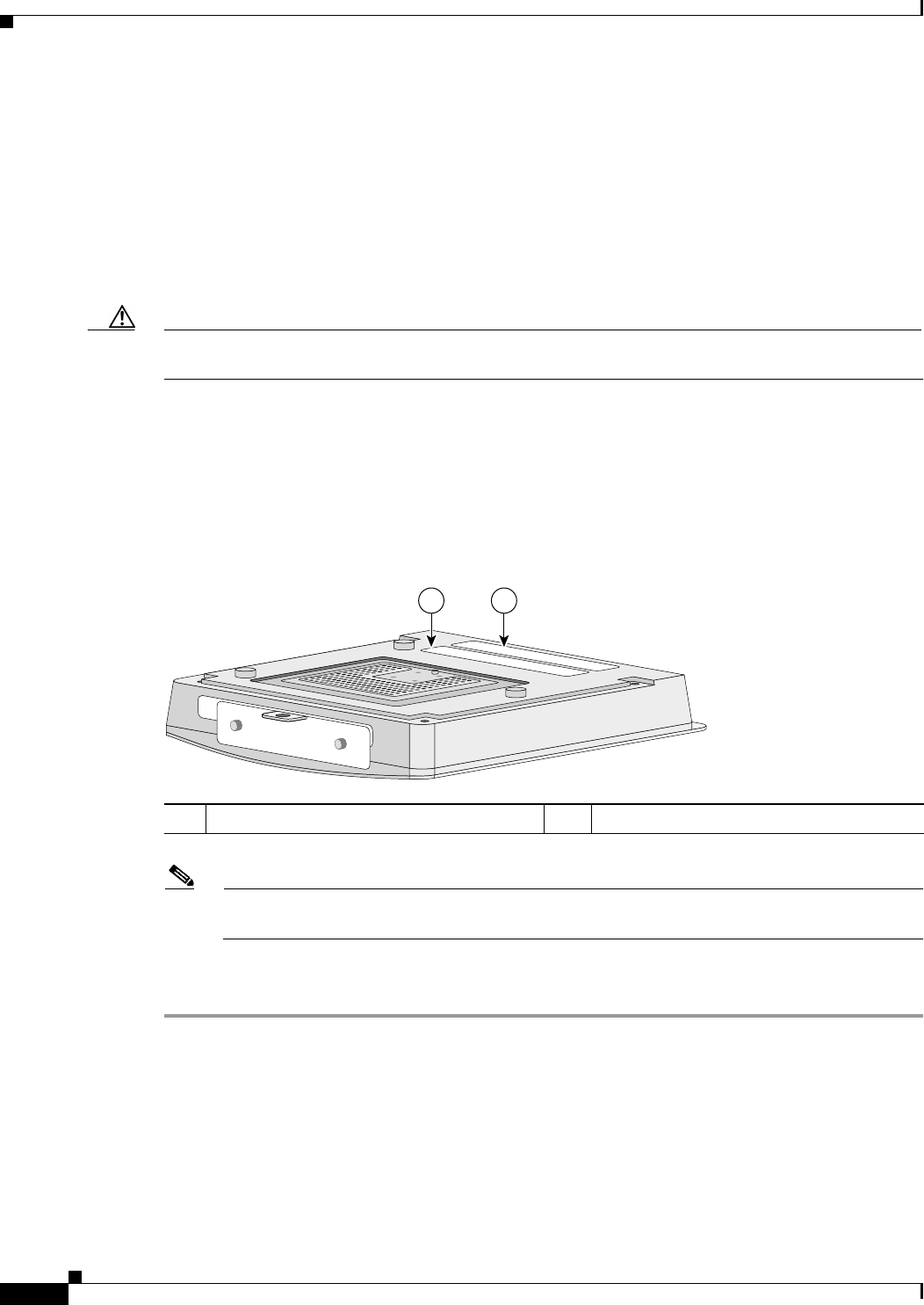
Draft Copy - CISCO CONFIDENTIAL
5-8
Cisco Aironet 1200 Series Access Point Hardware Installation Guide
OL-2155-02
Chapter 5 2.4-GHz Radio Upgrade
Installing a 2.4-GHz Radio
Step 5 Insert the radio card into the access point’s mini-PCI connector by following the steps below:
a. Tilt the radio card at approximately 20o to 30o so that its gold pins are aligned with the mini-PCI
connector (see Figure 5-4).
b. Push the card into the mini-PCI connector unil it clicks into place.
Step 6 Carefully push the card down (towards the access point’s motherboard) until the card-retaining clips lock
into the notches on the side of the radio card (you will hear a click).
Step 7 Carefully position the antenna wires so that the metal connectors do not touch each other.
Caution Damage to the radio could occur if the antenna connectors are touching when power is applied. If they
are touching, carefully rotate them in opposite directions until they are separated.
Step 8 Reinstall the 2.4-GHz radio access cover and use the T-10 tamper-resistant Torx L-wrench to tighten the
cover’s retaining screw.
Step 9 Remove the backing paper from the 2.4-GHz radio product compliance label.
Step 10 Carefully attach the label in the space provided below the access point’s product compliance label as
shown in Figure 5-5.
Figure 5-5 Location of Product Compliance Labels
Note If your access point contains a 5-GHz radio module, there will also be a 5-GHz radio product
compliance label on the back of the unit.
The radio card installation is now complete. To configure the 2.4-GHz radio card with your wireless
network settings refer to the Cisco Aironet 1200 Series Access Point Software Configuration Guide.
12.4-GHz radio product compliance label 2Access point product compliance label
1 2
74246

CHAPTER
6-1
Cisco Aironet 1200 Series Access Point Hardware Installation Guide
OL-2155-02
6
5-GHz Radio Module Upgrade
This chapter provides upgrade instructions for the 5-GHz radio module and includes the following
sections:
•Overview, page 6-2
•Removing the 5-GHz Radio Access Cover, page 6-2
•Removing a 5-GHz Radio Module, page 6-3
•Installing a 5-GHz Radio Module, page 6-5

Draft Copy - CISCO CONFIDENTIAL
6-2
Cisco Aironet 1200 Series Access Point Hardware Installation Guide
OL-2155-02
Chapter 6 5-GHz Radio Module Upgrade
Overview
Overview
This section provides instructions for upgrading the access point 5-GHz radio module. The following
operations summarize the upgrade procedure:
1. Remove all cables and power connections from the access point.
2. Place your access point on a flat surface.
3. For an access point without the 5-GHz radio feature, remove the 5-GHz radio access cover.
4. For an access point with the 5-GHz radio feature, remove the existing 5-GHz radio module.
5. Install the new 5-GHz radio module.
Unpacking the Radio Module
Each 5-GHz radio module is shipped with the following items:
•Quick start guide
•A product registration card
•A T-10 tamper-resistant Torx L-wrench
•A 5-GHz radio product compliance label
If anything is missing or damaged, contact your Cisco representative for support.
Removing the 5-GHz Radio Access Cover
To remove the 5-GHz radio access cover, follow the instructions below:
Step 1 Remove all cables and power connections from the access point.
Step 2 Place the access point on a flat surface so that the unit is upright with the front end facing you.
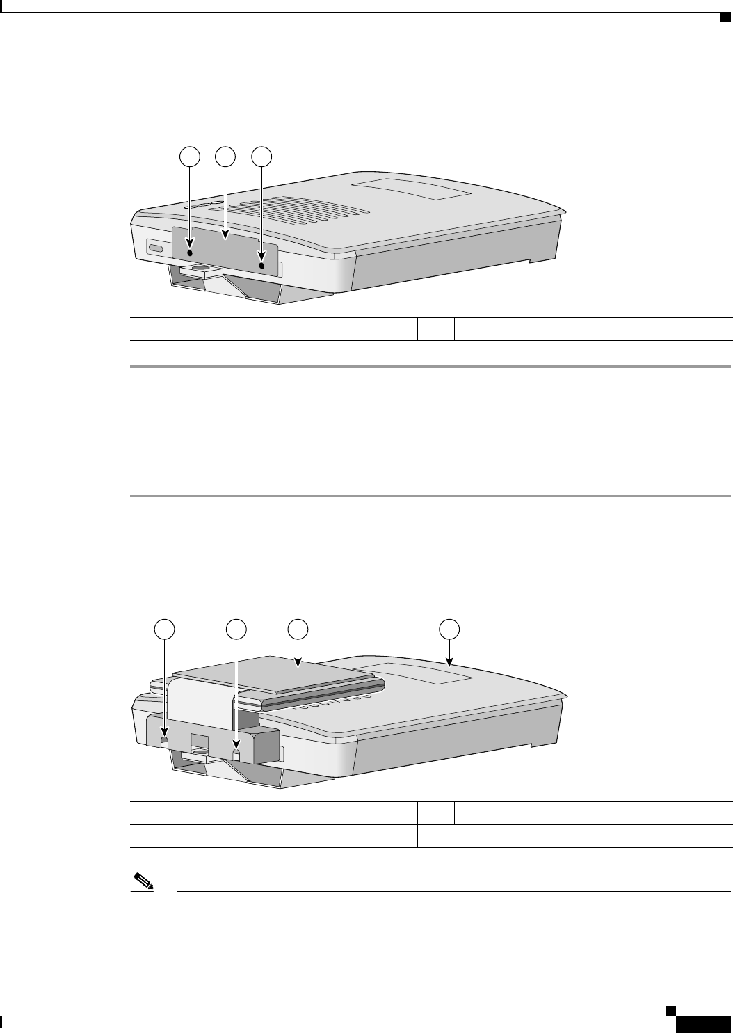
Draft Copy - CISCO CONFIDENTIAL
6-3
Cisco Aironet 1200 Series Access Point Hardware Installation Guide
OL-2155-02
Chapter 6 5-GHz Radio Module Upgrade
Removing a 5-GHz Radio Module
Step 3 Remove the 5-GHz access cover (see Figure 6-1) using the supplied Torx L-wrench.
Figure 6-1 5-GHz Radio Access Cover
Removing a 5-GHz Radio Module
To remove the 5-GHz radio module, follow the instructions below:
Step 1 Remove all cables and power connections from the access point.
Step 2 Place the access point on a flat surface so that the unit is upright with the front end facing you.
Step 3 Unscrew the two mounting screws using the supplied Torx L-wrench (Figure 6-2).
Figure 6-2 5-GHz Radio Module
Note Do not attempt to remove the mounting screws from the module; they are captured in the module
housing.
1Access Cover Screws 2 Access Cover
1 12
74632
1Mounting screws 25-GHz radio module antenna
3 Access point
74631
1 1 2 3
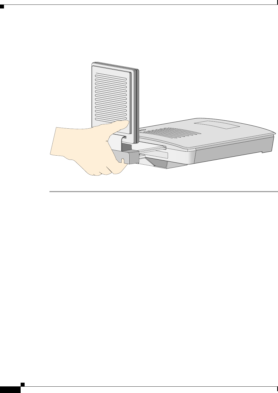
Draft Copy - CISCO CONFIDENTIAL
6-4
Cisco Aironet 1200 Series Access Point Hardware Installation Guide
OL-2155-02
Chapter 6 5-GHz Radio Module Upgrade
Removing a 5-GHz Radio Module
Step 4 Insert your fingers into the base of the 5-GHz radio module (closest to the access point) and pull straight
out from the access point (see Figure 6-3).
Figure 6-3 Removing the 5-GHz Radio Module
Step 5 Fold the antenna down (towards the attached radio card) and insert the module into a static protected bag.
74629
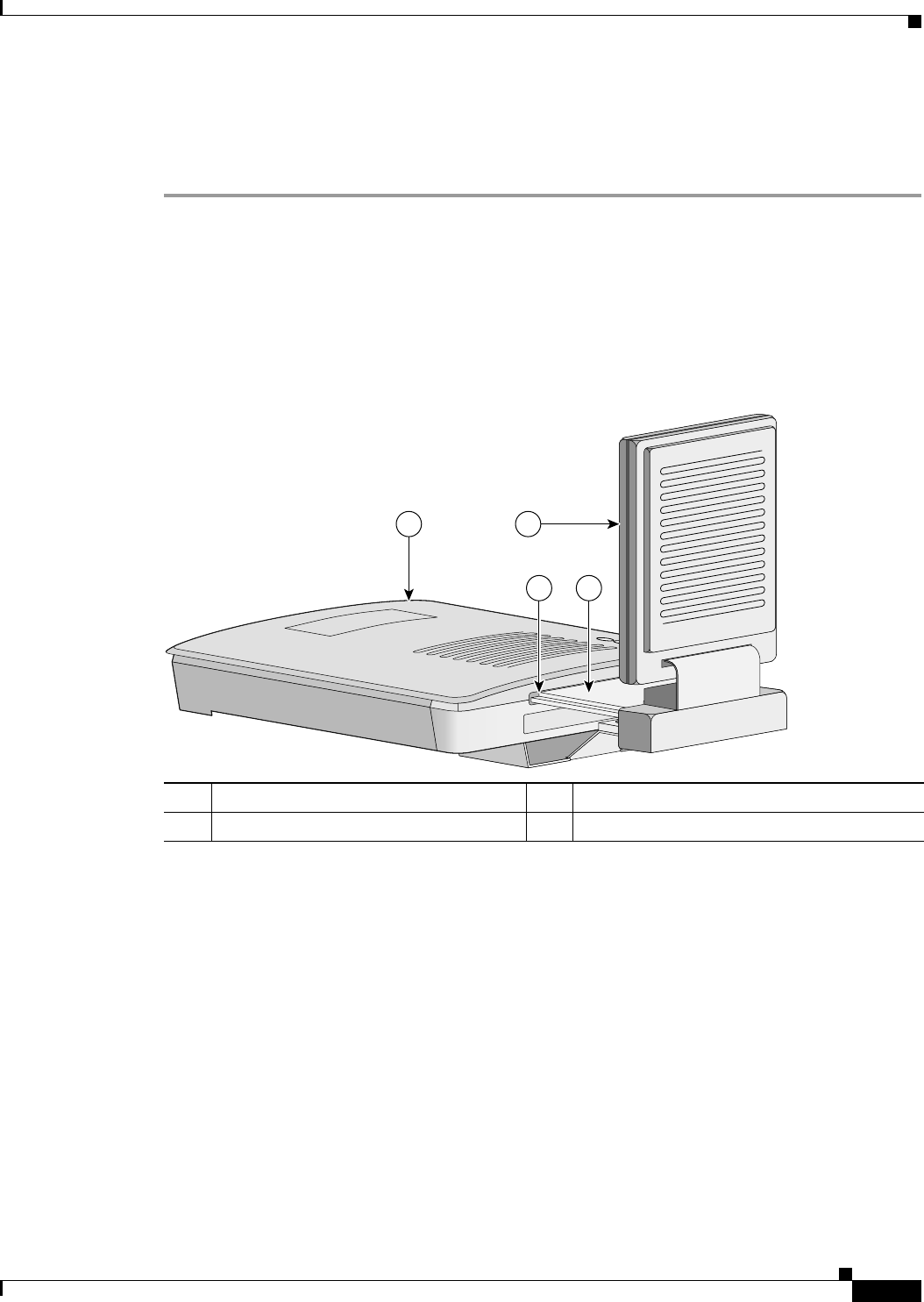
Draft Copy - CISCO CONFIDENTIAL
6-5
Cisco Aironet 1200 Series Access Point Hardware Installation Guide
OL-2155-02
Chapter 6 5-GHz Radio Module Upgrade
Installing a 5-GHz Radio Module
Installing a 5-GHz Radio Module
To install a new 5-GHz radio module into your access point, follow the steps below:
Step 1 Before you can install a new 5-GHz radio module, you must remove the access cover or an existing
5-GHz radio module (refer to “Removing the 5-GHz Radio Access Cover” or “Removing a 5-GHz Radio
Module”).
Step 2 Place the access point on a flat surface so that the unit is upright with the front end facing you.
Step 3 Grasp the new 5-GHz radio module by it’s base (with the antenna pointing up) and insert the card into
the access point’s card-bus slot (see Figure 6-4).
Figure 6-4 Installing a 5-GHz Radio Module
Step 4 Push the 5-GHz radio module into the slot until you hear a slight click.
1Access point 25-GHz radio module antenna
3Access point card-bus slot 45-GHz radio card
74604
21
3 4
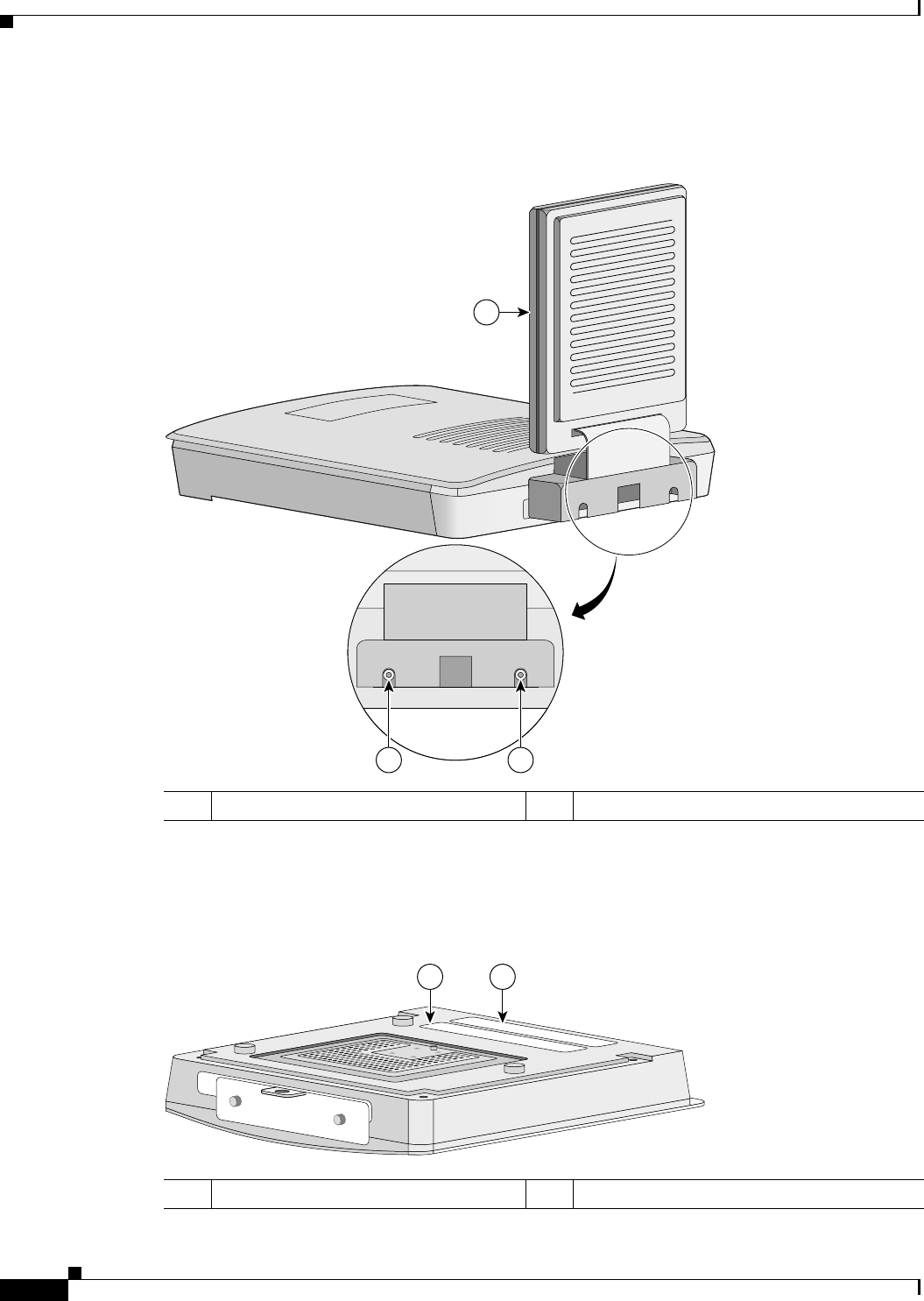
Draft Copy - CISCO CONFIDENTIAL
6-6
Cisco Aironet 1200 Series Access Point Hardware Installation Guide
OL-2155-02
Chapter 6 5-GHz Radio Module Upgrade
Installing a 5-GHz Radio Module
Step 5 Tighten the 5-GHz radio module mounting screws (see Figure 6-5) using the supplied Torx L-wrench.
Figure 6-5 Location of Mounting Screws
Step 6 Remove the backing paper from the 5-GHz radio product compliance label.
Step 7 Carefully attach the label in the space provided below the product compliance label (see Figure 6-6).
Figure 6-6 5-GHz Radio Product Compliance Label
15-GHz radio module antenna 2Mounting screws
2 2
1
74630
15-GHz radio product compliance label 2Access point product compliance label
1 2
74246

Draft Copy - CISCO CONFIDENTIAL
6-7
Cisco Aironet 1200 Series Access Point Hardware Installation Guide
OL-2155-02
Chapter 6 5-GHz Radio Module Upgrade
Installing a 5-GHz Radio Module
Note If your access point contains an internal 2.4-GHz radio, there will also be a 2.4-GHz radio
product compliance label on the back of the unit.
The 5-GHz radio module installation is now complete. To configure the 5-GHz radio with your wireless
network settings refer to Chapter 3, “Basic Configuration,” and to the Cisco Aironet 1200 Series Access
Point Software Configuration Guide.

Draft Copy - CISCO CONFIDENTIAL
6-8
Cisco Aironet 1200 Series Access Point Hardware Installation Guide
OL-2155-02
Chapter 6 5-GHz Radio Module Upgrade
Installing a 5-GHz Radio Module

CHAPTER
7-1
Cisco Aironet 1200 Series Access Point Hardware Installation Guide
OL-2155-02
7
Troubleshooting
This chapter provides troubleshooting procedures for basic problems with the access point. For
additional diagnostic and troubleshooting information, refer to the Cisco Aironet 1200 Series Access
Point Software Configuration Guide. For the most up-to-date troubleshooting information, refer to the
Cisco TAC website at the following URL (select Top Issues and then select Wireless Technologies):
http://www.cisco.com/tac
Sections in this chapter include:
•Checking the Top Panel Indicators, page 7-2
•Checking Basic Settings, page 7-3
•Resetting to the Default Configuration, page 7-4
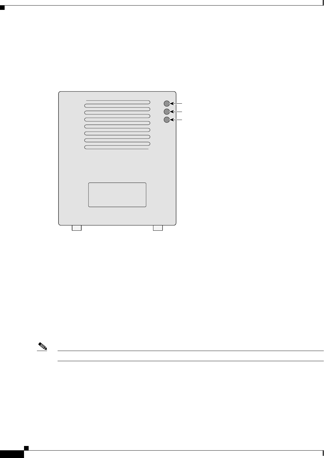
Draft Copy - CISCO CONFIDENTIAL
7-2
Cisco Aironet 1200 Series Access Point Hardware Installation Guide
OL-2155-02
Chapter 7 Troubleshooting
Checking the Top Panel Indicators
Checking the Top Panel Indicators
If your access point is not communicating, check the three indicators on the top panel. You can use them
to quickly assess the unit’s status. Figure 7-1 shows the indicators.
Figure 7-1 Indicators on the 1200 Series Access Point
The indicators signals have the following meanings:
•The Ethernet indicator signals traffic on the wired LAN, or Ethernet infrastructure. This indicator
blinks green when a packet is received or transmitted over the Ethernet infrastructure.
•The status indicator signals operational status. Blinking green indicates that the access point is
operating normally but is not associated with any wireless devices. Steady green indicates that the
access point is associated with a wireless client.
For repeater access points, blinking 50% on, 50% off indicates the repeater is not associated with
the root access point; blinking 7/8 on, 1/8 off indicates that the repeater is associated with the root
access point but no client devices are associated with the repeater; steady green indicates that the
repeater is associated with the root access point and client devices are associated with the repeater.
•The radio indicator blinks green to indicate radio traffic activity. The light is normally off, but it
blinks green whenever a packet is received or transmitted over the access point’s radio.
Note The Radio and Status indicators are used for both 2.4-GHz and 5-GHz radio operation.
Ethernet
Status
Radio
74046

Draft Copy - CISCO CONFIDENTIAL
7-3
Cisco Aironet 1200 Series Access Point Hardware Installation Guide
OL-2155-02
Chapter 7 Troubleshooting
Checking Basic Settings
Table 7-1 lists the meanings of the indicator signals.
Table 7-1 Top Panel Indicator Signals
Checking Basic Settings
Mismatched basic settings are the most common causes of lost connectivity with wireless clients. If the
access point does not communicate with client devices, check the following areas.
SSID
The wireless clients attempting to associate with the access point must use the same SSID as the access
point. The default SSID is tsunami for both the 2.4-GHz and 5-GHz radios.
Note The dual mode access point can support different SSIDs for the 2.4-GHz and 5-GHz radios.
Message
type
Ethernet
indicator
Status
indicator
Radio
indicator
Meaning
Association
status –Steady
green –At least one wireless client device is
associated with the unit.
–Blinking
green –No client devices are associated; check the
unit’s SSID and WEP settings.
Operational –Steady
green Blinking
green Transmitting/receiving radio packets.
Blinking
green Steady
green –Transmitting/receiving Ethernet packets.
–Steady
green Blinking
amber Maximum retries or buffer full occurred on
the radio.
Error/warning Blinking
amber Steady
green –Transmit/receive Ethernet errors.
Blinking red ––Ethernet cable is disconnected.
–Blinking
amber –General warning.
Failure Steady red Steady red Steady red Firmware failure; disconnect power from
the unit and reapply power.
Firmware
upgrade –Steady red –Unit is loading new firmware.

Draft Copy - CISCO CONFIDENTIAL
7-4
Cisco Aironet 1200 Series Access Point Hardware Installation Guide
OL-2155-02
Chapter 7 Troubleshooting
Resetting to the Default Configuration
WEP Keys
The WEP key you use to transmit data must be set up exactly the same on your access point and any
wireless devices with which it associates. For example, if you set WEP Key 3 on your wireless LAN
adapter to 0987654321 and select it as the transmit key, you must also set WEP Key 3 on the access point
to exactly the same value. The access point does not need to use Key 3 as its transmit key, however.
Refer to the Cisco Aironet 1200 Series Access Point Software Configuration Guide for instructions on
setting the access point’s WEP keys.
Security Settings
Wireless clients attempting to authenticate with your access point must support the same security options
configured in the access point, such as EAP or LEAP, MAC address authentication, Message Integrity
Check (MIC), WEP key hashing, and 802.1X protocol versions.
Note In the dual mode access point, the security settings can be different for the 2.4-GHz and the 5-GHz
wireless LANs.
If a wireless client is unable to authenticate with your access point, contact the system administrator for
proper security settings in the client adapter and for the wireless client adapter driver and firmware
versions that are compatible with the access point settings.
Refer to the Cisco Aironet 1200 Series Access Point Software Configuration Guide for instructions on
setting and verifying the access point’s security options.
Resetting to the Default Configuration
If you forget the password that allows you to configure the access point, you may need to completely
reset the configuration. Follow the steps below to delete the current configuration and return all access
point settings to the factory defaults.
Note The following steps reset all configuration settings to factory defaults, including passwords, WEP keys,
the IP address, and the SSID. If you do not need to reset the entire configuration, use the Configuration
Reset buttons on the System Configuration Setup page in the web-browser interface. Consult the Cisco
Aironet 1200 Series Access Point Software Configuration Guide for more information on the reset
buttons in the Internet browser interface.
Step 1 Connect a DB-9 to RJ-45 serial cable (Cisco part number AIR-CONCAB1200) to the COM port on
your computer and to the serial port on the back of the access point. For serial cable pinouts refer to
Appendix C, “Console Cable Pinouts.”
Note Both the Ethernet and console ports use RJ-45 connectors. Be careful to avoid accidently
connecting the serial cable to the Ethernet port connector.

Draft Copy - CISCO CONFIDENTIAL
7-5
Cisco Aironet 1200 Series Access Point Hardware Installation Guide
OL-2155-02
Chapter 7 Troubleshooting
Resetting to the Default Configuration
Step 2 Open a terminal-emulation program on your computer.
Note These instructions describe Microsoft HyperTeminal; other programs are similar.
Step 3 In the Connection Description window, enter a name and select an icon for the connection and click
OK.
Step 4 In the Connect To window, select the port to which the cable is connected and click OK.
Step 5 In the Port Settings window, enter the following settings:
•Bits per second (baud rate): 9600
•Data bits: 8
•Parity: No parity
•Stop bits: 1
•Flow control: Xon/Xoff or None
Step 6 Click OK, and press Enter.
Step 7 When the Summary Status screen appears, reboot the access point by unplugging the power connector
or the Ethernet cable (when using in-line power) and then plugging it back in.
Step 8 When the access point reboots and the Summary Status screen reappears, type :resetall, and press Enter.
Step 9 Type yes, and press Enter to confirm the command.
Note The resetall command is valid for only 2 minutes immediately after the access point reboots. If you do
not enter and confirm the resetall command during that 2-minute period, reboot the access point again.
Step 10 After the access point reboots and the Express Setup screen appears, reconfigure the access point by
using the terminal emulator or an Internet browser.

Draft Copy - CISCO CONFIDENTIAL
7-6
Cisco Aironet 1200 Series Access Point Hardware Installation Guide
OL-2155-02
Chapter 7 Troubleshooting
Resetting to the Default Configuration

A-1
Cisco Aironet 1200 Series Access Point Hardware Installation Guide
OL-2155-02
APPENDIX
A
Translated Safety Warnings
This appendix provides translations of the safety warnings that appear in this publication. These
translated warnings apply to other documents in which they appear in English. The following safety
warnings appear in this appendix:
•Dipole Antenna Installation Warning, page A-2
•Explosive Device Proximity Warning, page A-3
•Installation and Grounding Warning, page A-4
•Lightning Activity Warning, page A-6
•Installation Warning, page A-7
•Circuit Breaker (15A) Warning, page A-8

Draft Copy - CISCO CONFIDENTIAL
A-2
Cisco Aironet 1200 Series Access Point Hardware Installation Guide
OL-2155-02
Appendix A Translated Safety Warnings
Dipole Antenna Installation Warning
Dipole Antenna Installation Warning
Warning
In order to comply with FCC radio frequency (RF) exposure limits, dipole antennas should be located
at a minimum of 7.9 inches (20 cm) or more from the body of all persons.
Waarschuwing
Om te voldoen aan de FCC radiofrequentie (RF) blootstellingslimieten dienen dipoolantennes
zich minstens 20 cm of meer van de lichamen van alle personen bevinden.
Varoitus
FCC:n antamien radiotaajuuksille altistumista koskevien rajoitusten mukaan dipoliantennien on
sijaittava vähintään 20 cm:n päässä kaikista henkilöistä.
Attention
Pour se conformer aux limites d’exposition à la fréquence radio préconisées par la FCC (Federal
Communications Commission), les antennes dipôles doivent se situer à un minimum de 20 cm de
toute personne.
Warnung
Um die in den FCC-Richtlinien festgelegten Expositionshöchstgrenzen für Radiofrequenzen (RF)
nicht zu überschreiten, sollten Dipolantennen mindestens 20 cm (7,9 Zoll) vom Körper aller
Person entfernt aufgestellt werden.
Avvertenza
Per conformarsi ai limiti FCC di esposizione a radiofrequenza (RF), le antenne a dipolo devono
stare ad una distanza minima di 20 cm dal corpo di ogni persona.
Advarsel
I henhold til eksponeringsgrensene for radiofrekvenser (RF), skal dipole antenner befinne seg
på en avstand av minst 20 cm eller mer fra mennesker.
Aviso
Para estar de acordo com as normas FCC de limites de exposição para freqüência de rádio (RF),
as antenas dipolo devem estar distantes no mínimo 20 cm (7,9 pol) do corpo de qualquer pessoa.
¡Advertencia!
Para cumplir con los límites de exposición de radio frecuencia (RF) de la Comisión Federal de
Comunicaciones (FCC) es preciso ubicar las antenas dipolo a un mínimo de 20 cm (7,9 pulgadas)
o más del cuerpo de las personas.
Varning!
För att följa FCC-exponeringsgränserna för radiofrekvens (RF), bör dipolsantenner placeras på
minst 20 cm avstånd från alla människor.

Draft Copy - CISCO CONFIDENTIAL
A-3
Cisco Aironet 1200 Series Access Point Hardware Installation Guide
OL-2155-02
Appendix A Translated Safety Warnings
Explosive Device Proximity Warning
Explosive Device Proximity Warning
Warning
Do not operate your wireless network device near unshielded blasting
caps or in an explosive
environment unless the device has been modified to be especially qualified for such use.
Waarschuwing
Gebruik dit draadloos netwerkapparaat alleen in de buurt van onbeschermde ontstekers of in
een omgeving met explosieven indien het apparaat speciaal is aangepast om aan de eisen voor
een dergelijk gebruik te voldoen.
Varoitus
Älä käytä johdotonta verkkolaitetta suojaamattomien räjäytysnallien läheisyydessä tai
räjäytysalueella, jos laitetta ei ole erityisesti muunnettu sopivaksi sellaiseen käyttöön.oen.
Attention
Ne jamais utiliser un équipement de réseau sans fil à proximité d'un détonateur non blindé ou
dans un lieu présentant des risques d'explosion, sauf si l'équipement a été modifié à cet effet.
Warnung
Benutzen Sie Ihr drahtloses Netzwerkgerät nicht in der Nähe ungeschützter Sprengkapseln oder
anderer explosiver Stoffe, es sei denn, Ihr Gerät wurde eigens für diesen Gebrauch modifiziert
und bestimmt.
Avvertenza
Non utilizzare la periferica di rete senza fili in prossimità di un detonatore non protetto o di
esplosivi a meno che la periferica non sia stata modificata a tale proposito.
Advarsel
Ikke bruk den trådløse nettverksenheten nært inntil uisolerte fenghetter eller i et eksplosivt
miljø med mindre enheten er modifisert slik at den tåler slik bruk.
Aviso
Não opere o dispositivo de rede sem fios perto de cápsulas explosivas não protegidas ou num
ambiente explosivo, a não ser que o dispositivo tenha sido modificado para se qualificar
especialmente para essa utilização.
¡Advertencia!
No utilizar un aparato de la red sin cable cerca de un detonador que no esté protegido ni
tampoco en un entorno explosivo a menos que el aparato haya sido modificado con ese fin.
Varning!
Använd inte den trådlösa nätverksenheten i närheten av oskyddade tändhattar eller i en
explosiv miljö om inte enheten modifierats för att kunna användas i sådana sammanhang.

Draft Copy - CISCO CONFIDENTIAL
A-4
Cisco Aironet 1200 Series Access Point Hardware Installation Guide
OL-2155-02
Appendix A Translated Safety Warnings
Installation and Grounding Warning
Installation and Grounding Warning
Warning
Do not locate the antenna near overhead power lines or other electric light or power circuits, or
where it can come into contact with such circuits. When installing the antenna, take extreme care
not to come into contact with such circuits, as they may cause serious injury or death. For proper
installation and grounding of the antenna, please refer to national and local codes (e.g. U.S.:NFPA
70, National Electrical Code, Article 810, in Canada: Canadian Electrical Code, Section 54).
Waarschuwing
Zorg dat de antenne niet in de buurt wordt geplaatst van langs het plafond lopende stroomkabels
of andere voorzieningen voor licht of elektriciteit of op een plaats waar contact met dergelijke
stroomvoorzieningen mogelijk is. Wees bij het installeren van de antenne uiterst voorzichtig dat
u niet in contact komt met hierboven vermelde stroomvoorzieningen, aangezien dit kan leiden
tot ernstig lichamelijk of dodelijk letsel. Voor het juist installeren en aarden van de antenne,
dient u de nationale en plaatselijke verordeningen te raadplegen (bijv. in de VS: NFPA 70,
National Electrical Code, Article 810, in Canada: Canadian Electrical Code, Section 54).
Varoitus
Älä sijoita antennia lähelle voimajohtoja, muita sähkövalo- tai virtapiirejä tai paikkaa, jossa se
voi joutua kosketuksiin sellaisten piirien kanssa. Kun asennat antennia, varo, ettet joudu
kosketuksiin mainittujen piirien kanssa, sillä seurauksena voi olla vakava vamma tai kuolema.
Katso antennin asennus- ja maadoitustiedot kansallisista ja paikallisista sähkösäännöksistä
(esimerkiksi Yhdysvalloissa NFPA 70, National Electrical Code, Article 810 ja Kanadassa
Canadian Electrical Code, Section 54).
Attention
Ne placez pas l’antenne à proximité d'une ligne aérienne ou d'autres circuits d'éclairage ou
d'alimentation, ou dans un endroit où elle risque d'être en contact avec des circuits de ce type.
Lors de son installation, assurez-vous bien qu'elle ne touche pas de tels circuits car cela
risquerait d'entraîner des blessures graves voire mortelles. Pour une installation et mise à la
terre correctes de l’antenne, veuillez consulter les codes nationaux et locaux (e. g. États-Unis :
National Electrical Code, Article 810 ; Canada : Code électrique canadien, Section 54).
Warnung
Plazieren Sie die Antenne nicht in der Nähe von Starkstrom-Freileitungen oder Schwach- bzw.
Starkstromkreisen oder an Stellen, wo sie damit in Kontakt kommen könnte. Gehen Sie bei der
Installation der Antenne besonders vorsichtig vor, damit Sie nicht in Kontakt mit derartigen
Stromkreisen kommen, da dies zu schweren Verletzungen sogar mit Todesfolge führen kann.
Wenden Sie sich bitte an nationale und lokale Ämter für Elektrosicherheit, um die Antenne
sachgerecht zu installieren und zu erden.
Avvertenza
Non sistemare l’antenna nelle vicinanze della circuiti elettrici generali o di altri circuiti di
ailluminazione o di alimentazione, o dove questa possa venire a contatto con tali circuiti.
Durante l’installazione dell’antenna, prestare particolare attenzione a non entrare in contatto
con tali circuiti, in quanto questo potrebbe provocare seri danni o morte. Per un’accurata
installazione e sistemazione al suolo dell’antenna, fare riferimento ai codici nazionali e locali
(es. U.S.A.: NFPA 70, Codice Elettrico Nazionale, Articolo 810, Canada: Codice Elettrico
Canadese, Sezione 54).

Draft Copy - CISCO CONFIDENTIAL
A-5
Cisco Aironet 1200 Series Access Point Hardware Installation Guide
OL-2155-02
Appendix A Translated Safety Warnings
Installation and Grounding Warning
Advarsel
Plasser ikke antennen nær de overliggende strømledningene eller andre lys- eller strømkretser,
eller der den kan komme i kontakt med slike kretser. Ved installering av antennen, må du være
ytterst forsiktig slik at du ikke kommer i kontakt med slike kretser. Dette kan føre til alvorlig
skade eller dødsfall. For riktig installasjon og jording av antennen, se statlige og lokale
forskrifter (for eksempel i USA: NFPA 70, National Electrical Code, Article 810 og i Canada:
Canadian Electrical Code, Section 54).
Aviso
Não coloque a antena perto de linhas de alimentação, de outros circuitos ou onde possa entrar
em contato com esses circuitos. Ao instalar a antena, tenha muito cuidado para não tocar
nesses circuitos, visto que podem provocar ferimentos graves ou até a morte. Para obter
informações sobre como instalar e aterrar corretamente a antena, consulte a legislação local e
nacional (por ex., NFPA 70, National Electrical Code, Artigo 810, Canadá: Canadian Electrical
Code, Seção 54).
¡Advertencia!
No coloque la antena cerca de cables de tendido eléctrico u otros circuitos, ni donde pueda
entrar en contacto con dichos circuitos. Al instalar la antena, extreme las precauciones para
no entrar en contacto con circuitos de esas características, ya que puede sufrir heridas graves
e incluso la muerte. Para una correcta instalación y conexión a tierra de la antena, consulte los
códigos nacionales y locales (p.ej., Estados Unidos: NFPA 70, National Electrical Code, Artículo
810, Canadá: Canadian Electrical Code, Apartado 54).
Varning!
Placera inte antennen nära överhängande kraftledningar, andra elljus- eller strömkretsar eller
där den kan komma i kontakt med sådana kretsar. Vid installation av antennen måste du vara
mycket försiktig så att du inte kommer i kontakt med sådana kretsar, eftersom de kan orsaka
allvarlig kroppsskada eller dödsfall. För riktig installation och jordning av antennen, undersök
landets and den lokala omgivningens koder (t.ex. U.S.: NFPA 70, National Electrical Code,
Article 810, Canada: Canadian Electrical Code, Section 54).

Draft Copy - CISCO CONFIDENTIAL
A-6
Cisco Aironet 1200 Series Access Point Hardware Installation Guide
OL-2155-02
Appendix A Translated Safety Warnings
Lightning Activity Warning
Lightning Activity Warning
Warning
Do not work on the system or connect or disconnect cables during periods of lightning activity.
Waarschuwing
Tijdens onweer dat gepaard gaat met bliksem, dient u niet aan het systeem te werken of kabels
aan te sluiten of te ontkoppelen.
Varoitus
Älä työskentele järjestelmän parissa äläkä yhdistä tai irrota kaapeleita ukkosilmalla.
Attention
Ne pas travailler sur le système ni brancher ou débrancher les câbles pendant un orage.
Warnung
Arbeiten Sie nicht am System und schließen Sie keine Kabel an bzw. trennen Sie keine ab, wenn
es gewittert.
Avvertenza
Non lavorare sul sistema o collegare oppure scollegare i cavi durante un temporale con fulmini.
Advarsel
Utfør aldri arbeid på systemet, eller koble kabler til eller fra systemet når det tordner eller lyner.
Aviso
Não trabalhe no sistema ou ligue e desligue cabos durante períodos de mau tempo (trovoada).
¡Advertencia!
No operar el sistema ni conectar o desconectar cables durante el transcurso de descargas
eléctricas en la atmósfera.
Varning!
Vid åska skall du aldrig utföra arbete på systemet eller ansluta eller koppla loss kablar.

Draft Copy - CISCO CONFIDENTIAL
A-7
Cisco Aironet 1200 Series Access Point Hardware Installation Guide
OL-2155-02
Appendix A Translated Safety Warnings
Installation Warning
Installation Warning
Warning
Read the installation instructions before you connect the system to its power source.
Waarschuwing
Raadpleeg de installatie-aanwijzingen voordat u het systeem met de voeding verbindt.
Varoitus
Lue asennusohjeet ennen järjestelmän yhdistämistä virtalähteeseen.
Attention
Avant de brancher le système sur la source d'alimentation, consulter les directives
d'installation.
Warnung
Lesen Sie die Installationsanweisungen, bevor Sie das System an die Stromquelle anschließen.
Avvertenza
Consultare le istruzioni di installazione prima di collegare il sistema all’alimentatore.
Advarsel
Les installasjonsinstruksjonene før systemet kobles til strømkilden.
Aviso
Leia as instruções de instalação antes de ligar o sistema à sua fonte de energia.
¡Advertencia!
Ver las instrucciones de instalación antes de conectar el sistema a la red de alimentación.
Varning!
Läs installationsanvisningarna innan du kopplar systemet till dess strömförsörjningsenhet.

Draft Copy - CISCO CONFIDENTIAL
A-8
Cisco Aironet 1200 Series Access Point Hardware Installation Guide
OL-2155-02
Appendix A Translated Safety Warnings
Circuit Breaker (15A) Warning
Circuit Breaker (15A) Warning
Warning
This product relies on the building’s installation for short-circuit (overcurrent) protection. Ensure
that a fuse or circuit breaker no larger than 120 VAC, 15A U.S. (240 VAC, 10A international) is used
on the phase conductors (all current-carrying conductors).
Waarschuwing
Dit produkt is afhankelijk van de installatie van het gebouw voor kortsluit-
(overstroom)beveiliging. Controleer of er een zekering of stroomverbreker van niet meer dan 120
Volt wisselstroom, 15 A voor de V.S. (240 Volt wisselstroom, 10 A internationaal) gebruikt wordt
op de fasegeleiders (alle geleiders die stroom voeren).
Varoitus
Tämä tuote on riippuvainen rakennukseen asennetusta oikosulkusuojauksesta
(ylivirtasuojauksesta). Varmista, että vaihevirtajohtimissa (kaikissa virroitetuissa johtimissa)
käytetään Yhdysvalloissa alle 120 voltin, 15 ampeerin ja monissa muissa maissa 240 voltin,
10 ampeerin sulaketta tai suojakytkintä.
Attention
Pour ce qui est de la protection contre les courts-circuits (surtension), ce produit dépend de
l'installation électrique du local. Vérifier qu'un fusible ou qu'un disjoncteur de 120 V alt., 15 A
U.S. maximum (240 V alt., 10 A international) est utilisé sur les conducteurs de phase
(conducteurs de charge).
Warnung
Dieses Produkt ist darauf angewiesen, daß im Gebäude ein Kurzschluß- bzw. Überstromschutz
installiert ist. Stellen Sie sicher, daß eine Sicherung oder ein Unterbrecher von nicht mehr als
240 V Wechselstrom, 10 A (bzw. in den USA 120 V Wechselstrom, 15 A) an den Phasenleitern
(allen stromführenden Leitern) verwendet wird.
Avvertenza
Questo prodotto dipende dall’installazione dell’edificio per quanto riguarda la protezione
contro cortocircuiti (sovracorrente). Verificare che un fusibile o interruttore automatico, non
superiore a 120 VCA, 15 A U.S. (240 VCA, 10 A internazionale) sia stato usato nei fili di fase (tutti
i conduttori portatori di corrente).
Advarsel
Dette produktet er avhengig av bygningens installasjoner av kortslutningsbeskyttelse
(overstrøm). Kontroller at det brukes en sikring eller strømbryter som ikke er større enn 120 VAC,
15 A (USA) (240 VAC, 10 A internasjonalt) på faselederne (alle strømførende ledere).
Aviso
Este produto depende das instalações existentes para protecção contra curto-circuito
(sobrecarga). Assegure-se de que um fusível ou disjuntor não superior a 240 VAC, 10A é utilizado
nos condutores de fase (todos os condutores de transporte de corrente).
¡Advertencia!
Este equipo utiliza el sistema de protección contra cortocircuitos (o sobrecorrientes) deló
propio edificio. Asegurarse de que se utiliza un fusible o interruptor automático de no más de
240 voltios en corriente alterna (VAC), 10 amperios del estándar internacional (120 VAC,
15 amperios del estándar USA) en los hilos de fase (todos aquéllos portadores de corriente).
Varning!
Denna produkt är beroende av i byggnaden installerat kortslutningsskydd (överströmsskydd).
Kontrollera att säkring eller överspänningsskydd används på fasledarna (samtliga strömförande
ledare) för internationellt bruk max. 240 V växelström, 10 A (i USA max. 120 V växelström, 15 A).

B-1
Cisco Aironet 1200 Series Access Point Hardware Installation Guide
OL-2155-02
APPENDIX
B
Declarations of Conformity and Regulatory
Information
This appendix provides declarations of conformity and regulatory information for the Cisco Aironet
1200 Series Access Points.
This appendix contains the following sections:
•Manufacturers Federal Communication Commission Declaration of Conformity Statement
•Department of Communications—Canada
•European Community, Switzerland, Norway, Iceland, and Liechtenstein
•Declaration of Conformity for RF Exposure
•Guidelines for Operating Cisco Aironet Access Points in Japan
Draft Copy - CISCO CONFIDENTIAL
B-2
Cisco Aironet 1200 Series Access Point Hardware Installation Guide
OL-2155-02
Appendix B Declarations of Conformity and Regulatory Information
Manufacturers Federal Communication Commission Declaration of Conformity Statement
Manufacturers Federal Communication Commission
Declaration of Conformity Statement
Models: AIR-AP1200 with AIR-MP20B-A-K9 and/or AIR-RM20A-A-K9,
AIR-AP1220B-A-K9, AIR AP1220A-A-K9
FCC Certification number: LDK 102042 (AIR-MP20B-A-K9)
LDK 102045 (AIR-RM20A-A-K9)
Manufacturer: Cisco Systems, Inc.
170 West Tasman Drive
San Jose, CA 95134-1706
USA
This device complies with Part 15 rules. Operation is subject to the following two conditions:
1. This device may not cause harmful interference, and
2. This device must accept any interference received, including interference that may cause undesired
operation.
This equipment has been tested and found to comply with the limits of a Class B digital device, pursuant
to Part 15 of the FCC Rules. These limits are designed to provide reasonable protection against harmful
interference when the equipment is operated in a residential environment. This equipment generates,
uses, and radiates radio frequency energy, and if not installed and used in accordance with the
instructions, may cause harmful interference. However, there is no guarantee that interference will not
occur. If this equipment does cause interference to radio or television reception, which can be determined
by turning the equipment off and on, the user is encouraged to correct the interference by one of the
following measures:
•Reorient or relocate the receiving antenna.
•Increase separation between the equipment and receiver.
•Connect the equipment to an outlet on a circuit different from which the receiver is connected.
•Consult the dealer or an experienced radio/TV technician.
Caution The Part 15 radio device operates on a non-interference basis with other devices operating at this
frequency when using integrated antennas or those listed in Table B-1. Any changes or modification to
the product not expressly approved by Cisco could void the user’s authority to operate this device.
Caution Within the 5.15-5.25 GHz band (5 GHz radio channels 34-48) the U-NII devices are restricted to indoor
operations to reduce any potential for harmful interference to co-channel Mobile Satellite System (MSS)
operations.
Tested To Comply
With FCC Standards
FOR HOME OR OFFICE USE

Draft Copy - CISCO CONFIDENTIAL
B-3
Cisco Aironet 1200 Series Access Point Hardware Installation Guide
OL-2155-02
Appendix B Declarations of Conformity and Regulatory Information
Department of Communications—Canada
Department of Communications—Canada
Canadian Compliance Statement
This Class B Digital apparatus meets all the requirements of the Canadian Interference-Causing
Equipment Regulations.
Cet appareil numerique de la classe B respecte les exigences du Reglement sur le material broilleur du
Canada.
This device complies with Class B Limits of Industry Canada. Operation is subject to the following two
conditions:
1. This device may not cause harmful interference, and
2. This device must accept any interference received, including interference that may cause undesired
operation.
Cisco Aironet 11-Mbps, 2.4-GHz Access Points are certified to the requirements of RSS-139-1 and
RSS-210 for 2.4-GHz spread spectrum devices, and Cisco Aironet 54-Mbps, 5-GHz Access Points are
certified to the requirements of RSS-210 for 5-GHz spread spectrum devices.The use of this device in a
system operating either partially or completely outdoors may require the user to obtain a license for the
system according to the Canadian regulations. For further information, contact your local Industry
Canada office.
Table B-1 Access Point 2.4-GHz Antennas
Cisco Part Number Model Gain
AIR-ANT1949 Yagi 13.5
AIR-ANT4121 Omni-directional 12.0
AIR-ANT3549 Patch 8.5
AIR-ANT2012 Spatial diversity 6.5
AIR-ANT1729 Patch 6.0
AIR-ANT2506 Omni-directional 5.1
AIR-ANT3213 Omni-directional 5.0
AIR-ANT1728 Omni-directional 5.0
AIR-ANT3195 Patch 3.0
AIR-ANT5959 Omni-directional 2.0
AIR-ANT4941 Dipole 2.2
Draft Copy - CISCO CONFIDENTIAL
B-4
Cisco Aironet 1200 Series Access Point Hardware Installation Guide
OL-2155-02
Appendix B Declarations of Conformity and Regulatory Information
European Community, Switzerland, Norway, Iceland, and Liechtenstein
European Community, Switzerland, Norway, Iceland, and
Liechtenstein
Declaration of Conformity with Regard to the R&TTE Directive 1999/5/EC
English: This equipment is in compliance with the essential requirements and other relevant
provisions of Directive 1999/5/EC.
Deutsch: Dieses Gerät entspricht den grundlegenden Anforderungen und den weiteren
entsprecheneden Vorgaben der Richtlinie 1999/5/EU.
Dansk: Dette udstyr er i overensstemmelse med de væsentlige krav og andre relevante
bestemmelser i Directiv 1999/5/EF.
Español: Este equipo cumple con los requisitos esenciales asi como con otras disposiciones de
la Directive 1999/5/EC.
:
1999/5/E .
Français: Cet appareil est conforme aux exigencies essentialles et aux autres dispositions
pertinantes de la Directive 1999/5/EC.
Íslenska: Þessi búnaður samrýmist lögboðnum kröfum og öðrum ákvæðum tilskipunar
1999/5/ESB.
Italiano: Questo apparato é conforme ai requisiti essenziali ed agli altri principi sanciti dalla
Direttiva 1999/5/EC.
Nederlands: Deze apparatuur voldoet aan de belangrijkste eisen en andere voorzieningen van
richtlijn 1999/5/EC.
Norsk: Dette utstyret er i samsvar med de grunnleggende krav og andre relevante
bestemmelser i EU-directiv 1999/5/EC.
Português: Este equipamento satisfaz os requisitos essenciais e outras provisões da Directiva
1999/5/EC.
Suomalainen: Tämä laite täyttää direktiivin 1999/5/EY oleelliset vaatimukset ja on siinä asetettujen
muidenkin ehtojen mukainen.
Svenska: Denna utrustning är i överensstämmelse med de väsentliga kraven och andra
relevanta bestämmelser i Direktiv 1999/5/EC.

Draft Copy - CISCO CONFIDENTIAL
B-5
Cisco Aironet 1200 Series Access Point Hardware Installation Guide
OL-2155-02
Appendix B Declarations of Conformity and Regulatory Information
European Community, Switzerland, Norway, Iceland, and Liechtenstein
The Declaration of Conformity related to this product can be found at the following URL:
http://www.ciscofax.com
For 11 Mbps, 2.4 GHz access points with 100 mW radios, the following standards were applied:
•Radio: EN 300.328-1, EN 300.328-2
•EMC: EN 301.489-1, EN 301.89-17
•Safety: EN 60950
The following CE mark is affixed to the 11 Mbps, 2.4 GHz access points with 100 mW radios:
Note This equipment is intended to be used in all EU and EFTA countries. Outdoor use may be restricted to
certain frequencies and/or may require a license for operation. For more details, contact Cisco Corporate
Compliance.
Note Combinations of power levels and antennas resulting in a radiated power level above 100 mW equivalent
isotropic radiated power (EIRP) are considered as not compliant with the above mentioned directive and
are not allowed for use within the European community and other countries that have adopted the
European R&TTE directive 1999/5/EC or the CEPT recommendation Rec 70.03 or both. For more
details on legal combinations of power levels and antennas, refer to the Cisco Aironet 1200 Series Access
Point Software Configuration Guide.
For 54 Mbps, 5 GHz access points with 40 mW radios, the following standards were applied:
•Radio: EN 301.893
•EMC: EN 301.489-1, EN 301.489-17
•Safety: EN 60950
The following CE mark is affixed to the 54 Mbps, 5 GHz access points with 40 mW radios:
49325
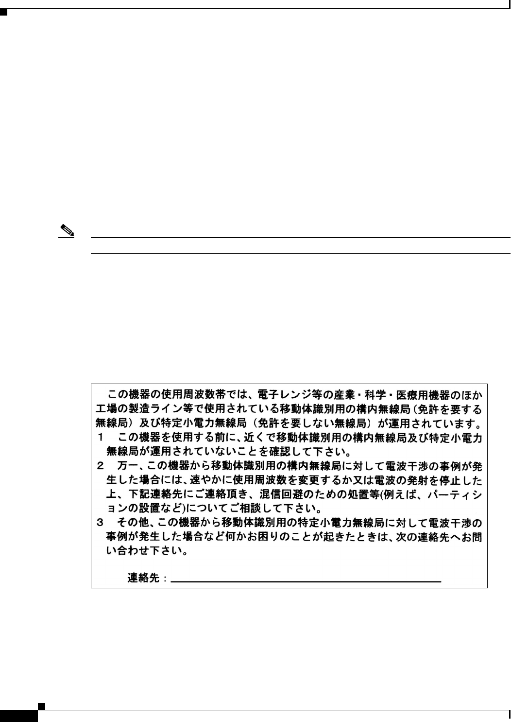
Draft Copy - CISCO CONFIDENTIAL
B-6
Cisco Aironet 1200 Series Access Point Hardware Installation Guide
OL-2155-02
Appendix B Declarations of Conformity and Regulatory Information
Declaration of Conformity for RF Exposure
Declaration of Conformity for RF Exposure
The radio module has been evaluated under FCC Bulletin OET 65C and found compliant to the
requirements as set forth in CFR 47 Sections 2.1091, 2.1093, and 15.247 (b) (4) addressing RF Exposure
from radio frequency devices. For antennas AIR-ANT4121 and AIR-ANT1949, the equipment should
be positioned more than 2 m (39.4 in) from your body or nearby persons. All other approved antennas
(2.4 GHz and 5 GHz) should be installed more than 20 cm (7.9 in) from your body or nearby persons.
The access point (with 5 GHz integrated antenna) must be installed to maintain a minimum 30 cm
(11.8 in) co-located separation distance from other FCC approved indoor/outdoor antennas used with the
access point. Any antennas or transmitters not approved by the FCC cannot be co-located with the access
point antennas. The access point’s co-located 2.4 GHz (2.2 dBi) and 5 GHz integrated antennas support
a minimum separation distance of 10 cm (3.9 in) and are compliant with the applicable FCC RF exposure
limit when transmitting simultaneously.
Note Dual antennas used for diversity operation are not considered co-located.
Guidelines for Operating Cisco Aironet Access Points in Japan
This section provides guidelines for avoiding interference when operating Cisco Aironet access points
in Japan. These guidelines are provided in both Japanese and English.
Japanese Translation
03-5549-6500
43768

Draft Copy - CISCO CONFIDENTIAL
B-7
Cisco Aironet 1200 Series Access Point Hardware Installation Guide
OL-2155-02
Appendix B Declarations of Conformity and Regulatory Information
Guidelines for Operating Cisco Aironet Access Points in Japan
English Translation
This equipment operates in the same frequency bandwidth as industrial, scientific, and medical devices
such as microwave ovens and mobile object identification (RF-ID) systems (licensed premises radio
stations and unlicensed specified low-power radio stations) used in factory production lines.
1. Before using this equipment, make sure that no premises radio stations or specified low-power radio
stations of RF-ID are used in the vicinity.
2. If this equipment causes RF interference to a premises radio station of RF-ID, promptly change the
frequency or stop using the device; contact the number below and ask for recommendations on
avoiding radio interference, such as setting partitions.
3. If this equipment causes RF interference to a specified low-power radio station of RF-ID, contact
the number below.
Contact Number: 03-5549-6500

Draft Copy - CISCO CONFIDENTIAL
B-8
Cisco Aironet 1200 Series Access Point Hardware Installation Guide
OL-2155-02
Appendix B Declarations of Conformity and Regulatory Information
Guidelines for Operating Cisco Aironet Access Points in Japan

C-1
Cisco Aironet 1200 Series Access Point Hardware Installation Guide
OL-2155-02
APPENDIX
C
Console Cable Pinouts
This appendix identifies the pinouts for the serial console cable that connects to the access point’s serial
console port. The appendix contains the following sections:
Overview, page C-2
Console Port Signals and Pinouts, page C-2

Draft Copy - CISCO CONFIDENTIAL
C-2
Cisco Aironet 1200 Series Access Point Hardware Installation Guide
OL-2155-02
Appendix C Console Cable Pinouts
Overview
Overview
The access point requires a special serial cable that connects the access point serial console port (RJ-45
connector) to your PC’s COM port (DB-9 connector). This cable can be purchased from Cisco (part
number AIR-CONCAB1200) or can be built using the pinouts in this appendix.
Console Port Signals and Pinouts
Use the console RJ-45 to DB-9 serial cable to connect the access point’s console port to the COM port
of your PC running a terminal emulation program.
Note Both the Ethernet and console ports use RJ-45 connectors. Be careful to avoid accidently connecting the
serial cable to the Ethernet port connector.
Table C-1 lists the signals and pinouts for the console RJ-45 to DB-9 serial cable.
1. NC indicates not connected.
Table C-1 Signals and Pinouts for a Console RJ-45 to DB-9 Serial Cable
Console Port PC COM Port
RJ-45 DB-9
Pins Signals1Pins Signals
- - 9 RI
1NC 8CTS
2NC 7DSR
3 TXD 6 RXD
4 GND 5 GND
5 GND 4 GND
6 RXD 3 TXD
7NC 2DTR
8NC 1RTS

GL-1
Cisco Aironet Wireless LAN Client Adapters Installation and Configuration Guide for Mac OS
OL-1377-02
GLOSSARY
802.11 The IEEE standard that specifies carrier sense media access control and physical
layer specifications for 1- and 2-megabit-per-second (Mbps) wireless LANs
operating in the 2.4 GHz band.
802.11a The IEEE standard that specifies carrier sense media access control and physical
layer specifications for wireless LANs operating in the 5-GHz frequency band.
802.11b The IEEE standard that specifies carrier sense media access control and physical
layer specifications for 5.5 and 11 Mbps wireless LANs operating in the
2.4-GHz frequency band.
A
Access Point A wireless LAN data transceiver that uses radio waves to connect a wired
network with wireless stations.
Ad Hoc Network A wireless network composed of stations without Access Points.
Antenna Gain The gain of an antenna is a measure of the antenna’s ability to direct or focus
radio energy over a region of space. High gain antennas have a more focused
radiation pattern in a specific direction.
Associated A station is configured properly to allow it to wirelessly communicate with an
Access Point.
B
Beacon A wireless LAN packet that signals the availability and presence of the wireless
device. Beacon packets are sent by access points and base stations; however,
client radio cards send beacons when operating in computer to computer (Ad
Hoc) mode.
BOOTP Boot Protocol. A protocol used for the static assignment of IP addresses to
devices on the network.
BPSK A modulation technique used by IEEE 802.11b-compliant wireless LANs for
transmission at 1 Mbps.
Broadcast Packet A single data message (packet) sent to all addresses on the same subnet.

Glossary
GL-2
Cisco Aironet Wireless LAN Client Adapters Installation and Configuration Guide for Mac OS
OL-1377-02
C
CCK Complementary code keying. A modulation technique used by IEEE
802.11b-compliant wireless LANs for transmission at 5.5 and 11 Mbps.
Cell The area of radio range or coverage in which the wireless devices can
communicate with the base station. The size of the cell depends upon the speed
of the transmission, the type of antenna used, and the physical environment, as
well as other factors.
Client A radio device that uses the services of an Access Point to communicate
wirelessly with other devices on a local area network.
CSMA Carrier sense multiple access. A wireless LAN media access method specified
by the IEEE 802.11 specification.
D
Data Rates The range of data transmission rates supported by a device. Data rates are
measured in megabits per second (Mbps).
dBi A ratio of decibels to an isotropic antenna that is commonly used to measure
antenna gain. The greater the dBi value, the higher the gain, and the more acute
the angle of coverage.
DHCP Dynamic host configuration protocol. A protocol available with many operating
systems that automatically issues IP addresses within a specified range to
devices on the network. The device retains the assigned address for a specific
administrator-defined period.
Dipole A type of low-gain (2.2-dBi) antenna consisting of two (often internal) elements.
Domain Name The text name that refers to a grouping of networks or network resources based
on organization-type or geography; for example: name.com—commercial;
name.edu—educational; name.gov—government; ISPname.net—network
provider (such as an ISP); name.ar—Argentina; name.au—Australia; and so on.
DNS Domain Name System server. A server that translates text names into IP
addresses. The server maintains a database of host alphanumeric names and their
corresponding IP addresses.
DSSS Direct sequence spread spectrum. A type of spread spectrum radio transmission
that spreads its signal continuously over a wide frequency band.

Glossary
GL-3
Cisco Aironet Wireless LAN Client Adapters Installation and Configuration Guide for Mac OS
OL-1377-02
E
EAP Extensible Authentication Protocol. An optional IEEE 802.1x security feature
ideal for organizations with a large user base and access to an EAP-enabled
Remote Authentication Dial-In User Service (RADIUS) server.
Ethernet The most widely used wired local area network. Ethernet uses carrier sense
multiple access (CSMA) to allow computers to share a network and operates at
10, 100, or 1000 Mbps, depending on the physical layer used.
F
File Server A repository for files so that a local area network can share files, mail, and
programs.
Firmware Software that is programmed on a memory chip.
G
Gateway A device that connects two otherwise incompatible networks together.
GHz Gigahertz. One billion cycles per second. A unit of measure for frequency.
I
IEEE Institute of Electrical and Electronic Engineers. A professional society serving
electrical engineers through its publications, conferences, and standards
development activities. The body responsible for the Ethernet 802.3 and wireless
LAN 802.11 specifications.
Infrastructure The wired Ethernet network.
IP Address The Internet Protocol (IP) address of a station.
IP Subnet Mask The number used to identify the IP subnetwork, indicating whether the IP
address can be recognized on the LAN or if it must be reached through a
gateway. This number is expressed in a form similar to an IP address; for
example: 255.255.255.0.
Isotropic An antenna that radiates its signal 360 degrees both vertically and horizontally
in a perfect sphere.

Glossary
GL-4
Cisco Aironet Wireless LAN Client Adapters Installation and Configuration Guide for Mac OS
OL-1377-02
M
MAC Media Access Control address. A unique 48-bit number used in Ethernet data
packets to identify an Ethernet device, such as an access point or your client
adapter.
Modulation Any of several techniques for combining user information with a transmitter’s
carrier signal.
Multipath The echoes created as a radio signal bounces off of physical objects.
Multicast Packet A single data message (packet) sent to multiple addresses.
O
Omni-directional This typically refers to a primarily circular antenna radiation pattern.
Orthogonal
Frequency Division
Multiplex (OFDM)
A modulation technique used by IEEE 802.11a-compliant wireless LANs for
transmission at 6, 9, 12, 18, 24, 36, 48, and 54 Mbps.
P
Packet A basic message unit for communication across a network. A packet usually includes routing
information, data, and sometimes error detection information.
Q
Quadruple Phase
Shift Keying A modulation technique used by IEEE 802.11b-compliant wireless LANs for
transmission at 2 Mbps.
R
Range A linear measure of the distance that a transmitter can send a signal.
Receiver Sensitivity A measurement of the weakest signal a receiver can receive and still correctly
translate it into data.
RF Radio frequency. A generic term for radio-based technology.

Glossary
GL-5
Cisco Aironet Wireless LAN Client Adapters Installation and Configuration Guide for Mac OS
OL-1377-02
Roaming A feature of some Access Points that allows users to move through a facility
while maintaining an unbroken connection to the LAN.
RP-TNC A connector type unique to Cisco Aironet radios and antennas. Part 15.203 of
the FCC rules covering spread spectrum devices limits the types of antennas that
may be used with transmission equipment. In compliance with this rule, Cisco
Aironet, like all other wireless LAN providers, equips its radios and antennas
with a unique connector to prevent attachment of non-approved antennas to
radios.
S
Spread Spectrum A radio transmission technology that spreads the user information over a much
wider bandwidth than otherwise required in order to gain benefits such as
improved interference tolerance and unlicensed operation.
SSID Service Set Identifier (also referred to as Radio Network Name). A unique
identifier used to identify a radio network and which stations must use to be able
to communicate with each other or to an access point. The SSID can be any
alphanumeric entry up to a maximum of 32 characters.
T
Transmit Power The power level of radio transmission.
U
UNII Unlicensed National Information Infrastructure—regulations for UNII devices
operating in the 5.15 to 5.35 GHz and 5.725 to 5.825 GHz frequency bands.
UNII-1 Regulations for UNII devices operating in the 5.15 to 5.25 GHz frequency band.
UNII-2 Regulations for UNII devices operating in the 5.25 to 5.35 GHz frequency band.
UNII-3 Regulations for UNII devices operating in the 5.725 to 5.825 GHz frequency
band.
Unicast Packet A single data message (packet) sent to a specific IP address.
W
WEP Wired Equivalent Privacy. An optional security mechanism defined within the
802.11 standard designed to make the link integrity of wireless devices equal to
that of a cable.
Workstation A computing device with an installed client adapter.

Glossary
GL-6
Cisco Aironet Wireless LAN Client Adapters Installation and Configuration Guide for Mac OS
OL-1377-02

Draft Copy - CISCO CONFIDENTIAL
IN-1
Cisco Aironet 1200 Series Access Point Hardware Installation Guide
OL-2155-02
INDEX
A
access point/root 3-7, 3-8, 3-11, 3-12
antenna
connectors 1-4, 1-11
safety guidelines 2-2
warnings A-1
audience vii
B
basic settings
checking 7-3
default 3-13
entering 3-6, 3-9
BOOTP 3-7, 3-10
C
caution viii
central unit 1-9
Cisco TAC 7-1
client/non-root 3-7, 3-8, 3-11, 3-12
configuration
basic 3-1
server 3-7, 3-10
summary 3-2
connecting cables 2-10
connectors 1-4, 1-10, 1-11, 3-9
console port 1-4, 3-9, C-2
conventions, document viii
coverage, minimal overlap 2-5
D
data rates 1-11, 2-6
declarations of conformity B-1
default
configuration, resetting 7-4
gateway 3-7, 3-11
settings 3-13
DHCP 3-2, 3-7, 3-10
documentation
conventions viii
related publications viii
E
ensure compatibility setting 3-8, 3-12
environmental air space 1-4
environmental conditions 2-6
Ethernet indicator 7-2
Ethernet port 1-4
express setup 3-2, 3-6
extended temperature range 2-4
F
FCC Declaration of Conformity B-2
FCC Safety Compliance 2-2
feedback x
fire resistance 1-4
frequency range 1-10

Draft Copy - CISCO CONFIDENTIAL
Index
IN-2
Cisco Aironet 1200 Series Access Point Hardware Installation Guide
OL-2155-02
G
guidelines 2-4
I
indicators 1-5, 7-2
inline power 1-3
input power 1-10
installation guidelines 2-4
Internet browser 3-6
IP address, finding and setting 3-3
IPSU 3-3
L
LAN transceiver 1-1
LED indicators
Ethernet 7-2
radio traffic 7-2
status 7-2
M
MAC 3-4, 3-5
modulation 1-11
N
network configurations 1-7
O
obtaining
documentation viii, x
technical assistance x
operating temperature 1-10
optimize radio network 3-8, 3-11, 3-12
P
package contents 2-7
password reset 7-4
pinouts, serial cable C-2
ports, Ethernet and serial 1-4
power
connecting 2-9
injector 2-9
inline 1-3
input 1-10
output 1-10
power injector 1-3
R
radio
indicator 7-2
range 1-11, 3-8, 3-11, 3-12
regulatory B-1
related publications viii
repeater/non-root 3-7, 3-8, 3-11, 3-12
repeater operation 1-8
RF exposure B-6
RJ-45 connectors 1-3
roaming 2-5, 2-6
role, radio network 3-7, 3-8, 3-11, 3-12, 3-13
root unit 1-7
S
safety warnings, translated A-1
seamless roaming 2-5
serial
cable 1-4, 3-9, C-2
Cisco cable 7-4, C-2
connecting cable 3-9
console port 3-9
interface 3-9

Draft Copy - CISCO CONFIDENTIAL
Index
IN-3
Cisco Aironet 1200 Series Access Point Hardware Installation Guide
OL-2155-02
port 1-4
site survey 2-6
size 1-10
SNMP 3-8, 3-12, 3-13
specifications 1-10
SSID
before you start 3-2
default value 3-13
troubleshooting 7-3
using an Internet browser 3-7, 3-8
using the console port 3-11, 3-12
status indicators 1-10, 7-2
storage temperature 1-10
subnet mask 3-7, 3-11
system name 3-13
T
TAC 7-1
technical assistance x
Technical Assistance Center (TAC) xi
temperature
operating 1-10
storage 1-10
terminal emulator 3-2, 3-9
terminal type 3-13
throughput 3-8, 3-11, 3-12
troubleshooting 7-1
U
Unlicensed National Information Infrastructure
(UNII) 1-2
unpacking 2-6
V
voltage range 1-10
W
warnings viii, 2-3, A-1
web site
Cisco ix
Cisco Software Center 3-3
Technical Assistance Center (TAC) xi
weight 1-10
WEP key 7-4

Draft Copy - CISCO CONFIDENTIAL
Index
IN-4
Cisco Aironet 1200 Series Access Point Hardware Installation Guide
OL-2155-02