Cisco Systems 102047P Wireless Ethernet Bridge User Manual 1400higb
Cisco Systems Inc Wireless Ethernet Bridge 1400higb
UserManual.wiki
>
Cisco Systems
>
102047P User Manual
User Manual
Navigation menu
Upload a User Manual
Namespaces
Wiki Guide
HTML
PDF
Info
Views
User Manual
Discussion / Help
Navigation
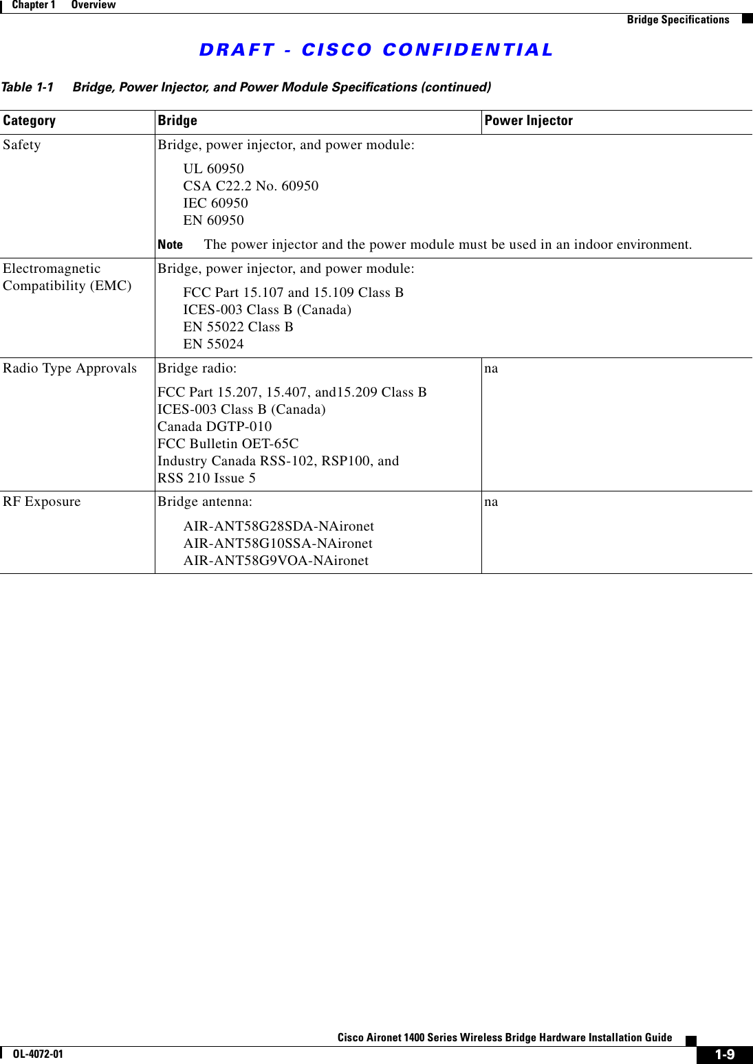
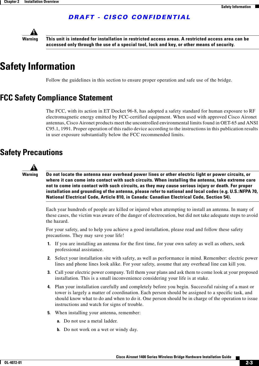
![DRAFT - CISCO CONFIDENTIALixCisco Aironet 1400 Series Wireless Bridge Hardware Installation GuideOL-4072-01PrefaceRelated PublicationsRelated PublicationsFor more information about bridges and related products, refer to the following publications:•Quick Start Guide: Cisco Aironet 1400 Series Wireless Bridge describes the bridge, system components, and how to obtain bridge documentation. This document is included in the shipping box with your bridge.•Cisco Aironet 1400 Series Wireless Bridge Software Configuration Guide describes the bridge’s management system and explains how to configure the bridge. This document is available on the Cisco CCO web site at the following URL:TBD•Cisco Aironet 1400 Series Wireless Bridge Mounting Instructions that was shipped with your bridge provides detailed instructions for mounting the bridge and aligning the antenna .•Cisco IOS Command Reference for Cisco Aironet Access Points and Bridges describes the IOS commands supported by Cisco Aironet access points and bridges. This document is available on the Cisco CCO web site at the following URL:TBDAvvertenzaQuesto simbolo di avvertenza indica un pericolo. Si è in una situazione che può causare infortuni. Prima di lavorare su qualsiasi apparecchiatura, occorre conoscere i pericoli relativi ai circuiti elettrici ed essere al corrente delle pratiche standard per la prevenzione di incidenti. La traduzione delle avvertenze riportate in questa pubblicazione si trova nell’appendice, “Translated Safety Warnings” (Traduzione delle avvertenze di sicurezza).AdvarselDette varselsymbolet betyr fare. Du befinner deg i en situasjon som kan føre til personskade. Før du utfører arbeid på utstyr, må du være oppmerksom på de faremomentene som elektriske kretser innebærer, samt gjøre deg kjent med vanlig praksis når det gjelder å unngå ulykker. (Hvis du vil se oversettelser av de advarslene som finnes i denne publikasjonen, kan du se i vedlegget "Translated Safety Warnings" [Oversatte sikkerhetsadvarsler].)AvisoEste símbolo de aviso indica perigo. Encontra-se numa situação que lhe poderá causar danos fisicos. Antes de começar a trabalhar com qualquer equipamento, familiarize-se com os perigos relacionados com circuitos eléctricos, e com quaisquer práticas comuns que possam prevenir possíveis acidentes. (Para ver as traduções dos avisos que constam desta publicação, consulte o apêndice “Translated Safety Warnings” - “Traduções dos Avisos de Segurança”).¡Advertencia!Este símbolo de aviso significa peligro. Existe riesgo para su integridad física. Antes de manipular cualquier equipo, considerar los riesgos que entraña la corriente eléctrica y familiarizarse con los procedimientos estándar de prevención de accidentes. (Para ver traducciones de las advertencias que aparecen en esta publicación, consultar el apéndice titulado “Translated Safety Warnings.”)Varning!Denna varningssymbol signalerar fara. Du befinner dig i en situation som kan leda till personskada. Innan du utför arbete på någon utrustning måste du vara medveten om farorna med elkretsar och känna till vanligt förfarande för att förebygga skador. (Se förklaringar av de varningar som förekommer i denna publikation i appendix "Translated Safety Warnings" [Översatta säkerhetsvarningar].)](https://usermanual.wiki/Cisco-Systems/102047P/User-Guide-323927-Page-9.png)
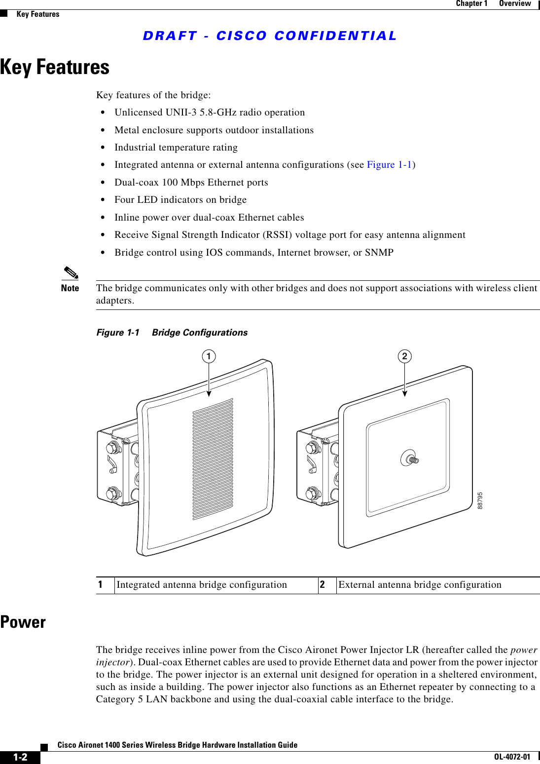
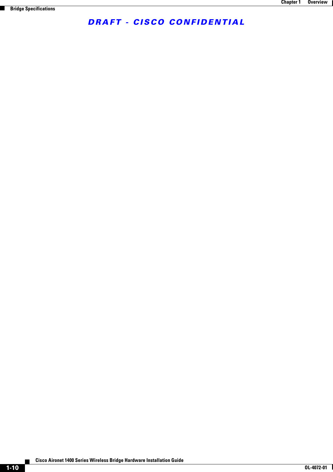
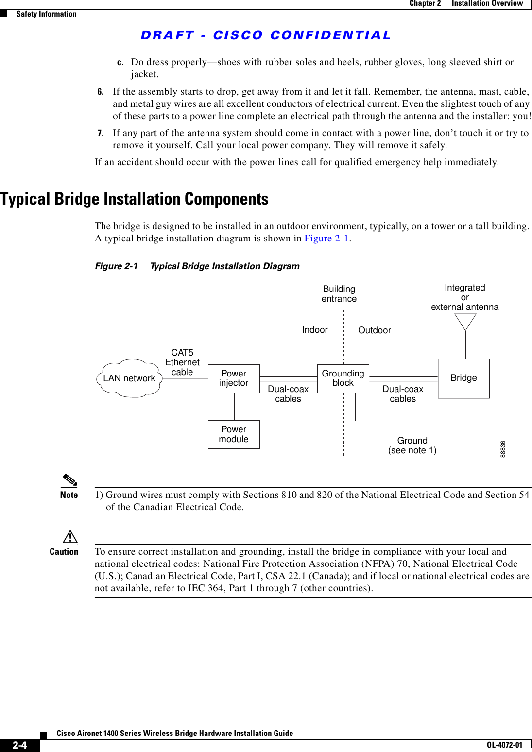
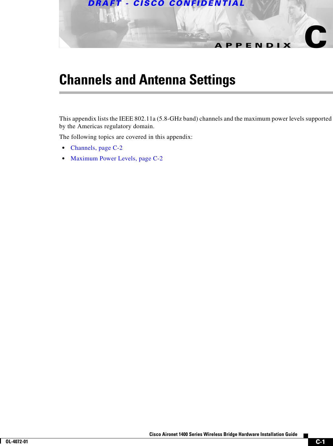
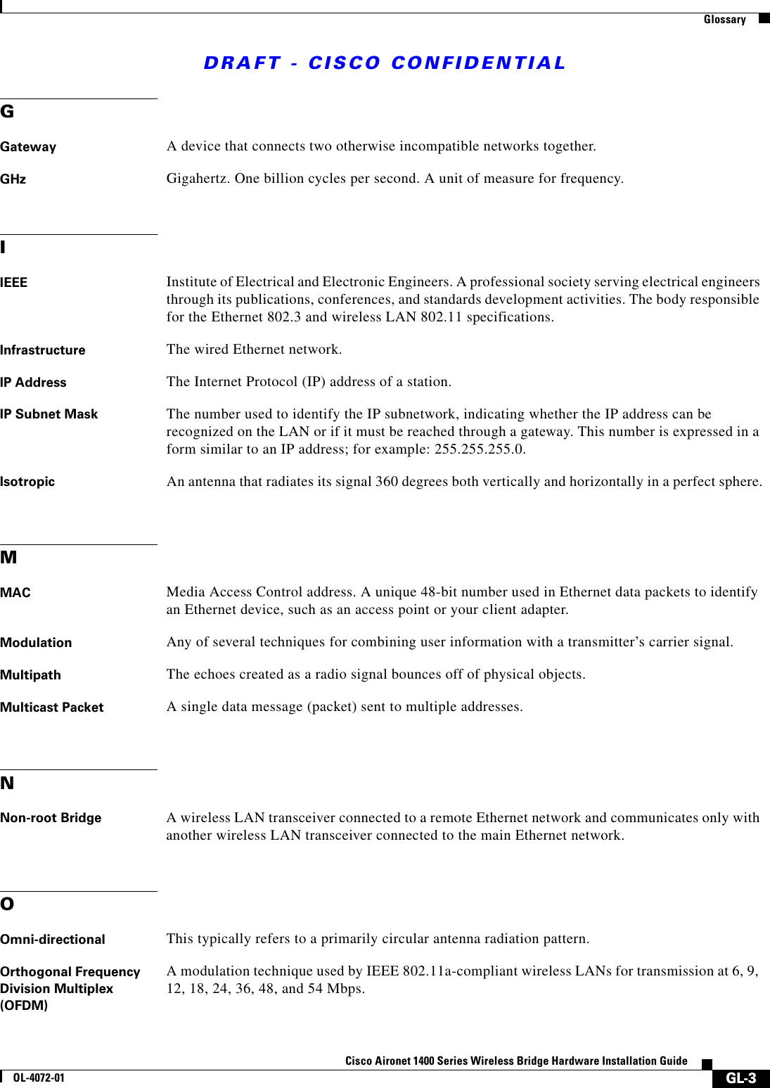
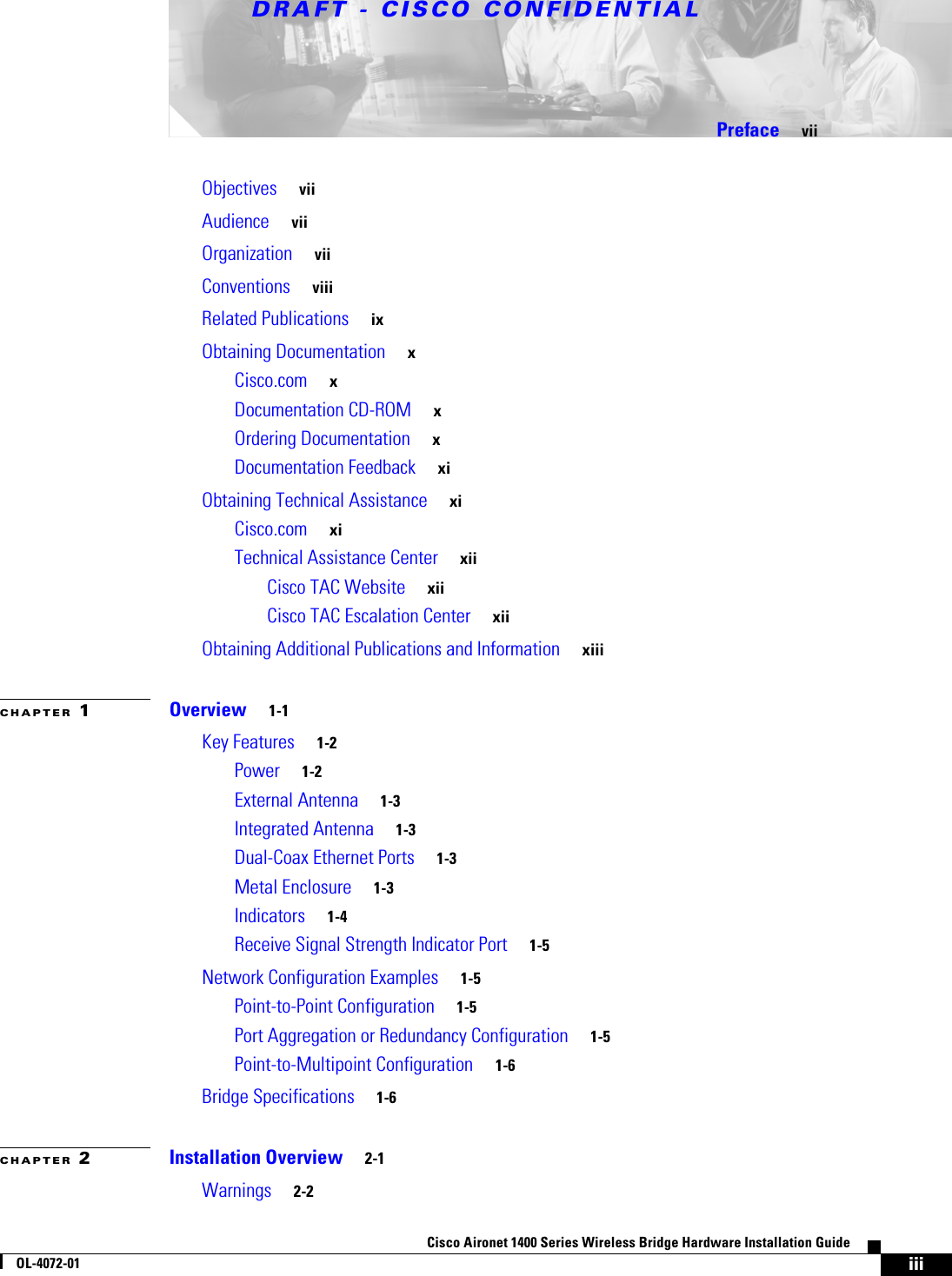
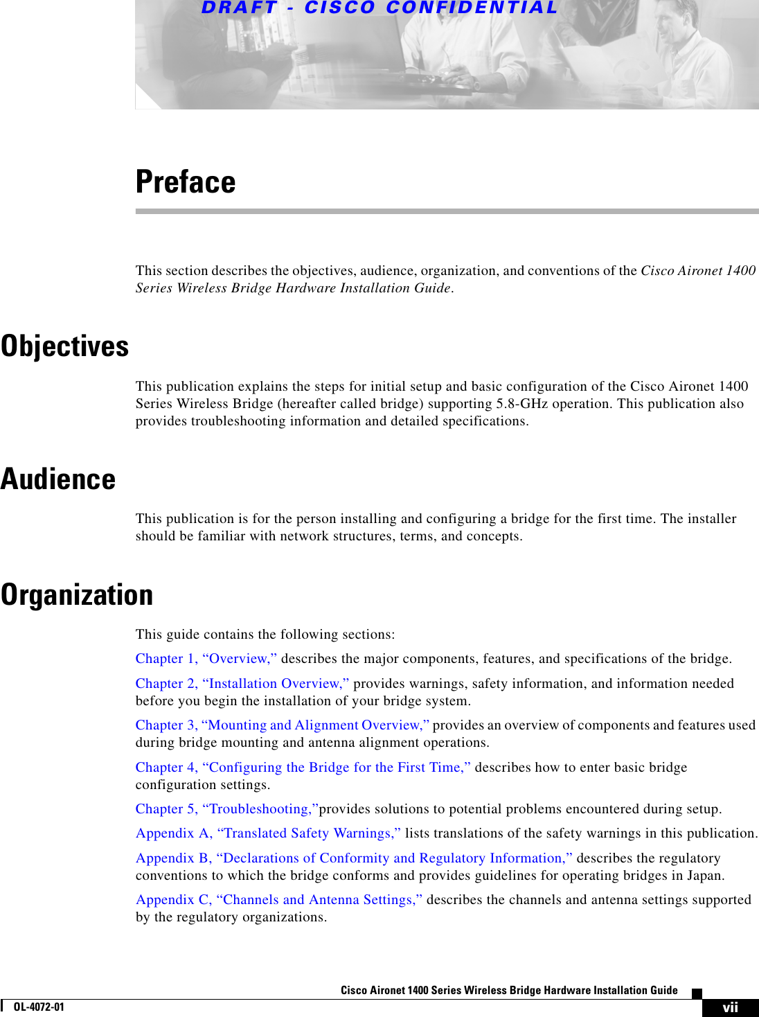
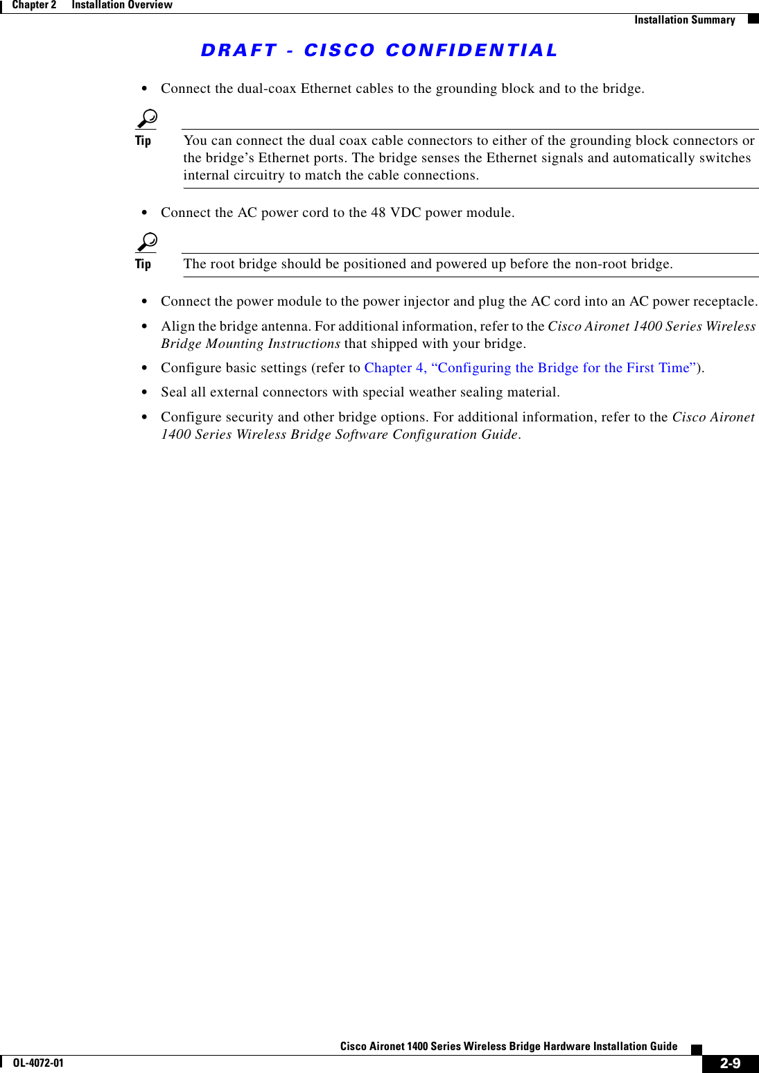
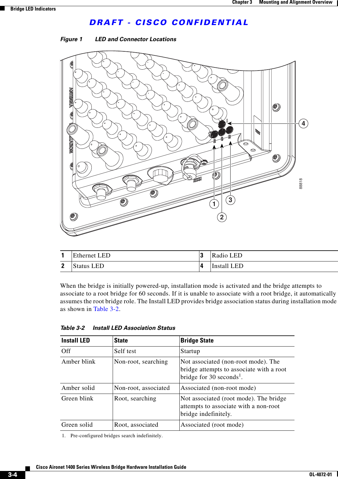
![DRAFT - CISCO CONFIDENTIAL2-6Cisco Aironet 1400 Series Wireless Bridge Hardware Installation GuideOL-4072-01Chapter 2 Installation OverviewBefore Beginning the InstallationPackage ContentsEach bridge package contains the following items:•Bridge unit•Power injector unit (with mounting screws and wall anchors)•Power module and AC power cord (with mounting screws and wall anchors)•Two dual-coax cables [20 ft (6.1 m) and 50 ft (15.2 m)]•Mounting kit and hardware –Multi-function mount (consisting of two bridge brackets and one tower or mast bracket) –Two tower clamps (U-bolts) with four nuts, washers, and lock washers–Four bolts and washers for securing the bridge brackets to the tower or mast bracket–Four bolts, washers, and lock washers for securing the bridge brackets to the bridge•Grounding Block and mounting screws•Ground lug for the bridge with screws•Weatherproofing kit (consisting of Coax Seal and anti-corrosion gel)•Quick Start Guide: Cisco Aironet 1400 Series Wireless Bridge•Cisco Aironet 1400 Series Wireless Bridge Mounting Instructions•Cisco product registration and Cisco documentation feedback cardsBefore Beginning the InstallationBefore you begin the installation process, please carefully review the following list of figures to become familiar with the system components, connectors, indicators, cables, system interconnection, and grounding:•Bridge block diagram (Figure 2-1)•Bridge layout (Figure 2-2)•Power injector layout (Figure 2-3)•Power module (Figure 2-4)•Grounding block (Figure 2-5)](https://usermanual.wiki/Cisco-Systems/102047P/User-Guide-323927-Page-30.png)

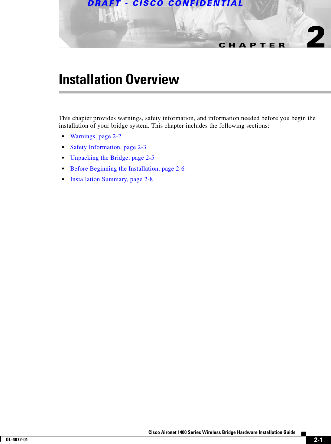
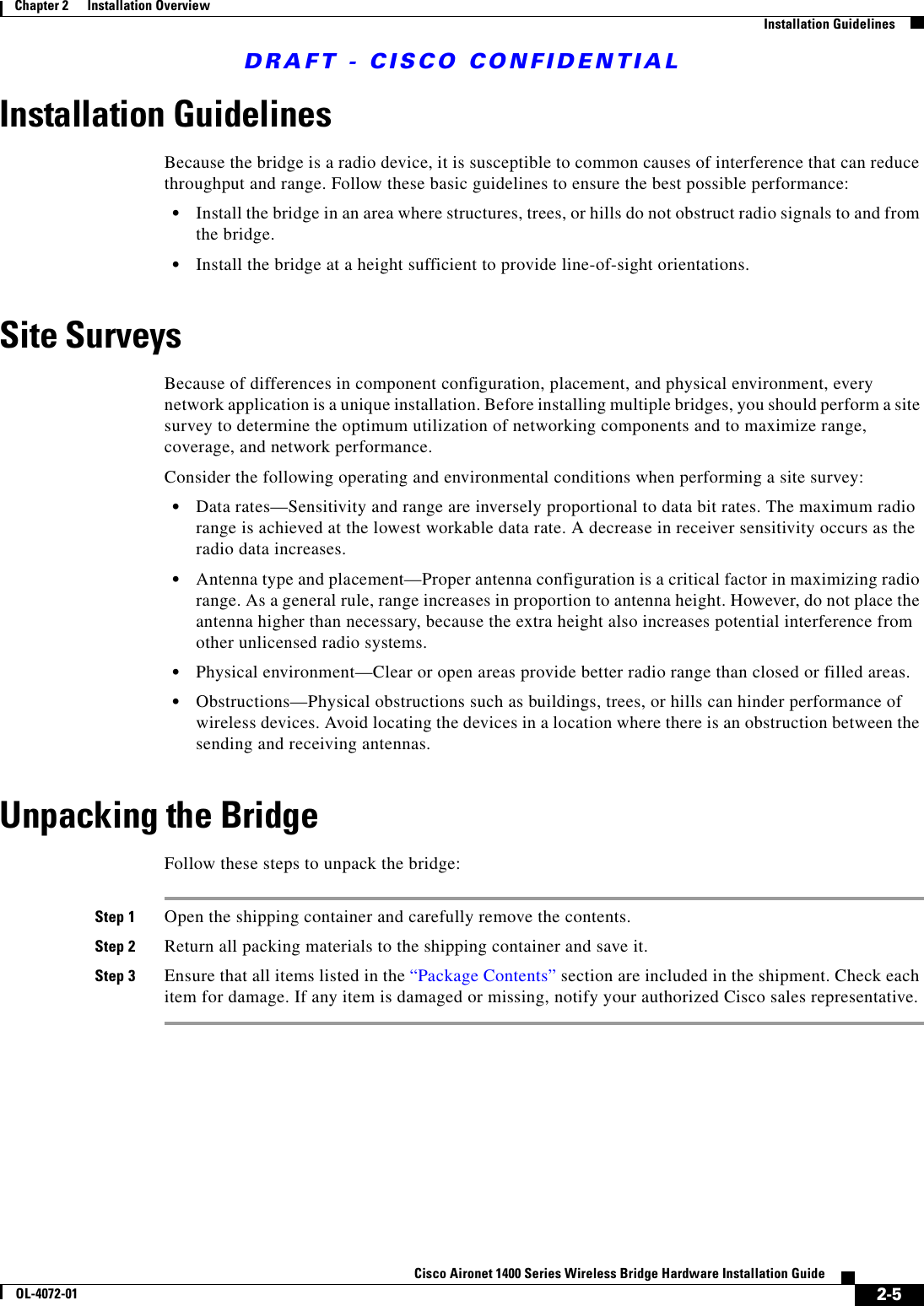
![DRAFT - CISCO CONFIDENTIALA-2Cisco Aironet 1400 Series Wireless Bridge Hardware Installation GuideOL-4072-01Appendix A Translated Safety WarningsWarning DefinitionWarning DefinitionWarningThis warning symbol means danger. You are in a situation that could cause bodily injury. Before you work on any equipment, be aware of the hazards involved with electrical circuitry and be familiar with standard practices for preventing accidents. (To see translations of the warnings that appear in this publication, refer to the appendix “Translated Safety Warnings.”)WaarschuwingDit waarschuwingssymbool betekent gevaar. U verkeert in een situatie die lichamelijk letsel kan veroorzaken. Voordat u aan enige apparatuur gaat werken, dient u zich bewust te zijn van de bij elektrische schakelingen betrokken risico’s en dient u op de hoogte te zijn van standaard maatregelen om ongelukken te voorkomen. (Voor vertalingen van de waarschuwingen die in deze publicatie verschijnen, kunt u het aanhangsel “Translated Safety Warnings” (Vertalingen van veiligheidsvoorschriften) raadplegen.)VaroitusTämä varoitusmerkki merkitsee vaaraa. Olet tilanteessa, joka voi johtaa ruumiinvammaan. Ennen kuin työskentelet minkään laitteiston parissa, ota selvää sähkökytkentöihin liittyvistä vaaroista ja tavanomaisista onnettomuuksien ehkäisykeinoista. (Tässä julkaisussa esiintyvien varoitusten käännökset löydät liitteestä "Translated Safety Warnings" (käännetyt turvallisuutta koskevat varoitukset).)AttentionCe symbole d’avertissement indique un danger. Vous vous trouvez dans une situation pouvant en-traîner des blessures. Avant d’accéder à cet équipement, soyez conscient des dangers posés par les circuits électriques et familiarisez-vous avec les procédures courantes de prévention des ac-cidents. Pour obtenir les traductions des mises en garde figurant dans cette publication, veuillez consulter l’annexe intitulée «Translated Safety Warnings » (Traduction des avis de sécurité).WarnungDieses Warnsymbol bedeutet Gefahr. Sie befinden sich in einer Situation, die zu einer Körperver-letzung führen könnte. Bevor Sie mit der Arbeit an irgendeinem Gerät beginnen, seien Sie sich der mit elektrischen Stromkreisen verbundenen Gefahren und der Standardpraktiken zur Vermeidung von Unfällen bewußt. (Übersetzungen der in dieser Veröffentlichung enthaltenen Warnhinweise finden Sie im Anhang mit dem Titel “Translated Safety Warnings” (Übersetzung der Warnhin-weise).)AvvertenzaQuesto simbolo di avvertenza indica un pericolo. Si è in una situazione che può causare infortuni. Prima di lavorare su qualsiasi apparecchiatura, occorre conoscere i pericoli relativi ai circuiti elettrici ed essere al corrente delle pratiche standard per la prevenzione di incidenti. La traduz-ione delle avvertenze riportate in questa pubblicazione si trova nell’appendice, “Translated Safe-ty Warnings” (Traduzione delle avvertenze di sicurezza).AdvarselDette varselsymbolet betyr fare. Du befinner deg i en situasjon som kan føre til personskade. Før du utfører arbeid på utstyr, må du være oppmerksom på de faremomentene som elektriske kretser innebærer, samt gjøre deg kjent med vanlig praksis når det gjelder å unngå ulykker. (Hvis du vil se oversettelser av de advarslene som finnes i denne publikasjonen, kan du se i vedlegget "Trans-lated Safety Warnings" [Oversatte sikkerhetsadvarsler].)AvisoEste símbolo de aviso indica perigo. Encontra-se numa situação que lhe poderá causar danos fi-sicos. Antes de começar a trabalhar com qualquer equipamento, familiarize-se com os perigos relacionados com circuitos eléctricos, e com quaisquer práticas comuns que possam prevenir possíveis acidentes. (Para ver as traduções dos avisos que constam desta publicação, consulte o apêndice “Translated Safety Warnings” - “Traduções dos Avisos de Segurança”).](https://usermanual.wiki/Cisco-Systems/102047P/User-Guide-323927-Page-66.png)
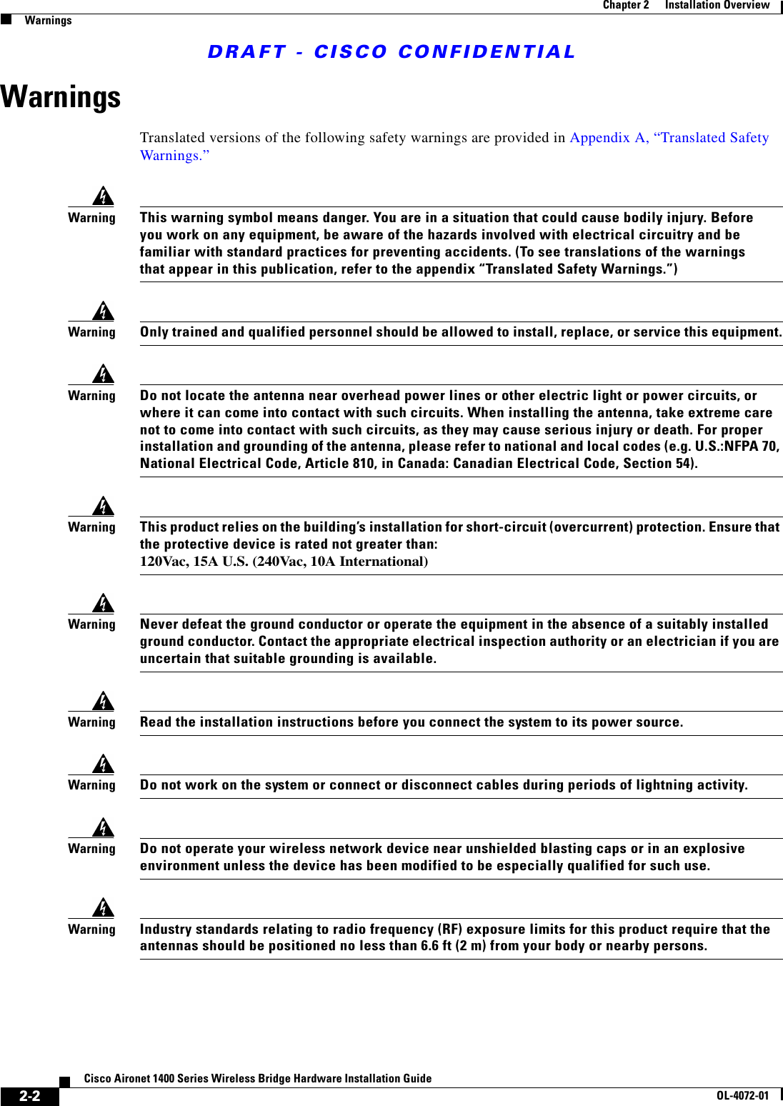
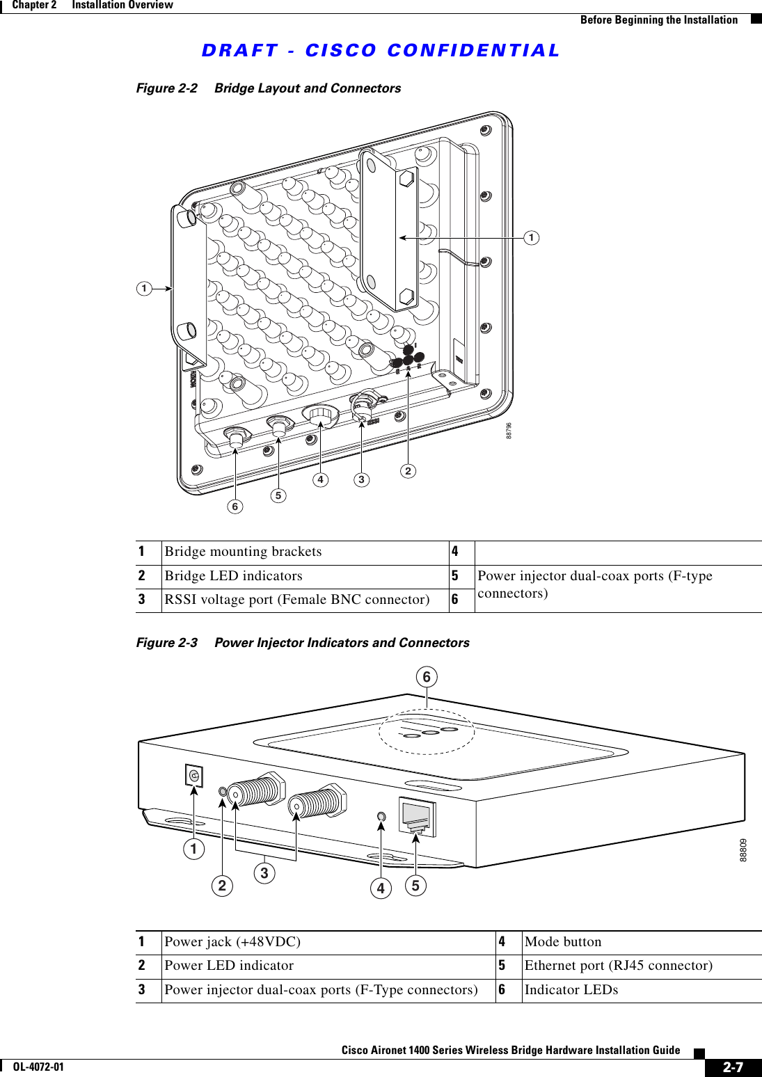
![DRAFT - CISCO CONFIDENTIALA-3Cisco Aironet 1400 Series Wireless Bridge Hardware Installation GuideOL-4072-01Appendix A Translated Safety WarningsInstallation WarningInstallation Warning¡Advertencia!Este símbolo de aviso significa peligro. Existe riesgo para su integridad física. Antes de manipu-lar cualquier equipo, considerar los riesgos que entraña la corriente eléctrica y familiarizarse con los procedimientos estándar de prevención de accidentes. (Para ver traducciones de las ad-vertencias que aparecen en esta publicación, consultar el apéndice titulado “Translated Safety Warnings.”)Varning!Denna varningssymbol signalerar fara. Du befinner dig i en situation som kan leda till personska-da. Innan du utför arbete på någon utrustning måste du vara medveten om farorna med elkretsar och känna till vanligt förfarande för att förebygga skador. (Se förklaringar av de varningar som förekommer i denna publikation i appendix "Translated Safety Warnings" [Översatta säkerhets-varningar].)WarningOnly trained and qualified personnel should be allowed to install, replace, or service this equipment.WaarschuwingDeze apparatuur mag alleen worden geïnstalleerd, vervangen of hersteld door bevoegd geschoold personeel.VaroitusTämän laitteen saa asentaa, vaihtaa tai huoltaa ainoastaan koulutettu ja laitteen tunteva henkilökunta.AttentionIl est vivement recommandé de confier l'installation, le remplacement et la maintenance de ces équipements à des personnels qualifiés et expérimentés.WarnungDas Installieren, Ersetzen oder Bedienen dieser Ausrüstung sollte nur geschultem, qualifiziertem Personal gestattet werden.Figyelem!A berendezést csak szakképzett személyek helyezhetik üzembe, cserélhetik és tarthatják karban.AvvertenzaQuesto apparato può essere installato, sostituito o mantenuto unicamente da un personale competente.AdvarselBare opplært og kvalifisert personell skal foreta installasjoner, utskiftninger eller service på dette utstyret.AvisoApenas pessoal treinado e qualificado deve ser autorizado a instalar, substituir ou fazer a revisão deste equipamento.¡Advertencia!Solamente el personal calificado debe instalar, reemplazar o utilizar este equipo.Varning!Endast utbildad och kvalificerad personal bör få tillåtelse att installera, byta ut eller reparera denna utrustning.](https://usermanual.wiki/Cisco-Systems/102047P/User-Guide-323927-Page-67.png)