Cisco Systems 102051 802.11 a/g PCI Adapter User Manual winicgkhb
Cisco Systems Inc 802.11 a/g PCI Adapter winicgkhb
Contents
- 1. User Manual
- 2. User Manual 1
- 3. User Manual 2
User Manual

BETA DRAFT - CISCO CONFIDENTIAL
Corporate Headquarters
Cisco Systems, Inc.
170 West Tasman Drive
San Jose, CA 95134-1706
USA
http://www.cisco.com
Tel: 408 526-4000
800 553-NETS (6387)
Fax: 408 526-4100
Cisco Aironet 802.11a/b/g Wireless LAN Client
Adapters (CB21AG and PI21AG)
Installation and Configuration Guide
Customer Order Number:
Text Part Number: OL-4211-01
BETA DRAFT - CISCO CONFIDENTIAL
THE SPECIFICATIONS AND INFORMATION REGARDING THE PRODUCTS IN THIS MANUAL ARE SUBJECT TO CHANGE WITHOUT NOTICE. ALL
STATEMENTS, INFORMATION, AND RECOMMENDATIONS IN THIS MANUAL ARE BELIEVED TO BE ACCURATE BUT ARE PRESENTED WITHOUT
WARRANTY OF ANY KIND, EXPRESS OR IMPLIED. USERS MUST TAKE FULL RESPONSIBILITY FOR THEIR APPLICATION OF ANY PRODUCTS.
THE SOFTWARE LICENSE AND LIMITED WARRANTY FOR THE ACCOMPANYING PRODUCT ARE SET FORTH IN THE INFORMATION PACKET THAT
SHIPPED WITH THE PRODUCT AND ARE INCORPORATED HEREIN BY THIS REFERENCE. IF YOU ARE UNABLE TO LOCATE THE SOFTWARE LICENSE
OR LIMITED WARRANTY, CONTACT YOUR CISCO REPRESENTATIVE FOR A COPY.
The following information is for FCC compliance of Class A devices: This equipment has been tested and found to comply with the limits for a Class A digital device, pursuant
to part 15 of the FCC rules. These limits are designed to provide reasonable protection against harmful interference when the equipment is operated in a commercial
environment. This equipment generates, uses, and can radiate radio-frequency energy and, if not installed and used in accordance with the instruction manual, may cause
harmful interference to radio communications. Operation of this equipment in a residential area is likely to cause harmful interference, in which case users will be required
to correct the interference at their own expense.
The following information is for FCC compliance of Class B devices: The equipment described in this manual generates and may radiate radio-frequency energy. If it is not
installed in accordance with Cisco’s installation instructions, it may cause interference with radio and television reception. This equipment has been tested and found to
comply with the limits for a Class B digital device in accordance with the specifications in part 15 of the FCC rules. These specifications are designed to provide reasonable
protection against such interference in a residential installation. However, there is no guarantee that interference will not occur in a particular installation.
Modifying the equipment without Cisco’s written authorization may result in the equipment no longer complying with FCC requirements for Class A or Class B digital
devices. In that event, your right to use the equipment may be limited by FCC regulations, and you may be required to correct any interference to radio or television
communications at your own expense.
You can determine whether your equipment is causing interference by turning it off. If the interference stops, it was probably caused by the Cisco equipment or one of its
peripheral devices. If the equipment causes interference to radio or television reception, try to correct the interference by using one or more of the following measures:
• Turn the television or radio antenna until the interference stops.
• Move the equipment to one side or the other of the television or radio.
• Move the equipment farther away from the television or radio.
• Plug the equipment into an outlet that is on a different circuit from the television or radio. (That is, make certain the equipment and the television or radio are on circuits
controlled by different circuit breakers or fuses.)
Modifications to this product not authorized by Cisco Systems, Inc. could void the FCC approval and negate your authority to operate the product.
The Cisco implementation of TCP header compression is an adaptation of a program developed by the University of California, Berkeley (UCB) as part of UCB’s public
domain version of the UNIX operating system. All rights reserved. Copyright © 1981, Regents of the University of California.
NOTWITHSTANDING ANY OTHER WARRANTY HEREIN, ALL DOCUMENT FILES AND SOFTWARE OF THESE SUPPLIERS ARE PROVIDED “AS IS” WITH
ALL FAULTS. CISCO AND THE ABOVE-NAMED SUPPLIERS DISCLAIM ALL WARRANTIES, EXPRESSED OR IMPLIED, INCLUDING, WITHOUT
LIMITATION, THOSE OF MERCHANTABILITY, FITNESS FOR A PARTICULAR PURPOSE AND NONINFRINGEMENT OR ARISING FROM A COURSE OF
DEALING, USAGE, OR TRADE PRACTICE.
IN NO EVENT SHALL CISCO OR ITS SUPPLIERS BE LIABLE FOR ANY INDIRECT, SPECIAL, CONSEQUENTIAL, OR INCIDENTAL DAMAGES, INCLUDING,
WITHOUT LIMITATION, LOST PROFITS OR LOSS OR DAMAGE TO DATA ARISING OUT OF THE USE OR INABILITY TO USE THIS MANUAL, EVEN IF CISCO
OR ITS SUPPLIERS HAVE BEEN ADVISED OF THE POSSIBILITY OF SUCH DAMAGES.
CCIP, CCSP, the Cisco Arrow logo, the Cisco Powered Network mark, Cisco Unity, Follow Me Browsing, FormShare, and StackWise are trademarks of Cisco Systems, Inc.;
Changing the Way We Work, Live, Play, and Learn, and iQuick Study are service marks of Cisco Systems, Inc.; and Aironet, ASIST, BPX, Catalyst, CCDA, CCDP, CCIE,
CCNA, CCNP, Cisco, the Cisco Certified Internetwork Expert logo, Cisco IOS, the Cisco IOS logo, Cisco Press, Cisco Systems, Cisco Systems Capital, the Cisco Systems
logo, Empowering the Internet Generation, Enterprise/Solver, EtherChannel, EtherSwitch, Fast Step, GigaStack, Internet Quotient, IOS, IP/TV, iQ Expertise, the iQ logo, iQ
Net Readiness Scorecard, LightStream, MGX, MICA, the Networkers logo, Networking Academy, Network Registrar, Packet, PIX, Post-Routing, Pre-Routing, RateMUX,
Registrar, ScriptShare, SlideCast, SMARTnet, StrataView Plus, Stratm, SwitchProbe, TeleRouter, The Fastest Way to Increase Your Internet Quotient, TransPath, and VCO
are registered trademarks of Cisco Systems, Inc. and/or its affiliates in the U.S. and certain other countries.
All other trademarks mentioned in this document or Web site are the property of their respective owners. The use of the word partner does not imply a partnership relationship
between Cisco and any other company. (0304R)
Cisco Aironet 802.11a/b/g Wireless LAN Client Adapters (CB21AG and PI21AG) Installation and Configuration Guide
Copyright © 2003 Cisco Systems, Inc.
All rights reserved.

BETA DRAFT - CISCO CONFIDENTIAL
iii
Cisco Aironet 802.11a/b/g Wireless LAN Client Adapters (CB21AG and PI21AG) Installation and Configuration Guide
OL-4211-01
CONTENTS
Preface xi
Audience xii
Purpose xii
Organization xii
Conventions xiii
Related Publications xv
Obtaining Documentation xv
Cisco.com xv
Documentation CD-ROM xv
Ordering Documentation xvi
Documentation Feedback xvi
Obtaining Technical Assistance xvi
Cisco TAC Website xvi
Opening a TAC Case xvii
TAC Case Priority Definitions xvii
Obtaining Additional Publications and Information xvii
CHAPTER
1Product Overview 1-1
Introduction to the Client Adapters 1-2
Terminology 1-2
Hardware Components 1-3
Radio 1-3
Radio Antenna 1-3
LEDs 1-3
Software Components 1-4
Driver 1-4
Client Utilities 1-4
Network Configurations Using Client Adapters 1-5
Ad Hoc Wireless LAN 1-5
Wireless Infrastructure with Workstations Accessing a Wired LAN 1-6

BETA DRAFT - CISCO CONFIDENTIAL
Contents
iv
Cisco Aironet 802.11a/b/g Wireless LAN Client Adapters (CB21AG and PI21AG) Installation and Configuration Guide OL-4211-01
CHAPTER
2Preparing for Installation 2-1
Safety information 2-2
FCC Safety Compliance Statement 2-2
Safety Guidelines 2-2
Warnings 2-3
Unpacking the Client Adapter 2-3
Package Contents 2-3
System Requirements 2-4
Site Requirements 2-5
For Infrastructure Devices 2-5
For Client Devices 2-5
CHAPTER
3Installing the Client Adapter 3-1
Inserting a Client Adapter 3-2
Inserting a PC-Cardbus Card 3-2
Inserting a PCI Card 3-3
Changing the Bracket 3-3
Inserting the Card 3-4
Assembling the Antenna 3-5
Mounting the Antenna 3-6
Installing the Client Adapter Software 3-8
Verifying Installation 3-18
CHAPTER
4Using the Profile Manager 4-1
Overview of Profile Manager 4-2
Opening Profile Manager 4-2
Creating a New Profile 4-4
Including a Profile in Auto Profile Selection 4-7
Selecting the Active Profile 4-8
Modifying a Profile 4-9
Editing a Profile 4-9
Deleting a Profile 4-9
Importing and Exporting Profiles 4-10
Importing a Profile 4-10
Exporting a Profile 4-11

BETA DRAFT - CISCO CONFIDENTIAL
Contents
v
Cisco Aironet 802.11a/b/g Wireless LAN Client Adapters (CB21AG and PI21AG) Installation and Configuration Guide
OL-4211-01
CHAPTER
5Configuring the Client Adapter 5-1
Overview 5-2
Setting General Parameters 5-3
Setting Advanced Parameters 5-5
Setting Security Parameters 5-10
Setting the Allow Association to Mixed Cells Parameter 5-11
Overview of Security Features 5-12
Static WEP Keys 5-12
EAP (with Dynamic WEP Keys) 5-13
Wi-Fi Protected Access (WPA) 5-14
Fast Roaming (CCKM) 5-15
Reporting Access Points that Fail LEAP Authentication 5-15
Additional WEP Key Security Features 5-16
Synchronizing Security Features 5-17
Using Static WEP 5-20
Entering a New Static WEP Key 5-20
Overwriting an Existing Static WEP Key 5-21
Disabling Static WEP 5-22
Using a WPA Passphrase 5-22
Enabling LEAP 5-23
Enabling EAP-TLS or PEAP 5-26
Enabling EAP-TLS 5-27
Enabling PEAP (EAP-MSCHAP V2) 5-28
Enabling PEAP (EAP-GTC) 5-29
Disabling EAP 5-31
CHAPTER
6Using EAP Authentication 6-1
Overview 6-2
Using LEAP 6-2
Using LEAP with the Windows Username and Password 6-3
After Profile Selection or Card Insertion 6-3
After a Reboot or Logon 6-4
After Your LEAP Credentials Expire 6-4
Using LEAP with a Manually Prompted Login 6-5
After Profile Selection 6-5
After a Reboot, Logon, or Card Insertion 6-6
After Your LEAP Credentials Expire 6-7

BETA DRAFT - CISCO CONFIDENTIAL
Contents
vi
Cisco Aironet 802.11a/b/g Wireless LAN Client Adapters (CB21AG and PI21AG) Installation and Configuration Guide OL-4211-01
Using LEAP with a Saved Username and Password 6-8
After Profile Selection or Card Insertion 6-8
After a Reboot or Logon 6-8
After Your LEAP Credentials Expire 6-8
Using EAP-TLS 6-9
After Profile Selection or Card Insertion 6-9
After a Reboot or Logon 6-10
Using PEAP 6-10
After Profile Selection, Card Insertion, Reboot, or Logon 6-10
Windows NT or 2000 Domain Databases Only 6-10
OTP Databases Only 6-11
Restarting the Authentication Process 6-12
CHAPTER
7Performing Diagnostics 7-1
Overview of ADU Diagnostic Tools 7-2
Setting Parameters that Affect ADU Diagnostic Tools 7-2
Viewing the Current Status of Your Client Adapter 7-4
Viewing Statistics for Your Client Adapter 7-10
CHAPTER
8Using the Aironet System Tray Utility (ASTU) 8-1
Overview of ASTU 8-2
The ASTU Icon 8-2
Tool Tip Window 8-3
Pop-Up Menu 8-5
Help 8-5
Exit 8-5
Open Aironet Desktop Utility 8-5
Troubleshooting 8-6
Preferences 8-6
Enable/Disable Radio 8-7
Manual LEAP Login 8-7
Reauthenticate 8-7
Select Profile 8-8
Show Connection Status 8-9

BETA DRAFT - CISCO CONFIDENTIAL
Contents
vii
Cisco Aironet 802.11a/b/g Wireless LAN Client Adapters (CB21AG and PI21AG) Installation and Configuration Guide
OL-4211-01
CHAPTER
9Routine Procedures 9-1
Removing a Client Adapter 9-2
Removing a PC-Cardbus Card 9-2
Removing a PCI Card 9-2
Client Adapter Software Procedures 9-3
Upgrading the Client Adapter Software 9-3
Uninstalling the Client Adapter Software 9-6
ADU Procedures 9-7
Opening ADU 9-7
Exiting ADU 9-8
Finding the Version of ADU 9-8
Viewing Client Adapter Information 9-9
Accessing Online Help 9-10
ASTU Procedures 9-10
Turning Your Client Adapter’s Radio On or Off 9-10
CHAPTER
10 Troubleshooting 10-1
Accessing the Latest Troubleshooting Information 10-2
Interpreting the Indicator LEDs 10-2
Troubleshooting the Client Adapter 10-3
Using the Troubleshooting Utility 10-3
Diagnosing Your Client Adapter’s Operation 10-3
Saving the Detailed Report to a Text File 10-6
Disabling a Cisco Aironet Client Adapter 10-7
Disabling the Microsoft Wireless Configuration Manager (Windows XP Only) 10-7
Client Adapter Recognition Problems 10-7
Resolving Resource Conflicts 10-8
Resolving Resource Conflicts in Windows 2000 10-8
Resolving Resource Conflicts in Windows XP 10-9
Problems Associating to an Access Point 10-9
Problems Authenticating to an Access Point 10-10
Problems Connecting to the Network 10-10
Prioritizing Network Connections 10-10
Parameters Missing from Profile Manager Screen 10-10
Windows Wireless Network Connection Icon Shows Unavailable Connection (Windows XP
Only) 10-11
Error Messages 10-11

BETA DRAFT - CISCO CONFIDENTIAL
Contents
viii
Cisco Aironet 802.11a/b/g Wireless LAN Client Adapters (CB21AG and PI21AG) Installation and Configuration Guide OL-4211-01
APPENDIX
ATechnical Specifications A-1
APPENDIX
BTranslated Safety Warnings B-1
Explosive Device Proximity Warning B-2
Dipole Antenna Installation Warning B-3
Warning for Laptop Users B-4
APPENDIX
CDeclarations of Conformity and Regulatory Information C-1
Manufacturer’s Federal Communication Commission Declaration of Conformity Statement C-2
Department of Communications – Canada C-3
Canadian Compliance Statement C-3
European Community, Switzerland, Norway, Iceland, and Liechtenstein C-3
Declaration of Conformity with Regard to the R&TTE Directive 1999/5/EC C-3
Declaration of Conformity for RF Exposure C-5
Guidelines for Operating Cisco Aironet Wireless LAN Client Adapters in Japan C-5
Japanese Translation C-5
English Translation C-5
Administrative Rules for Cisco Aironet Wireless LAN Client Adapters in Taiwan C-6
2.4- and 5-GHz Client Adapters C-6
Chinese Translation C-6
English Translation C-6
5-GHz Client Adapters C-7
Chinese Translation C-7
English Translation C-7
APPENDIX
DChannels, Power Levels, and Antenna Gains D-1
Channels D-2
IEEE 802.11a D-2
IEEE 802.11b/g D-3
Maximum Power Levels and Antenna Gains D-4
IEEE 802.11a D-4
IEEE 802.11b D-4
IEEE 802.11g D-5

BETA DRAFT - CISCO CONFIDENTIAL
Contents
ix
Cisco Aironet 802.11a/b/g Wireless LAN Client Adapters (CB21AG and PI21AG) Installation and Configuration Guide
OL-4211-01
APPENDIX
EConfiguring the Client Adapter through Windows XP E-1
Overview E-2
Overview of Security Features E-2
Static WEP Keys E-2
EAP (with Dynamic WEP Keys) E-3
Wi-Fi Protected Access (WPA) E-4
Configuring the Client Adapter E-5
Enabling EAP-TLS Authentication E-9
Enabling PEAP Authentication E-12
Enabling PEAP (EAP-MSCHAP V2) E-13
Enabling PEAP (EAP-GTC) E-15
Associating to an Access Point Using Windows XP E-17
Viewing the Current Status of Your Client Adapter E-17
G
LOSSARY
I
NDEX

BETA DRAFT - CISCO CONFIDENTIAL
Contents
x
Cisco Aironet 802.11a/b/g Wireless LAN Client Adapters (CB21AG and PI21AG) Installation and Configuration Guide OL-4211-01

BETA DRAFT - CISCO CONFIDENTIAL
xi
Cisco Aironet 802.11a/b/g Wireless LAN Client Adapters (CB21AG and PI21AG) Installation and Configuration Guide
OL-4211-01
Preface
The preface provides an overview of the Cisco Aironet 802.11a/b/g Wireless LAN Client Adapters
(CB21AG and PI21AG) Installation and Configuration Guide, references related publications, and
explains how to obtain other documentation and technical assistance, if necessary.
The following topics are covered in this section:
•Audience, page xii
•Purpose, page xii
•Organization, page xii
•Conventions, page xiii
•Related Publications, page xv
•Obtaining Documentation, page xv
•Obtaining Technical Assistance, page xvi
•Obtaining Additional Publications and Information, page xvii

BETA DRAFT - CISCO CONFIDENTIAL
xii
Cisco Aironet 802.11a/b/g Wireless LAN Client Adapters (CB21AG and PI21AG) Installation and Configuration Guide OL-4211-01
Preface
Audience
Audience
This publication is for the person responsible for installing, configuring, and maintaining a Cisco
Aironet IEEE 802.11a/b/g Wireless LAN Client Adapter (CB21AG or PI21AG) on a computer running
the Microsoft Windows 2000 or XP operating system. This person should be familiar with computing
devices and with network terms and concepts.
Note Windows 2000 and XP are the only supported operating systems.
Purpose
This publication describes the Cisco Aironet CB21AG and PI21AG client adapters and explains how to
install, configure, and troubleshoot them.
Caution This manual pertains specifically to Cisco Aironet CB21AG and PI21AG client adapters, whose
software is incompatible with that of other Cisco Aironet client adapters. Refer to the Cisco Aironet 340,
350, and CB20A Wireless LAN Client Adapters Installation and Configuration Guide for Windows if you
are installing or using 340, 350, or CB20A cards.
Organization
This publication contains the following chapters:
•Chapter 1, “Product Overview,” describes the client adapters and their hardware and software
components and illustrates two common network configurations.
•Chapter 2, “Preparing for Installation,” provides information that you need to know before installing
a client adapter, such as safety information and system requirements.
•Chapter 3, “Installing the Client Adapter,” provides instructions for installing the client adapter.
•Chapter 4, “Using the Profile Manager,” explains how to use the ADU profile manager feature to
create and manage profiles for your client adapter.
•Chapter 5, “Configuring the Client Adapter,” explains how to change the configuration parameters
for a specific profile.
•Chapter 6, “Using EAP Authentication,” explains the sequence of events that occurs and the actions
you must take when a profile that is set for EAP authentication is selected for use.
•Chapter 7, “Performing Diagnostics,” explains how to use ADU to perform user-level diagnostics.
•Chapter 8, “Using the Aironet System Tray Utility (ASTU),” explains how to use the Aironet
System Tray Utility (ASTU) to access status information about your client adapter and perform
basic tasks.
•Chapter 9, “Routine Procedures,” provides procedures for common tasks related to the client
adapters, such as uninstalling client adapter software and restarting an adapter.
•Chapter 10, “Troubleshooting,” provides information for diagnosing and correcting common
problems that may be encountered when installing or operating a client adapter.

BETA DRAFT - CISCO CONFIDENTIAL
xiii
Cisco Aironet 802.11a/b/g Wireless LAN Client Adapters (CB21AG and PI21AG) Installation and Configuration Guide
OL-4211-01
Preface Conventions
•Appendix A, “Technical Specifications,” lists the physical, radio, power, and regulatory
specifications for the client adapters.
•Appendix B, “Translated Safety Warnings,” provides translations of client adapter safety warnings
in nine languages.
•Appendix C, “Declarations of Conformity and Regulatory Information,” provides declarations of
conformity and regulatory information for the client adapters.
•Appendix D, “Channels, Power Levels, and Antenna Gains,” lists the IEEE 802.11a, b, and g
channels supported by the world's regulatory domains as well as the maximum power levels and
antenna gains allowed per domain.
•Appendix E, “Configuring the Client Adapter through Windows XP,” explains how to configure and
use your client adapter with Windows XP.
Conventions
This publication uses the following conventions to convey instructions and information:
•Commands and keywords are in boldface.
•Variables are in italics.
•Configuration parameters are capitalized.
•Notes, cautions, and warnings use the following conventions and symbols:
Note Means reader take note. Notes contain helpful suggestions or references to materials not contained in
this manual.
Caution Means reader be careful. In this situation, you might do something that could result in equipment
damage or loss of data.
Warning
This warning symbol means danger. You are in a situation that could cause bodily injury. Before you
work on any equipment, be aware of the hazards involved with electrical circuitry and be familiar
with standard practices for preventing accidents. (To see translations of the warnings that appear
in this publication, refer to the appendix “Translated Safety Warnings.”)
Waarschuwing
Dit waarschuwingssymbool betekent gevaar. U verkeert in een situatie die lichamelijk letsel kan
veroorzaken. Voordat u aan enige apparatuur gaat werken, dient u zich bewust te zijn van de bij
elektrische schakelingen betrokken risico’s en dient u op de hoogte te zijn van standaard
maatregelen om ongelukken te voorkomen. (Voor vertalingen van de waarschuwingen die in deze
publicatie verschijnen, kunt u het aanhangsel “Translated Safety Warnings” (Vertalingen van
veiligheidsvoorschriften) raadplegen.)

BETA DRAFT - CISCO CONFIDENTIAL
xiv
Cisco Aironet 802.11a/b/g Wireless LAN Client Adapters (CB21AG and PI21AG) Installation and Configuration Guide OL-4211-01
Preface
Conventions
Varoitus
Tämä varoitusmerkki merkitsee vaaraa. Olet tilanteessa, joka voi johtaa ruumiinvammaan. Ennen
kuin työskentelet minkään laitteiston parissa, ota selvää sähkökytkentöihin liittyvistä vaaroista ja
tavanomaisista onnettomuuksien ehkäisykeinoista. (Tässä julkaisussa esiintyvien varoitusten
käännökset löydät liitteestä "Translated Safety Warnings" (käännetyt turvallisuutta koskevat
varoitukset).)
Attention
Ce symbole d’avertissement indique un danger. Vous vous trouvez dans une situation pouvant
entraîner des blessures. Avant d’accéder à cet équipement, soyez conscient des dangers posés par
les circuits électriques et familiarisez-vous avec les procédures courantes de prévention des
accidents. Pour obtenir les traductions des mises en garde figurant dans cette publication, veuillez
consulter l’annexe intitulée « Translated Safety Warnings » (Traduction des avis de sécurité).
Warnung
Dieses Warnsymbol bedeutet Gefahr. Sie befinden sich in einer Situation, die zu einer
Körperverletzung führen könnte. Bevor Sie mit der Arbeit an irgendeinem Gerät beginnen, seien Sie
sich der mit elektrischen Stromkreisen verbundenen Gefahren und der Standardpraktiken zur
Vermeidung von Unfällen bewußt. (Übersetzungen der in dieser Veröffentlichung enthaltenen
Warnhinweise finden Sie im Anhang mit dem Titel “Translated Safety Warnings” (Übersetzung der
Warnhinweise).)
Avvertenza
Questo simbolo di avvertenza indica un pericolo. Si è in una situazione che può causare infortuni.
Prima di lavorare su qualsiasi apparecchiatura, occorre conoscere i pericoli relativi ai circuiti
elettrici ed essere al corrente delle pratiche standard per la prevenzione di incidenti. La traduzione
delle avvertenze riportate in questa pubblicazione si trova nell’appendice, “Translated Safety
Warnings” (Traduzione delle avvertenze di sicurezza).
Advarsel
Dette varselsymbolet betyr fare. Du befinner deg i en situasjon som kan føre til personskade. Før du
utfører arbeid på utstyr, må du være oppmerksom på de faremomentene som elektriske kretser
innebærer, samt gjøre deg kjent med vanlig praksis når det gjelder å unngå ulykker. (Hvis du vil se
oversettelser av de advarslene som finnes i denne publikasjonen, kan du se i vedlegget "Translated
Safety Warnings" [Oversatte sikkerhetsadvarsler].)
Aviso
Este símbolo de aviso indica perigo. Encontra-se numa situação que lhe poderá causar danos fisicos.
Antes de começar a trabalhar com qualquer equipamento, familiarize-se com os perigos
relacionados com circuitos eléctricos, e com quaisquer práticas comuns que possam prevenir
possíveis acidentes. (Para ver as traduções dos avisos que constam desta publicação, consulte o
apêndice “Translated Safety Warnings” - “Traduções dos Avisos de Segurança”).
¡Advertencia!
Este símbolo de aviso significa peligro. Existe riesgo para su integridad física. Antes de manipular
cualquier equipo, considerar los riesgos que entraña la corriente eléctrica y familiarizarse con los
procedimientos estándar de prevención de accidentes. (Para ver traducciones de las advertencias
que aparecen en esta publicación, consultar el apéndice titulado “Translated Safety Warnings.”)
Varning!
Denna varningssymbol signalerar fara. Du befinner dig i en situation som kan leda till personskada.
Innan du utför arbete på någon utrustning måste du vara medveten om farorna med elkretsar och
känna till vanligt förfarande för att förebygga skador. (Se förklaringar av de varningar som
förekommer i denna publikation i appendix "Translated Safety Warnings" [Översatta
säkerhetsvarningar].)

BETA DRAFT - CISCO CONFIDENTIAL
xv
Cisco Aironet 802.11a/b/g Wireless LAN Client Adapters (CB21AG and PI21AG) Installation and Configuration Guide
OL-4211-01
Preface Related Publications
Related Publications
For more information about Cisco Aironet CB21AG and PI21AG Wireless LAN Client Adapters for
Windows, refer to the following publication:
•Release Notes for Cisco Aironet 802.11a/b/g Wireless LAN Client Adapters (CB21AG and PI21AG)
For more information about related Cisco Aironet products, refer to the publications for your
infrastructure device. You can access Cisco Aironet technical documentation at this URL:
http://www.cisco.com/en/US/products/hw/wireless/index.html
Obtaining Documentation
Cisco provides several ways to obtain documentation, technical assistance, and other technical
resources. These sections explain how to obtain technical information from Cisco Systems.
Cisco.com
You can access the most current Cisco documentation on the World Wide Web at this URL:
http://www.cisco.com/univercd/home/home.htm
You can access the Cisco website at this URL:
http://www.cisco.com
International Cisco websites can be accessed from this URL:
http://www.cisco.com/public/countries_languages.shtml
Documentation CD-ROM
Cisco documentation and additional literature are available in a Cisco Documentation CD-ROM
package, which may have shipped with your product. The Documentation CD-ROM is updated regularly
and may be more current than printed documentation. The CD-ROM package is available as a single unit
or through an annual or quarterly subscription.
Registered Cisco.com users can order a single Documentation CD-ROM (product number
DOC-CONDOCCD=) through the Cisco Ordering tool:
http://www.cisco.com/en/US/partner/ordering/ordering_place_order_ordering_tool_launch.html
All users can order annual or quarterly subscriptions through the online Subscription Store:
http://www.cisco.com/go/subscription

BETA DRAFT - CISCO CONFIDENTIAL
xvi
Cisco Aironet 802.11a/b/g Wireless LAN Client Adapters (CB21AG and PI21AG) Installation and Configuration Guide OL-4211-01
Preface
Obtaining Technical Assistance
Ordering Documentation
You can find instructions for ordering documentation at this URL:
http://www.cisco.com/univercd/cc/td/doc/es_inpck/pdi.htm
You can order Cisco documentation in these ways:
•Registered Cisco.com users (Cisco direct customers) can order Cisco product documentation from
the Networking Products MarketPlace:
http://www.cisco.com/en/US/partner/ordering/index.shtml
•Nonregistered Cisco.com users can order documentation through a local account representative by
calling Cisco Systems Corporate Headquarters (California, USA.) at 408 526-7208 or, elsewhere in
North America, by calling 800 553-NETS (6387).
Documentation Feedback
You can submit comments electronically on Cisco.com. On the Cisco Documentation home page, click
Feedback at the top of the page.
You can send your comments in e-mail to bug-doc@cisco.com.
You can submit comments by using the response card (if present) behind the front cover of your
document or by writing to the following address:
Cisco Systems
Attn: Customer Document Ordering
170 West Tasman Drive
San Jose, CA 95134-9883
We appreciate your comments.
Obtaining Technical Assistance
For all customers, partners, resellers, and distributors who hold valid Cisco service contracts, the Cisco
Technical Assistance Center (TAC) provides 24-hour, award-winning technical support services, online
and over the phone. Cisco.com features the Cisco TAC website as an online starting point for technical
assistance.
Cisco TAC Website
The Cisco TAC website (http://www.cisco.com/tac) provides online documents and tools for
troubleshooting and resolving technical issues with Cisco products and technologies. The Cisco TAC
website is available 24 hours a day, 365 days a year.
Accessing all the tools on the Cisco TAC website requires a Cisco.com user ID and password. If you
have a valid service contract but do not have a login ID or password, register at this URL:
http://tools.cisco.com/RPF/register/register.do

BETA DRAFT - CISCO CONFIDENTIAL
xvii
Cisco Aironet 802.11a/b/g Wireless LAN Client Adapters (CB21AG and PI21AG) Installation and Configuration Guide
OL-4211-01
Preface Obtaining Additional Publications and Information
Opening a TAC Case
The online TAC Case Open Tool (http://www.cisco.com/tac/caseopen) is the fastest way to open P3 and
P4 cases. (Your network is minimally impaired or you require product information). After you describe
your situation, the TAC Case Open Tool automatically recommends resources for an immediate solution.
If your issue is not resolved using these recommendations, your case will be assigned to a Cisco TAC
engineer.
For P1 or P2 cases (your production network is down or severely degraded) or if you do not have Internet
access, contact Cisco TAC by telephone. Cisco TAC engineers are assigned immediately to P1 and P2
cases to help keep your business operations running smoothly.
To open a case by telephone, use one of the following numbers:
Asia-Pacific: +61 2 8446 7411 (Australia: 1 800 805 227)
EMEA: +32 2 704 55 55
USA: 1 800 553-2447
For a complete listing of Cisco TAC contacts, go to this URL:
http://www.cisco.com/warp/public/687/Directory/DirTAC.shtml
TAC Case Priority Definitions
To ensure that all cases are reported in a standard format, Cisco has established case priority definitions.
Priority 1 (P1)—Your network is “down” or there is a critical impact to your business operations. You
and Cisco will commit all necessary resources around the clock to resolve the situation.
Priority 2 (P2)—Operation of an existing network is severely degraded, or significant aspects of your
business operation are negatively affected by inadequate performance of Cisco products. You and Cisco
will commit full-time resources during normal business hours to resolve the situation.
Priority 3 (P3)—Operational performance of your network is impaired, but most business operations
remain functional. You and Cisco will commit resources during normal business hours to restore service
to satisfactory levels.
Priority 4 (P4)—You require information or assistance with Cisco product capabilities, installation, or
configuration. There is little or no effect on your business operations.
Obtaining Additional Publications and Information
Information about Cisco products, technologies, and network solutions is available from various online
and printed sources.
•The Cisco Product Catalog describes the networking products offered by Cisco Systems, as well as
ordering and customer support services. Access the Cisco Product Catalog at this URL:
http://www.cisco.com/en/US/products/products_catalog_links_launch.html
•Cisco Press publishes a wide range of networking publications. Cisco suggests these titles for new
and experienced users: Internetworking Terms and Acronyms Dictionary, Internetworking
Technology Handbook, Internetworking Troubleshooting Guide, and the Internetworking Design
Guide. For current Cisco Press titles and other information, go to Cisco Press online at this URL:
http://www.ciscopress.com

BETA DRAFT - CISCO CONFIDENTIAL
xviii
Cisco Aironet 802.11a/b/g Wireless LAN Client Adapters (CB21AG and PI21AG) Installation and Configuration Guide OL-4211-01
Preface
Obtaining Additional Publications and Information
•Packet magazine is the Cisco quarterly publication that provides the latest networking trends,
technology breakthroughs, and Cisco products and solutions to help industry professionals get the
most from their networking investment. Included are networking deployment and troubleshooting
tips, configuration examples, customer case studies, tutorials and training, certification information,
and links to numerous in-depth online resources. You can access Packet magazine at this URL:
http://www.cisco.com/go/packet
•iQ Magazine is the Cisco bimonthly publication that delivers the latest information about Internet
business strategies for executives. You can access iQ Magazine at this URL:
http://www.cisco.com/go/iqmagazine
•Internet Protocol Journal is a quarterly journal published by Cisco Systems for engineering
professionals involved in designing, developing, and operating public and private internets and
intranets. You can access the Internet Protocol Journal at this URL:
http://www.cisco.com/en/US/about/ac123/ac147/about_cisco_the_internet_protocol_journal.html
•Training—Cisco offers world-class networking training. Current offerings in network training are
listed at this URL:
http://www.cisco.com/en/US/learning/index.html

CHAPTER
BETA DRAFT - CISCO CONFIDENTIAL
1-1
Cisco Aironet 802.11a/b/g Wireless LAN Client Adapters (CB21AG and PI21AG) Installation and Configuration Guide
OL-4211-01
1
Product Overview
This chapter describes the Cisco Aironet CB21AG and PI21AG client adapters and illustrates their role
in a wireless network.
The following topics are covered in this chapter:
•Introduction to the Client Adapters, page 1-2
•Hardware Components, page 1-3
•Software Components, page 1-4
•Network Configurations Using Client Adapters, page 1-5
BETA DRAFT - CISCO CONFIDENTIAL
1-2
Cisco Aironet 802.11a/b/g Wireless LAN Client Adapters (CB21AG and PI21AG) Installation and Configuration Guide OL-4211-01
Chapter 1 Product Overview
Introduction to the Client Adapters
Introduction to the Client Adapters
The Cisco Aironet IEEE 802.11a/b/g Wireless LAN Client Adapters (CB21AG and PI21AG) are radio
modules that provide transparent wireless data communications between fixed, portable, or mobile
devices and other wireless devices or a wired network infrastructure. The client adapters are fully
compatible when used in devices supporting “plug-and-play” (PnP) technology.
The primary function of the client adapters is to transfer data packets transparently through the wireless
infrastructure by communicating with access points that are connected to a wired LAN. The adapters
operate similarly to a standard network product except that the cable is replaced with a radio connection
and an access point is required to make the connection to the wire. No special wireless networking
functions are required, and all existing applications that operate over a network can operate using the
adapters.
This document covers the two client adapters described in Table 1-1.
Terminology
The following terms are used throughout this document:
•client adapter—Refers to both types of adapters.
•PC-Cardbus card or PCI card—Refers to a specific adapter.
•workstation (or station)—Refers to a computing device with an installed client adapter.
•infrastructure device—Refers to a device that connects client adapters to a wired LAN, such as an
access point, bridge, or base station. Throughout this document, access point is used to represent
infrastructure devices in general.
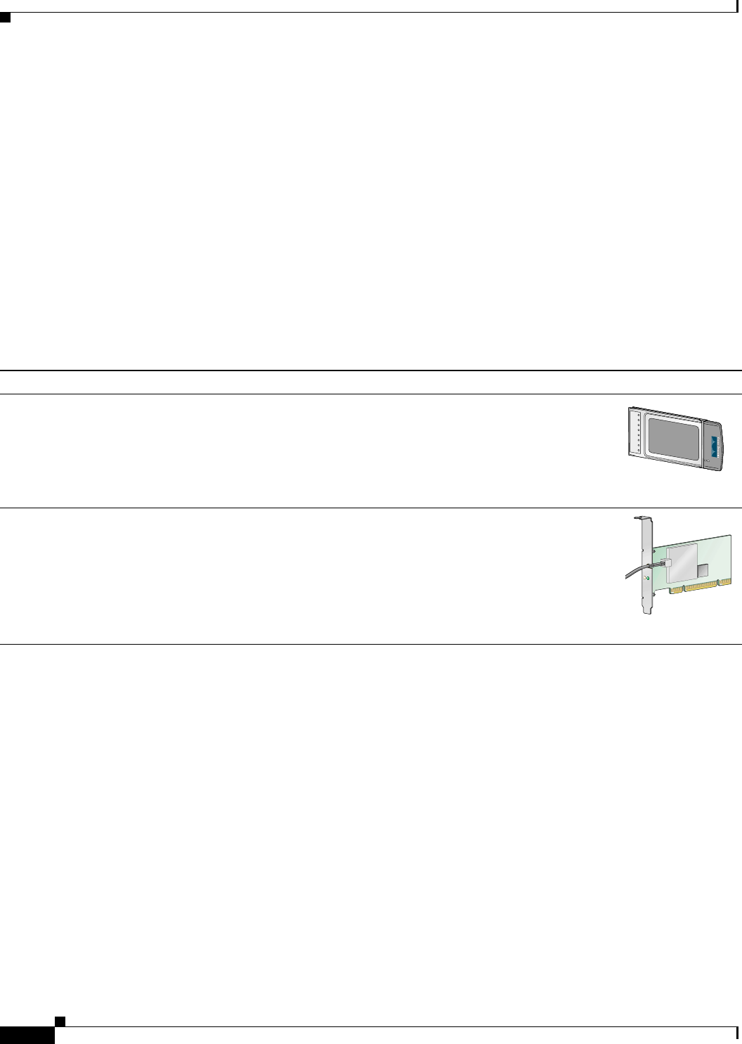
Table 1-1 Client Adapter Types
Client Adapter Model Number Description Illustration
PC-Cardbus
card AIR-CB21AG An IEEE 802.11a/b/g-compliant 2.4- and 5-GHz 54-Mbps client
adapter card radio module with a Cardbus interface that can be
inserted into any device equipped with an external 32-bit Cardbus
slot. Host devices can include laptops and notebook computers.
PCI card AIR-PI21AG An IEEE 802.11a/b/g-compliant 2.4- and 5-GHz 54-Mbps client
adapter card radio module that can be inserted into any device
equipped with an empty PCI expansion slot, such as a desktop
personal computer.
95579
95580
STATUS
ACTIVITY

BETA DRAFT - CISCO CONFIDENTIAL
1-3
Cisco Aironet 802.11a/b/g Wireless LAN Client Adapters (CB21AG and PI21AG) Installation and Configuration Guide
OL-4211-01
Chapter 1 Product Overview Hardware Components
Hardware Components
The client adapters have three major hardware components: a radio, a radio antenna, and two LEDs.
Radio
The client adapters contain a dual-band radio that is both IEEE 802.11a and 802.11b/g compliant. The
radio uses both direct-sequence spread spectrum (DSSS) technology and orthogonal frequency division
multiplexing (OFDM) technology for client applications in the 2.4-GHz Industrial Scientific Medical
(ISM) frequency band and OFDM technology in the 5-GHz Unlicensed National Information
Infrastructure (UNII) frequency bands. It can transmit data at up to 100 milliwatts (mW) in the 2.4-GHz
band or up to 40 mW in the 5-GHz band over a half-duplex radio channel operating at up to 54 Mbps.
The client adapters operate with other IEEE 802.11a or 802.11b/g-compliant client devices in ad hoc
mode or with Cisco Aironet 340, 350, 1100, and 1200 Series Access Points and other IEEE 802.11a or
802.11b/g-compliant infrastructure devices in infrastructure mode. They are approved for indoor and
outdoor use in the 2.4-GHz band and for indoor use only in the 5-GHz band except in the United States,
which allows for outdoor use on channels 52 through 64.
Radio Antenna
The type of antenna used depends on your client adapter:
•PC-Cardbus cards have an integrated, permanently attached dual-band 2.4/5-GHz diversity antenna.
The benefit of the diversity antenna system is improved coverage. The system works by allowing the
card to switch and sample between its two antenna ports in order to select the optimum port for
receiving data packets. As a result, the card has a better chance of maintaining the radio frequency
(RF) connection in areas of interference. The antenna is housed within the section of the card that
hangs out of the PC card slot when the card is installed.
• PCI cards have a 1-dBi dual-band 2.4/5-GHz antenna that is permanently attached by cable. A base
is provided with the antenna to enable it to be mounted to a wall or to sit upright on a desk or other
horizontal surface.
LEDs
The client adapters have two LEDs that glow or blink to indicate the status of the adapter or to convey
error messages. Refer to Chapter 10 for an interpretation of the LED codes.

BETA DRAFT - CISCO CONFIDENTIAL
1-4
Cisco Aironet 802.11a/b/g Wireless LAN Client Adapters (CB21AG and PI21AG) Installation and Configuration Guide OL-4211-01
Chapter 1 Product Overview
Software Components
Software Components
The client adapters have two major software components: a driver and client utilities. These components
are installed together by running a single executable Install Wizard file that is available from Cisco.com.
This file can be run on Windows 2000 or XP and can be used only with CB21AG and PI21AG client
adapters.
Note Chapter 3 provides instructions on using the Install Wizard to install these software components.
Driver
The driver provides an interface between a computer’s operating system and the client adapter, thereby
enabling the operating system and the applications it runs to communicate with the adapter. The driver
must be installed before the adapter can be used.
Client Utilities
Two client utilities are available for use with the client adapters: Aironet Desktop Utility (ADU) and
Aironet System Tray Utility (ASTU). These utilities are optional applications that interact with the client
adapter’s radio to adjust settings and display information.
ADU enables you to create configuration profiles for your client adapter and perform user-level
diagnostics. Because ADU performs a variety of functions, it is documented by function throughout this
manual.
ASTU, which is accessible from an icon in the Windows system tray, provides a small subset of the
features available through ADU. Specifically, it enables you to access status information about your
client adapter and perform basic tasks. Chapter 8 provides detailed information and instructions on using
ASTU.
Note If your computer is running Windows XP, you can configure your client adapter through the Windows
operating system instead of through ADU. Refer to Appendix E for information. However, ADU is
recommended for configuring the client adapter.
BETA DRAFT - CISCO CONFIDENTIAL
1-5
Cisco Aironet 802.11a/b/g Wireless LAN Client Adapters (CB21AG and PI21AG) Installation and Configuration Guide
OL-4211-01
Chapter 1 Product Overview Network Configurations Using Client Adapters
Network Configurations Using Client Adapters
Client adapters can be used in a variety of network configurations. In some configurations, access points
provide connections to your network or act as repeaters to increase wireless communication range. The
maximum communication range is based on how you configure your wireless network.
This section describes and illustrates the two most common network configurations:
•Ad hoc wireless local area network (LAN)
•Wireless infrastructure with workstations accessing a wired LAN
For examples of more complex network configurations involving client adapters and access points, refer
to the documentation for your access point.
Note Refer to Chapter 5 for information on setting the client adapter’s network type.
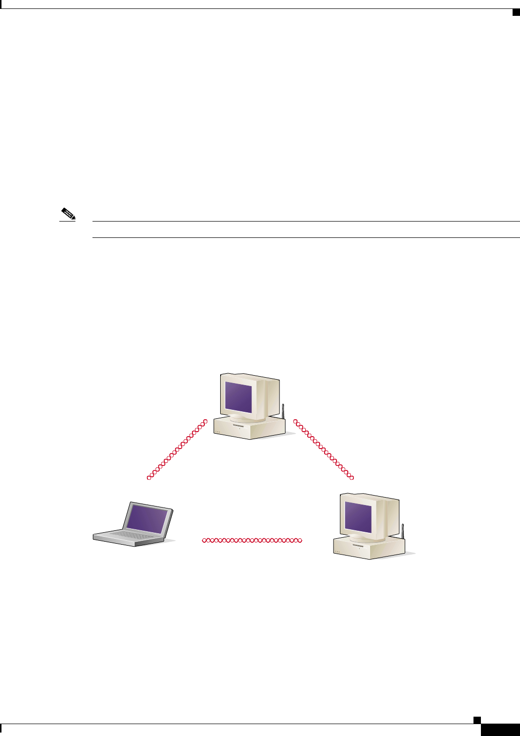
Ad Hoc Wireless LAN
An ad hoc (or peer-to-peer) wireless LAN (see Figure 1-1) is the simplest wireless LAN configuration.
In a wireless LAN using an ad hoc network configuration, all devices equipped with a client adapter can
be linked together and communicate directly with each other. The use of an infrastructure device, such
as an access point, is not required.
Figure 1-1 Ad Hoc Wireless LAN
47520
BETA DRAFT - CISCO CONFIDENTIAL
1-6
Cisco Aironet 802.11a/b/g Wireless LAN Client Adapters (CB21AG and PI21AG) Installation and Configuration Guide OL-4211-01
Chapter 1 Product Overview
Network Configurations Using Client Adapters
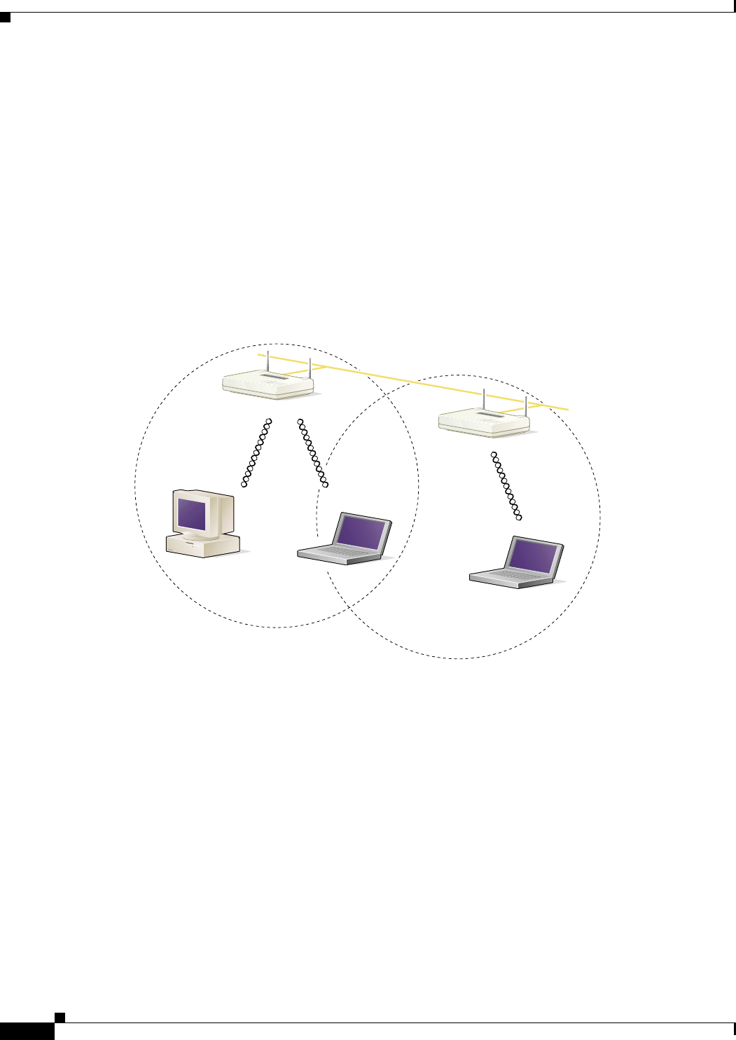
Wireless Infrastructure with Workstations Accessing a Wired LAN
A microcellular network can be created by placing two or more access points on a LAN. Figure 1-2
shows a microcellular network with workstations accessing a wired LAN through several access points.
This configuration is useful with portable or mobile stations because it allows them to be directly
connected to the wired network even while moving from one microcell domain to another. This process
is transparent, and the connection to the file server or host is maintained without disruption. The mobile
station stays connected to an access point as long as it can. However, once the transfer of data packets
needs to be retried or beacons are missed, the station automatically searches for and associates to another
access point. This process is referred to as seamless roaming.
Figure 1-2 Wireless Infrastructure with Workstations Accessing a Wired LAN
Access Point
(Root Unit)
Access Point
(Root Unit)
5835
Wired LAN

CHAPTER
BETA DRAFT - CISCO CONFIDENTIAL
2-1
Cisco Aironet 802.11a/b/g Wireless LAN Client Adapters (CB21AG and PI21AG) Installation and Configuration Guide
OL-4211-01
2
Preparing for Installation
This chapter provides information that you need to know before installing a client adapter.
The following topics are covered in this chapter:
•Safety information, page 2-2
•Unpacking the Client Adapter, page 2-3
•System Requirements, page 2-4
•Site Requirements, page 2-5

BETA DRAFT - CISCO CONFIDENTIAL
2-2
Cisco Aironet 802.11a/b/g Wireless LAN Client Adapters (CB21AG and PI21AG) Installation and Configuration Guide OL-4211-01
Chapter 2 Preparing for Installation
Safety information
Safety information
Follow the guidelines in this section to ensure proper operation and safe use of the client adapter.
FCC Safety Compliance Statement
The FCC, with its action in ET Docket 96-8, has adopted a safety standard for human exposure to RF
electromagnetic energy emitted by FCC-certified equipment. When used with approved Cisco Aironet
antennas, Cisco Aironet products meet the uncontrolled environmental limits found in OET-65 and ANSI
C95.1, 1991. Proper operation of this radio device according to the instructions in this publication will
result in user exposure substantially below the FCC recommended limits.
Safety Guidelines
•Do not touch or move the antenna while the unit is transmitting or receiving.
•Do not hold any component containing a radio such that the antenna is very close to or touching any
exposed parts of the body, especially the face or eyes, while transmitting.
•Do not operate the radio or attempt to transmit data unless the antenna is connected; otherwise, the
radio may be damaged.
•High-gain, wall-mount, or mast-mount antennas are designed to be professionally installed and
should be located at a minimum distance of 12 inches (30 cm) or more from the body of all persons.
Please contact your professional installer, VAR, or antenna manufacturer for proper installation
requirements.
•Use in specific environments:
–
The use of wireless devices in hazardous locations is limited to the constraints posed by the
safety directors of such environments.
–
The use of wireless devices on airplanes is governed by the Federal Aviation Administration
(FAA).
–
The use of wireless devices in hospitals is restricted to the limits set forth by each hospital.

BETA DRAFT - CISCO CONFIDENTIAL
2-3
Cisco Aironet 802.11a/b/g Wireless LAN Client Adapters (CB21AG and PI21AG) Installation and Configuration Guide
OL-4211-01
Chapter 2 Preparing for Installation Unpacking the Client Adapter
Warnings
Observe the following warnings when operating the client adapter:
Warning
Do not operate your wireless network device near unshielded blasting caps or in an explosive
environment unless the device has been modified to be especially qualified for such use.
Warning
In order to comply with FCC radio frequency (RF) exposure limits, dipole antennas should be located
at a minimum of 7.9 inches (20 cm) or more from the body of all persons.
Warning
This device has been tested and complies with FCC RF Exposure (SAR) limits in typical laptop
computer configurations and this device can be used in desktop or laptop computers with side
mounted PC Card slots that can provide at least 0.394 in (1 cm) separation distance from the antenna
to the body of the user or a nearby person. Thin laptop computers may need special attention to
maintain antenna spacing while operating. This device cannot be used with handheld PDAs (personal
digital assistants). Use in other configurations may not ensure compliance with FCC RF exposure
guidelines. This device and its antenna must not be co-located or operated in conjunction with any
other antenna or transmitter.
Translated versions of these safety warnings are provided in Appendix B.
Unpacking the Client Adapter
Follow these steps to unpack the client adapter:
Step 1 Open the shipping container and carefully remove the contents.
Step 2 Return all packing materials to the shipping container and save it.
Step 3 Ensure that all items listed in the “Package Contents” section below are included in the shipment. Check
each item for damage.
Note If any item is damaged or missing, notify your authorized Cisco sales representative.
Package Contents
Each client adapter is shipped with the following items:
•1-dBi antenna permanently attached by cable, antenna base, low-profile bracket, two mounting
screws, and two plastic wall anchors (PCI cards only)
•Quick Start Guide: Cisco Aironet 802.11a/b/g Wireless LAN Client Adapters (CB21AG and PI21AG)
•Cisco Aironet 802.11a/b/g Wireless Adapters (CB21AG and PI21AG) CD
•Cisco product registration card

BETA DRAFT - CISCO CONFIDENTIAL
2-4
Cisco Aironet 802.11a/b/g Wireless LAN Client Adapters (CB21AG and PI21AG) Installation and Configuration Guide OL-4211-01
Chapter 2 Preparing for Installation
System Requirements
System Requirements
In addition to the items shipped with the client adapter, you also need the following items in order to
install and use the adapter:
•One of the following computing devices running Windows 2000 or XP:
–
Laptop, notebook, or portable or handheld device equipped with a 32-bit Cardbus slot
–
Desktop personal computer equipped with an empty PCI expansion slot
Note Cisco recommends a 300-MHz processor or greater.
•Service Pack 1 for Windows XP (recommended)
•20 MB of free hard disk space (minimum)
•128 MB of RAM or greater (recommended)
•The appropriate tools for removing your computer’s cover and expansion slot dust cover and for
mounting the antenna base (for PCI cards)
•The following information from your system administrator:
–
The logical name for your workstation (also referred to as client name)
–
The protocols necessary to bind to the client adapter
–
The case-sensitive service set identifier (SSID) for your RF network
–
If your computer is not connected to a DHCP server, the IP address, subnet mask, and default
gateway address of your computer
–
The wired equivalent privacy (WEP) keys of the access points with which your client adapter
will communicate, if your wireless network uses static WEP for security
–
The username and password for your network account

BETA DRAFT - CISCO CONFIDENTIAL
2-5
Cisco Aironet 802.11a/b/g Wireless LAN Client Adapters (CB21AG and PI21AG) Installation and Configuration Guide
OL-4211-01
Chapter 2 Preparing for Installation Site Requirements
Site Requirements
This section discusses the site requirements for both infrastructure and client devices.
For Infrastructure Devices
Because of differences in component configuration, placement, and physical environment, every
network application is a unique installation. Therefore, before you install any wireless infrastructure
devices (such as access points, bridges, and base stations, which connect your client adapters to a wired
LAN), a site survey must be performed to determine the optimum placement of these devices to
maximize range, coverage, and network performance.
Note Infrastructure devices are installed and initially configured prior to client devices.
For Client Devices
Because the client adapter is a radio device, it is susceptible to RF obstructions and common sources of
interference that can reduce throughput and range. Follow these guidelines to ensure the best possible
performance:
•Install the client adapter in an area where large steel structures such as shelving units, bookcases,
and filing cabinets will not obstruct radio signals to and from the client adapter.
•Install the client adapter away from microwave ovens. Microwave ovens operate on the same
frequency as the client adapter and can cause signal interference.

BETA DRAFT - CISCO CONFIDENTIAL
2-6
Cisco Aironet 802.11a/b/g Wireless LAN Client Adapters (CB21AG and PI21AG) Installation and Configuration Guide OL-4211-01
Chapter 2 Preparing for Installation
Site Requirements

CHAPTER
BETA DRAFT - CISCO CONFIDENTIAL
3-1
Cisco Aironet 802.11a/b/g Wireless LAN Client Adapters (CB21AG and PI21AG) Installation and Configuration Guide
OL-4211-01
3
Installing the Client Adapter
This chapter provides instructions for installing the client adapter.
The following topics are covered in this chapter:
•Inserting a Client Adapter, page 3-2
•Installing the Client Adapter Software, page 3-8
•Verifying Installation, page 3-18
BETA DRAFT - CISCO CONFIDENTIAL
3-2
Cisco Aironet 802.11a/b/g Wireless LAN Client Adapters (CB21AG and PI21AG) Installation and Configuration Guide OL-4211-01
Chapter 3 Installing the Client Adapter
Inserting a Client Adapter
Inserting a Client Adapter
This section provides instructions for inserting a PC-Cardbus card or PCI card into your computer.
Caution These procedures and the physical connections they describe apply generally to conventional Cardbus
slots and PCI expansion slots. In cases of custom or nonconventional equipment, be alert to possible
differences in Cardbus slot and PCI expansion slot configurations.
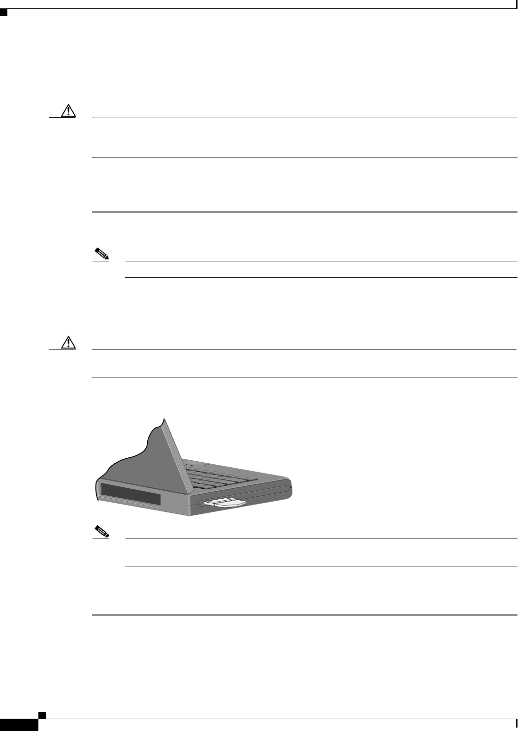
Inserting a PC-Cardbus Card
Step 1 Before you begin, examine the card. One end has a dual-row, 68-pin connector. The card is keyed so it
can be inserted only one way into the Cardbus slot.
Note The Cardbus slot is on the left or right side of the computer, depending on the model.
Step 2 Turn on your computer and let the operating system boot up completely.
Step 3 Hold the card with the Cisco logo facing up and insert it into the Cardbus slot, applying just enough
pressure to make sure it is fully seated (see Figure 3-1).
Caution Do not force the card into your computer’s Cardbus slot. Forcing it will damage both the card and the
slot. If the card does not insert easily, remove the card and reinsert it.
Figure 3-1 Inserting a PC-Cardbus Card into a Computer
Note The profiles for PC-Cardbus cards are tied to the slot in which the card is inserted. Therefore,
you must always insert your PC-Cardbus card into the same slot or create profiles for both slots.
Step 4 When the Found New Hardware Wizard screen appears, click Cancel.
Step 5 Go to the “Installing the Client Adapter Software” section on page 3-8.
BETA DRAFT - CISCO CONFIDENTIAL
3-3
Cisco Aironet 802.11a/b/g Wireless LAN Client Adapters (CB21AG and PI21AG) Installation and Configuration Guide
OL-4211-01
Chapter 3 Installing the Client Adapter Inserting a Client Adapter
Inserting a PCI Card
You must perform the following procedures in the order listed below to insert a PCI card:
•Change the bracket (if required), see below
•Insert the card, page 3-4
•Assemble the antenna, page 3-5
•Mount the antenna, page 3-6
Changing the Bracket
The PCI card is shipped with a full-profile bracket attached. If the PC into which you are inserting the
PCI card requires the card to use a low-profile bracket, follow the steps below to change brackets.
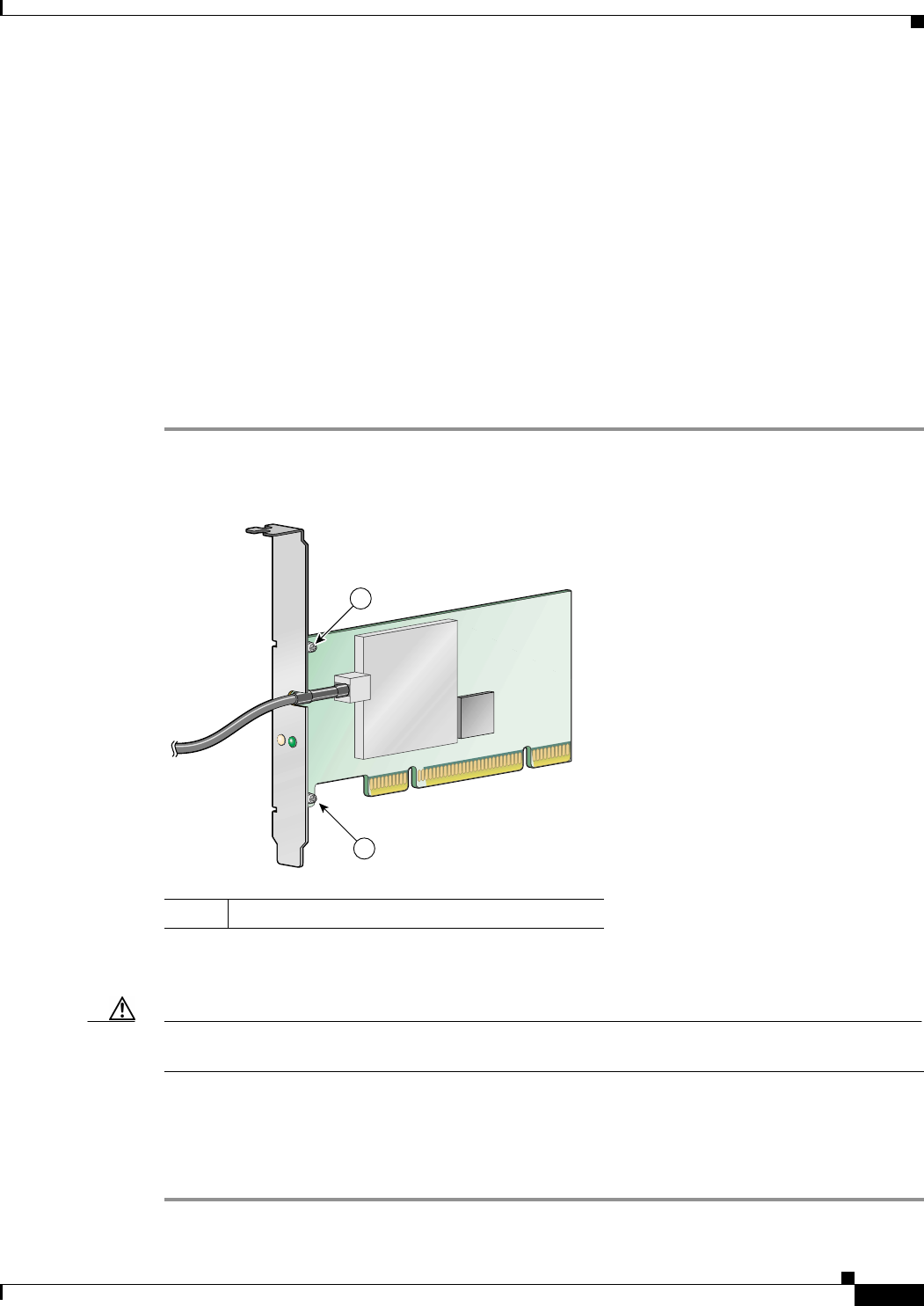
Step 1 Unscrew the two screws that attach the bracket to the card. See Figure 3-2.
Figure 3-2 Changing the PCI Card Bracket
Step 2 Slide the bracket away from the card; then tilt the bracket to free the antenna cable.
Caution Do not pull on the antenna cable or detach it from the PCI card. The antenna is meant to be permanently
attached to the card.
Step 3 Hold the low-profile bracket to the card so that the LEDs slip through their corresponding holes on the
bracket.
Step 4 Insert the screws that you removed in Step 1 into the holes on the populated side of the card near the
bracket (see Figure 3-2) and tighten.
95581
STATUS
ACTIVITY
1
1
1Bracket screws
BETA DRAFT - CISCO CONFIDENTIAL
3-4
Cisco Aironet 802.11a/b/g Wireless LAN Client Adapters (CB21AG and PI21AG) Installation and Configuration Guide OL-4211-01
Chapter 3 Installing the Client Adapter
Inserting a Client Adapter
Inserting the Card
Follow the steps below to insert a PCI card into your PC.
Step 1 Turn off the PC and all its components.
Step 2 Remove the computer cover.
Note On most Pentium PCs, PCI expansion slots are white. Refer to your PC documentation for slot
identification.
Step 3 Remove the screw from the top of the CPU back panel above an empty PCI expansion slot. This screw
holds the metal bracket on the back panel.
Caution Static electricity can damage your PCI card. Before removing the card from the anti-static packaging,
discharge static by touching a metal part of a grounded PC.
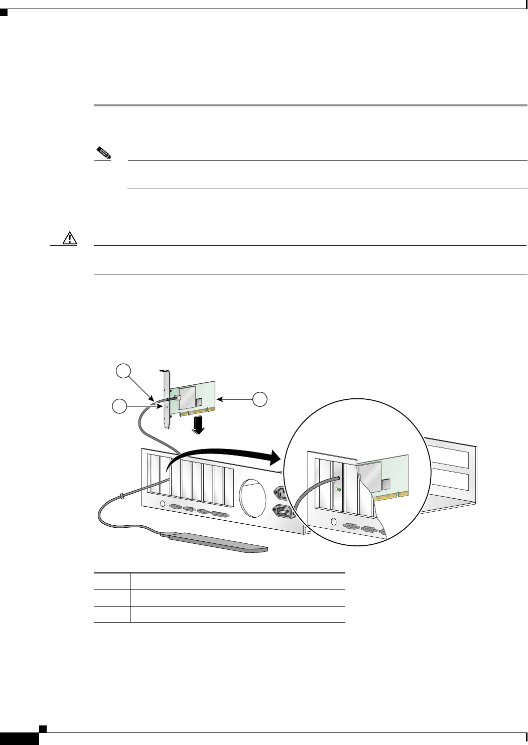
Step 4 Locate an empty PCI expansion slot inside your computer.
Step 5 Slip your card’s antenna through the opening near the empty expansion slot so that it is located outside
of the computer. See Figure 3-3.
Figure 3-3 Inserting a PCI Card into a PC
Step 6 Tilt the card to allow the LEDs to slip through the opening in the CPU back panel. See the enlarged view
in Figure 3-3.
STATUS
ACTIVITY
95582
STATUS
ACTIVITY
2
1
3
1Antenna cable
2LEDs
3Card edge connector
BETA DRAFT - CISCO CONFIDENTIAL
3-5
Cisco Aironet 802.11a/b/g Wireless LAN Client Adapters (CB21AG and PI21AG) Installation and Configuration Guide
OL-4211-01
Chapter 3 Installing the Client Adapter Inserting a Client Adapter
Step 7 Press the card into the empty slot until its connector is firmly seated.
Caution Do not force the card into the expansion slot as this could damage both the card and the slot. If the card
does not insert easily, remove it and reinsert it.
Step 8 Reinstall the screw on the CPU back panel and replace the computer cover.
Assembling the Antenna
Follow the steps below to assemble the PCI card’s antenna.
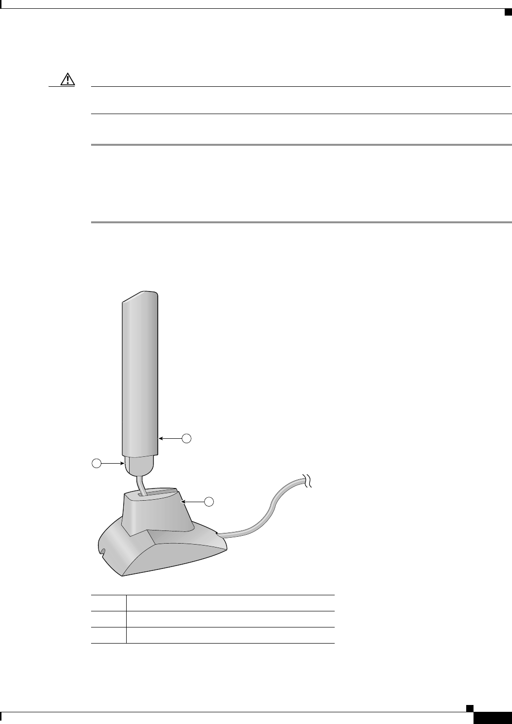
Step 1 Slide the antenna through the opening in the bottom of the antenna base.
Step 2 Position the antenna so its notches are facing the Cisco label on the front of the base. See Figure 3-4.
Figure 3-4 Inserting the Antenna into Its Base
95584
2
1
3
1Antenna
2Notch
3Antenna base
BETA DRAFT - CISCO CONFIDENTIAL
3-6
Cisco Aironet 802.11a/b/g Wireless LAN Client Adapters (CB21AG and PI21AG) Installation and Configuration Guide OL-4211-01
Chapter 3 Installing the Client Adapter
Inserting a Client Adapter
Step 3 Press the antenna cable into the receptacle on the top of the base as shown in Figure 3-4.
Step 4 Press the antenna straight down into the receptacle until it clicks into place.
Mounting the Antenna
Because the PCI card is a radio device, it is susceptible to RF obstructions and common sources of
interference that can reduce throughput and range. Follow these guidelines to ensure the best possible
performance:
•Install the PCI card’s antenna in an area where large steel structures such as shelving units,
bookcases, and filing cabinets will not obstruct radio signals being transmitted or received.
•Install the antenna away from microwave ovens and 2.4-GHz cordless phones. These products can
cause signal interference because they operate in the same frequency range as the PCI card when
used in 2.4-GHz mode.
Follow the steps below to position the PCI card’s antenna on a flat horizontal surface or to mount it to a
wall.
Step 1 Perform one of the following:
•If you want to use the antenna on a flat horizontal surface, position the antenna so it is pointing
straight up. Then go to Step 7.
•If you want to mount the antenna to a wall, go to Step 2.
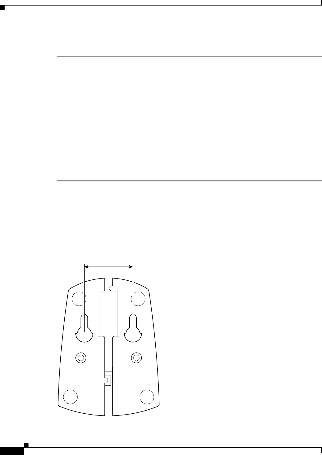
Step 2 Drill two holes in the wall that are 1.09 inches apart. Figure 3-5 shows the distance between the
mounting holes on the bottom of the antenna base.
Figure 3-5 Bottom of Antenna Base
95597
1.09 inches
BETA DRAFT - CISCO CONFIDENTIAL
3-7
Cisco Aironet 802.11a/b/g Wireless LAN Client Adapters (CB21AG and PI21AG) Installation and Configuration Guide
OL-4211-01
Chapter 3 Installing the Client Adapter Inserting a Client Adapter
Step 3 Tap the two supplied wall anchors into the holes.
Step 4 Drive the two supplied screws into the wall anchors, leaving a small gap between the screw head and the
anchor.
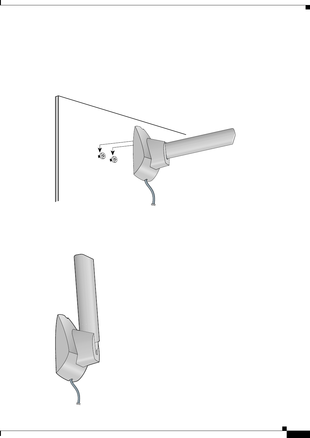
Step 5 Position the mounting holes on the bottom of the antenna base over the screws (see Figure 3-6) and pull
down to lock in place.
Figure 3-6 Mounting the Antenna
Step 6 The antenna rotates 90 degrees from its base. For optimal reception, position the antenna so it is pointing
straight up (see Figure 3-7).
Figure 3-7 Rotating the Antenna
95595
95596

BETA DRAFT - CISCO CONFIDENTIAL
3-8
Cisco Aironet 802.11a/b/g Wireless LAN Client Adapters (CB21AG and PI21AG) Installation and Configuration Guide OL-4211-01
Chapter 3 Installing the Client Adapter
Installing the Client Adapter Software
Step 7 Boot up your PC.
Step 8 When the Found New Hardware Wizard screen appears, click Cancel.
Step 9 Go to the “Installing the Client Adapter Software” section below.
Installing the Client Adapter Software
This section enables you to install Cisco Aironet CB21AG or PI21AG client adapter drivers and utilities
from a single executable file named Win-Client-802.11a-b-g-Ins-Wizard-vx.exe, where x represents the
version number. Follow the steps below to install these client adapter software components on a
computer running Windows 2000 or XP.
Caution Cisco Aironet CB21AG and PI21AG client adapter software is incompatible with other Cisco Aironet
client adapter software. Remove or disable any installed Cisco Aironet client adapters before you install
or use a CB21AG or PI21AG adapter and do not open the Aironet Client Utility (ACU). Refer to the
“Disabling a Cisco Aironet Client Adapter” section on page 10-7 for instructions on disabling a client
adapter.
Caution Do not eject your client adapter at any time during the installation process, including during the reboot.
Note This procedure is meant to be used the first time the Cisco Aironet CB21AG or PI21AG client adapter
software is installed on your computer. If this software is already installed on your computer, follow the
instructions in Chapter 9 to upgrade or uninstall the client adapter software.
Note Only one client adapter can be installed and used at a time. The software does not support the use of
multiple cards.
Step 1 Use your computer’s web browser to access the following URL:
http://www.cisco.com/public/sw-center/sw-wireless.shtml
Step 2 Select Option #2: Aironet Wireless Software Display Tables.
Note You can download software from the Software Selector tool instead of the display tables. To do
so, select Option #1: Aironet Wireless Software Selector, follow the instructions on the
screen, and go to Step 6.
Step 3 Select Cisco Aironet Wireless LAN Client Adapters.
Step 4 Under Aironet Client Adapter Installation Wizard (For Windows), select 802.11a/b/g (CB21AG,
PI21AG).
Step 5 Select the Install Wizard file with the greatest version number.
Step 6 Read and accept the terms and conditions of the Software License Agreement.
BETA DRAFT - CISCO CONFIDENTIAL
3-9
Cisco Aironet 802.11a/b/g Wireless LAN Client Adapters (CB21AG and PI21AG) Installation and Configuration Guide
OL-4211-01
Chapter 3 Installing the Client Adapter Installing the Client Adapter Software
Step 7 Select the file again to download it.
Step 8 Save the file to your computer’s hard drive.
Step 9 Use Windows Explorer to find the file.
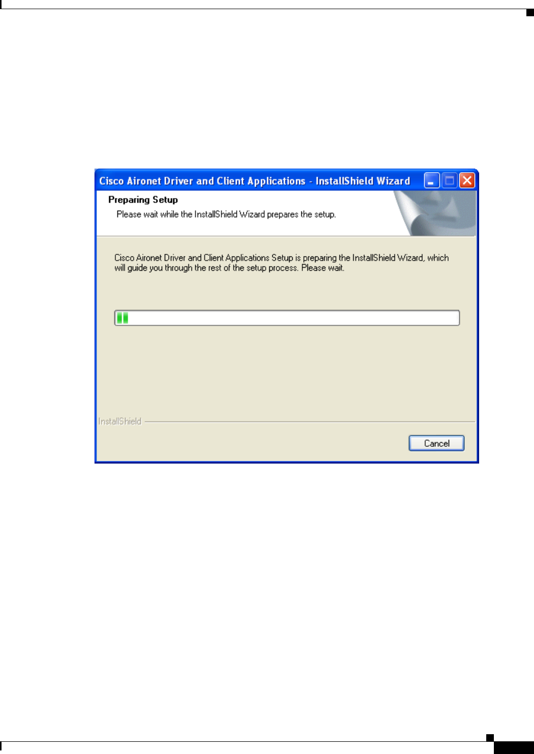
Step 10 Double-click the file. The “Starting InstallShield Wizard” message appears followed by the Preparing
Setup screen (see Figure 3-8) and the Cisco Aironet Installation Program screen (see Figure 3-9).
Figure 3-8 Preparing Setup Screen
BETA DRAFT - CISCO CONFIDENTIAL
3-10
Cisco Aironet 802.11a/b/g Wireless LAN Client Adapters (CB21AG and PI21AG) Installation and Configuration Guide OL-4211-01
Chapter 3 Installing the Client Adapter
Installing the Client Adapter Software
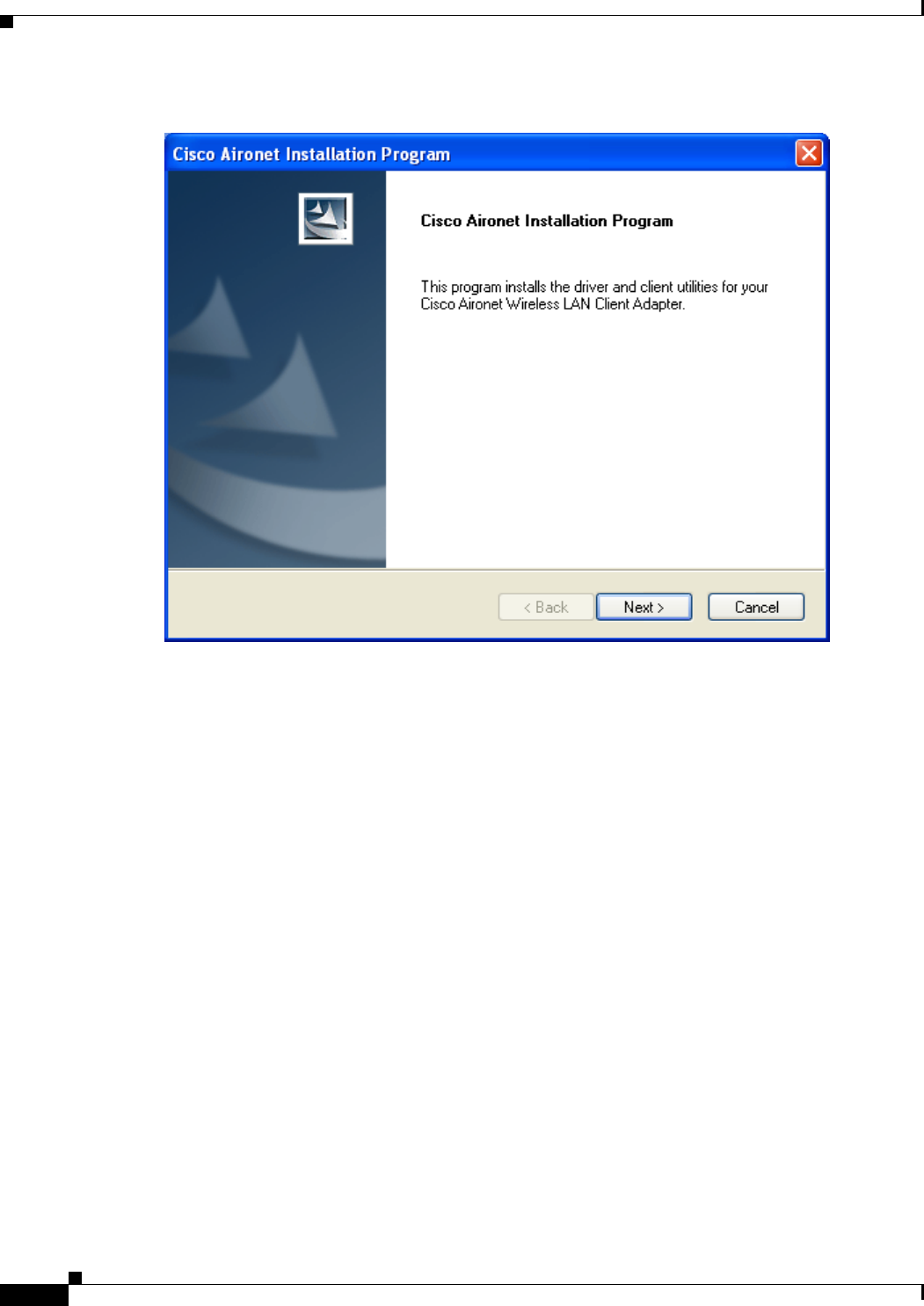
Figure 3-9 Cisco Aironet Installation Program Screen
Step 11 Click Next. The Setup Type screen appears (see Figure 3-10).
BETA DRAFT - CISCO CONFIDENTIAL
3-11
Cisco Aironet 802.11a/b/g Wireless LAN Client Adapters (CB21AG and PI21AG) Installation and Configuration Guide
OL-4211-01
Chapter 3 Installing the Client Adapter Installing the Client Adapter Software
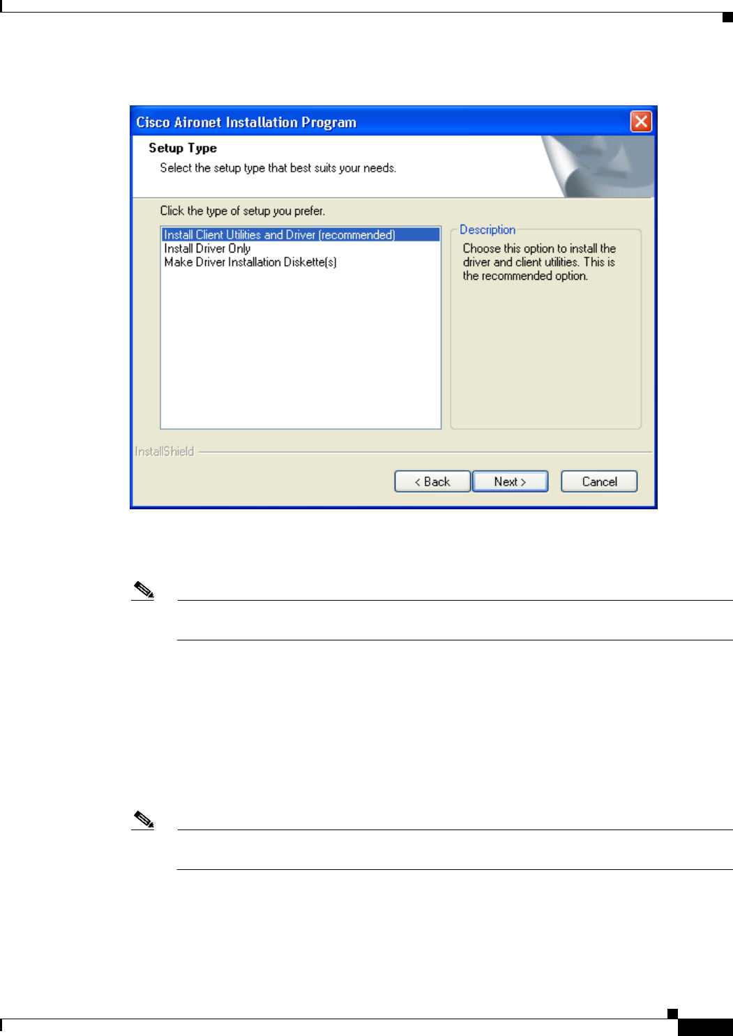
Figure 3-10 Setup Type Screen
Step 12 Select one of the following options:
Note To ensure compatibility among software components, Cisco recommends that you install the
client utilities and driver.
•Install Client Utilities and Driver (recommended)—Installs the client adapter driver and client
utilities.
•Install Driver Only—Installs only the client adapter driver. If you select this option, go to Step 24.
•Make Driver Installation Diskette(s)—Enables you to create driver installation diskettes.
Step 13 Click Next.
Step 14 If a message appears indicating that you are required to restart your computer at the end of the
installation process, click Yes.
Note If you click No, you are asked to confirm your decision. If you proceed, the installation process
terminates.
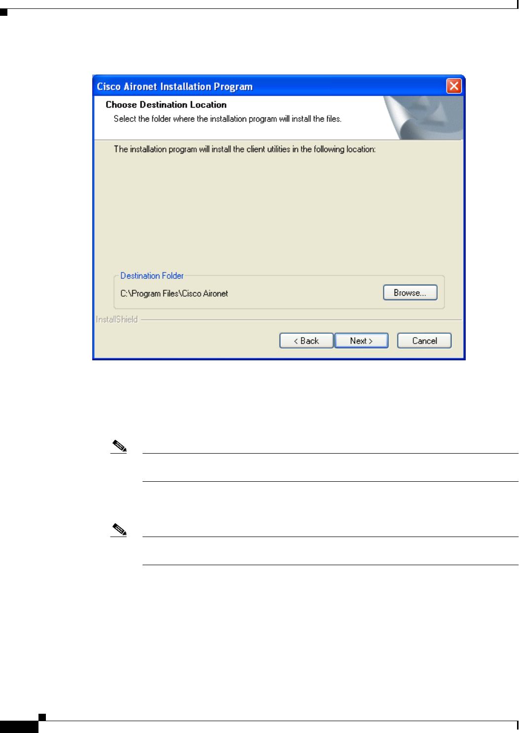
The Choose Destination Location screen appears (see Figure 3-11).
BETA DRAFT - CISCO CONFIDENTIAL
3-12
Cisco Aironet 802.11a/b/g Wireless LAN Client Adapters (CB21AG and PI21AG) Installation and Configuration Guide OL-4211-01
Chapter 3 Installing the Client Adapter
Installing the Client Adapter Software
Figure 3-11 Choose Destination Location Screen
Step 15 Perform one of the following:
•If you selected the first option in Step 12, click Next to install the client utility files in the
C:\Program Files\Cisco Aironet directory.
Note If you want to install the client utilities in a different directory, click Browse, select a
different directory, click OK, and click Next.
•If you selected the Make Driver Installation Diskette(s) option in Step 12, insert a floppy disk into
your computer and click Next to copy the driver to the diskette. Go to Step 24.
Note If you want to copy the driver to a different drive or directory, click Browse, select a new
location, click OK, and click Next.
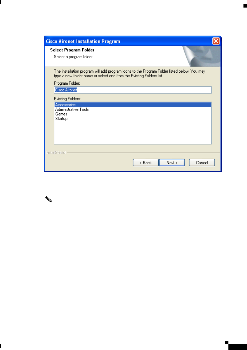
Step 16 The Select Program Folder screen appears (see Figure 3-12).
BETA DRAFT - CISCO CONFIDENTIAL
3-13
Cisco Aironet 802.11a/b/g Wireless LAN Client Adapters (CB21AG and PI21AG) Installation and Configuration Guide
OL-4211-01
Chapter 3 Installing the Client Adapter Installing the Client Adapter Software
Figure 3-12 Select Program Folder Screen
Step 17 Click Next to add program icons to the Cisco Aironet program folder.
Note If you want to specify a different program folder, select a folder from the Existing Folders list
or type a new folder name in the Program Folder field and click Next.
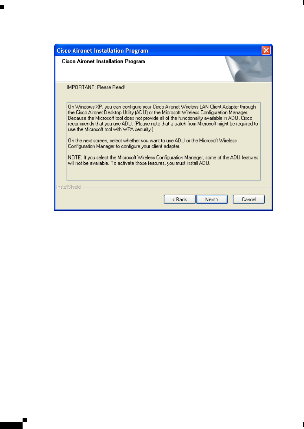
Step 18 If your computer is running Windows 2000, go to Step 24. If your computer is running Windows XP, the
IMPORTANT: Please Read! screen appears (see Figure 3-13).
BETA DRAFT - CISCO CONFIDENTIAL
3-14
Cisco Aironet 802.11a/b/g Wireless LAN Client Adapters (CB21AG and PI21AG) Installation and Configuration Guide OL-4211-01
Chapter 3 Installing the Client Adapter
Installing the Client Adapter Software
Figure 3-13 IMPORTANT: Please Read! Screen
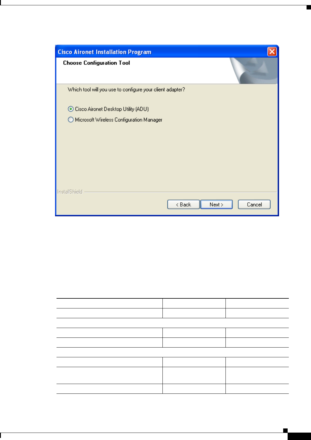
Step 19 Read the information displayed and click Next. The Choose Configuration Tool screen appears (see
Figure 3-14).
BETA DRAFT - CISCO CONFIDENTIAL
3-15
Cisco Aironet 802.11a/b/g Wireless LAN Client Adapters (CB21AG and PI21AG) Installation and Configuration Guide
OL-4211-01
Chapter 3 Installing the Client Adapter Installing the Client Adapter Software
Figure 3-14 Choose Configuration Tool Screen
Step 20 Select one of the following options:
•Cisco Aironet Desktop Utility (ADU)—Enables you to configure your client adapter using ADU.
•Microsoft Wireless Configuration Manager—Enables you to configure your client adapter using
the Microsoft Wireless Configuration Manager in Windows XP.
To help you with your decision, Table 3-1 compares the Windows XP and ADU client adapter features.
Table 3-1 Comparison of Windows XP and ADU Client Adapter Features
Feature Windows XP ADU
Configuration parameters Limited Extensive
Capabilities
Create profiles No Yes
Turn radio on or off No Yes
Security
Static WEP Yes Yes
LEAP authentication with dynamic
WEP No Yes
EAP-TLS or PEAP authentication Yes Yes
BETA DRAFT - CISCO CONFIDENTIAL
3-16
Cisco Aironet 802.11a/b/g Wireless LAN Client Adapters (CB21AG and PI21AG) Installation and Configuration Guide OL-4211-01
Chapter 3 Installing the Client Adapter
Installing the Client Adapter Software
Note If you select Cisco Aironet Desktop Utility (ADU), the Microsoft Wireless Configuration
Manager is disabled. If you ever manually enable it, you are prompted to disable it whenever
ADU is activated.
Step 21 Click Next.
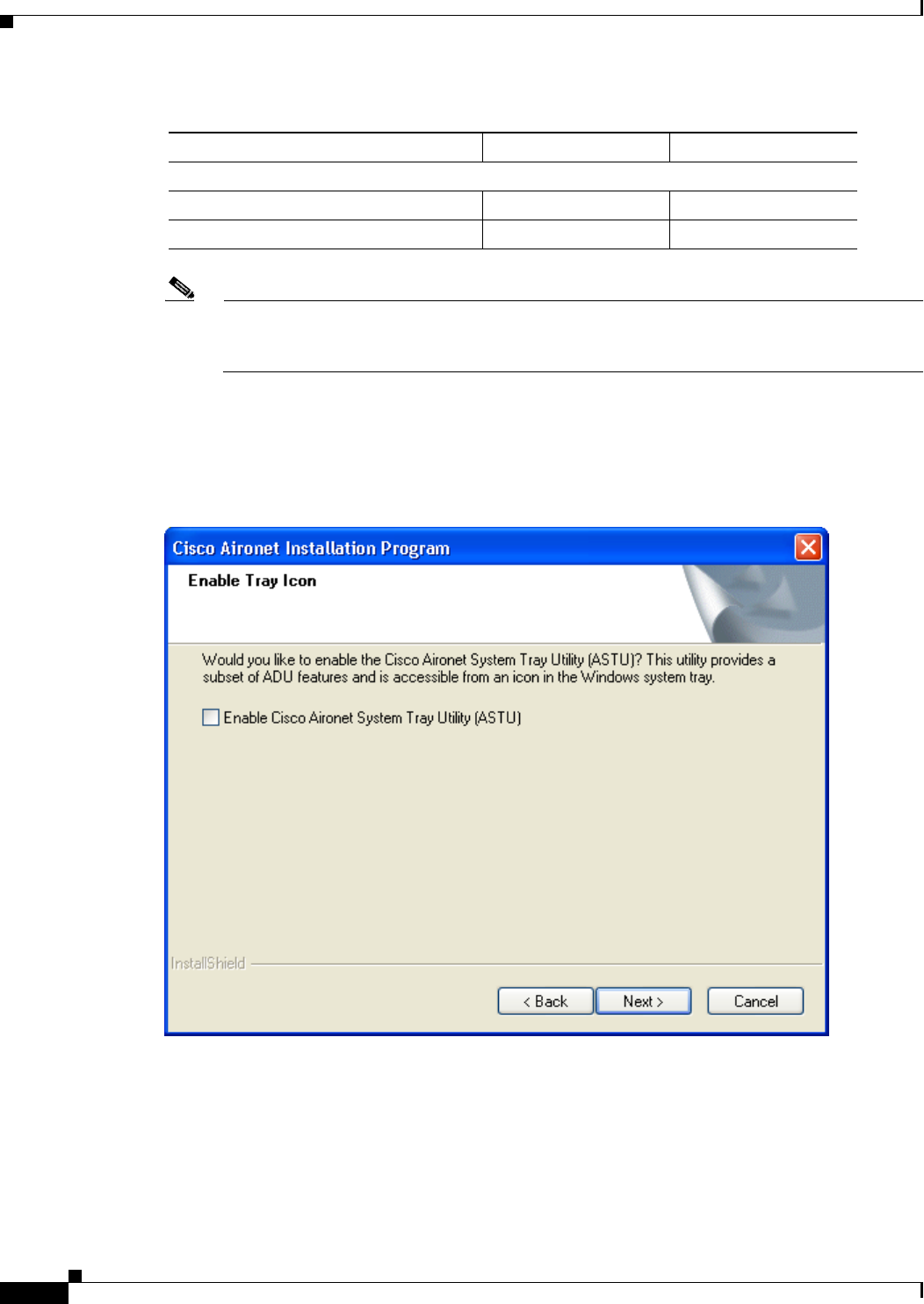
Step 22 If you selected Cisco Aironet Desktop Utility (ADU) in Step 20, go to Step 24. If you selected Microsoft
Wireless Configuration Manager, the Enable Tray Icon screen appears (see Figure 3-15).
Figure 3-15 Enable Tray Icon Screen
Step 23 Check the Enable Cisco Aironet System Tray Utility (ASTU) check box if you want to be able to use
ASTU even though you have chosen to configure your client adapter through Windows instead of ADU.
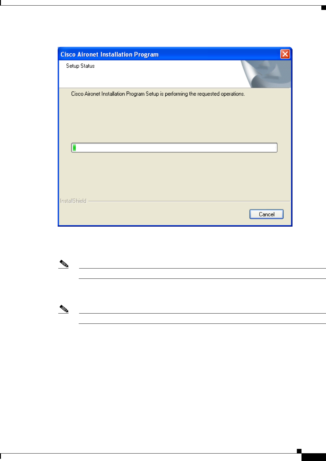
Step 24 When prompted to insert your client adapter, click OK. The Setup Status screen appears (see
Figure 3-16).
Diagnostics
Status screen Limited Extensive
Statistics screen (transmit & receive) No Yes
Table 3-1 Comparison of Windows XP and ADU Client Adapter Features (continued)
Feature Windows XP ADU
BETA DRAFT - CISCO CONFIDENTIAL
3-17
Cisco Aironet 802.11a/b/g Wireless LAN Client Adapters (CB21AG and PI21AG) Installation and Configuration Guide
OL-4211-01
Chapter 3 Installing the Client Adapter Installing the Client Adapter Software
Figure 3-16 Setup Status Screen
The installation process begins, and you are notified as each software component is installed.
Note This process may take several minutes.
Step 25 When a message appears indicating that your computer needs to be rebooted, click OK and allow your
computer to restart.
Note This process may take several minutes.
Step 26 After your computer reboots, the Windows Found New Hardware Wizard appears. Click Next, allow the
wizard to install the software for the client adapter, and click Finish.

BETA DRAFT - CISCO CONFIDENTIAL
3-18
Cisco Aironet 802.11a/b/g Wireless LAN Client Adapters (CB21AG and PI21AG) Installation and Configuration Guide OL-4211-01
Chapter 3 Installing the Client Adapter
Verifying Installation
Step 27 If your computer is not connected to a DHCP server and you plan to use TCP/IP, follow the steps below
for your operating system.
•Windows 2000—Double-click My Computer, Control Panel, and Network and Dial-up
Connections. Right-click Local Area Connection x (where x represents the number of the
connection). Click Properties. In the Components Checked Are Used by This Connection field,
select Internet Protocol (TCP/IP) and click Properties. Click Use the following IP address and
enter the IP address, subnet mask, and default gateway address of your computer (which can be
obtained from your system administrator). Click OK twice.
•Windows XP—Double-click My Computer, Control Panel, and Network Connections.
Right-click Wireless Network Connection x (where x represents the number of the connection).
Click Properties. In the This Connection Uses the Following Items field, select Internet Protocol
(TCP/IP) and click Properties. Select Use the following IP address and enter the IP address,
subnet mask, and default gateway address of your computer (which can be obtained from your
system administrator). Click OK twice.
Step 28 If you are prompted to restart your computer, click Yes.
Step 29 Go to the “Verifying Installation” section below to determine if the installation was successful.
Verifying Installation
To verify that you have properly installed the client adapter software, check the client adapter’s LEDs.
If the installation was successful, the client adapter’s green LED blinks.
Note If your installation was unsuccessful or you experienced problems during or after installation, refer to
Chapter 10 for troubleshooting information.
Now that your client adapter is properly installed, it is ready to be configured.
•If you are planning to configure your client adapter through ADU, go to Chapter 4 to create
configuration profiles.
•If you are planning to configure your client adapter through Windows XP’s Wireless Configuration
Manager, go to Appendix E.

CHAPTER
BETA DRAFT - CISCO CONFIDENTIAL
4-1
Cisco Aironet 802.11a/b/g Wireless LAN Client Adapters (CB21AG and PI21AG) Installation and Configuration Guide
OL-4211-01
4
Using the Profile Manager
This chapter explains how to use ADU’s profile manager feature to create and manage profiles for your
client adapter.
The following topics are covered in this chapter:
•Overview of Profile Manager, page 4-2
•Opening Profile Manager, page 4-2
•Creating a New Profile, page 4-4
•Including a Profile in Auto Profile Selection, page 4-7
•Selecting the Active Profile, page 4-8
•Modifying a Profile, page 4-9
•Importing and Exporting Profiles, page 4-10
BETA DRAFT - CISCO CONFIDENTIAL
4-2
Cisco Aironet 802.11a/b/g Wireless LAN Client Adapters (CB21AG and PI21AG) Installation and Configuration Guide OL-4211-01
Chapter 4 Using the Profile Manager
Overview of Profile Manager
Overview of Profile Manager
ADU’s profile manager feature allows you to create and manage up to 16 profiles (or saved
configurations) for your client adapter. These profiles enable you to use your client adapter in different
locations, each of which requires different configuration settings. For example, you may want to set up
profiles for using your client adapter at the office, at home, and in public areas such as airports. Once
the profiles are created, you can easily switch between them without having to reconfigure your client
adapter each time you enter a new location.
Profiles are stored in the registry and are lost if you uninstall the client adapter’s software. To prevent
your profiles from becoming lost, Cisco recommends that you back up your profiles using the profile
manager’s import/export feature. See the “Importing and Exporting Profiles” section on page 4-10 for
details.
Opening Profile Manager
Step 1 To open ADU’s profile manager, double-click the Aironet Desktop Utility icon on your desktop.
Step 2 Click the Profile Management tab. The Cisco Aironet Desktop Utility (Profile Management) screen
appears (see Figure 4-1).
Figure 4-1 Cisco Aironet Desktop Utility (Profile Management) Screen
Note The profile manager feature provides you with a default profile that is configured to use default values.
This profile is named Default and appears in the profiles list on the Cisco Aironet Desktop Utility
(Profile Management) screen. You can use this profile as is or modify it by following the instructions in
the “Modifying a Profile” section on page 4-9.

BETA DRAFT - CISCO CONFIDENTIAL
4-3
Cisco Aironet 802.11a/b/g Wireless LAN Client Adapters (CB21AG and PI21AG) Installation and Configuration Guide
OL-4211-01
Chapter 4 Using the Profile Manager Opening Profile Manager
Table 4-1 provides a description of the status fields on the Cisco Aironet Desktop Utility (Profile
Management) screen.
Profile manager allows you to perform the following tasks related to the management of profiles:
•Create a new profile, page 4-4
•Include a profile in auto profile selection, page 4-7
•Select the active profile, page 4-8
•Edit a profile, page 4-9
•Delete a profile, page 4-9
•Import a profile, page 4-10
•Export a profile, page 4-11
Follow the instructions on the page indicated for the task you want to perform.
Note If your system administrator used an administrative tool to deactivate certain parameters, these
parameters are grayed out and cannot be selected.
Table 4-1 Description of Status Fields on Profile Management Screen
Field Description
Network Type The type of network that is configured for the selected profile.
Value: Infrastructure or Ad Hoc
Note Refer to the Network Type parameter in Table 5-3 for instructions on
setting the network type.
Security Mode The type of security that is configured for the selected profile.
Value: Disabled, Pre-Shared Keys (Static WEP), Pre-Shared Keys, LEAP,
EAP-TLS, PEAP (EAP-GTC), or PEAP (EAP-MSCHAP V2)
Network Name 1
(SSID1) The service set identifier (SSID) is the wireless network that is configured for
the selected profile.
Note Refer to the SSID1 parameter in Table 5-2 for instructions on setting
SSID1.
Network Name 2
(SSID2) An optional SSID that is configured for the selected profile. It identifies a
second distinct network and enables the client adapter to roam to that network
without having to be reconfigured.
Note Refer to the SSID2 parameter in Table 5-2 for instructions on setting
SSID2.
Network Name 3
(SSID3) An optional SSID that is configured for the selected profile. It identifies a
third distinct network and enables the client adapter to roam to that network
without having to be reconfigured.
Note Refer to the SSID3 parameter in Table 5-2 for instructions on setting
SSID3.
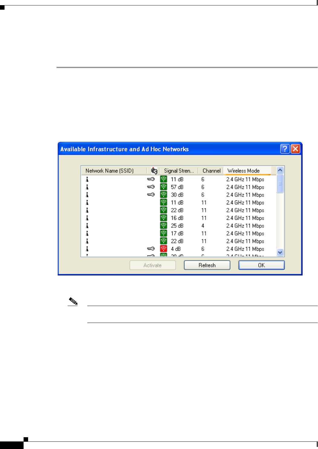
BETA DRAFT - CISCO CONFIDENTIAL
4-4
Cisco Aironet 802.11a/b/g Wireless LAN Client Adapters (CB21AG and PI21AG) Installation and Configuration Guide OL-4211-01
Chapter 4 Using the Profile Manager
Creating a New Profile
Creating a New Profile
Follow the steps below to create a new profile.
Step 1 Perform one of the following:
•If you want to create a new profile from scratch, click New on the Cisco Aironet Desktop Utility
(Profile Management) screen. Then go to Step 4.
•If you want to find an available network and create a profile based on it, click Scan on the Cisco
Aironet Desktop Utility (Profile Management) screen. The Available Infrastructure and Ad Hoc
Networks screen appears (see Figure 4-2).
Figure 4-2 Available Infrastructure and Ad Hoc Networks Screen
This screen displays a list of all available networks.
Note The Allow Broadcast SSID to Associate option on the access point must be enabled for the
SSID to appear in the list of available networks.
Table 4-2 provides a description of the fields on the Available Infrastructure and Ad Hoc Networks
screen.
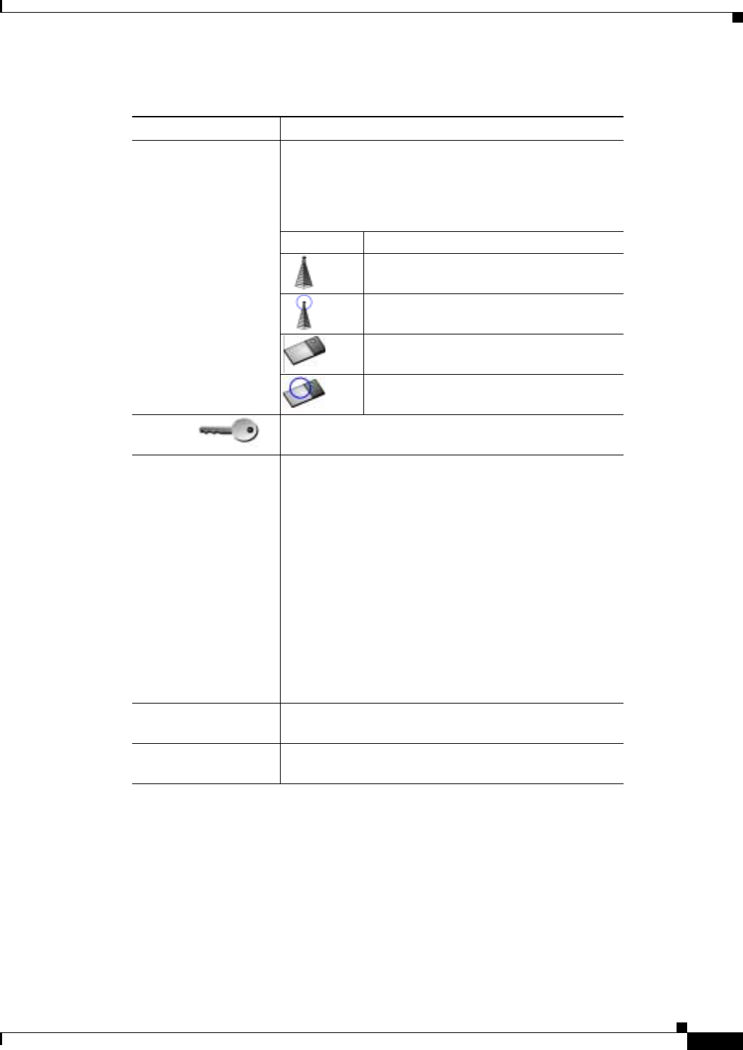
BETA DRAFT - CISCO CONFIDENTIAL
4-5
Cisco Aironet 802.11a/b/g Wireless LAN Client Adapters (CB21AG and PI21AG) Installation and Configuration Guide
OL-4211-01
Chapter 4 Using the Profile Manager Creating a New Profile
The information on the Available Infrastructure and Ad Hoc Networks screen is updated at the rate
specified by the Refresh Interval parameter on the Display Settings screen. See the “Setting Parameters
that Affect ADU Diagnostic Tools” section on page 7-2 for more information. You can also click the
Refresh button to update the list of available networks.
Step 2 Scroll down to see the full list of available networks.
Step 3 Click on the SSID of the network to which you want your client adapter to associate and click Activate.
Step 4 When the Profile Management (General) screen appears (see Figure 4-3), enter a name for your new
profile (such as Office, Home, etc.) in the Profile Name field.
Table 4-2 Description of Available Infrastructure and Ad Hoc Networks Screen
Field Description
Network Name (SSID) The service set identifier (SSID) indicates the name of an
available wireless network. The icons to the left of the
SSIDs provide information on network type and link
status.
Icon Description
An available infrastructure network.
The infrastructure network to which your
client adapter is currently associated.
An available ad hoc network.
The ad hoc network to which your client
adapter is currently associated.
Key icon SSIDs that are designated with a key icon are being
advertised as secure networks.
Signal Strength The signal strength for all received packets. The higher
the value, the stronger the signal.
Note The color of this parameter’s icon provides a
visual interpretation of signal strength:
Excellent or Good (green), Fair (yellow), Poor
(red).
Note The signal strength is displayed either in decibels
(dB) or as a percentage (%), depending on the
value selected for the Signal Strength Display
Units parameter on the Display Settings screen.
See the “Setting Parameters that Affect ADU
Diagnostic Tools” section on page 7-2 for more
information.
Channel The channel that the access point is using for
communications.
Wireless Mode The frequency and rate at which the access point is
configured to transmit and receive packets.
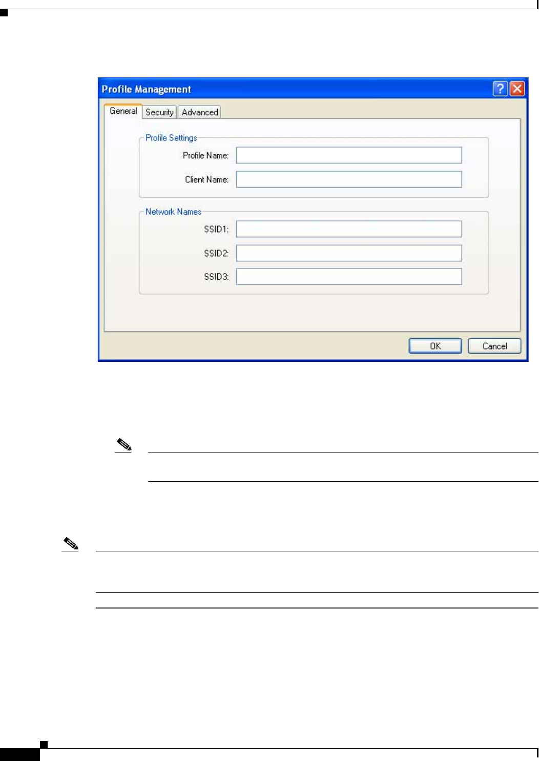
BETA DRAFT - CISCO CONFIDENTIAL
4-6
Cisco Aironet 802.11a/b/g Wireless LAN Client Adapters (CB21AG and PI21AG) Installation and Configuration Guide OL-4211-01
Chapter 4 Using the Profile Manager
Creating a New Profile
Figure 4-3 Profile Management (General) Screen
Step 5 Perform one of the following:
•If you want this profile to use the default values, click OK. The profile is added to the profiles list
on the Cisco Aironet Desktop Utility (Profile Management) screen.
Note If you are creating a profile after scanning for an available network, the SSID of the network
appears in the SSID1 field.
•If you want to change any of the configuration parameter settings, follow the instructions in
Chapter 5. The profile is added to the profiles list on the Cisco Aironet Desktop Utility (Profile
Management) screen.
Note The profiles for PC-Cardbus cards are tied to the slot in which the card is inserted. Therefore, you must
always insert your PC-Cardbus card into the same slot, create profiles for both slots, or export the
profiles from one slot and import them for the other slot.
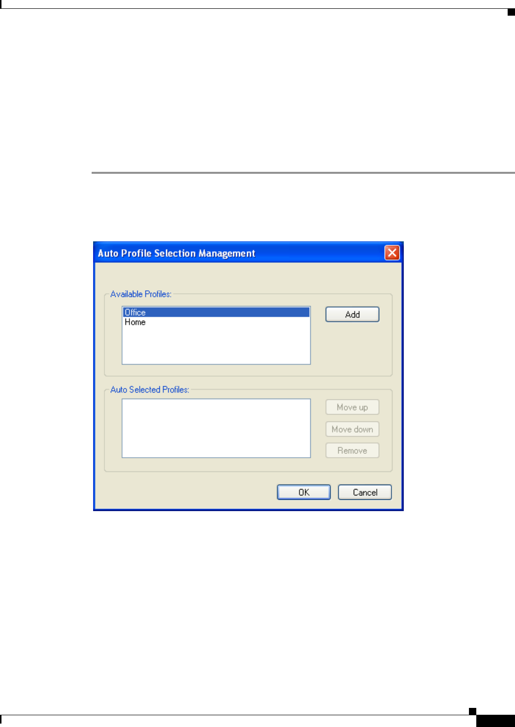
BETA DRAFT - CISCO CONFIDENTIAL
4-7
Cisco Aironet 802.11a/b/g Wireless LAN Client Adapters (CB21AG and PI21AG) Installation and Configuration Guide
OL-4211-01
Chapter 4 Using the Profile Manager Including a Profile in Auto Profile Selection
Including a Profile in Auto Profile Selection
After you have created profiles for your client adapter, you can choose to include them in the profile
manager’s auto profile selection feature. Then when auto profile selection is enabled, the client adapter
automatically selects a profile from the list of profiles that were included in auto profile selection and
uses it to establish a connection to the network.
Follow the steps below to include any of your profiles in auto profile selection and to establish the order
in which the profiles will be selected for use.
Step 1 Open ADU and click the Profile Management tab.
Step 2 Click Order Profiles. The Auto Profile Selection Management screen appears (see Figure 4-4).
Figure 4-4 Auto Profile Selection Management Screen
Step 3 All the profiles that you created are listed in the Available Profiles box. Highlight each one that you want
to include in auto profile selection and click the Add button. The profiles appear in the Auto Selected
Profiles box.
The following rules apply to auto profile selection:
•You must include at least two profiles in the Auto Selected Profiles box.
•The profiles must specify an SSID; otherwise, they do not appear in the Available Profiles
box.
•Profiles cannot specify multiple SSIDs; otherwise, they do not appear in the Available
Profiles box.

BETA DRAFT - CISCO CONFIDENTIAL
4-8
Cisco Aironet 802.11a/b/g Wireless LAN Client Adapters (CB21AG and PI21AG) Installation and Configuration Guide OL-4211-01
Chapter 4 Using the Profile Manager
Selecting the Active Profile
•Each profile that is included in auto profile selection must have a unique SSID. For example,
if Profile A and Profile B both have “ABCD” as their SSID, only Profile A or Profile B (whichever
one was created first) appears in the Available Profiles box and can be included in auto profile
selection.
Note If you ever want to remove a profile from auto profile selection, highlight the profile in the Auto
Selected Profiles box and click Remove. The profile is removed from the Auto Selected Profiles
box.
Step 4 The first profile in the Auto Selected Profiles box has the highest priority while the last profile has the
lowest priority. To change the order (and priority) of your auto-selectable profiles, highlight the profile
that you want to move and click Move up or Move down to move the profile up or down, respectively.
Step 5 Click OK.
When auto profile selection is enabled (see the “Selecting the Active Profile” section below for
instructions), the client adapter scans for an available network. The profile with the highest priority and
the same SSID as one of the found networks is the one that is used to connect to the network. If the
connection fails, the client adapter tries the next highest priority profile that matches the SSID and so on.
Selecting the Active Profile
Follow the steps below to specify the profile that the client adapter is to use.
Note You can use ASTU instead of ADU’s Profile Manager to select the active profile. Refer to Chapter 8 for
instructions.
Step 1 Open ADU and click the Profile Management tab. The Cisco Aironet Desktop Utility (Profile
Management) screen appears (see Figure 4-1).
Step 2 Perform one of the following:
•Select one profile for the client adapter to use by clicking on that profile in the profiles list.
If the client adapter cannot associate to an access point or loses association while using the selected
profile, the adapter does not attempt to associate using another profile. To associate, you must select
a different profile or activate auto profile selection.
•Enable auto profile selection by checking the Auto Select Profiles check box.
This option causes the client adapter’s driver to automatically select a profile from the list of profiles
that were set up to be included in auto profile selection.
If the client adapter loses association for more than 10 seconds (or for more than the time specified
by the LEAP authentication timeout value on the LEAP Settings screen if LEAP is enabled), the
driver switches automatically to another profile that is included in auto profile selection. The adapter
will not switch profiles as long as it remains associated or reassociates within 10 seconds (or within
the time specified by the LEAP authentication timeout value). To force the client adapter to associate
to a different access point, you must uncheck the Auto Select Profiles check box and select a new
profile from the profiles list.

BETA DRAFT - CISCO CONFIDENTIAL
4-9
Cisco Aironet 802.11a/b/g Wireless LAN Client Adapters (CB21AG and PI21AG) Installation and Configuration Guide
OL-4211-01
Chapter 4 Using the Profile Manager Modifying a Profile
Note This option is available only if two or more profiles are included in auto profile selection.
Note Login scripts are not reliable if you use auto profile selection with LEAP. If you LEAP
authenticate and achieve full network connectivity before or at the same time as you log into
the computer, the login scripts will run. However, if you LEAP authenticate and achieve full
network connectivity after you log into the computer, the login scripts will not run.
•Click Scan. The Available Infrastructure and Ad Hoc Networks screen appears (see Figure 4-2).
Double-click the SSID of a network that is used by one of your profiles and click OK. Go to Step 4.
Step 3 Click Activate to save your selection.
Step 4 The client adapter starts using a profile based on the option selected above. The active profile is
designated by the following icon in the profiles list:
Modifying a Profile
This section provides instructions for modifying an existing profile. Follow the steps in the
corresponding section below to edit or delete a profile.
Editing a Profile
Step 1 Open ADU and click the Profile Management tab. The Cisco Aironet Desktop Utility (Profile
Management) screen appears (see Figure 4-1).
Step 2 In the profiles list, highlight the profile that you want to edit.
Step 3 Click Modify.
Step 4 Follow the instructions in Chapter 5 to change any of the configuration parameters for this profile.
Deleting a Profile
Step 1 Open ADU and click the Profile Management tab. The Cisco Aironet Desktop Utility (Profile
Management) screen appears (see Figure 4-1).
Step 2 In the profiles list, highlight the profile that you want to delete.
Step 3 Click Remove. The profile is deleted.
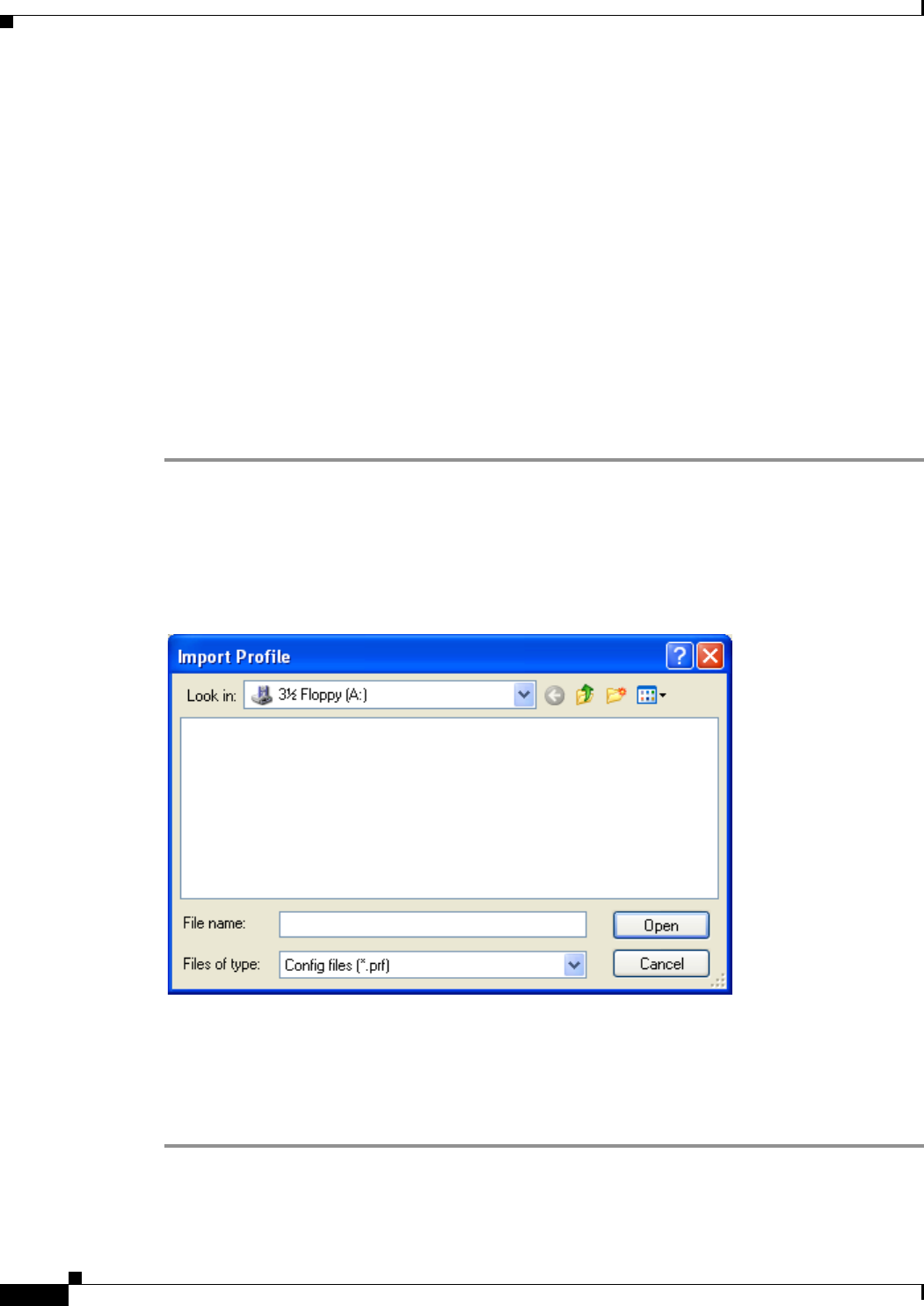
BETA DRAFT - CISCO CONFIDENTIAL
4-10
Cisco Aironet 802.11a/b/g Wireless LAN Client Adapters (CB21AG and PI21AG) Installation and Configuration Guide OL-4211-01
Chapter 4 Using the Profile Manager
Importing and Exporting Profiles
Importing and Exporting Profiles
This section provides instructions for importing and exporting profiles. You may want to use the
import/export feature for the following reasons:
•To back up profiles before uninstalling client adapter software
•To export profiles for a PC-Cardbus card in one Cardbus slot and export them for use with a second
Cardbus slot
•To set up your computer with a profile from another computer
•To export one of your profiles and use it to set up additional computers
Follow the steps in the corresponding section below to import or export profiles.
Importing a Profile
Step 1 If the profile that you want to import is on a floppy disk, insert the disk into your computer’s floppy drive.
Step 2 Open ADU and click the Profile Management tab. The Cisco Aironet Desktop Utility (Profile
Management) screen appears (see Figure 4-1).
Step 3 Click Import. The Import Profile screen appears (see Figure 4-5).
Figure 4-5 Import Profile Screen
Step 4 In the Look in drop-down box, find the directory where the profile is located.
Step 5 Select the profile that you want to import so it appears in the File name box at the bottom of the screen.
Step 6 Click Open. The imported profile appears in the profiles list on the Cisco Aironet Desktop Utility
(Profile Management) screen.
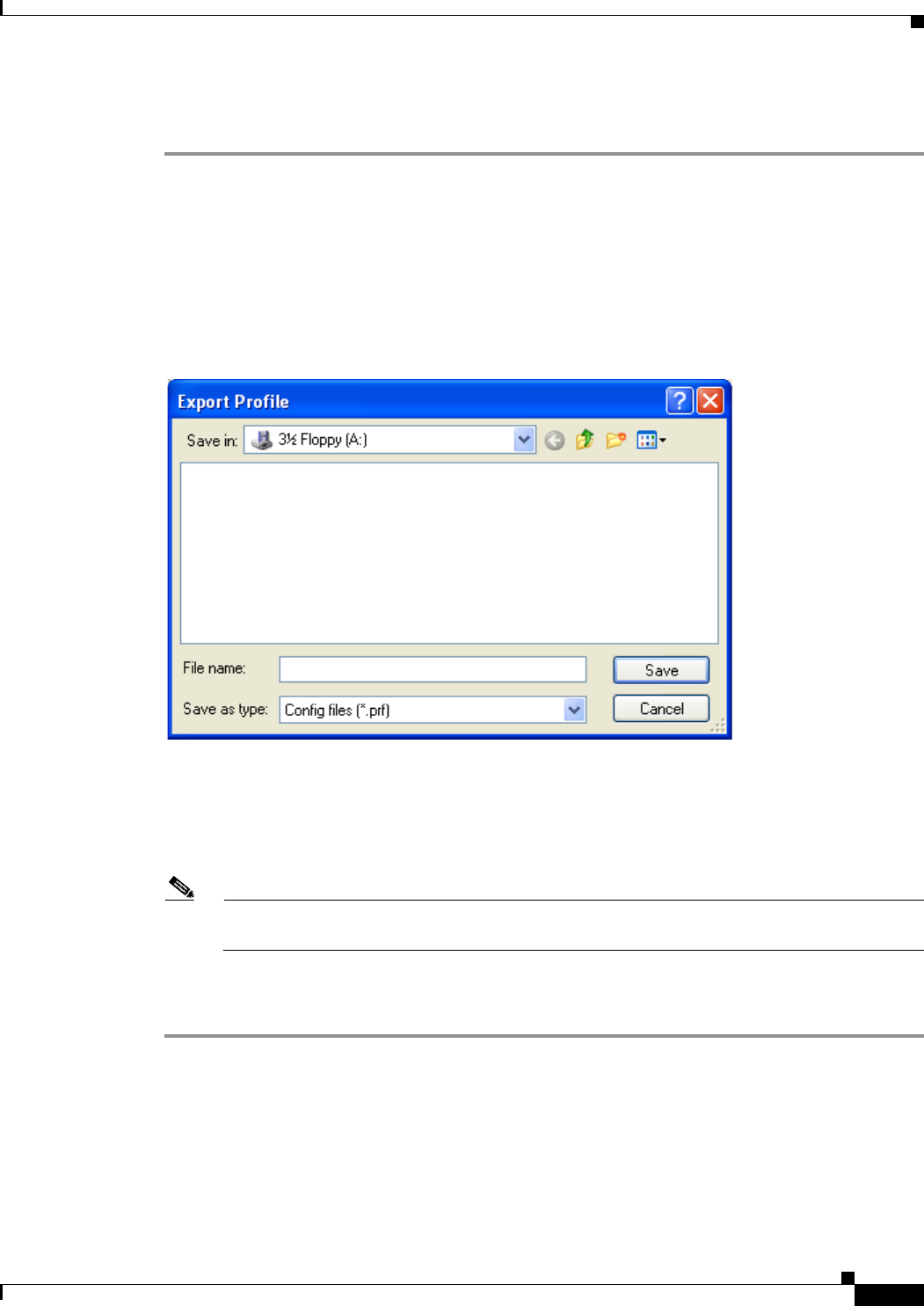
BETA DRAFT - CISCO CONFIDENTIAL
4-11
Cisco Aironet 802.11a/b/g Wireless LAN Client Adapters (CB21AG and PI21AG) Installation and Configuration Guide
OL-4211-01
Chapter 4 Using the Profile Manager Importing and Exporting Profiles
Exporting a Profile
Step 1 Insert a blank floppy disk into your computer’s floppy drive, if you wish to export a profile to a floppy
disk.
Step 2 Open ADU and click the Profile Management tab. The Cisco Aironet Desktop Utility (Profile
Management) screen appears (see Figure 4-1).
Step 3 In the profiles list, select the profile that you want to export.
Step 4 Click Export. The Export Profile screen appears (see Figure 4-6).
Figure 4-6 Export Profile Screen
The profile name appears in the File name box.
Step 5 Select a directory (for example, your computer’s floppy disk drive or a location on the network) from
the Save in drop-down box.
Note The default location is the Profiles folder in the directory where ADU is installed (for example,
C:\Program Files\Cisco Aironet\Profiles).
Step 6 Click Save. The profile is exported to the specified location.
Step 7 Follow the instructions in the “Importing a Profile” section to import the profile on another computer.

BETA DRAFT - CISCO CONFIDENTIAL
4-12
Cisco Aironet 802.11a/b/g Wireless LAN Client Adapters (CB21AG and PI21AG) Installation and Configuration Guide OL-4211-01
Chapter 4 Using the Profile Manager
Importing and Exporting Profiles

CHAPTER
BETA DRAFT - CISCO CONFIDENTIAL
5-1
Cisco Aironet 802.11a/b/g Wireless LAN Client Adapters (CB21AG and PI21AG) Installation and Configuration Guide
OL-4211-01
5
Configuring the Client Adapter
This chapter explains how to change the configuration parameters for a specific profile. The following
topics are covered in this chapter:
•Overview, page 5-2
•Setting General Parameters, page 5-3
•Setting Advanced Parameters, page 5-5
•Setting Security Parameters, page 5-10

BETA DRAFT - CISCO CONFIDENTIAL
5-2
Cisco Aironet 802.11a/b/g Wireless LAN Client Adapters (CB21AG and PI21AG) Installation and Configuration Guide OL-4211-01
Chapter 5 Configuring the Client Adapter
Overview
Overview
When you choose to create a new profile or modify an existing profile on the Cisco Aironet Desktop
Utility (Profile Management) screen, the Profile Management screens appear. These screens enable you
to set the configuration parameters for that profile.
Note If you do not change any of the configuration parameters, the default values are used.
Note If you are planning to set parameters on more than one of the Profile Management screens, wait until
you are finished with all of the screens before clicking OK. When you click OK, you are returned to the
Cisco Aironet Desktop Utility (Profile Management) screen.
Each of the Profile Management screens (listed below) contains parameters that affect a specific aspect
of the client adapter:
•General—Prepares the client adapter for use in a wireless network
•Advanced—Controls how the client adapter operates within an infrastructure or ad hoc network
•Security—Controls how a client adapter associates to an access point, authenticates to the wireless
network, and encrypts and decrypts data
Table 5-1 enables you to quickly locate instructions for setting each Profile Management screen’s
parameters.
Table 5-1 Locating Configuration Instructions
Parameter Category Page Number
General page 5-3
Advanced page 5-5
Security page 5-10
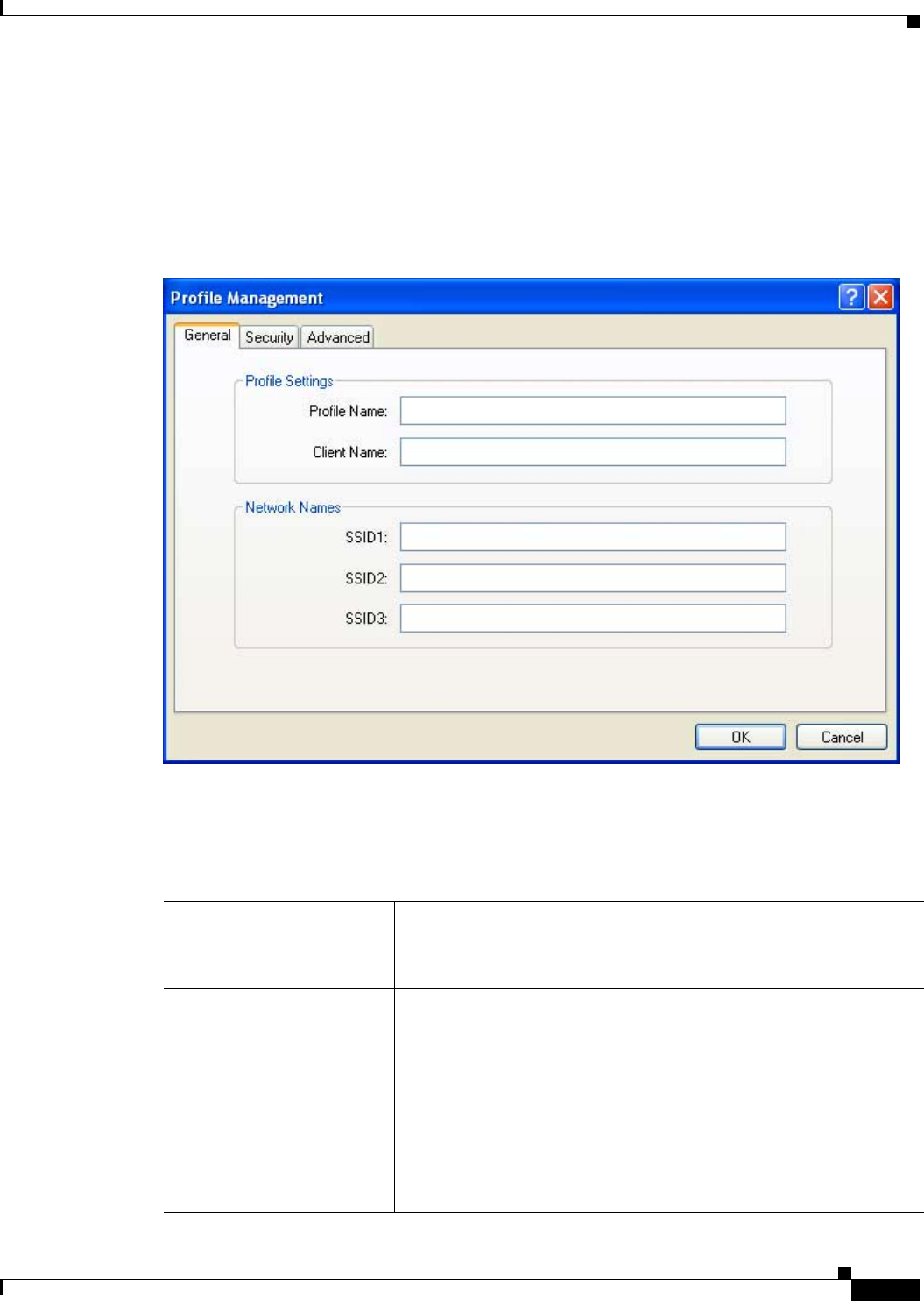
BETA DRAFT - CISCO CONFIDENTIAL
5-3
Cisco Aironet 802.11a/b/g Wireless LAN Client Adapters (CB21AG and PI21AG) Installation and Configuration Guide
OL-4211-01
Chapter 5 Configuring the Client Adapter Setting General Parameters
Setting General Parameters
The Profile Management (General) screen (see Figure 5-1) enables you to set parameters that prepare
the client adapter for use in a wireless network. This screen appears after you click New or Modify on
the Cisco Aironet Desktop Utility (Profile Management) screen.
Figure 5-1 Profile Management (General) Screen
Table 5-2 lists and describes the client adapter’s general parameters. Follow the instructions in the table
to change any parameters.
Table 5-2 Profile Management General Parameters
Parameter Description
Profile Name The name assigned to the configuration profile.
Range: You can key in up to 32 ASCII characters
Client Name A logical name for your workstation. It allows an administrator to
determine which devices are connected to the access point without
having to memorize every MAC address. This name is included in the
access point’s list of connected devices. The client name is filled in
automatically but can be changed.
Range: You can key in up to 16 ASCII characters
Default: The name of your computer
Note Each computer on the network should have a unique client
name.

BETA DRAFT - CISCO CONFIDENTIAL
5-4
Cisco Aironet 802.11a/b/g Wireless LAN Client Adapters (CB21AG and PI21AG) Installation and Configuration Guide OL-4211-01
Chapter 5 Configuring the Client Adapter
Setting General Parameters
Go to the next section to set additional parameters or click OK to save your changes and return to the
Cisco Aironet Desktop Utility (Profile Management) screen.
SSID1 The service set identifier (SSID) identifies the specific wireless
network that you want the client adapter to access.
Range: You can key in up to 32 ASCII characters (case sensitive)
Default: A blank field
Note If you leave this parameter blank, your client adapter can
associate to any access point on the network that is configured
to allow broadcast SSIDs. If the access point with which the
client adapter is to communicate is not configured to allow
broadcast SSIDs, the value of this parameter must match the
SSID of the access point. Otherwise, the client adapter is unable
to access the network.
SSID2 An optional SSID that identifies a second distinct network and enables
the client adapter to roam to that network without having to be
reconfigured.
Range: You can key in up to 32 ASCII characters (case sensitive)
Default: A blank field
Note If a profile specifies more than one SSID, it cannot be included
in auto profile selection.
Note This field is unavailable for any profiles that are included in
auto profile selection or configured for use in an ad hoc
network.
SSID3 An optional SSID that identifies a third distinct network and enables the
client adapter to roam to that network without having to be
reconfigured.
Range: You can key in up to 32 ASCII characters (case sensitive)
Default: A blank field
Note If a profile specifies more than one SSID, it cannot be included
in auto profile selection.
Note This field is unavailable for any profiles that are included in
auto profile selection or configured for use in an ad hoc
network.
Table 5-2 Profile Management General Parameters (continued)
Parameter Description
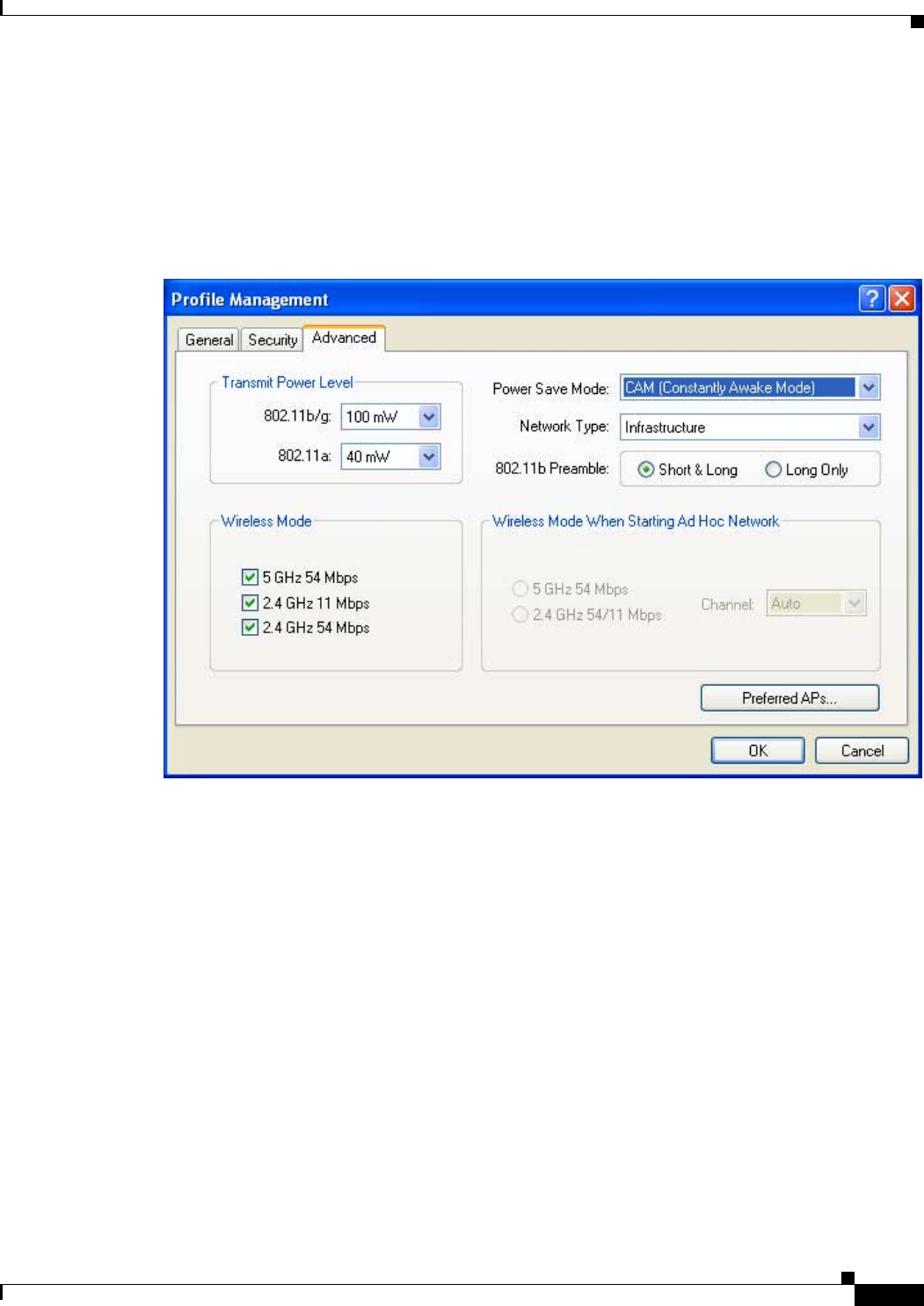
BETA DRAFT - CISCO CONFIDENTIAL
5-5
Cisco Aironet 802.11a/b/g Wireless LAN Client Adapters (CB21AG and PI21AG) Installation and Configuration Guide
OL-4211-01
Chapter 5 Configuring the Client Adapter Setting Advanced Parameters
Setting Advanced Parameters
The Profile Management (Advanced) screen (see Figure 5-2) enables you to set parameters that control
how the client adapter operates within an infrastructure or ad hoc network. To access this screen, select
the Advanced tab from any Profile Management screen.
Figure 5-2 Profile Management (Advanced) Screen
Table 5-3 lists and describes the client adapter’s advanced parameters. Follow the instructions in the
table to change any parameters.

BETA DRAFT - CISCO CONFIDENTIAL
5-6
Cisco Aironet 802.11a/b/g Wireless LAN Client Adapters (CB21AG and PI21AG) Installation and Configuration Guide OL-4211-01
Chapter 5 Configuring the Client Adapter
Setting Advanced Parameters
Table 5-3 Profile Management Advanced Parameters
Parameter Description
Transmit Power Level Defines the power level at which your client adapter transmits. This
value must not be higher than that allowed by your country’s regulatory
agency (FCC in the U.S., DOC in Canada, ETSI in Europe, MKK in
Japan, etc.).
Options:Dependent on the radio band used and the power table
programmed into the client adapter; see the table below
Default: The maximum power level programmed into the client adapter
and allowed by your country’s regulatory agency
Radio Band Transmit Power Level
802.11b/g 10, 20, 32, 50, 63, or 100 mW
802.11a 10, 13, 20, 25, or 40 mW
Note Reducing the transmit power level conserves battery power but
decreases radio range.

BETA DRAFT - CISCO CONFIDENTIAL
5-7
Cisco Aironet 802.11a/b/g Wireless LAN Client Adapters (CB21AG and PI21AG) Installation and Configuration Guide
OL-4211-01
Chapter 5 Configuring the Client Adapter Setting Advanced Parameters
Power Save Mode Sets your client adapter to its optimum power consumption setting.
Options:CAM (Constantly Awake Mode), Fast PSP (Power Save
Mode), or Max PSP (Max Power Saving)
Default: CAM (Constantly Awake Mode)
Power Save Mode Description
CAM (Constantly Awake
Mode) Keeps the client adapter powered up
continuously so there is little lag in
message response time.
Consumes the most power but offers the
highest throughput. Is recommended for
desktop computers and devices that use
AC power.
Fast PSP (Power Save
Mode) Switches between PSP mode and CAM
mode, depending on network traffic. This
mode switches to CAM when retrieving a
large number of packets and switches back
to PSP after the packets have been
retrieved.
Is recommended when power consumption
is a concern but you need greater
throughput than that allowed by Max PSP.
Max PSP (Max Power
Saving) Causes the access point to buffer incoming
messages for the client adapter, which
wakes up periodically and polls the access
point to see if any buffered messages are
waiting for it. The adapter can request
each message and then go back to sleep.
Conserves the most power but offers the
lowest throughput. Is recommended for
devices for which power consumption is
the ultimate concern (such as small
battery-powered devices).
Note If you select Ad Hoc for Network Type, CAM mode is used
automatically.
Table 5-3 Profile Management Advanced Parameters (continued)
Parameter Description

BETA DRAFT - CISCO CONFIDENTIAL
5-8
Cisco Aironet 802.11a/b/g Wireless LAN Client Adapters (CB21AG and PI21AG) Installation and Configuration Guide OL-4211-01
Chapter 5 Configuring the Client Adapter
Setting Advanced Parameters
Network Type Specifies the type of network in which your client adapter is installed.
Options:Infrastructure or Ad Hoc
Default: Infrastructure
Network Type Description
Ad Hoc Often referred to as peer to peer. Indicates
that your wireless network consists of a
few wireless devices that are not
connected to a wired Ethernet network
through an access point. For example, an
ad hoc network could be set up between
computers in a conference room so users
can share information in a meeting.
Infrastructure Indicates that your wireless network is
connected to a wired Ethernet network
through an access point.
802.11b Preamble Determines whether your client adapter will use both short and long
radio headers or only long radio headers. The adapter can use short
radio headers only if the access point is also configured to support them
and is using them. If any clients associated to an access point are using
long headers, then all clients in that cell must also use long headers,
even if both this client and the access point have short radio headers
enabled.
Short radio headers improve throughput performance; long radio
headers ensure compatibility with clients and access points that do not
support short radio headers.
Options:Short & Long or Long Only
Default: Short & Long
Wireless Mode Specifies the frequency and rate at which your client adapter will
transmit or receive packets to or from access points.
Options:5 GHz 54 Mbps, 2.4 GHz 11 Mbps, and 2.4 GHz 54 Mbps
Default: All options selected
Note When more than one option is selected, the client adapter
attempts to use the wireless modes in this order:
2.4 GHz 54 Mbps, 5 GHz 54 Mbps, 2.4 GHz 11 Mbps.
Note If you select 2.4 GHz 54 Mbps, the client attempts to associate
to access points containing an 802.11b or 802.11g radio. If you
select 2.4 GHz 11 Mbps, the client attempts to associate only to
access points containing an 802.11b radio.
Note Your client adapter’s wireless mode must match that of the
access points with which it is to communicate. Otherwise, your
client adapter may not be able to associate to them.
Table 5-3 Profile Management Advanced Parameters (continued)
Parameter Description

BETA DRAFT - CISCO CONFIDENTIAL
5-9
Cisco Aironet 802.11a/b/g Wireless LAN Client Adapters (CB21AG and PI21AG) Installation and Configuration Guide
OL-4211-01
Chapter 5 Configuring the Client Adapter Setting Advanced Parameters
If your client adapter is being configured for use in an infrastructure network and you want to specify
up to four access points to which the client adapter should attempt to associate, click Preferred APs.
The Preferred Access Points screen appears (see Figure 5-3).
Wireless Mode When Starting
Ad Hoc Network Specifies the frequency and rate at which your client adapter will
transmit or receive packets to or from other clients (in ad hoc mode).
Options:5 GHz 54 Mbps or 2.4 GHz 54/11 Mbps
Default: 5 GHz 54 Mbps
Note Your client adapter’s wireless mode must match that of the
other clients with which it is to communicate. Otherwise, your
client adapter may not be able to associate to them.
Note The client scans the band(s) specified by the Wireless Mode
parameter before creating a new ad hoc cell based on the band
specified by the Wireless Mode When Starting Ad Hoc
Network parameter.
Channel Specifies the channel that your client adapter will use for
communications in a 2.4-GHz ad hoc network. The available channels
conform to the IEEE 802.11 Standard for your regulatory domain.
The channel of the client adapter must be set to match the channel used
by the other clients in the wireless network. If the client adapter does
not find any other ad hoc clients, this parameter specifies the channel
with which the adapter will start its cell.
Range: Dependent on regulatory domain
Example: 1 to 11 (2412 to 2462 MHz) in North America
Default: Auto (the client automatically determines the channel on
which to start communications)
Note This parameter is available only when 2.4 GHz 54/11 Mbps is
selected for the Wireless Mode When Starting Ad Hoc Network
parameter. When 5 GHz 54 Mbps is selected, the Channel
parameter is set to Auto automatically.
Note Refer to Appendix D for a list of channel identifiers, channel
center frequencies, and regulatory domains for each channel.
Table 5-3 Profile Management Advanced Parameters (continued)
Parameter Description
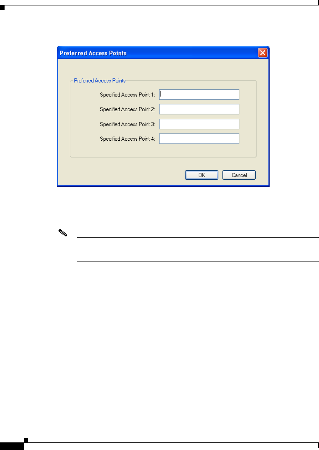
BETA DRAFT - CISCO CONFIDENTIAL
5-10
Cisco Aironet 802.11a/b/g Wireless LAN Client Adapters (CB21AG and PI21AG) Installation and Configuration Guide OL-4211-01
Chapter 5 Configuring the Client Adapter
Setting Security Parameters
Figure 5-3 Preferred Access Points Screen
Leave the Specified Access Point fields blank or enter the MAC addresses of up to four preferred access
points to which the client adapter can associate; then click OK. If the specified access points are not
found or the client adapter roams out of range, the adapter may associate to another access point.
Note This parameter should be used only for access points that are in repeater mode. For normal
operation, leave these fields blank because specifying an access point slows down the roaming
process.
Go to the next section to set additional parameters or click OK to save your changes and return to the
Cisco Aironet Desktop Utility (Profile Management) screen.
Setting Security Parameters
The Profile Management (Security) screen (see Figure 5-4) enables you to set parameters that control
how the client adapter associates to an access point, authenticates to the wireless network, and encrypts
and decrypts data. To access this screen, select the Security tab from any Profile Management screen.
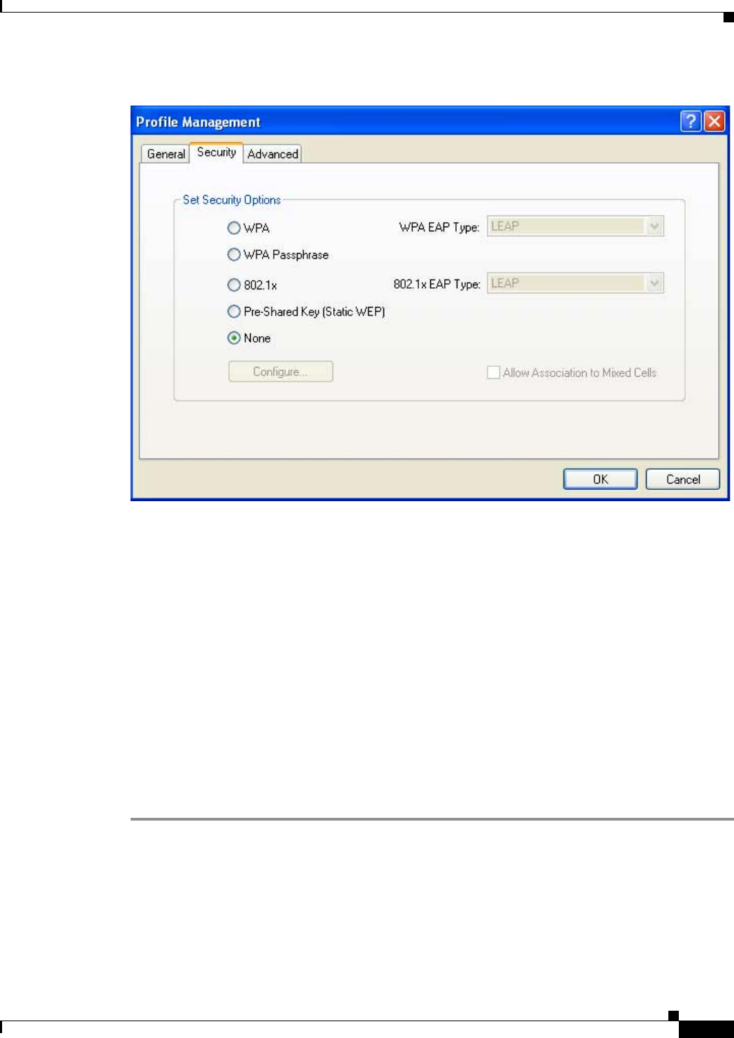
BETA DRAFT - CISCO CONFIDENTIAL
5-11
Cisco Aironet 802.11a/b/g Wireless LAN Client Adapters (CB21AG and PI21AG) Installation and Configuration Guide
OL-4211-01
Chapter 5 Configuring the Client Adapter Setting Security Parameters
Figure 5-4 Profile Management (Security) Screen
This screen is different from the other Profile Management screens in that it includes many security
features, each of which involves a number of steps. In addition, the security features themselves are
complex and need to be understood before they are implemented. Therefore, this section provides an
overview of the security features as well as procedures for using them.
However, before you determine the appropriate security settings for your client adapter, you must decide
how to set the Allow Association to Mixed Cells parameter, which appears at the bottom of the Profile
Management (Security) screen and is not associated to any of the security features. See the “Setting the
Allow Association to Mixed Cells Parameter” section below.
Setting the Allow Association to Mixed Cells Parameter
The Allow Association to Mixed Cells parameter indicates whether the client adapter can associate to
an access point that allows both WEP and non-WEP associations. Follow the steps below to set this
parameter.
Step 1 Perform one of the following:
•Check the Allow Association to Mixed Cells check box if the access point to which the client
adapter is to associate has WEP set to Optional and WEP is enabled on the client adapter. Otherwise,
the client is unable to establish a connection with the access point.
•Uncheck the Allow Association to Mixed Cells check box if the access point to which the client
adapter is to associate does not have WEP set to Optional. This is the default setting.

BETA DRAFT - CISCO CONFIDENTIAL
5-12
Cisco Aironet 802.11a/b/g Wireless LAN Client Adapters (CB21AG and PI21AG) Installation and Configuration Guide OL-4211-01
Chapter 5 Configuring the Client Adapter
Setting Security Parameters
Note For security reasons, Cisco recommends that WEP-enabled and WEP-disabled clients not be
allowed in the same cell because broadcast packets are sent unencrypted, even to clients running
WEP.
Step 2 Perform one of the following:
•If you do not want to change any other parameters on the Profile Management (Security) screen,
click OK to save your changes and return to the Cisco Aironet Desktop Utility (Profile
Management) screen.
•If you want to change some of the other parameters on the Profile Management (Security) screen,
go to the next section.
Overview of Security Features
You can protect your data as it is transmitted through your wireless network by encrypting it through the
use of wired equivalent privacy (WEP) encryption keys. With WEP encryption, the transmitting device
encrypts each packet with a WEP key, and the receiving device uses that same key to decrypt each
packet.
The WEP keys used to encrypt and decrypt transmitted data can be statically associated with your
adapter or dynamically created as part of the EAP authentication process. The information in the “Static
WEP Keys” and “EAP (with Dynamic WEP Keys)” sections below can help you to decide which type
of WEP keys you want to use. Dynamic WEP keys with EAP offer a higher degree of security than static
WEP keys.
WEP keys, whether static or dynamic, are either 40 or 128 bits in length. 128-bit WEP keys offer a
greater level of security than 40-bit WEP keys.
Note Refer to the “Additional WEP Key Security Features” section on page 5-16 for information on three
security features that can make your WEP keys even more secure.
Static WEP Keys
Each device (or profile) within your wireless network can be assigned up to four static WEP keys. If a
device receives a packet that is not encrypted with the appropriate key (as the WEP keys of all devices
that are to communicate with each other must match), the device discards the packet and never delivers
it to the intended receiver.
Static WEP keys are write-only and temporary; therefore, they cannot be read back from the client
adapter, and they are lost when power to the adapter is removed or the Windows device is rebooted.
Although the keys are temporary, you do not need to re-enter them each time the client adapter is inserted
or the Windows device is rebooted. This is because the keys are stored (in an encrypted format for
security reasons) in the registry of the Windows device. When the driver loads and reads the client
adapter’s registry parameters, it also finds the static WEP keys, unencrypts them, and stores them in
volatile memory on the adapter.
The Define Pre-Shared Keys screen enables you to view the WEP key settings for a particular profile
and then to assign new WEP keys or overwrite existing WEP keys as well as to enable or disable static
WEP. Refer to the “Using Static WEP” section on page 5-20 for instructions.

BETA DRAFT - CISCO CONFIDENTIAL
5-13
Cisco Aironet 802.11a/b/g Wireless LAN Client Adapters (CB21AG and PI21AG) Installation and Configuration Guide
OL-4211-01
Chapter 5 Configuring the Client Adapter Setting Security Parameters
EAP (with Dynamic WEP Keys)
The standard for wireless LAN security, as defined by the Institute of Electrical and Electronics
Engineers (IEEE), is called 802.1X for 802.11, or simply 802.1X. An access point that supports 802.1X
and its protocol, Extensible Authentication Protocol (EAP), acts as the interface between a wireless
client and an authentication server, such as a Remote Authentication Dial-In User Service (RADIUS)
server, to which the access point communicates over the wired network.
Four 802.1X authentication types can be selected in ADU for use with Windows 2000 or XP:
•EAP-Cisco Wireless (or LEAP)—LEAP is enabled or disabled for a specific profile through ADU.
ADU offers a variety of LEAP configuration options, including how and when a username and
password are entered to begin the authentication process.
The username and password are used by the client adapter to perform mutual authentication with the
RADIUS server through the access point. The username and password are stored in the client
adapter’s volatile memory; therefore, they are temporary and need to be re-entered whenever power
is removed from the adapter, typically due to the client adapter being ejected or the system powering
down.
RADIUS servers that support LEAP include Cisco Secure ACS version 2.6 or greater, Cisco Access
Registrar version 1.7 or greater, Funk Software’s Steel-Belted RADIUS version 3.0 or greater, and
Meetinghouse Data Communications’ AEGIS version 1.1 or greater.
•EAP-TLS—This authentication type uses a dynamic session-based WEP key, which is derived from
the client adapter and RADIUS server, to encrypt data.
RADIUS servers that support EAP-TLS include Cisco Secure ACS version 3.0 or greater and Cisco
Access Registrar version 1.8 or greater.
Note EAP-TLS requires the use of a certificate. Refer to Microsoft’s documentation for
information on downloading and installing the certificate.
•PEAP (EAP-MSCHAP V2)—This PEAP authentication type supports only a Windows username
and password. It is based on EAP-TLS authentication but uses a password instead of a client
certificate for authentication. PEAP (EAP-MSCHAP V2) uses a dynamic session-based WEP key,
which is derived from the client adapter and RADIUS server, to encrypt data.
RADIUS servers that support PEAP (EAP-MSCHAP V2) authentication include Cisco Secure ACS
version 3.2 or greater.
•PEAP (EAP-GTC)—This PEAP authentication type is designed to support One-Time Password
(OTP) and Windows NT or 2000 domain user databases over a wireless LAN. It is based on
EAP-TLS authentication but uses a password or PIN instead of a client certificate for authentication.
PEAP (EAP-GTC) uses a dynamic session-based WEP key, which is derived from the client adapter
and RADIUS server, to encrypt data. If your network uses an OTP user database, PEAP (EAP-GTC)
requires you to enter a software token PIN to start the EAP authentication process and gain access
to the network. If your network uses a Windows NT or 2000 domain user database, PEAP
(EAP-GTC) requires you to enter your username, password, and domain name in order to start the
authentication process.
RADIUS servers that support PEAP (EAP-GTC) authentication include Cisco Secure ACS version
3.1 or greater.

BETA DRAFT - CISCO CONFIDENTIAL
5-14
Cisco Aironet 802.11a/b/g Wireless LAN Client Adapters (CB21AG and PI21AG) Installation and Configuration Guide OL-4211-01
Chapter 5 Configuring the Client Adapter
Setting Security Parameters
When you enable Network-EAP or Require EAP on your access point and configure your client adapter
for LEAP, EAP-TLS, or PEAP, authentication to the network occurs in the following sequence:
1. The client associates to an access point and begins the authentication process.
Note The client does not gain full access to the network until authentication between the client
and the RADIUS server is successful.
2. Communicating through the access point, the client and RADIUS server complete the authentication
process, with the password (LEAP and PEAP) or certificate (EAP-TLS) being the shared secret for
authentication. The password or internal key is never transmitted during the process.
3. If authentication is successful, the client and RADIUS server derive a dynamic, session-based WEP
key that is unique to the client.
4. The RADIUS server transmits the key to the access point using a secure channel on the wired LAN.
5. For the length of a session, or time period, the access point and the client use this key to encrypt or
decrypt all unicast packets (and broadcast packets if the access point is set up to do so) that travel
between them.
Refer to the “Enabling LEAP” section on page 5-23 for instructions on enabling LEAP or to the
“Enabling EAP-TLS or PEAP” section on page 5-26 for instructions on enabling EAP-TLS or PEAP.
Note Refer to the IEEE 802.11 Standard for more information on 802.1X authentication and to the following
URL for additional information on RADIUS servers:
http://www.cisco.com/univercd/cc/td/doc/product/software/ios120/12cgcr/secur_c/scprt2/scrad.htm
Wi-Fi Protected Access (WPA)
Wi-Fi Protected Access (WPA) is a standards-based, interoperable security enhancement that strongly
increases the level of data protection and access control for existing and future wireless LAN systems.
It is derived from and is forward-compatible with the upcoming IEEE 802.11i standard. WPA leverages
Temporal Key Integrity Protocol (TKIP) for data protection and 802.1X for authenticated key
management.
WPA supports two mutually exclusive key management types: WPA and WPA passphrase (or WPA
Pre-shared Key). Using WPA key management, clients and the authentication server authenticate to each
other using an EAP authentication method, and the client and server generate a pairwise master key
(PMK). Using WPA, the server generates the PMK dynamically and passes it to the access point. Using
WPA passphrase, however, you configure a passphrase (or pre-shared key) on both the client and the
access point, and that passphrase is used as the PMK.
Refer to the “Using a WPA Passphrase” section on page 5-22 for instructions on using a WPA
passphrase, the “Enabling LEAP” section on page 5-35 for instructions on enabling LEAP with WPA,
or the “Enabling Host-Based EAP” section on page 5-39 for instructions on enabling EAP-TLS, PEAP
(EAP-GTC), or PEAP (EAP-MSCHAP V2) with WPA.
Note WPA must also be enabled on the access point. Access points must use IOS release 12.2(11)JA or greater
to enable WPA. Refer to the documentation for your access point for instructions on enabling this
feature.

BETA DRAFT - CISCO CONFIDENTIAL
5-15
Cisco Aironet 802.11a/b/g Wireless LAN Client Adapters (CB21AG and PI21AG) Installation and Configuration Guide
OL-4211-01
Chapter 5 Configuring the Client Adapter Setting Security Parameters
Fast Roaming (CCKM)
Some applications that run on a client device may require fast roaming between access points. Voice
applications, for example, require seamless roaming to prevent delays and gaps in conversation. Fast
roaming is enabled automatically for LEAP-enabled clients using WPA but must be enabled on the
access point.
During normal operation, LEAP-enabled clients mutually authenticate with a new access point by
performing a complete LEAP authentication, including communication with the main RADIUS server.
However, when you configure your wireless LAN for fast roaming, LEAP-enabled clients securely roam
from one access point to another without the need to reauthenticate with the RADIUS server. Using
Cisco Centralized Key Management (CCKM), an access point that is configured for wireless domain
services (WDS) uses a fast rekeying technique that enables client devices to roam from one access point
to another in under 150 milliseconds (ms). Fast roaming ensures that there is no perceptible delay in
time-sensitive applications such as wireless Voice over IP (VoIP), enterprise resource planning (ERP),
or Citrix-based solutions.
Note Access points must use IOS release 12.2(11)JA or greater to enable fast roaming. Refer to the
documentation for your access point for instructions on enabling this feature.
Reporting Access Points that Fail LEAP Authentication
The CB21AG and PI21AG client adapters automatically support a new feature that is designed to detect
access points that fail LEAP authentication. This feature is supported by the following access point
firmware versions:
•12.00T or greater (340, 350, and 1200 series access points)
•12.2(4)JA or greater (1100 series access points)
An access point running one of these firmware versions records a message in the system log when the
client discovers and reports another access point in the wireless network that has failed LEAP
authentication.
The process takes place as follows:
1. A client with a LEAP profile attempts to associate to access point A.
2. Access point A does not handle LEAP authentication successfully, perhaps because the access point
does not understand LEAP or cannot communicate to a trusted LEAP authentication server.
3. The client records the MAC address for access point A and the reason why the association failed.
4. The client associates successfully to access point B.
5. The client sends the MAC address of access point A and the reason code for the failure to access
point B.
6. Access point B logs the failure in the system log.
Note This feature does not need to be enabled on the client adapter or access point; it is supported
automatically by both devices. However, the access points must use these firmware versions or
greater.

BETA DRAFT - CISCO CONFIDENTIAL
5-16
Cisco Aironet 802.11a/b/g Wireless LAN Client Adapters (CB21AG and PI21AG) Installation and Configuration Guide OL-4211-01
Chapter 5 Configuring the Client Adapter
Setting Security Parameters
Additional WEP Key Security Features
The three security features discussed in this section (MIC, TKIP, and broadcast key rotation) are
designed to prevent sophisticated attacks on your wireless network’s WEP keys. These features do not
need to be enabled on the client adapter; they are supported automatically in the client adapter software.
However, they must be enabled on the access point.
Note Access point firmware version 11.10T or greater is required to enable these security features. Refer to
the software configuration guide for your access point for instructions on enabling these security
features.
Message Integrity Check (MIC)
MIC prevents bit-flip attacks on encrypted packets. During a bit-flip attack, an intruder intercepts an
encrypted message, alters it slightly, and retransmits it, and the receiver accepts the retransmitted
message as legitimate. The MIC adds a few bytes to each packet to make the packets tamper-proof.
The Advanced Status screen indicates if MIC is being used, and the Advanced Statistics screen provides
MIC statistics.
Temporal Key Integrity Protocol (TKIP)
This feature, also referred to as WEP key hashing, defends against an attack on WEP in which the
intruder uses the initialization vector (IV) in encrypted packets to calculate the WEP key. TKIP removes
the predictability that an intruder relies on to determine the WEP key by exploiting IVs. It protects both
unicast and broadcast WEP keys.
Broadcast Key Rotation
EAP authentication provides dynamic unicast WEP keys for client devices but uses static broadcast, or
multicast, keys. When you enable broadcast WEP key rotation, the access point provides a dynamic
broadcast WEP key and changes it at the interval you select. When you enable this feature, only wireless
client devices using LEAP, EAP-TLS, or PEAP authentication can associate to the access point. Client
devices using static WEP (with open or shared key authentication) cannot associate.

BETA DRAFT - CISCO CONFIDENTIAL
5-17
Cisco Aironet 802.11a/b/g Wireless LAN Client Adapters (CB21AG and PI21AG) Installation and Configuration Guide
OL-4211-01
Chapter 5 Configuring the Client Adapter Setting Security Parameters
Synchronizing Security Features
In order to use any of the security features discussed in this section, both your client adapter and the
access point to which it will associate must be set appropriately. Table 5-4 indicates the client and access
point settings required for each security feature. This chapter provides specific instructions for enabling
the security features on your client adapter. Refer to the documentation for your access point for
instructions on enabling any of these features on the access point.
Table 5-4 Client and Access Point Security Settings
Security Feature Client Setting Access Point Setting
Static WEP with open
authentication Select Pre-Shared Key (Static
WEP) and create a WEP key Set up and enable WEP and enable
Open Authentication for the SSID
Static WEP with shared key
authentication Select Pre-Shared Key (Static
WEP) and create a WEP key Set up and enable WEP and enable
Shared Key Authentication for the
SSID
WPA Passphrase
(or WPA Pre-shared Key) Select WPA Passphrase and enter
the passphrase Select a cipher suite, enable Open
Authentication and WPA for the
SSID, and enter a WPA Pre-Shared
Key
LEAP authentication Select 802.1x and LEAP; then set
LEAP settings Set up and enable WEP and enable
Network-EAP for the SSID
LEAP authentication with
WPA Select WPA and LEAP; then set
LEAP settings Select a cipher suite that includes
TKIP, set up and enable WEP, and
enable Network-EAP and WPA for
the SSID
Note To allow both WPA and
non-WPA clients to use the
SSID, enable optional
WPA.
EAP-TLS authentication
If using ACU to
configure card Select 802.1x and EAP-TLS; then
set EAP-TLS settings Set up and enable WEP and enable
Open Authentication for the SSID
and specify the use of EAP
If using Windows XP
to configure card Select Enable network access
control using IEEE 802.1X and
Smart Card or other Certificate as
the EAP Type
Set up and enable WEP and enable
Open Authentication for the SSID
and specify the use of EAP

BETA DRAFT - CISCO CONFIDENTIAL
5-18
Cisco Aironet 802.11a/b/g Wireless LAN Client Adapters (CB21AG and PI21AG) Installation and Configuration Guide OL-4211-01
Chapter 5 Configuring the Client Adapter
Setting Security Parameters
EAP-TLS authentication with WPA
If using ACU to
configure card Select WPA and EAP-TLS; then set
EAP-TLS settings Select a cipher suite that includes
TKIP; set up and enable WEP; and
enable WPA and Open
Authentication for the SSID and
specify the use of EAP
Note To allow both WPA and
non-WPA clients to use the
SSID, enable optional
WPA.
If using Windows XP
to configure card Enable WPA and select Enable
network access control using IEEE
802.1X and Smart Card or other
Certificate as the EAP Type
Select a cipher suite that includes
TKIP; set up and enable WEP; and
enable WPA and Open
Authentication for the SSID and
specify the use of EAP
Note To allow both WPA and
non-WPA clients to use the
SSID, enable optional
WPA.
PEAP authentication
If using ACU to
configure card Select 802.1x and PEAP
(EAP-GTC) or PEAP
(EAP-MSCHAP V2); then set
PEAP settings
Set up and enable WEP and enable
Open Authentication for the SSID
and specify the use of EAP
If using Windows XP
to configure card Select Enable network access
control using IEEE 802.1X and
PEAP as the EAP Type
Set up and enable WEP and enable
Open Authentication for the SSID
and specify the use of EAP
Table 5-4 Client and Access Point Security Settings (continued)
Security Feature Client Setting Access Point Setting

BETA DRAFT - CISCO CONFIDENTIAL
5-19
Cisco Aironet 802.11a/b/g Wireless LAN Client Adapters (CB21AG and PI21AG) Installation and Configuration Guide
OL-4211-01
Chapter 5 Configuring the Client Adapter Setting Security Parameters
PEAP authentication with WPA
If using ACU to
configure card Select WPA and PEAP (EAP-GTC)
or PEAP (EAP-MSCHAP V2);
then set PEAP settings
Select a cipher suite that includes
TKIP; set up and enable WEP; and
enable WPA and Open
Authentication for the SSID and
specify the use of EAP
Note To allow both WPA and
non-WPA clients to use the
SSID, enable optional
WPA.
If using Windows XP
to configure card Enable WPA and select Enable
network access control using IEEE
802.1X and PEAP as the EAP Type
Select a cipher suite that includes
TKIP; set up and enable WEP; and
enable WPA and Open
Authentication for the SSID and
specify the use of EAP
Note To allow both WPA and
non-WPA clients to use the
SSID, enable optional
WPA.
Fast roaming (CCKM) Enable LEAP and WPA Use firmware version 12.2(11)JA
or greater, select a cipher suite that
is compatible with CCKM, and
enable Network-EAP and CCKM
for the SSID
Note To allow both 802.1X
clients and non-802.1X
clients to use the SSID,
enable optional CCKM.
Reporting access points
that fail LEAP
authentication
No settings required; automatically
enabled No settings required; automatically
enabled in the following firmware
versions: 12.00T or greater (340,
350, and 1200 series access points)
or IOS release 12.2(4)JA or greater
(1100 series access points)
MIC No settings required; automatically
enabled Set up and enable WEP with full
encryption, set MIC to MMH or
select Enable MIC check box, and
set Use Aironet Extensions to Yes
TKIP No settings required; automatically
enabled Set up and enable WEP, set TKIP to
Cisco or select Enable Per Packet
Keying check box, and set Use
Aironet Extensions to Yes
Broadcast key rotation Enable LEAP, EAP-TLS, or PEAP Set up and enable WEP and set
Broadcast WEP Key Rotation
Interval to any value other than
zero (0)
Table 5-4 Client and Access Point Security Settings (continued)
Security Feature Client Setting Access Point Setting
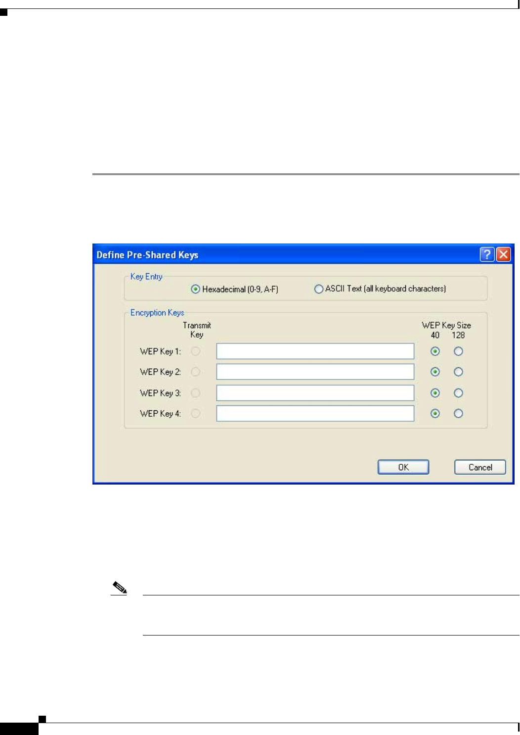
BETA DRAFT - CISCO CONFIDENTIAL
5-20
Cisco Aironet 802.11a/b/g Wireless LAN Client Adapters (CB21AG and PI21AG) Installation and Configuration Guide OL-4211-01
Chapter 5 Configuring the Client Adapter
Setting Security Parameters
Using Static WEP
This section provides instructions for entering new static WEP keys or overwriting existing static WEP
keys.
Entering a New Static WEP Key
Follow the steps below to enter a new static WEP key for this profile.
Step 1 Select Pre-Shared Key (Static WEP) on the Profile Management (Security) screen.
Step 2 Click Configure. The Define Pre-Shared Keys screen appears (see Figure 5-5).
Figure 5-5 Define Pre-Shared Keys Screen
Step 3 Select one of the following WEP key entry methods:
•Hexadecimal (0-9, A-F)—Specifies that the WEP key will be entered in hexadecimal characters,
which include 0-9, A-F, and a-f.
•ASCII Text (all keyboard characters)—Specifies that the WEP key will be entered in ASCII text,
which includes alpha characters, numbers, and punctuation marks.
Note ASCII text WEP keys are not supported on the Cisco Aironet 1200 Series Access Points, so
you must select the Hexadecimal (0-9, A-F) option if you are planning to use your client
adapter with these access points.
Step 4 For the static WEP key that you are entering (1, 2, 3, or 4), select a WEP key size of 40 or 128 on the
right side of the screen. 128-bit client adapters can use 40- or 128-bit keys, but 40-bit adapters can use
only 40-bit keys. If 128 bit is not supported by the client adapter, this option is unavailable.

BETA DRAFT - CISCO CONFIDENTIAL
5-21
Cisco Aironet 802.11a/b/g Wireless LAN Client Adapters (CB21AG and PI21AG) Installation and Configuration Guide
OL-4211-01
Chapter 5 Configuring the Client Adapter Setting Security Parameters
Step 5 Obtain the static WEP key from your system administrator and enter it in the blank field for the key you
are creating. Follow the guidelines below to enter a new static WEP key:
•WEP keys must contain the following number of characters:
–
10 hexadecimal characters or 5 ASCII text characters for 40-bit keys
Example: 5A5A313859 (hexadecimal) or ZZ18Y (ASCII)
–
26 hexadecimal characters or 13 ASCII text characters for 128-bit keys
Example: 5A583135333554595549333534 (hexadecimal) or ZX1535TYUI354 (ASCII)
Note You must enter hexadecimal characters for 5-GHz client adapters if these adapters will be
used with Cisco Aironet 1200 Series Access Points.
•Your client adapter’s WEP key must match the WEP key used by the access point (in infrastructure
mode) or clients (in ad hoc mode) with which you are planning to communicate.
•When setting more than one WEP key, the keys must be assigned to the same WEP key numbers for
all devices. For example, WEP key 2 must be WEP key number 2 on all devices. When multiple
WEP keys are set, they must be in the same order on all devices.
Note After you enter a WEP key, you can write over it, but you cannot edit or delete it.
Step 6 Click the Transmit Key button to the left of the key you want to use to transmit packets. Only one WEP
key can be selected as the transmit key.
Step 7 Click OK to save your changes and return to the Profile Management (Security) screen.
Step 8 Click OK to return to the Cisco Aironet Desktop Utility (Profile Management) screen.
Overwriting an Existing Static WEP Key
Follow the steps below to overwrite an existing static WEP key.
Note You can overwrite existing WEP keys, but you cannot edit or delete them.
Step 1 Select Pre-Shared Key (Static WEP) on the Profile Management (Security) screen.
Step 2 Click Configure. The Define Pre-Shared Keys screen appears (see Figure 5-5).
Step 3 Look at the current WEP key settings in the middle of the screen. All existing static WEP keys are
displayed as asterisks for security reasons.
Step 4 Decide which existing static WEP key you want to overwrite.
Step 5 Click within the field for that key and delete the asterisks.
Step 6 Enter a new key, following the guidelines outlined in Step 5 of the “Entering a New Static WEP Key”
section on page 5-20.
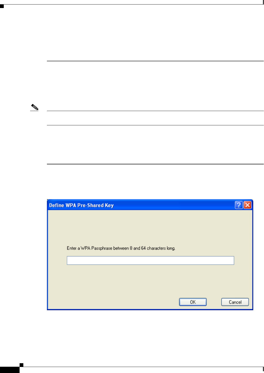
BETA DRAFT - CISCO CONFIDENTIAL
5-22
Cisco Aironet 802.11a/b/g Wireless LAN Client Adapters (CB21AG and PI21AG) Installation and Configuration Guide OL-4211-01
Chapter 5 Configuring the Client Adapter
Setting Security Parameters
Step 7 Make sure the Transmit Key button to the left of your key is selected, if you want this key to be used to
transmit packets.
Step 8 Click OK to save your changes and return to the Profile Management (Security) screen.
Step 9 Click OK to return to the Cisco Aironet Desktop Utility (Profile Management) screen.
Disabling Static WEP
If you ever need to disable static WEP for a particular profile, select None on the Profile Management
(Security) screen and click OK.
Note Selecting any of the other security options on the Profile Management (Security) screen disables static
WEP automatically.
Using a WPA Passphrase
Follow the steps below to enter a WPA passphrase (also known as a WPA pre-shared key) for this profile.
Step 1 Select WPA Passphrase on the Profile Management (Security) screen.
Step 2 Click Configure. The Define WPA Pre-Shared Key screen appears (see Figure 5-6).
Figure 5-6 Define WPA Pre-Shared Key Screen

BETA DRAFT - CISCO CONFIDENTIAL
5-23
Cisco Aironet 802.11a/b/g Wireless LAN Client Adapters (CB21AG and PI21AG) Installation and Configuration Guide
OL-4211-01
Chapter 5 Configuring the Client Adapter Setting Security Parameters
Step 3 Obtain the WPA passphrase for the access point (in an infrastructure network) or other clients (in an ad
hoc network) from your system administrator and enter it in the WPA Passphrase field. Follow the
guidelines below to enter a WPA passphrase:
•WPA passphrases must contain 8 to 63 ASCII text characters or 64 hexadecimal characters.
•Your client adapter’s WPA passphrase must match the passphrase used by the access point (in
infrastructure mode) or clients (in ad hoc mode) with which you are planning to communicate.
Step 4 Click OK to save your changes and return to the Profile Management (Security) screen.
Step 5 Click OK to return to the Cisco Aironet Desktop Utility (Profile Management) screen.
Enabling LEAP
Before you can enable LEAP authentication, your network devices must meet the following
requirements:
•Client adapters must support WEP and use the drivers and utilities included in the Install Wizard file.
•Access points to which your client adapter may attempt to authenticate must use the following
firmware versions or greater: 11.23T (340 and 350 series access points), 11.54T (1200 series access
points), or IOS release 12.2(4)JA (1100 series access points).
Note To use WPA, access points must use IOS release 12.2(11)JA or greater. To use the Reporting
Access Points That Fail LEAP Authentication and Fast Roaming features, access points
must use the firmware versions listed on page 5-17.
•All necessary infrastructure devices (for example, access points, servers, etc.) must be properly
configured for LEAP authentication.
Follow the steps below to enable LEAP authentication for this profile.
Step 1 Perform one of the following:
•If you want to enable LEAP without WPA, select 802.1x under Set Security Options and LEAP in
the 802.1x EAP Type drop-down box.
•If you want to enable LEAP with WPA, select WPA under Set Security Options and LEAP in the
WPA EAP Type drop-down box.
Step 2 Click Configure. The LEAP Settings screen appears (see Figure 5-7).
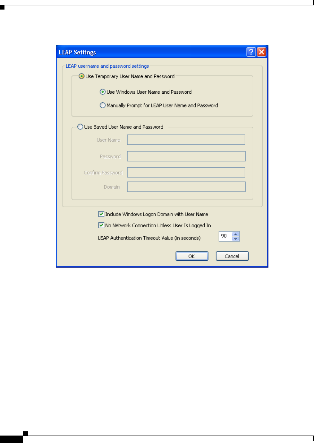
BETA DRAFT - CISCO CONFIDENTIAL
5-24
Cisco Aironet 802.11a/b/g Wireless LAN Client Adapters (CB21AG and PI21AG) Installation and Configuration Guide OL-4211-01
Chapter 5 Configuring the Client Adapter
Setting Security Parameters
Figure 5-7 LEAP Settings Screen
Step 3 Select one of the following LEAP username and password setting options:
•Use Temporary User Name and Password—Requires you to enter the LEAP username and
password each time the computer reboots in order to authenticate and gain access to the network.
•Use Saved User Name and Password—Does not require you to enter a LEAP username and
password each time the computer reboots. Authentication occurs automatically as needed using a
saved username and password (which are registered with the RADIUS server).

BETA DRAFT - CISCO CONFIDENTIAL
5-25
Cisco Aironet 802.11a/b/g Wireless LAN Client Adapters (CB21AG and PI21AG) Installation and Configuration Guide
OL-4211-01
Chapter 5 Configuring the Client Adapter Setting Security Parameters
Step 4 Perform one of the following:
•If you selected Use Temporary User Name and Password in Step 3, select one of the following
options:
–
Use Windows User Name and Password—Causes your Windows username and password to
also serve as your LEAP username and password, giving you only one set of credentials to
remember. After you log in, the LEAP authentication process begins automatically. This is the
default setting.
–
Manually Prompt for LEAP User Name and Password—Requires you to manually invoke
the LEAP authentication process as needed using the Manual LEAP Login option in the Action
drop-down menu or in ASTU. You are not prompted to enter a LEAP username and password
during the Windows login. This option might be used to support a software token one-time
password system or other systems that require additional software that is not available at login.
•If you selected Use Saved User Name and Password in Step 3, follow the steps below:
a. Enter a username and password in the appropriate fields.
Note Usernames and passwords are limited to 32 ASCII characters each. However, if a
domain name is entered in the Domain field, the sum of the username and domain name
is limited to 31 ASCII characters.
b. Re-enter the password in the Confirm Password field.
c. If you wish to specify a domain name that will be passed to the RADIUS server along with your
username, enter it in the Domain field.
Step 5 If you work in an environment with multiple domains and, therefore, want your Windows login domain
to be passed to the RADIUS server along with your username, check the Include Windows Logon
Domain with User Name check box. The default setting is checked.
Note This check box is available only if you selected to use a temporary username and password.
Step 6 If you want to force the client adapter to disassociate after you log off so that another user cannot gain
access to the wireless network using your credentials, check the No Network Connection Unless User
Is Logged In check box. The default setting is checked.
Step 7 In the LEAP Authentication Timeout Value field, select the amount of time (in seconds) before a LEAP
authentication is considered to be failed and an error message appears.
Range: 30 to 500 seconds
Default: 90 seconds
Step 8 Click OK to save your changes and return to the Profile Management (Security) screen.
Step 9 Click OK to return to the Cisco Aironet Desktop Utility (Profile Management) screen.

BETA DRAFT - CISCO CONFIDENTIAL
5-26
Cisco Aironet 802.11a/b/g Wireless LAN Client Adapters (CB21AG and PI21AG) Installation and Configuration Guide OL-4211-01
Chapter 5 Configuring the Client Adapter
Setting Security Parameters
Step 10 Follow the steps below if you want to take advantage of the fast roaming feature:
a. Perform one of the following steps, depending on your computer’s operating system:
–
If your computer is running Windows 2000, double-click My Computer, Control Panel, and
Network and Dial-up Connections. Right-click Local Area Connection. Click Properties.
The Local Area Connection Properties screen appears.
–
If your computer is running Windows XP, double-click My Computer, Control Panel, and
Network Connections. Right-click Wireless Network Connection. Click Properties. The
Wireless Network Connection Properties screen appears. Select the Wireless Networks tab.
Make sure the Use Windows to configure my wireless network settings check box is checked.
Select the SSID of the profile you are creating from the list of available networks and click
Configure. If your profile’s SSID is not listed, click Add, enter your profile’s SSID in the
Network name (SSID) field.
b. Click the Authentication tab.
c. Uncheck the Enable network access control using IEEE 802.1X or Enable IEEE 802.1x
authentication for this network check box.
d. Click OK to save your settings.
e. If you are using Windows XP, uncheck the Use Windows to configure my wireless network
settings check box on the Wireless Networks screen and click OK.
Step 11 Refer to Chapter 6 for instructions on authenticating using LEAP.
Enabling EAP-TLS or PEAP
Before you can enable EAP-TLS or PEAP authentication, your network devices must meet the following
requirements:
•Client adapters must support WEP and use the drivers and utilities included in the Install Wizard file.
•Access points to which your client adapter may attempt to authenticate must use the following
firmware versions or greater: 12.00T (340, 350, and 1200 series access points) or IOS release
12.2(4)JA (1100 series access points).
Note To use WPA, access points must use IOS release 12.2(11)JA or greater.
•All necessary infrastructure devices (for example, access points, servers, gateways, user databases,
etc.) must be properly configured for the authentication type you plan to enable on the client.
Follow the instructions in one of the sections below to enable EAP-TLS or PEAP authentication for this
profile:
•Enabling EAP-TLS, page 5-27
•Enabling PEAP (EAP-MSCHAP V2), page 5-28
•Enabling PEAP (EAP-GTC), page 5-29
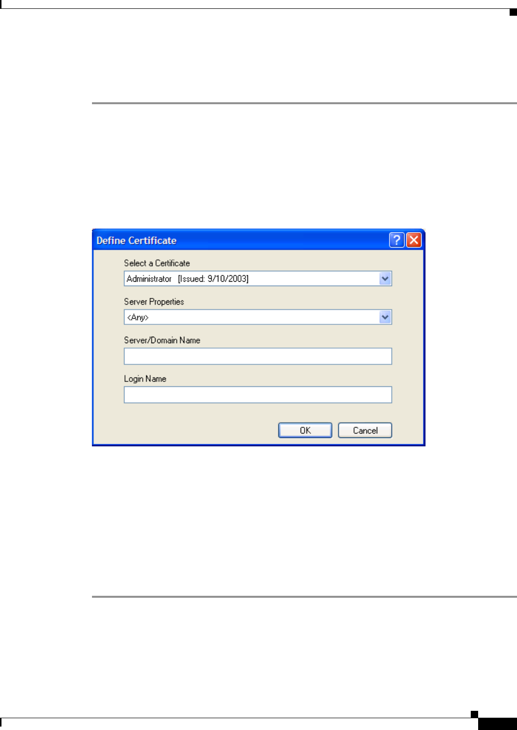
BETA DRAFT - CISCO CONFIDENTIAL
5-27
Cisco Aironet 802.11a/b/g Wireless LAN Client Adapters (CB21AG and PI21AG) Installation and Configuration Guide
OL-4211-01
Chapter 5 Configuring the Client Adapter Setting Security Parameters
Enabling EAP-TLS
Follow the steps below to enable EAP-TLS authentication for this profile.
Step 1 Perform one of the following:
•If you want to enable EAP-TLS without WPA, select 802.1x under Set Security Options and
EAP-TLS in the 802.1x EAP Type drop-down box.
•If you want to enable EAP-TLS with WPA, select WPA under Set Security Options and EAP-TLS
in the WPA EAP Type drop-down box.
Step 2 Click Configure. The Define Certificate screen appears (see Figure 5-8).
Figure 5-8 Define Certificate Screen
Step 3 Select your server certificate in the Select a Certificate drop-down list.
Step 4 Select the certificate authority from which the server certificate was downloaded in the Server Properties
drop-down list.
Step 5 Enter the domain name and username that will be used for authentication, if they are not retrieved
automatically from the certificate.
Step 6 Click OK twice to save your changes and return to the Cisco Aironet Desktop Utility (Profile
Management) screen. The configuration is complete.
Step 7 Refer to Chapter 6 for instructions on authenticating using EAP-TLS.
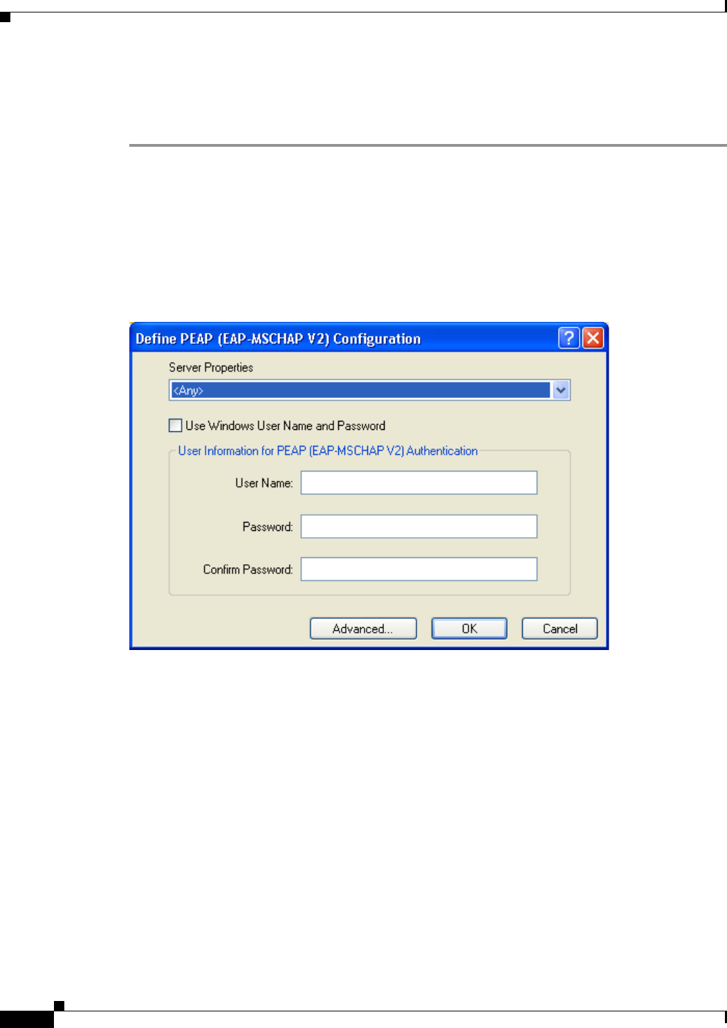
BETA DRAFT - CISCO CONFIDENTIAL
5-28
Cisco Aironet 802.11a/b/g Wireless LAN Client Adapters (CB21AG and PI21AG) Installation and Configuration Guide OL-4211-01
Chapter 5 Configuring the Client Adapter
Setting Security Parameters
Enabling PEAP (EAP-MSCHAP V2)
Follow the steps below to enable PEAP (EAP-MSCHAP V2) for this profile.
Step 1 Perform one of the following:
•If you want to enable PEAP (EAP-MSCHAP V2) without WPA, select 802.1x under Set Security
Options and PEAP (EAP-MSCHAP V2) in the 802.1x EAP Type drop-down box.
•If you want to enable PEAP (EAP-MSCHAP V2) with WPA, select WPA under Set Security
Options and PEAP (EAP-MSCHAP V2) in the WPA EAP Type drop-down box.
Step 2 Click Configure. The Define PEAP (EAP-MSCHAP V2) Configuration screen appears (see Figure 5-9).
Figure 5-9 Define PEAP (EAP-MSCHAP V2) Configuration Screen
Step 3 Select the certificate authority from which the server certificate was downloaded in the Server Properties
drop-down list.
Step 4 Perform one of the following:
•If you want your Windows username and password to also serve as your PEAP username and
password, check the Use Windows User Name and Password check box.
This option gives you only one set of credentials to remember. After you log in, the PEAP
authentication process begins automatically.
•If you want to enter a separate PEAP username and password (which are registered with the
RADIUS server) in addition to your regular Windows login in order to start the PEAP authentication
process, follow the steps below:
a. Enter your PEAP (EAP-MSCHAP V2) authentication username and password in the
corresponding fields.
b. Re-enter your password in the Confirm Password field.
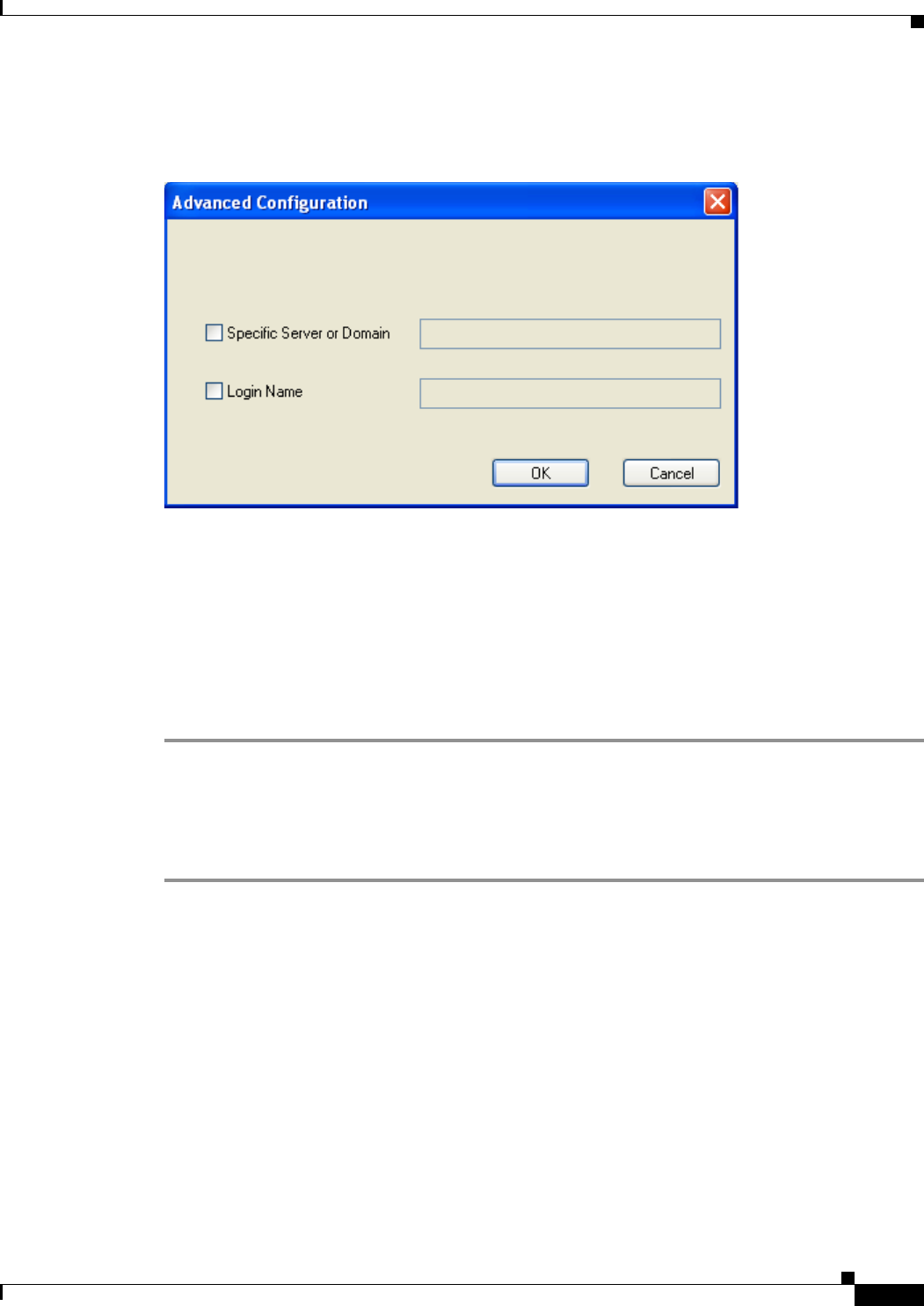
BETA DRAFT - CISCO CONFIDENTIAL
5-29
Cisco Aironet 802.11a/b/g Wireless LAN Client Adapters (CB21AG and PI21AG) Installation and Configuration Guide
OL-4211-01
Chapter 5 Configuring the Client Adapter Setting Security Parameters
Step 5 Click Advanced. The Advanced Configuration screen appears (see Figure 5-10).
Figure 5-10 Advanced Configuration Screen
Step 6 If you want to specify the server or domain that will be used for authentication, check the Specific
Server or Domain check box and enter the server or domain name in the corresponding edit box.
Step 7 If you want to specify the username that will be used for authentication, check the Login Name check
box and enter the username in the Login Name edit box.
Step 8 Click OK three times to save your changes and return to the Cisco Aironet Desktop Utility (Profile
Management) screen. The configuration is complete.
Step 9 Refer to Chapter 6 for instructions on authenticating using PEAP.
Enabling PEAP (EAP-GTC)
Follow the steps below to enable PEAP (EAP-GTC) for this profile.
Step 1 Perform one of the following:
•If you want to enable PEAP (EAP-GTC) without WPA, select 802.1x under Set Security Options
and PEAP (EAP-GTC) in the 802.1x EAP Type drop-down box.
•If you want to enable PEAP (EAP-GTC) with WPA, select WPA under Set Security Options and
PEAP (EAP-GTC) in the WPA EAP Type drop-down box.
Step 2 Click Configure. The Define PEAP (EAP-GTC) Configuration screen appears (see Figure 5-11).
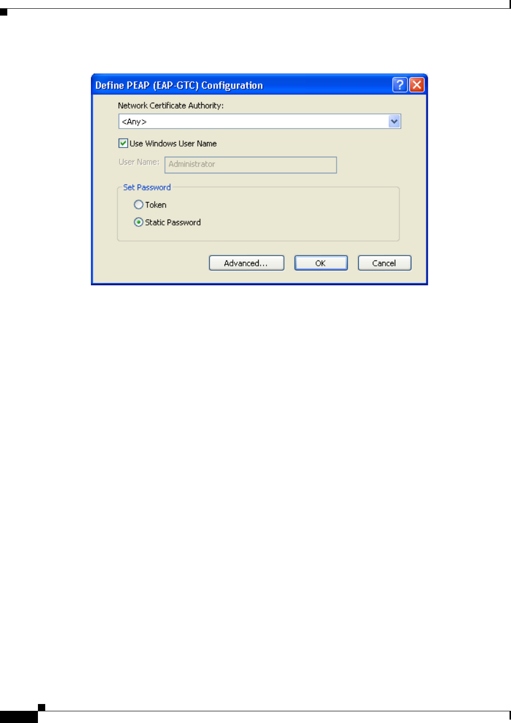
BETA DRAFT - CISCO CONFIDENTIAL
5-30
Cisco Aironet 802.11a/b/g Wireless LAN Client Adapters (CB21AG and PI21AG) Installation and Configuration Guide OL-4211-01
Chapter 5 Configuring the Client Adapter
Setting Security Parameters
Figure 5-11 Define PEAP (EAP-GTC) Configuration Screen
Step 3 Select the certificate authority from which the server certificate was downloaded in the Network
Certificate Authority drop-down list.
Step 4 Perform one of the following:
•If you want your Windows username to also serve as your PEAP username, check the Use Windows
User Name check box.
This option gives you only one username to remember. After you log in, the PEAP authentication
process begins automatically.
•If you want to enter a separate PEAP username (which is registered with the RADIUS server) in
addition to your regular Windows username in order to start the PEAP authentication process, enter
your PEAP username in the User Name field.
Step 5 Select either Token or Static Password, depending on your user database.
Step 6 Click Advanced. The Advanced Configuration screen appears (see Figure 5-12).
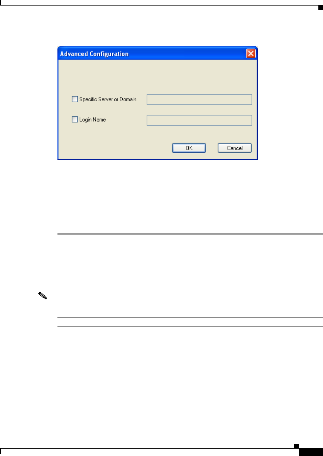
BETA DRAFT - CISCO CONFIDENTIAL
5-31
Cisco Aironet 802.11a/b/g Wireless LAN Client Adapters (CB21AG and PI21AG) Installation and Configuration Guide
OL-4211-01
Chapter 5 Configuring the Client Adapter Setting Security Parameters
Figure 5-12 Advanced Configuration Screen
Step 7 If you want to specify the server or domain that will be used for authentication, check the Specific
Server or Domain check box and enter the server or domain name in the corresponding edit box.
Step 8 If you want to specify the username that will be used for authentication, check the Login Name check
box and enter the username in the Login Name edit box.
Step 9 Click OK three times to save your settings. The configuration is complete.
Step 10 Refer to Chapter 6 for instructions on authenticating using PEAP.
Disabling EAP
If you ever need to disable EAP authentication (LEAP, EAP-TLS, or PEAP) for a particular profile,
select None on the Profile Management (Security) screen and click OK.
Note Selecting Pre-Shared Key (Static WEP) or WPA Passphrase on the Profile Management (Security)
screen disables EAP automatically.

BETA DRAFT - CISCO CONFIDENTIAL
5-32
Cisco Aironet 802.11a/b/g Wireless LAN Client Adapters (CB21AG and PI21AG) Installation and Configuration Guide OL-4211-01
Chapter 5 Configuring the Client Adapter
Setting Security Parameters

CHAPTER
ALPHA DRAFT - CISCO CONFIDENTIAL
6-1
Cisco Aironet 802.11a/b/g Wireless LAN Client Adapters (CB21AG and PI21AG) Installation and Configuration Guide
OL-4211-01
6
Using EAP Authentication
This chapter explains the sequence of events that occurs and the actions you must take when a profile
that is set for EAP authentication is selected for use.
The following topics are covered in this chapter:
•Overview, page 6-2
•Using LEAP, page 6-2
•Using LEAP with the Windows Username and Password, page 6-3
•Using LEAP with a Manually Prompted Login, page 6-5
•Using LEAP with a Saved Username and Password, page 6-8
•Using EAP-TLS, page 6-9
•Using PEAP, page 6-10
•Restarting the Authentication Process, page 6-12
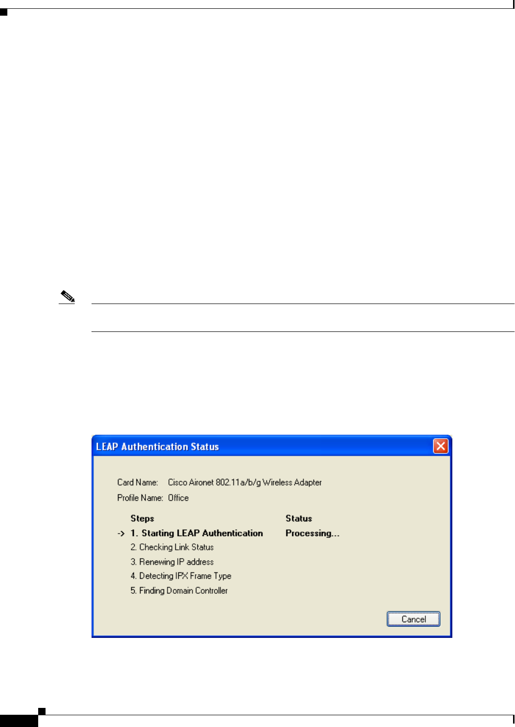
ALPHA DRAFT - CISCO CONFIDENTIAL
6-2
Cisco Aironet 802.11a/b/g Wireless LAN Client Adapters (CB21AG and PI21AG) Installation and Configuration Guide OL-4211-01
Chapter 6 Using EAP Authentication
Overview
Overview
This chapter explains the sequence of events that occurs as soon as you or ADU’s auto profile selection
feature selects a profile that uses EAP authentication as well as after you eject and reinsert the client
adapter, reboot the computer, log on while this profile is selected, or are informed that your username
and password have expired. The chapter contains five sections based on the profile’s authentication type
and its username and password settings:
•LEAP with the Windows username and password, page 6-3
•LEAP with a manually prompted login, page 6-5
•LEAP with a saved username and password, page 6-8
•EAP-TLS, page 6-9
•PEAP, page 6-10
Also provided are an overview of LEAP authentication (below) and instructions for restarting the
authentication process when necessary (page 6-12).
Follow the instructions for your profile’s authentication type and credential settings to successfully
authenticate.
Note If any error messages appear during authentication, refer to Chapter 10 for explanations and
recommended actions.
Using LEAP
When LEAP authentication begins, the LEAP Authentication Status screen appears (see Figure 6-1).
Figure 6-1 LEAP Authentication Status Screen

ALPHA DRAFT - CISCO CONFIDENTIAL
6-3
Cisco Aironet 802.11a/b/g Wireless LAN Client Adapters (CB21AG and PI21AG) Installation and Configuration Guide
OL-4211-01
Chapter 6 Using EAP Authentication Using LEAP with the Windows Username and Password
This screen provides information about the status of LEAP authentication. Table 6-1 lists and explains
the stages of LEAP authentication. As each stage is completed, a status message (such as Success)
appears in the Status field. If any error messages appear, refer to the “Error Messages” section on
page 10-11 for an explanation and the recommended action to take.
Using LEAP with the Windows Username and Password
After Profile Selection or Card Insertion
After you (or auto profile selection) select a profile that uses LEAP authentication and specifies that your
Windows username and password also serve as your LEAP username and password or you eject and
reinsert the client adapter while this profile is selected, the following events occur:
1. The LEAP Authentication Status screen appears.
2. If your client adapter authenticates, the screen shows that each stage was successful and then
disappears. ASTU now shows Authenticated, and the Server Based Authentication field on the ADU
Current Status screen shows LEAP.
If the authentication attempt fails, an error message appears after the LEAP timeout period has
expired. Refer to the “Error Messages” section on page 10-11 for the necessary action to take.
Table 6-1 Stages of LEAP Authentication
Stage Explanation
Starting LEAP Authentication The client adapter associates to an access point, and the LEAP
authentication process begins.
Checking Link Status The client adapter is LEAP authenticated, and the network
connection is verified.
Renewing IP Address If DHCP is enabled, the IP address is released and renewed.
Detecting IPX Frame Type The IPX frame type is reset if AutoDetect is enabled.
Finding Domain Controller If you are logging into a domain and the active profile
specifies that the domain name be included, an attempt is
made to find the domain controller to make sure subsequent
access to the domain is successful.

ALPHA DRAFT - CISCO CONFIDENTIAL
6-4
Cisco Aironet 802.11a/b/g Wireless LAN Client Adapters (CB21AG and PI21AG) Installation and Configuration Guide OL-4211-01
Chapter 6 Using EAP Authentication
Using LEAP with the Windows Username and Password
After a Reboot or Logon
After your computer reboots or you log on, follow the steps below to LEAP authenticate.
Step 1 When the Windows login screen appears, enter your Windows username and password and click OK.
The domain name is optional.
Note If your computer has Novell Client 32 software installed, a separate LEAP login screen appears
before the Novell login screen. If this occurs, enter your Windows and Novell username and
password in the login screens and click OK.
The LEAP Authentication Status screen appears.
Step 2 If your client adapter authenticates, the screen shows that each stage was successful and then disappears.
ASTU now shows Authenticated, and the Server Based Authentication field on the ADU Current Status
screen shows LEAP.
If the authentication attempt fails, an error message appears after the LEAP timeout period has expired.
Refer to the “Error Messages” section on page 10-11 for the necessary action to take.
Step 3 Windows continues to log you onto the system.
After Your LEAP Credentials Expire
If the LEAP credentials (username and password) for your current profile expire or become invalid,
follow the steps below to reauthenticate.
Note If you change your Windows password using the standard Windows Change Password function, the
client updates the LEAP password automatically and maintains its connection to the access point if the
current profile uses the Windows username and password.
Step 1 Click OK when the following message appears: “The user name and password entered are no longer valid
and have failed the LEAP authentication process. Please enter a new user name and password.”
Step 2 When the Windows login screen appears, enter your new username and password and click OK. The
client adapter should authenticate using your new credentials.
Note If you click Cancel rather than OK on the Windows login screen, the following message appears:
“The profile will be disabled until you select the Reauthenticate option, Windows restarts, or the
card is ejected and reinserted. Are you sure?” If you click No, the Windows login screen
reappears and allows you to enter your new credentials. If you click Yes, the current profile is
disabled until you select Reauthenticate from ASTU or the Action drop-down menu in ADU,
reboot your computer, or eject and reinsert the card.
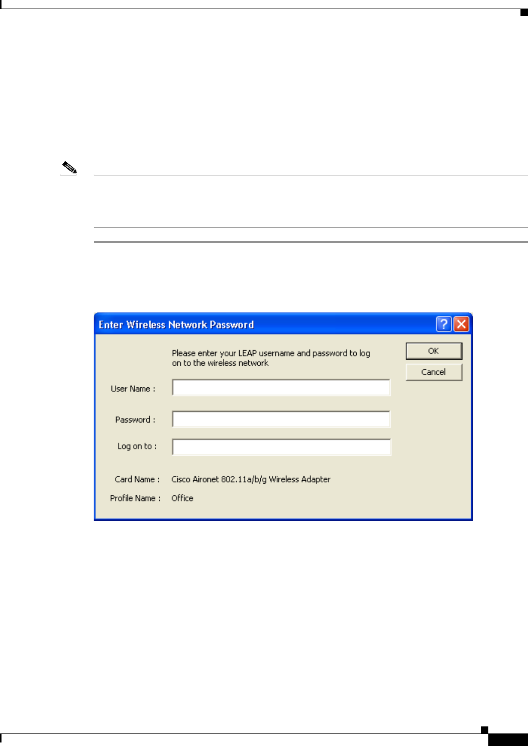
ALPHA DRAFT - CISCO CONFIDENTIAL
6-5
Cisco Aironet 802.11a/b/g Wireless LAN Client Adapters (CB21AG and PI21AG) Installation and Configuration Guide
OL-4211-01
Chapter 6 Using EAP Authentication Using LEAP with a Manually Prompted Login
Using LEAP with a Manually Prompted Login
After Profile Selection
After you (or auto profile selection) select a profile that uses LEAP authentication but specifies that the
process be manually invoked, follow the steps below to LEAP authenticate.
Note This procedure is applicable the first time a manual LEAP profile is selected. After you follow the steps
below to enter your LEAP credentials, you can switch profiles without having to re-enter your
credentials until you reboot your computer, eject and reinsert your client adapter, or change the profile
in any way (including its priority in auto profile selection).
Step 1 Perform one of the following:
•If you activate a manual LEAP profile, the LEAP login screen appears (see Figure 6-2).
Figure 6-2 LEAP Login Screen
Enter your LEAP username and password and click OK. The domain name is optional.
•If auto profile selection selects a manual LEAP profile, you must select the Manual LEAP Login
option from ASTU or the Action drop-down menu (see Figure 6-3).
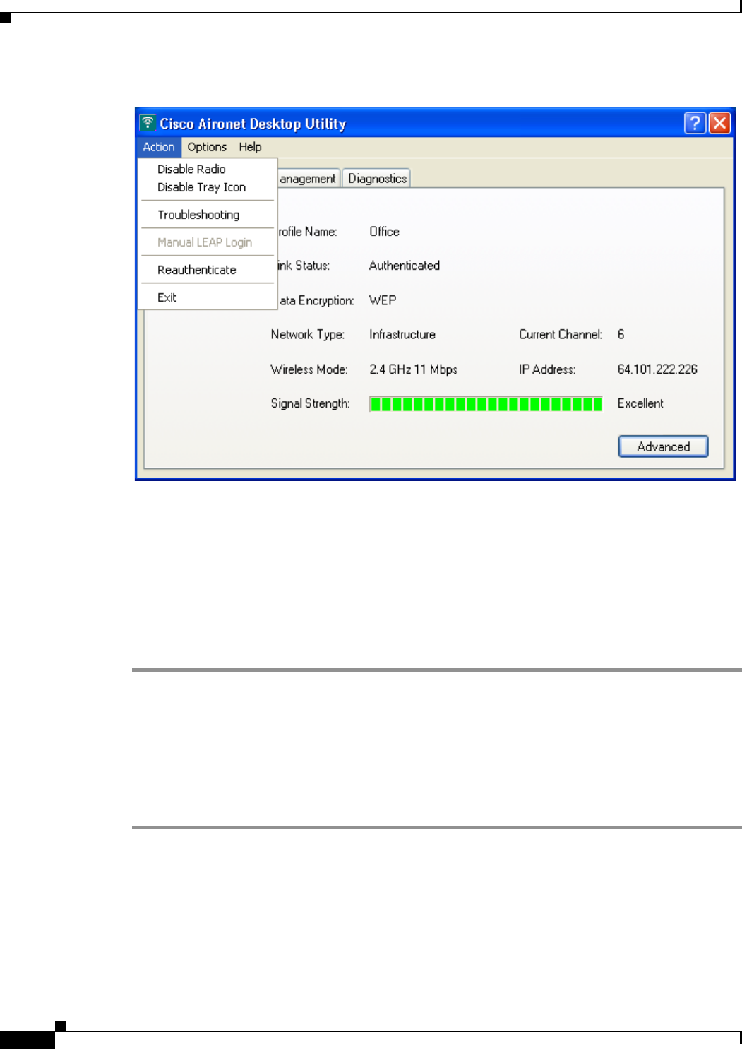
ALPHA DRAFT - CISCO CONFIDENTIAL
6-6
Cisco Aironet 802.11a/b/g Wireless LAN Client Adapters (CB21AG and PI21AG) Installation and Configuration Guide OL-4211-01
Chapter 6 Using EAP Authentication
Using LEAP with a Manually Prompted Login
Figure 6-3 Action Drop-Down Menu
When the LEAP login screen appears (see Figure 6-2), enter your LEAP username and password
and click OK. The domain name is optional.
Step 2 The LEAP Authentication Status screen appears. If your client adapter authenticates, the screen shows
that each stage was successful and then disappears. ASTU now shows Authenticated, and the Server
Based Authentication field on the ADU Current Status screen shows LEAP.
If the authentication attempt fails, an error message appears after the LEAP timeout period has expired.
Refer to the “Error Messages” section on page 10-11 for the necessary action to take.
After a Reboot, Logon, or Card Insertion
After your computer reboots, you log on, or you eject and reinsert the client adapter, the adapter does
not automatically attempt to authenticate. You must manually invoke the authentication process. To do
so, follow the steps below.
Step 1 If you rebooted your computer or logged on, complete your standard Windows login.
Step 2 Open ASTU or ADU.
Step 3 Select the Manual LEAP Login option.
Step 4 When the LEAP login screen appears (see Figure 6-4), enter your LEAP username and password and
click OK. The domain name is optional.
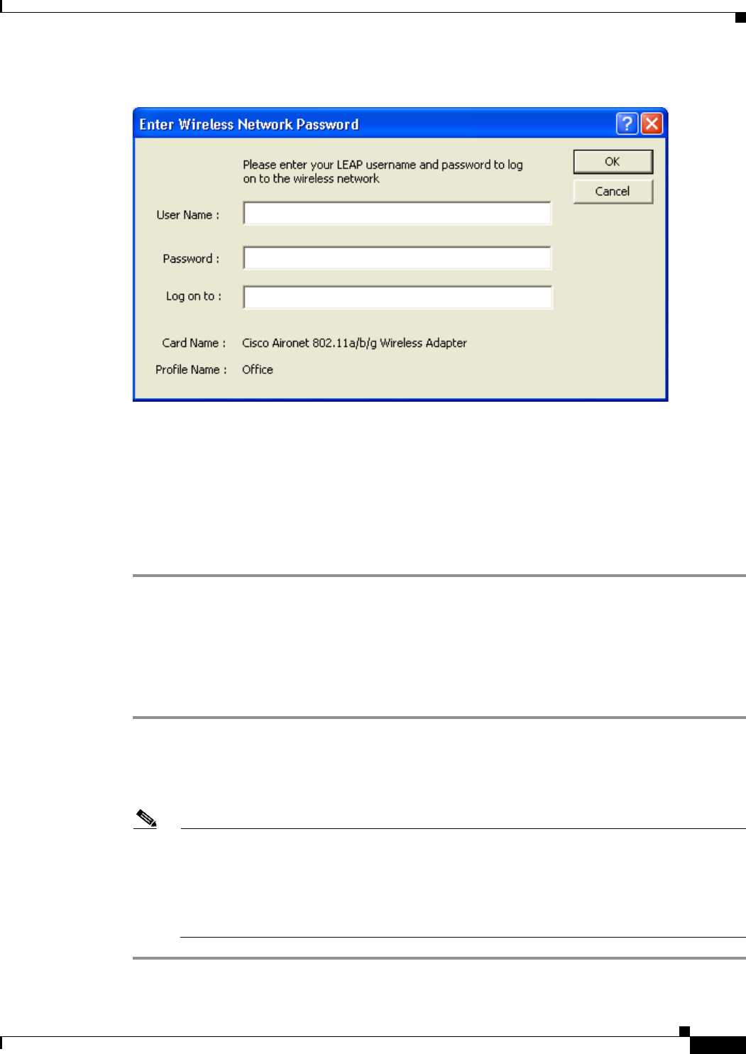
ALPHA DRAFT - CISCO CONFIDENTIAL
6-7
Cisco Aironet 802.11a/b/g Wireless LAN Client Adapters (CB21AG and PI21AG) Installation and Configuration Guide
OL-4211-01
Chapter 6 Using EAP Authentication Using LEAP with a Manually Prompted Login
Figure 6-4 LEAP Login Screen
The LEAP Authentication Status screen appears.
Step 5 If your client adapter authenticates, the screen shows that each stage was successful and then disappears.
ASTU now shows Authenticated, and the Server Based Authentication field on the ADU Current Status
screen shows LEAP.
If the authentication attempt fails, an error message appears after the LEAP timeout period has expired.
Refer to the “Error Messages” section on page 10-11 for the necessary action to take.
After Your LEAP Credentials Expire
If the LEAP credentials (username and password) for your current profile expire or become invalid,
follow the steps below to reauthenticate.
Step 1 Click OK when the following message appears: “The user name and password entered are no longer valid
and have failed the LEAP authentication process. Please enter a new user name and password.”
Step 2 When the LEAP login screen appears, enter your new username and password and click OK. The client
adapter should authenticate using your new credentials.
Note If you click Cancel rather than OK on the LEAP login screen, the following message appears:
“The profile will be disabled until you select the Reauthenticate option, Windows restarts, or the
card is ejected and reinserted. Are you sure?” If you click No, the LEAP login screen reappears
and allows you to enter your new credentials. If you click Yes, the current profile is disabled until
you select Reauthenticate from ASTU or the Action drop-down menu in ADU, reboot your
computer, or eject and reinsert the card.

ALPHA DRAFT - CISCO CONFIDENTIAL
6-8
Cisco Aironet 802.11a/b/g Wireless LAN Client Adapters (CB21AG and PI21AG) Installation and Configuration Guide OL-4211-01
Chapter 6 Using EAP Authentication
Using LEAP with a Saved Username and Password
Using LEAP with a Saved Username and Password
After Profile Selection or Card Insertion
After you (or auto profile selection) select a profile that uses LEAP authentication with a saved LEAP
username and password or you eject and reinsert the client adapter while this profile is selected, the
following events occur:
1. The LEAP Authentication Status screen appears.
2. If your client adapter authenticates, the screen shows that each stage was successful and then
disappears. ASTU now shows Authenticated, and the Server Based Authentication field on the ADU
Current Status screen shows LEAP.
If the authentication attempt fails, an error message appears after the LEAP timeout period has
expired. Refer to the “Error Messages” section on page 10-11 for the necessary action to take.
After a Reboot or Logon
After your computer reboots or you log on, the following events occur:
1. After you enter your Windows username and password, the LEAP authentication process begins
automatically using your saved LEAP username and password.
Note If you unchecked the No Network Connection Unless User Is Logged In check box on the
LEAP Settings screen, the LEAP authentication process begins before the Windows login
screen appears.
2. If your client adapter authenticates, the screen shows that each stage was successful and then
disappears. ASTU now shows Authenticated, and the Server Based Authentication field on the ADU
Current Status screen shows LEAP.
If the authentication attempt fails, an error message appears after the LEAP timeout period has
expired. Refer to the “Error Messages” section on page 10-11 for the necessary action to take.
3. Windows continues to log you onto the system.
After Your LEAP Credentials Expire
If the LEAP credentials (username and password) for your current profile expire or become invalid,
follow the steps below to reauthenticate.
Step 1 Click OK when the following message appears: “The saved user name and password entered for this profile
are no longer valid and have failed the LEAP authentication process. Please enter a new user name and
password. Remember to change them permanently in the profile using the ADU Profile Manager.”
Step 2 When the LEAP login screen appears, enter your new username and password and click OK. The client
adapter should authenticate using your new credentials.

ALPHA DRAFT - CISCO CONFIDENTIAL
6-9
Cisco Aironet 802.11a/b/g Wireless LAN Client Adapters (CB21AG and PI21AG) Installation and Configuration Guide
OL-4211-01
Chapter 6 Using EAP Authentication Using EAP-TLS
Note If you click Cancel rather than OK on the LEAP login screen, the following message appears:
“The profile will be disabled until you select the Reauthenticate option, Windows restarts, or the
card is ejected and reinserted. Are you sure?” If you click No, the LEAP login screen reappears
and allows you to enter your new credentials. If you click Yes, the current profile is disabled until
you select Reauthenticate from ASTU or the Action drop-down menu in ADU, reboot your
computer, or eject and reinsert the card.
Step 3 Edit the profile in ADU by changing the saved username and password on the LEAP Settings screen.
Step 4 Click OK twice to save the changes to your profile.
Using EAP-TLS
After Profile Selection or Card Insertion
After you (or auto profile selection) select a profile that uses EAP-TLS authentication or you eject and
reinsert the client adapter while this profile is selected, follow the steps below to EAP authenticate.
Step 1 If your computer is running Windows XP and a pop-up message appears above the Windows system tray
informing you that you need to accept a certificate to begin the EAP authentication process, click the
message and follow the instructions provided to accept the certificate.
Note You should not have to accept a certificate for future authentication attempts. After you accept
one, the same certificate is used subsequently.
Step 2 If a message appears indicating the root certification authority for the server’s certificate, and it is the
correct certification authority, click OK to accept the connection. Otherwise, click Cancel.
Step 3 If a message appears indicating the server to which your client adapter is connected, and it is the correct
server to connect to, click OK to accept the connection. Otherwise, click Cancel.
Step 4 The client adapter should now EAP authenticate. If the authentication was successful, ASTU shows
Authenticated, and the Server Based Authentication field on the ADU Current Status screen shows
EAP-TLS.
If the authentication attempt fails, an error message appears. Refer to the “Error Messages” section on
page 10-11 for the necessary action to take.

ALPHA DRAFT - CISCO CONFIDENTIAL
6-10
Cisco Aironet 802.11a/b/g Wireless LAN Client Adapters (CB21AG and PI21AG) Installation and Configuration Guide OL-4211-01
Chapter 6 Using EAP Authentication
Using PEAP
After a Reboot or Logon
After your computer reboots or you log on using your Windows username and password, the EAP
authentication process begins automatically and the client adapter should EAP authenticate.
If the authentication was successful, ASTU shows Authenticated, and the Server Based Authentication
field on the ADU Current Status screen shows EAP-TLS.
If the authentication attempt fails, an error message appears. Refer to the “Error Messages” section on
page 10-11 for the necessary action to take.
Using PEAP
After Profile Selection, Card Insertion, Reboot, or Logon
After you (or auto profile selection) select a profile that uses PEAP authentication, follow the steps in
one of the sections below, depending on your user database, to EAP authenticate.
Note These instructions are applicable after profile selection, card ejection and re-insertion, reboot, or logon.
Windows NT or 2000 Domain Databases Only
Step 1 If your computer is running Windows XP, a pop-up message appears above the Windows system tray
informing you that you need to select a certificate or other credentials to access the network. Click this
message.
Step 2 If a message appears indicating the root certification authority for the server’s certificate and it is the
correct certification authority, click OK to accept the connection. Otherwise, click Cancel.
Step 3 If a message appears indicating the server to which your client adapter is connected and it is the correct
server to connect to, click OK to accept the connection. Otherwise, click Cancel.
Step 4 Perform one of the following:
•If your computer is running Windows 2000, the Static Password screen appears (see Figure 6-5).
•If your computer is running Windows XP, a pop-up message appears above the Windows system tray
prompting you to process your logon information for your wireless network. Click this message. The
Static Password screen appears (see Figure 6-5).
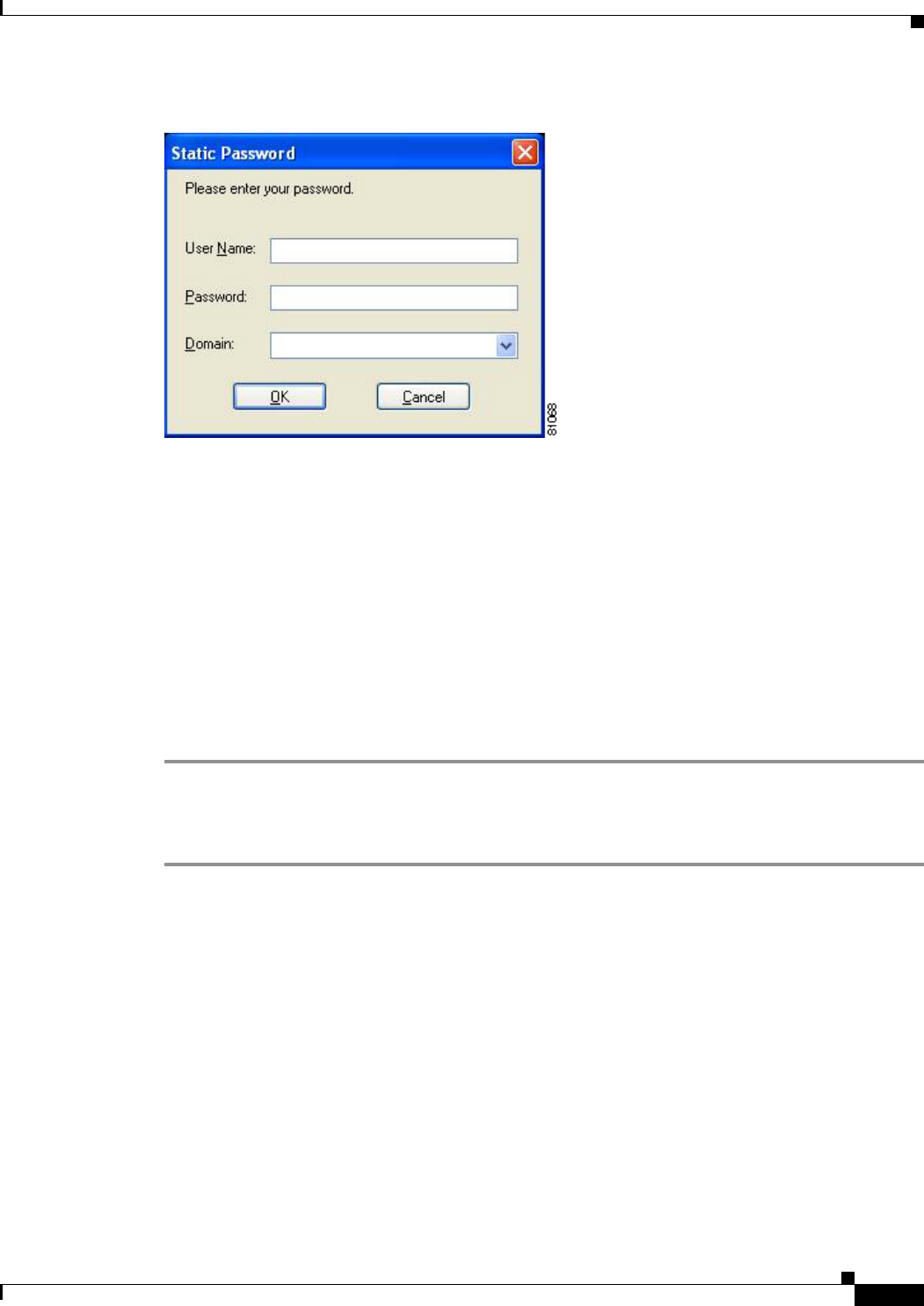
ALPHA DRAFT - CISCO CONFIDENTIAL
6-11
Cisco Aironet 802.11a/b/g Wireless LAN Client Adapters (CB21AG and PI21AG) Installation and Configuration Guide
OL-4211-01
Chapter 6 Using EAP Authentication Using PEAP
Figure 6-5 Static Password Screen
Step 5 Enter your PEAP authentication username and password (which are registered with the RADIUS server).
Step 6 If applicable, select your domain name from the drop-down list or type it in.
Step 7 Click OK. The PEAP Authentication Status screen appears.
If your client adapter authenticates, the screen shows that each stage was successful and then disappears.
ASTU now shows Authenticated, and the Server Based Authentication field on the ADU Current Status
screen shows PEAP.
If the authentication attempt fails, an error message appears. Refer to the “Error Messages” section on
page 10-11 for the necessary action to take.
Step 8 If you also have a locally cached Windows password, you must change it manually in Windows to
synchronize your passwords. To do so, press Ctrl-Alt-Delete, select Change Password, and enter your
old password once and your new password twice.
OTP Databases Only
Step 1 If your computer is running Windows XP, a pop-up message appears above the Windows system tray
informing you that you need to select a certificate or other credentials to access the network. Click this
message.
Step 2 If a message appears indicating the root certification authority for the server’s certificate and it is the
correct certification authority, click OK to accept the connection. Otherwise, click Cancel.
Step 3 If a message appears indicating the server to which your client adapter is connected and it is the correct
server to connect to, click OK to accept the connection. Otherwise, click Cancel.
Step 4 Perform one of the following:
•If your computer is running Windows 2000, the One Time Password screen appears (see Figure 6-6).
•If your computer is running Windows XP, a pop-up message appears above the Windows system tray
prompting you to process your logon information for your wireless network. Click this message. The
One Time Password screen appears (see Figure 6-6).
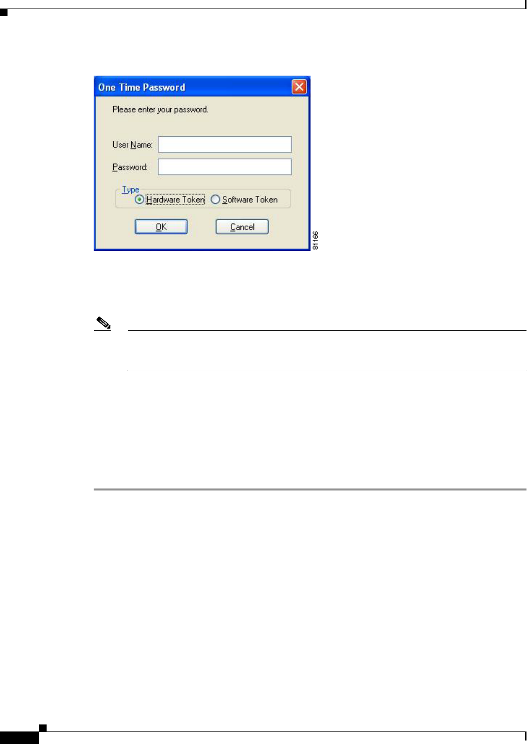
ALPHA DRAFT - CISCO CONFIDENTIAL
6-12
Cisco Aironet 802.11a/b/g Wireless LAN Client Adapters (CB21AG and PI21AG) Installation and Configuration Guide OL-4211-01
Chapter 6 Using EAP Authentication
Restarting the Authentication Process
Figure 6-6 One Time Password Screen
Step 5 Enter your PEAP authentication username in the User Name field.
Step 6 Select either the Hardware Token or Software Token option. If you select the Software Token option,
the Password field on the One Time Password screen changes to the PIN field.
Note The Hardware Token and Software Token options are available only if you selected both of them
on the Generic Token Card Properties screen during configuration. Otherwise, only the option
you selected will be available.
Step 7 Enter either your hardware token password or your software token PIN.
Step 8 Click OK. The PEAP Authentication Status screen appears.
If your client adapter authenticates, the screen shows that each stage was successful and then disappears.
ASTU now shows Authenticated, and the Server Based Authentication field on the ADU Current Status
screen shows PEAP.
If the authentication attempt fails, an error message appears. Refer to the “Error Messages” section on
page 10-11 for the necessary action to take.
Restarting the Authentication Process
If your client adapter was unable to authenticate using the specified username and password and you
have exhausted the retry limit (for example, LEAP tries only once to prevent you from being locked out
of the system), the current profile is disabled until you change the username or password, reboot your
computer, or eject and re-insert the client adapter. To force your client adapter to try to reauthenticate
using the username and password of the current profile, select Reauthenticate from ASTU or the Action
drop-down menu in ADU.

CHAPTER
BETA DRAFT - CISCO CONFIDENTIAL
7-1
Cisco Aironet 802.11a/b/g Wireless LAN Client Adapters (CB21AG and PI21AG) Installation and Configuration Guide
OL-4211-01
7
Performing Diagnostics
This chapter explains how to use ADU to perform user-level diagnostics.
The following topics are covered in this chapter:
•Overview of ADU Diagnostic Tools, page 7-2
•Setting Parameters that Affect ADU Diagnostic Tools, page 7-2
•Viewing the Current Status of Your Client Adapter, page 7-4
•Viewing Statistics for Your Client Adapter, page 7-10
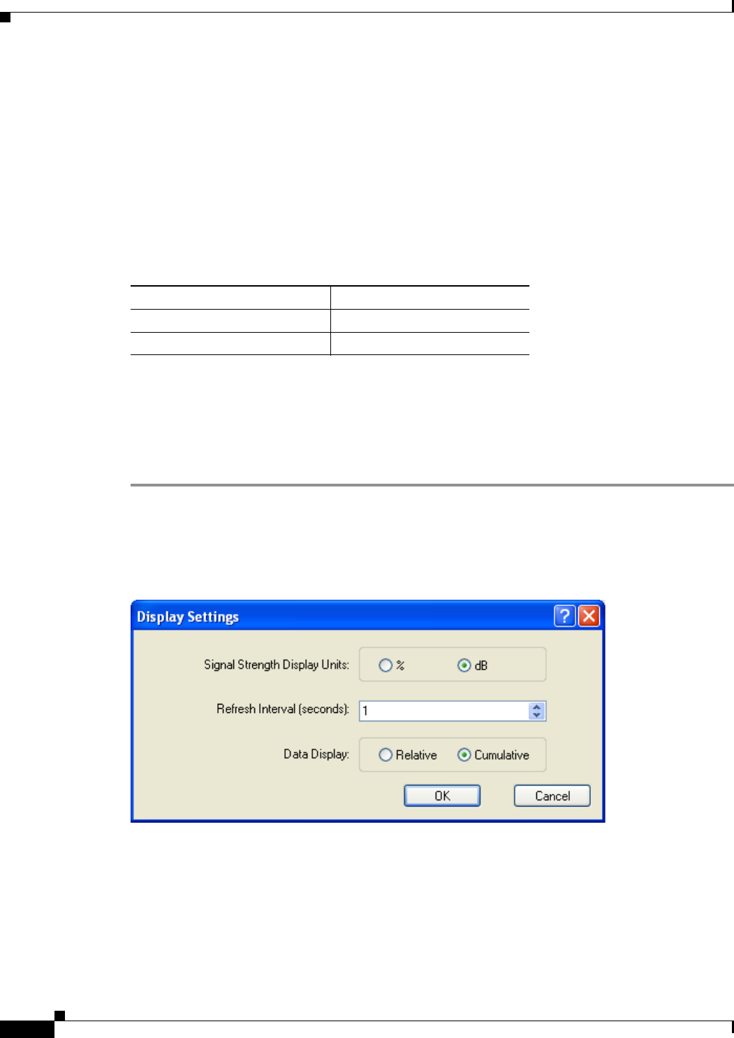
BETA DRAFT - CISCO CONFIDENTIAL
7-2
Cisco Aironet 802.11a/b/g Wireless LAN Client Adapters (CB21AG and PI21AG) Installation and Configuration Guide OL-4211-01
Chapter 7 Performing Diagnostics
Overview of ADU Diagnostic Tools
Overview of ADU Diagnostic Tools
In addition to enabling you to configure your client adapter for use in various types of networks, ADU
provides tools that enable you to assess the performance of the client adapter and other devices on the
wireless network. ADU diagnostic tools perform the following functions:
•Display your client adapter’s current status and configured settings
•Display statistics pertaining to your client adapter’s transmission and reception of data
Table 7-1 enables you to quickly locate instructions for using ADU diagnostic tools.
Setting Parameters that Affect ADU Diagnostic Tools
Several parameters affect the operation of ADU diagnostic tools. Follow the steps below to set these
parameters.
Step 1 Open ADU.
Step 2 Select Display Settings from the Options drop-down menu. The Display Settings screen appears (see
Figure 7-1).
Figure 7-1 Display Settings Screen
Table 7-1 Locating Diagnostic Instructions
Diagnostic Tool Page Number
Status page 7-4
Statistics page 7-10

BETA DRAFT - CISCO CONFIDENTIAL
7-3
Cisco Aironet 802.11a/b/g Wireless LAN Client Adapters (CB21AG and PI21AG) Installation and Configuration Guide
OL-4211-01
Chapter 7 Performing Diagnostics Setting Parameters that Affect ADU Diagnostic Tools
Step 3 Table 7-2 lists and describes the parameters that affect the operation of ADU diagnostic tools. Follow
the instructions in the table to change any parameters.
Step 4 Click OK to save your changes.
Table 7-2 Parameters Affecting ADU Diagnostic Tools
Parameter Description
Signal Strength Display Units Specifies the units used to display signal strength on the status screens.
Default: dB
Units Description
% Displays the signal strength as a
percentage.
dB Displays the signal strength in decibels.
Refresh Interval Specifies how often the status and statistics screens and the ASTU icon
are updated.
Range: 1 to 5 seconds between updates (in 1-second increments)
Default: 5 seconds between updates
Data Display Specifies whether the data that is displayed on the statistics screens
continue to increment until the driver is reloaded or only until an update
occurs (every 1 to 5 seconds).
Options: Relative or Cumulative
Default: Cumulative
Data Display Description
Relative Displays statistical data collected since the
last update, as specified by the Refresh
Interval (1 to 5 seconds).
Cumulative Displays statistical data collected since the
driver was loaded, upon card insertion or
reboot.
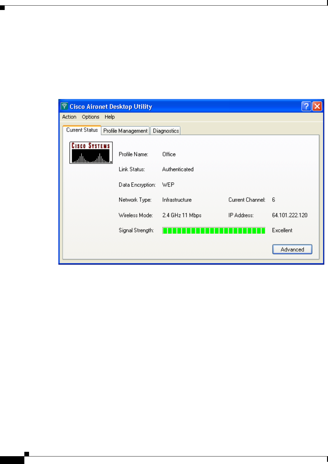
BETA DRAFT - CISCO CONFIDENTIAL
7-4
Cisco Aironet 802.11a/b/g Wireless LAN Client Adapters (CB21AG and PI21AG) Installation and Configuration Guide OL-4211-01
Chapter 7 Performing Diagnostics
Viewing the Current Status of Your Client Adapter
Viewing the Current Status of Your Client Adapter
ADU enables you to view the current status of your client adapter as well as many of the settings that
have been configured for the adapter. To view your client adapter’s status and settings, open ADU. The
Current Status screen appears (see Figure 7-2).
Figure 7-2 Current Status Screen
Table 7-3 interprets each element of the Current Status screen.

BETA DRAFT - CISCO CONFIDENTIAL
7-5
Cisco Aironet 802.11a/b/g Wireless LAN Client Adapters (CB21AG and PI21AG) Installation and Configuration Guide
OL-4211-01
Chapter 7 Performing Diagnostics Viewing the Current Status of Your Client Adapter
Table 7-3 Basic Client Adapter Status
Status Description
Profile Name The network configuration (or profile) your client adapter is currently
using.
Link Status The operational mode of your client adapter.
Value: Not Associated, Associated, Authenticating, Authenticated,
Authentication Failed, Authentication Failed Retrying
Link Status Description
Not Associated The client adapter has not established a
connection to an access point.
Associated The client adapter has established a
connection to an access point.
Authenticating The client adapter is associated to an
access point, and the EAP authentication
process has begun but not yet succeeded.
Authenticated The client adapter is associated to an
access point, and the user is EAP
authenticated.
Authentication Failed The client adapter is associated to an
access point, but the user has failed to EAP
authenticate.
Authentication Failed
Retrying The client adapter is associated to an
access point, the user has failed to EAP
authenticate, but another authentication
attempt is being made.
Data Encryption The data encryption type that was negotiated with the access point upon
association.
Value: None, WEP, CKIP, or TKIP
Network Type The type of network in which your client adapter is being used.
Value: Infrastructure or Ad Hoc
Note Refer to the Network Type parameter in Table 5-3 for
information on setting the network type.
Current Channel The channel that your client adapter is currently using for
communications. This field displays “Scanning” while the client
adapter searches for a channel.
Value: Dependent on radio band and regulatory domain
Note Refer to the Channel parameter in Table 5-3 for information on
selecting the channel for your client adapter.
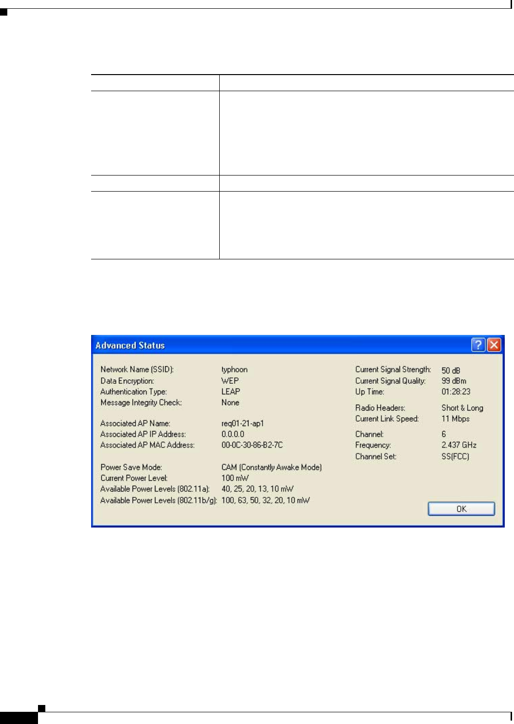
BETA DRAFT - CISCO CONFIDENTIAL
7-6
Cisco Aironet 802.11a/b/g Wireless LAN Client Adapters (CB21AG and PI21AG) Installation and Configuration Guide OL-4211-01
Chapter 7 Performing Diagnostics
Viewing the Current Status of Your Client Adapter
Click Advanced if you want to view more detailed status information for your client adapter. The
Advanced Status screen appears (see Figure 7-3).
Figure 7-3 Advanced Status Screen
Table 7-4 interprets each element of the Advanced Status screen.
Wireless Mode The frequency and rate at which your client adapter is transmitting or
receiving packets to or from access points
Value: 5 GHz 54 Mbps, 2.4 GHz 11 Mbps, or 2.4 GHz 54 Mbps
Note Refer to the Wireless Mode parameter in Table 5-3 for
information on selecting the wireless mode for your client
adapter.
IP Address The IP address of your client adapter.
Signal Strength The signal strength for all received packets. The color of this
parameter’s progress bar provides a visual interpretation of signal
strength.
Value: Excellent (green), Good (green), Fair (orange), Poor (yellow),
or No Link
Table 7-3 Basic Client Adapter Status (continued)
Status Description

BETA DRAFT - CISCO CONFIDENTIAL
7-7
Cisco Aironet 802.11a/b/g Wireless LAN Client Adapters (CB21AG and PI21AG) Installation and Configuration Guide
OL-4211-01
Chapter 7 Performing Diagnostics Viewing the Current Status of Your Client Adapter
Table 7-4 Advanced Client Adapter Status
Status Description
Network Name (SSID) The name of the network to which your client adapter is currently
associated.
Note Refer to the SSID1 parameter in Table 5-2 for information on
setting the client adapter’s SSID.
Data Encryption The data encryption type that was negotiated with the access point upon
association.
Value: None, WEP, CKIP, or TKIP
Authentication Type The EAP authentication type that your client adapter is currently using.
Value: TBD
Note Refer to the “Setting Security Parameters” section on page 5-10
for information on setting the authentication type.
Associated AP Name The name of the access point to which your client adapter is associated.
It is shown only if the client adapter is in infrastructure mode, the
access point was configured with a name, and Aironet Extensions are
enabled (on access points running Cisco IOS release 12.2(4)JA or
greater).
Associated AP IP Address The IP address of the access point to which your client adapter is
associated. It is shown only if the client adapter is in infrastructure
mode, the access point was configured with an IP address, and Aironet
Extensions are enabled (on access points running Cisco IOS release
12.2(4)JA or greater).
Note If Aironet Extensions are disabled, the IP address of the
associated access point is shown as 0.0.0.0.
Associated AP MAC Address The MAC address of the access point to which your client adapter is
associated. It is shown only if the client adapter is in infrastructure
mode.
Note This field displays the MAC address of the access point’s
Ethernet port (for access points that do not run Cisco IOS) or
the MAC address of the access point’s radio (for access points
that run Cisco IOS). The MAC address of the Ethernet port on
access points that run Cisco IOS is printed on a label on the
back of the device.
Power Save Mode The client adapter’s current power consumption setting.
Value: CAM (Constantly Awake Mode), Max PSP (Max Power
Saving), or Fast PSP (Power Save Mode)
Note Refer to the Power Save Mode parameter in Table 5-3 for
information on setting the client adapter’s power save mode.

BETA DRAFT - CISCO CONFIDENTIAL
7-8
Cisco Aironet 802.11a/b/g Wireless LAN Client Adapters (CB21AG and PI21AG) Installation and Configuration Guide OL-4211-01
Chapter 7 Performing Diagnostics
Viewing the Current Status of Your Client Adapter
Current Power Level The power level at which your client adapter is currently transmitting.
The maximum level is dependent upon the radio band used and your
country’s regulatory agency.
Value: 10, 20, 32, 50, 63, or 100 mW (802.11b/g band);
10, 13, 20, 25, or 40 mW (802.11a band)
Note Refer to the Transmit Power Level parameter in Table 5-3 for
information on setting the client adapter’s power level.
Available Power Levels The power levels at which your client adapter is capable of
transmitting. The maximum level is dependent upon the radio band
used and your country’s regulatory agency.
Value: 10, 20, 32, 50, 63, or 100 mW (802.11b/g band);
10, 13, 20, 25, or 40 mW (802.11a band)
Note Refer to the Transmit Power Level parameter in Table 5-3 for
information on the client adapter’s available power levels.
Current Signal Strength The signal strength for all received packets. The higher the value, the
stronger the signal.
Range: 0 to 100%
Current Signal Quality The signal quality for all received packets. The higher the value, the
clearer the signal.
Range: 0 to 100%
Note This setting appears only if you selected signal strength to be
displayed as a percentage. See the Signal Strength Display
Units parameter in Table 7-2 for information.
Up Time The amount of time (in hours:minutes:seconds) since the client adapter
was last reset. If the adapter has been running for more than 24 hours,
the time is displayed in days, hours:minutes:seconds.
802.11b Preamble Indicates whether your client adapter is using only long radio headers
or short and long radio headers.
Value: Short & Long or Long Only
Note This field contains a value only when the client adapter is
operated in 2.4-GHz 11-Mbps or 2.4-GHz 54-Mbps mode.
Note Refer to the 802.11b Preamble parameter in Table 5-3 for
information on using radio headers.
Table 7-4 Advanced Client Adapter Status (continued)
Status Description

BETA DRAFT - CISCO CONFIDENTIAL
7-9
Cisco Aironet 802.11a/b/g Wireless LAN Client Adapters (CB21AG and PI21AG) Installation and Configuration Guide
OL-4211-01
Chapter 7 Performing Diagnostics Viewing the Current Status of Your Client Adapter
Click OK to close the Advanced Status screen.
Message Integrity Check Indicates whether your client adapter is using message integrity check
(MIC) to protect packets sent to and received from the access point.
MIC prevents bit-flip attacks on encrypted packets. During a bit-flip
attack, an intruder intercepts an encrypted message, alters it slightly,
and retransmits it, and the receiver accepts the retransmitted message
as legitimate.
Note MIC is supported automatically by the client adapter’s driver,
but it must be enabled on the access point.
Value: None, MMH, or Michael
Message Integrity Check Description
None MIC is disabled.
MMH MIC is enabled and is being used with
CKIP.
Michael MIC is enabled and is being used with
WPA and TKIP.
Current Link Speed The rate at which your client adapter is currently transmitting data
packets.
Value: 1, 2, 5.5, 6, 9, 11, 12, 18, 24, 36, 48, or 54 Mbps
Channel The channel that your client adapter is currently using for
communications. This field displays “Scanning” while the client
adapter searches for a channel.
Value: Dependent on radio band and regulatory domain
Note Refer to the Channel parameter in Table 5-3 for information on
selecting the channel for your client adapter.
Note Refer to Appendix D for a list of channel identifiers, channel
center frequencies, and regulatory domains for each channel.
Frequency The radio frequency that your client adapter is currently using for
communications. This field displays “Scanning” while the client
adapter searches for a frequency.
Value: Dependent on radio band and regulatory domain
Note Refer to the Wireless Mode parameter in Table 5-3 for
information on selecting the frequency for your client adapter.
Channel Set The regulatory domain for which your client adapter is currently
configured. This value is not user selectable.
Value: Americas, AMEA, Japan, or Rest of World
Table 7-4 Advanced Client Adapter Status (continued)
Status Description
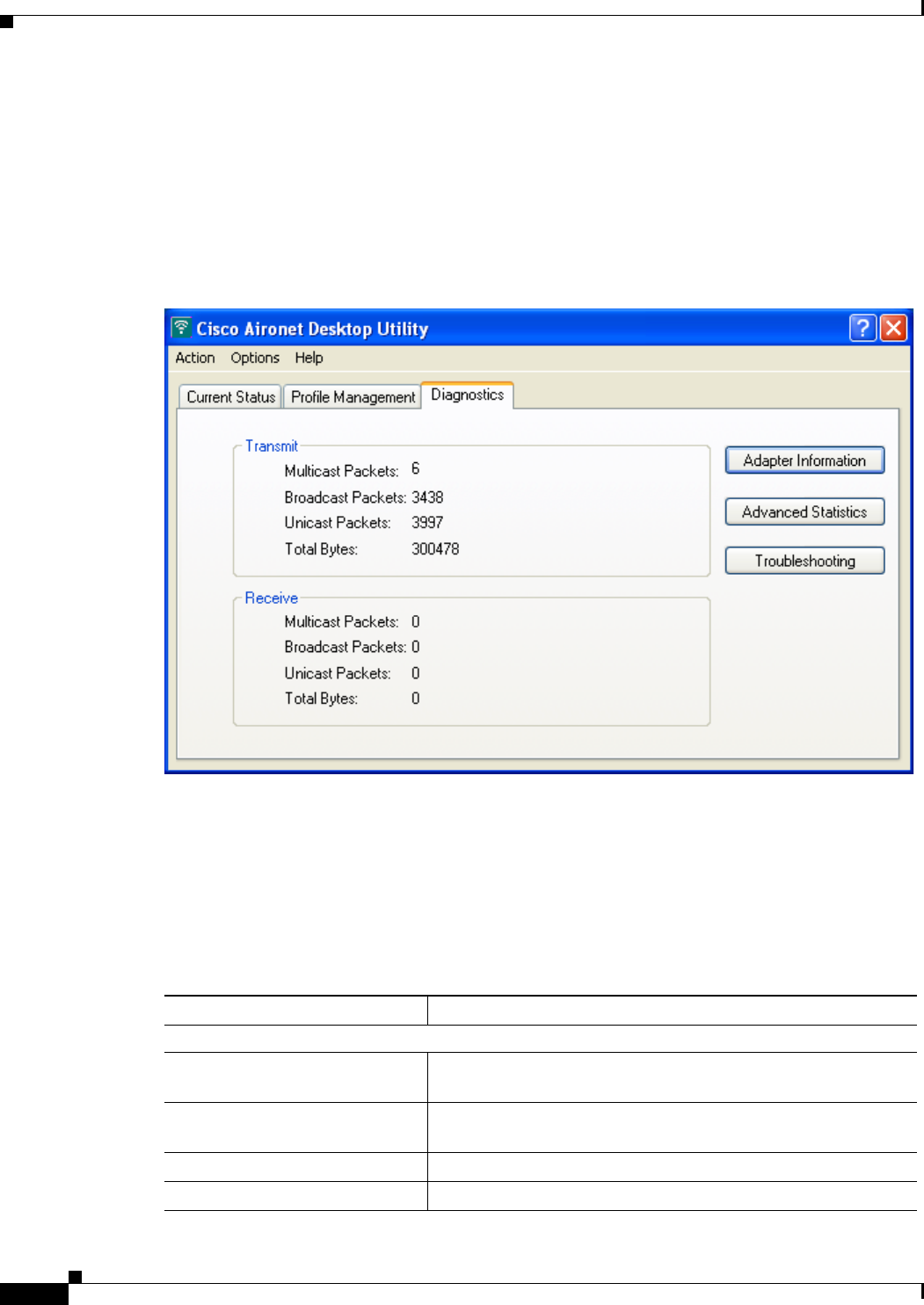
BETA DRAFT - CISCO CONFIDENTIAL
7-10
Cisco Aironet 802.11a/b/g Wireless LAN Client Adapters (CB21AG and PI21AG) Installation and Configuration Guide OL-4211-01
Chapter 7 Performing Diagnostics
Viewing Statistics for Your Client Adapter
Viewing Statistics for Your Client Adapter
ADU enables you to view statistics that indicate how data is being received and transmitted by your
client adapter.
To view your client adapter’s statistics, open ADU; then click the Diagnostics tab. The Cisco Aironet
Desktop Utility (Diagnostics) screen appears (see Figure 7-4).
Figure 7-4 Cisco Aironet Desktop Utility (Diagnostics) Screen
This screen displays basic transmit and receive statistics for your client adapter. The statistics are
calculated on a relative or cumulative basis as specified by the Data Display parameter and are
continually updated at the rate specified by the Refresh Interval parameter. Instructions for changing the
Data Display and Refresh Interval settings are provided in Table 7-2.
Table 7-5 describes each statistic that is displayed for your client adapter.
Table 7-5 Basic Client Adapter Statistics
Statistic Description
Transmit Statistics
Multicast Packets The number of multicast packets that were transmitted
successfully.
Broadcast Packets The number of broadcast packets that were transmitted
successfully.
Unicast Packets The number of unicast packets that were transmitted successfully.
Total Bytes The number of bytes of data that were transmitted successfully.
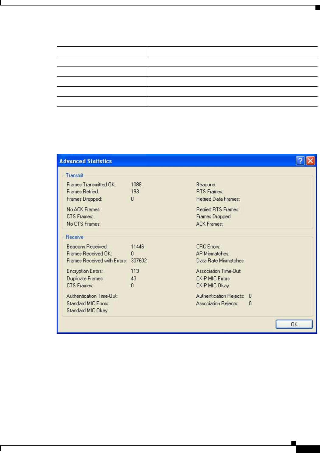
BETA DRAFT - CISCO CONFIDENTIAL
7-11
Cisco Aironet 802.11a/b/g Wireless LAN Client Adapters (CB21AG and PI21AG) Installation and Configuration Guide
OL-4211-01
Chapter 7 Performing Diagnostics Viewing Statistics for Your Client Adapter
Click Advanced Statistics if you want to view additional statistics for your client adapter. The
Advanced Statistics screen appears (see Figure 7-5).
Figure 7-5 Advanced Statistics Screen
Table 7-6 interprets each element of the Advanced Statistics screen.
Receive Statistics
Multicast Packets The number of multicast packets that were received successfully.
Broadcast Packets The number of broadcast packets that were received successfully.
Unicast Packets The number of unicast packets that were received successfully.
Total Bytes The number of bytes of data that were received successfully.
Table 7-5 Basic Client Adapter Statistics (continued)
Statistic Description

BETA DRAFT - CISCO CONFIDENTIAL
7-12
Cisco Aironet 802.11a/b/g Wireless LAN Client Adapters (CB21AG and PI21AG) Installation and Configuration Guide OL-4211-01
Chapter 7 Performing Diagnostics
Viewing Statistics for Your Client Adapter
Table 7-6 Advanced Client Adapter Statistics
Status Description
Transmit Statistics
Frames Transmitted OK The number of frames that were transmitted successfully.
Frames Retried The number of frames that were retried.
Frames Dropped The number of frames that were dropped due to errors or collisions.
No ACK Frames The number of transmitted frames that did not have their corresponding
Ack frame received successfully.
CTS Frames The number of clear-to-send (CTS) frames that were transmitted in
response to a successfully received RTS frame.
No CTS Frames The number of frames for which no CTS frame was received in
response to an RTS frame.
Beacons The number of beacon frames that were transmitted successfully (in ad
hoc mode only).
RTS Frames The number of request-to-send (RTS) frames that were transmitted
successfully.
Retried Data Frames The number of normal data frames that were retransmitted.
Retried RTS Frames The number of request-to-send (RTS) frames that were retransmitted.
Frames Dropped The number of frames that failed to be transmitted successfully after
exhausting the maximum number of retries.
ACK Frames The number of transmitted frames that had their corresponding Ack
frame received successfully.
Receive Statistics
Beacons Received The number of beacon frames that were received successfully.
Frames Received OK The number of all frames that were received successfully.
Frames Received with Errors The number of frames that were received with an invalid checksum.
Encryption Errors The number of frames that were received with encryption errors.
Duplicate Frames The number of duplicate frames that were received successfully.
CTS Frames The number of clear-to-send (CTS) frames that were received in
response to an RTS frame.
Authentication Time-Out The number of times the client adapter tried to authenticate to an access
point but was unable to because the access point did not respond fast
enough (timed out).
Standard MIC Errors The number of frames that were discarded due to an incorrect message
integrity check (MIC) value.
Standard MIC Okay The number of frames that were received with the correct message
integrity check (MIC) value.
CRC Errors The number of cyclic redundancy check (CRC) errors detected in the
data portion of the frame.

BETA DRAFT - CISCO CONFIDENTIAL
7-13
Cisco Aironet 802.11a/b/g Wireless LAN Client Adapters (CB21AG and PI21AG) Installation and Configuration Guide
OL-4211-01
Chapter 7 Performing Diagnostics Viewing Statistics for Your Client Adapter
Click OK to close the Advanced Statistics screen.
AP Mismatches The number of times the client adapter tried to associate to an access
point but was unable to because the access point was not the adapter’s
specified access point.
Note Refer to the Specified Access Point 1- 4 parameter on page 5-10
for information on specifying access points.
Data Rate Mismatches The number of times the client adapter tried to associate to an access
point but was unable to because the adapter’s data rate was not
supported by the access point.
Note Refer to the Wireless Mode parameter in Table 5-3 for
information on supported data rates.
Association Time-Out The number of times the client adapter tried to associate to an access
point but was unable to because the access point did not respond fast
enough (timed out).
CKIP MIC Errors The number of frames that were discarded due to an incorrect message
integrity check (MIC) value when CKIP was being used.
Note This field is displayed only if MIC is enabled on the access
point.
CKIP MIC Okay The number of frames that were received with the correct message
integrity check (MIC) value when CKIP was being used.
Note This field is displayed only if MIC is enabled on the access
point.
Authentication Rejects The number of times the client adapter tried to authenticate to an access
point but was rejected.
Association Rejects The number of times the client adapter tried to associate to an access
point but was rejected.
Table 7-6 Advanced Client Adapter Statistics (continued)
Status Description

BETA DRAFT - CISCO CONFIDENTIAL
7-14
Cisco Aironet 802.11a/b/g Wireless LAN Client Adapters (CB21AG and PI21AG) Installation and Configuration Guide OL-4211-01
Chapter 7 Performing Diagnostics
Viewing Statistics for Your Client Adapter

CHAPTER
BETA DRAFT - CISCO CONFIDENTIAL
8-1
Cisco Aironet 802.11a/b/g Wireless LAN Client Adapters (CB21AG and PI21AG) Installation and Configuration Guide
OL-4211-01
8
Using the Aironet System Tray Utility (ASTU)
This chapter explains how to use the Aironet System Tray Utility (ASTU) to access status information
about your client adapter and perform basic tasks.
The following topics are covered in this chapter:
•Overview of ASTU, page 8-2
•The ASTU Icon, page 8-2
•Tool Tip Window, page 8-3
•Pop-Up Menu, page 8-5
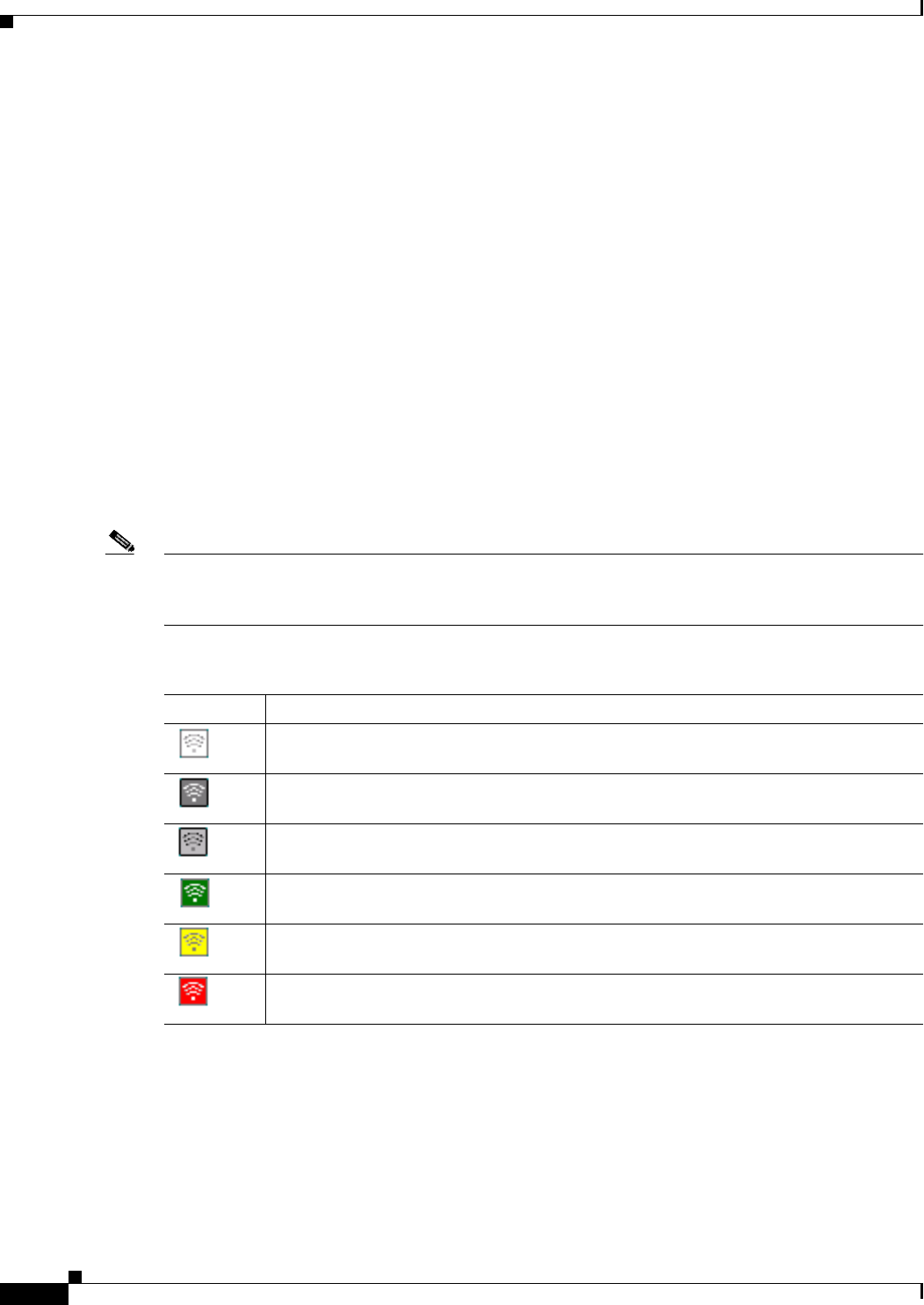
BETA DRAFT - CISCO CONFIDENTIAL
8-2
Cisco Aironet 802.11a/b/g Wireless LAN Client Adapters (CB21AG and PI21AG) Installation and Configuration Guide OL-4211-01
Chapter 8 Using the Aironet System Tray Utility (ASTU)
Overview of ASTU
Overview of ASTU
ASTU is an optional application that provides a small subset of the features available through ADU.
Specifically, it enables you to access status information about your client adapter and perform basic
tasks. ASTU is accessible from an icon in the Windows system tray, making it easily accessible and
convenient to use. The ASTU icon appears only if a client adapter is installed in your computer.
ASTU provides information and options in the following ways:
•In the appearance of the icon itself
•Through a tool tip window that appears when you hover the cursor over the icon
•Through a pop-up menu that appears when you right-click the icon
The ASTU Icon
The appearance of the ASTU icon indicates the connection status of your client adapter. ASTU reads the
client adapter status and updates every 1 to 5 seconds, depending on the value entered for the Refresh
Interval on the Display Settings screen. Table 8-1 interprets the different appearances of the ASTU icon.
Note Windows 2000 and XP may display their own wireless network connection status icon in the system tray.
Cisco recommends that you turn off the Windows icon and use the ASTU icon to monitor your wireless
connection.
Table 8-1 Interpreting the ASTU Icon
Icon Description
The client adapter’s radio is turned off.
The client adapter is not associated to an access point.
The client adapter is associated to an access point, but the user is not authenticated.
The client adapter is associated to an access point, and the link quality is excellent or
good.
The client adapter is associated to an access point, and the link quality is fair.
The client adapter is associated to an access point, and the link quality is poor.
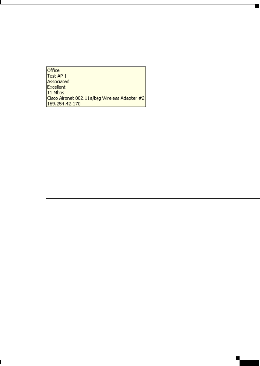
BETA DRAFT - CISCO CONFIDENTIAL
8-3
Cisco Aironet 802.11a/b/g Wireless LAN Client Adapters (CB21AG and PI21AG) Installation and Configuration Guide
OL-4211-01
Chapter 8 Using the Aironet System Tray Utility (ASTU) Tool Tip Window
Tool Tip Window
When you hover the cursor over the ASTU icon, the Tool Tip window appears (see Figure 8-1).
Figure 8-1 Tool Tip Window
This window provides information on the current status of your client adapter. Table 8-2 lists and
describes each element of the Tool Tip window.
Table 8-2 Tool Tip Window Elements
Status Element Description
Active profile The network configuration (or profile) that your client adapter is
currently using.
SSID The name of the network to which your client adapter is currently
associated.
Note Refer to the SSID1 parameter in Table 5-2 for information on
setting the client adapter's SSID.

BETA DRAFT - CISCO CONFIDENTIAL
8-4
Cisco Aironet 802.11a/b/g Wireless LAN Client Adapters (CB21AG and PI21AG) Installation and Configuration Guide OL-4211-01
Chapter 8 Using the Aironet System Tray Utility (ASTU)
Tool Tip Window
Connection status The operational mode of your client adapter.
Value: Not Associated, Associated, Authenticating, Authenticated,
Authentication Failed, Authentication Failed Retrying
Connection Status Description
Not Associated The client adapter has not established a
connection to an access point.
Associated The client adapter has established a
connection to an access point.
Authenticating The client adapter is associated to an
access point, and the EAP authentication
process has begun but not yet succeeded.
Authenticated The client adapter is associated to an
access point, and the user is EAP
authenticated.
Authentication Failed The client adapter is associated to an
access point, but the user has failed to EAP
authenticate.
Authentication Failed
Retrying The client adapter is associated to an
access point, the user has failed to EAP
authenticate, but another authentication
attempt is being made.
Link quality The client adapter's ability to communicate with the access point,
which is determined by the combined result of the adapter's signal
strength and signal quality.
Value: Excellent, Good, Fair, Poor, or No Link
Link speed The rate at which your client adapter is currently transmitting data
packets.
Value: 1, 2, 5.5, 6, 9, 11, 12, 18, 24, 36, 48, or 54 Mbps
Client adapter type A description of your client adapter.
Client adapter IP address The IP address of your client adapter.
Table 8-2 Tool Tip Window Elements (continued)
Status Element Description
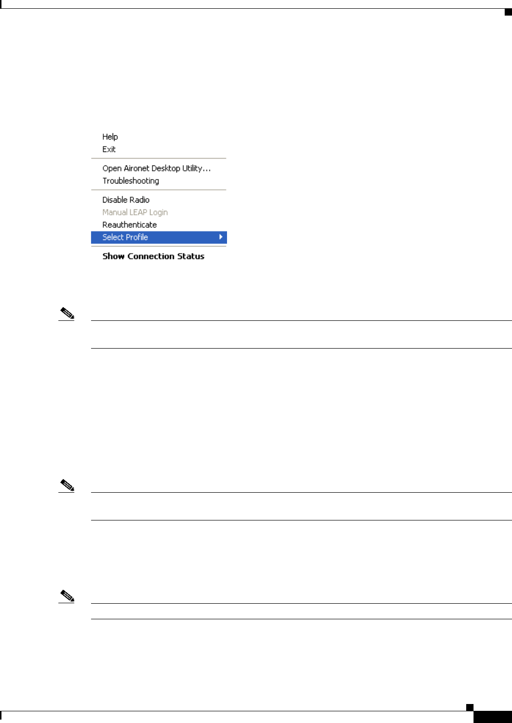
BETA DRAFT - CISCO CONFIDENTIAL
8-5
Cisco Aironet 802.11a/b/g Wireless LAN Client Adapters (CB21AG and PI21AG) Installation and Configuration Guide
OL-4211-01
Chapter 8 Using the Aironet System Tray Utility (ASTU) Pop-Up Menu
Pop-Up Menu
When you right-click the ASTU icon, the ASTU pop-up menu appears (see Figure 8-2).
Figure 8-2 ASTU Pop-Up Menu
The following sections describe each ASTU pop-up menu option.
Note If your system administrator used an administrative tool to deactivate certain ASTU menu options, these
options do not appear in the menu and therefore cannot be selected.
Help
This option enables you to access the online help.
Exit
This option closes ADU and ASTU.
Note To reactivate ADU, double-click the Aironet Desktop Utility icon on your computer desktop. To
reactivate ASTU, select the Enable Tray Icon option from ADU’s Action drop-down menu.
Open Aironet Desktop Utility
This option activates ADU. It is available only if ADU was installed.
Note You can also activate ADU by double-clicking the ASTU icon.

BETA DRAFT - CISCO CONFIDENTIAL
8-6
Cisco Aironet 802.11a/b/g Wireless LAN Client Adapters (CB21AG and PI21AG) Installation and Configuration Guide OL-4211-01
Chapter 8 Using the Aironet System Tray Utility (ASTU)
Pop-Up Menu
Troubleshooting
This option activates the troubleshooting utility, which enables you to identify and resolve configuration
and association problems with your client adapter. Refer to the “Using the Troubleshooting Utility”
section on page 10-3 for detailed instructions on using this utility.
Preferences
When you select this option, the Aironet System Tray Utility Preferences screen appears (see
Figure 8-3).
Figure 8-3 Aironet System Tray Utility Preferences Screen
This screen enables you to determine when ASTU runs and to select the options that appear on the ASTU
pop-up menu. Follow the steps below to make your selections.
Step 1 If you want ASTU to run automatically when Windows starts, make sure the Run the program
automatically when Windows starts check box is checked. Otherwise, uncheck this check box.
Note If you do not select this option and later want to run ASTU, you must use Windows Explorer to
find the path where the ASTU software is installed. (The default location is C:\Program
Files\Cisco Systems\Aironet Client Monitor.) Then double-click ACUMon.exe.

BETA DRAFT - CISCO CONFIDENTIAL
8-7
Cisco Aironet 802.11a/b/g Wireless LAN Client Adapters (CB21AG and PI21AG) Installation and Configuration Guide
OL-4211-01
Chapter 8 Using the Aironet System Tray Utility (ASTU) Pop-Up Menu
Step 2 In the Menu Options portion of the screen, make sure the check boxes of all the options that you want
to appear in the ASTU pop-up menu are checked. Any options that are not checked will not be included
in the menu.
Note The Preferences option cannot be deselected. It always appears in the ASTU pop-up menu.
Step 3 Click OK to save your changes.
Enable/Disable Radio
This option enables you to turn the client adapter’s radio on or off. Turning the radio off prevents the
adapter from transmitting RF energy. You might want to turn off the client adapter’s radio in the
following situations:
•You are not transmitting data and want to conserve battery power.
•You are using a laptop on an airplane and want to prevent the adapter’s transmissions from
potentially interfering with the operation of certain devices.
When the radio is on, it periodically sends out probes even if it is not associated to an access point, as
required by the 802.11 specification. Therefore, it is important to turn it off around devices that are
susceptible to RF interference.
Note Your client adapter is not associated while the radio is off.
Note If your client adapter’s radio is turned off before your computer enters standby or hibernate mode or
before you reboot the computer, the radio remains off when the computer resumes. You must turn the
radio back on to resume operation.
If the radio is on, select Disable Radio to turn off the radio.
If the radio is off, select Enable Radio to turn on the radio.
Manual LEAP Login
TBD
Reauthenticate
This option enables you to force your client adapter to try to reauthenticate using the username and
password of the current profile.
If your client adapter was unable to authenticate using the specified username and password and you
have exhausted the retry limit (for example, LEAP tries only once to prevent you from being locked out
of the system), the current profile is disabled until you change the username or password, reboot your
computer, eject and reinsert the client adapter, or select the Reauthenticate option.
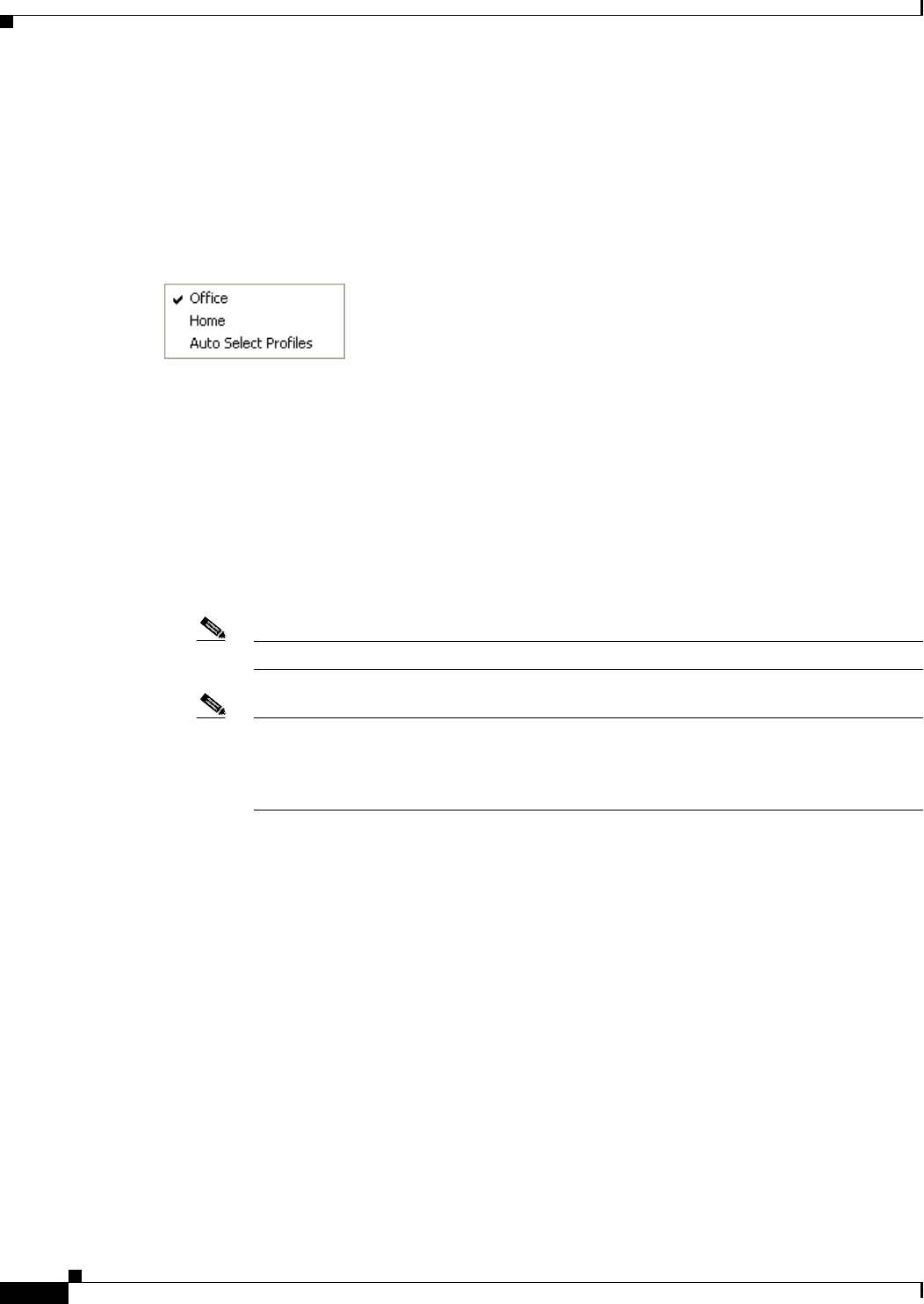
BETA DRAFT - CISCO CONFIDENTIAL
8-8
Cisco Aironet 802.11a/b/g Wireless LAN Client Adapters (CB21AG and PI21AG) Installation and Configuration Guide OL-4211-01
Chapter 8 Using the Aironet System Tray Utility (ASTU)
Pop-Up Menu
Select Profile
This option enables you to select the active profile for your client adapter.
When you select Select Profile from the ASTU pop-up menu, a profiles submenu appears (see
Figure 8-4).
Figure 8-4 Profiles Submenu
From this menu, you can choose between the following options:
•Auto Select Profiles—Causes the client adapter’s driver to automatically select a profile from the
list of profiles that were set up in ACU to be included in auto profile selection.
If the client adapter loses association for more than 10 seconds (or for more than the time specified
by the LEAP authentication timeout value on the LEAP Settings screen if LEAP is enabled), the
driver switches automatically to another profile that is included in auto profile selection. The adapter
will not switch profiles as long as it remains associated or reassociates within 10 seconds (or within
the time specified by the LEAP authentication timeout value). To force the client adapter to associate
to a different access point, you must select a new profile.
Note This option is available only if two or more profiles are included in auto profile selection.
Note Login scripts are not reliable if you use auto profile selection with LEAP. If you LEAP
authenticate and achieve full network connectivity before or at the same time as you log into
the computer, the login scripts will run. However, if you LEAP authenticate and achieve full
network connectivity after you log into the computer, the login scripts will not run.
•A specific profile—When you select a profile from the list of available profiles, the client adapter
attempts to establish a connection to an access point using the parameters that were configured for
that profile.
If the client adapter cannot associate to the access point or loses association while using the selected
profile, the adapter does not attempt to associate using another profile. To associate, you must select
a different profile or select Auto Select Profiles.
Simply click the desired profile to select it. A check mark appears beside the profile, and the client
adapter attempts to establish a connection using the selected profile.
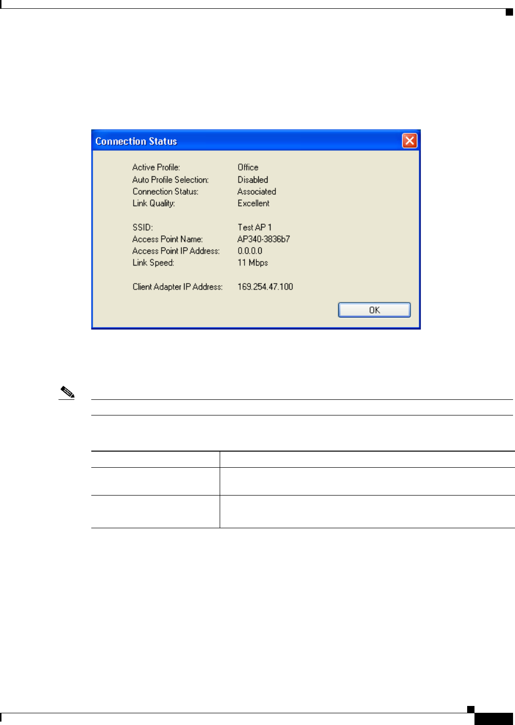
BETA DRAFT - CISCO CONFIDENTIAL
8-9
Cisco Aironet 802.11a/b/g Wireless LAN Client Adapters (CB21AG and PI21AG) Installation and Configuration Guide
OL-4211-01
Chapter 8 Using the Aironet System Tray Utility (ASTU) Pop-Up Menu
Show Connection Status
When you select this option, the Connection Status screen appears (see Figure 8-5).
Figure 8-5 Connection Status Screen
This screen provides information on the current status of your client adapter. Table 8-3 interprets each
element of the Connection Status screen.
Note You can also access the Connection Status screen by double-clicking the ASTU icon.
Table 8-3 Connection Status Screen Elements
Status Element Description
Active Profile The network configuration (or profile) that your client adapter is
currently using.
Auto Profile Selection Indicates whether your client adapter is using auto profile selection.
Value: Enabled or Disabled

BETA DRAFT - CISCO CONFIDENTIAL
8-10
Cisco Aironet 802.11a/b/g Wireless LAN Client Adapters (CB21AG and PI21AG) Installation and Configuration Guide OL-4211-01
Chapter 8 Using the Aironet System Tray Utility (ASTU)
Pop-Up Menu
Connection Status The operational mode of your client adapter.
Value: Not Associated, Associated, Authenticating, Authenticated,
Authentication Failed, Authentication Failed Retrying
Connection Status Description
Not Associated The client adapter has not established a
connection to an access point.
Associated The client adapter has established a
connection to an access point.
Authenticating The client adapter is associated to an
access point, and the EAP authentication
process has begun but not yet succeeded.
Authenticated The client adapter is associated to an
access point, and the user is EAP
authenticated.
Authentication Failed The client adapter is associated to an
access point, but the user has failed to EAP
authenticate.
Authentication Failed
Retrying The client adapter is associated to an
access point, the user has failed to EAP
authenticate, but another authentication
attempt is being made.
Link Quality The client adapter’s ability to communicate with the access point,
which is determined by the combined result of the adapter’s signal
strength and signal quality.
Value: Excellent, Good, Fair, or Poor
SSID The name of the network to which your client adapter is currently
associated.
Note Refer to the SSID1 parameter in Table 5-2 for information on
setting the client adapter’s SSID.
Access Point Name The name of the access point to which your client adapter is associated.
It is shown only if the client adapter is in infrastructure mode, the
access point was configured with a name, and Aironet Extensions are
enabled (on access points running Cisco IOS release 12.2(4)JA or
greater).
Access Point IP Address The IP address of the access point to which your client adapter is
associated. It is shown only if the client adapter is in infrastructure
mode, the access point was configured with an IP address, and Aironet
Extensions are enabled (on access points running Cisco IOS release
12.2(4)JA or greater).
Note If Aironet Extensions are disabled, the IP address of the
associated access point is shown as 0.0.0.0.
Table 8-3 Connection Status Screen Elements (continued)
Status Element Description

BETA DRAFT - CISCO CONFIDENTIAL
8-11
Cisco Aironet 802.11a/b/g Wireless LAN Client Adapters (CB21AG and PI21AG) Installation and Configuration Guide
OL-4211-01
Chapter 8 Using the Aironet System Tray Utility (ASTU) Pop-Up Menu
Link Speed The rate at which your client adapter is currently transmitting data
packets.
Value: 1, 2, 5.5, 6, 9, 11, 12, 18, 24, 36, 48, or 54 Mbps
Client Adapter IP Address The IP address of your client adapter.
Table 8-3 Connection Status Screen Elements (continued)
Status Element Description

BETA DRAFT - CISCO CONFIDENTIAL
8-12
Cisco Aironet 802.11a/b/g Wireless LAN Client Adapters (CB21AG and PI21AG) Installation and Configuration Guide OL-4211-01
Chapter 8 Using the Aironet System Tray Utility (ASTU)
Pop-Up Menu

CHAPTER
BETA DRAFT - CISCO CONFIDENTIAL
9-1
Cisco Aironet 802.11a/b/g Wireless LAN Client Adapters (CB21AG and PI21AG) Installation and Configuration Guide
OL-4211-01
9
Routine Procedures
This chapter provides procedures for common tasks related to the client adapter.
The following topics are covered in this chapter:
•Removing a Client Adapter, page 9-2
•Client Adapter Software Procedures, page 9-3
•Turning Your Client Adapter’s Radio On or Off, page 9-10

BETA DRAFT - CISCO CONFIDENTIAL
9-2
Cisco Aironet 802.11a/b/g Wireless LAN Client Adapters (CB21AG and PI21AG) Installation and Configuration Guide OL-4211-01
Chapter 9 Routine Procedures
Removing a Client Adapter
Removing a Client Adapter
Follow the instructions in this section to remove a PC-Cardbus card or PCI card from a computing
device, when necessary.
Caution These procedures and the physical connections they describe apply generally to conventional Cardbus
slots and PCI expansion slots. In cases of custom or nonconventional equipment, be alert to possible
differences in Cardbus slot and PCI expansion slot configurations.
Removing a PC-Cardbus Card
To remove a PC-Cardbus card after it is successfully installed and configured (such as when your laptop
is to be transported), completely shut down your computer and pull the card directly out of the Cardbus
slot. When the card is reinserted and the computer is rebooted, your connection to the network should
be re-established.
Note If you need to remove your PC-Cardbus card but do not want to shut down your computer, double-click
the Unplug or Eject Hardware icon in the Windows system tray, select the Cisco Aironet client adapter
you want to remove under Hardware devices, click Stop, and click OK twice. Then pull the card directly
out of the card slot.
Removing a PCI Card
Because PCI client adapters are installed inside desktop computers, which are not designed for portable
use, you should have little reason to remove the adapter. However, instructions are provided below in
case you ever need to remove your PCI card.
Step 1 Completely shut down your computer.
Step 2 Remove the computer cover.
Step 3 Remove the screw from the top of the CPU back panel above the PCI expansion slot that holds your client
adapter.
Step 4 Pull up firmly on the client adapter to release it from the slot and carefully tilt the adapter to slip its
antenna through the opening near the slot.
Step 5 Reinstall the screw on the CPU back panel and replace the computer cover.
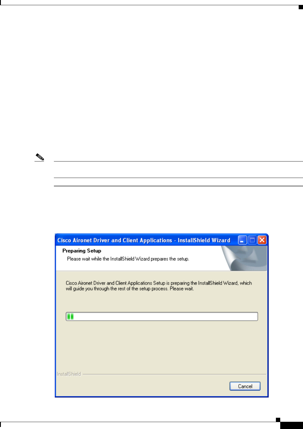
BETA DRAFT - CISCO CONFIDENTIAL
9-3
Cisco Aironet 802.11a/b/g Wireless LAN Client Adapters (CB21AG and PI21AG) Installation and Configuration Guide
OL-4211-01
Chapter 9 Routine Procedures Client Adapter Software Procedures
Client Adapter Software Procedures
This section provides instructions for the following procedures:
•Upgrading the client adapter software, page 9-3
•Uninstalling the client adapter software, page 9-6
•Finding the driver version, page 9-7
•ADU procedures, page 9-7
•ACM procedures, page 9-10
Upgrading the Client Adapter Software
Follow the steps below to upgrade your Cisco Aironet CB21AG or PI21AG client adapter software to a
more recent version using the settings that were selected during the last installation.
Note If you want to upgrade your client adapter software using new settings, uninstall the previous installation
(see the instructions on page 9-6); then install the new software (see the instructions on page 3-8).
Step 1 Use Windows Explorer to find the Install Wizard file.
Step 2 Double-click the file. The “Starting InstallShield Wizard” message appears followed by the Preparing
Setup screen (see Figure 9-1) and the Previous Installation Detected screen (see Figure 9-2).
Figure 9-1 Preparing Setup Screen
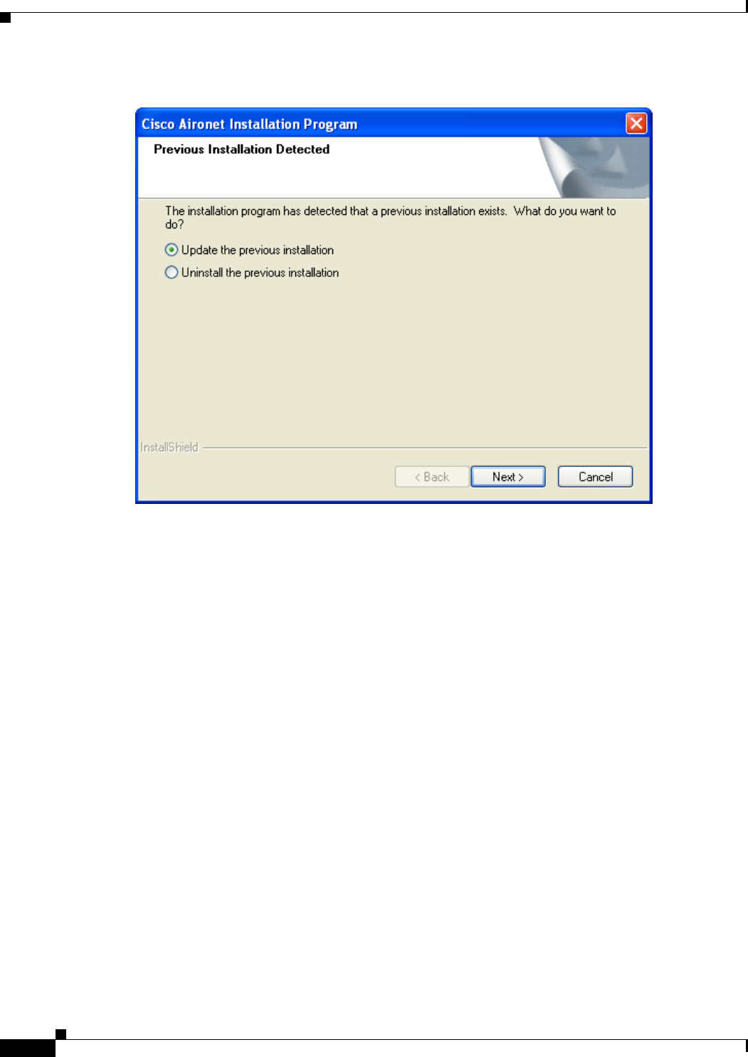
BETA DRAFT - CISCO CONFIDENTIAL
9-4
Cisco Aironet 802.11a/b/g Wireless LAN Client Adapters (CB21AG and PI21AG) Installation and Configuration Guide OL-4211-01
Chapter 9 Routine Procedures
Client Adapter Software Procedures
Figure 9-2 Previous Installation Detected
Step 3 Select Update the previous installation and click Next. The Setup Status screen appears (see
Figure 9-3).

BETA DRAFT - CISCO CONFIDENTIAL
9-5
Cisco Aironet 802.11a/b/g Wireless LAN Client Adapters (CB21AG and PI21AG) Installation and Configuration Guide
OL-4211-01
Chapter 9 Routine Procedures Client Adapter Software Procedures
Figure 9-3 Setup Status Screen
The upgrade process begins, and you are notified as each software component is reinstalled.
Note This process may take several minutes.
Step 4 When the InstallShield Wizard Complete screen appears (see Figure 9-4), select Yes, I want to restart
my computer now and click Finish.

BETA DRAFT - CISCO CONFIDENTIAL
9-6
Cisco Aironet 802.11a/b/g Wireless LAN Client Adapters (CB21AG and PI21AG) Installation and Configuration Guide OL-4211-01
Chapter 9 Routine Procedures
Client Adapter Software Procedures
Figure 9-4 InstallShield Wizard Complete Screen
The client adapter has been upgraded.
Uninstalling the Client Adapter Software
This section provides instructions for uninstalling the software for your Cisco Aironet CB21AG or
PI21AG client adapter. This procedure is necessary if you want to remove installed client adapter
software from your computer or downgrade to previous versions.
Note If you want to downgrade to earlier versions of client adapter software, follow the steps below to
uninstall the current software. Then install the older software.
Note When you uninstall the client adapter software, any existing profiles are removed. If you want to save
your profiles for later use, follow the instructions in Chapter 4 to export your profiles before uninstalling
the software.

BETA DRAFT - CISCO CONFIDENTIAL
9-7
Cisco Aironet 802.11a/b/g Wireless LAN Client Adapters (CB21AG and PI21AG) Installation and Configuration Guide
OL-4211-01
Chapter 9 Routine Procedures Client Adapter Software Procedures
Step 1 Perform one of the following:
•If you want to remove the client adapter from your computer, shut down your computer, remove the
client adapter, and reboot your computer.
•If you want to leave your client adapter inserted in your computer, go to Step 2.
Step 2 Use Windows Explorer to find the Install Wizard file.
Step 3 Double-click the file. The “Starting InstallShield Wizard” message appears followed by the Preparing
Setup screen (see Figure 9-1) and the Previous Installation Detected screen (see Figure 9-2).
Step 4 Select Uninstall the previous installation and click Next.
Step 5 When prompted to confirm your decision, click OK. The process to uninstall the files begins.
Note This process may take several minutes.
Step 6 When prompted to uninstall the device driver, click Yes.
Step 7 When the InstallShield Wizard Complete screen appears (see Figure 9-4), select Yes, I want to restart
my computer now and click Finish.
Step 8 If you did not remove the client adapter from your computer, the Found New Hardware Wizard screen
appears after your computer reboots. Click Cancel.
The client adapter software and its program folder have been uninstalled.
Note This procedure does not remove the Install Wizard file. If you want to remove it from your computer,
find the file using Windows Explorer and delete it.
ADU Procedures
This section provides instructions for the following procedures:
•Opening ADU, page 9-7
•Exiting ADU, page 9-8
•Finding the version of ADU, page 9-8
•Viewing client adapter information, page 9-9
•Accessing online help, page 9-10
Opening ADU
To open ADU, perform one of the following:
•Double-click the Aironet Desktop Utility icon on your desktop.
•Select Aironet Desktop Utility (ADU) from the folder in the Windows Start Menu that you chose
during installation (the default location is Start > Program Files > Cisco Aironet > Aironet
Desktop Utility).
•Right-click the ASTU icon in the Windows system tray and select Open Aironet Desktop Utility.
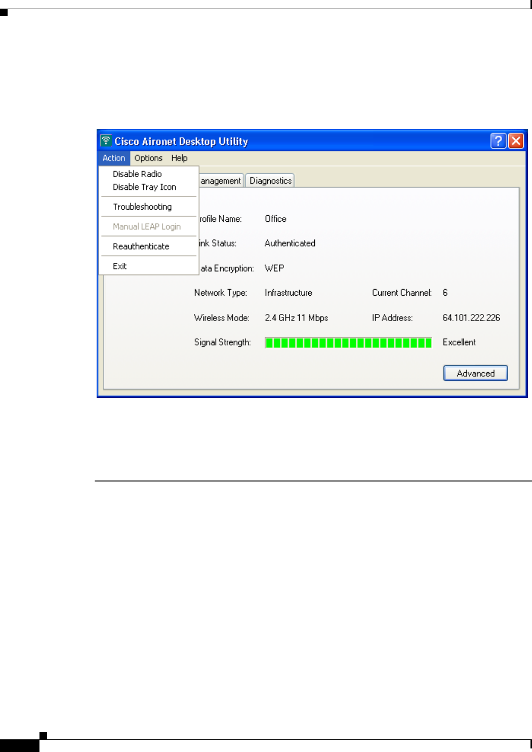
BETA DRAFT - CISCO CONFIDENTIAL
9-8
Cisco Aironet 802.11a/b/g Wireless LAN Client Adapters (CB21AG and PI21AG) Installation and Configuration Guide OL-4211-01
Chapter 9 Routine Procedures
Client Adapter Software Procedures
Exiting ADU
To exit ADU, select Exit from the Action drop-down menu (see Figure 9-5).
Figure 9-5 Action Drop-Down Menu
Finding the Version of ADU
Follow the instructions in this section to find the version of ADU that is currently installed.
Step 1 Open ADU.
Step 2 Select the About Aironet Desktop Utility option from the Help drop-down menu. The About screen
appears (see Figure 9-6).
BETA DRAFT - CISCO CONFIDENTIAL
9-9
Cisco Aironet 802.11a/b/g Wireless LAN Client Adapters (CB21AG and PI21AG) Installation and Configuration Guide
OL-4211-01
Chapter 9 Routine Procedures Client Adapter Software Procedures
Figure 9-6 About Screen
Viewing Client Adapter Information
To view information about your client adapter, open ADU. Then click the Diagnostics tab and Adapter
Information. The Adapter Information screen appears (see Figure 9-7).
Figure 9-7 Adapter Information Screen
Table 9-1 interprets each element of the Adapter Information screen.

BETA DRAFT - CISCO CONFIDENTIAL
9-10
Cisco Aironet 802.11a/b/g Wireless LAN Client Adapters (CB21AG and PI21AG) Installation and Configuration Guide OL-4211-01
Chapter 9 Routine Procedures
Turning Your Client Adapter’s Radio On or Off
Click OK to close the Adapter Information screen.
Accessing Online Help
To access ADU’s online help, open ADU. Then select the Aironet Desktop Utility Help option from
the Help drop-down menu.
ASTU Procedures
Refer to Chapter 8 for instructions on using ASTU.
Turning Your Client Adapter’s Radio On or Off
Your client adapter’s radio can be turned on or off. Turning the radio off prevents the adapter from
transmitting RF energy. You might want to turn off the client adapter’s radio in the following situations:
•You are not transmitting data and want to conserve battery power.
•You are using a laptop on an airplane and want to prevent the adapter’s transmissions from
potentially interfering with the operation of certain devices.
When the radio is on, it periodically sends out probes even if it is not associated to an access point, as
required by the 802.11 specification. Therefore, it is important to turn it off around devices that are
susceptible to RF interference.
Note Your client adapter is not associated while its radio is off.
Table 9-1 Adapter Information
Status Description
Card Name A description of your client adapter.
MAC Address The MAC address assigned to your client adapter at the factory.
Driver The filename and location of your client adapter’s driver.
Driver Version The version of the NDIS device driver that is currently installed on your
computer.
Driver Date The date that your client adapter’s driver was created.
Serial Number The serial number of your client adapter.
Note The serial number appears only if the number has been
programmed into your card.
Manufacturer The manufacturer of your client adapter.
Client Name The name your client adapter uses when it associates to an access point.
Note Refer to the Client Name parameter in Table 5-2 for
information on setting the client name.

BETA DRAFT - CISCO CONFIDENTIAL
9-11
Cisco Aironet 802.11a/b/g Wireless LAN Client Adapters (CB21AG and PI21AG) Installation and Configuration Guide
OL-4211-01
Chapter 9 Routine Procedures Turning Your Client Adapter’s Radio On or Off
Note If your client adapter’s radio is turned off before your computer enters standby or hibernate mode or
before you reboot the computer, the radio remains off when the computer resumes. You must turn the
radio back on to resume operation.
You can use ADU or ASTU to turn the client adapter’s radio on or off. Follow the instructions below to
use ADU or refer to the “Enable/Disable Radio” section on page 8-7 to use ASTU.
If your client adapter’s radio is on, open ADU and select Disable Radio from the Action drop-down
menu (see Figure 9-5) to turn off the radio.
If your client adapter’s radio is off, open ADU and select Enable Radio from the Action drop-down
menu (see Figure 9-5) to turn on the radio.

BETA DRAFT - CISCO CONFIDENTIAL
9-12
Cisco Aironet 802.11a/b/g Wireless LAN Client Adapters (CB21AG and PI21AG) Installation and Configuration Guide OL-4211-01
Chapter 9 Routine Procedures
Turning Your Client Adapter’s Radio On or Off

CHAPTER
BETA DRAFT - CISCO CONFIDENTIAL
10-1
Cisco Aironet 802.11a/b/g Wireless LAN Client Adapters (CB21AG and PI21AG) Installation and Configuration Guide
OL-4211-01
10
Troubleshooting
This chapter provides information for diagnosing and correcting common problems that may be
encountered when installing or operating the client adapter.
The following topics are covered in this chapter:
•Accessing the Latest Troubleshooting Information, page 10-2
•Interpreting the Indicator LEDs, page 10-2
•Troubleshooting the Client Adapter, page 10-3
•Error Messages, page 10-11

BETA DRAFT - CISCO CONFIDENTIAL
10-2
Cisco Aironet 802.11a/b/g Wireless LAN Client Adapters (CB21AG and PI21AG) Installation and Configuration Guide OL-4211-01
Chapter10 Troubleshooting
Accessing the Latest Troubleshooting Information
Accessing the Latest Troubleshooting Information
This chapter provides basic troubleshooting tips for your client adapter. For more up-to-date and
complex troubleshooting information, refer to the TAC web site. To access this site, go to Cisco.com, click
Technical Support > Hardware Support > Wireless Devices. Then select your product and
Troubleshooting to find information on the problem you are experiencing.
Interpreting the Indicator LEDs
The client adapter shows messages and error conditions through its two LEDs:
•Link Integrity/Power LED (green)—This LED lights when the client adapter is receiving power
and blinks slowly when the adapter is linked with the network.
•Link Activity LED (amber)—This LED blinks quickly when the client adapter is receiving or
transmitting data and blinks in a repeating pattern to indicate an error condition.
Table 10-1 interprets the LED operating messages.
Table 10-1 LED Operating Messages
Green LED Amber LED Condition
Off Off Client adapter is not receiving power.
Blinking slowly Off Client adapter is in power save mode.
On Off Client adapter has awakened from power save mode.
Alternating blink: Client adapter is scanning for a network.
On Off
Off On
Blinking slowly Blinking slowly Client adapter is associated to an access point.
Blinking quickly Blinking quickly Client adapter is transmitting or receiving data
while associated to an access point.

BETA DRAFT - CISCO CONFIDENTIAL
10-3
Cisco Aironet 802.11a/b/g Wireless LAN Client Adapters (CB21AG and PI21AG) Installation and Configuration Guide
OL-4211-01
Chapter 10 Troubleshooting Troubleshooting the Client Adapter
Troubleshooting the Client Adapter
This section provides troubleshooting tips should you encounter problems with your client adapter. Use
Table 10-2 to quickly locate specific troubleshooting information.
Using the Troubleshooting Utility
The troubleshooting utility enables you to identify and resolve configuration and association problems
with your client adapter. It is meant to be used only when the client adapter is in infrastructure mode as
it assesses the connection between the adapter and an access point.
Follow the instructions in one of the subsections below to use the utility to diagnosis your client adapter’s
operation, save a detailed report to a text file, or access online help.
Diagnosing Your Client Adapter’s Operation
Step 1 Perform one of the following to activate the troubleshooting utility:
•Open ADU; select Troubleshooting from the Action drop-down menu.
•Open ADU; click the Diagnostics tab and Troubleshooting.
•Right-click the ASTU icon; select Troubleshooting from the pop-up menu.
The Troubleshooting Utility screen appears (see Figure 10-1).
Table 10-2 Locating Troubleshooting Information
Troubleshooting Information Page Number
Using the troubleshooting utility 10-3
Disabling the Microsoft Wireless Configuration
Manager 10-7
Client adapter recognition problems 10-7
Resolving resource conflicts 10-8
Problems associating to an access point 10-9
Problems authenticating to an access point 10-10
Problems connecting to the network 10-10
Prioritizing network connections 10-10
Parameters missing from Profile Manager screen 10-10
Windows Wireless Network Connection icon
shows unavailable connection (Windows XP
only)
10-11
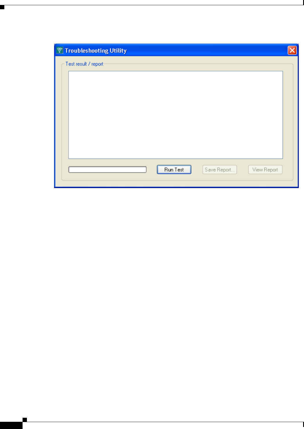
BETA DRAFT - CISCO CONFIDENTIAL
10-4
Cisco Aironet 802.11a/b/g Wireless LAN Client Adapters (CB21AG and PI21AG) Installation and Configuration Guide OL-4211-01
Chapter10 Troubleshooting
Troubleshooting the Client Adapter
Figure 10-1 Troubleshooting Utility Screen
Step 2 Click Run Test. The utility performs the following series of seven tests to check the operation of your
client adapter and to pinpoint specific problems if they exist:
1. Driver installation test
2. Card insertion test
3. Card enable test
4. Radio test
5. Association test
6. Authentication test
7. Network test
The utility runs and then displays the results for each test (see Figure 10-2).
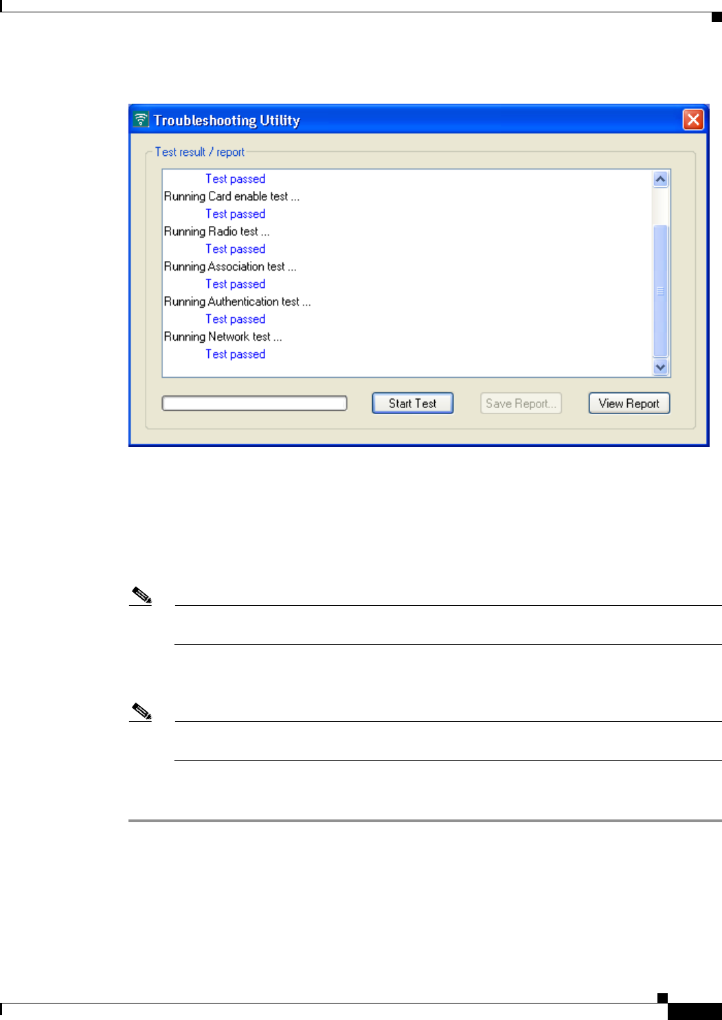
BETA DRAFT - CISCO CONFIDENTIAL
10-5
Cisco Aironet 802.11a/b/g Wireless LAN Client Adapters (CB21AG and PI21AG) Installation and Configuration Guide
OL-4211-01
Chapter 10 Troubleshooting Troubleshooting the Client Adapter
Figure 10-2 Troubleshooting Utility Screen (with Test Results)
One of the following status messages appears for each test:
•Test passed—The test completed successfully.
•Test bypassed—The test was skipped because it was not required for the active profile.
•Test failed—The test failed. Follow the instructions in Step 3 to obtain more details.
Note You can click Stop Test at any time to stop the testing process, or you can click Start Test once
the testing process has stopped to run the test again.
Step 3 To view more detailed information, click View Report. A report appears that provides more detailed
results for your client adapter.
Note The report contains valuable information that, if necessary, could be used by TAC to analyze any
problems. Follow the instructions in the next section if you want to save the report to a text file.
Step 4 If a problem is discovered, the report provides some possible repair suggestions. Follow the repair
instructions carefully and run the troubleshooting utility again.
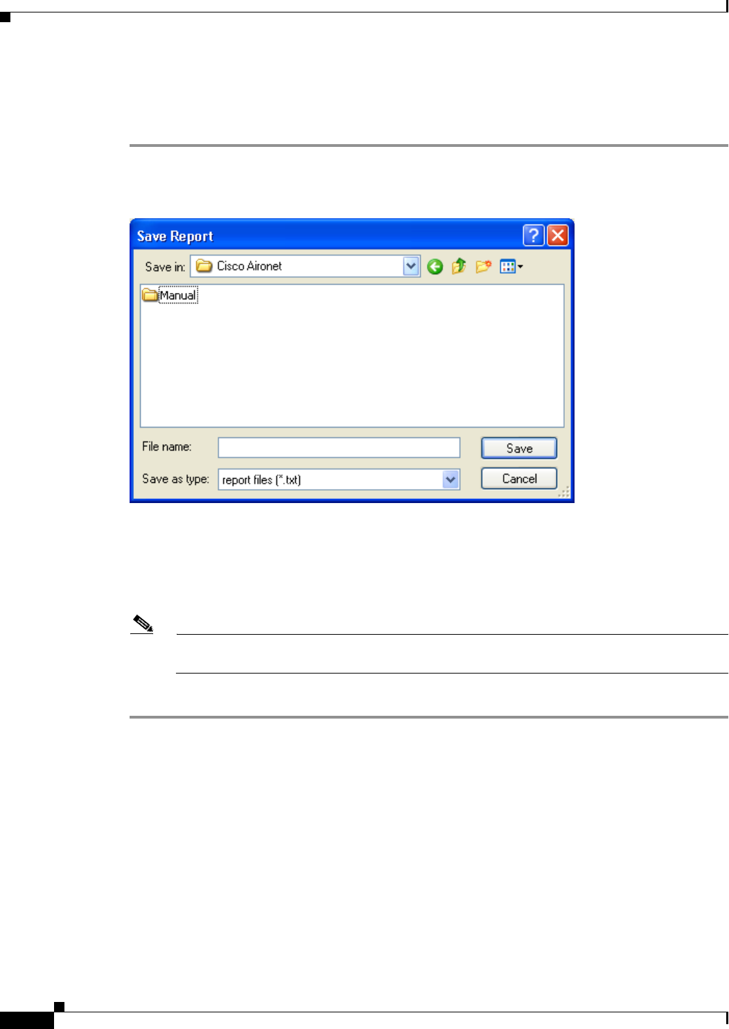
BETA DRAFT - CISCO CONFIDENTIAL
10-6
Cisco Aironet 802.11a/b/g Wireless LAN Client Adapters (CB21AG and PI21AG) Installation and Configuration Guide OL-4211-01
Chapter10 Troubleshooting
Troubleshooting the Client Adapter
Saving the Detailed Report to a Text File
Follow the steps below to save the detailed troubleshooting report to your computer’s hard drive.
Step 1 Click Save Report. The Save Report screen appears (see Figure 10-3).
Figure 10-3 Save Report Screen
Step 2 Enter a name for the detailed report in the File name field. The report is saved as a *.txt file.
Step 3 Use the Save in box at the top of the screen to specify the location on your computer’s hard drive where
the file will be saved.
Note The default location is the Logs folder in the directory where ADU is installed (for example,
C:\Program Files\Cisco Aironet\Logs).
Step 4 Click Save. The file is saved as a text file in the location specified.

BETA DRAFT - CISCO CONFIDENTIAL
10-7
Cisco Aironet 802.11a/b/g Wireless LAN Client Adapters (CB21AG and PI21AG) Installation and Configuration Guide
OL-4211-01
Chapter 10 Troubleshooting Troubleshooting the Client Adapter
Disabling a Cisco Aironet Client Adapter
Cisco Aironet CB21AG and PI21AG client adapter software is incompatible with other Cisco Aironet
client adapter software. Therefore, Cisco recommends that you remove or disable any other Cisco
Aironet adapters before installing or using a CB21AG or PI21AG card.
Follow the steps below to disable a client adapter.
Step 1 Double-click My Computer, Control Panel, and System.
Step 2 Select the Hardware tab.
Step 3 Click Device Manager.
Step 4 Double-click Network adapters.
Step 5 Right-click the client adapter that you want to disable.
Step 6 Select Disable. The client adapter is disabled.
Disabling the Microsoft Wireless Configuration Manager (Windows XP Only)
If any conflicts arise between ADU and the Microsoft Wireless Configuration Manager on a computer
running Windows XP, follow the steps below to disable the Microsoft configuration manager.
Step 1 Double-click My Computer, Control Panel, and Network Connections.
Step 2 Right-click Wireless Network Connection and click Properties.
Step 3 Select the Wireless Networks tab and uncheck the Use Windows to configure my wireless network
settings check box.
Step 4 Select the Authentication tab.
Note In Service Pack 1 for Windows XP, the Authentication tab has moved from its previous location.
To access it, click the Wireless Networks tab, select the network that you are configuring in the
Preferred network list, and click Properties.
Step 5 Uncheck the Enable network access control using IEEE 802.1X check box.
Client Adapter Recognition Problems
If your client adapter is not being recognized by your computer’s PCMCIA adapter, check your
computer’s BIOS and make sure that the PC card controller mode is set to PCIC compatible.
Note A computer’s BIOS varies depending on the manufacturer. For support on BIOS-related issues, consult
your computer’s manufacturer.

BETA DRAFT - CISCO CONFIDENTIAL
10-8
Cisco Aironet 802.11a/b/g Wireless LAN Client Adapters (CB21AG and PI21AG) Installation and Configuration Guide OL-4211-01
Chapter10 Troubleshooting
Troubleshooting the Client Adapter
Resolving Resource Conflicts
If you encounter problems while installing your client adapter on a computer running a Windows
operating system, you may need to specify a different interrupt request (IRQ) or I/O range for the
adapter.
The default IRQ for the client adapter is IRQ 10, which may not work for all systems. Follow the steps
for your specific operating system to obtain an available IRQ.
During installation the adapter’s driver installation script scans for an unused I/O range. The installation
can fail if the I/O range found by the driver installation script is occupied by another device but not
reported by Windows. An I/O range might not be reported if a device is physically present in the system
but not enabled under Windows. Follow the steps for your specific operating system to obtain an
available I/O range.
Resolving Resource Conflicts in Windows 2000
Step 1 Double-click My Computer, Control Panel, and System.
Step 2 Click the Hardware tab and Device Manager.
Step 3 Double-click Network Adapters and the Cisco Systems Wireless LAN Adapter.
Step 4 In the General screen, the Device Status field indicates if a resource problem exists. If a problem is
indicated, click the Resources tab.
Step 5 Uncheck the Use automatic settings check box.
Step 6 Under Resource Settings or Resource Type, click Input/Output Range.
Step 7 Look in the Conflicting Device list at the bottom of the screen. If it indicates that the range is being used
by another device, click the Change Setting button.
Step 8 Scroll through the ranges in the Value dialog box and select one that does not conflict with another
device. The Conflict Information window at the bottom of the screen indicates if the range is already
being used.
Step 9 Click OK.
Step 10 Under Resource Settings or Resource Type, click Interrupt Request.
Step 11 Look in the Conflicting Device list at the bottom of the screen. If it indicates that the IRQ is being used
by another device, click the Change Setting button.
Step 12 Scroll through the IRQs in the Value dialog box and select one that does not conflict with another device.
The Conflict Information window at the bottom of the screen indicates if the IRQ is already being used.
Step 13 Click OK.
Step 14 Reboot your computer.

BETA DRAFT - CISCO CONFIDENTIAL
10-9
Cisco Aironet 802.11a/b/g Wireless LAN Client Adapters (CB21AG and PI21AG) Installation and Configuration Guide
OL-4211-01
Chapter 10 Troubleshooting Troubleshooting the Client Adapter
Resolving Resource Conflicts in Windows XP
Note These instructions assume you are using Windows XP’s classic view, not its category view.
Step 1 Double-click My Computer, Control Panel, and System.
Step 2 Click the Hardware tab and Device Manager.
Step 3 Under Network Adapters, double-click the Cisco Systems Wireless LAN Adapter.
Step 4 In the General screen, the Device Status field indicates if a resource problem exists. If a problem is
indicated, click the Resources tab.
Step 5 Uncheck the Use automatic settings check box.
Step 6 Under Resource Settings, click I/O Range.
Step 7 Look in the Conflicting Device list at the bottom of the screen. If it indicates that the range is being used
by another device, click the Change Setting button.
Step 8 Scroll through the ranges in the Value dialog box and select one that does not conflict with another
device. The Conflict Information window at the bottom of the screen indicates if the range is already
being used.
Step 9 Click OK.
Step 10 Under Resource Settings, click IRQ.
Step 11 Look in the Conflicting Device list at the bottom of the screen. If it indicates that the IRQ is being used
by another device, click the Change Setting button.
Step 12 Scroll through the IRQs in the Value dialog box and select one that does not conflict with another device.
The Conflict Information window at the bottom of the screen indicates if the IRQ is already being used.
Step 13 Click OK.
Step 14 Reboot your computer.
Problems Associating to an Access Point
Follow the instructions below if your client adapter fails to associate to an access point.
•If possible, move your workstation a few feet closer to an access point and try again.
•Make sure that the client adapter is securely inserted in your computer’s client adapter slot.
•If you are using a PCI card, make sure that the antenna is securely attached.
•Make sure that the access point is turned on and operating.
•Check that all parameters are set properly for both the client adapter and the access point. These
include the SSID, EAP authentication, WEP activation, network type, channel, etc.
•Follow the instructions in the previous section to resolve any resource conflicts.
•If the client adapter still fails to establish contact, refer to the “Obtaining Technical Assistance”
section in the Preface for technical support information.

BETA DRAFT - CISCO CONFIDENTIAL
10-10
Cisco Aironet 802.11a/b/g Wireless LAN Client Adapters (CB21AG and PI21AG) Installation and Configuration Guide OL-4211-01
Chapter10 Troubleshooting
Troubleshooting the Client Adapter
Problems Authenticating to an Access Point
If your client adapter is a 40-bit card and LEAP or EAP is enabled, the adapter can associate but not
authenticate to access points using 128-bit encryption. To authenticate to an access point using 128-bit
encryption, you have two options:
•Purchase a 128-bit client adapter. This is the most secure option.
•Disable static WEP for the client adapter and configure the adapter and the access point to associate
to mixed cells. This option presents a security risk because your data is not encrypted as it is sent
over the RF network.
Problems Connecting to the Network
After you have installed the appropriate firmware, driver, client utilities, and security modules, contact
your IS department if you have a problem connecting to the network. Proxy server, network protocols,
and further authentication information might be needed to connect to the network.
Prioritizing Network Connections
If your computer has more than one network adapter is enabled (such as a Cisco Aironet client adapter
and an Ethernet card), you can select which one to use by assigning a priority to your network
connections.
Follow the steps below to prioritize your network connections.
Step 1 Right-click the My Network Places icon on your desktop.
Step 2 Click Properties.
Step 3 Select the Advanced menu option at the top of the screen.
Step 4 Select Advanced Settings. Your network connections are listed in the Connections box on the Adapters
and Bindings tab.
Step 5 Use the arrows beside the Connections box to move the network connection that you want to use to the
top.
Step 6 Click OK.
Parameters Missing from Profile Manager Screen
If some parameters are unavailable on the Profile Manager screen, your system administrator may have
used an administrative tool to deactivate these parameters. In this case, these parameters cannot be
selected.

BETA DRAFT - CISCO CONFIDENTIAL
10-11
Cisco Aironet 802.11a/b/g Wireless LAN Client Adapters (CB21AG and PI21AG) Installation and Configuration Guide
OL-4211-01
Chapter 10 Troubleshooting Error Messages
Windows Wireless Network Connection Icon Shows Unavailable Connection
(Windows XP Only)
If your computer is running Windows XP and you configured your client adapter using ADU, the
Windows Wireless Network Connection icon in the Windows system tray may be marked with a red X
and show an unavailable connection even though a wireless connection exists. This is caused by a
conflict between ADU and Windows XP’s wireless network settings. Simply ignore the Windows icon
and use the ASTU icon to check the status of your client adapter’s wireless connection.
Error Messages
This section provides a list of error messages that may appear during the installation, configuration, or
use of your client adapter. The messages are listed in alphabetical order within each section, and an
explanation as well as a recommended user action are provided for each message.
To Be Added

BETA DRAFT - CISCO CONFIDENTIAL
10-12
Cisco Aironet 802.11a/b/g Wireless LAN Client Adapters (CB21AG and PI21AG) Installation and Configuration Guide OL-4211-01
Chapter10 Troubleshooting
Error Messages

BETA DRAFT - CISCO CONFIDENTIAL
A-1
Cisco Aironet 802.11a/b/g Wireless LAN Client Adapters (CB21AG and PI21AG) Installation and Configuration Guide
OL-4211-01
APPENDIX
A
Technical Specifications
This appendix provides technical specifications for the Cisco Aironet CB21AG and PI21AG Wireless
LAN Client Adapters.
The following topics are covered in this appendix:
•Physical Specifications, page A-2
•Radio Specifications, page A-2
•Power Specifications, page A-5
•Safety and Regulatory Compliance Specifications, page A-6

BETA DRAFT - CISCO CONFIDENTIAL
A-2
Cisco Aironet 802.11a/b/g Wireless LAN Client Adapters (CB21AG and PI21AG) Installation and Configuration Guide OL-4211-01
Appendix A Technical Specifications
Table A-1 lists the technical specifications for the Cisco Aironet CB21AG and PI21AG Wireless LAN
Client Adapters.
Table A-1 Technical Specifications for Cisco Aironet CB21AG and PI21AG Wireless LAN Client
Adapters
Physical Specifications
Size
PC-Cardbus card 4.5 in. L x 2.1 in. W x 0.2 in. H
(11.3 cm L x 5.4 cm W x 0.5 cm H)
PCI card
Standard PCI card 4.7 in. L x 0.7 in. W x 4.8 in. H
(12 cm L x 1.8 cm W x 12.1 cm H)
Low-profile PCI card 4.7 in. L x 0.7 in. W x 3.1 in. H
(12 cm L x 1.8 cm W x 7.9 cm H)
Weight
PC-Cardbus card 1.55 oz (44 g)
PCI card
Standard PCI card
with antenna 3.6 oz (103 g)
Standard PCI card
without antenna 1.9 oz (55 g)
Low-profile PCI card
with antenna 3.5 oz (98 g)
Low-profile PCI card
without antenna 1.7 oz (49 g)
Enclosure
PC-Cardbus card Type II Cardbus
PCI card Standard or low-profile Type II PCI
Connector
PC-Cardbus card 68-pin Cardbus
PCI card 62-pin PCI
Status indicators Green and amber LEDs; see Chapter 10
Operating temperature 32oF to 158oF (0oC to 70oC)
Storage temperature 32oF to 185oF (0oC to 85oC)
Humidity (non-operational) 90% relative humidity
ESD 15 kV (human body model)
Radio Specifications
Type
802.11a Orthogonal frequency division multiplexing (OFDM)
802.11b/g Direct-sequence spread spectrum (DSSS) and orthogonal frequency
division multiplexing (OFDM)

BETA DRAFT - CISCO CONFIDENTIAL
A-3
Cisco Aironet 802.11a/b/g Wireless LAN Client Adapters (CB21AG and PI21AG) Installation and Configuration Guide
OL-4211-01
Appendix A Technical Specifications
Power output
Note Refer to Appendix D for limitations on radiated power (EIRP) levels in the European
community and other countries.
802.11a 40 mW (16 dBm)
25 mW (14 dBm)
20 mW (13 dBm)
13 mW (11 dBm)
10 mW (10 dBm)
802.11b/g 100 mW (20 dBm)
63 mW (18 dBm)
50 mW (17 dBm)
32 mW (15 dBm)
20 mW (13 dBm)
10 mW (10 dBm)
Operating frequency
802.11a 5.15 to 5.25 GHz in the UNII 1 band*
5.25 to 5.35 GHz in the UNII 2 band*
5.470 to 5.725 GHz in the European band
5.725 to 5.825 GHz in the UNII 3 band*
*Depending on the regulatory domain in which the client adapter is
used
802.11b/g 2.400 to 2.497 GHz (depending on the regulatory domain in which the
client adapter is used)
Usable channels
802.11a 5150 to 5350 MHz and 5725 to 5825 MHz
802.11b/g 2412 to 2484 MHz in 5-MHz increments
Interference rejection
802.11a/g 16 dBc @ 6 Mbps adjacent channel rejection
15 dBc @ 9 Mbps adjacent channel rejection
13 dBc @ 12 Mbps adjacent channel rejection
11 dBc @ 18 Mbps adjacent channel rejection
8 dBc @ 24 Mbps adjacent channel rejection
4 dBc @ 36 Mbps adjacent channel rejection
0 dBc @ 48 Mbps adjacent channel rejection
–1 dBc @ 54 Mbps adjacent channel rejection
802.11b 35 dBc adjacent channel rejection
Data rates 1, 2, 5.5, 6, 9, 11, 12, 18, 24, 36, 48, and 54 Mbps
Modulation Differential binary phase shift keying (DBPSK) - 1 Mbps
Differential quaternary phase shift keying (DQPSK) - 2 Mbps
Complementary code keying (CCK) - 5.5 and 11 Mbps
Binary phase shift keying (BPSK) - 6 and 9 Mbps
Quaternary phase shift keying (QPSK) - 12 and 18 Mbps
16-quadrate amplitude modulation (16-QAM) - 24 and 36 Mbps
64-quadrate amplitude modulation (64-QAM) - 48 and 54 Mbps
Table A-1 Technical Specifications for Cisco Aironet CB21AG and PI21AG Wireless LAN Client
Adapters (continued)

BETA DRAFT - CISCO CONFIDENTIAL
A-4
Cisco Aironet 802.11a/b/g Wireless LAN Client Adapters (CB21AG and PI21AG) Installation and Configuration Guide OL-4211-01
Appendix A Technical Specifications
Receiver sensitivity
802.11a 5150 to 5250 MHz
–87 dBm @ 6, 9, 12, and 18 Mbps
–82 dBm @ 24 Mbps
–79 dBm @ 36 Mbps
–74 dBm @ 48 Mbps
–72 dBm @ 54 Mbps
5250 to 5350 MHz
–89 dBm @ 6, 9, and 12 Mbps
–85 dBm @ 18 Mbps
–82 dBm @ 24 Mbps
–79 dBm @ 36 Mbps
–74 dBm @ 48 Mbps
–72 dBm @ 54 Mbps
5470 to 5725 MHz
–87 dBm @ 6, 9, 12, and 18 Mbps
–82 dBm @ 24 Mbps
–79 dBm @ 36 Mbps
–74 dBm @ 48 Mbps
–72 dBm @ 54 Mbps
5725 to 5805 MHz
–84 dBm @ 6, 9, and 12 Mbps
–83 dBm @ 18 Mbps
–82 dBm @ 24 Mbps
–79 dBm @ 36 Mbps
–72 dBm @ 48 Mbps
–65 dBm @ 54 Mbps
802.11b/g –94 dBm @ 1 Mbps
–93 dBm @ 2 Mbps
–92 dBm @ 5.5 Mbps
–90 dBm @ 11 Mbps
–86 dBm @ 6, 9, 12, and 18 Mbps
–84 dBm @ 24 Mbps
–80 dBm @ 36 Mbps
–75 dBm @ 48 Mbps
–71 dBm @ 54 Mbps
Table A-1 Technical Specifications for Cisco Aironet CB21AG and PI21AG Wireless LAN Client
Adapters (continued)

BETA DRAFT - CISCO CONFIDENTIAL
A-5
Cisco Aironet 802.11a/b/g Wireless LAN Client Adapters (CB21AG and PI21AG) Installation and Configuration Guide
OL-4211-01
Appendix A Technical Specifications
Receiver delay spread (multipath)
802.11a/g 400 ns @ 6 Mbps
250 ns @ 9 and 12 Mbps
220 ns @ 18 Mbps
160 ns @ 24 Mbps
100 ns @ 36 Mbps
90 ns @ 48 Mbps
70 ns @ 54 Mbps
802.11b 350 ns @ 1 Mbps
300 ns @ 2 Mbps
200 ns @ 5.5 Mbps
130 ns @ 11 Mbps
Range Outdoor
2000 ft (610 m) @ 1 Mbps
700 ft (213 m) @ 11 Mbps
300 ft (91 m) @ 54 Mbps
Indoor
300 ft (91 m) @ 1 Mbps
150 ft (46 m) @ 11 Mbps
80 ft (24 m) @ 54 Mbps
The above range numbers assume that the client adapter is being
used with a Cisco Aironet 1200 Series Access Point with a 2.2-dBi
antenna. Different range characteristics are likely when using the
client adapter with a non-Cisco access point or a Cisco Aironet 1200
Series Access Point with a different antenna.
Antennas
PC-Cardbus card Integrated dual-band 2.4/5-GHz diversity antenna
PCI card 1-dBi dual-band 2.4/5-GHz antenna, permanently attached by cable
Power Specifications
Operational voltage 3.3 V (± 0.3 V)
Receive current steady state 350 mA maximum
Transmit current steady state 650 mA maximum
Sleep mode steady state 270 mA maximum
Table A-1 Technical Specifications for Cisco Aironet CB21AG and PI21AG Wireless LAN Client
Adapters (continued)

BETA DRAFT - CISCO CONFIDENTIAL
A-6
Cisco Aironet 802.11a/b/g Wireless LAN Client Adapters (CB21AG and PI21AG) Installation and Configuration Guide OL-4211-01
Appendix A Technical Specifications
Safety and Regulatory Compliance Specifications
Safety Designed to meet:
•UL 1950 Third Ed.
•CSA 22.2 No. 950-95
•IEC 60950 Second Ed., including Amendments 1-4 with all
national deviations
•EN 60950 Second Ed., including Amendments 1-4
EMI and susceptibility FCC Part 15.107 & 15.109 Class B
ICES-003 Class B (Canada)
VCCI (Japan)
EN 301.489-1 and EN-301.489-17 (Europe)
Radio approvals FCC Part 15.247
FCC Part 15.401-15.407
Canada RSS-210
Japan Telec 33 and 66
Europe EN-300.328, EN-301.893
ARIB STD-T71 (Japan)
AS 4268.2 (Australia)
AS/NZS 3548 (Australia and New Zealand)
RF exposure FCC Bulletin OET-65C
Industry Canada RSS-102
Table A-1 Technical Specifications for Cisco Aironet CB21AG and PI21AG Wireless LAN Client
Adapters (continued)

BETA DRAFT - CISCO CONFIDENTIAL
B-1
Cisco Aironet 802.11a/b/g Wireless LAN Client Adapters (CB21AG and PI21AG) Installation and Configuration Guide
OL-4211-01
APPENDIX
B
Translated Safety Warnings
This appendix provides translations of the safety warnings that appear in this publication.
The following topics are covered in this appendix:
•Explosive Device Proximity Warning, page B-2
•Dipole Antenna Installation Warning, page B-3
•Warning for Laptop Users, page B-4

BETA DRAFT - CISCO CONFIDENTIAL
B-2
Cisco Aironet 802.11a/b/g Wireless LAN Client Adapters (CB21AG and PI21AG) Installation and Configuration Guide OL-4211-01
Appendix B Translated Safety Warnings
Explosive Device Proximity Warning
Explosive Device Proximity Warning
Warning
Do not operate your wireless network device near unshielded blasting caps or in an explosive
environment unless the device has been modified to be especially qualified for such use.
Waarschuwing
Gebruik dit draadloos netwerkapparaat alleen in de buurt van onbeschermde ontstekers of in een
omgeving met explosieven indien het apparaat speciaal is aangepast om aan de eisen voor een
dergelijk gebruik te voldoen.
Varoitus
Älä käytä johdotonta verkkolaitetta suojaamattomien räjäytysnallien läheisyydessä tai
räjäytysalueella, jos laitetta ei ole erityisesti muunnettu sopivaksi sellaiseen käyttöön.oen.
Attention
Ne jamais utiliser un équipement de réseau sans fil à proximité d'un détonateur non blindé ou dans
un lieu présentant des risques d'explosion, sauf si l'équipement a été modifié à cet effet.
Warnung
Benutzen Sie Ihr drahtloses Netzwerkgerät nicht in der Nähe ungeschützter Sprengkapseln oder
anderer explosiver Stoffe, es sei denn, Ihr Gerät wurde eigens für diesen Gebrauch modifiziert und
bestimmt.
Avvertenza
Non utilizzare la periferica di rete senza fili in prossimità di un detonatore non protetto o di
esplosivi a meno che la periferica non sia stata modificata a tale proposito.
Advarsel
Ikke bruk den trådløse nettverksenheten nært inntil uisolerte fenghetter eller i et eksplosivt miljø
med mindre enheten er modifisert slik at den tåler slik bruk.
Aviso
Não opere o dispositivo de rede sem fios perto de cápsulas explosivas não protegidas ou num
ambiente explosivo, a não ser que o dispositivo tenha sido modificado para se qualificar
especialmente para essa utilização.
¡Advertencia!
No utilizar un aparato de la red sin cable cerca de un detonador que no esté protegido ni tampoco
en un entorno explosivo a menos que el aparato haya sido modificado con ese fin.
Varning!
Använd inte den trådlösa nätverksenheten i närheten av oskyddade tändhattar eller i en explosiv
miljö om inte enheten modifierats för att kunna användas i sådana sammanhang.

BETA DRAFT - CISCO CONFIDENTIAL
B-3
Cisco Aironet 802.11a/b/g Wireless LAN Client Adapters (CB21AG and PI21AG) Installation and Configuration Guide
OL-4211-01
Appendix B Translated Safety Warnings Dipole Antenna Installation Warning
Dipole Antenna Installation Warning
Warning
In order to comply with FCC radio frequency (RF) exposure limits, dipole antennas should be located
at a minimum of 7.9 inches (20 cm) or more from the body of all persons.
Waarschuwing
Om te voldoen aan de FCC radiofrequentie (RF) blootstellingslimieten dienen dipoolantennes zich
minstens 20 cm of meer van de lichamen van alle personen bevinden.
Varoitus
FCC:n antamien radiotaajuuksille altistumista koskevien rajoitusten mukaan dipoliantennien on
sijaittava vähintään 20 cm:n päässä kaikista henkilöistä.
Attention
Pour se conformer aux limites d’exposition à la fréquence radio préconisées par la FCC (Federal
Communications Commission), les antennes dipôles doivent se situer à un minimum de 20 cm de
toute personne.
Warnung
Um die in den FCC-Richtlinien festgelegten Expositionshöchstgrenzen für Radiofrequenzen (RF)
nicht zu überschreiten, sollten Dipolantennen mindestens 20 cm (7,9 Zoll) vom Körper aller Person
entfernt aufgestellt werden.
Avvertenza
Per conformarsi ai limiti FCC di esposizione a radiofrequenza (RF), le antenne a dipolo devono stare
ad una distanza minima di 20 cm dal corpo di ogni persona.
Advarsel
I henhold til eksponeringsgrensene for radiofrekvenser (RF), skal dipole antenner befinne seg på
en avstand av minst 20 cm eller mer fra mennesker.
Aviso
Para estar de acordo com as normas FCC de limites de exposição para freqüência de rádio (RF), as
antenas dipolo devem estar distantes no mínimo 20 cm (7,9 pol) do corpo de qualquer pessoa.
¡Advertencia!
Para cumplir con los límites de exposición de radio frecuencia (RF) de la Comisión Federal de
Comunicaciones (FCC) es preciso ubicar las antenas dipolo a un mínimo de 20 cm (7,9 pulgadas) o
más del cuerpo de las personas.
Varning!
För att följa FCC-exponeringsgränserna för radiofrekvens (RF), bör dipolsantenner placeras på
minst 20 cm avstånd från alla människor.

BETA DRAFT - CISCO CONFIDENTIAL
B-4
Cisco Aironet 802.11a/b/g Wireless LAN Client Adapters (CB21AG and PI21AG) Installation and Configuration Guide OL-4211-01
Appendix B Translated Safety Warnings
Warning for Laptop Users
Warning for Laptop Users
Warning
This device has been tested and complies with FCC RF Exposure (SAR) limits in typical laptop
computer configurations and this device can be used in desktop or laptop computers with side
mounted PC Card slots that can provide at least 0.394 in (1 cm) separation distance from the antenna
to the body of the user or a nearby person. Thin laptop computers may need special attention to
maintain antenna spacing while operating. This device cannot be used with handheld PDAs
(personal digital assistants). Use in other configurations may not ensure compliance with FCC RF
exposure guidelines. This device and its antenna must not be co-located or operated in conjunction
with any other antenna or transmitter.
Translations to be added

BETA DRAFT - CISCO CONFIDENTIAL
C-1
Cisco Aironet 802.11a/b/g Wireless LAN Client Adapters (CB21AG and PI21AG) Installation and Configuration Guide
OL-4211-01
APPENDIX
C
Declarations of Conformity and Regulatory
Information
This appendix provides declarations of conformity and regulatory information for the Cisco Aironet
CB21AG and PI21AG Wireless LAN Client Adapters.
The following topics are covered in this appendix:
•Manufacturer’s Federal Communication Commission Declaration of Conformity Statement, page
C-2
•Department of Communications – Canada, page C-3
•European Community, Switzerland, Norway, Iceland, and Liechtenstein, page C-3
•Declaration of Conformity for RF Exposure, page C-5
•Guidelines for Operating Cisco Aironet Wireless LAN Client Adapters in Japan, page C-5
•Administrative Rules for Cisco Aironet Wireless LAN Client Adapters in Taiwan, page C-6
BETA DRAFT - CISCO CONFIDENTIAL
C-2
Cisco Aironet 802.11a/b/g Wireless LAN Client Adapters (CB21AG and PI21AG) Installation and Configuration Guide OL-4211-01
Appendix C Declarations of Conformity and Regulatory Information
Manufacturer’s Federal Communication Commission Declaration of Conformity Statement
Manufacturer’s Federal Communication Commission
Declaration of Conformity Statement
Models: AIR-CB21AG-A-K9, AIR-PI21AG-A-K9
FCC Certification Number: LDK102050 (CB21AG)
LDK102051 (PI21AG)
Manufacturer: Cisco Systems, Inc.
170 West Tasman Drive
San Jose, CA 95134-1706
USA
This device complies with Part 15 rules. Operation is subject to the following two conditions:
1. This device may not cause harmful interference, and
2. This device must accept any interference received, including interference that may cause undesired
operation.
This equipment has been tested and found to comply with the limits of a Class B digital device, pursuant
to Part 15 of the FCC Rules. These limits are designed to provide reasonable protection against harmful
interference when the equipment is operated in a residential environment. This equipment generates,
uses, and radiates radio frequency energy, and if not installed and used in accordance with the
instructions, may cause harmful interference. However, there is no guarantee that interference will not
occur. If this equipment does cause interference to radio or television reception, which can be determined
by turning the equipment off and on, the user is encouraged to correct the interference by one of the
following measures:
•Reorient or relocate the receiving antenna.
•Increase separation between the equipment and receiver.
•Connect the equipment to an outlet on a circuit different from which the receiver is connected.
•Consult the dealer or an experienced radio/TV technician.
Caution The Part 15 radio device operates on a non-interference basis with other devices operating at this
frequency when using integrated antennas. Any changes or modification to the product not expressly
approved by Cisco could void the user’s authority to operate this device.
Caution Within the 5.15-to-5.25-GHz band, UNII devices are restricted to indoor operations to reduce any
potential for harmful interference to co-channel Mobile Satellite Systems (MSS) operations.
Tested To Comply
With FCC Standards
FOR HOME OR OFFICE USE

BETA DRAFT - CISCO CONFIDENTIAL
C-3
Cisco Aironet 802.11a/b/g Wireless LAN Client Adapters (CB21AG and PI21AG) Installation and Configuration Guide
OL-4211-01
Appendix C Declarations of Conformity and Regulatory Information Department of Communications – Canada
Department of Communications – Canada
Canadian Compliance Statement
This Class B Digital apparatus meets all the requirements of the Canadian Interference-Causing
Equipment Regulations.
Cet appareil numerique de la classe B respecte les exigences du Reglement sur le material broilleur du
Canada.
This device complies with Class B Limits of Industry Canada. Operation is subject to the following two
conditions:
1. This device may not cause harmful interference, and
2. This device must accept any interference received, including interference that may cause undesired
operation.
Cisco Aironet CB21AG and PI21AG Wireless LAN Client Adapters are certified to the requirements of
RSS-210 for 2.4-GHz and 5-GHz devices. The use of these devices in a system operating either partially
or completely outdoors may require the user to obtain a license for the system according to the Canadian
regulations. For further information, contact your local Industry Canada office.
European Community, Switzerland, Norway, Iceland, and
Liechtenstein
Declaration of Conformity with Regard to the R&TTE Directive 1999/5/EC
English: This equipment is in compliance with the essential requirements and other relevant provisions of
Directive 1999/5/EC.
Deutsch: Dieses Gerät entspricht den grundlegenden Anforderungen und den weiteren entsprecheneden Vorgaben
der Richtlinie 1999/5/EU.
Dansk: Dette udstyr er i overensstemmelse med de væsentlige krav og andre relevante bestemmelser i Directiv
1999/5/EF.
Español: Este equipo cumple con los requisitos esenciales asi como con otras disposiciones de la Directive
1999/5/EC.
:
1999/5/E .
Français: Cet appareil est conforme aux exigencies essentialles et aux autres dispositions pertinantes de la Direc-
tive 1999/5/EC.
Íslenska: Þessi búnaður samrýmist lögboðnum kröfum og öðrum ákvæðum tilskipunar 1999/5/ESB.
Italiano: Questo apparato é conforme ai requisiti essenziali ed agli altri principi sanciti dalla Direttiva 1999/5/EC.

BETA DRAFT - CISCO CONFIDENTIAL
C-4
Cisco Aironet 802.11a/b/g Wireless LAN Client Adapters (CB21AG and PI21AG) Installation and Configuration Guide OL-4211-01
Appendix C Declarations of Conformity and Regulatory Information
European Community, Switzerland, Norway, Iceland, and Liechtenstein
The Declaration of Conformity related to this product can be found at the following URL:
http://www.ciscofax.com.
The following standards were applied:
•Radio: EN 300.328-1, EN 300.328-2 (2.4-GHz operation);
EN 301.893 (5-GHz operation)
•EMC: EN 301.489-1, EN 301.489-17
•Safety: EN 60950
The following CE mark is affixed to the Cisco Aironet CB21AG Wireless LAN Client Adapter:
The following CE mark is affixed to the Cisco Aironet PI21AG Wireless LAN Client Adapter:
Note This equipment is intended to be used in all EU and EFTA countries. Outdoor use may be restricted to
certain frequencies and/or may require a license for operation. For more details, contact your customer
service representative.
Nederlands: Deze apparatuur voldoet aan de belangrijkste eisen en andere voorzieningen van richtlijn 1999/5/EC.
Norsk: Dette utstyret er i samsvar med de grunnleggende krav og andre relevante bestemmelser i EU-directiv
1999/5/EC.
Português: Este equipamento satisfaz os requisitos essenciais e outras provisões da Directiva 1999/5/EC.
Suomalainen: Tämä laite täyttää direktiivin 1999/5/EY oleelliset vaatimukset ja on siinä asetettujen muidenkin ehtojen
mukainen.
Svenska: Denna utrustning är i överensstämmelse med de väsentliga kraven och andra relevanta bestämmelser i
Direktiv 1999/5/EC.
95925
95924
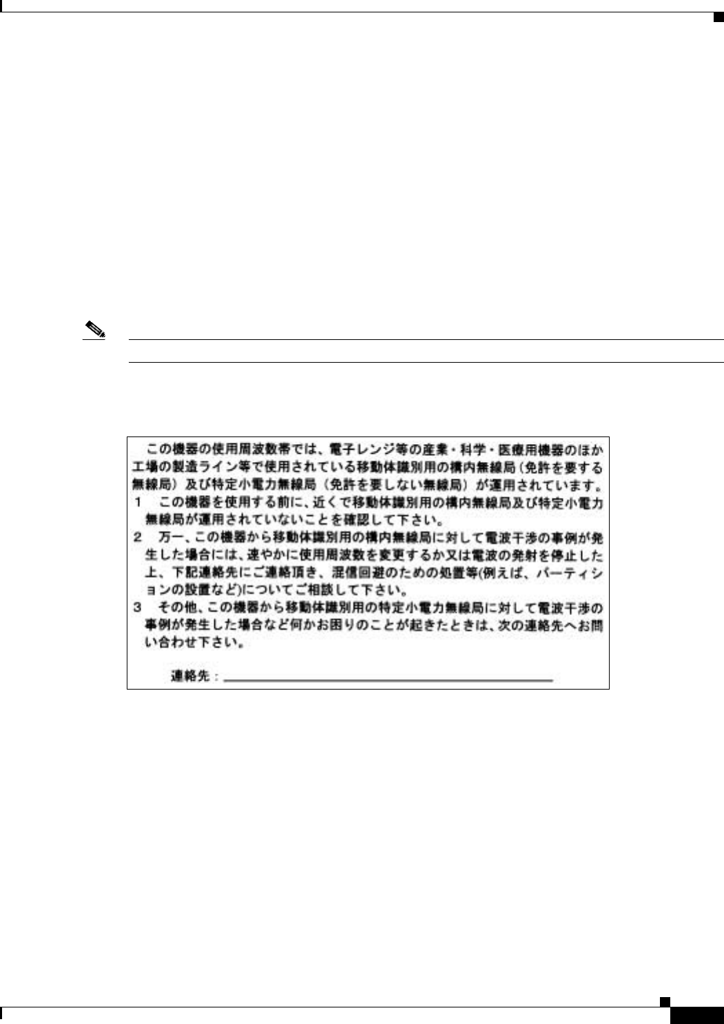
BETA DRAFT - CISCO CONFIDENTIAL
C-5
Cisco Aironet 802.11a/b/g Wireless LAN Client Adapters (CB21AG and PI21AG) Installation and Configuration Guide
OL-4211-01
Appendix C Declarations of Conformity and Regulatory Information Declaration of Conformity for RF Exposure
Declaration of Conformity for RF Exposure
The radio module has been evaluated under FCC Bulletin OET 65C and found compliant to the
requirements as set forth in CFR 47 Sections 2.1091, 2.1093, and 15.247 (b) (4) addressing RF Exposure
from radio frequency devices.
Guidelines for Operating Cisco Aironet Wireless LAN Client
Adapters in Japan
This section provides guidelines for avoiding interference when operating Cisco Aironet Wireless LAN
Client Adapters in Japan. These guidelines are provided in both Japanese and English.
Note The use of 5-GHz devices is limited to indoor use in Japan.
Japanese Translation
English Translation
This equipment operates in the same frequency bandwidth as industrial, scientific, and medical devices
such as microwave ovens and mobile object identification (RF-ID) systems (licensed premises radio
stations and unlicensed specified low-power radio stations) used in factory production lines.
1. Before using this equipment, make sure that no premises radio stations or specified low-power radio
stations of RF-ID are used in the vicinity.
2. If this equipment causes RF interference to a premises radio station of RF-ID, promptly change the
frequency or stop using the device; contact the number below and ask for recommendations on
avoiding radio interference, such as setting partitions.
3. If this equipment causes RF interference to a specified low-power radio station of RF-ID, contact
the number below.
Contact Number: 03-5549-6500
03-5549-6500
43768
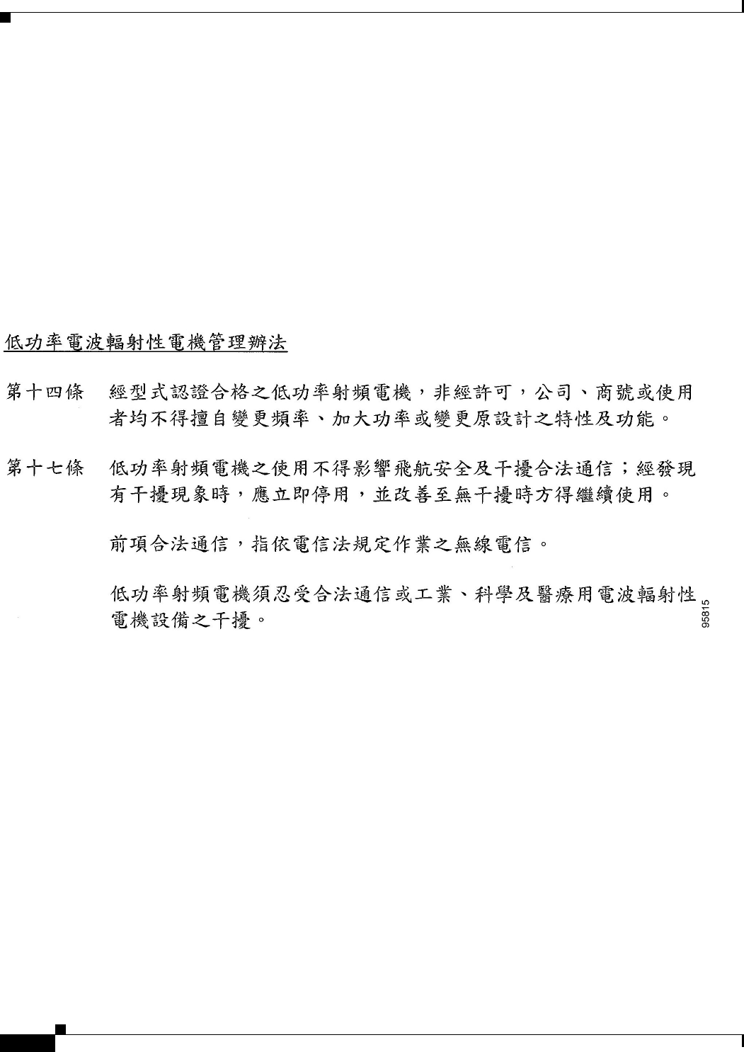
BETA DRAFT - CISCO CONFIDENTIAL
C-6
Cisco Aironet 802.11a/b/g Wireless LAN Client Adapters (CB21AG and PI21AG) Installation and Configuration Guide OL-4211-01
Appendix C Declarations of Conformity and Regulatory Information
Administrative Rules for Cisco Aironet Wireless LAN Client Adapters in Taiwan
Administrative Rules for Cisco Aironet Wireless LAN Client
Adapters in Taiwan
This section provides administrative rules for operating Cisco Aironet Wireless LAN Client Adapters in
Taiwan. The rules are provided in both Chinese and English.
2.4- and 5-GHz Client Adapters
Chinese Translation
English Translation
Administrative Rules for Low-power Radio-Frequency Devices
Article 14
For those low-power radio-frequency devices that have already received a type-approval, companies,
business units or users should not change its frequencies, increase its power or change its original
features and functions.
Article 17
The operation of the low-power radio-frequency devices is subject to the conditions that no harmful
interference is caused to aviation safety and authorized radio station; and if interference is caused, the
user must stop operating the device immediately and can't re-operate it until the harmful interference is
clear.

BETA DRAFT - CISCO CONFIDENTIAL
C-7
Cisco Aironet 802.11a/b/g Wireless LAN Client Adapters (CB21AG and PI21AG) Installation and Configuration Guide
OL-4211-01
Appendix C Declarations of Conformity and Regulatory Information Administrative Rules for Cisco Aironet Wireless LAN Client Adapters in Taiwan
The authorized radio station means a radio-communication service operating in accordance with
COMMUNICATION ACT.
The operation of the low-power radio-frequency devices is subject to the interference caused by the
operation of an authorized radio station, by another intentional or unintentional radiator, by industrial,
scientific and medical (ISM) equipment, or by an incidental radiator.
5-GHz Client Adapters
Chinese Translation
English Translation
This equipment is limited for indoor use.

BETA DRAFT - CISCO CONFIDENTIAL
C-8
Cisco Aironet 802.11a/b/g Wireless LAN Client Adapters (CB21AG and PI21AG) Installation and Configuration Guide OL-4211-01
Appendix C Declarations of Conformity and Regulatory Information
Administrative Rules for Cisco Aironet Wireless LAN Client Adapters in Taiwan

BETA DRAFT - CISCO CONFIDENTIAL
D-1
Cisco Aironet 802.11a/b/g Wireless LAN Client Adapters (CB21AG and PI21AG) Installation and Configuration Guide
OL-4211-01
APPENDIX
D
Channels, Power Levels, and Antenna Gains
This appendix lists the IEEE 802.11a, b, and g channels supported by the world's regulatory domains as
well as the maximum power levels and antenna gains allowed per data rate.
The following topics are covered in this appendix:
•Channels, page D-2
•Maximum Power Levels and Antenna Gains, page D-4

BETA DRAFT - CISCO CONFIDENTIAL
D-2
Cisco Aironet 802.11a/b/g Wireless LAN Client Adapters (CB21AG and PI21AG) Installation and Configuration Guide OL-4211-01
Appendix D Channels, Power Levels, and Antenna Gains
Channels
Channels
IEEE 802.11a
The channel identifiers, channel center frequencies, and regulatory domains of each IEEE 802.11a
20-MHz-wide channel are shown in Table D-1.
Note All channel sets are restricted to indoor usage except the Americas (-A), which allows for indoor and
outdoor use on channels 52 through 161 in the United States.
Table D-1 Channels for IEEE 802.11a
Channel
Identifier Frequency
(in MHz)
Regulatory Domains
Americas (-A) EMEA (-E) Japan (-J) Rest of World
(-W)
34 5170 ––X–
36 5180 X X –X
38 5190 ––X–
40 5200 X X –X
42 5210 ––X–
44 5220 X X –X
46 5230 ––X–
48 5240 X X –X
52 5260 X X –X
56 5280 X X –X
60 5300 X X –X
64 5320 X X –X
100 5500 –X––
104 5520 –X––
108 5540 –X––
112 5560 –X––
116 5580 –X––
120 5600 –X––
124 5620 –X––
128 5640 –X––
132 5660 –X––
136 5680 –X––
140 5700 –X––
149 5745 X ––X
153 5765 X ––X
157 5785 X ––X
161 5805 X ––X

BETA DRAFT - CISCO CONFIDENTIAL
D-3
Cisco Aironet 802.11a/b/g Wireless LAN Client Adapters (CB21AG and PI21AG) Installation and Configuration Guide
OL-4211-01
Appendix D Channels, Power Levels, and Antenna Gains Channels
IEEE 802.11b/g
The channel identifiers, channel center frequencies, and regulatory domains of each IEEE 802.11b/g
22-MHz-wide channel are shown in Table D-2.
Note Mexico is included in the Americas regulatory domain; however, channels 1 through 8 are for indoor use
only while channels 9 through 11 can be used indoors and outdoors. Users are responsible for ensuring
that the channel set configuration is in compliance with the regulatory standards of Mexico.
Note In Japan, channel 14 is not supported for 802.11g mode.
Table D-2 Channels for IEEE 802.11b/g
Channel
Identifier Frequency
(in MHz)
Regulatory Domains
Americas (-A) EMEA (-E) Japan (-J) Rest of World
(-W)
12412XXXX
22417XXXX
32422XXXX
42427XXXX
52432XXXX
62437XXXX
72442XXXX
82447XXXX
92452XXXX
102457XXXX
112462XXXX
12 2467 –XXX
13 2472 –XXX
14 2484 ––X–

BETA DRAFT - CISCO CONFIDENTIAL
D-4
Cisco Aironet 802.11a/b/g Wireless LAN Client Adapters (CB21AG and PI21AG) Installation and Configuration Guide OL-4211-01
Appendix D Channels, Power Levels, and Antenna Gains
Maximum Power Levels and Antenna Gains
Maximum Power Levels and Antenna Gains
IEEE 802.11a
An improper combination of power level and antenna gain can result in equivalent isotropic radiated
power (EIRP) above the amount allowed per regulatory domain. Table D-3 indicates the maximum
power levels and antenna gains allowed for each data rate in the IEEE 802.11a regulatory domains.
IEEE 802.11b
An improper combination of power level and antenna gain can result in equivalent isotropic radiated
power (EIRP) above the amount allowed per regulatory domain. Table D-5 indicates the maximum
power levels and antenna gains allowed for each data rate in the IEEE 802.11b regulatory domains.
Table D-3 Maximum Power Levels Per Antenna Gain for IEEE 802.11a
Data Rate
Maximum Power Level (mW)
for PC-Cardbus Card with 0-dBi
Antenna Gain
Maximum Power Level (mW)
for PCI Card with 1-dBi
Antenna Gain
6 Mbps 40 31.6
9 Mbps 40 31.6
12 Mbps 40 31.6
18 Mbps 40 31.6
24 Mbps 40 31.6
36 Mbps 25.1 25.1
48 Mbps 20 20
54 Mbps 20 20
Table D-4 Maximum Power Levels Per Antenna Gain for IEEE 802.11b
Data Rate
Maximum Power Level (mW)
for PC-Cardbus Card with 0-dBi
Antenna Gain
Maximum Power Level (mW)
for PCI Card with 1-dBi
Antenna Gain
1 Mbps 100 79
2 Mbps 100 79
5.5 Mbps 100 79
11 Mbps 100 79

BETA DRAFT - CISCO CONFIDENTIAL
D-5
Cisco Aironet 802.11a/b/g Wireless LAN Client Adapters (CB21AG and PI21AG) Installation and Configuration Guide
OL-4211-01
Appendix D Channels, Power Levels, and Antenna Gains Maximum Power Levels and Antenna Gains
IEEE 802.11g
An improper combination of power level and antenna gain can result in equivalent isotropic radiated
power (EIRP) above the amount allowed per regulatory domain. Table D-5 indicates the maximum
power levels and antenna gains allowed for each data rate in the IEEE 802.11g regulatory domains.
Table D-5 Maximum Power Levels Per Antenna Gain for IEEE 802.11g
Data Rate
Maximum Power Level (mW)
for PC-Cardbus Card with 0-dBi
Antenna Gain
Maximum Power Level (mW)
for PCI Card with 1-dBi
Antenna Gain
6 Mbps 45 35.8
9 Mbps 45 35.8
12 Mbps 45 35.8
18 Mbps 45 35.8
24 Mbps 45 35.8
36 Mbps 40 40
48 Mbps 31.6 31.6
54 Mbps 20 20

BETA DRAFT - CISCO CONFIDENTIAL
D-6
Cisco Aironet 802.11a/b/g Wireless LAN Client Adapters (CB21AG and PI21AG) Installation and Configuration Guide OL-4211-01
Appendix D Channels, Power Levels, and Antenna Gains
Maximum Power Levels and Antenna Gains

BETA DRAFT - CISCO CONFIDENTIAL
E-1
Cisco Aironet 802.11a/b/g Wireless LAN Client Adapters (CB21AG and PI21AG) Installation and Configuration Guide
OL-4211-01
APPENDIX
E
Configuring the Client Adapter through
Windows XP
This appendix explains how to configure and use the client adapter with Windows XP.
The following topics are covered in this appendix:
•Overview, page E-2
•Configuring the Client Adapter, page E-5
•Associating to an Access Point Using Windows XP, page E-17
•Viewing the Current Status of Your Client Adapter, page E-17

BETA DRAFT - CISCO CONFIDENTIAL
E-2
Cisco Aironet 802.11a/b/g Wireless LAN Client Adapters (CB21AG and PI21AG) Installation and Configuration Guide OL-4211-01
Appendix E Configuring the Client Adapter through Windows XP
Overview
Overview
This appendix provides instructions for minimally configuring the client adapter through Windows XP
(instead of through ADU) as well as for enabling one of the security options that are available for use
with this operating system. The “Overview of Security Features” section below describes each of these
options so that you can make an informed decision before you begin the configuration process.
In addition, this appendix also provides basic information on using Windows XP to specify the networks
to which the client adapter associates and to view the current status of your client adapter.
Note If you require more information about configuring or using your client adapter with Windows XP, refer
to Microsoft’s documentation for Windows XP.
Overview of Security Features
When you use your client adapter with Windows XP, you can protect your data as it is transmitted
through your wireless network by encrypting it through the use of wired equivalent privacy (WEP)
encryption keys. With WEP encryption, the transmitting device encrypts each packet with a WEP key,
and the receiving device uses that same key to decrypt each packet.
The WEP keys used to encrypt and decrypt transmitted data can be statically associated with your
adapter or dynamically created as part of the EAP authentication process. The information in the “Static
WEP Keys” and “EAP (with Dynamic WEP Keys)” sections below can help you to decide which type
of WEP keys you want to use. Dynamic WEP keys with EAP offer a higher degree of security than static
WEP keys.
WEP keys, whether static or dynamic, are either 40 or 128 bits in length. 128-bit WEP keys offer a greater
level of security than 40-bit WEP keys.
Static WEP Keys
Each device within your wireless network can be assigned up to four static WEP keys. If a device
receives a packet that is not encrypted with the appropriate key (as the WEP keys of all devices that are
to communicate with each other must match), the device discards the packet and never delivers it to the
intended receiver.
Static WEP keys are write-only and temporary; therefore, they cannot be read back from the client
adapter, and they are lost when power to the adapter is removed or the Windows device is rebooted.
Although the keys are temporary, you do not need to re-enter them each time the client adapter is inserted
or the Windows device is rebooted. This is because the keys are stored (in an encrypted format for
security reasons) in the registry of the Windows device. When the driver loads and reads the client
adapter’s registry parameters, it also finds the static WEP keys, unencrypts them, and stores them in
volatile memory on the adapter.

BETA DRAFT - CISCO CONFIDENTIAL
E-3
Cisco Aironet 802.11a/b/g Wireless LAN Client Adapters (CB21AG and PI21AG) Installation and Configuration Guide
OL-4211-01
Appendix E Configuring the Client Adapter through Windows XP Overview
EAP (with Dynamic WEP Keys)
The standard for wireless LAN security, as defined by the Institute of Electrical and Electronics
Engineers (IEEE), is called 802.1X for 802.11, or simply 802.1X. An access point that supports 802.1X
and its protocol, Extensible Authentication Protocol (EAP), acts as the interface between a wireless
client and an authentication server, such as a Remote Authentication Dial-In User Service (RADIUS)
server, to which the access point communicates over the wired network.
Two 802.1X authentication types are available when configuring your client adapter through
Windows XP:
•EAP-TLS—This authentication type uses a dynamic session-based WEP key, which is derived from
the client adapter and RADIUS server, to encrypt data.
RADIUS servers that support EAP-TLS include Cisco Secure ACS version 3.0 or greater and Cisco
Access Registrar version 1.8 or greater.
Note EAP-TLS requires the use of a certificate. Refer to Microsoft’s documentation for
information on downloading and installing the certificate.
•Protected EAP (or PEAP)—One of the following PEAP authentication types are available,
depending on the software that is installed on your computer:
–
PEAP (EAP-MSCHAP V2)—This PEAP authentication type is available if Cisco’s PEAP
security module (which is included in the Install Wizard file for Cisco Aironet 340, 350, and
CB20A client adapters) was not previously installed on your computer or was installed prior to
Service Pack 1 for Windows XP.
PEAP (EAP-MSCHAP V2) authentication supports only a Windows username and password. It
is based on EAP-TLS authentication but uses a password instead of a client certificate for
authentication. PEAP (EAP-MSCHAP V2) uses a dynamic session-based WEP key, which is
derived from the client adapter and RADIUS server, to encrypt data.
RADIUS servers that support PEAP (EAP-MSCHAP V2) authentication include Cisco Secure
ACS version 3.2 or greater.
–
PEAP (EAP-GTC)—This PEAP authentication type is available only if Cisco’s PEAP security
module (which is included in the Install Wizard file for Cisco Aironet 340, 350, and CB20A
client adapters) was previously installed on your computer and installed after Service Pack 1 for
Windows XP.
PEAP (EAP-GTC) authentication is designed to support One-Time Password (OTP) and
Windows NT or 2000 domain user databases over a wireless LAN. It is based on EAP-TLS
authentication but uses a password or PIN instead of a client certificate for authentication.
PEAP (EAP-GTC) uses a dynamic session-based WEP key, which is derived from the client
adapter and RADIUS server, to encrypt data. If your network uses an OTP user database, PEAP
(EAP-GTC) requires you to enter a software token PIN to start the EAP authentication process
and gain access to the network. If your network uses a Windows NT or 2000 domain user
database, PEAP (EAP-GTC) requires you to enter your username, password, and domain name
in order to start the authentication process.
RADIUS servers that support PEAP (EAP-GTC) authentication include Cisco Secure ACS
version 3.1 or greater.

BETA DRAFT - CISCO CONFIDENTIAL
E-4
Cisco Aironet 802.11a/b/g Wireless LAN Client Adapters (CB21AG and PI21AG) Installation and Configuration Guide OL-4211-01
Appendix E Configuring the Client Adapter through Windows XP
Overview
When you enable Require EAP on your access point and configure your client adapter for EAP-TLS or
PEAP using Windows XP, authentication to the network occurs in the following sequence:
1. The client adapter associates to an access point and begins the authentication process.
Note The client does not gain full access to the network until authentication between the client
and the RADIUS server is successful.
2. Communicating through the access point, the client and RADIUS server complete the authentication
process, with the password (PEAP) or certificate (EAP-TLS) being the shared secret for
authentication. The password or internal key is never transmitted during the process.
3. If authentication is successful, the client and RADIUS server derive a dynamic, session-based WEP
key that is unique to the client.
4. The RADIUS server transmits the key to the access point using a secure channel on the wired LAN.
5. For the length of a session, or time period, the access point and the client use this key to encrypt or
decrypt all unicast packets (and broadcast packets if the access point is set up to do so) that travel
between them.
Note Refer to the IEEE 802.11 Standard for more information on 802.1X authentication and to the following
URL for additional information on RADIUS servers:
http://www.cisco.com/univercd/cc/td/doc/product/software/ios120/12cgcr/secur_c/scprt2/scrad.htm
Wi-Fi Protected Access (WPA)
Wi-Fi Protected Access (WPA) is a standards-based, interoperable security enhancement that strongly
increases the level of data protection and access control for existing and future wireless LAN systems.
It is derived from and is forward-compatible with the upcoming IEEE 802.11i standard. WPA leverages
Temporal Key Integrity Protocol (TKIP) for data protection and 802.1X for authenticated key
management.
WPA supports two mutually exclusive key management types: WPA and WPA passphrase (or WPA
Pre-shared Key). Using WPA key management, clients and the authentication server authenticate to each
other using an EAP authentication method, and the client and server generate a pairwise master key
(PMK). Using WPA, the server generates the PMK dynamically and passes it to the access point. Using
WPA passphrase, however, you configure a passphrase (or pre-shared key) on both the client and the
access point, and that passphrase is used as the PMK.
A host supplicant with WPA support is required to use WPA. Windows XP Service Pack 1 and Microsoft
supplicant Q815485 are recommended for use with CB21AG and PI21AG client adapters. Service Pack
1 and the Q815485 supplicant can be downloaded from the following URLs:
•Service Pack 1:
http://www.microsoft.com/WindowsXP/pro/downloads/servicepacks/sp1/default.asp
•Q815485 supplicant:
http://www.microsoft.com/downloads/details.aspx?FamilyID=009d8425-ce2b-47a4-abec-274845d
c9e91&DisplayLang=en
Note WPA must also be enabled on the access point. Access points must use IOS release 12.2(11)JA or greater
to enable WPA. Refer to the documentation for your access point for instructions on enabling this
feature.
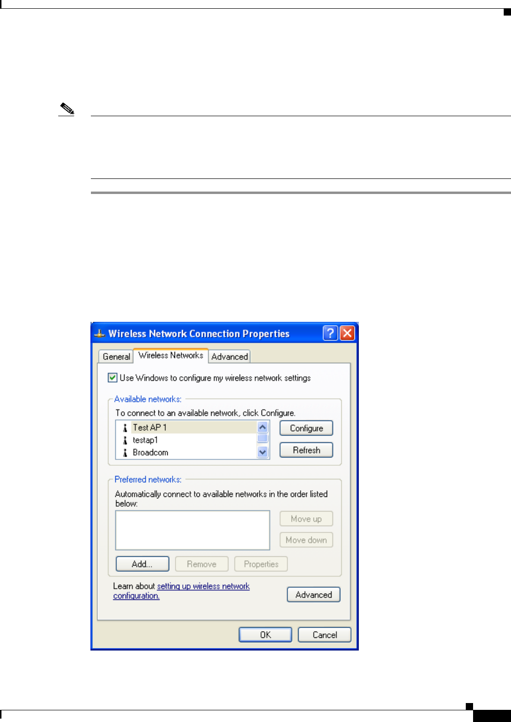
BETA DRAFT - CISCO CONFIDENTIAL
E-5
Cisco Aironet 802.11a/b/g Wireless LAN Client Adapters (CB21AG and PI21AG) Installation and Configuration Guide
OL-4211-01
Appendix E Configuring the Client Adapter through Windows XP Configuring the Client Adapter
Configuring the Client Adapter
Follow the steps below to configure your client adapter using Windows XP.
Note These instructions assume you are using the following:
- Windows XP Service Pack 1 and the Microsoft Q815485 supplicant
- Windows XP’s classic view rather than its category view
If you do not use Service Pack 1 and the Q815485 supplicant, the screens you see will look different than
those shown in this section and will not support PEAP and WPA.
Step 1 Make sure the client adapter’s driver has been installed and the client adapter is inserted in the Windows
XP device.
Step 2 Double-click My Computer, Control Panel, and Network Connections.
Step 3 Right-click Wireless Network Connection.
Step 4 Click Properties. The Wireless Network Connection Properties screen appears.
Step 5 Select the Wireless Networks tab. The following screen appears (see Figure E-1).
Figure E-1 Wireless Network Connection Properties Screen (Wireless Networks Tab)
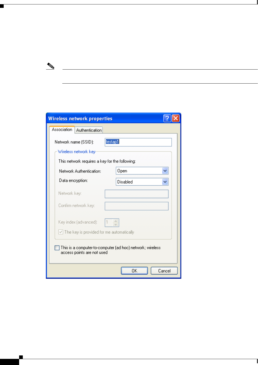
BETA DRAFT - CISCO CONFIDENTIAL
E-6
Cisco Aironet 802.11a/b/g Wireless LAN Client Adapters (CB21AG and PI21AG) Installation and Configuration Guide OL-4211-01
Appendix E Configuring the Client Adapter through Windows XP
Configuring the Client Adapter
Step 6 Make sure that the Use Windows to configure my wireless network settings check box is checked.
Step 7 Select the SSID of the access point to which you want the client adapter to associate from the list of
available networks and click Configure. If the SSID of the access point you want to use is not listed or
you are planning to operate the client adapter in an ad hoc network (a computer-to-computer network
without access points), click Add.
Note The Allow Broadcast SSID to Associate option on the access point must be enabled for the SSID
to appear in the list of available networks.
The Wireless Network Properties screen appears (see Figure E-2).
Figure E-2 Wireless Network Properties Screen (Association Tab)
Step 8 Perform one of the following:
•If you selected an SSID from the list of available networks, make sure the SSID appears in the
Network name (SSID) field.
•If you clicked Add, enter the case-sensitive SSID of the access point or the ad hoc network to which
you want the client adapter to associate in the Network name (SSID) field.

BETA DRAFT - CISCO CONFIDENTIAL
E-7
Cisco Aironet 802.11a/b/g Wireless LAN Client Adapters (CB21AG and PI21AG) Installation and Configuration Guide
OL-4211-01
Appendix E Configuring the Client Adapter through Windows XP Configuring the Client Adapter
Step 9 Check the This is a computer-to-computer (ad hoc mode) network; wireless access points are not
used check box at the bottom of the screen if you are planning to operate the client adapter in an ad hoc
network.
Step 10 Select one of the following options from the Network Authentication drop-down list:
•Open—Enables your client adapter, regardless of its WEP settings, to authenticate and attempt to
communicate with an access point. This option is recommended if you want to use static WEP or
EAP authentication without WPA.
•Shared—Enables your client adapter to communicate only with access points that have the same
WEP key. Cisco recommends that shared key authentication not be used because it presents a
security risk.
Note EAP-TLS does not work with shared key authentication because shared key authentication
requires the use of a WEP key, and a WEP key is not set for EAP-TLS until after the
completion of EAP authentication.
•WPA—Enables WPA, which enables your client adapter to associate to access points using WPA.
•WPA-PSK—Enables WPA Pre-shared key (WPA-PSK), which enables your client adapter to
associate to access points using WPA-PSK.
•WPA-None—Enables WPA for your client adapter when the client is set for ad hoc mode.
Note Refer to the “Wi-Fi Protected Access (WPA)” section on page E-4 for more information on WPA
and WPA-PSK.
Step 11 Select one of the following options from the Data encryption drop-down list:
•Disabled—Disables data encryption for your client adapter. This option is available only when
Open or Shared has been selected for Network Authentication.
•WEP—Enables static or dynamic WEP for your client adapter. This option is recommended for use
with open authentication.
•TKIP—Enables Temporal Key Integrity Protocol (TKIP) for your client adapter. This option is
recommended for use with WPA and WPA-PSK.
Step 12 Follow the steps below to enter a static WEP key if you are planning to use static WEP.
Note If you are planning to use EAP-TLS or PEAP authentication, which uses dynamic WEP, go to •.
a. Make sure the The key is provided for me automatically check box is unchecked.
b. Obtain the WEP key for the access point (in an infrastructure network) or other clients (in an ad hoc
network) from your system administrator and enter it in both the Network key and Confirm network
key fields. Follow the guidelines below to enter a new static WEP key:
•WEP keys must contain the following number of characters:
–
10 hexadecimal characters or 5 ASCII text characters for 40-bit keys
Example: 5A5A313859 (hexadecimal) or ZZ18Y (ASCII)
–
26 hexadecimal characters or 13 ASCII text characters for 128-bit keys
Example: 5A583135333554595549333534 (hexadecimal) or ZX1535TYUI354 (ASCII)

BETA DRAFT - CISCO CONFIDENTIAL
E-8
Cisco Aironet 802.11a/b/g Wireless LAN Client Adapters (CB21AG and PI21AG) Installation and Configuration Guide OL-4211-01
Appendix E Configuring the Client Adapter through Windows XP
Configuring the Client Adapter
Note You must enter hexadecimal characters for 5-GHz client adapters if these adapters will
be used with Cisco Aironet 1200 Series Access Points.
•Your client adapter’s WEP key must match the WEP key used by the access point (in
infrastructure mode) or clients (in ad hoc mode) with which you are planning to communicate.
c. In the Key index (advanced) field, select the number of the WEP key you are creating (1, 2, 3, or 4).
Note The WEP key must be assigned to the same number on both the client adapter and the access
point (in an infrastructure network) or other clients (in an ad hoc network).
d. Click OK to save your settings and to add this SSID to the list of preferred networks (see
Figure E-1). The configuration is complete for static WEP. The client adapter automatically attempts
to associate to the network(s) in the order in which they are listed.
Step 13 If you enabled WPA-PSK or WPA-None, obtain the pre-shared key for the access point (in an
infrastructure network) or other clients (in an ad hoc network) from your system administrator and enter
it in both the Network key and Confirm network key fields. Follow the guidelines below to enter a
pre-shared key:
•Pre-shared keys must contain 8 to 63 ASCII text characters or 64 hexadecimal characters.
Note You must enter hexadecimal characters for 5-GHz client adapters if these adapters will be
used with Cisco Aironet 1200 Series Access Points.
•Your client adapter’s pre-shared key must match the pre-shared key used by the access point (in
infrastructure mode) or clients (in ad hoc mode) with which you are planning to communicate.
Step 14 Check the The key is provided for me automatically check box if you are planning to use EAP-TLS
or PEAP, which uses dynamic WEP keys.
Note This parameter is not available if you enabled WPA or WPA-PSK.
Step 15 Perform one of the following if you are planning to use EAP authentication:
•If you are planning to use EAP-TLS authentication, follow the instructions in the “Enabling
EAP-TLS Authentication” section below.
•If you are planning to use PEAP authentication, follow the instructions in the “Enabling PEAP
Authentication” section on page E-12.
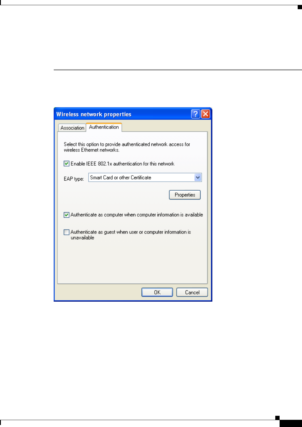
BETA DRAFT - CISCO CONFIDENTIAL
E-9
Cisco Aironet 802.11a/b/g Wireless LAN Client Adapters (CB21AG and PI21AG) Installation and Configuration Guide
OL-4211-01
Appendix E Configuring the Client Adapter through Windows XP Configuring the Client Adapter
Enabling EAP-TLS Authentication
Follow the steps below to prepare the client adapter to use EAP-TLS authentication, provided you have
completed the initial configuration.
Step 1 Click the Authentication tab on the Wireless Network Properties screen. The following screen appears
(see Figure E-3).
Figure E-3 Wireless Network Properties Screen (Authentication Tab)
Step 2 Check the Enable IEEE 802.1x authentication for this network check box if you did not enable WPA
or WPA-PSK on the Association screen.
Step 3 For EAP type, select Smart Card or other Certificate.
Step 4 Click Properties. The Smart Card or other Certificate Properties screen appears (see Figure E-4).
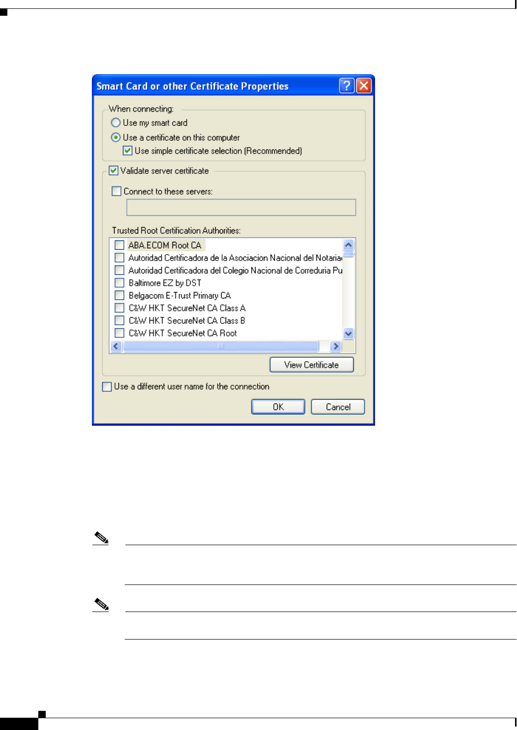
BETA DRAFT - CISCO CONFIDENTIAL
E-10
Cisco Aironet 802.11a/b/g Wireless LAN Client Adapters (CB21AG and PI21AG) Installation and Configuration Guide OL-4211-01
Appendix E Configuring the Client Adapter through Windows XP
Configuring the Client Adapter
Figure E-4 Smart Card or other Certificate Properties Screen
Step 5 Select the Use a certificate on this computer option.
Step 6 Check the Use simple certificate selection (Recommended) check box.
Step 7 Check the Validate server certificate check box if server certificate validation is required.
Step 8 If you want to specify the name of the server to connect to, check the Connect to these servers check
box and enter the server name in the field below.
Note If you enter a server name and the client adapter connects to a server that does not match the
name you entered, you are prompted to accept or cancel the connection during the authentication
process.
Note If you leave this field blank, the server name is not verified, and a connection is established as
long as the certificate is valid.

BETA DRAFT - CISCO CONFIDENTIAL
E-11
Cisco Aironet 802.11a/b/g Wireless LAN Client Adapters (CB21AG and PI21AG) Installation and Configuration Guide
OL-4211-01
Appendix E Configuring the Client Adapter through Windows XP Configuring the Client Adapter
Step 9 In the Trusted Root Certification Authorities field, check the check box beside the name of the certificate
authority from which the server certificate was downloaded.
Note If you leave all check boxes unchecked, you are prompted to accept a connection to the root
certification authority during the authentication process.
Step 10 Click OK three times to save your settings. The configuration is complete.
Step 11 If a pop-up message appears above the system tray informing you that you need to accept a certificate
to begin the EAP authentication process, click the message and follow the instructions provided to accept
the certificate.
Note You should not be prompted to accept a certificate for future authentication attempts. After you
accept one, the same certificate is used subsequently.
Step 12 If a message appears indicating the root certification authority for the server’s certificate, and it is the
correct certification authority, click OK to accept the connection. Otherwise, click Cancel.
Step 13 If a message appears indicating the server to which your client adapter is connected, and it is the correct
server to connect to, click OK to accept the connection. Otherwise, click Cancel.
The client adapter should now EAP authenticate.
Note Whenever the computer reboots and you enter your Windows username and password, the EAP
authentication process begins automatically and the client adapter should EAP authenticate.
Step 14 To verify authentication, double-click My Computer, Control Panel, and Network Connections. The
status appears to the right of your Wireless Network Connection. Click View and Refresh to obtain the
current status. If the client adapter is authenticated, the status reads Authentication succeeded.
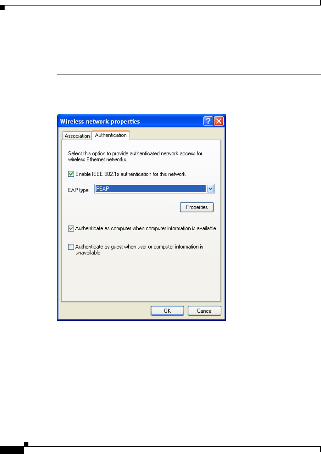
BETA DRAFT - CISCO CONFIDENTIAL
E-12
Cisco Aironet 802.11a/b/g Wireless LAN Client Adapters (CB21AG and PI21AG) Installation and Configuration Guide OL-4211-01
Appendix E Configuring the Client Adapter through Windows XP
Configuring the Client Adapter
Enabling PEAP Authentication
Follow the steps below to prepare the client adapter to use PEAP authentication, provided you have
completed the initial configuration.
Step 1 Click the Authentication tab on the Wireless Network Properties screen. The following screen appears
(see Figure E-5).
Figure E-5 Wireless Network Properties Screen (Authentication Tab)
Step 2 Check the Enable IEEE 802.1x authentication for this network check box if you did not enable WPA
or WPA-PSK on the Association screen.
Step 3 For EAP type, select one of the following, depending on the software that is installed on your computer:
•Protected EAP (PEAP)—This option appears for PEAP (EAP-MSCHAP V2).
•PEAP—This option appears for PEAP (EAP-GTC).
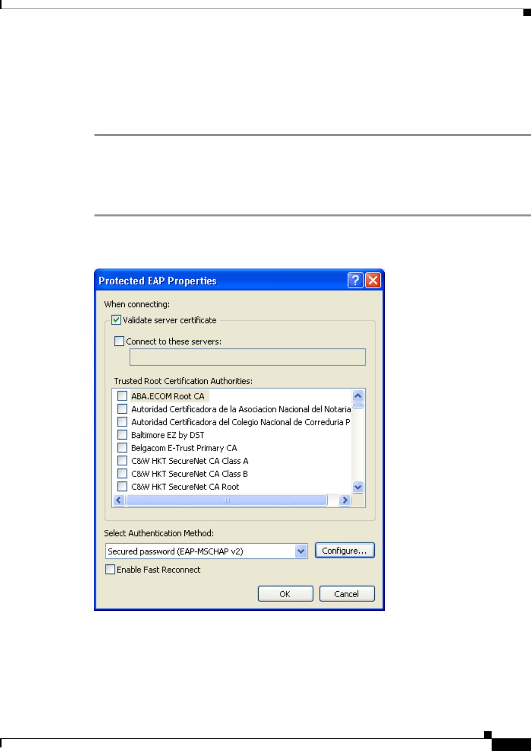
BETA DRAFT - CISCO CONFIDENTIAL
E-13
Cisco Aironet 802.11a/b/g Wireless LAN Client Adapters (CB21AG and PI21AG) Installation and Configuration Guide
OL-4211-01
Appendix E Configuring the Client Adapter through Windows XP Configuring the Client Adapter
Step 4 Perform one of the following:
•If you selected Protected EAP (PEAP), follow the instructions in the “Enabling PEAP
(EAP-MSCHAP V2)” section below.
•If you selected PEAP, follow the instructions in the “Enabling PEAP (EAP-GTC)” section on
page E-15.
Enabling PEAP (EAP-MSCHAP V2)
Follow the steps below to enable PEAP (EAP-MSCHAP V2).
Step 1 Click Properties. The Protected EAP Properties screen appears (see Figure E-8).
Figure E-6 Protected EAP Properties Screen
Step 2 Check the Validate server certificate check box if server certificate validation is required
(recommended).
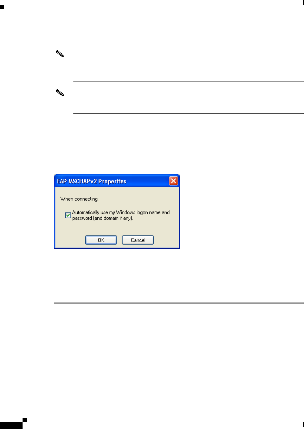
BETA DRAFT - CISCO CONFIDENTIAL
E-14
Cisco Aironet 802.11a/b/g Wireless LAN Client Adapters (CB21AG and PI21AG) Installation and Configuration Guide OL-4211-01
Appendix E Configuring the Client Adapter through Windows XP
Configuring the Client Adapter
Step 3 If you want to specify the name of the server to connect to, check the Connect to these servers check
box and enter the appropriate server name in the field below.
Note If you enter a server name and the client adapter connects to a server that does not match the
name you entered, you are prompted to accept or cancel the connection during the authentication
process.
Note If you leave this field blank, the server name is not verified, and a connection is established as
long as the certificate is valid.
Step 4 In the Trusted Root Certification Authorities field, select the certificate authority from which the server
certificate was downloaded.
Step 5 In the Select Authentication Method drop-down box, select Secured password (EAP-MSCHAP v2).
Step 6 Click Configure. The EAP MSCHAPv2 Properties screen appears (see Figure E-7).
Figure E-7 EAP MSCHAPv2 Properties Screen
Step 7 Make sure the Automatically use my Windows logon name and password (and domain if any) check
box is checked.
Step 8 Click OK four times to save your settings. The configuration is complete.
Step 9 Refer to the “Using PEAP” section on page 6-10 for instructions on authenticating using PEAP.
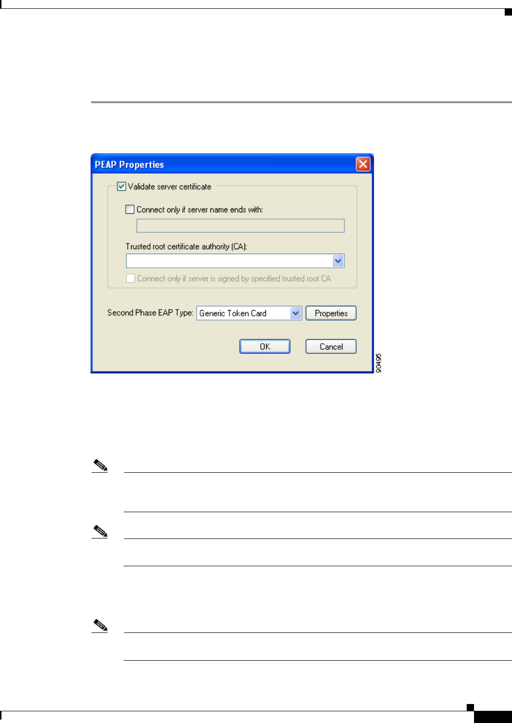
BETA DRAFT - CISCO CONFIDENTIAL
E-15
Cisco Aironet 802.11a/b/g Wireless LAN Client Adapters (CB21AG and PI21AG) Installation and Configuration Guide
OL-4211-01
Appendix E Configuring the Client Adapter through Windows XP Configuring the Client Adapter
Enabling PEAP (EAP-GTC)
Follow the steps below to enable PEAP (EAP-GTC).
Step 1 Click Properties. The PEAP Properties screen appears (see Figure E-8).
Figure E-8 PEAP Properties Screen
Step 2 Check the Validate server certificate check box if server certificate validation is required
(recommended).
Step 3 If you want to specify the name of the server to connect to, check the Connect only if server name ends
with check box and enter the appropriate server name suffix in the field below.
Note If you enter a server name and the client adapter connects to a server that does not match the
name you entered, you are prompted to accept or cancel the connection during the authentication
process.
Note If you leave this field blank, the server name is not verified, and a connection is established as
long as the certificate is valid.
Step 4 Make sure that the name of the certificate authority from which the server certificate was downloaded
appears in the Trusted root certificate authority (CA) field. If necessary, click the arrow on the
drop-down menu and select the appropriate name.
Note If you leave this field blank, you are prompted to accept a connection to the root certification
authority during the authentication process.
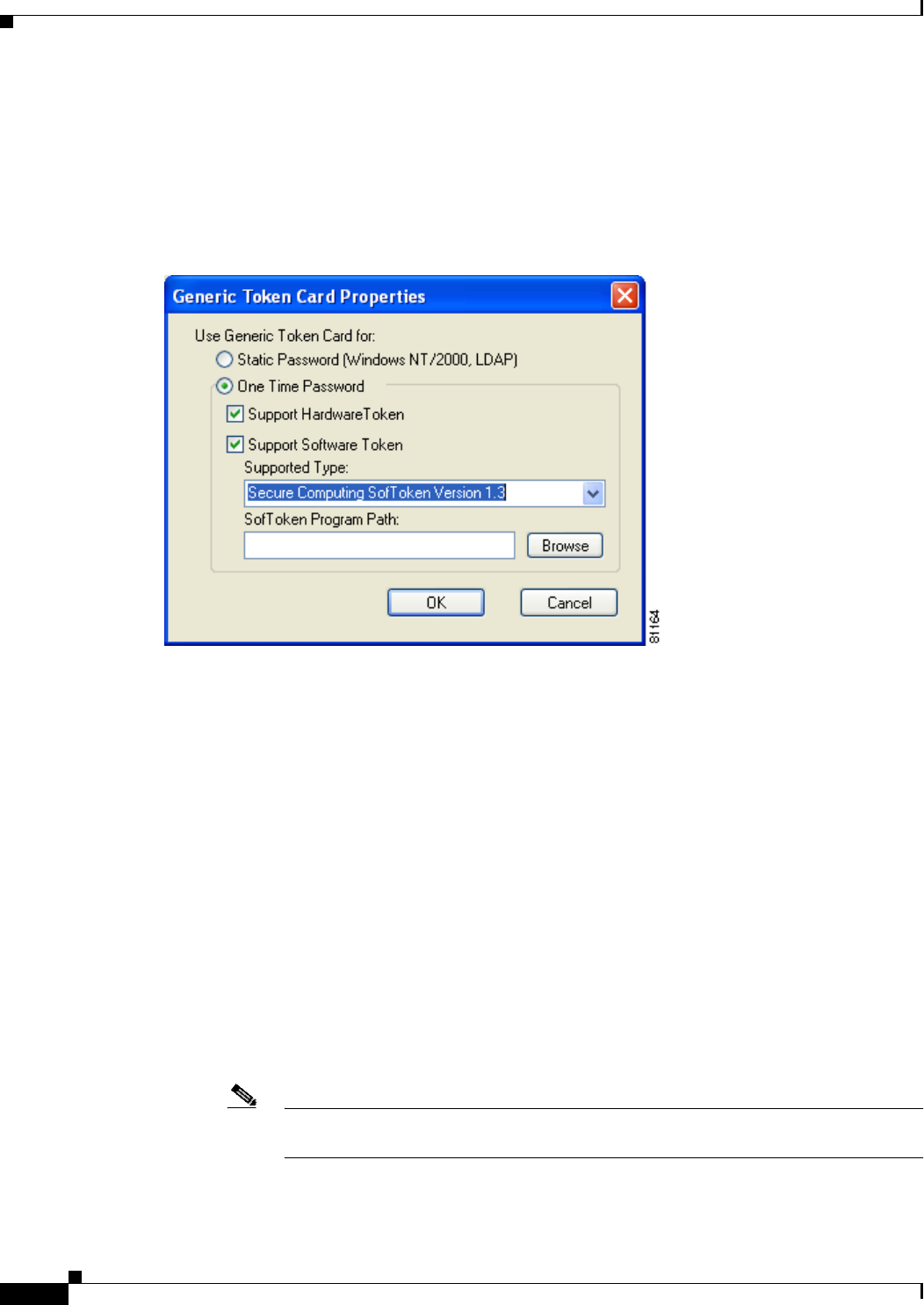
BETA DRAFT - CISCO CONFIDENTIAL
E-16
Cisco Aironet 802.11a/b/g Wireless LAN Client Adapters (CB21AG and PI21AG) Installation and Configuration Guide OL-4211-01
Appendix E Configuring the Client Adapter through Windows XP
Configuring the Client Adapter
Step 5 Check the Connect only if server is signed by specified trusted root CA check box if you want to
ensure that the certificate server uses the trusted root certificate specified in the field above. This
prevents the client from establishing connections to rogue access points.
Step 6 Currently Generic Token Card is the only second phase EAP type available. Click Properties. The
Generic Token Card Properties screen appears (see Figure E-9).
Figure E-9 Generic Token Card Properties Screen
Step 7 Select either the Static Password (Windows NT/2000, LDAP) or the One Time Password option,
depending on your user database.
Step 8 Perform one of the following:
•If you selected the Static Password (Windows NT/2000, LDAP) option in Step 7, go to Step 9.
•If you selected the One Time Password option in Step 7, check one or both of the following check
boxes to specify the type of tokens that will be supported for one-time passwords:
–
Support Hardware Token—A hardware token device obtains the one-time password. You
must use your hardware token device to obtain the one-time password and enter the password
when prompted for your user credentials.
–
Support Software Token—The PEAP supplicant works with a software token program to
retrieve the one-time password. You have to enter only the PIN, not the one-time password. If
you check this check box, you must also select from the Supported Type drop-down box the
software token software that is installed on the client (such as Secure Computing SofToken
Version 1.3, Secure Computing SofToken II 2.0, or RSA SecurID Software Token v 2.5), and if
Secure Computing SofToken Version 1.3 is selected, you must find the software program path
using the Browse button.
Note The SofToken Program Path field is unavailable if a software token program other than
Secure Computing SofToken Version 1.3 is selected.

BETA DRAFT - CISCO CONFIDENTIAL
E-17
Cisco Aironet 802.11a/b/g Wireless LAN Client Adapters (CB21AG and PI21AG) Installation and Configuration Guide
OL-4211-01
Appendix E Configuring the Client Adapter through Windows XP Associating to an Access Point Using Windows XP
Step 9 Click OK four times to save your settings. The configuration is complete.
Step 10 Refer to the “Using PEAP” section on page 6-10 for instructions on authenticating using PEAP.
Associating to an Access Point Using Windows XP
Windows XP causes the client adapter’s driver to automatically attempt to associate to the first network
in the list of preferred networks (see Figure E-1). If the adapter fails to associate or loses association, it
automatically switches to the next network in the list of preferred networks.The adapter does not switch
networks as long as it remains associated to the access point. To force the client adapter to associate to
a different access point, you must select a different network from the list of available networks (and click
Configure and OK).
Viewing the Current Status of Your Client Adapter
To view the status of your client adapter, click the icon of the two connected computers in the Windows
system tray. The Wireless Network Connection Status screen appears (see Figure E-10).
Figure E-10 Wireless Network Connection Status Screen

BETA DRAFT - CISCO CONFIDENTIAL
E-18
Cisco Aironet 802.11a/b/g Wireless LAN Client Adapters (CB21AG and PI21AG) Installation and Configuration Guide OL-4211-01
Appendix E Configuring the Client Adapter through Windows XP
Viewing the Current Status of Your Client Adapter

BETA DRAFT - CISCO CONFIDENTIAL
GL-1
Cisco Aironet 802.11a/b/g Wireless LAN Client Adapters (CB21AG and PI21AG) Installation and Configuration Guide
OL-4211-01
GLOSSARY
16-QAM Quadrate amplitude modulation. A modulation technique used by IEEE 802.11-compliant wireless
LANs for transmission at 24 and 36 Mbps.
64-QAM Quadrate amplitude modulation. A modulation technique used by IEEE 802.11-compliant wireless
LANs for transmission at 48 and 54 Mbps.
802.1X Also called 802.1X for 802.11. 802.1X is the new standard for wireless LAN security, as defined by the
Institute of Electrical and Electronics Engineers (IEEE). An access point that supports 802.1X and its
protocol, Extensible Authentication Protocol (EAP), acts as the interface between a wireless client and an
authentication server, such as a Remote Authentication Dial-In User Service (RADIUS) server, to which the
access point communicates over the wired network.
802.11 The IEEE standard that specifies carrier sense media access control and physical layer specifications
for 1- and 2-megabit-per-second (Mbps) 2.4-GHz wireless LANs.
802.11a The IEEE standard that governs the deployment of 5-GHz OFDM systems. It specifies the
implementation of the physical layer for wireless UNII bands (see UNII, UNII 1, and UNII 2) and
provides four channels per 100 MHz of bandwidth.
802.11b The IEEE standard that specifies carrier sense media access control and physical layer specifications
for 5.5- and 11-Mbps 2.4-GHz wireless LANs.
802.11g The IEEE standard that specifies carrier sense media access control and physical layer specifications
for 54-Mbps 2.4-GHz wireless LANs.
A
Access Point A wireless LAN data transceiver that uses radio waves to connect a wired network with wireless
stations.
Ad Hoc Network A wireless network composed of stations without access points.
Alphanumeric A set of characters that contains both letters and numbers.
Associated A station is configured properly to allow it to wirelessly communicate with an access point.

BETA DRAFT - CISCO CONFIDENTIAL
Glossary
GL-2
Cisco Aironet 802.11a/b/g Wireless LAN Client Adapters (CB21AG and PI21AG) Installation and Configuration Guide OL-4211-01
B
Bandwidth Specifies the amount of the frequency spectrum that is usable for data transfer. It identifies the
maximum data rate that a signal can attain on the medium without encountering significant power loss.
BPSK Binary phase shift keying. A modulation technique used by IEEE 802.11-compliant wireless LANs for
transmission at 1 Mbps.
Broadcast key
rotation A security feature for use with dynamic WEP keys. If your client adapter uses LEAP, EAP-TLS, or
PEAP authentication and you enable this feature, the access point changes the dynamic broadcast WEP
key that it provides at the interval you select.
C
CCK Complementary code keying. A modulation technique used by IEEE 802.11b-compliant wireless LANs
for transmission at 5.5 and 11 Mbps.
CCKM Cisco Centralized Key Management. Using CCKM, authenticated client devices can roam from one
access point to another without any perceptible delay during reassociation. An access point on your
network provides wireless domain services (WDS) and creates a cache of security credentials for
CCKM-enabled client devices on the subnet. The WDS access point's cache of credentials dramatically
reduces the time required for reassociation when a CCKM-enabled client device roams to a new access
point.
CKIP Cisco Key Integrity Protocol. Cisco’s WEP key permutation technique based on an early algorithm
presented by the IEEE 802.11i security task group.
Client A radio device that uses the services of an access point to communicate wirelessly with other devices
on a local area network.
CSMA Carrier sense multiple access. A wireless LAN media access method specified by the IEEE 802.11
specification.
Cyclic Redundancy
Check (CRC) A method of checking for errors in a received packet.
D
Data Rates The range of data transmission rates supported by a device. Data rates are measured in megabits per
second (Mbps).
dBi A ratio of decibels to an isotropic antenna that is commonly used to measure antenna gain. The greater
the dBi value, the higher the gain and the more acute the angle of coverage.
DHCP Dynamic Host Configuration Protocol. A protocol available with many operating systems that
automatically issues IP addresses within a specified range to devices on the network. The device retains
the assigned address for a specific administrator-defined period.
Dipole A type of low-gain (2.2-dBi) antenna consisting of two (often internal) elements.

BETA DRAFT - CISCO CONFIDENTIAL
Glossary
GL-3
Cisco Aironet 802.11a/b/g Wireless LAN Client Adapters (CB21AG and PI21AG) Installation and Configuration Guide
OL-4211-01
DSSS Direct-sequence spread spectrum. A type of spread spectrum radio transmission that spreads its signal
continuously over a wide frequency band.
Duplicate Packets Packets that were received twice because an acknowledgement got lost and the sender retransmitted the
packet.
E
EAP Extensible Authentication Protocol. EAP is the protocol for the optional IEEE 802.1X wireless LAN
security feature. An access point that supports 802.1X and EAP acts as the interface between a wireless
client and an authentication server, such as a Remote Authentication Dial-In User Service (RADIUS) server,
to which the access point communicates over the wired network.
Ethernet The most widely used wired local area network. Ethernet uses carrier sense multiple access (CSMA)
to allow computers to share a network and operates at 10, 100, or 1000 megabits per second (Mbps),
depending on the physical layer used.
F
File Server A repository for files so that a local area network can share files, mail, and programs.
Fragmentation
Threshold The size at which packets are fragmented and transmitted a piece at a time instead of all at once. The
setting must be within the range of 64 to 2312 bytes.
Full Duplex A means of communication whereby each node receives and transmits simultaneously (two-way). See
also Half Duplex.
G
Gateway A device that connects two otherwise incompatible networks together.
GHz Gigahertz. One billion cycles per second. A unit of measure for frequency.
H
Half Duplex A means of communication whereby each node receives and transmits in turn (one-way). See also Full
Duplex.
Hexadecimal A set of characters consisting of ten numbers and six letters (0-9, A-F, and a-f).

BETA DRAFT - CISCO CONFIDENTIAL
Glossary
GL-4
Cisco Aironet 802.11a/b/g Wireless LAN Client Adapters (CB21AG and PI21AG) Installation and Configuration Guide OL-4211-01
.
I
IEEE Institute of Electrical and Electronics Engineers. A professional society serving electrical engineers
through its publications, conferences, and standards development activities. The body responsible for
the Ethernet 802.3 and wireless LAN 802.11 specifications.
Infrastructure The wired Ethernet network.
Infrastructure
Device A device (such as an access point, bridge, or base station) that connects client adapters to a wired LAN.
IP Address The Internet Protocol (IP) address of a station.
IP Subnet Mask The number used to identify the IP subnetwork, indicating whether the IP address can be recognized
on the LAN or if it must be reached through a gateway.
IPX Internetwork Packet Exchange. The NetWare network layer protocol used for transferring data from
servers to workstations.
Isotropic An antenna that radiates its signal 360 degrees both vertically and horizontally in a perfect sphere.
L
LEAP LEAP, or EAP-Cisco Wireless, is the 802.1X authentication type that is available for use with operating
systems that do not have EAP support. Support for LEAP is provided in the client adapter’s firmware
and the Cisco software that supports it, rather than in the operating system. With LEAP, a username and
password are used by the client adapter to perform mutual authentication with the RADIUS server
through an access point.
M
MAC Address The Media Access Control (MAC) address is a unique serial number assigned to a networking device
by the manufacturer.
MIC Message integrity check. MIC prevents bit-flip attacks on encrypted packets. During a bit-flip attack,
an intruder intercepts an encrypted message, alters it slightly, and retransmits it, and the receiver
accepts the retransmitted message as legitimate. The client adapter’s driver must support MIC
functionality, and MIC must be enabled on the access point.
Modulation Any of several techniques for combining user information with a transmitter’s carrier signal.
Multicast Packets Packets transmitted to multiple stations.
Multipath The echoes created as a radio signal bounces off of physical objects.

BETA DRAFT - CISCO CONFIDENTIAL
Glossary
GL-5
Cisco Aironet 802.11a/b/g Wireless LAN Client Adapters (CB21AG and PI21AG) Installation and Configuration Guide
OL-4211-01
O
OFDM Orthogonal frequency division multiplexing. A multicarrier modulation method for broadband wireless
communications.
Overrun Packets Packets that were discarded because the access point had a temporary overload of packets to handle.
P
Packet A basic message unit for communication across a network. A packet usually includes routing
information, data, and sometimes error detection information.
Q
QPSK Quadruple phase shift keying. A modulation technique used by IEEE 802.11-compliant wireless LANs
for transmission at 2 Mbps.
R
Radio Channel The frequency at which a radio operates.
Range A linear measure of the distance that a transmitter can send a signal.
Receiver Sensitivity A measurement of the weakest signal a receiver can receive and still correctly translate it into data.
RF Radio frequency. A generic term for radio-based technology.
Roaming A feature of some access points that allows users to move through a facility while maintaining an
unbroken connection to the LAN.
RP-TNC A connector type unique to Cisco Aironet radios and antennas. Part 15.203 of the FCC rules covering
spread spectrum devices limits the types of antennas that may be used with transmission equipment. In
compliance with this rule, Cisco Aironet, like all other wireless LAN providers, equips its radios and
antennas with a unique connector to prevent attachment of non-approved antennas to radios.
RTS Threshold The packet size at which an access point issues a request to send (RTS) before sending the packet.
S
Spread Spectrum A radio transmission technology that spreads data over a much wider bandwidth than otherwise
required in order to gain benefits such as improved interference tolerance and unlicensed operation.
SSID Service set identifier. A unique identifier that stations must use to be able to communicate with an
access point. The SSID can be any alphanumeric entry up to a maximum of 32 characters.

BETA DRAFT - CISCO CONFIDENTIAL
Glossary
GL-6
Cisco Aironet 802.11a/b/g Wireless LAN Client Adapters (CB21AG and PI21AG) Installation and Configuration Guide OL-4211-01
T
TKIP Temporal Key Integrity Protocol. Also referred to as WEP key hashing. A security feature that defends
against an attack on WEP in which the intruder uses the initialization vector (IV) in encrypted packets
to calculate the WEP key. TKIP removes the predictability that an intruder relies on to determine the
WEP key by exploiting IVs.
Transmit Power The power level of radio transmission.
U
Unicast Packets Packets transmitted in point-to-point communication.
UNII Unlicensed National Information Infrastructure. An FCC regulatory domain for 5-GHz wireless
devices. UNII bands are 100 MHz wide and divided into four channels when using 802.11a OFDM
modulation.
UNII 1 A UNII band dedicated to in-building wireless LAN applications. UNII 1 is located at 5.15 to 5.25 GHz
and allows for a maximum transmit power of 40 mW (or 16 dBm) with an antenna up to 6 dBi. UNII 1
regulations require a nonremovable, integrated antenna.
UNII 2 A UNII band dedicated to in-building wireless LAN applications. UNII 2 is located at 5.25 to 5.35 GHz
and allows for a maximum transmit power of 200 mW (or 23 dBm) with an antenna up to 6 dBi. UNII
2 regulations allow for an auxiliary, user-installable antenna.
UNII 3 A UNII band dedicated to wireless LAN applications. UNII 3 is located at 5.725 to 5.825 GHz and
allows for a maximum transmit power of 1 Watt (or 30 dBm) with an antenna up to 6 dBi. UNII 3
regulations allow for an auxiliary, user-installable antenna.
W
WDS Wireless domain services (WDS). An access point providing WDS on your wireless LAN maintains a
cache of credentials for CCKM-capable client devices on your wireless LAN. When a CCKM-capable
client roams from one access point to another, the WDS access point forwards the client's credentials
to the new access point with the multicast key. Only two packets pass between the client and the new
access point, greatly shortening the reassociation time.
WEP Wired equivalent privacy. An optional security mechanism defined within the 802.11 standard designed
to protect your data as it is transmitted through your wireless network by encrypting it through the use
of encryption keys.
Workstation A computing device with an installed client adapter.
WPA Wi-Fi Protected Access. A standards-based, interoperable security enhancement that strongly increases
the level of data protection and access control for existing and future wireless LAN systems. It is
derived from and will be compatible with the upcoming IEEE 802.11i standard. WPA leverages
Temporal Key Integrity Protocol (TKIP) for data protection and 802.1X for authenticated key
management.

BETA DRAFT - CISCO CONFIDENTIAL
IN-1
Cisco Aironet 802.11a/b/g Wireless LAN Client Adapters (CB21AG and PI21AG) Installation and Configuration Guide
OL-4211-01
INDEX
To Be Added

BETA DRAFT - CISCO CONFIDENTIAL
Index
IN-2
Cisco Aironet 802.11a/b/g Wireless LAN Client Adapters (CB21AG and PI21AG) Installation and Configuration Guide OL-4211-01