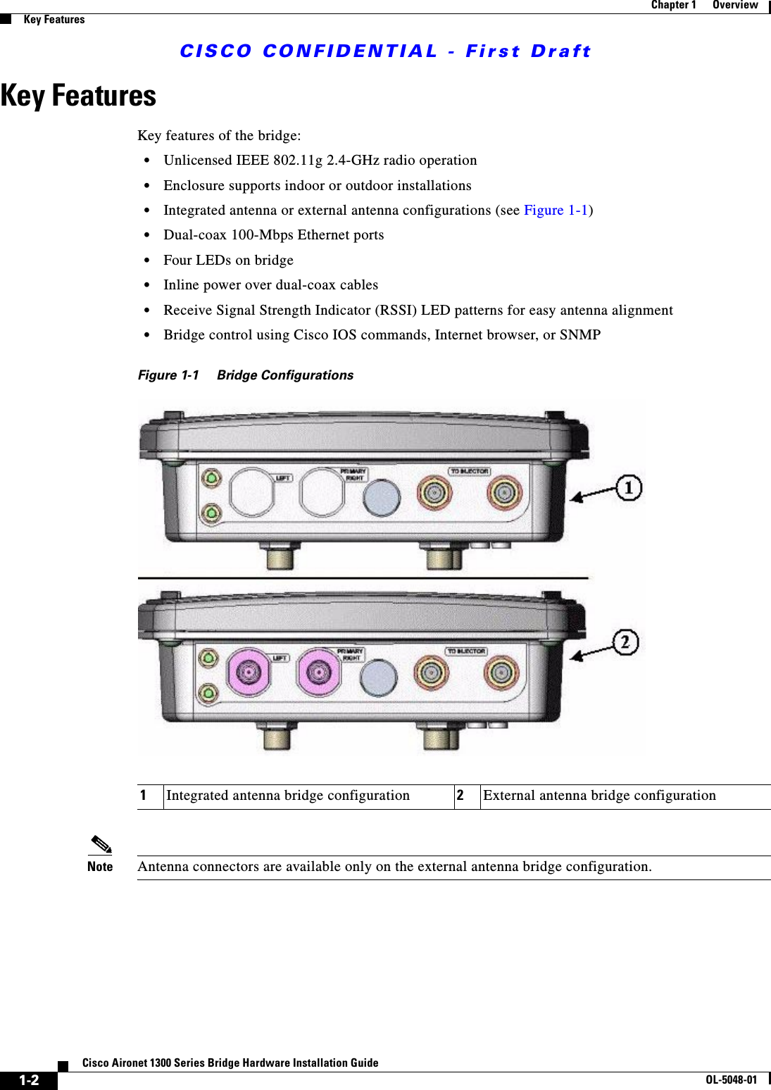
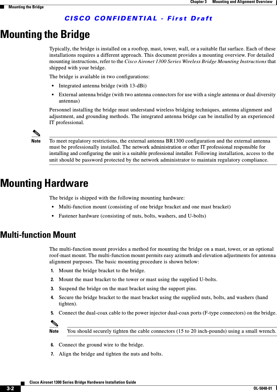
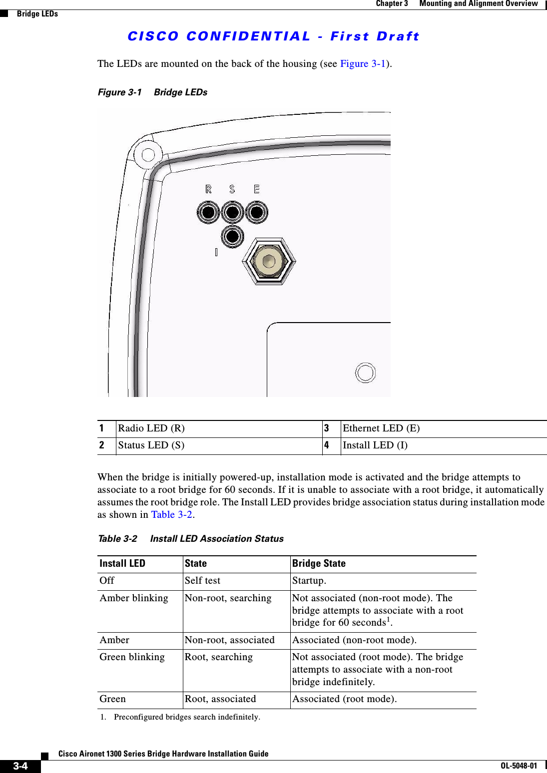
Cisco Systems 102052P 802.11g Mini PCI Modular Transmitter User Manual 1300Higb
Cisco Systems Inc 802.11g Mini PCI Modular Transmitter 1300Higb
UserManual.wiki
>
Cisco Systems
>
102052P User Manual
Users Manual
Navigation menu
Upload a User Manual
Namespaces
Wiki Guide
HTML
PDF
Info
Views
User Manual
Discussion / Help
Navigation

![CISCO CONFIDENTIAL - First DraftxiCisco Aironet 1300 Series Bridge Hardware Installation GuideOL-5048-01PrefaceRelated PublicationsRelated PublicationsFor more information about bridges and related products, refer to the following publications:•Quick Start Guide: Cisco Aironet 1300 Series Bridge describes the bridge, system components, and how to obtain bridge documentation. This document is included in the shipping box with your bridge.•Cisco IOS Software Configuration Guide for Cisco Aironet Bridges describes the bridge’s management system and explains how to configure the bridge. This document is available on the Cisco CCO web site at the following URL:http://www.cisco.com/univercd/cc/td/doc/product/wireless/index.htm•Cisco Aironet 1400 Series Wireless Bridge Mounting Instructions that was shipped with your bridge provides detailed instructions for mounting the bridge and aligning the antenna.WarnungDieses Warnsymbol bedeutet Gefahr. Sie befinden sich in einer Situation, die zu einer Körperverletzung führen könnte. Bevor Sie mit der Arbeit an irgendeinem Gerät beginnen, seien Sie sich der mit elektrischen Stromkreisen verbundenen Gefahren und der Standardpraktiken zur Vermeidung von Unfällen bewußt. (Übersetzungen der in dieser Veröffentlichung enthaltenen Warnhinweise finden Sie im Anhang mit dem Titel “Translated Safety Warnings” (Übersetzung der Warnhinweise).)AvvertenzaQuesto simbolo di avvertenza indica un pericolo. Si è in una situazione che può causare infortuni. Prima di lavorare su qualsiasi apparecchiatura, occorre conoscere i pericoli relativi ai circuiti elettrici ed essere al corrente delle pratiche standard per la prevenzione di incidenti. La traduzione delle avvertenze riportate in questa pubblicazione si trova nell’appendice, “Translated Safety Warnings” (Traduzione delle avvertenze di sicurezza).AdvarselDette varselsymbolet betyr fare. Du befinner deg i en situasjon som kan føre til personskade. Før du utfører arbeid på utstyr, må du være oppmerksom på de faremomentene som elektriske kretser innebærer, samt gjøre deg kjent med vanlig praksis når det gjelder å unngå ulykker. (Hvis du vil se oversettelser av de advarslene som finnes i denne publikasjonen, kan du se i vedlegget "Translated Safety Warnings" [Oversatte sikkerhetsadvarsler].)AvisoEste símbolo de aviso indica perigo. Encontra-se numa situação que lhe poderá causar danos fisicos. Antes de começar a trabalhar com qualquer equipamento, familiarize-se com os perigos relacionados com circuitos eléctricos, e com quaisquer práticas comuns que possam prevenir possíveis acidentes. (Para ver as traduções dos avisos que constam desta publicação, consulte o apêndice “Translated Safety Warnings” - “Traduções dos Avisos de Segurança”).¡Advertencia!Este símbolo de aviso significa peligro. Existe riesgo para su integridad física. Antes de manipular cualquier equipo, considerar los riesgos que entraña la corriente eléctrica y familiarizarse con los procedimientos estándar de prevención de accidentes. (Para ver traducciones de las advertencias que aparecen en esta publicación, consultar el apéndice titulado “Translated Safety Warnings.”)Varning!Denna varningssymbol signalerar fara. Du befinner dig i en situation som kan leda till personskada. Innan du utför arbete på någon utrustning måste du vara medveten om farorna med elkretsar och känna till vanligt förfarande för att förebygga skador. (Se förklaringar av de varningar som förekommer i denna publikation i appendix "Translated Safety Warnings" [Översatta säkerhetsvarningar].)](https://usermanual.wiki/Cisco-Systems/102052P/User-Guide-390753-Page-11.png)
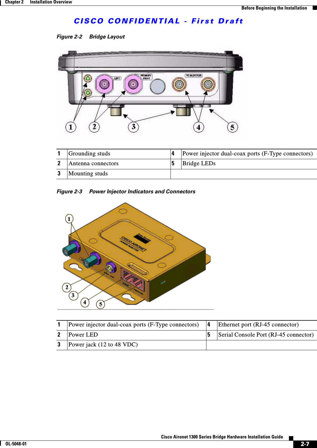
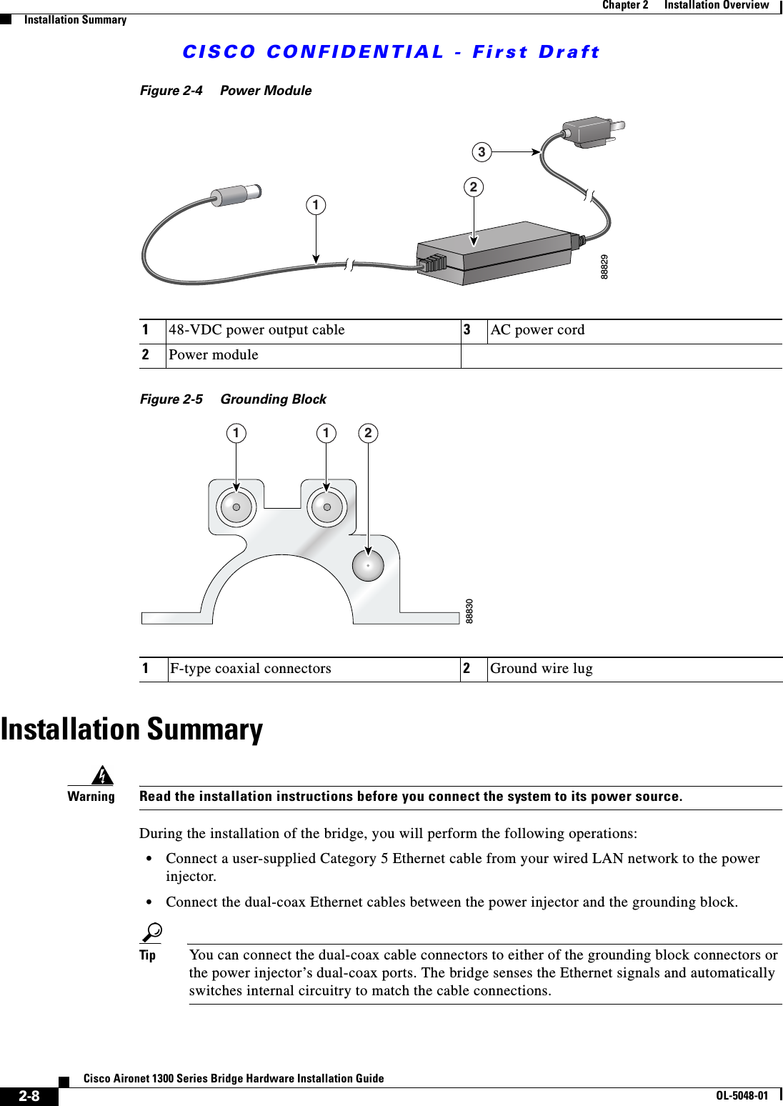
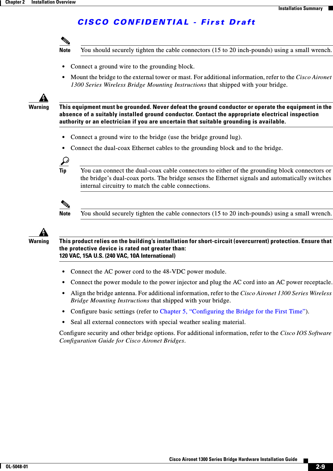
![CISCO CONFIDENTIAL - First Draft2-6Cisco Aironet 1300 Series Bridge Hardware Installation GuideOL-5048-01Chapter 2 Installation OverviewBefore Beginning the InstallationPackage ContentsEach bridge package contains the following items:•Bridge unit•Power injector unit (with mounting screws and wall anchors)•Power module and AC power cord (with mounting screws and wall anchors)•Two dual-coax cables [20 ft (6.1 m) and 50 ft (15.2 m)]•Mounting kit and hardware –Multi-function mount (consisting of two bridge brackets and one tower or mast bracket) –Two tower clamps (U-bolts) with four nuts and washers–Four bolts, lock washers, and washers for securing the bridge brackets to the tower or mast bracket–Four bolts and lock washers for securing the bridge brackets to the bridge•Grounding block and mounting screws•Ground lug for the bridge with screws•Weatherproofing kit (consisting of Coax Seal and electrical joint compound)•Quick Start Guide: Cisco Aironet 1300 Series Wireless Bridge•Cisco Aironet 1300 Series Wireless Bridge Mounting Instructions•Cisco product registration and Cisco documentation feedback cardsBefore Beginning the InstallationBefore you begin the installation process, please carefully review the following list of figures to become familiar with the system components, connectors, indicators, cables, system interconnection, and grounding:•Bridge Installation diagram (Figure 2-1)•Bridge layout (Figure 2-2)•Power injector layout (Figure 2-3)•Power module (Figure 2-4)•Grounding block (Figure 2-5) Note To meet regulatory restrictions, the external antenna BR1300 configuration and the external antenna must be professionally installed. The network administration or other IT professional responsible for installing and configuring the unit is a suitable professional installer. Following installation, access to the unit should be password protected by the network administrator to maintain regulatory compliance.](https://usermanual.wiki/Cisco-Systems/102052P/User-Guide-390753-Page-30.png)


![CISCO CONFIDENTIAL - First Draft7-5Cisco Aironet 1300 Series Bridge Hardware Installation GuideOL-5048-01Chapter 7 Using the Command-Line InterfaceUsing Command HistoryChanging the Command History Buffer SizeBy default, the access point records ten command lines in its history buffer. Beginning in privileged EXEC mode, enter this command to change the number of command lines that the access point records during the current terminal session: ap# terminal history [size number-of-lines]The range is from 0 to 256.Beginning in line configuration mode, enter this command to configure the number of command lines the access point records for all sessions on a particular line:ap(config-line)# history [size number-of-lines]The range is from 0 to 256.Recalling CommandsTo recall commands from the history buffer, perform one of the actions listed in Table 7-4:Disabling the Command History FeatureThe command history feature is automatically enabled. To disable the feature during the current terminal session, enter the terminal no history privileged EXEC command. To disable command history for the line, enter the no history line configuration command.Table 7-4 Recalling CommandsAction11. The arrow keys function only on ANSI-compatible terminals such as VT100s.ResultPress Ctrl-P or the up arrow key. Recall commands in the history buffer, beginning with the most recent command. Repeat the key sequence to recall successively older commands.Press Ctrl-N or the down arrow key. Return to more recent commands in the history buffer after recalling commands with Ctrl-P or the up arrow key. Repeat the key sequence to recall successively more recent commands. show history While in privileged EXEC mode, list the last several commands that you just entered. The number of commands that are displayed is determined by the setting of the terminal history global configuration command and history line configuration command.](https://usermanual.wiki/Cisco-Systems/102052P/User-Guide-390753-Page-69.png)
![CISCO CONFIDENTIAL - First DraftA-2Cisco Aironet 1300 Series Bridge Hardware Installation GuideOL-5048-01Appendix A Translated Safety WarningsStatement 84—Warning DefinitionStatement 84—Warning DefinitionWarningThis warning symbol means danger. You are in a situation that could cause bodily injury. Before you work on any equipment, be aware of the hazards involved with electrical circuitry and be familiar with standard practices for preventing accidents. (To see translations of the warnings that appear in this publication, refer to the appendix “Translated Safety Warnings.”)WaarschuwingDit waarschuwingssymbool betekent gevaar. U verkeert in een situatie die lichamelijk letsel kan veroorzaken. Voordat u aan enige apparatuur gaat werken, dient u zich bewust te zijn van de bij elektrische schakelingen betrokken risico’s en dient u op de hoogte te zijn van standaard maatregelen om ongelukken te voorkomen. (Voor vertalingen van de waarschuwingen die in deze publicatie verschijnen, kunt u het aanhangsel “Translated Safety Warnings” (Vertalingen van veiligheidsvoorschriften) raadplegen.)VaroitusTämä varoitusmerkki merkitsee vaaraa. Olet tilanteessa, joka voi johtaa ruumiinvammaan. Ennen kuin työskentelet minkään laitteiston parissa, ota selvää sähkökytkentöihin liittyvistä vaaroista ja tavanomaisista onnettomuuksien ehkäisykeinoista. (Tässä julkaisussa esiintyvien varoitusten käännökset löydät liitteestä "Translated Safety Warnings" (käännetyt turvallisuutta koskevat varoitukset).)AttentionCe symbole d’avertissement indique un danger. Vous vous trouvez dans une situation pouvant entraîner des blessures. Avant d’accéder à cet équipement, soyez conscient des dangers posés par les circuits électriques et familiarisez-vous avec les procédures courantes de prévention des accidents. Pour obtenir les traductions des mises en garde figurant dans cette publication, veuillez consulter l’annexe intitulée « Translated Safety Warnings » (Traduction des avis de sécurité).WarnungDieses Warnsymbol bedeutet Gefahr. Sie befinden sich in einer Situation, die zu einer Körperverletzung führen könnte. Bevor Sie mit der Arbeit an irgendeinem Gerät beginnen, seien Sie sich der mit elektrischen Stromkreisen verbundenen Gefahren und der Standardpraktiken zur Vermeidung von Unfällen bewußt. (Übersetzungen der in dieser Veröffentlichung enthaltenen Warnhinweise finden Sie im Anhang mit dem Titel “Translated Safety Warnings” (Übersetzung der Warnhinweise).)AvvertenzaQuesto simbolo di avvertenza indica un pericolo. Si è in una situazione che può causare infortuni. Prima di lavorare su qualsiasi apparecchiatura, occorre conoscere i pericoli relativi ai circuiti elettrici ed essere al corrente delle pratiche standard per la prevenzione di incidenti. La traduzione delle avvertenze riportate in questa pubblicazione si trova nell’appendice, “Translated Safety Warnings” (Traduzione delle avvertenze di sicurezza).AdvarselDette varselsymbolet betyr fare. Du befinner deg i en situasjon som kan føre til personskade. Før du utfører arbeid på utstyr, må du være oppmerksom på de faremomentene som elektriske kretser innebærer, samt gjøre deg kjent med vanlig praksis når det gjelder å unngå ulykker. (Hvis du vil se oversettelser av de advarslene som finnes i denne publikasjonen, kan du se i vedlegget "Translated Safety Warnings" [Oversatte sikkerhetsadvarsler].)](https://usermanual.wiki/Cisco-Systems/102052P/User-Guide-390753-Page-86.png)
![CISCO CONFIDENTIAL - First DraftA-3Cisco Aironet 1300 Series Bridge Hardware Installation GuideOL-5048-01Appendix A Translated Safety WarningsStatement 245B—Explosive Device Proximity WarningStatement 245B—Explosive Device Proximity WarningAvisoEste símbolo de aviso indica perigo. Encontra-se numa situação que lhe poderá causar danos fisicos. Antes de começar a trabalhar com qualquer equipamento, familiarize-se com os perigos relacionados com circuitos eléctricos, e com quaisquer práticas comuns que possam prevenir possíveis acidentes. (Para ver as traduções dos avisos que constam desta publicação, consulte o apêndice “Translated Safety Warnings” - “Traduções dos Avisos de Segurança”).¡Advertencia!Este símbolo de aviso significa peligro. Existe riesgo para su integridad física. Antes de manipular cualquier equipo, considerar los riesgos que entraña la corriente eléctrica y familiarizarse con los procedimientos estándar de prevención de accidentes. (Para ver traducciones de las advertencias que aparecen en esta publicación, consultar el apéndice titulado “Translated Safety Warnings.”)Varning!Denna varningssymbol signalerar fara. Du befinner dig i en situation som kan leda till personskada. Innan du utför arbete på någon utrustning måste du vara medveten om farorna med elkretsar och känna till vanligt förfarande för att förebygga skador. (Se förklaringar av de varningar som förekommer i denna publikation i appendix "Translated Safety Warnings" [Översatta säkerhetsvarningar].)WarningDo not operate your wireless network device near unshielded blasting caps or in an explosive environment unless the device has been modified to be especially qualified for such use. Statement 245BWaarschuwingGebruik dit draadloos netwerkapparaat alleen in de buurt van onbeschermde ontstekers of in een omgeving met explosieven indien het apparaat speciaal is aangepast om aan de eisen voor een dergelijk gebruik te voldoen.VaroitusÄlä käytä johdotonta verkkolaitetta suojaamattomien räjäytysnallien läheisyydessä tai räjäytysalueella, jos laitetta ei ole erityisesti muunnettu sopivaksi sellaiseen käyttöön.oen. AttentionNe jamais utiliser un équipement de réseau sans fil à proximité d'un détonateur non blindé ou dans un lieu présentant des risques d'explosion, sauf si l'équipement a été modifié à cet effet.WarnungBenutzen Sie Ihr drahtloses Netzwerkgerät nicht in der Nähe ungeschützter Sprengkapseln oder anderer explosiver Stoffe, es sei denn, Ihr Gerät wurde eigens für diesen Gebrauch modifiziert und bestimmt.AvvertenzaNon utilizzare la periferica di rete senza fili in prossimità di un detonatore non protetto o di esplosivi a meno che la periferica non sia stata modificata a tale proposito.AdvarselIkke bruk den trådløse nettverksenheten nært inntil uisolerte fenghetter eller i et eksplosivt miljø med mindre enheten er modifisert slik at den tåler slik bruk.](https://usermanual.wiki/Cisco-Systems/102052P/User-Guide-390753-Page-87.png)