Cisco Systems 102053 802.11a Cardbus radio module User Manual AP1200 Installation and Configu
Cisco Systems Inc 802.11a Cardbus radio module AP1200 Installation and Configu
Contents
- 1. User Manual
- 2. CRN 27004 Question 6 AP user manual
CRN 27004 Question 6 AP user manual


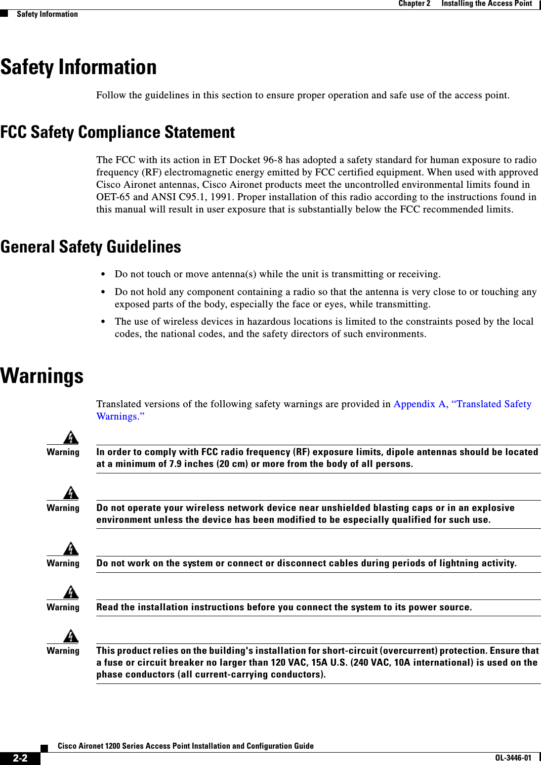
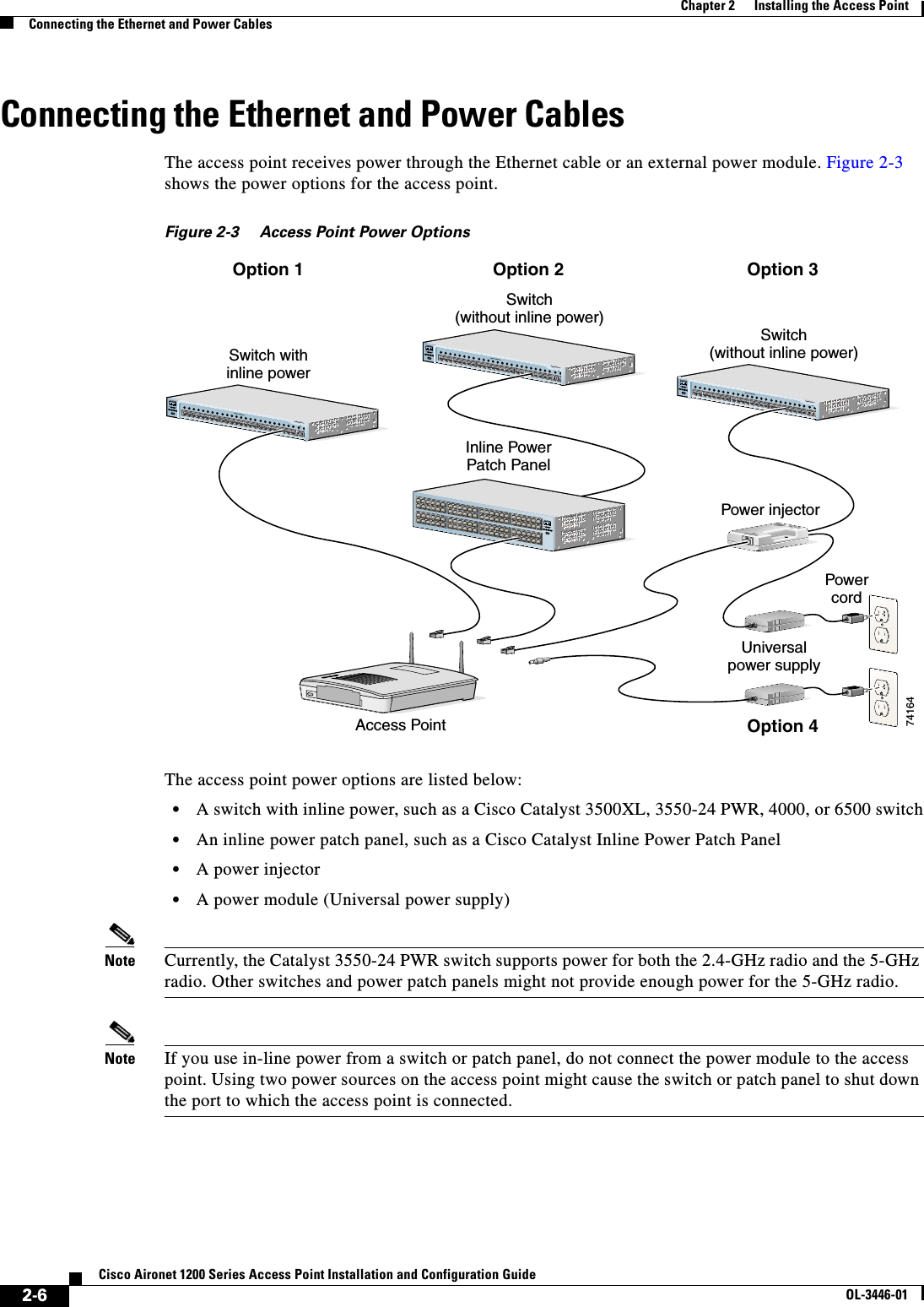
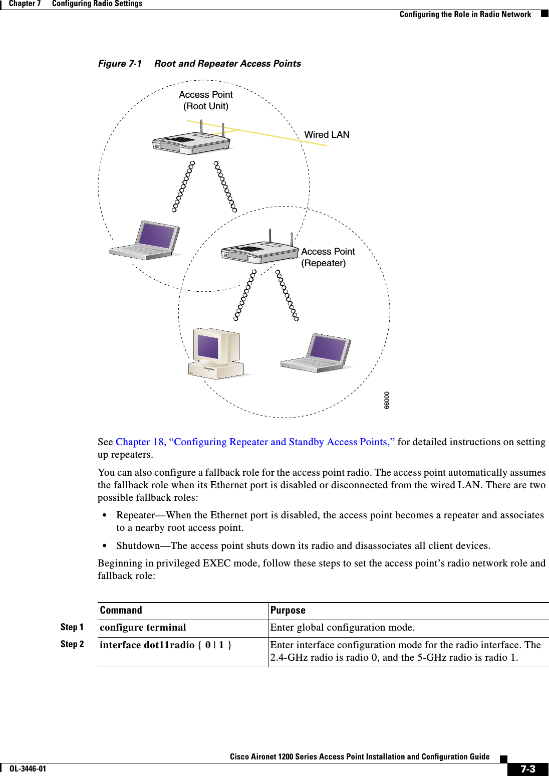
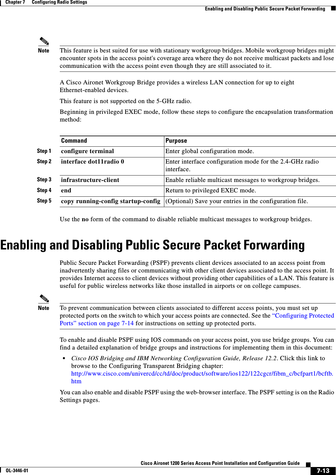
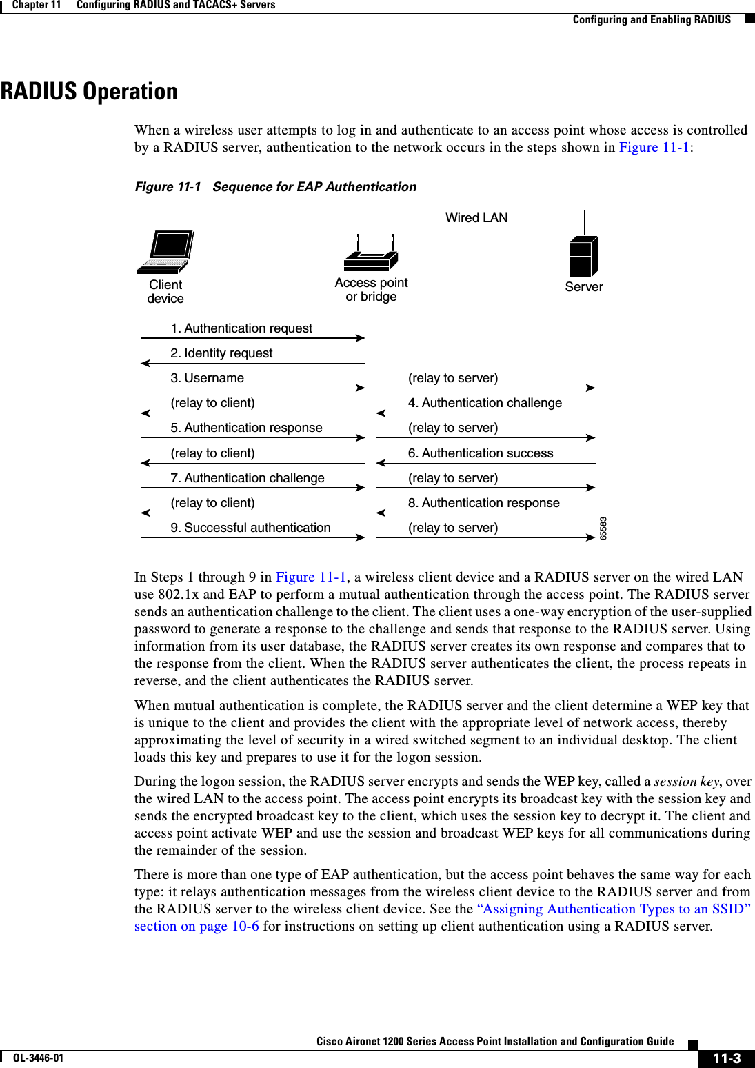
![xixCisco Aironet 1200 Series Access Point Installation and Configuration GuideOL-3446-01PrefaceConventionsChapter 23, “5-GHz Radio Module Upgrade,” provides instructions for upgrading the access point 5-GHz radio.Appendix A, “Translated Safety Warnings,” provides translations of the safety warnings that appear in this publication.Appendix B, “Declarations of Conformity and Regulatory Information,” provides declarations of conformity and regulatory information for the access point.Appendix C, “Channels and Antenna Settings,” lists the access point radio channels and the maximum power levels supported by the world’s regulatory domains.Appendix D, “Mounting Instructions,” describes how to mount the access point on a desktop, wall, or ceiling.Appendix E, “Protocol Filters,” lists some of the protocols that you can filter on the access point. Appendix F, “Supported MIBs,” lists the Simple Network Management Protocol (SNMP) Management Information Bases (MIBs) that the access point supports for this software release.Appendix G, “Access Point Specifications,” lists technical specifications for the access point.Appendix H, “Error and Event Messages,” lists the CLI error and event messages and provides an explanation and recommended action for each message.Appendix I, “Console Cable Pinouts,” identifies the pinouts for the serial console cable that connects to the access point’s serial console port. ConventionsThis publication uses these conventions to convey instructions and information:Command descriptions use these conventions:•Commands and keywords are in boldface text.•Arguments for which you supply values are in italic.•Square brackets ([ ]) mean optional elements.•Braces ({ }) group required choices, and vertical bars ( | ) separate the alternative elements.•Braces and vertical bars within square brackets ([{ | }]) mean a required choice within an optional element.Interactive examples use these conventions:•Terminal sessions and system displays are in screen font.•Information you enter is in boldface screen font.•Nonprinting characters, such as passwords or tabs, are in angle brackets (< >).Notes, cautions, and timesavers use these conventions and symbols:Tip Means the following will help you solve a problem. The tips information might not be troubleshooting or even an action, but could be useful information.Note Means reader take note. Notes contain helpful suggestions or references to materials not contained in this manual.](https://usermanual.wiki/Cisco-Systems/102053.CRN-27004-Question-6-AP-user-manual/User-Guide-441628-Page-19.png)
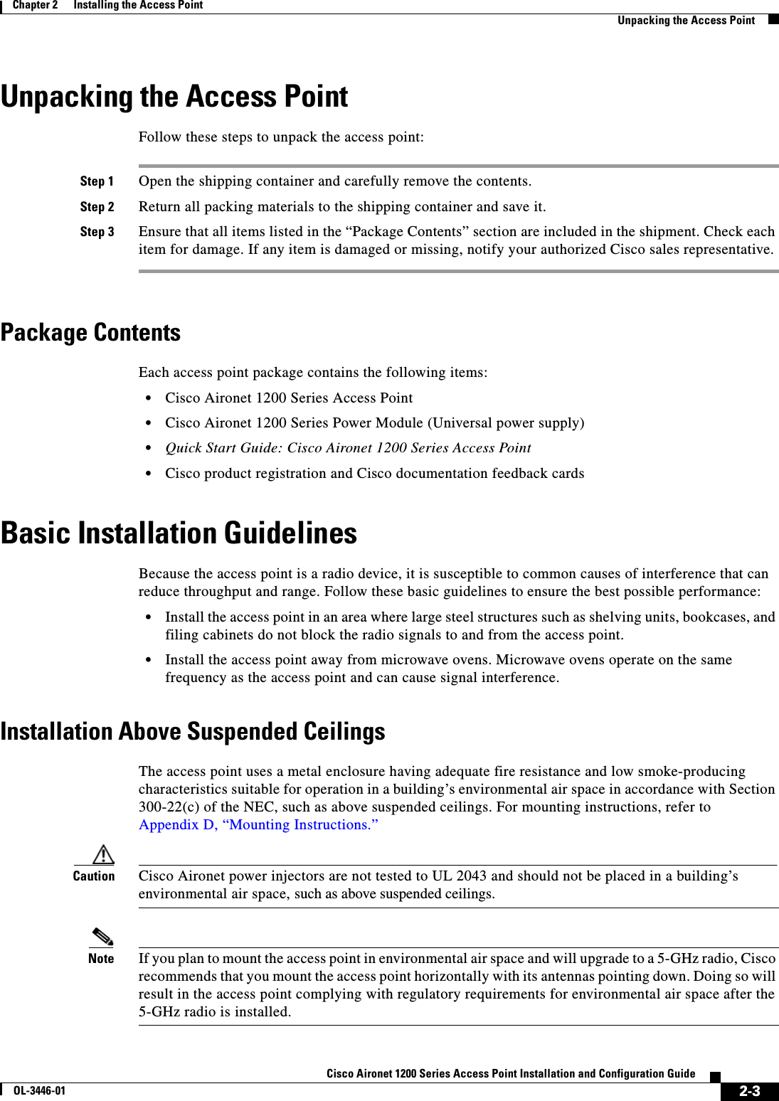
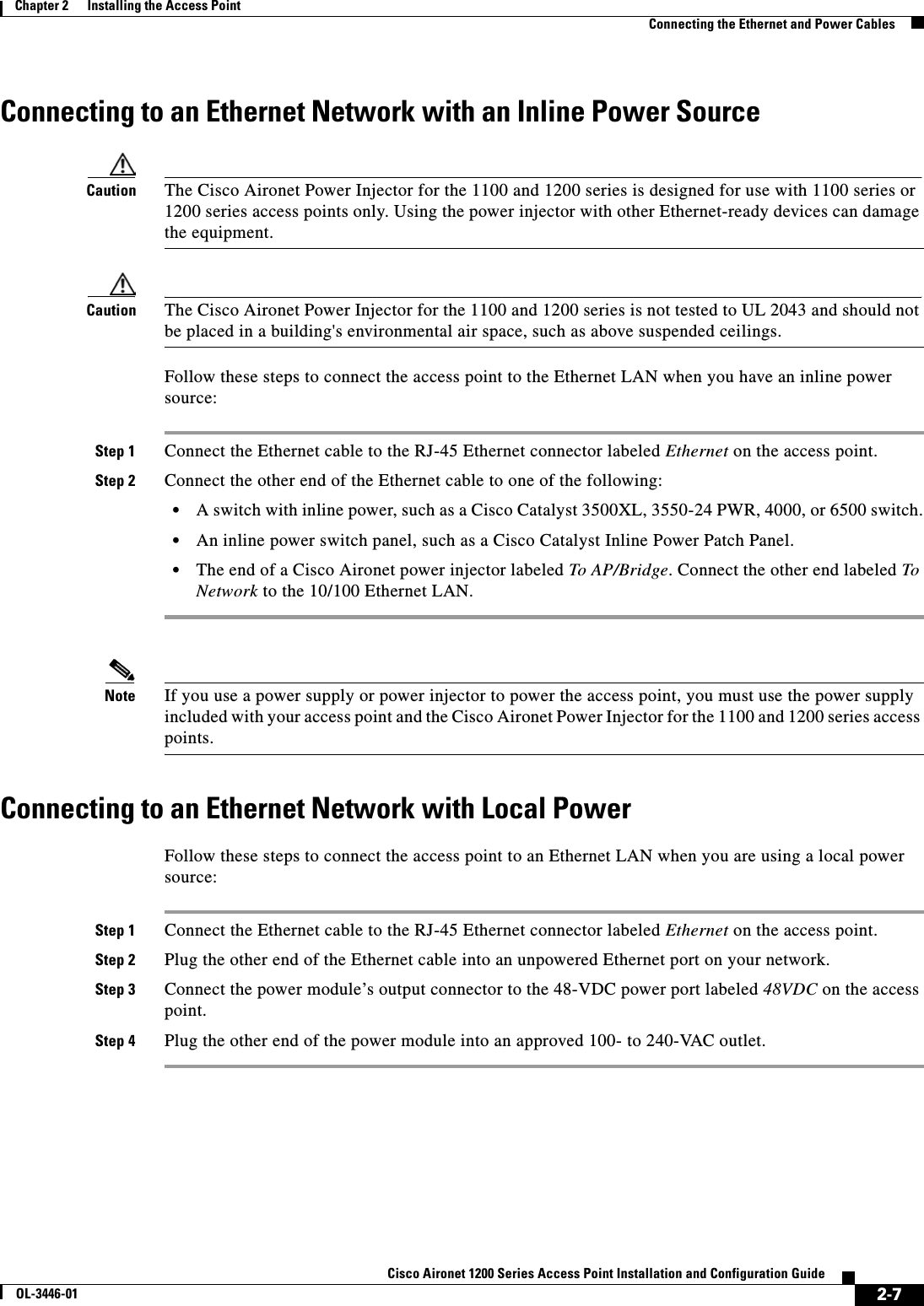
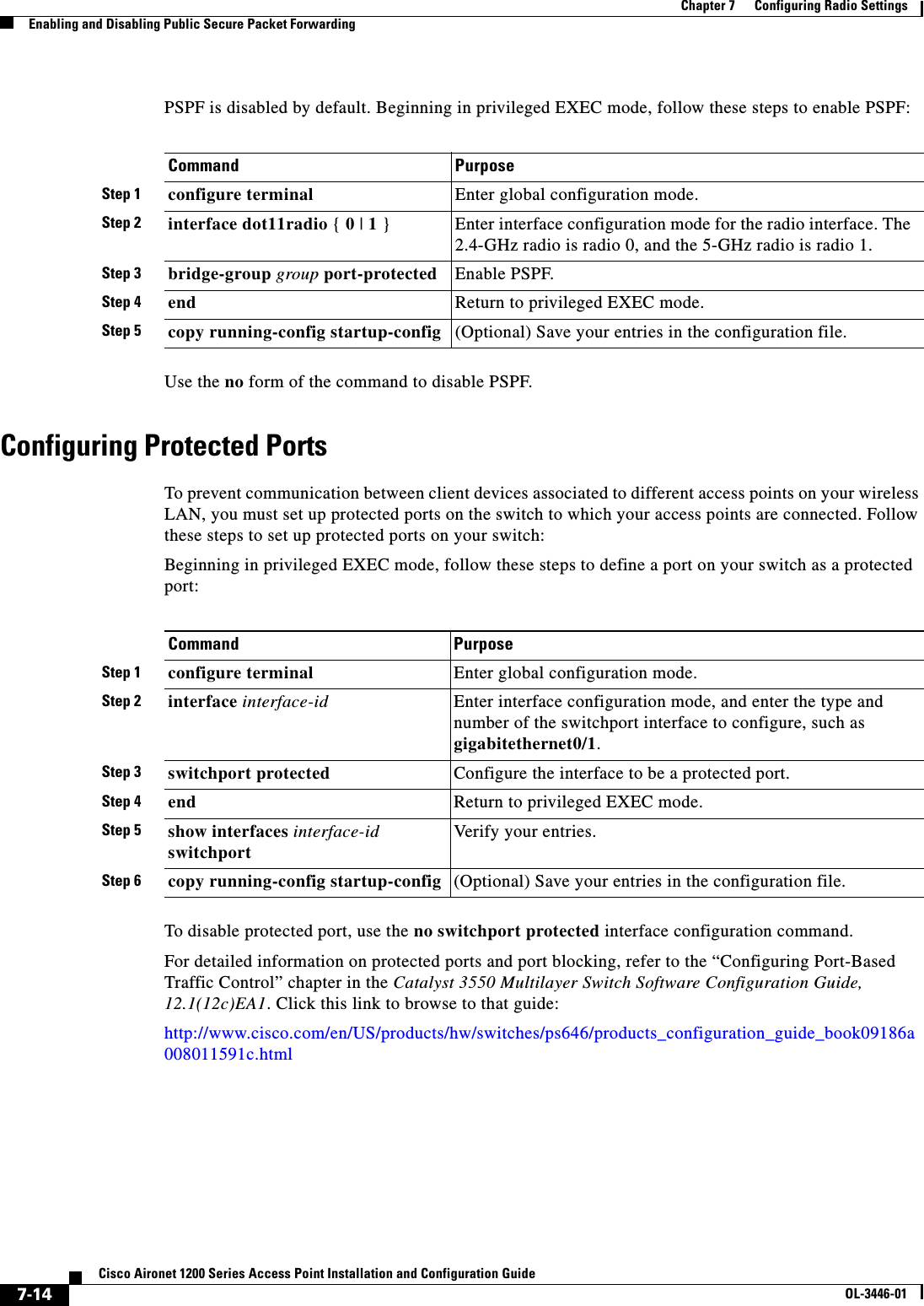
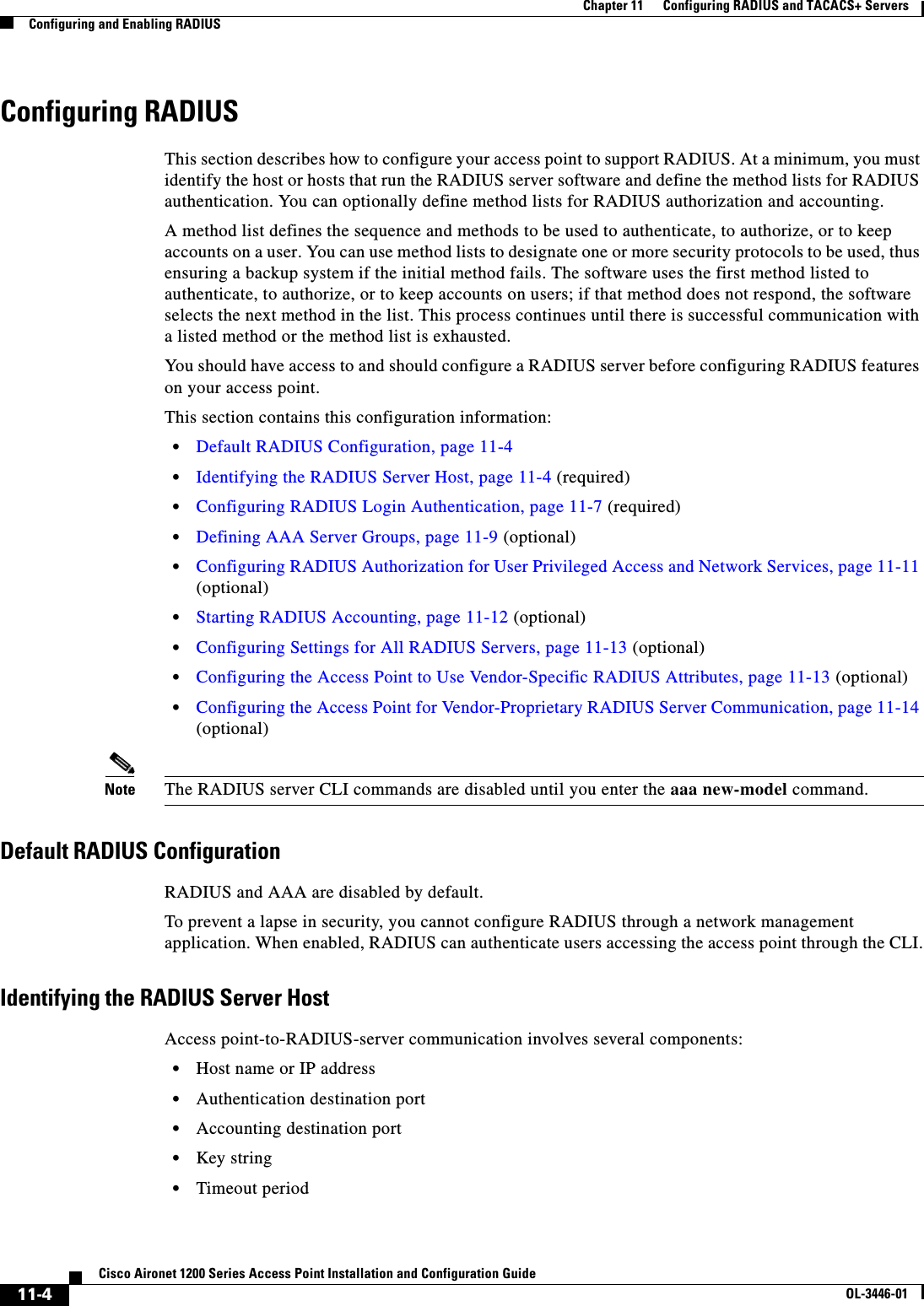
![xxCisco Aironet 1200 Series Access Point Installation and Configuration GuideOL-3446-01PrefaceConventionsCaution Means reader be careful. In this situation, you might do something that could result equipment damage or loss of data.WarningThis warning symbol means danger. You are in a situation that could cause bodily injury. Before you work on any equipment, be aware of the hazards involved with electrical circuitry and be familiar with standard practices for preventing accidents. (To see translations of the warnings that appear in this publication, refer to the appendix “Translated Safety Warnings.”)WaarschuwingDit waarschuwingssymbool betekent gevaar. U verkeert in een situatie die lichamelijk letsel kan veroorzaken. Voordat u aan enige apparatuur gaat werken, dient u zich bewust te zijn van de bij elektrische schakelingen betrokken risico’s en dient u op de hoogte te zijn van standaard maatregelen om ongelukken te voorkomen. (Voor vertalingen van de waarschuwingen die in deze publicatie verschijnen, kunt u het aanhangsel “Translated Safety Warnings” (Vertalingen van veiligheidsvoorschriften) raadplegen.)VaroitusTämä varoitusmerkki merkitsee vaaraa. Olet tilanteessa, joka voi johtaa ruumiinvammaan. Ennen kuin työskentelet minkään laitteiston parissa, ota selvää sähkökytkentöihin liittyvistä vaaroista ja tavanomaisista onnettomuuksien ehkäisykeinoista. (Tässä julkaisussa esiintyvien varoitusten käännökset löydät liitteestä "Translated Safety Warnings" (käännetyt turvallisuutta koskevat varoitukset).)AttentionCe symbole d’avertissement indique un danger. Vous vous trouvez dans une situation pouvant entraîner des blessures. Avant d’accéder à cet équipement, soyez conscient des dangers posés par les circuits électriques et familiarisez-vous avec les procédures courantes de prévention des accidents. Pour obtenir les traductions des mises en garde figurant dans cette publication, veuillez consulter l’annexe intitulée « Translated Safety Warnings » (Traduction des avis de sécurité).WarnungDieses Warnsymbol bedeutet Gefahr. Sie befinden sich in einer Situation, die zu einer Körperverletzung führen könnte. Bevor Sie mit der Arbeit an irgendeinem Gerät beginnen, seien Sie sich der mit elektrischen Stromkreisen verbundenen Gefahren und der Standardpraktiken zur Vermeidung von Unfällen bewußt. (Übersetzungen der in dieser Veröffentlichung enthaltenen Warnhinweise finden Sie im Anhang mit dem Titel “Translated Safety Warnings” (Übersetzung der Warnhinweise).)AvvertenzaQuesto simbolo di avvertenza indica un pericolo. Si è in una situazione che può causare infortuni. Prima di lavorare su qualsiasi apparecchiatura, occorre conoscere i pericoli relativi ai circuiti elettrici ed essere al corrente delle pratiche standard per la prevenzione di incidenti. La traduzione delle avvertenze riportate in questa pubblicazione si trova nell’appendice, “Translated Safety Warnings” (Traduzione delle avvertenze di sicurezza).AdvarselDette varselsymbolet betyr fare. Du befinner deg i en situasjon som kan føre til personskade. Før du utfører arbeid på utstyr, må du være oppmerksom på de faremomentene som elektriske kretser innebærer, samt gjøre deg kjent med vanlig praksis når det gjelder å unngå ulykker. (Hvis du vil se oversettelser av de advarslene som finnes i denne publikasjonen, kan du se i vedlegget "Translated Safety Warnings" [Oversatte sikkerhetsadvarsler].)](https://usermanual.wiki/Cisco-Systems/102053.CRN-27004-Question-6-AP-user-manual/User-Guide-441628-Page-20.png)
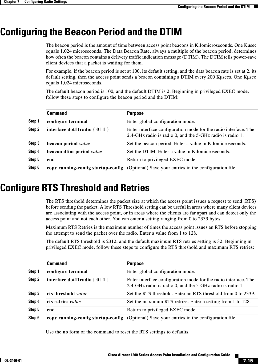
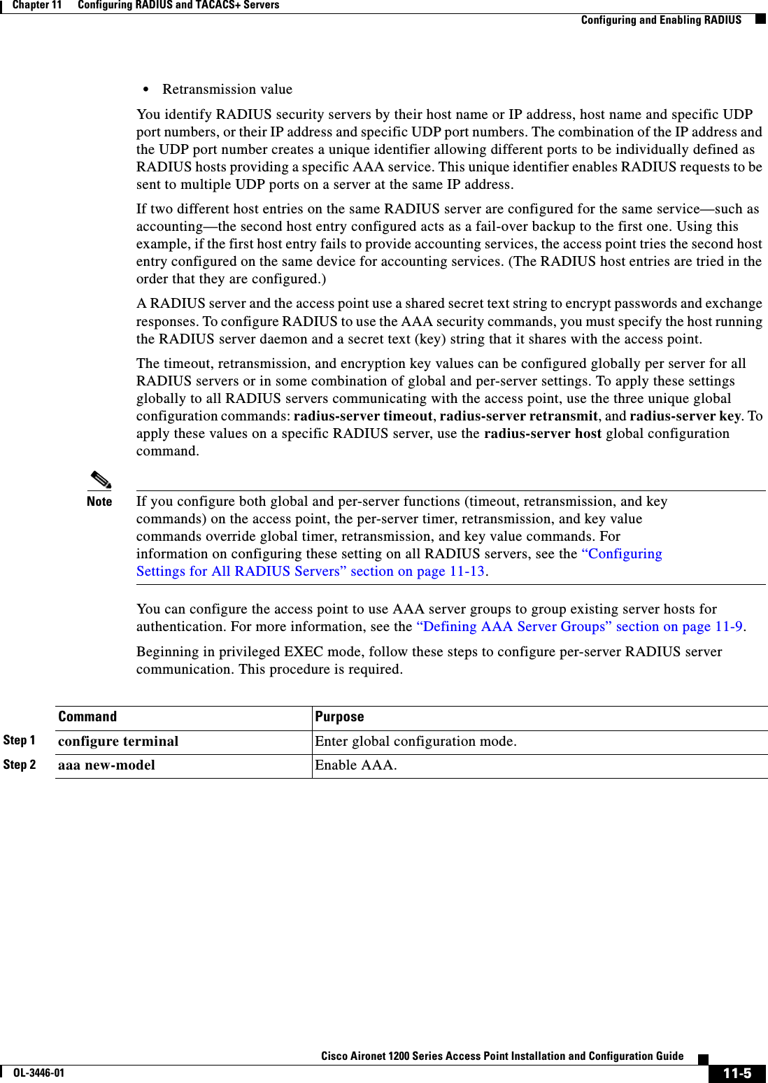
![xxiCisco Aironet 1200 Series Access Point Installation and Configuration GuideOL-3446-01PrefaceRelated PublicationsRelated PublicationsThese documents provide complete information about the access point:•Release Notes for 1200 Series Access Points•Cisco Aironet 1200 Series Access Point Command ReferenceClick this link to browse to the Cisco Aironet documentation home page:http://www.cisco.com/univercd/cc/td/doc/product/wireless/index.htmTo browse to the 1200 series access point documentation, select Aironet 1200 Series Wireless LAN Products > Cisco Aironet 1200 Series Access Points.Obtaining DocumentationCisco provides several ways to obtain documentation, technical assistance, and other technical resources. These sections explain how to obtain technical information from Cisco Systems.Cisco.comYou can access the most current Cisco documentation on the World Wide Web at this URL:http://www.cisco.com/univercd/home/home.htmYou can access the Cisco website at this URL:http://www.cisco.comInternational Cisco web sites can be accessed from this URL:http://www.cisco.com/public/countries_languages.shtmlAvisoEste símbolo de aviso indica perigo. Encontra-se numa situação que lhe poderá causar danos fisicos. Antes de começar a trabalhar com qualquer equipamento, familiarize-se com os perigos relacionados com circuitos eléctricos, e com quaisquer práticas comuns que possam prevenir possíveis acidentes. (Para ver as traduções dos avisos que constam desta publicação, consulte o apêndice “Translated Safety Warnings” - “Traduções dos Avisos de Segurança”).¡Advertencia!Este símbolo de aviso significa peligro. Existe riesgo para su integridad física. Antes de manipular cualquier equipo, considerar los riesgos que entraña la corriente eléctrica y familiarizarse con los procedimientos estándar de prevención de accidentes. (Para ver traducciones de las advertencias que aparecen en esta publicación, consultar el apéndice titulado “Translated Safety Warnings.”)Varning!Denna varningssymbol signalerar fara. Du befinner dig i en situation som kan leda till personskada. Innan du utför arbete på någon utrustning måste du vara medveten om farorna med elkretsar och känna till vanligt förfarande för att förebygga skador. (Se förklaringar av de varningar som förekommer i denna publikation i appendix "Translated Safety Warnings" [Översatta säkerhetsvarningar].)](https://usermanual.wiki/Cisco-Systems/102053.CRN-27004-Question-6-AP-user-manual/User-Guide-441628-Page-21.png)


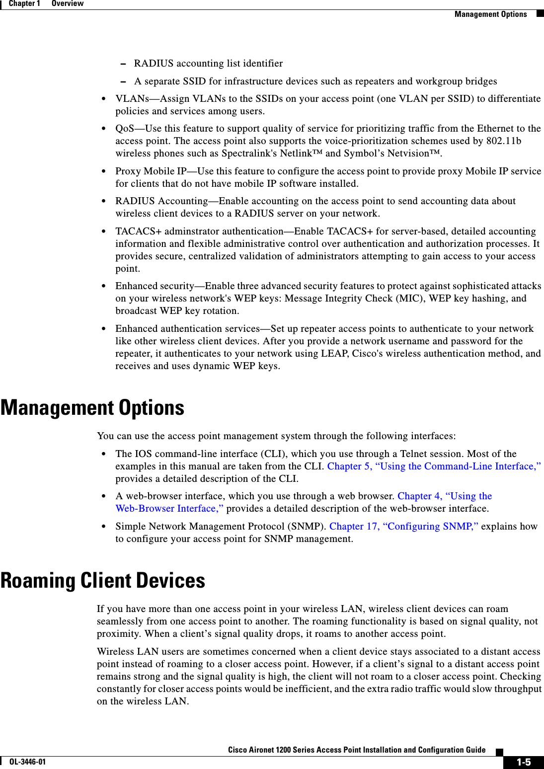
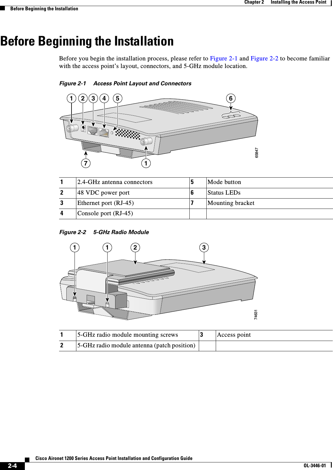

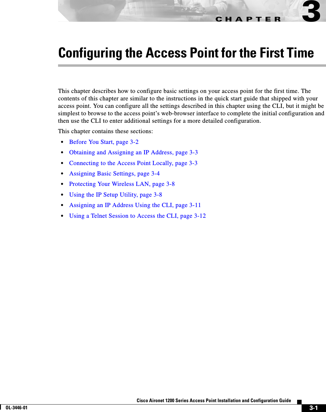
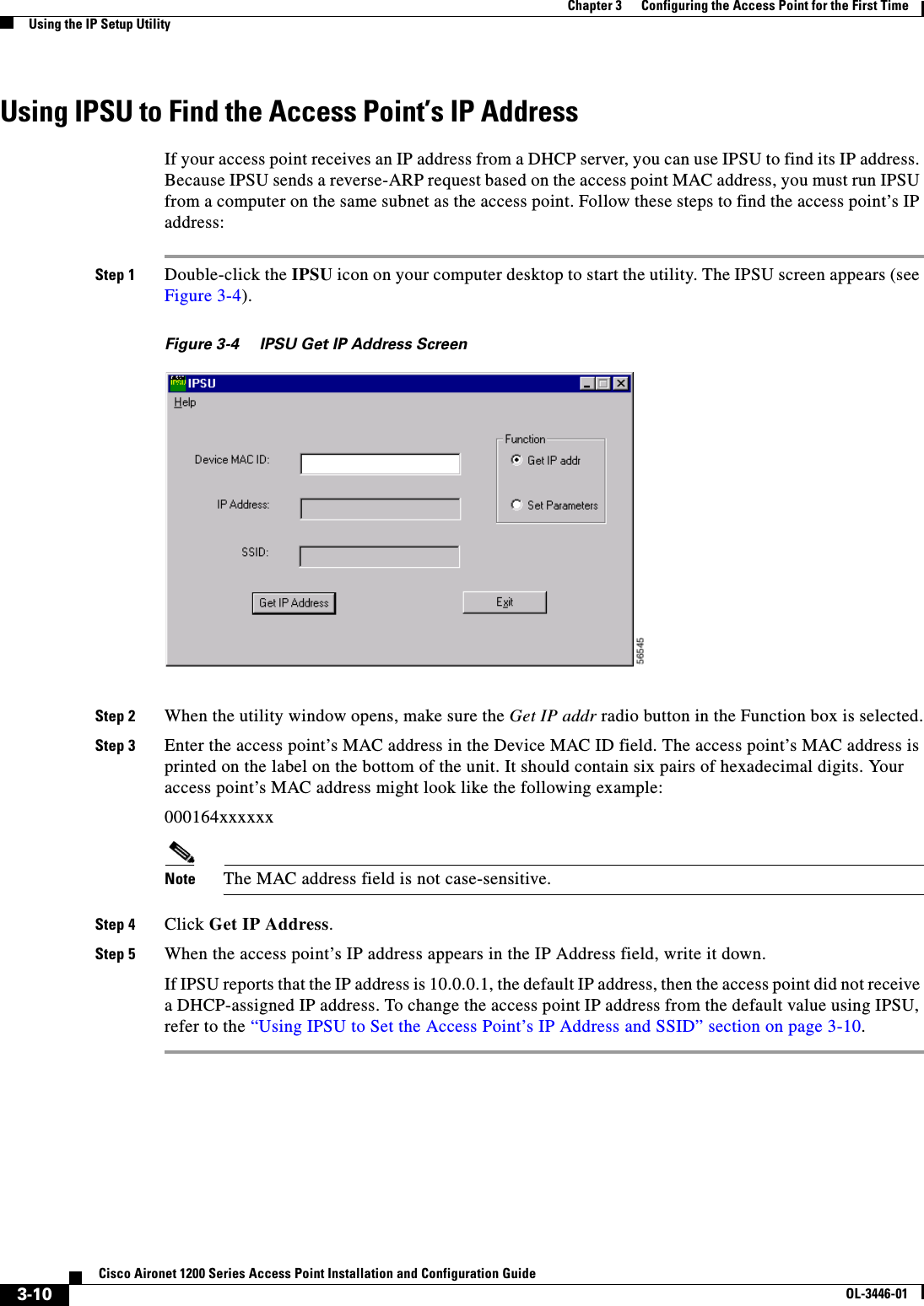

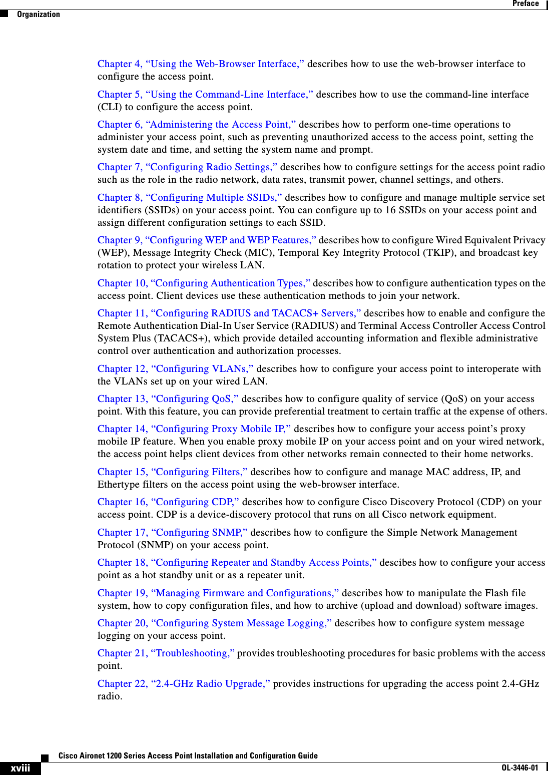
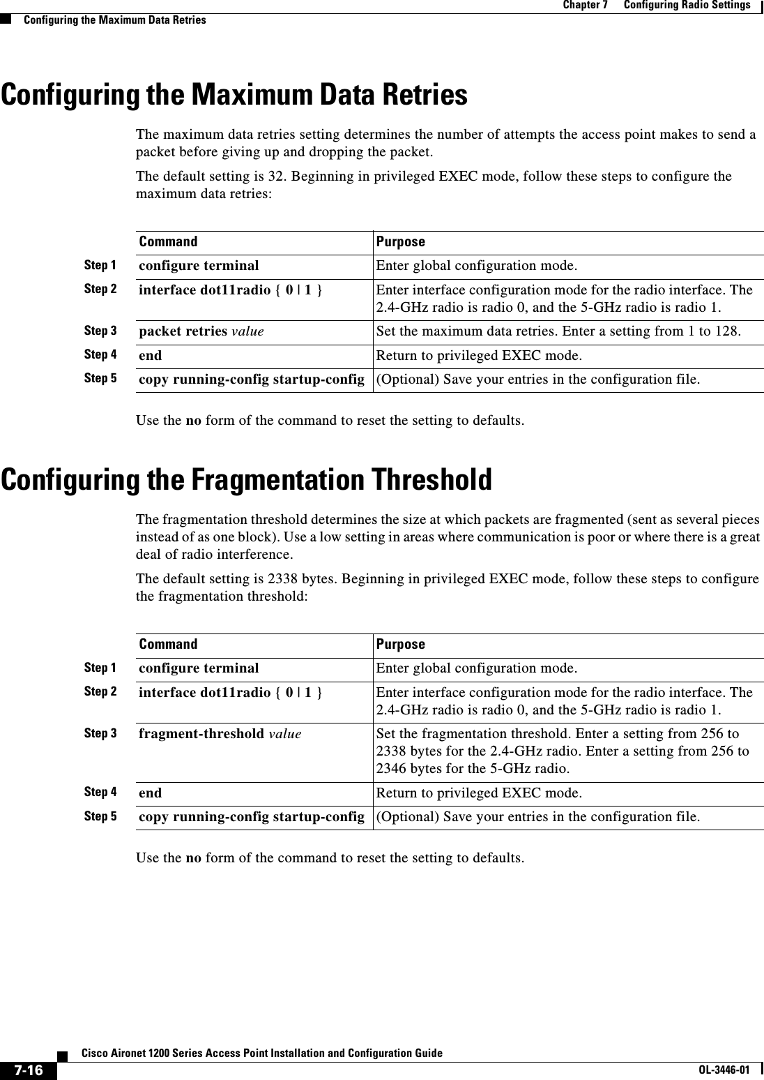
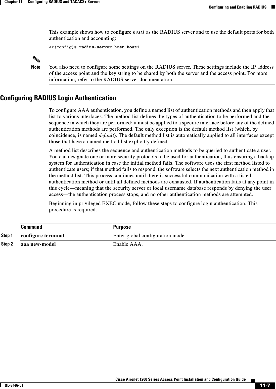
![5-4Cisco Aironet 1200 Series Access Point Installation and Configuration GuideOL-3446-01Chapter 5 Using the Command-Line InterfaceUnderstanding CLI MessagesConfiguration commands can also have a default form. The default form of a command returns the command setting to its default. Most commands are disabled by default, so the default form is the same as the no form. However, some commands are enabled by default and have variables set to certain default values. In these cases, the default command enables the command and sets variables to their default values.Understanding CLI MessagesTable 5-3 lists some error messages that you might encounter while using the CLI to configure your access point.Using Command HistoryThe IOS provides a history or record of commands that you have entered. This feature is particularly useful for recalling long or complex commands or entries, including access lists. You can customize the command history feature to suit your needs as described in these sections:•Changing the Command History Buffer Size, page 5-4•Recalling Commands, page 5-5•Disabling the Command History Feature, page 5-5Changing the Command History Buffer SizeBy default, the access point records ten command lines in its history buffer. Beginning in privileged EXEC mode, enter this command to change the number of command lines that the access point records during the current terminal session: ap# terminal history [sizenumber-of-lines]Table 5-3 Common CLI Error MessagesError Message Meaning How to Get Help% Ambiguous command: "show con"You did not enter enough characters for your access point to recognize the command.Re-enter the command followed by a question mark (?)with a space between the command and the question mark.The possible keywords that you can enter with the command are displayed.% Incomplete command. You did not enter all the keywords or values required by this command.Re-enter the command followed by a question mark (?)with a space between the command and the question mark.The possible keywords that you can enter with the command are displayed.% Invalid input detected at ‘^’ marker.You entered the command incorrectly. The caret (^) marks the point of the error.Enter a question mark (?) to display all the commands that are available in this command mode.The possible keywords that you can enter with the command are displayed.](https://usermanual.wiki/Cisco-Systems/102053.CRN-27004-Question-6-AP-user-manual/User-Guide-441628-Page-64.png)
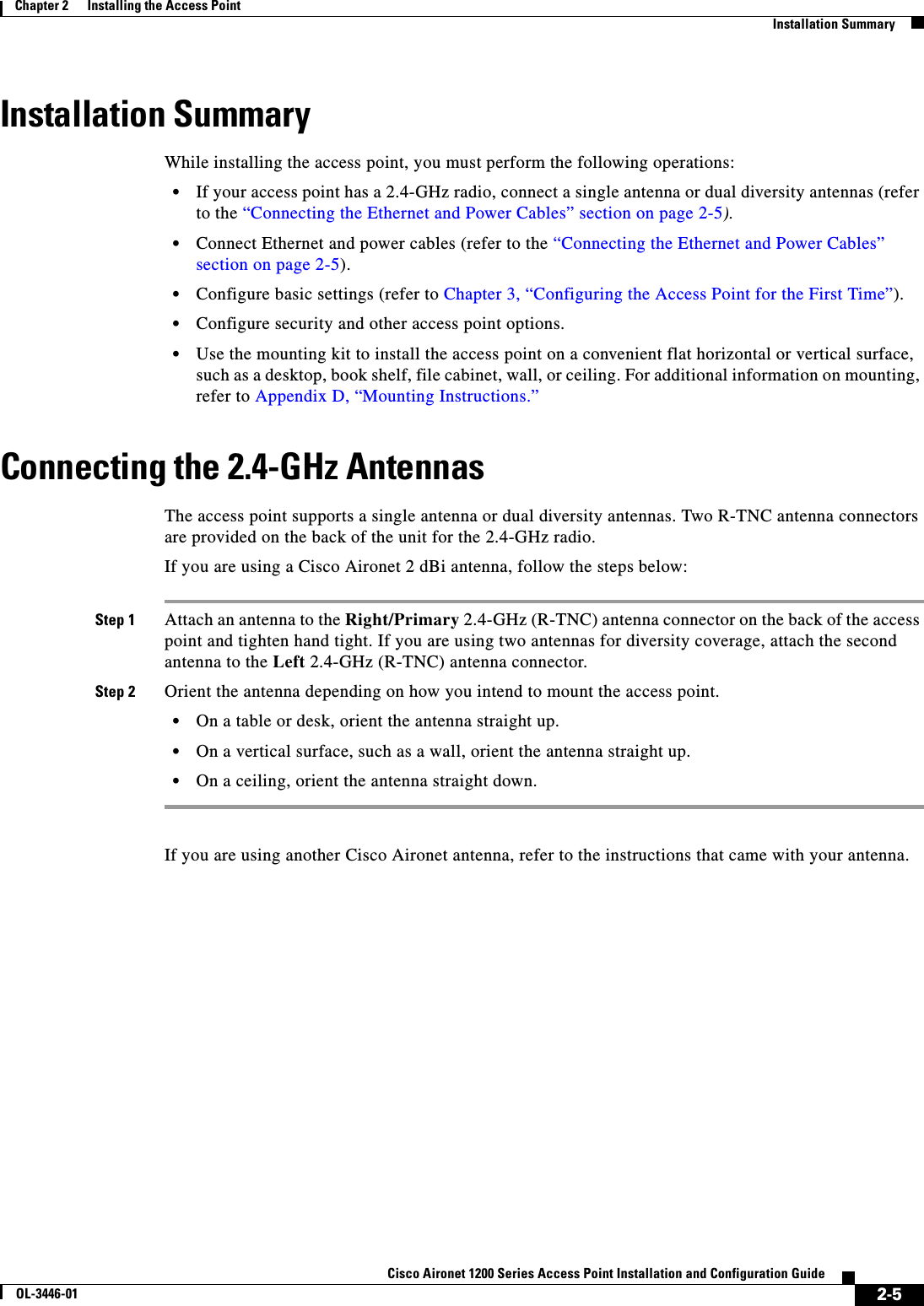
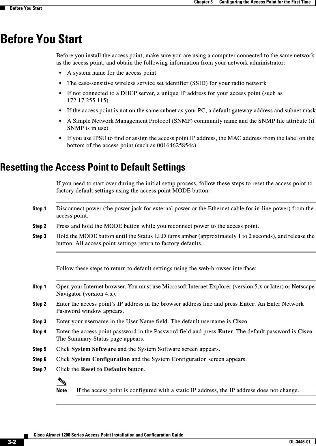
![5-5Cisco Aironet 1200 Series Access Point Installation and Configuration GuideOL-3446-01Chapter 5 Using the Command-Line InterfaceUsing Editing FeaturesThe range is from 0 to 256.Beginning in line configuration mode, enter this command to configure the number of command lines the access point records for all sessions on a particular line:ap(config-line)# history [sizenumber-of-lines]The range is from 0 to 256.Recalling CommandsTo recall commands from the history buffer, perform one of the actions listed in Table 5-4:Disabling the Command History FeatureThe command history feature is automatically enabled. To disable the feature during the current terminal session, enter the terminal no history privileged EXEC command. To disable command history for the line, enter the no history line configuration command.Using Editing FeaturesThis section describes the editing features that can help you manipulate the command line. It contains these sections:•Enabling and Disabling Editing Features, page 5-6•Editing Commands Through Keystrokes, page 5-6•Editing Command Lines that Wrap, page 5-7Table 5-4 Recalling CommandsAction11. The arrow keys function only on ANSI-compatible terminals such as VT100s.ResultPress Ctrl-P or the up arrow key. Recall commands in the history buffer, beginning with the most recent command. Repeat the key sequence to recall successively older commands.Press Ctrl-N or the down arrow key. Return to more recent commands in the history buffer after recalling commands with Ctrl-P or the up arrow key. Repeat the key sequence to recall successively more recent commands. show history While in privileged EXEC mode, list the last several commands that you just entered. The number of commands that are displayed is determined by the setting of the terminal history global configuration command and history line configuration command.](https://usermanual.wiki/Cisco-Systems/102053.CRN-27004-Question-6-AP-user-manual/User-Guide-441628-Page-65.png)

![6-4Cisco Aironet 1200 Series Access Point Installation and Configuration GuideOL-3446-01Chapter 6 Administering the Access PointProtecting Access to Privileged EXEC CommandsProtecting Enable and Enable Secret Passwords with EncryptionTo provide an additional layer of security, particularly for passwords that cross the network or that are stored on a Trivial File Transfer Protocol (TFTP) server, you can use either the enable password or enable secret global configuration commands. Both commands accomplish the same thing; that is, you can establish an encrypted password that users must enter to access privileged EXEC mode (the default) or any privilege level you specify.We recommend that you use the enable secret command because it uses an improved encryption algorithm.If you configure the enable secret command, it takes precedence over the enable password command; the two commands cannot be in effect simultaneously.Beginning in privileged EXEC mode, follow these steps to configure encryption for enable and enable secret passwords:Command PurposeStep 1 configure terminal Enter global configuration mode.Step 2 enable password [level level] {password | encryption-type encrypted-password}orenable secret [level level] {password | encryption-type encrypted-password}Define a new password or change an existing password for access to privileged EXEC mode.orDefine a secret password, which is saved using a nonreversible encryption method.•(Optional) For level, the range is from 0 to 15. Level 1 is normal user EXEC mode privileges. The default level is 15 (privileged EXEC mode privileges).•For password, specify a string from 1 to 25 alphanumeric characters. The string cannot start with a number, is case sensitive, and allows spaces but ignores leading spaces. By default, no password is defined. •(Optional) For encryption-type, only type 5, a Cisco proprietary encryption algorithm, is available. If you specify an encryption type, you must provide an encrypted password—an encrypted password you copy from another access point configuration.Note If you specify an encryption type and then enter a clear text password, you can not re-enter privileged EXEC mode. You cannot recover a lost encrypted password by any method.Step 3 service password-encryption (Optional) Encrypt the password when the password is defined or when the configuration is written.Encryption prevents the password from being readable in the configuration file.Step 4 end Return to privileged EXEC mode.Step 5 copy running-config startup-config (Optional) Save your entries in the configuration file.](https://usermanual.wiki/Cisco-Systems/102053.CRN-27004-Question-6-AP-user-manual/User-Guide-441628-Page-74.png)
![6-5Cisco Aironet 1200 Series Access Point Installation and Configuration GuideOL-3446-01Chapter 6 Administering the Access PointProtecting Access to Privileged EXEC CommandsIf both the enable and enable secret passwords are defined, users must enter the enable secret password.Use the level keyword to define a password for a specific privilege level. After you specify the level and set a password, give the password only to users who need to have access at this level. Use the privilege level global configuration command to specify commands accessible at various levels. For more information, see the “Configuring Multiple Privilege Levels” section on page 6-6.If you enable password encryption, it applies to all passwords including username passwords, authentication key passwords, the privileged command password, and console and virtual terminal line passwords.To remove a password and level, use the no enable password [level level] or no enable secret [levellevel] global configuration command. To disable password encryption, use the no service password-encryption global configuration command.This example shows how to configure the encrypted password $1$FaD0$Xyti5Rkls3LoyxzS8 for privilege level 2:AP(config)# enable secret level 2 5 $1$FaD0$Xyti5Rkls3LoyxzS8Configuring Username and Password PairsYou can configure username and password pairs, which are locally stored on the access point. These pairs are assigned to lines or interfaces and authenticate each user before that user can access the access point. If you have defined privilege levels, you can also assign a specific privilege level (with associated rights and privileges) to each username and password pair.Beginning in privileged EXEC mode, follow these steps to establish a username-based authentication system that requests a login username and a password:Command PurposeStep 1 configure terminal Enter global configuration mode.Step 2 username name [privilege level]{password encryption-type password}Enter the username, privilege level, and password for each user.•For name, specify the user ID as one word. Spaces and quotation marks are not allowed.•(Optional) For level, specify the privilege level the user has after gaining access. The range is 0 to 15. Level 15 gives privileged EXEC mode access. Level 1 gives user EXEC mode access.•For encryption-type, enter 0 to specify that an unencrypted password will follow. Enter 7 to specify that a hidden password will follow.•For password, specify the password the user must enter to gain access to the access point. The password must be from 1 to 25 characters, can contain embedded spaces, and must be the last option specified in the username command.Step 3 login local Enable local password checking at login time. Authentication is based on the username specified in Step 2.Step 4 end Return to privileged EXEC mode.Step 5 show running-config Verify your entries.Step 6 copy running-config startup-config (Optional) Save your entries in the configuration file.](https://usermanual.wiki/Cisco-Systems/102053.CRN-27004-Question-6-AP-user-manual/User-Guide-441628-Page-75.png)
![6-9Cisco Aironet 1200 Series Access Point Installation and Configuration GuideOL-3446-01Chapter 6 Administering the Access PointControlling Access Point Access with RADIUSTo disable AAA, use the no aaa new-model global configuration command. To disable AAA authentication, use the no aaa authentication login {default | list-name}method1 [method2...] global configuration command. To either disable RADIUS authentication for logins or to return to the default value, use the no login authentication {default | list-name} line configuration command.Defining AAA Server GroupsYou can configure the access point to use AAA server groups to group existing server hosts for authentication. You select a subset of the configured server hosts and use them for a particular service. The server group is used with a global server-host list, which lists the IP addresses of the selected server hosts. Step 3 aaa authentication login {default | list-name}method1 [method2...]Create a login authentication method list.•To create a default list that is used when a named list is not specified in the login authentication command, use the default keyword followed by the methods that are to be used in default situations. The default method list is automatically applied to all interfaces.•For list-name, specify a character string to name the list you are creating. •For method1..., specify the actual method the authentication algorithm tries. The additional methods of authentication are used only if the previous method returns an error, not if it fails.Select one of these methods:•local—Use the local username database for authentication. You must enter username information in the database. Use the usernamepassword global configuration command.•radius—Use RADIUS authentication. You must configure the RADIUS server before you can use this authentication method. For more information, see the “Identifying the RADIUS Server Host”section on page 11-4.Step 4 line [console | tty | vty]line-number[ending-line-number]Enter line configuration mode, and configure the lines to which you want to apply the authentication list.Step 5 login authentication {default | list-name}Apply the authentication list to a line or set of lines.•If you specify default, use the default list created with the aaa authentication login command.•For list-name, specify the list created with the aaa authentication login command.Step 6 end Return to privileged EXEC mode.Step 7 show running-config Verify your entries.Step 8 copy running-config startup-config (Optional) Save your entries in the configuration file.Command Purpose](https://usermanual.wiki/Cisco-Systems/102053.CRN-27004-Question-6-AP-user-manual/User-Guide-441628-Page-79.png)
![6-10Cisco Aironet 1200 Series Access Point Installation and Configuration GuideOL-3446-01Chapter 6 Administering the Access PointControlling Access Point Access with RADIUSServer groups also can include multiple host entries for the same server if each entry has a unique identifier (the combination of the IP address and UDP port number), allowing different ports to be individually defined as RADIUS hosts providing a specific AAA service. If you configure two different host entries on the same RADIUS server for the same service (such as accounting), the second configured host entry acts as a fail-over backup to the first one.You use the server group server configuration command to associate a particular server with a defined group server. You can either identify the server by its IP address or identify multiple host instances or entries by using the optional auth-port and acct-port keywords.Beginning in privileged EXEC mode, follow these steps to define the AAA server group and associate a particular RADIUS server with it:Command PurposeStep 1 configure terminal Enter global configuration mode.Step 2 aaa new-model Enable AAA.Step 3 radius-server host {hostname | ip-address} [auth-port port-number][acct-port port-number] [timeoutseconds] [retransmit retries] [keystring]Specify the IP address or host name of the remote RADIUS server host.•(Optional) For auth-port port-number, specify the UDP destination port for authentication requests.•(Optional) For acct-port port-number, specify the UDP destination port for accounting requests.•(Optional) For timeout seconds, specify the time interval that the access point waits for the RADIUS server to reply before retransmitting. The range is 1 to 1000. This setting overrides the radius-server timeout global configuration command setting. If no timeout is set with the radius-server host command, the setting of the radius-server timeout command is used.•(Optional) For retransmit retries, specify the number of times a RADIUS request is resent to a server if that server is not responding or responding slowly. The range is 1 to 1000. If no retransmit value is set with the radius-server host command, the setting of the radius-server retransmit global configuration command is used.•(Optional) For key string, specify the authentication and encryption key used between the access point and the RADIUS daemon running on the RADIUS server. Note The key is a text string that must match the encryption key used on the RADIUS server. Always configure the key as the last item in the radius-server host command. Leading spaces are ignored, but spaces within and at the end of the key are used. If you use spaces in your key, do not enclose the key in quotation marks unless the quotation marks are part of the key.To configure the access point to recognize more than one host entry associated with a single IP address, enter this command as many times as necessary, making sure that each UDP port number is different. The access point software searches for hosts in the order in which you specify them. Set the timeout, retransmit, and encryption key values to use with the specific RADIUS host.](https://usermanual.wiki/Cisco-Systems/102053.CRN-27004-Question-6-AP-user-manual/User-Guide-441628-Page-80.png)
![6-14Cisco Aironet 1200 Series Access Point Installation and Configuration GuideOL-3446-01Chapter 6 Administering the Access PointControlling Access Point Access with TACACS+To disable AAA, use the no aaa new-model global configuration command. To disable AAA authentication, use the no aaa authentication login {default | list-name}method1 [method2...] global configuration command. To either disable TACACS+ authentication for logins or to return to the default value, use the no login authentication {default | list-name} line configuration command.Configuring TACACS+ Authorization for Privileged EXEC Access and Network ServicesAAA authorization limits the services available to a user. When AAA authorization is enabled, the access point uses information retrieved from the user’s profile, which is located either in the local user database or on the security server, to configure the user’s session. The user is granted access to a requested service only if the information in the user profile allows it.You can use the aaa authorization global configuration command with the tacacs+ keyword to set parameters that restrict a user’s network access to privileged EXEC mode. The aaa authorization exec tacacs+ local command sets these authorization parameters:Step 3 aaa authentication login {default | list-name}method1 [method2...]Create a login authentication method list.•To create a default list that is used when a named list is not specified in the login authentication command, use the default keyword followed by the methods that are to be used in default situations. The default method list is automatically applied to all interfaces.•For list-name, specify a character string to name the list you are creating. •For method1..., specify the actual method the authentication algorithm tries. The additional methods of authentication are used only if the previous method returns an error, not if it fails.Select one of these methods:•local—Use the local username database for authentication. You must enter username information into the database. Use the usernamepassword global configuration command.•tacacs+—Use TACACS+ authentication. You must configure the TACACS+ server before you can use this authentication method.Step 4 line [console | tty | vty]line-number[ending-line-number]Enter line configuration mode, and configure the lines to which you want to apply the authentication list.Step 5 login authentication {default | list-name}Apply the authentication list to a line or set of lines.•If you specify default, use the default list created with the aaa authentication login command.•For list-name, specify the list created with the aaa authentication login command.Step 6 end Return to privileged EXEC mode.Step 7 show running-config Verify your entries.Step 8 copy running-config startup-config (Optional) Save your entries in the configuration file.Command Purpose](https://usermanual.wiki/Cisco-Systems/102053.CRN-27004-Question-6-AP-user-manual/User-Guide-441628-Page-84.png)
![6-16Cisco Aironet 1200 Series Access Point Installation and Configuration GuideOL-3446-01Chapter 6 Administering the Access PointConfiguring the Access Point for Secure ShellTo disable AAA, use the no aaa new-model global configuration command. To disable authorization, use the no aaa authorization {network | exec}method1 global configuration command. Configuring the Access Point for Secure ShellThis section describes how to configure the Secure Shell (SSH) feature. Note For complete syntax and usage information for the commands used in this section, refer to the “Secure Shell Commands” section in the Cisco IOS Security Command Reference for Release 12.2.Understanding SSH SSH is a protocol that provides a secure, remote connection to a Layer 2 or a Layer 3 device. There are two versions of SSH: SSH version 1 and SSH version 2. This software release supports only SSH version 1.Step 3 aaa authentication login default local Set the login authentication to use the local username database. The default keyword applies the local user database authentication to all interfaces.Step 4 aaa authorization exec local Configure user AAA authorization to determine if the user is allowed to run an EXEC shell by checking the local database.Step 5 aaa authorization network local Configure user AAA authorization for all network-related service requests.Step 6 username name [privilege level]{password encryption-type password}Enter the local database, and establish a username-based authentication system.Repeat this command for each user.•For name, specify the user ID as one word. Spaces and quotation marks are not allowed.•(Optional) For level, specify the privilege level the user has after gaining access. The range is 0 to 15. Level 15 gives privileged EXEC mode access. Level 0 gives user EXEC mode access.•For encryption-type, enter 0 to specify that an unencrypted password follows. Enter 7 to specify that a hidden password follows.•For password, specify the password the user must enter to gain access to the access point. The password must be from 1 to 25 characters, can contain embedded spaces, and must be the last option specified in the username command.Step 7 end Return to privileged EXEC mode.Step 8 show running-config Verify your entries.Step 9 copy running-config startup-config (Optional) Save your entries in the configuration file.Command Purpose](https://usermanual.wiki/Cisco-Systems/102053.CRN-27004-Question-6-AP-user-manual/User-Guide-441628-Page-86.png)
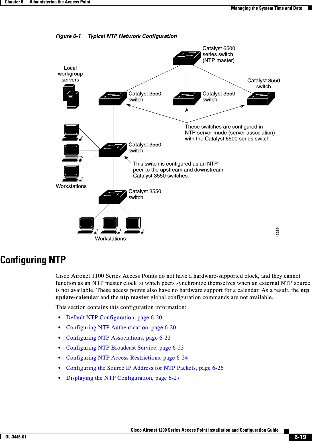
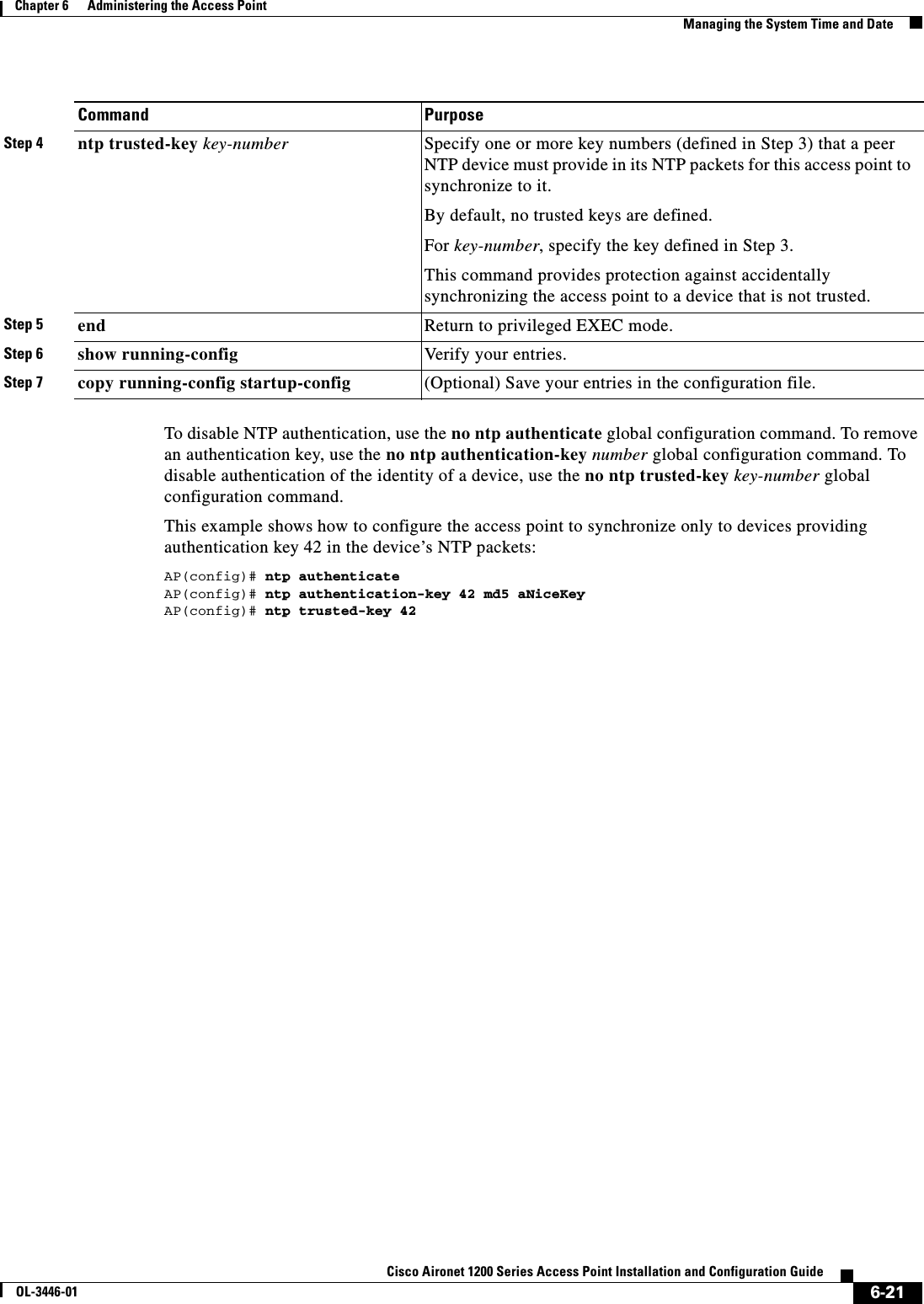
![6-22Cisco Aironet 1200 Series Access Point Installation and Configuration GuideOL-3446-01Chapter 6 Administering the Access PointManaging the System Time and DateConfiguring NTP AssociationsAn NTP association can be a peer association (this access point can either synchronize to the other device or allow the other device to synchronize to it), or it can be a server association (meaning that only this access point synchronizes to the other device, and not the other way around). Beginning in privileged EXEC mode, follow these steps to form an NTP association with another device:You need to configure only one end of an association; the other device can automatically establish the association. If you are using the default NTP version (version 3) and NTP synchronization does not occur, try using NTP version 2. Many NTP servers on the Internet run version 2.To remove a peer or server association, use the no ntp peer ip-address or the no ntp server ip-addressglobal configuration command.This example shows how to configure the access point to synchronize its system clock with the clock of the peer at IP address 172.16.22.44 using NTP version 2:AP(config)# ntp server 172.16.22.44 version 2Command PurposeStep 1 configure terminal Enter global configuration mode.Step 2 ntp peer ip-address [version number][key keyid] [source interface] [prefer]or ntp server ip-address [version number][key keyid] [source interface] [prefer]Configure the access point system clock to synchronize a peer or to be synchronized by a peer (peer association).orConfigure the access point system clock to be synchronized by a time server (server association).No peer or server associations are defined by default.•For ip-address in a peer association, specify either the IP address of the peer providing, or being provided, the clock synchronization. For a server association, specify the IP address of the time server providing the clock synchronization.•(Optional) For number, specify the NTP version number. The range is 1 to 3. By default, version 3 is selected.•(Optional) For keyid, enter the authentication key defined with the ntp authentication-key global configuration command.•(Optional) For interface, specify the interface from which to pick the IP source address. By default, the source IP address is taken from the outgoing interface.•(Optional) Enter the prefer keyword to make this peer or server the preferred one that provides synchronization. This keyword reduces switching back and forth between peers and servers.Step 3 end Return to privileged EXEC mode.Step 4 show running-config Verify your entries.Step 5 copy running-config startup-config (Optional) Save your entries in the configuration file.](https://usermanual.wiki/Cisco-Systems/102053.CRN-27004-Question-6-AP-user-manual/User-Guide-441628-Page-92.png)
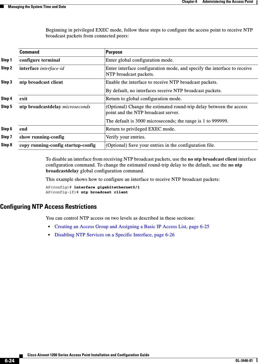
![6-23Cisco Aironet 1200 Series Access Point Installation and Configuration GuideOL-3446-01Chapter 6 Administering the Access PointManaging the System Time and DateConfiguring NTP Broadcast ServiceThe communications between devices running NTP (known as associations) are usually statically configured; each device is given the IP addresses of all devices with which it should form associations. Accurate timekeeping is possible by exchanging NTP messages between each pair of devices with an association. However, in a LAN environment, NTP can be configured to use IP broadcast messages instead. This alternative reduces configuration complexity because each device can simply be configured to send or receive broadcast messages. However, the information flow is one-way only.The access point can send or receive NTP broadcast packets on an interface-by-interface basis if there is an NTP broadcast server, such as a router, broadcasting time information on the network. The access point can send NTP broadcast packets to a peer so that the peer can synchronize to it. The access point can also receive NTP broadcast packets to synchronize its own clock. This section provides procedures for both sending and receiving NTP broadcast packets.Beginning in privileged EXEC mode, follow these steps to configure the access point to send NTP broadcast packets to peers so that they can synchronize their clock to the access point:To disable the interface from sending NTP broadcast packets, use the no ntp broadcast interface configuration command.This example shows how to configure an interface to send NTP version 2 packets:AP(config)# interface gigabitethernet0/1AP(config-if)# ntp broadcast version 2Command PurposeStep 1 configure terminal Enter global configuration mode.Step 2 interface interface-id Enter interface configuration mode, and specify the interface to send NTP broadcast packets.Step 3 ntp broadcast [version number] [key keyid][destination-address]Enable the interface to send NTP broadcast packets to a peer.By default, this feature is disabled on all interfaces.•(Optional) For number, specify the NTP version number. The range is 1 to 3. If you do not specify a version, version 3 is used.•(Optional) For keyid, specify the authentication key to use when sending packets to the peer.•(Optional) For destination-address, specify the IP address of the peer that is synchronizing its clock to this access point.Step 4 end Return to privileged EXEC mode.Step 5 show running-config Verify your entries.Step 6 copy running-config startup-config (Optional) Save your entries in the configuration file.Step 7 Configure the connected peers to receive NTP broadcast packets as described in the next procedure.](https://usermanual.wiki/Cisco-Systems/102053.CRN-27004-Question-6-AP-user-manual/User-Guide-441628-Page-93.png)
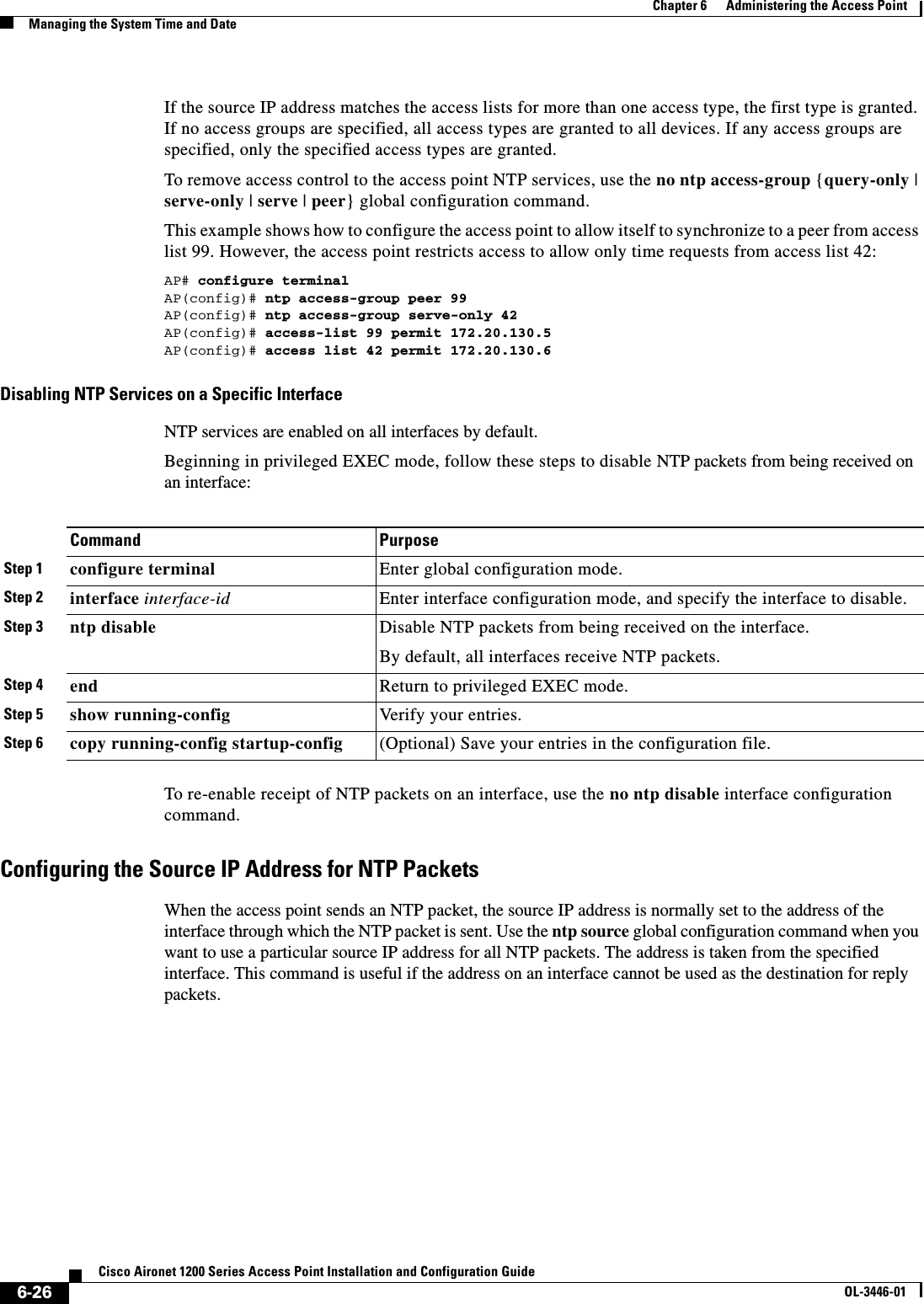
![6-25Cisco Aironet 1200 Series Access Point Installation and Configuration GuideOL-3446-01Chapter 6 Administering the Access PointManaging the System Time and DateCreating an Access Group and Assigning a Basic IP Access ListBeginning in privileged EXEC mode, follow these steps to control access to NTP services by using access lists:The access group keywords are scanned in this order, from least restrictive to most restrictive: 1. peer—Allows time requests and NTP control queries and allows the access point to synchronize itself to a device whose address passes the access list criteria.2. serve—Allows time requests and NTP control queries, but does not allow the access point to synchronize itself to a device whose address passes the access list criteria.3. serve-only—Allows only time requests from a device whose address passes the access list criteria.4. query-only—Allows only NTP control queries from a device whose address passes the access list criteria.Command PurposeStep 1 configure terminal Enter global configuration mode.Step 2 ntp access-group {query-only | serve-only | serve | peer}access-list-numberCreate an access group, and apply a basic IP access list.The keywords have these meanings:•query-only—Allows only NTP control queries.•serve-only—Allows only time requests.•serve—Allows time requests and NTP control queries, but does not allow the access point to synchronize to the remote device.•peer—Allows time requests and NTP control queries and allows the access point to synchronize to the remote device.For access-list-number, enter a standard IP access list number from 1 to 99. Step 3 access-list access-list-number permit source [source-wildcard]Create the access list.•For access-list-number, enter the number specified in Step 2.•Enter the permit keyword to permit access if the conditions are matched.•For source, enter the IP address of the device that is permitted access to the access point.•(Optional) For source-wildcard, enter the wildcard bits to be applied to the source.Note When creating an access list, remember that, by default, the end of the access list contains an implicit deny statement for everything if it did not find a match before reaching the end.Step 4 end Return to privileged EXEC mode.Step 5 show running-config Verify your entries.Step 6 copy running-config startup-config (Optional) Save your entries in the configuration file.](https://usermanual.wiki/Cisco-Systems/102053.CRN-27004-Question-6-AP-user-manual/User-Guide-441628-Page-95.png)
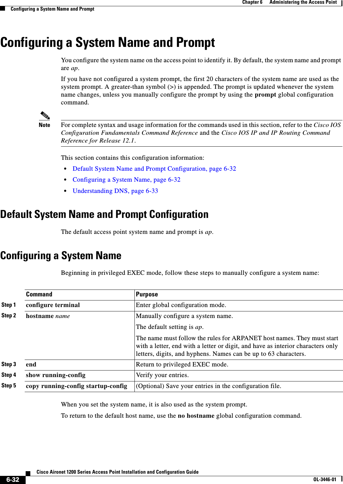
![6-27Cisco Aironet 1200 Series Access Point Installation and Configuration GuideOL-3446-01Chapter 6 Administering the Access PointManaging the System Time and DateBeginning in privileged EXEC mode, follow these steps to configure a specific interface from which the IP source address is to be taken:The specified interface is used for the source address for all packets sent to all destinations. If a source address is to be used for a specific association, use the source keyword in the ntp peer or ntp server global configuration command as described in the “Configuring NTP Associations” section on page 6-22.Displaying the NTP ConfigurationYou can use two privileged EXEC commands to display NTP information: •show ntp associations [detail]•show ntp statusFor detailed information about the fields in these displays, refer to the Cisco IOS Configuration Fundamentals Command Reference for Release 12.1.Configuring Time and Date ManuallyIf no other source of time is available, you can manually configure the time and date after the system is restarted. The time remains accurate until the next system restart. We recommend that you use manual configuration only as a last resort. If you have an outside source to which the access point can synchronize, you do not need to manually set the system clock. This section contains this configuration information:•Setting the System Clock, page 6-28•Displaying the Time and Date Configuration, page 6-28•Configuring the Time Zone, page 6-29•Configuring Summer Time (Daylight Saving Time), page 6-30Command PurposeStep 1 configure terminal Enter global configuration mode.Step 2 ntp source type number Specify the interface type and number from which the IP source address is taken.By default, the source address is determined by the outgoing interface.Step 3 end Return to privileged EXEC mode.Step 4 show running-config Verify your entries.Step 5 copy running-config startup-config (Optional) Save your entries in the configuration file.](https://usermanual.wiki/Cisco-Systems/102053.CRN-27004-Question-6-AP-user-manual/User-Guide-441628-Page-97.png)
![6-28Cisco Aironet 1200 Series Access Point Installation and Configuration GuideOL-3446-01Chapter 6 Administering the Access PointManaging the System Time and DateSetting the System ClockIf you have an outside source on the network that provides time services, such as an NTP server, you do not need to manually set the system clock.Beginning in privileged EXEC mode, follow these steps to set the system clock:This example shows how to manually set the system clock to 1:32 p.m. on July 23, 2001:AP# clock set 13:32:00 23 July 2001Displaying the Time and Date ConfigurationTo display the time and date configuration, use the show clock [detail] privileged EXEC command.The system clock keeps an authoritative flag that shows whether the time is authoritative (believed to be accurate). If the system clock has been set by a timing source such as NTP, the flag is set. If the time is not authoritative, it is used only for display purposes. Until the clock is authoritative and the authoritative flag is set, the flag prevents peers from synchronizing to the clock when the peers’ time is invalid.The symbol that precedes the show clock display has this meaning: •*—Time is not authoritative.•(blank)—Time is authoritative.•.—Time is authoritative, but NTP is not synchronized.Command PurposeStep 1 clock set hh:mm:ss day month yearor clock set hh:mm:ss month day yearManually set the system clock using one of these formats.•For hh:mm:ss, specify the time in hours (24-hour format), minutes, and seconds. The time specified is relative to the configured time zone.•For day, specify the day by date in the month.•For month, specify the month by name.•For year, specify the year (no abbreviation).Step 2 show running-config Verify your entries.Step 3 copy running-config startup-config (Optional) Save your entries in the configuration file.](https://usermanual.wiki/Cisco-Systems/102053.CRN-27004-Question-6-AP-user-manual/User-Guide-441628-Page-98.png)
![6-29Cisco Aironet 1200 Series Access Point Installation and Configuration GuideOL-3446-01Chapter 6 Administering the Access PointManaging the System Time and DateConfiguring the Time Zone Beginning in privileged EXEC mode, follow these steps to manually configure the time zone:The minutes-offset variable in the clock timezone global configuration command is available for those cases where a local time zone is a percentage of an hour different from UTC. For example, the time zone for some sections of Atlantic Canada (AST) is UTC-3.5, where the 3 means 3 hours and .5 means 50 percent. In this case, the necessary command is clock timezone AST -3 30.To set the time to UTC, use the no clock timezone global configuration command.Command PurposeStep 1 configure terminal Enter global configuration mode.Step 2 clock timezone zone hours-offset[minutes-offset]Set the time zone.The access point keeps internal time in universal time coordinated (UTC), so this command is used only for display purposes and when the time is manually set.•For zone, enter the name of the time zone to be displayed when standard time is in effect. The default is UTC.•For hours-offset, enter the hours offset from UTC.•(Optional) For minutes-offset, enter the minutes offset from UTC.Step 3 end Return to privileged EXEC mode.Step 4 show running-config Verify your entries.Step 5 copy running-config startup-config (Optional) Save your entries in the configuration file.](https://usermanual.wiki/Cisco-Systems/102053.CRN-27004-Question-6-AP-user-manual/User-Guide-441628-Page-99.png)
![6-30Cisco Aironet 1200 Series Access Point Installation and Configuration GuideOL-3446-01Chapter 6 Administering the Access PointManaging the System Time and DateConfiguring Summer Time (Daylight Saving Time)Beginning in privileged EXEC mode, follow these steps to configure summer time (daylight saving time) in areas where it starts and ends on a particular day of the week each year:The first part of the clock summer-time global configuration command specifies when summer time begins, and the second part specifies when it ends. All times are relative to the local time zone. The start time is relative to standard time. The end time is relative to summer time. If the starting month is after the ending month, the system assumes that you are in the southern hemisphere.This example shows how to specify that summer time starts on the first Sunday in April at 02:00 and ends on the last Sunday in October at 02:00:AP(config)# clock summer-time PDT recurring 1 Sunday April 2:00 last Sunday October 2:00 Command PurposeStep 1 configure terminal Enter global configuration mode.Step 2 clock summer-time zone recurring[week day month hh:mm week day month hh:mm [offset]]Configure summer time to start and end on the specified days every year. Summer time is disabled by default. If you specify clock summer-timezone recurring without parameters, the summer time rules default to the United States rules.•For zone, specify the name of the time zone (for example, PDT) to be displayed when summer time is in effect.•(Optional) For week, specify the week of the month (1 to 5 or last).•(Optional) For day, specify the day of the week (Sunday, Monday...).•(Optional) For month, specify the month (January, February...).•(Optional) For hh:mm, specify the time (24-hour format) in hours and minutes.•(Optional) For offset, specify the number of minutes to add during summer time. The default is 60.Step 3 end Return to privileged EXEC mode.Step 4 show running-config Verify your entries.Step 5 copy running-config startup-config (Optional) Save your entries in the configuration file.](https://usermanual.wiki/Cisco-Systems/102053.CRN-27004-Question-6-AP-user-manual/User-Guide-441628-Page-100.png)
![6-31Cisco Aironet 1200 Series Access Point Installation and Configuration GuideOL-3446-01Chapter 6 Administering the Access PointManaging the System Time and DateBeginning in privileged EXEC mode, follow these steps if summer time in your area does not follow a recurring pattern (configure the exact date and time of the next summer time events):The first part of the clock summer-time global configuration command specifies when summer time begins, and the second part specifies when it ends. All times are relative to the local time zone. The start time is relative to standard time. The end time is relative to summer time. If the starting month is after the ending month, the system assumes that you are in the southern hemisphere.To disable summer time, use the no clock summer-time global configuration command.This example shows how to set summer time to start on October 12, 2000, at 02:00, and end on April 26, 2001, at 02:00:AP(config)# clock summer-time pdt date 12 October 2000 2:00 26 April 2001 2:00Command PurposeStep 1 configure terminal Enter global configuration mode.Step 2 clock summer-time zone date [month date year hh:mm month date year hh:mm[offset]]orclock summer-time zone date [datemonth year hh:mm date month year hh:mm [offset]]Configure summer time to start on the first date and end on the second date.Summer time is disabled by default.•For zone, specify the name of the time zone (for example, PDT) to be displayed when summer time is in effect.•(Optional) For week, specify the week of the month (1 to 5 or last).•(Optional) For day, specify the day of the week (Sunday, Monday...).•(Optional) For month, specify the month (January, February...).•(Optional) For hh:mm, specify the time (24-hour format) in hours and minutes.•(Optional) For offset, specify the number of minutes to add during summer time. The default is 60.Step 3 end Return to privileged EXEC mode.Step 4 show running-config Verify your entries.Step 5 copy running-config startup-config (Optional) Save your entries in the configuration file.](https://usermanual.wiki/Cisco-Systems/102053.CRN-27004-Question-6-AP-user-manual/User-Guide-441628-Page-101.png)
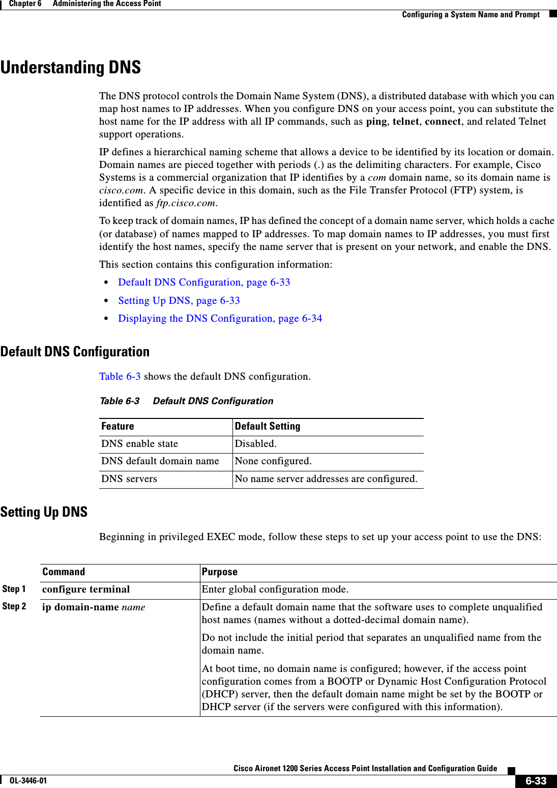
![6-34Cisco Aironet 1200 Series Access Point Installation and Configuration GuideOL-3446-01Chapter 6 Administering the Access PointCreating a BannerIf you use the access point IP address as its host name, the IP address is used and no DNS query occurs. If you configure a host name that contains no periods (.), a period followed by the default domain name is appended to the host name before the DNS query is made to map the name to an IP address. The default domain name is the value set by the ip domain-name global configuration command. If there is a period (.) in the host name, the IOS software looks up the IP address without appending any default domain name to the host name.To remove a domain name, use the no ip domain-name name global configuration command. To remove a name server address, use the no ip name-server server-address global configuration command. To disable DNS on the access point, use the no ip domain-lookup global configuration command.Displaying the DNS ConfigurationTo display the DNS configuration information, use the show running-config privileged EXEC command.Creating a BannerYou can configure a message-of-the-day (MOTD) and a login banner. The MOTD banner appears on all connected terminals at login and is useful for sending messages that affect all network users (such as impending system shutdowns).The login banner also appears on all connected terminals. It appears after the MOTD banner and before the login prompts. Note For complete syntax and usage information for the commands used in this section, refer to the Cisco IOS Configuration Fundamentals Command Reference for Release 12.2.Step 3 ip name-server server-address1[server-address2 ... server-address6]Specify the address of one or more name servers to use for name and address resolution.You can specify up to six name servers. Separate each server address with a space. The first server specified is the primary server. The access point sends DNS queries to the primary server first. If that query fails, the backup servers are queried.Step 4 ip domain-lookup (Optional) Enable DNS-based host name-to-address translation on your access point. This feature is enabled by default. If your network devices require connectivity with devices in networks for which you do not control name assignment, you can dynamically assign device names that uniquely identify your devices by using the global Internet naming scheme (DNS).Step 5 end Return to privileged EXEC mode.Step 6 show running-config Verify your entries.Step 7 copy running-config startup-config(Optional) Save your entries in the configuration file.Command Purpose](https://usermanual.wiki/Cisco-Systems/102053.CRN-27004-Question-6-AP-user-manual/User-Guide-441628-Page-104.png)
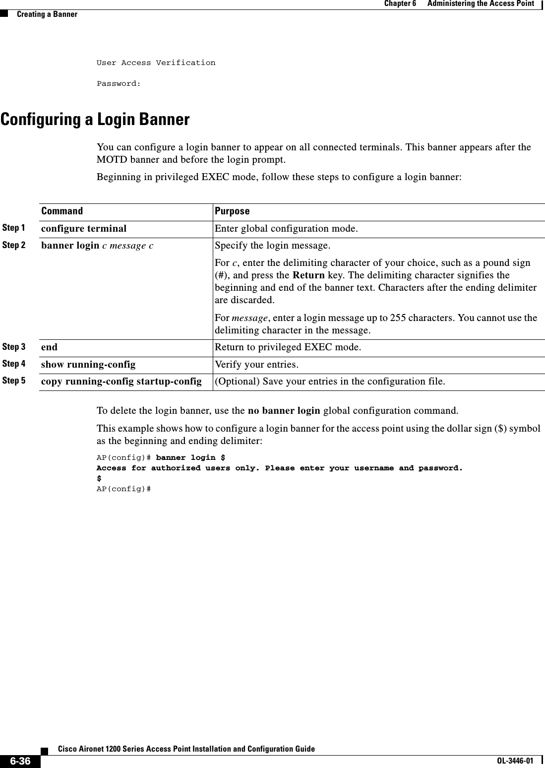
![6-35Cisco Aironet 1200 Series Access Point Installation and Configuration GuideOL-3446-01Chapter 6 Administering the Access PointCreating a BannerThis section contains this configuration information:•Default Banner Configuration, page 6-35•Configuring a Message-of-the-Day Login Banner, page 6-35•Configuring a Login Banner, page 6-36Default Banner ConfigurationThe MOTD and login banners are not configured.Configuring a Message-of-the-Day Login BannerYou can create a single or multiline message banner that appears on the screen when someone logs into the access point. Beginning in privileged EXEC mode, follow these steps to configure a MOTD login banner:To delete the MOTD banner, use the no banner motd global configuration command.This example shows how to configure a MOTD banner for the access point using the pound sign (#) symbol as the beginning and ending delimiter:AP(config)# banner motd #This is a secure site. Only authorized users are allowed.For access, contact technical support.#AP(config)#This example shows the banner displayed from the previous configuration:Unix> telnet 172.2.5.4Trying 172.2.5.4...Connected to 172.2.5.4.Escape character is '^]'.This is a secure site. Only authorized users are allowed.For access, contact technical support.Command PurposeStep 1 configure terminal Enter global configuration mode.Step 2 banner motd c message c Specify the message of the day.For c, enter the delimiting character of your choice, such as a pound sign (#), and press the Return key. The delimiting character signifies the beginning and end of the banner text. Characters after the ending delimiter are discarded.For message, enter a banner message up to 255 characters. You cannot use the delimiting character in the message.Step 3 end Return to privileged EXEC mode.Step 4 show running-config Verify your entries.Step 5 copy running-config startup-config (Optional) Save your entries in the configuration file.](https://usermanual.wiki/Cisco-Systems/102053.CRN-27004-Question-6-AP-user-manual/User-Guide-441628-Page-105.png)
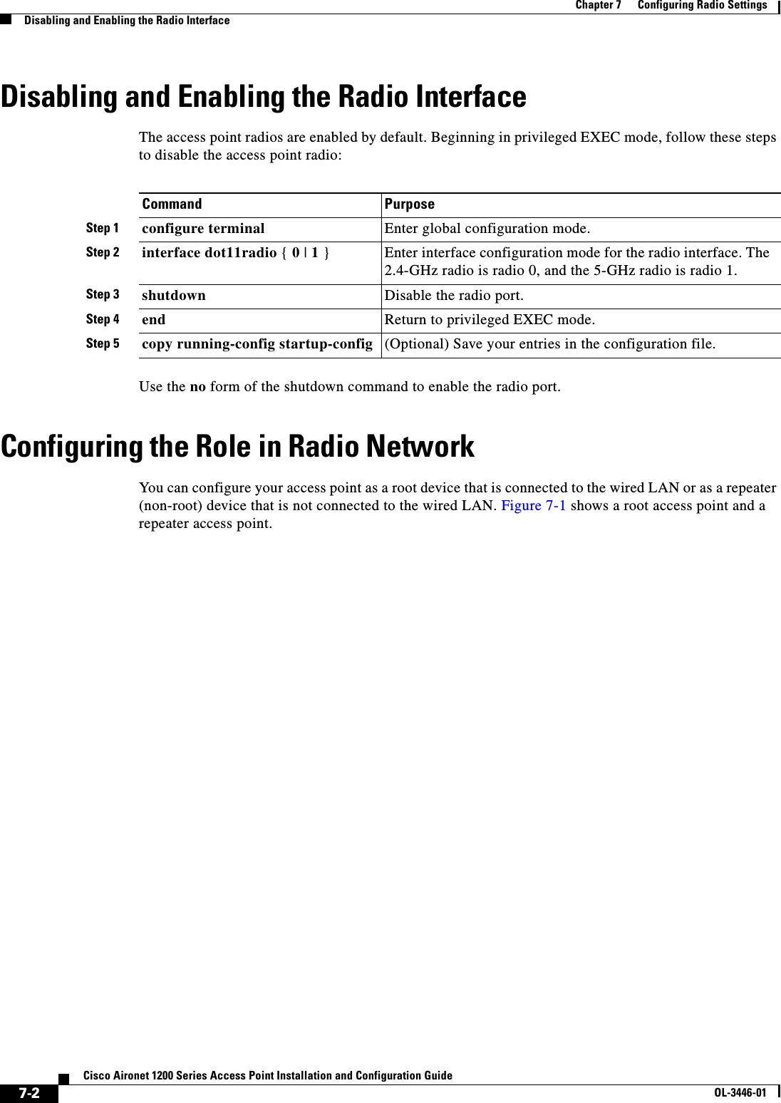
![7-4Cisco Aironet 1200 Series Access Point Installation and Configuration GuideOL-3446-01Chapter 7 Configuring Radio SettingsConfiguring Radio Data RatesConfiguring Radio Data RatesYou use the data rate settings to choose the data rates the access point uses for data transmission. The rates are expressed in megabits per second. The access point always attempts to transmit at the highest data rate set to Basic, also called Require on the browser-based interface. If there are obstacles or interference, the access point steps down to the highest rate that allows data transmission. You can set each data rate (1, 2, 5.5, and 11 megabits per second) to one of three states: •Basic (this is the default state for all data rates)—Allows transmission at this rate for all packets, both unicast and multicast. At least one of the access point's data rates must be set to Basic. •Enabled—The access point transmits only unicast packets at this rate; multicast packets are sent at one of the data rates set to Basic. •Disabled—The access point does not transmit data at this rate. Note At least one data rate must be set to basic.You can use the Data Rate settings to set up an access point to serve client devices operating at specific data rates. For example, to set up the 2.4-GHz radio for 11 megabits per second (Mbps) service only, set the 11-Mbps rate to Basic and set the other data rates to Enabled. To set up the access point to serve only client devices operating at 1 and 2 Mbps, set 1 and 2 to Basic and set the rest of the data rates to Enabled. To set up the 5-GHz radio for 54 Mbps service only, set the 54-Mbps rate to Basic and set the other data rates to Enabled.You can also configure the access point to set the data rates automatically to optimize either range or throughput. When you enter range for the data rate setting, the access point sets the 1 Mbps rate to basic and the other rates to enabled. When you enter throughput for the data rate setting, the access point sets all four data rates to basic.Beginning in privileged EXEC mode, follow these steps to configure the radio data rates:Step 3 station rolerepeater |root [fallback { shutdown | repeater } ]Set the access point role.•Set the role to repeater or root.•(Optional) Select the radio’s fallback role. If the access point’s Ethernet port is disabled or disconnected from the wired LAN, the access point can either shut down its radio port or become a repeater access point associated to a nearby root access point.Step 4 end Return to privileged EXEC mode.Step 5 copy running-config startup-config (Optional) Save your entries in the configuration file.Command PurposeCommand PurposeStep 1 configure terminal Enter global configuration mode.Step 2 interface dot11radio { 0 | 1 } Enter interface configuration mode for the radio interface. The 2.4-GHz radio is radio 0, and the 5-GHz radio is radio 1.](https://usermanual.wiki/Cisco-Systems/102053.CRN-27004-Question-6-AP-user-manual/User-Guide-441628-Page-110.png)
![7-5Cisco Aironet 1200 Series Access Point Installation and Configuration GuideOL-3446-01Chapter 7 Configuring Radio SettingsConfiguring Radio Transmit PowerUse the no form of the speed command to disable data rates. When you use the no form of the command, all data rates are disabled except the rates you name in the command. This example shows how to disable data rate 1.0:ap1200# configure terminalap1200(config)# interface dot11radio 0ap1200(config-if)# no speed basic-2.0 basic-5.5 basic-11.0ap1200(config-if)# endData rate 1 is disabled, and the rest of the rates are set to basic.This example shows how to set up the access point for 11-Mbps service only:ap1200# configure terminalap1200(config)# interface dot11radio 0ap1200(config-if)# no speed basic-11.0ap1200(config-if)# endData rate 11 is set to basic, and the rest of the data rates are set to disabled.Configuring Radio Transmit PowerBeginning in privileged EXEC mode, follow these steps to set the transmit power on your access point radio:Step 3 speedThese options are available for the 2.4-GHz radio:{[1.0] [11.0] [2.0] [5.5] [basic-1.0][basic-11.0] [basic-2.0] [basic-5.5] | range | throughput}These options are available for the 5-GHz radio:{[6.0] [9.0] [12.0] [18.0] [24.0][36.0] [48.0] [54.0] [basic-6.0][basic-9.0] [basic-12.0] [basic-18.0][basic-24.0] [basic-36.0][basic-48.0] [basic-54.0] |range | throughput}Set each data rate to basic or enabled, or enter range to optimize access point range or throughput to optimize throughput.•(Optional) Enter 1.0,2.0,5.5, and 11.0 to set these data rates to enabled on the 2.4-GHz radio. Enter 6.0,9.0,12.0,18.0,24.0,36.0,48.0, and 54.0 to set these data rates to enabled on the 5-GHz radio.•(Optional) Enter basic-1.0,basic-2.0, basic-5.5,andbasic-11.0 to set these data rates to basic on the 2.4-GHz radio. Enter basic-6.0,basic-9.0,basic-12.0,basic-18.0,basic-24.0,basic-36.0,basic-48.0, and basic-54.0 to set these data rates to basic on the 5-GHz radio.•(Optional) Enter range or throughput to automatically optimize radio range or throughput. When you enter range, The access point sets the lowest data rate to basic and the other rates to enabled. When you enter throughput, the access point sets all data rates to basic.Step 4 end Return to privileged EXEC mode.Step 5 copy running-config startup-config (Optional) Save your entries in the configuration file.Command PurposeCommand PurposeStep 1 configure terminal Enter global configuration mode.Step 2 interface dot11radio { 0 | 1 } Enter interface configuration mode for the radio interface. The 2.4-GHz radio is radio 0, and the 5-GHz radio is radio 1.](https://usermanual.wiki/Cisco-Systems/102053.CRN-27004-Question-6-AP-user-manual/User-Guide-441628-Page-111.png)
![8-4Cisco Aironet 1200 Series Access Point Installation and Configuration GuideOL-3446-01Chapter 8 Configuring Multiple SSIDsConfiguring Multiple SSIDsNote You use the ssid command’s authentication options to configure an authentication type for each SSID. See Chapter 10, “Configuring Authentication Types,” for instructions on configuring authentication types.Use the no form of the command to disable the SSID or to disable SSID features.This example shows how to:•Name an SSID•Configure the SSID for RADIUS accounting•Set the maximum number of client devices that can associate using this SSID to 15•Assign the SSID to a VLANap1200# configure terminalap1200(config)# configure interface dot11radio 0ap1200(config-if)# ssid batmanap1200(config-ssid)# accounting accounting-method-listap1200(config-ssid)# max-associations 15ap1200(config-ssid)# vlan 3762ap1200(config-ssid)# endUsing a RADIUS Server to Restrict SSIDsTo prevent client devices from associating to the access point using an unauthorized SSID, you can create a list of authorized SSIDs that clients must use on your RADIUS authentication server. The SSID authorization process consists of these steps:1. A client device associates to the access point using any SSID configured on the access point. 2. The client begins RADIUS authentication.3. The RADIUS server returns a list of SSIDs that the client is allowed to use. The access point checks the list for a match of the SSID used by the client. There are three possible outcomes:a. If the SSID that the client used to associate to the access point matches an entry in the allowed list returned by the RADIUS server, the client is allowed network access after completing all authentication requirements. b. If the access point does not find a match for the client in the allowed list of SSIDs, the access point disassociates the client. Step 8 infrastructure-ssid [optional] (Optional) Designate the SSID as the SSID that other access points and workgroup bridges use to associate to this access point. If you do not designate an SSID as the infrastructure SSID, infrastructure devices can associate to the access point using any SSID. If you designate an SSID as the infrastructure SSID, infrastructure devices must associate to the access point using that SSID unless you also enter the optional keyword.Step 9 end Return to privileged EXEC mode.Step 10 copy running-config startup-config (Optional) Save your entries in the configuration file.Command Purpose](https://usermanual.wiki/Cisco-Systems/102053.CRN-27004-Question-6-AP-user-manual/User-Guide-441628-Page-126.png)

![9-3Cisco Aironet 1200 Series Access Point Installation and Configuration GuideOL-3446-01Chapter 9 Configuring WEP and WEP FeaturesConfiguring WEP and WEP FeaturesCreating WEP KeysBeginning in privileged EXEC mode, follow these steps to create a WEP key and set the key properties:This example shows how to create a 128-bit WEP key in slot 1 for VLAN 22 and sets the key as the transmit key:ap1200# configure terminalap1200(config)# configure interface dot11radio 0ap1200(config-if)# encryption vlan 22 key 1 size 128 12345678901234567890123456 transmit-keyap1200(config-ssid)# endEnabling and Disabling WEP and Enabling TKIP and MICBeginning in privileged EXEC mode, follow these steps to enable WEP, TKIP, and MIC:Command PurposeStep 1 configure terminal Enter global configuration mode.Step 2 interface dot11radio { 0 | 1 } Enter interface configuration mode for the radio interface. The 2.4-GHz radio is radio 0, and the 5-GHz radio is radio 1.Step 3 encryption[vlan vlan-id]key 1-4size {40 | 128 } encryption-key[transmit-key]Create a WEP key and set up its properties.•(Optional) Select the VLAN for which you want to create a key.•Name the key slot in which this WEP key resides. You can assign up to 4 WEP keys for each VLAN.•Enter the key and set the size of the key, either 40-bit or 128-bit. 40-bit keys contain 10 hexadecimal digits; 128-bit keys contain 26 hexadecimal digits. •(Optional) Set this key as the transmit key. The key in slot 1 is the transmit key by default, but you can set any key as the transmit key.Step 4 end Return to privileged EXEC mode.Step 5 copy running-config startup-config (Optional) Save your entries in the configuration file.Command PurposeStep 1 configure terminal Enter global configuration mode.Step 2 interface dot11radio { 0 | 1 } Enter interface configuration mode for the radio interface. The 2.4-GHz radio is radio 0, and the 5-GHz radio is radio 1.](https://usermanual.wiki/Cisco-Systems/102053.CRN-27004-Question-6-AP-user-manual/User-Guide-441628-Page-131.png)
![9-4Cisco Aironet 1200 Series Access Point Installation and Configuration GuideOL-3446-01Chapter 9 Configuring WEP and WEP FeaturesConfiguring WEP and WEP FeaturesUse the no form of the encryption command to disable WEP or to disable WEP features.This example sets WEP to mandatory for VLAN 22 and enables MIC and TKIP.ap1200# configure terminalap1200(config)# configure interface dot11radio 0ap1200(config-if)# encryption vlan 22 mode wep mandatory mic key-hashap1200(config-ssid)# endEnabling and Disabling Broadcast Key RotationBroadcast key rotation is disabled by default. Beginning in privileged EXEC mode, follow these steps to enable broadcast key rotation:Use the no form of the encryption command to disable broadcast key rotation.This example enables broadcast key rotation on VLAN 22 and sets the rotation interval to 300 seconds:ap1200# configure terminalap1200(config)# configure interface dot11radio 0ap1200(config-if)# broadcast-key vlan 22 change 300ap1200(config-ssid)# endStep 3 encryption[vlan vlan-id]mode wep {optional [key-hash] | mandatory [mic] [key-hash]}Enable WEP, MIC, and TKIP.•(Optional) Select the VLAN for which you want to enable WEP and WEP features.•Set the WEP level and enable TKIP and MIC. If you enter optional, client devices can associate to the access point with or without WEP enabled. You can enable TKIP with WEP set to optional but you cannot enable MIC. If you enter mandatory, client devices must have WEP enabled to associate to the access point. You can enable both TKIP and MIC with WEP set to mandatory.Step 4 end Return to privileged EXEC mode.Step 5 copy running-config startup-config (Optional) Save your entries in the configuration file.Command PurposeCommand PurposeStep 1 configure terminal Enter global configuration mode.Step 2 interface dot11radio { 0 | 1 } Enter interface configuration mode for the radio interface. The 2.4-GHz radio is radio 0, and the 5-GHz radio is radio 1.Step 3 broadcast-keychange seconds[vlan vlan-id]Enable broadcast key rotation.•Enter the number of seconds between each rotation of the broadcast key. •(Optional) Enter a VLAN for which you want to enable broadcast key rotation.Step 4 end Return to privileged EXEC mode.Step 5 copy running-config startup-config (Optional) Save your entries in the configuration file.](https://usermanual.wiki/Cisco-Systems/102053.CRN-27004-Question-6-AP-user-manual/User-Guide-441628-Page-132.png)
![10-7Cisco Aironet 1200 Series Access Point Installation and Configuration GuideOL-3446-01Chapter 10 Configuring Authentication TypesConfiguring Authentication TypesStep 4 authentication open [mac-address list-name [alternate]][eap list-name](Optional) Set the authentication type to open for this SSID. Open authentication allows any device to authenticate and then attempt to communicate with the access point. •(Optional) Set the SSID’s authentication type to open with MAC address authentication. The access point forces all client devices to perform MAC-address authentication before they are allowed to join the network. For list-name,specify the authentication method list. Click this link for more information on method lists: http://www.cisco.com/univercd/cc/td/doc/product/software/ios122/122cgcr/fsecur_c/fsaaa/scfathen.htm#xtocid2Use the alternate keyword to allow client devices to join the network using either MAC or EAP authentication; clients that successfully complete either authentication are allowed to join the network.•(Optional) Set the SSID’s authentication type to open with EAP authentication. The access point forces all client devices to perform EAP authentication before they are allowed to join the network. For list-name, specify the authentication method list. Note An access point configured for EAP authentication forces all client devices that associate to perform EAP authentication. Client devices that do not use EAP cannot use the access point.Step 5 authentication shared[mac-address list-name][eap list-name](Optional) Set the authentication type for the SSID to shared key.Note Because of shared key's security flaws, Cisco recommends that you avoid using it.Note You can assign shared key athentication to only one SSID.•(Optional) Set the SSID’s authentication type to shared key with MAC address authentication. For list-name, specify the authentication method list. •(Optional) Set the SSID’s authentication type to shared key with EAP authentication. For list-name, specify the authentication method list.Command Purpose](https://usermanual.wiki/Cisco-Systems/102053.CRN-27004-Question-6-AP-user-manual/User-Guide-441628-Page-139.png)
 Set the authentication type for the SSID to Network-EAP. Using the Extensible Authentication Protocol (EAP) to interact with an EAP-compatible RADIUS server, the access point helps a wireless client device and the RADIUS server to perform mutual authentication and derive a dynamic unicast WEP key. However, the access point does not force all client devices to perform EAP authentication. •(Optional) Set the SSID’s authentication type to Network-EAP with MAC address authentication. All client devices that associate to the access point are required to perform MAC-address authentication. For list-name, specify the authentication method list. Step 7 end Return to privileged EXEC mode.Step 8 copy running-config startup-config (Optional) Save your entries in the configuration file.Command PurposeCommand PurposeStep 1 configure terminal Enter global configuration mode.Step 2 dot11 holdoff-time seconds Enter the number of seconds a client device must wait before it can reattempt to authenticate following a failed authentication. Enter a value from 1 to 65555 seconds.Step 3 interface dot11radio { 0 | 1 } Enter interface configuration mode for the radio interface. The 2.4-GHz radio is radio 0, and the 5-GHz radio is radio 1.Step 4 dot1x client-timeout seconds Enter the number of seconds the access point should wait for a reply from a client attempting to authenticate before the authentication fails. Enter a value from 1 to 65555 seconds.](https://usermanual.wiki/Cisco-Systems/102053.CRN-27004-Question-6-AP-user-manual/User-Guide-441628-Page-140.png)
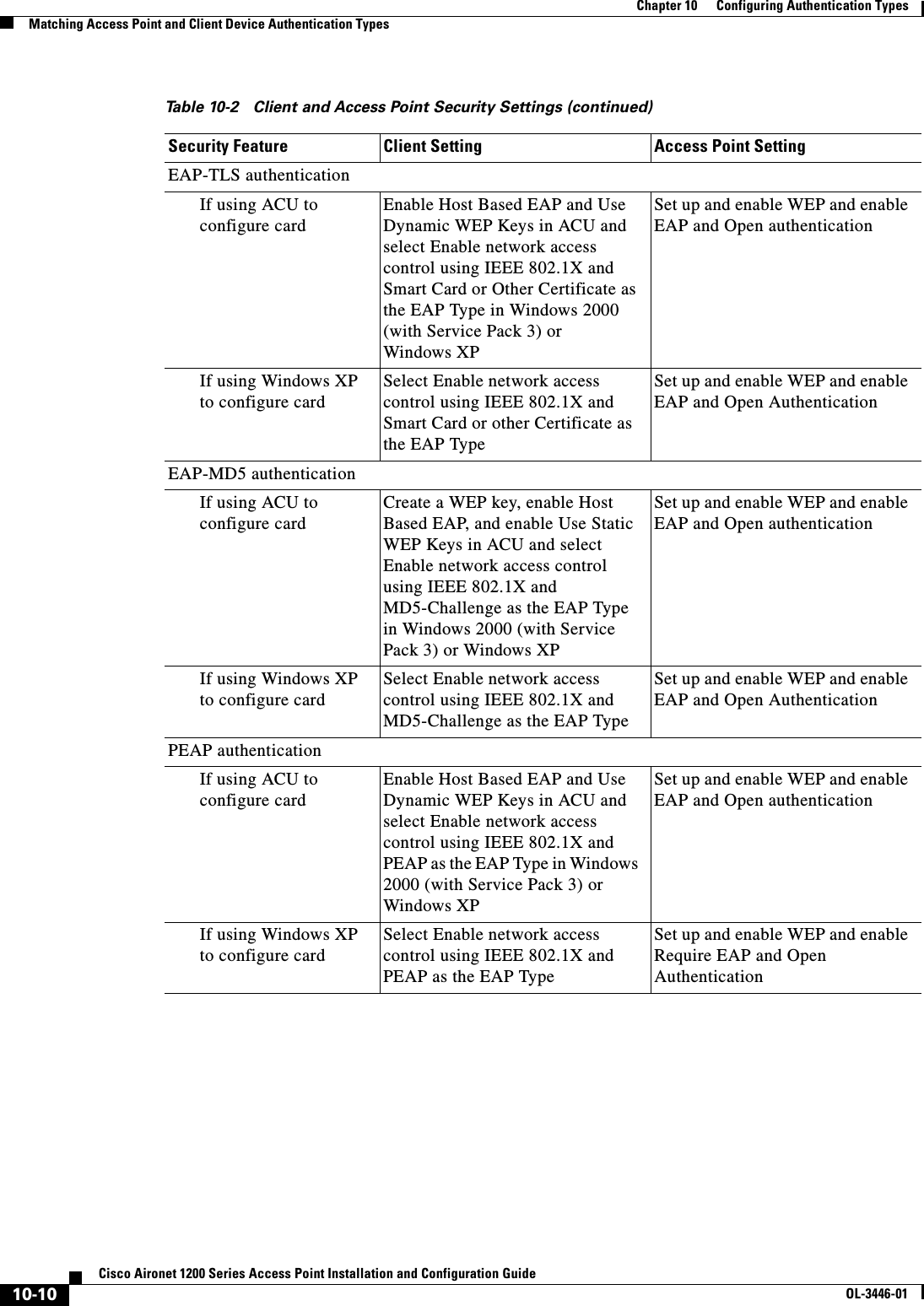
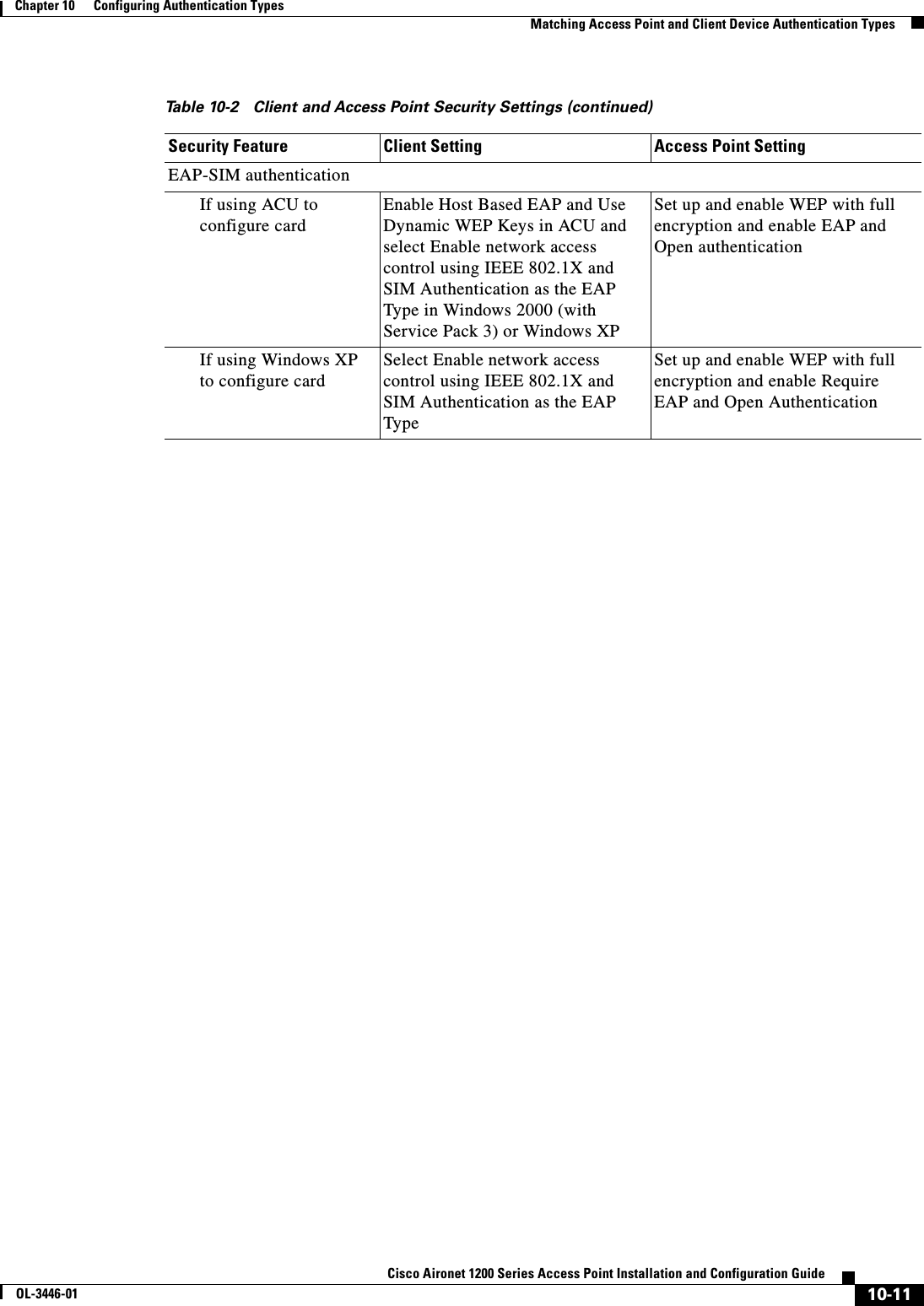
![10-9Cisco Aironet 1200 Series Access Point Installation and Configuration GuideOL-3446-01Chapter 10 Configuring Authentication TypesMatching Access Point and Client Device Authentication TypesUse the no form of these commands to reset the values to default settings. Matching Access Point and Client Device Authentication Types To use the authentication types described in this section, the access point authentication settings must match the authentication settings on the client adapters that associate to the access point. Refer to the Cisco Aironet Wireless LAN Client Adapters Installation and Configuration Guide for Windows for instructions on setting authentication types on wireless client adapters. Refer to Chapter 9, “Configuring WEP and WEP Features,” for instructions on configuring WEP on the access point. Table 10-2 lists the client and access point settings required for each authentication type.Step 5 dot1x reauth-period seconds [server]Enter the interval in seconds that the access point waits before forcing an authenticated client to reauthenticate.•(Optional) Enter the server keyword to configure the access point to use the rauthentication period specified by the authentication server. If you use this option, configure your authentication server with RADIUS attribute 27, Session-Timeout. This attribute sets the maximum number of seconds of service to be provided to the client before termination of the session or prompt. The server sends this attribute to the access point when a client device performs EAP authentication.Step 6 end Return to privileged EXEC mode.Step 7 copy running-config startup-config (Optional) Save your entries in the configuration file.Command PurposeTable 10-2 Client and Access Point Security SettingsSecurity Feature Client Setting Access Point SettingStatic WEP with open authenticationCreate a WEP key and enable Use Static WEP Keys and Open AuthenticationSet up and enable WEP and enable Open AuthenticationStatic WEP with shared key authenticationCreate a WEP key and enable Use Static WEP Keys and Shared Key AuthenticationSet up and enable WEP and enable Shared Key AuthenticationLEAP authentication Enable LEAP Set up and enable WEP and enable Network-EAP](https://usermanual.wiki/Cisco-Systems/102053.CRN-27004-Question-6-AP-user-manual/User-Guide-441628-Page-141.png)

![11-6Cisco Aironet 1200 Series Access Point Installation and Configuration GuideOL-3446-01Chapter 11 Configuring RADIUS and TACACS+ ServersConfiguring and Enabling RADIUSTo remove the specified RADIUS server, use the no radius-server host hostname | ip-address global configuration command. This example shows how to configure one RADIUS server to be used for authentication and another to be used for accounting:AP(config)# radius-server host 172.29.36.49 auth-port 1612 key rad1AP(config)# radius-server host 172.20.36.50 acct-port 1618 key rad2Step 3 radius-server host {hostname | ip-address} [auth-port port-number][acct-port port-number] [timeoutseconds] [retransmit retries] [keystring]Specify the IP address or host name of the remote RADIUS server host.•(Optional) For auth-port port-number, specify the UDP destination port for authentication requests.•(Optional) For acct-port port-number, specify the UDP destination port for accounting requests.•(Optional) For timeout seconds, specify the time interval that the access point waits for the RADIUS server to reply before retransmitting. The range is 1 to 1000. This setting overrides the radius-server timeout global configuration command setting. If no timeout is set with the radius-server host command, the setting of the radius-server timeout command is used.•(Optional) For retransmit retries, specify the number of times a RADIUS request is resent to a server if that server is not responding or responding slowly. The range is 1 to 1000. If no retransmit value is set with the radius-server host command, the setting of the radius-server retransmit global configuration command is used.•(Optional) For key string, specify the authentication and encryption key used between the access point and the RADIUS daemon running on the RADIUS server. Note The key is a text string that must match the encryption key used on the RADIUS server. Always configure the key as the last item in the radius-server host command. Leading spaces are ignored, but spaces within and at the end of the key are used. If you use spaces in your key, do not enclose the key in quotation marks unless the quotation marks are part of the key.To configure the access point to recognize more than one host entry associated with a single IP address, enter this command as many times as necessary, making sure that each UDP port number is different. The access point software searches for hosts in the order in which you specify them. Set the timeout, retransmit, and encryption key values to use with the specific RADIUS host.Step 4 end Return to privileged EXEC mode.Step 5 show running-config Verify your entries.Step 6 copy running-config startup-config (Optional) Save your entries in the configuration file.Command Purpose](https://usermanual.wiki/Cisco-Systems/102053.CRN-27004-Question-6-AP-user-manual/User-Guide-441628-Page-150.png)
![11-8Cisco Aironet 1200 Series Access Point Installation and Configuration GuideOL-3446-01Chapter 11 Configuring RADIUS and TACACS+ ServersConfiguring and Enabling RADIUSTo disable AAA, use the no aaa new-model global configuration command. To disable AAA authentication, use the no aaa authentication login {default | list-name}method1 [method2...] global configuration command. To either disable RADIUS authentication for logins or to return to the default value, use the no login authentication {default | list-name} line configuration command.Step 3 aaa authentication login {default | list-name}method1 [method2...]Create a login authentication method list.•To create a default list that is used when a named list is not specified in the login authentication command, use the default keyword followed by the methods that are to be used in default situations. The default method list is automatically applied to all interfaces. For more information on list names, click this link: http://www.cisco.com/univercd/cc/td/doc/product/software/ios122/122cgcr/fsecur_c/fsaaa/scfathen.htm#xtocid2•For method1..., specify the actual method the authentication algorithm tries. The additional methods of authentication are used only if the previous method returns an error, not if it fails.Select one of these methods:•line—Use the line password for authentication. You must define a line password before you can use this authentication method. Use the password password line configuration command.•local—Use the local username database for authentication. You must enter username information in the database. Use the usernamepassword global configuration command.•radius—Use RADIUS authentication. You must configure the RADIUS server before you can use this authentication method. For more information, see the “Identifying the RADIUS Server Host”section on page 11-4.Step 4 line [console | tty | vty]line-number[ending-line-number]Enter line configuration mode, and configure the lines to which you want to apply the authentication list.Step 5 login authentication {default | list-name}Apply the authentication list to a line or set of lines.•If you specify default, use the default list created with the aaa authentication login command.•For list-name, specify the list created with the aaa authentication login command.Step 6 radius-server attribute 32 include-in-access-req format %hConfigure the access point to send its system name in the NAS_ID attribute for authentication.Step 7 end Return to privileged EXEC mode.Step 8 show running-config Verify your entries.Step 9 copy running-config startup-config (Optional) Save your entries in the configuration file.Command Purpose](https://usermanual.wiki/Cisco-Systems/102053.CRN-27004-Question-6-AP-user-manual/User-Guide-441628-Page-152.png)
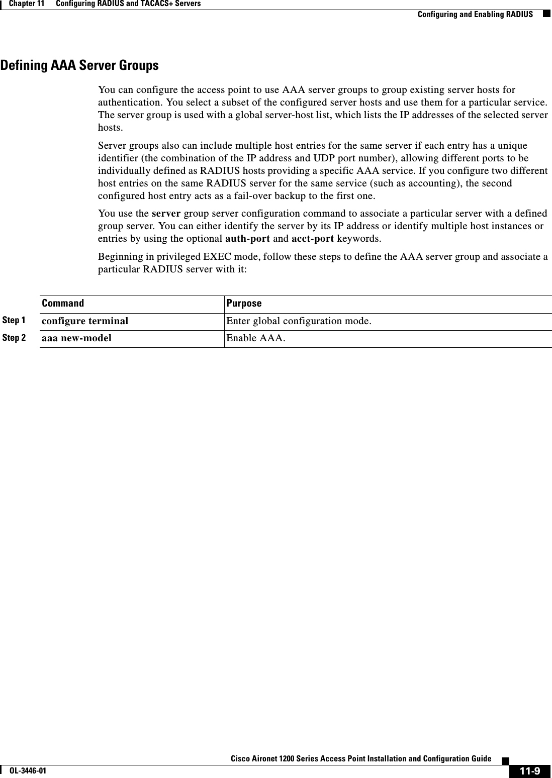
![11-10Cisco Aironet 1200 Series Access Point Installation and Configuration GuideOL-3446-01Chapter 11 Configuring RADIUS and TACACS+ ServersConfiguring and Enabling RADIUSStep 3 radius-server host {hostname | ip-address} [auth-port port-number][acct-port port-number] [timeoutseconds] [retransmit retries] [keystring]Specify the IP address or host name of the remote RADIUS server host.•(Optional) For auth-port port-number, specify the UDP destination port for authentication requests.•(Optional) For acct-port port-number, specify the UDP destination port for accounting requests.•(Optional) For timeout seconds, specify the time interval that the access point waits for the RADIUS server to reply before retransmitting. The range is 1 to 1000. This setting overrides the radius-server timeout global configuration command setting. If no timeout is set with the radius-server host command, the setting of the radius-server timeout command is used.•(Optional) For retransmit retries, specify the number of times a RADIUS request is resent to a server if that server is not responding or responding slowly. The range is 1 to 1000. If no retransmit value is set with the radius-server host command, the setting of the radius-server retransmit global configuration command is used.•(Optional) For key string, specify the authentication and encryption key used between the access point and the RADIUS daemon running on the RADIUS server. Note The key is a text string that must match the encryption key used on the RADIUS server. Always configure the key as the last item in the radius-server host command. Leading spaces are ignored, but spaces within and at the end of the key are used. If you use spaces in your key, do not enclose the key in quotation marks unless the quotation marks are part of the key.To configure the access point to recognize more than one host entry associated with a single IP address, enter this command as many times as necessary, making sure that each UDP port number is different. The access point software searches for hosts in the order in which you specify them. Set the timeout, retransmit, and encryption key values to use with the specific RADIUS host.Step 4 aaa group server radius group-name Define the AAA server-group with a group name.This command puts the access point in a server group configuration mode.Step 5 server ip-address Associate a particular RADIUS server with the defined server group. Repeat this step for each RADIUS server in the AAA server group.Each server in the group must be previously defined in Step 2.Step 6 end Return to privileged EXEC mode.Step 7 show running-config Verify your entries.Step 8 copy running-config startup-config (Optional) Save your entries in the configuration file.Step 9 Enable RADIUS login authentication. See the “Configuring RADIUS Login Authentication” section on page 11-7.Command Purpose](https://usermanual.wiki/Cisco-Systems/102053.CRN-27004-Question-6-AP-user-manual/User-Guide-441628-Page-154.png)
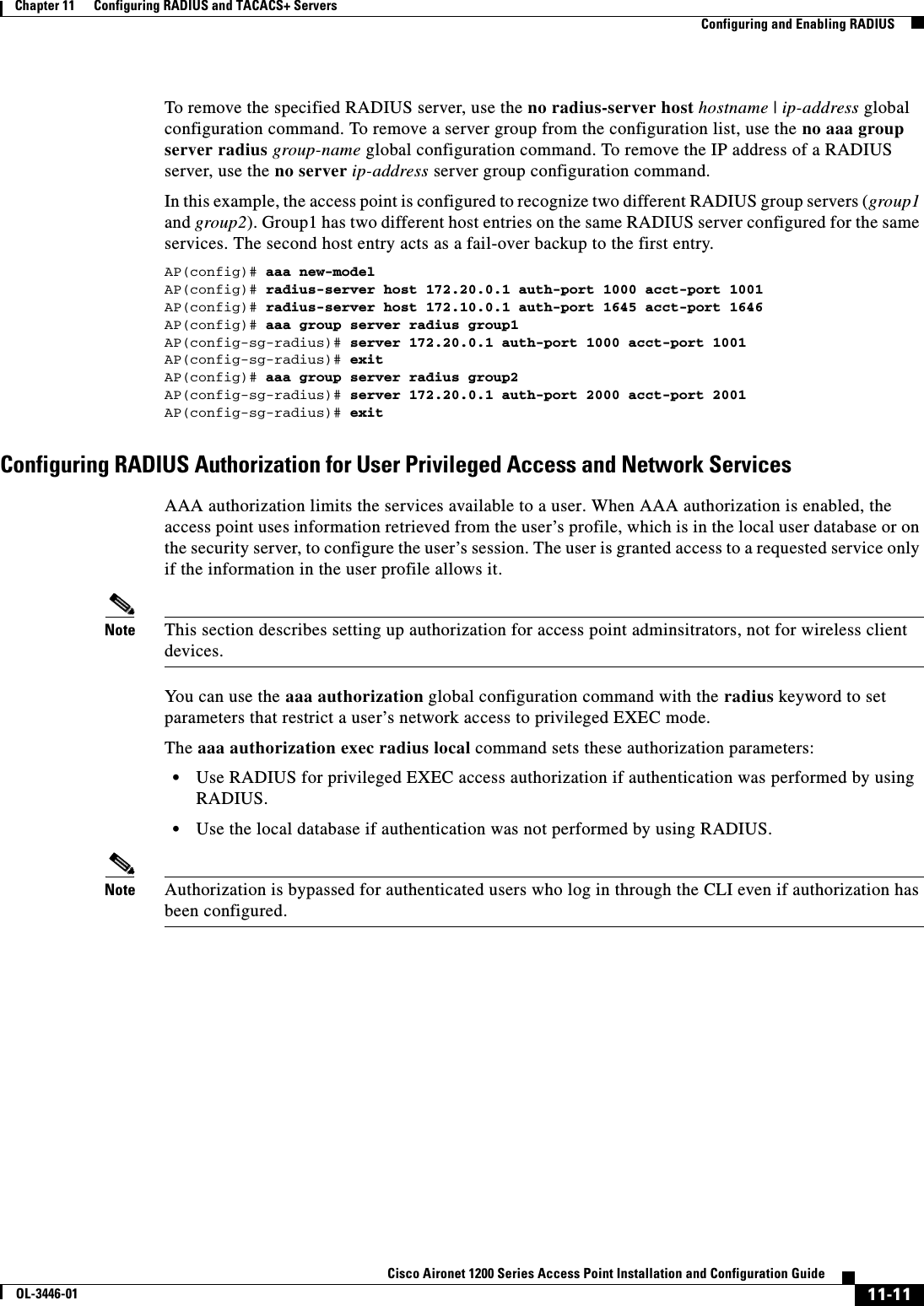
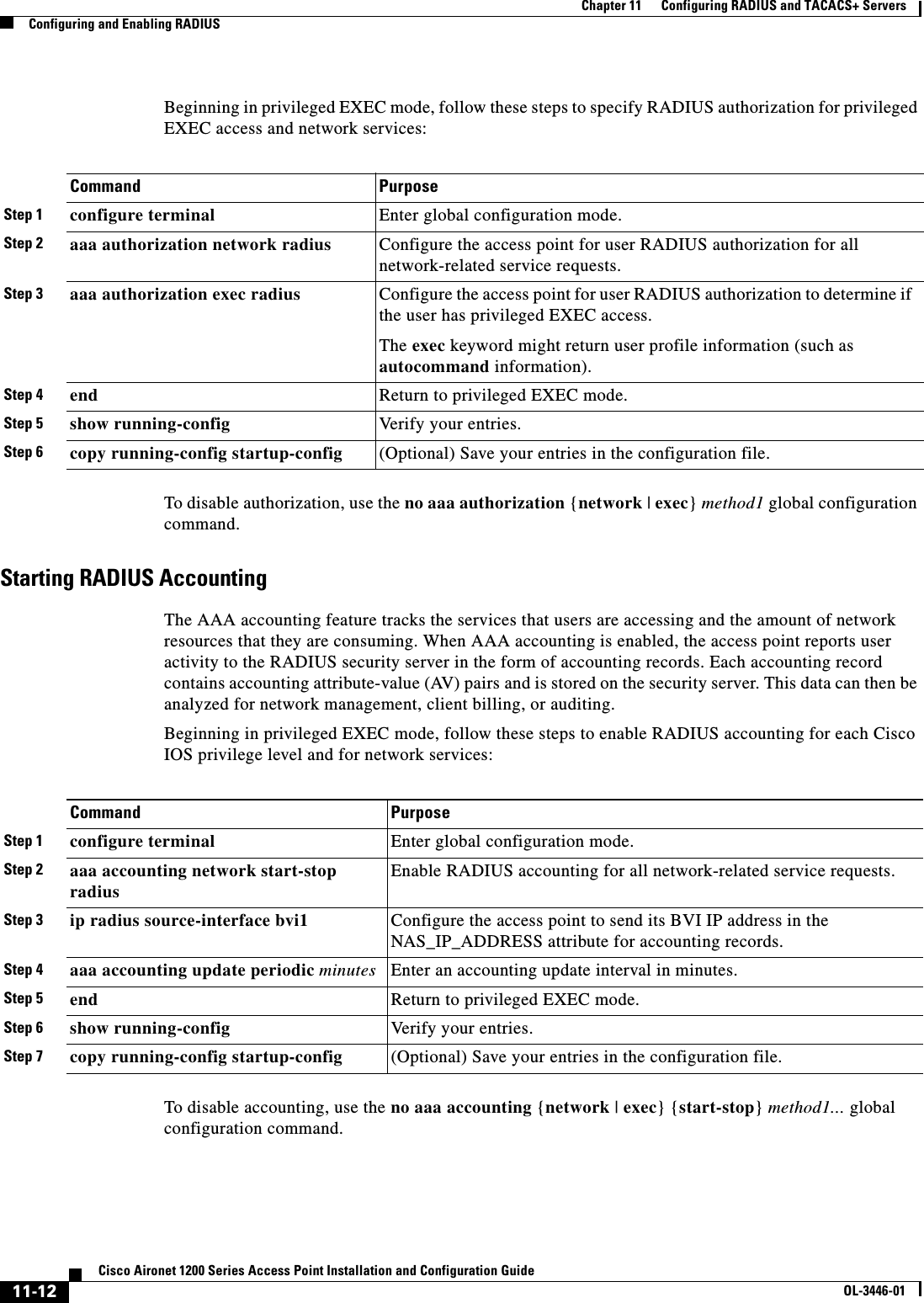
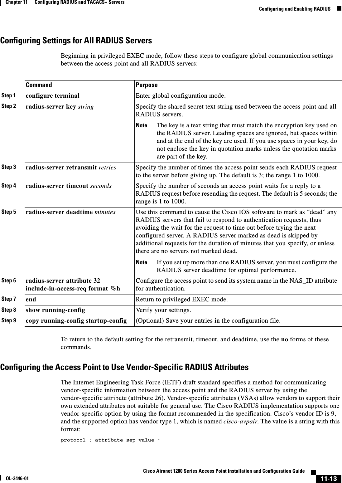
![11-14Cisco Aironet 1200 Series Access Point Installation and Configuration GuideOL-3446-01Chapter 11 Configuring RADIUS and TACACS+ ServersConfiguring and Enabling RADIUSProtocol is a value of the Cisco protocol attribute for a particular type of authorization. Attribute and value are an appropriate AV pair defined in the Cisco TACACS+ specification, and sep is = for mandatory attributes and the asterisk (*) for optional attributes. This allows the full set of features available for TACACS+ authorization to also be used for RADIUS. For example, the following AV pair activates Cisco’s multiple named ip address pools feature during IP authorization (during PPP’s IPCP address assignment):cisco-avpair= ”ip:addr-pool=first“The following example shows how to provide a user logging in from an access point with immediate access to privileged EXEC commands:cisco-avpair= ”shell:priv-lvl=15“ Other vendors have their own unique vendor IDs, options, and associated VSAs. For more information about vendor IDs and VSAs, refer to RFC 2138, “Remote Authentication Dial-In User Service (RADIUS).”Beginning in privileged EXEC mode, follow these steps to configure the access point to recognize and use VSAs:For a complete list of RADIUS attributes or more information about VSA 26, refer to the “RADIUS Attributes” appendix in the Cisco IOS Security Configuration Guide for Release 12.2.Configuring the Access Point for Vendor-Proprietary RADIUS Server CommunicationAlthough an IETF draft standard for RADIUS specifies a method for communicating vendor-proprietary information between the access point and the RADIUS server, some vendors have extended the RADIUS attribute set in a unique way. Cisco IOS software supports a subset of vendor-proprietary RADIUS attributes.As mentioned earlier, to configure RADIUS (whether vendor-proprietary or IETF draft-compliant), you must specify the host running the RADIUS server daemon and the secret text string it shares with the access point. You specify the RADIUS host and secret text string by using the radius-server global configuration commands.Command PurposeStep 1 configure terminal Enter global configuration mode.Step 2 radius-server vsa send [accounting | authentication]Enable the access point to recognize and use VSAs as defined by RADIUS IETF attribute 26.•(Optional) Use the accounting keyword to limit the set of recognized vendor-specific attributes to only accounting attributes.•(Optional) Use the authentication keyword to limit the set of recognized vendor-specific attributes to only authentication attributes.If you enter this command without keywords, both accounting and authentication vendor-specific attributes are used.Step 3 end Return to privileged EXEC mode.Step 4 show running-config Verify your settings.Step 5 copy running-config startup-config (Optional) Save your entries in the configuration file.](https://usermanual.wiki/Cisco-Systems/102053.CRN-27004-Question-6-AP-user-manual/User-Guide-441628-Page-158.png)
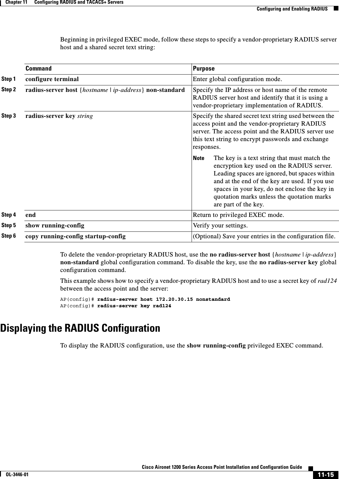
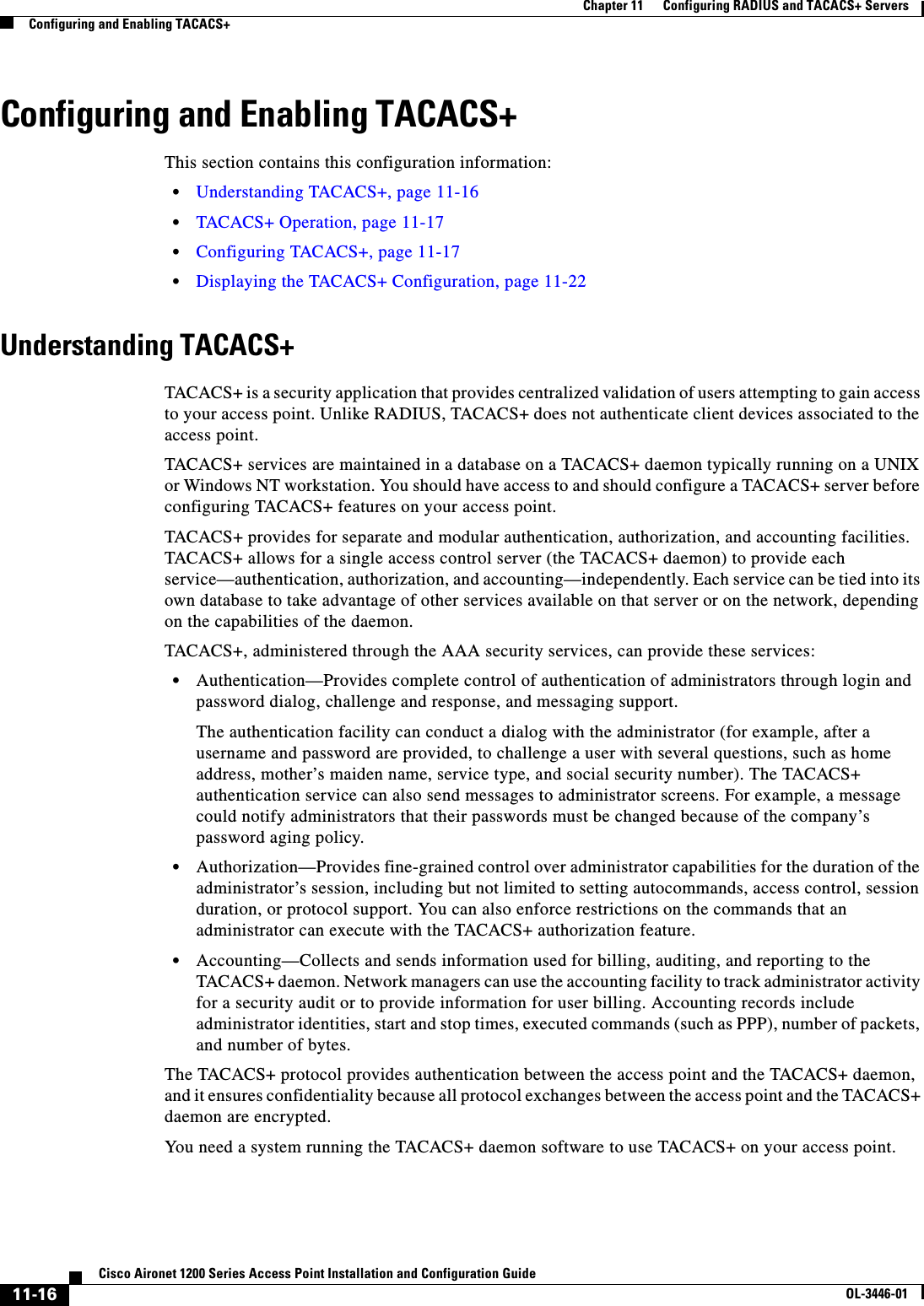
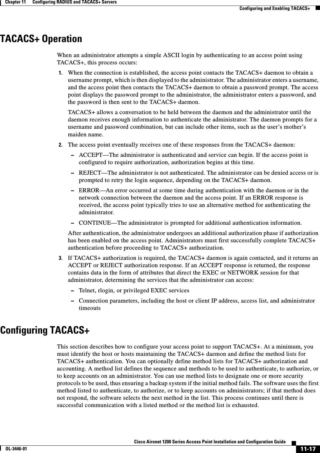
![11-18Cisco Aironet 1200 Series Access Point Installation and Configuration GuideOL-3446-01Chapter 11 Configuring RADIUS and TACACS+ ServersConfiguring and Enabling TACACS+This section contains this configuration information:•Default TACACS+ Configuration, page 11-18•Identifying the TACACS+ Server Host and Setting the Authentication Key, page 11-18•Configuring TACACS+ Login Authentication, page 11-19•Configuring TACACS+ Authorization for Privileged EXEC Access and Network Services, page 11-20•Starting TACACS+ Accounting, page 11-21Default TACACS+ ConfigurationTACACS+ and AAA are disabled by default.To prevent a lapse in security, you cannot configure TACACS+ through a network management application. When enabled, TACACS+ can authenticate administrators accessing the access point through the CLI.Identifying the TACACS+ Server Host and Setting the Authentication KeyYou can configure the access point to use a single server or AAA server groups to group existing server hosts for authentication. You can group servers to select a subset of the configured server hosts and use them for a particular service. The server group is used with a global server-host list and contains the list of IP addresses of the selected server hosts.Beginning in privileged EXEC mode, follow these steps to identify the IP host or host maintaining TACACS+ server and optionally set the encryption key:Command PurposeStep 1 configure terminal Enter global configuration mode.Step 2 tacacs-server host hostname [port integer] [timeout integer] [key string]Identify the IP host or hosts maintaining a TACACS+ server. Enter this command multiple times to create a list of preferred hosts. The software searches for hosts in the order in which you specify them.•For hostname, specify the name or IP address of the host.•(Optional) For port integer, specify a server port number. The default is port 49. The range is 1 to 65535.•(Optional) For timeout integer, specify a time in seconds the access point waits for a response from the daemon before it times out and declares an error. The default is 5 seconds. The range is 1 to 1000 seconds.•(Optional) For key string, specify the encryption key for encrypting and decrypting all traffic between the access point and the TACACS+ daemon. You must configure the same key on the TACACS+ daemon for encryption to be successful.Step 3 aaa new-model Enable AAA.Step 4 aaa group server tacacs+ group-name (Optional) Define the AAA server-group with a group name.This command puts the access point in a server group subconfiguration mode.](https://usermanual.wiki/Cisco-Systems/102053.CRN-27004-Question-6-AP-user-manual/User-Guide-441628-Page-162.png)
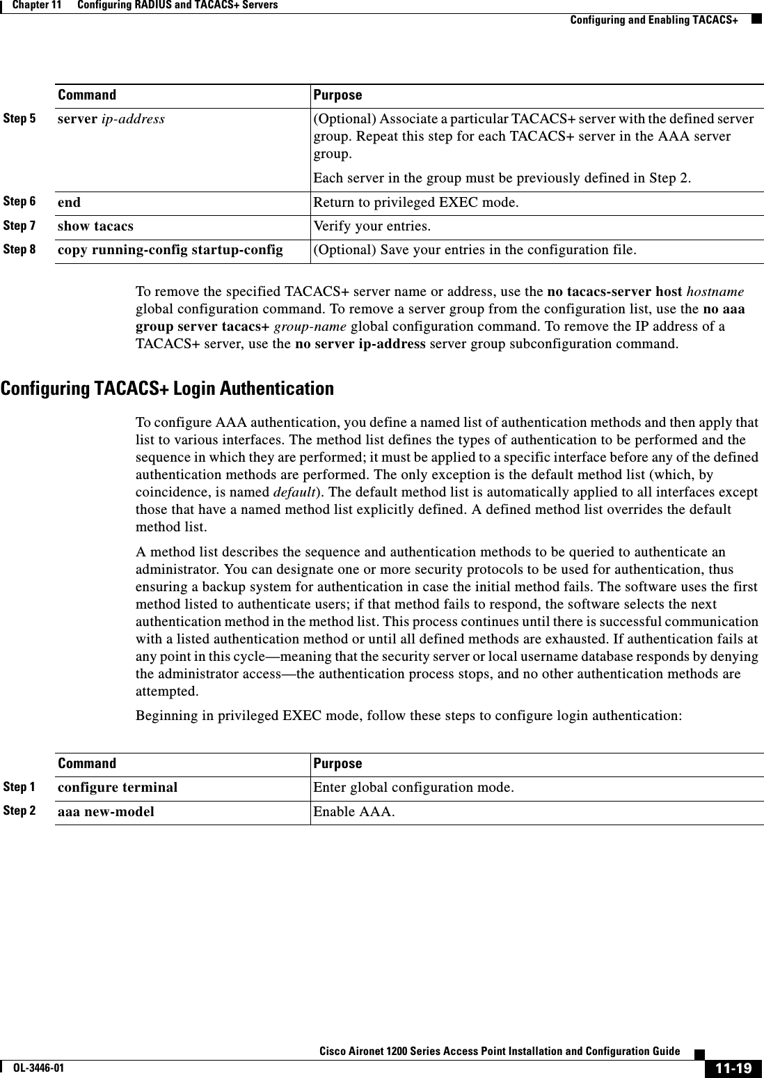
![11-20Cisco Aironet 1200 Series Access Point Installation and Configuration GuideOL-3446-01Chapter 11 Configuring RADIUS and TACACS+ ServersConfiguring and Enabling TACACS+To disable AAA, use the no aaa new-model global configuration command. To disable AAA authentication, use the no aaa authentication login {default | list-name}method1 [method2...] global configuration command. To either disable TACACS+ authentication for logins or to return to the default value, use the no login authentication {default | list-name} line configuration command.Configuring TACACS+ Authorization for Privileged EXEC Access and Network ServicesAAA authorization limits the services available to an administrator. When AAA authorization is enabled, the access point uses information retrieved from the administrator’s profile, which is located either in the local user database or on the security server, to configure the administrator’s session. The administrator is granted access to a requested service only if the information in the administrator profile allows it.You can use the aaa authorization global configuration command with the tacacs+ keyword to set parameters that restrict an administrator’s network access to privileged EXEC mode. Step 3 aaa authentication login {default | list-name}method1 [method2...]Create a login authentication method list.•To create a default list that is used when a named list is not specified in the login authentication command, use the default keyword followed by the methods that are to be used in default situations. The default method list is automatically applied to all interfaces.•For list-name, specify a character string to name the list you are creating. •For method1..., specify the actual method the authentication algorithm tries. The additional methods of authentication are used only if the previous method returns an error, not if it fails.Select one of these methods:•line—Use the line password for authentication. You must define a line password before you can use this authentication method. Use the password password line configuration command.•local—Use the local username database for authentication. You must enter username information into the database. Use the usernamepassword global configuration command.•tacacs+—Uses TACACS+ authentication. You must configure the TACACS+ server before you can use this authentication method.Step 4 line [console | tty | vty]line-number[ending-line-number]Enter line configuration mode, and configure the lines to which you want to apply the authentication list.Step 5 login authentication {default | list-name}Apply the authentication list to a line or set of lines.•If you specify default, use the default list created with the aaa authentication login command.•For list-name, specify the list created with the aaa authentication login command.Step 6 end Return to privileged EXEC mode.Step 7 show running-config Verify your entries.Step 8 copy running-config startup-config (Optional) Save your entries in the configuration file.Command Purpose](https://usermanual.wiki/Cisco-Systems/102053.CRN-27004-Question-6-AP-user-manual/User-Guide-441628-Page-164.png)
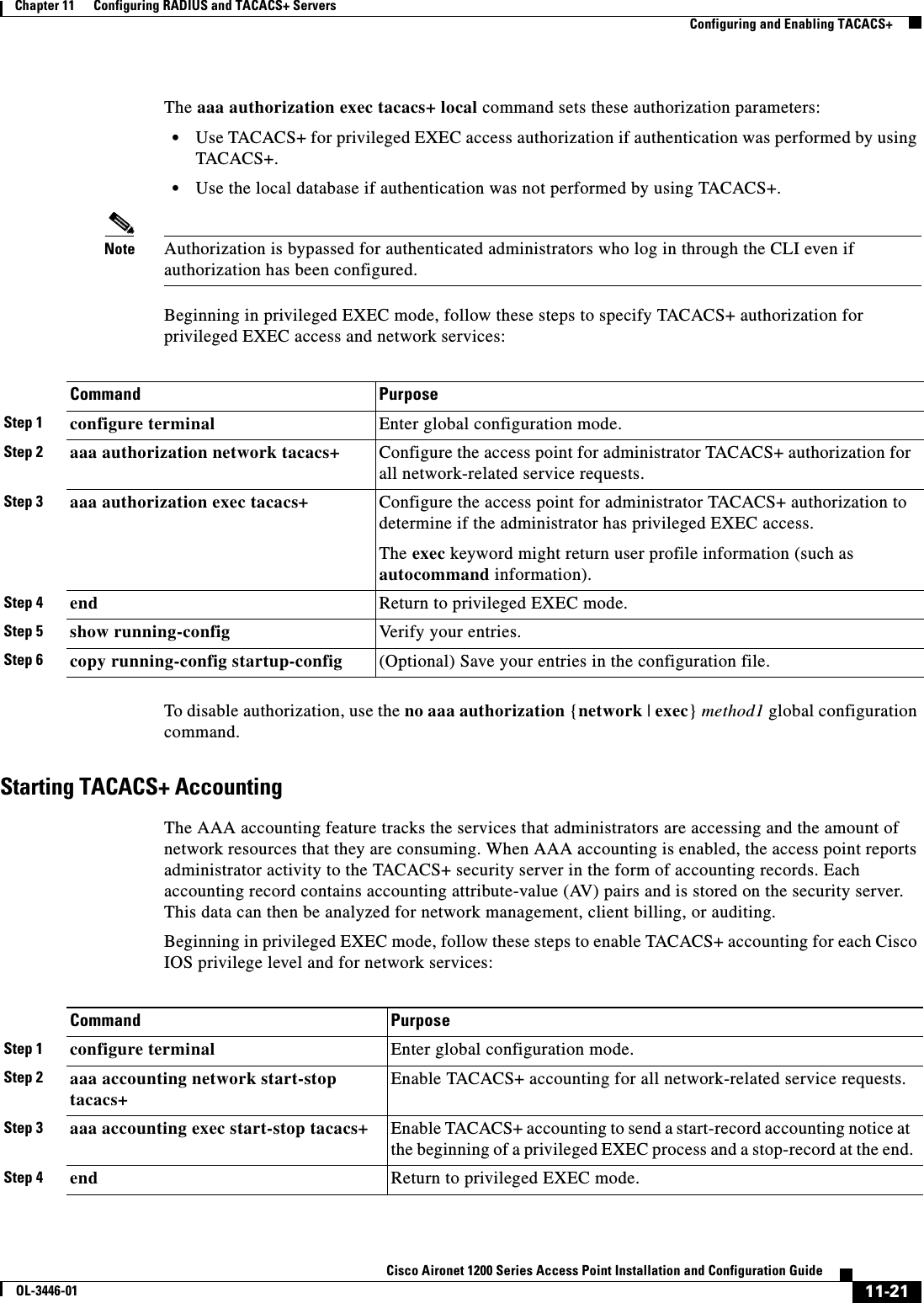
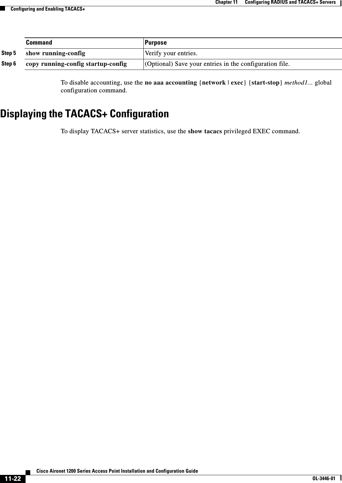
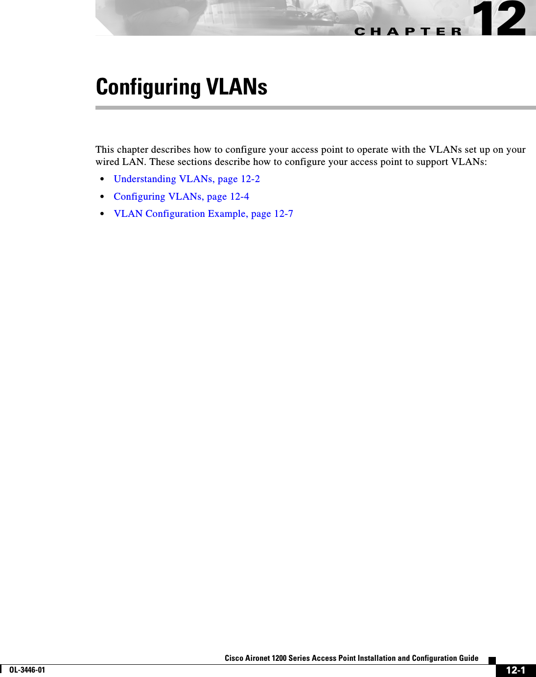
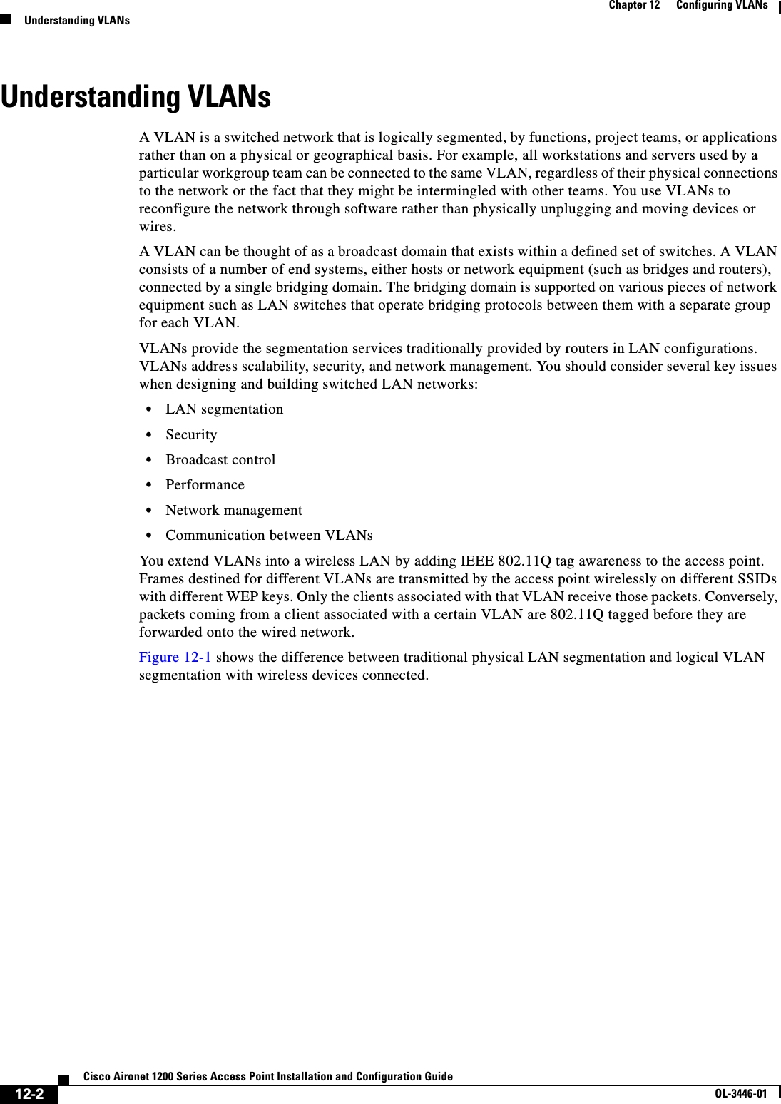
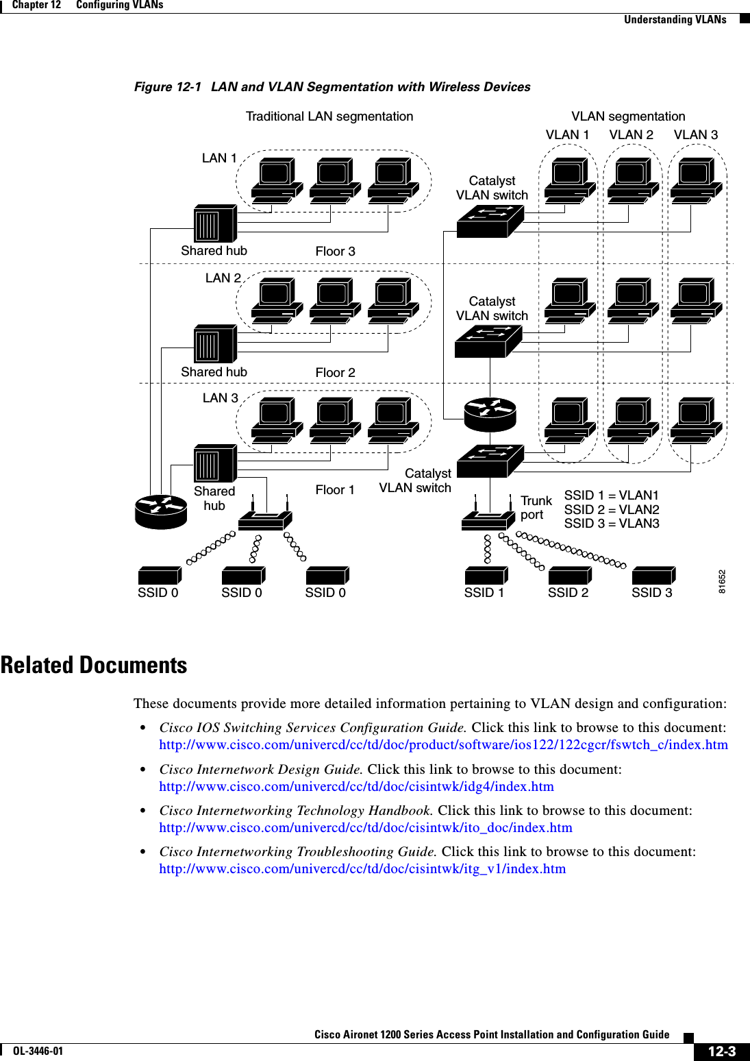
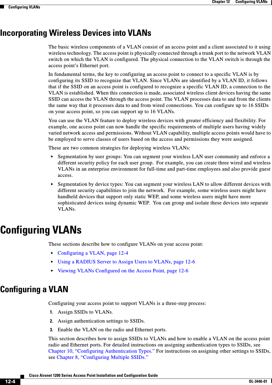
![12-5Cisco Aironet 1200 Series Access Point Installation and Configuration GuideOL-3446-01Chapter 12 Configuring VLANsConfiguring VLANsYou can configure up to 16 SSIDs on the access point, so you can support up to 16 VLANs that are configured on your LAN. Beginning in privileged EXEC mode, follow these steps to assign an SSID to a VLAN and enable the VLAN on the access point radio and Ethernet ports:This example shows how to:•Name an SSID•Assign the SSID to a VLAN•Enable the VLAN on the radio and Ethernet ports as the native VLANap1200# configure terminalap1200(config)# interface dot11radio0ap1200(config-if)# ssid batmanap1200(config-ssid)# vlan 1ap1200(config-ssid)# exitap1200(config)# interface dot11radio0.1ap1200(config-subif)# encapsulation dot1q 1 nativeap1200(config-subif)# exitCommand PurposeStep 1 configure terminal Enter global configuration mode.Step 2 interface dot11radio0 Enter interface configuration mode for the radio interface.Step 3 ssid ssid-string Create an SSID and enter SSID configuration mode for the new SSID. The SSID can consist of up to 32 alphanumeric characters. SSIDs are case sensitive.Note You use the ssid command’s authentication options to configure an authentication type for each SSID. See Chapter 10, “Configuring Authentication Types,” for instructions on configuring authentication types.Step 4 vlan vlan-id (Optional) Assign the SSID to a VLAN on your network. Client devices that associate using the SSID are grouped into this VLAN. Enter a VLAN ID from 1 to 4095.Step 5 exit Return to interface configuration mode for the radio interface.Step 6 interface dot11radio0.x Enter interface configuration mode for the radio VLAN sub interface.Step 7 encapsulation dot1q vlan-id[native]Enable a VLAN on the radio interface. (Optional) Designate the VLAN as the native VLAN. On many networks, the native VLAN is VLAN 1.Step 8 exit Return to global configuration mode.Step 9 interface fastEthernet0.x Enter interface configuration mode for the Ethernet VLAN subinterface.Step 10 encapsulation dot1q vlan-id[native]Enable a VLAN on the Ethernet interface. (Optional) Designate the VLAN as the native VLAN. On many networks, the native VLAN is VLAN 1.Step 11 end Return to privileged EXEC mode.Step 12 copy running-config startup-config (Optional) Save your entries in the configuration file.](https://usermanual.wiki/Cisco-Systems/102053.CRN-27004-Question-6-AP-user-manual/User-Guide-441628-Page-171.png)
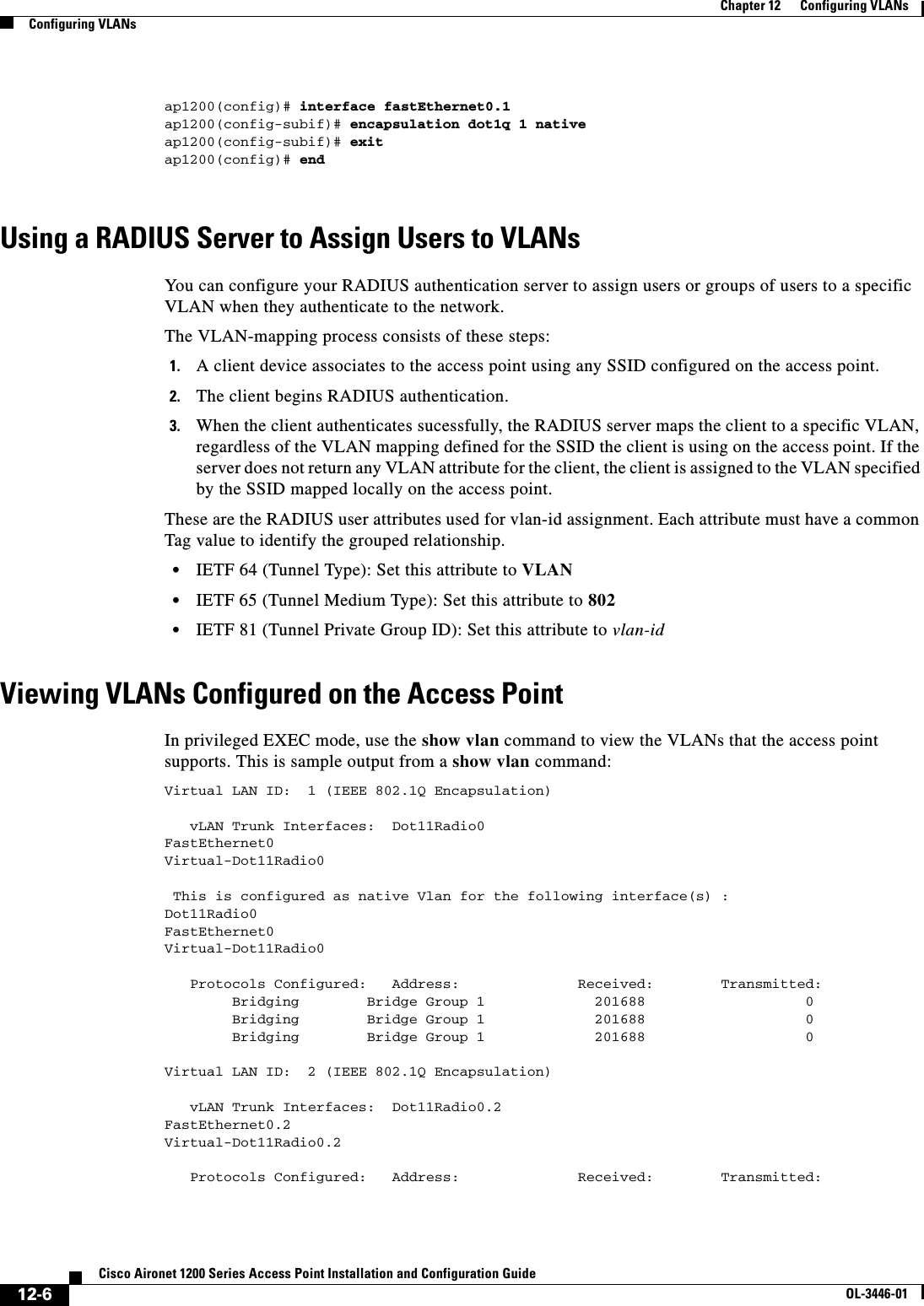
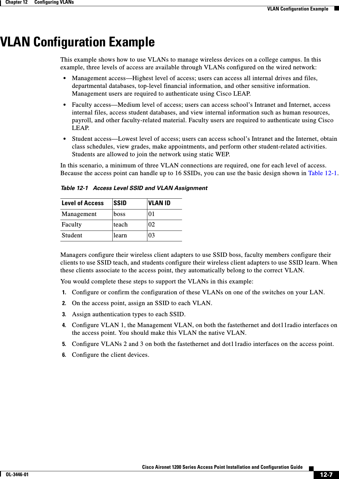
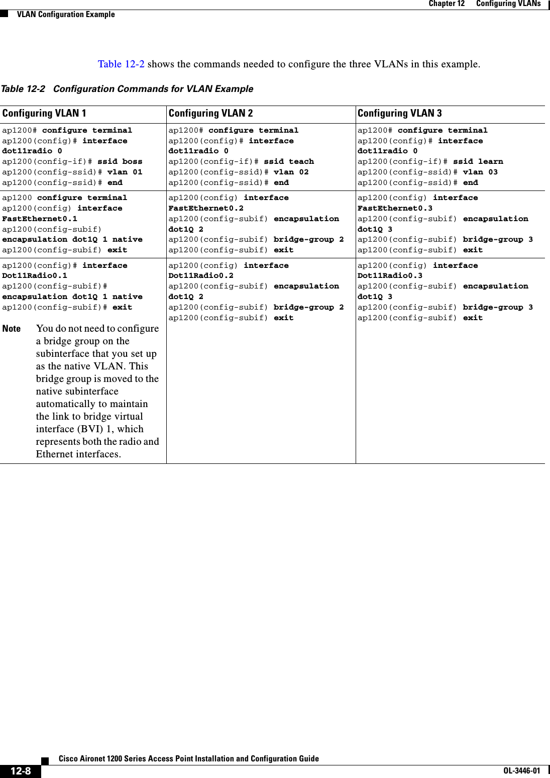
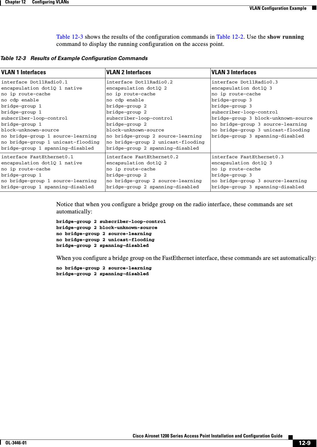

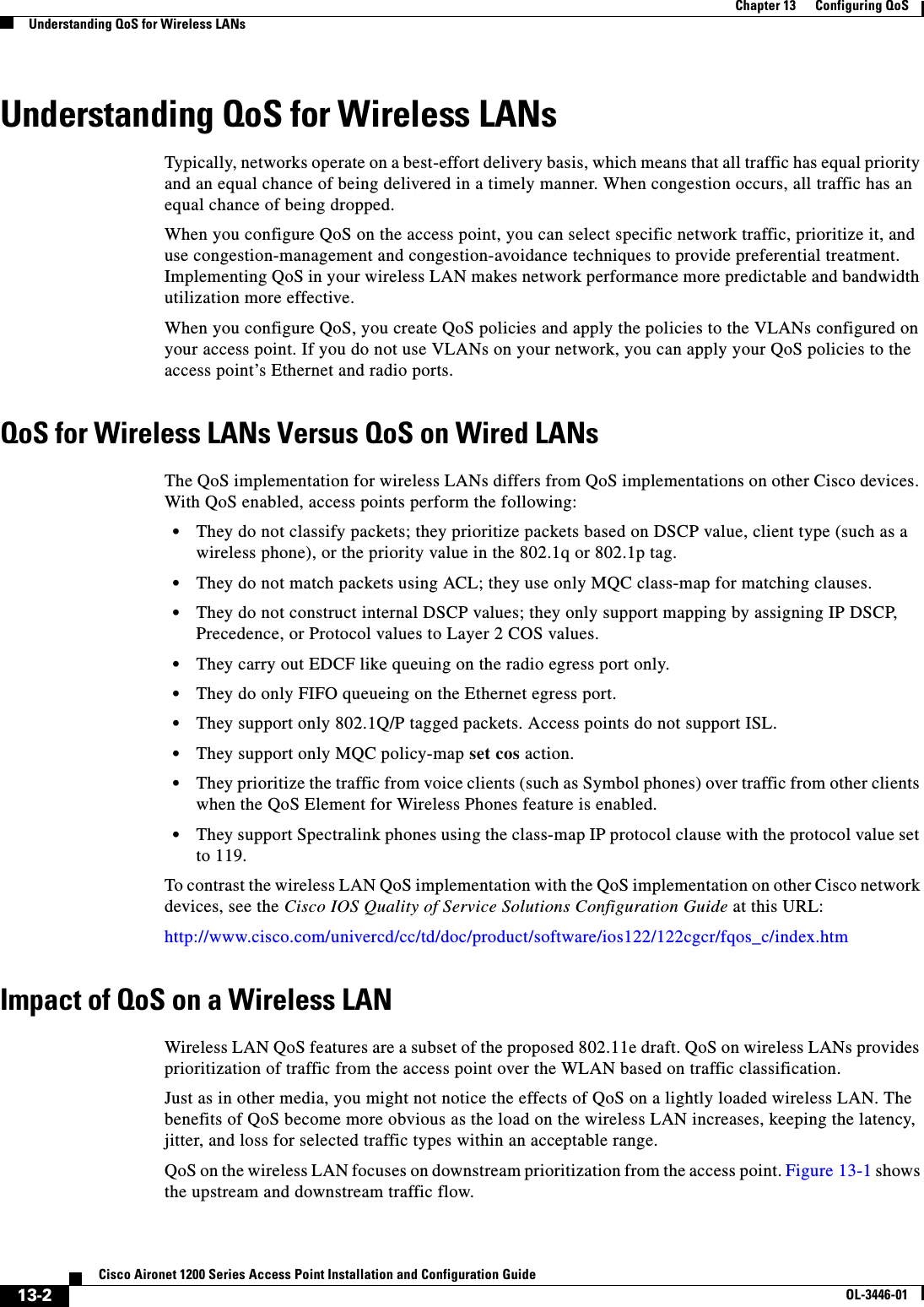
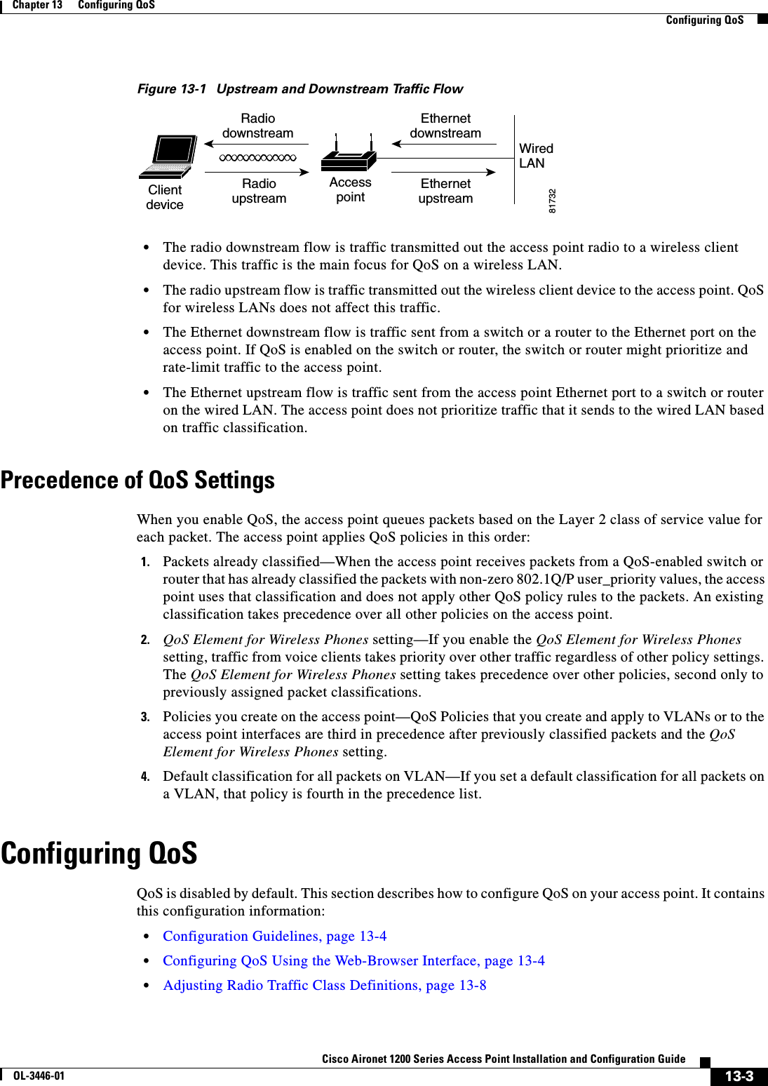
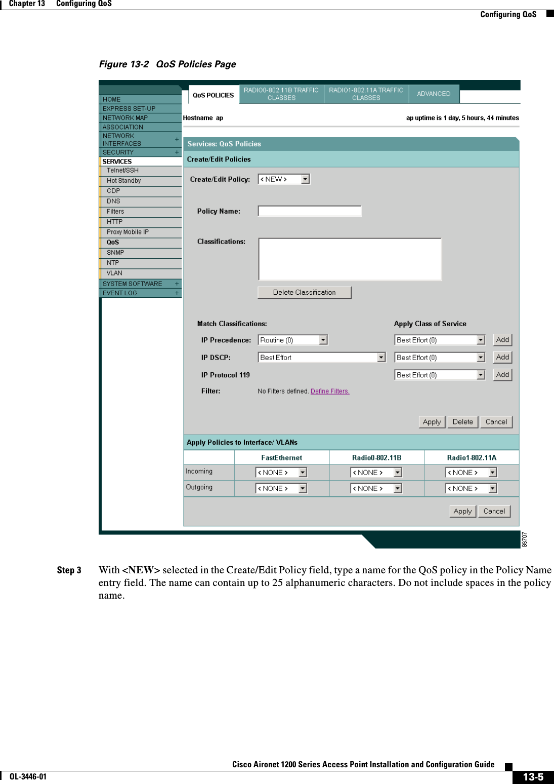
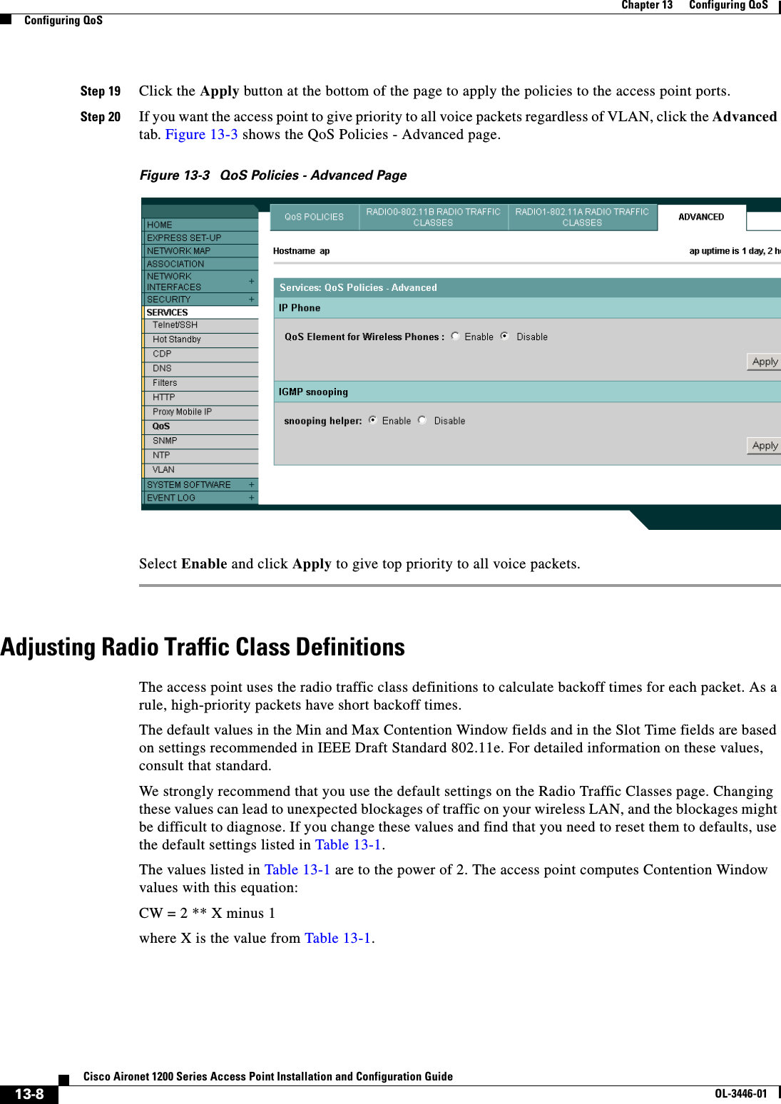
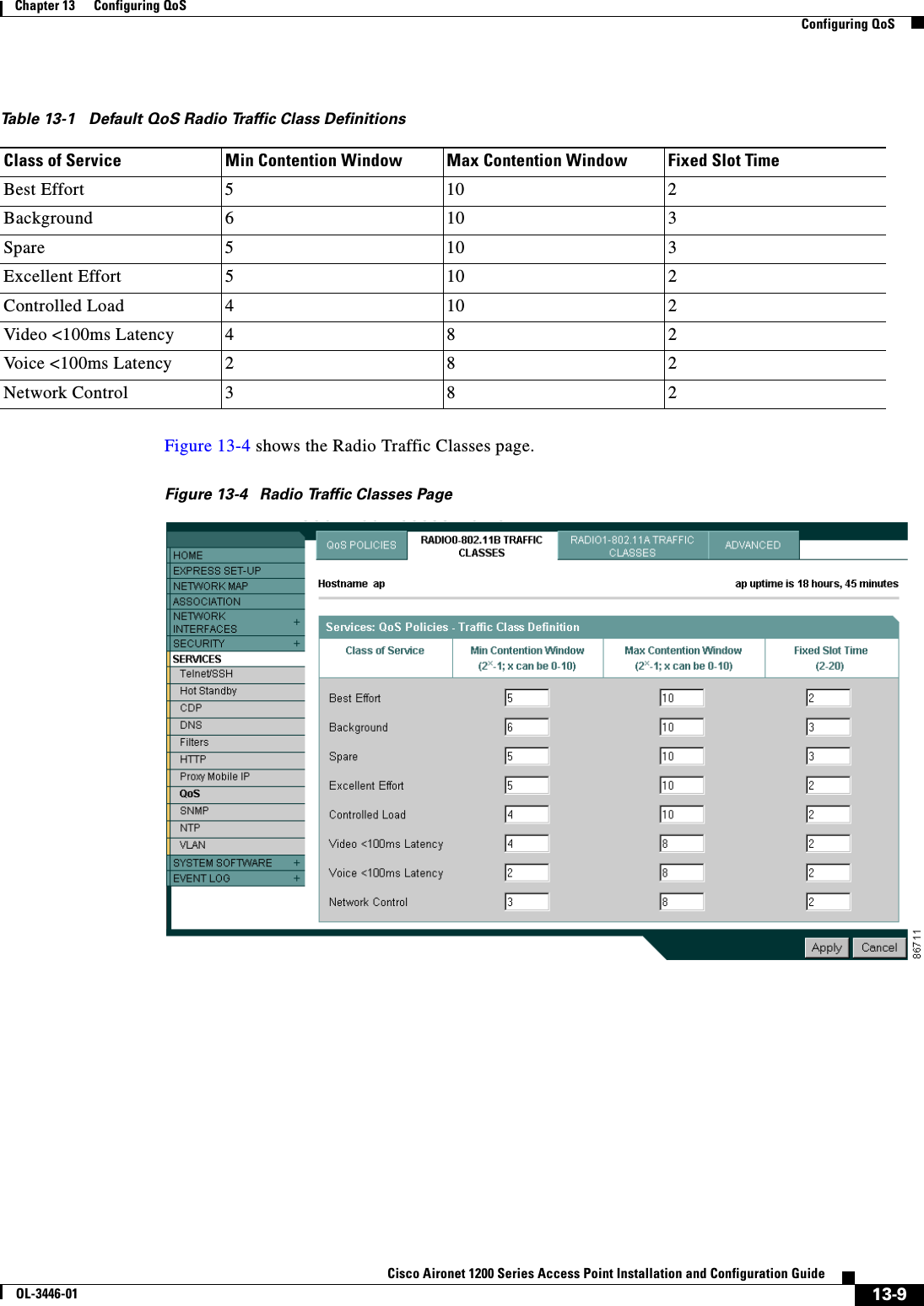
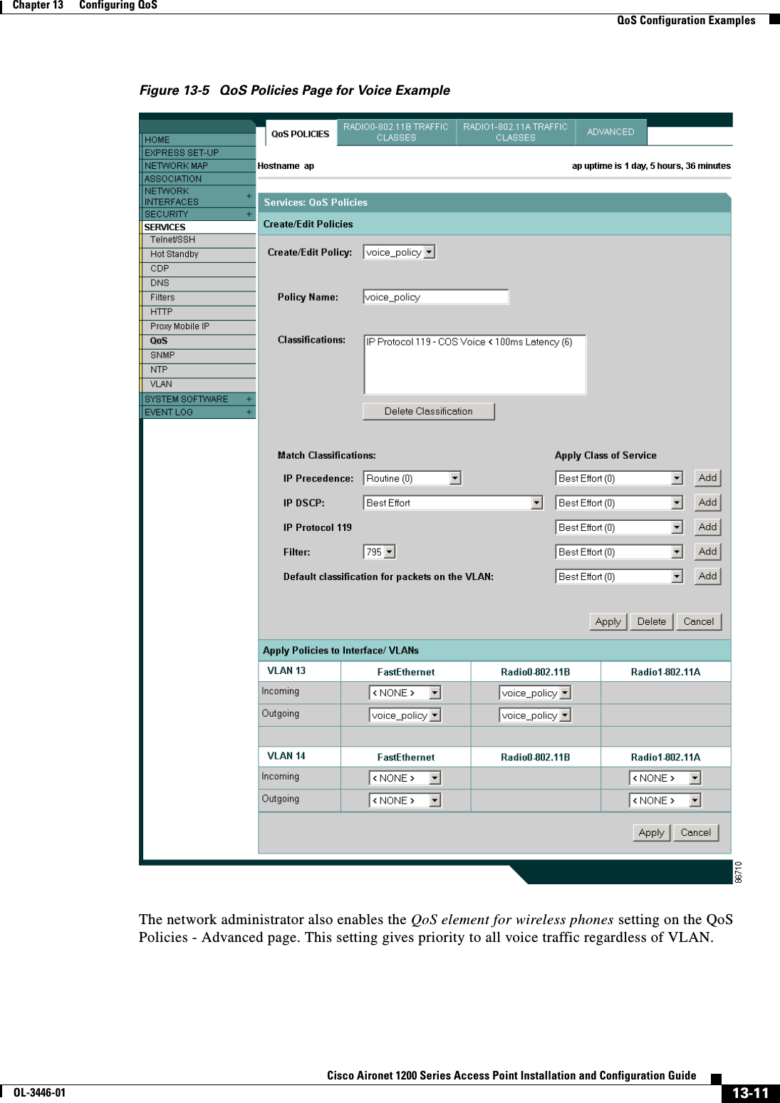
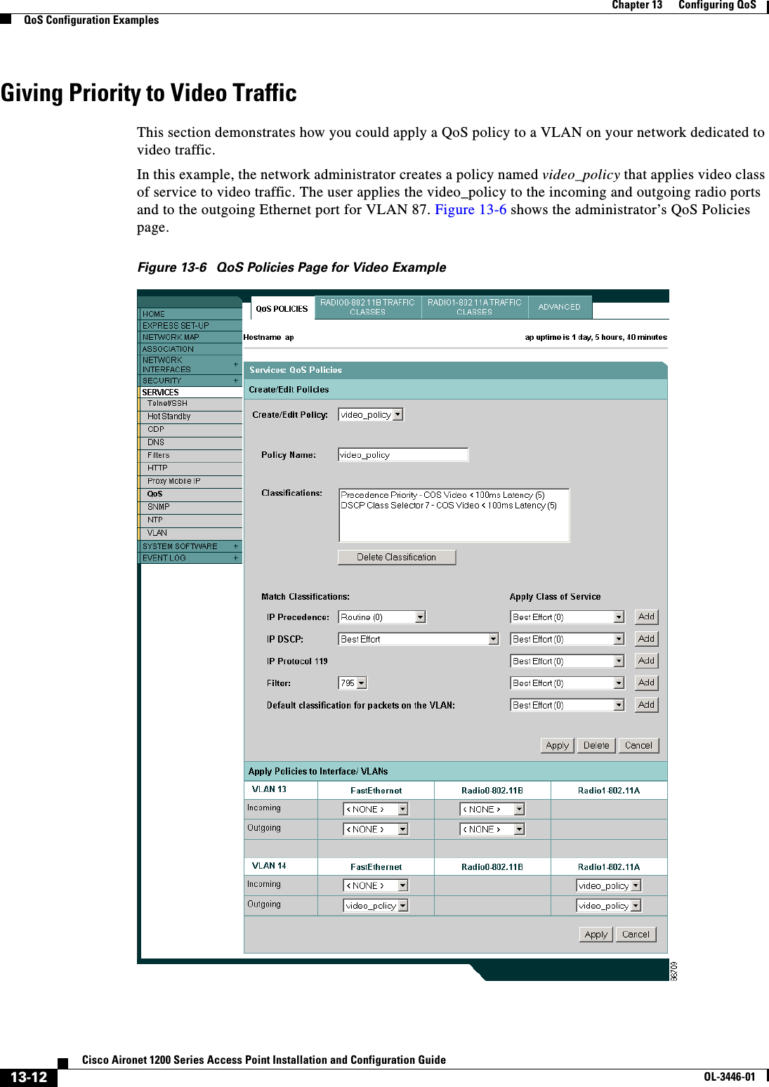
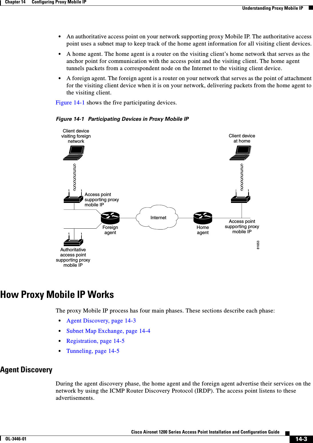
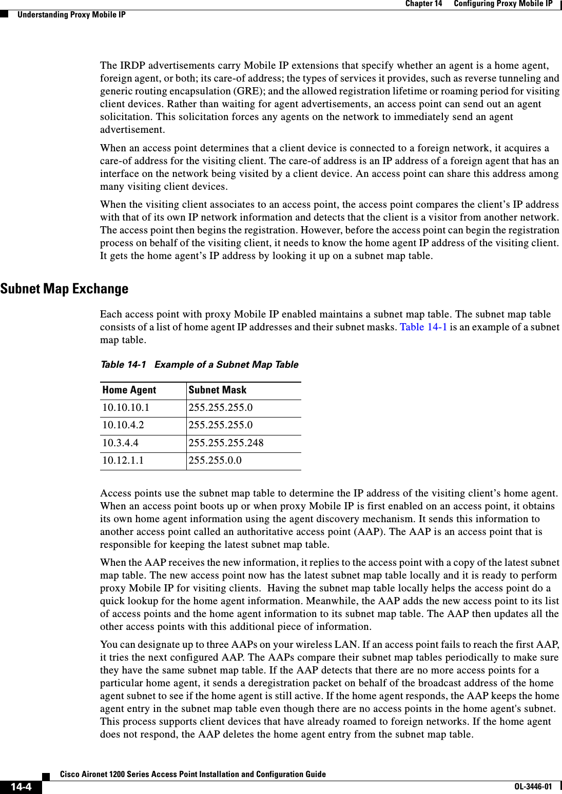
![14-7Cisco Aironet 1200 Series Access Point Installation and Configuration GuideOL-3446-01Chapter 14 Configuring Proxy Mobile IPConfiguring Proxy Mobile IP•To use proxy Mobile IP with DHCP-enabled client devices, you must disable Media Sense on the client devices. You can find instructions for disabling Media Sense in Microsoft Knowledge Base Article Q239924. Click this URL to browse to this article:http://support.microsoft.com/default.aspx?scid=KB;EN-US;Q239924&•Proxy Mobile IP does not support VLANs.•If you disable proxy Mobile IP on your access point, the entire proxy Mobile IP configuration is cleared. To disable proxy Mobile IP without clearing the configuration, use the ip proxy-mobile pause command.Configuring Proxy Mobile IP on Your Wired LANProxy Mobile IP on access points works in conjunction with Mobile IP configured on your network routers. For instructions on configuring Mobile IP on a router on your network, refer to the Mobile IP chapter in 12.2 T New Features (Early Deployment Releases). Click this link to browse to the Mobile IP chapter:http://www.cisco.com/univercd/cc/td/doc/product/software/ios120/120newft/120t/120t1/mobileip.htmConfiguring Proxy Mobile IP on Your Access PointBeginning in privileged EXEC mode, follow these steps to configure proxy Mobile IP on your access point:Command PurposeStep 1 configure terminal Enter global configuration mode.Step 2 ip proxy-mobile enable Enable proxy Mobile IP on the access point.Step 3 ip proxy-mobile aap ip-address[ip-address] [ip-address]Designate the access points that serve as the authoritative access points (the access points with which this access point compares its subnet table).Note You should specify at least two access points as AAPs in case one AAP fails. If you designate only one AAP and it goes offline, you lose all the information in the subnet map table.Step 4 ip proxy-mobile securenode address-start address-endspi spikey { hex | ascii } keyCreate security association settings for an IP address or for a range of IP addresses.•Enter an IP address, or the starting and ending addresses in an IP range.•Enter the security parameter index.•Enter a key for the security parameter. Specify whether the key contains hexadecimal or ASCII characters. If you choose hexadecimal, the key must contain 32 characters. If you choose ASCII, the key can contain up to 16 characters with no minimum length.Step 5 interface fastethernet 0 Enter interface configuration mode for the Ethernet port.Step 6 ip proxy-mobile Enable proxy Mobile IP on the Ethernet port.](https://usermanual.wiki/Cisco-Systems/102053.CRN-27004-Question-6-AP-user-manual/User-Guide-441628-Page-195.png)
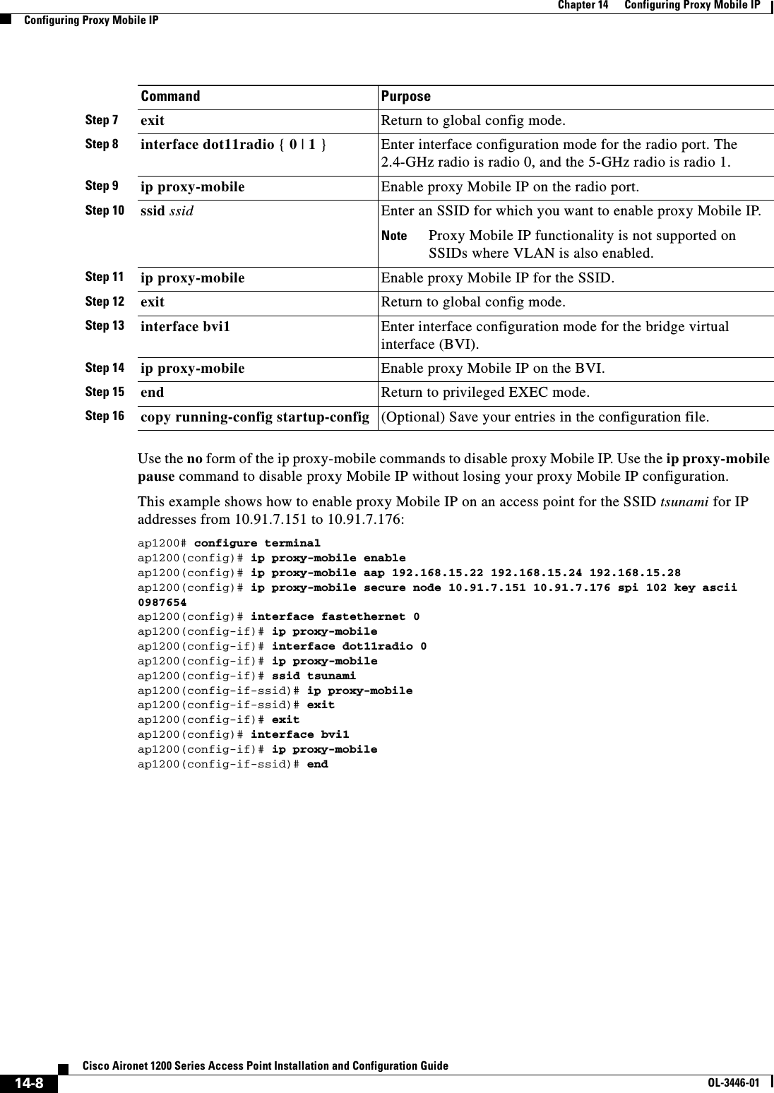
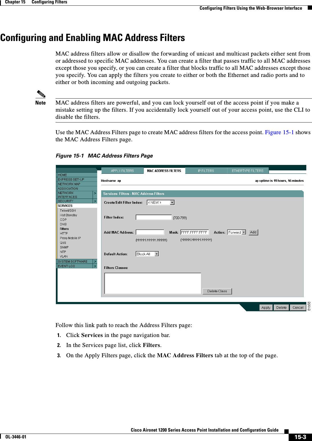
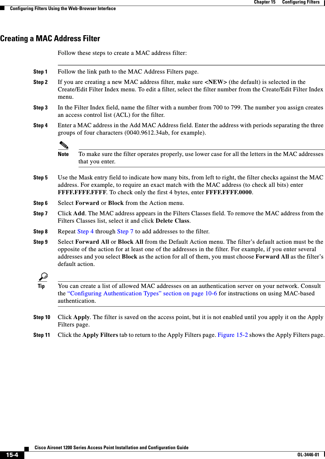
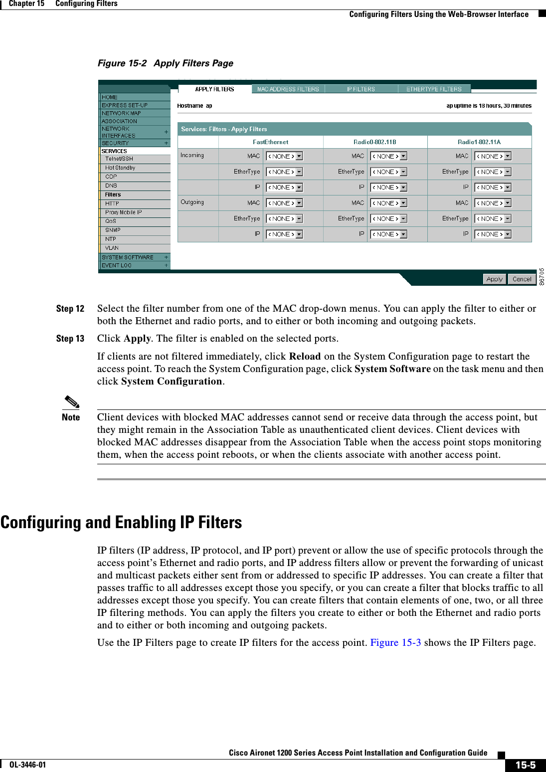
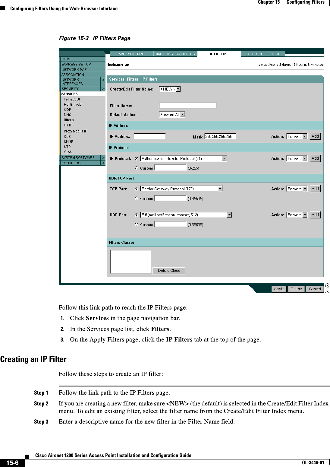
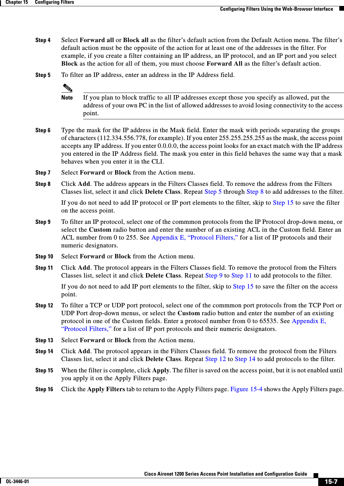
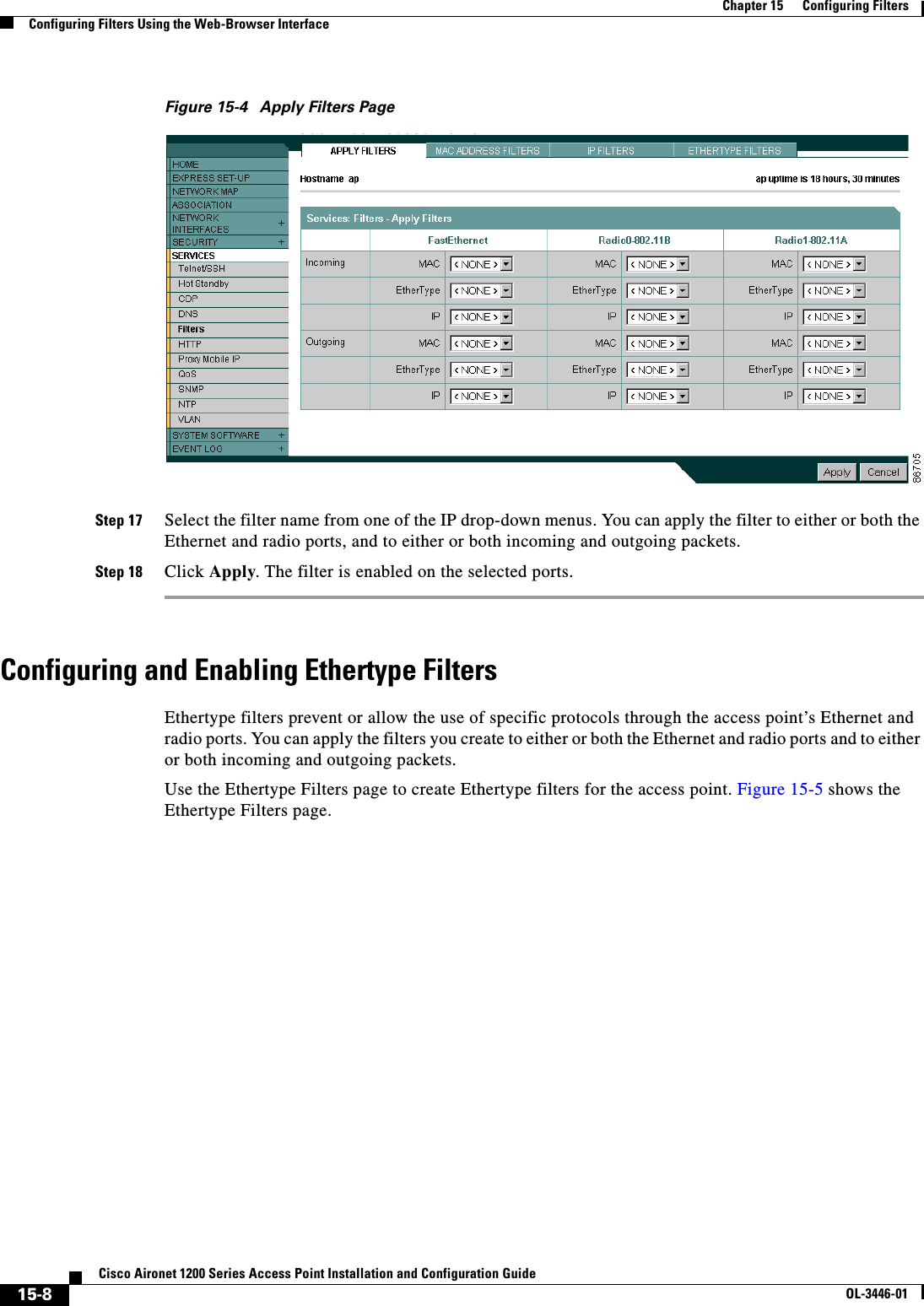
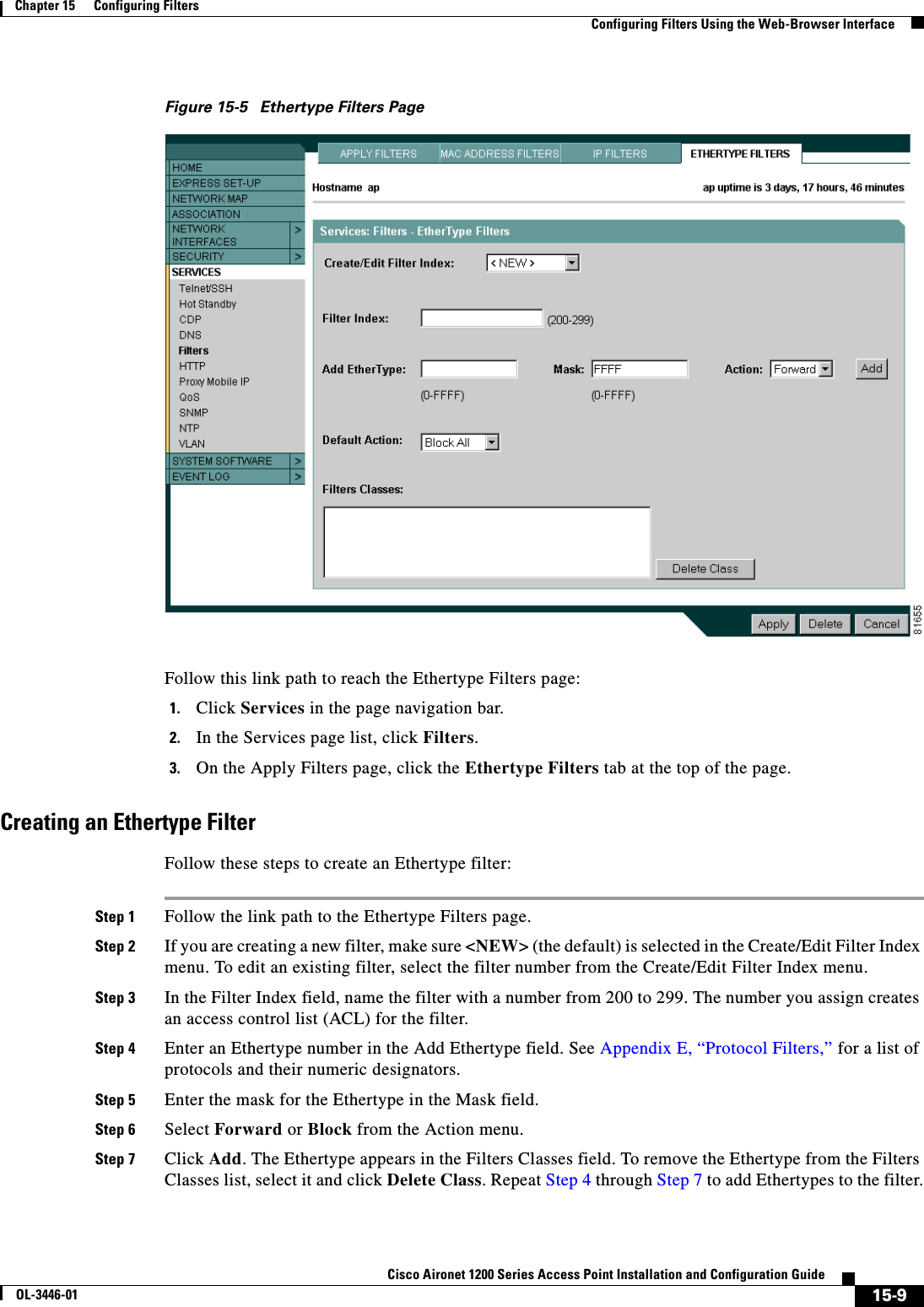
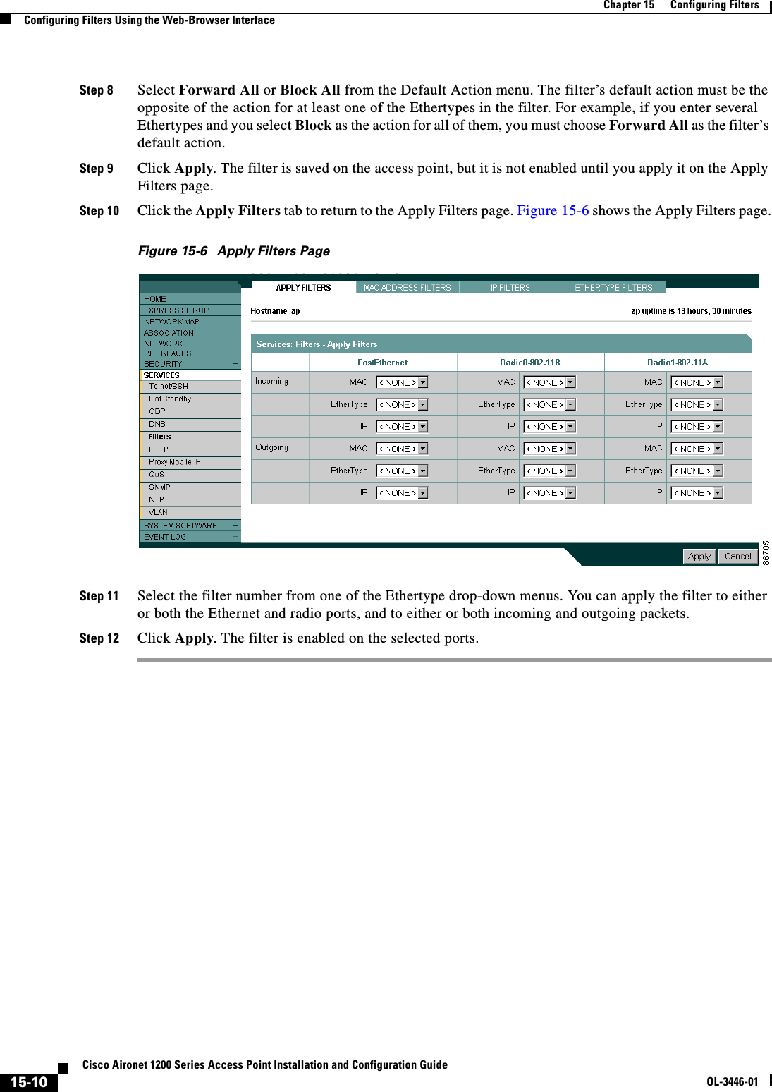
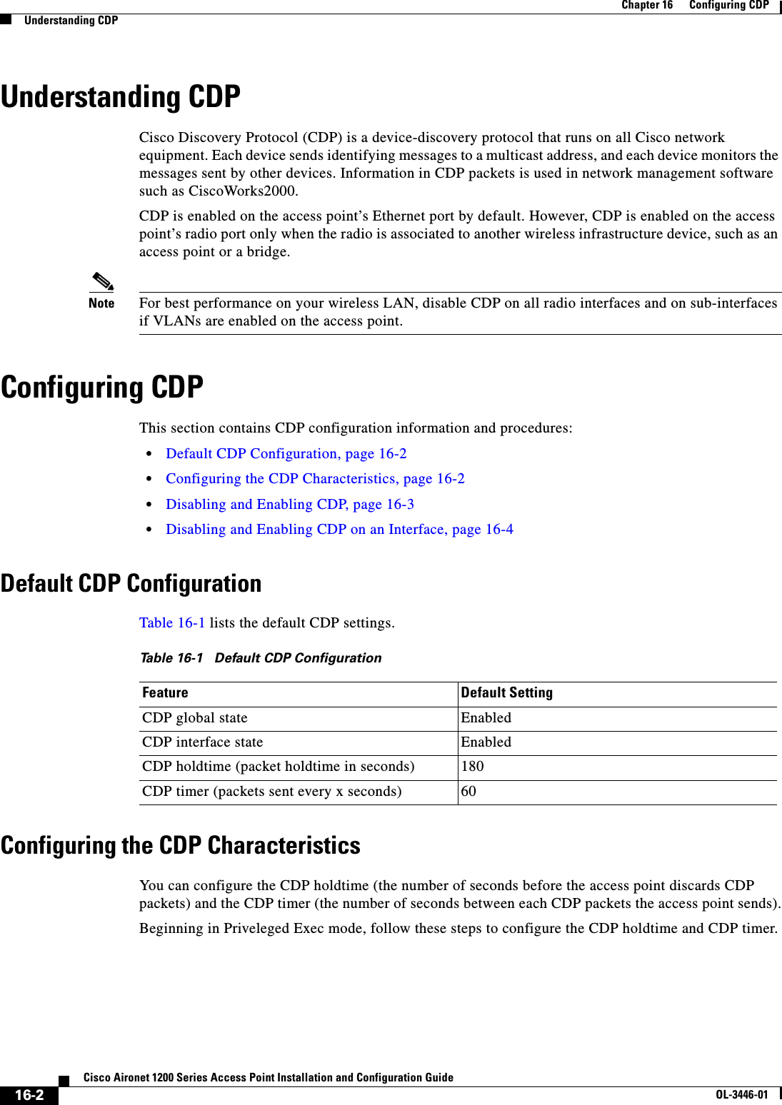
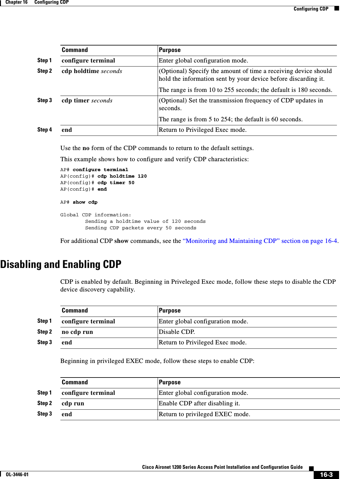
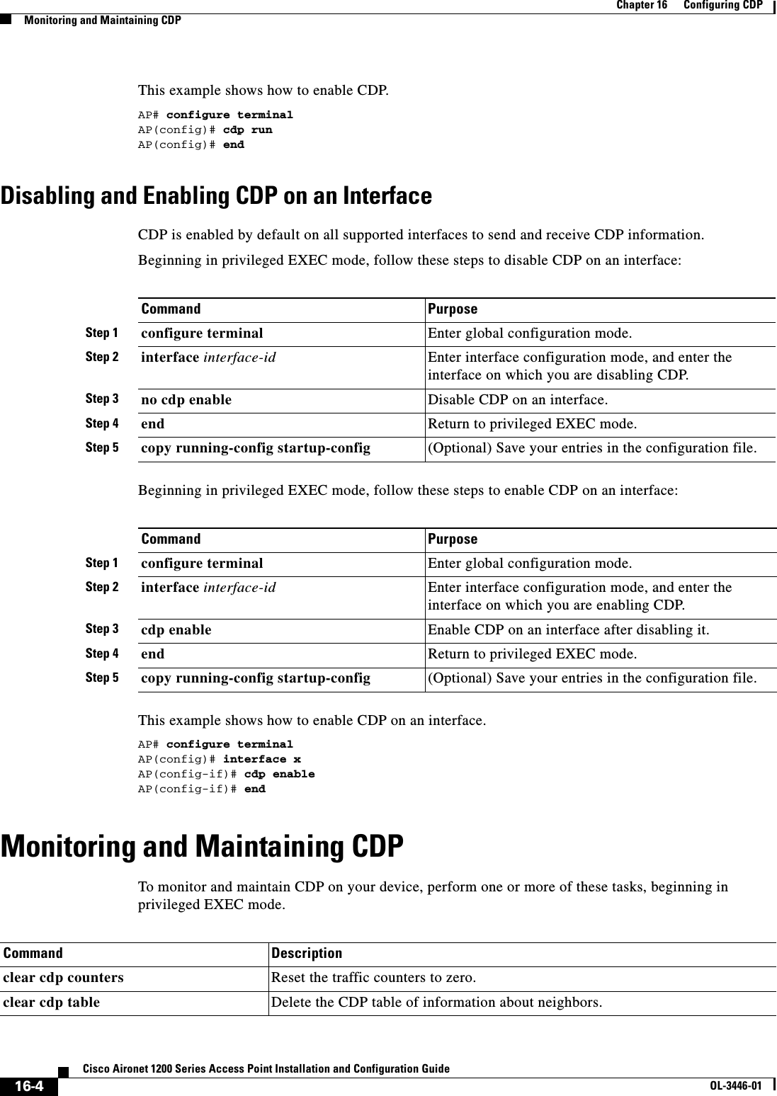
![16-5Cisco Aironet 1200 Series Access Point Installation and Configuration GuideOL-3446-01Chapter 16 Configuring CDPMonitoring and Maintaining CDPBelow are six examples of output from the CDP show privileged EXEC commands:AP# show cdpGlobal CDP information: Sending CDP packets every 50 seconds Sending a holdtime value of 120 secondsAP# show cdp entry *-------------------------Device ID: APEntry address(es): IP address: 10.1.1.66Platform: cisco WS-C3550-12T, Capabilities: Switch IGMPInterface: GigabitEthernet0/2, Port ID (outgoing port): GigabitEthernet0/2Holdtime : 129 secVersion :Cisco Internetwork Operating System SoftwareIOS (tm) C3550 Software (C3550-I5Q3L2-M), Experimental Version 12.1(20010612:021316) [jang-flamingo 120]Copyright (c) 1986-2001 by cisco Systems, Inc.Compiled Fri 06-Jul-01 18:18 by jangadvertisement version: 2Protocol Hello: OUI=0x00000C, Protocol ID=0x0112; payload len=27, value=00000000FFFFFFFF010221FF00000000000000024B293A00FF0000VTP Management Domain: ''Duplex: full-------------------------Device ID: idf2-1-lab-l3.cisco.comEntry address(es): IP address: 10.1.1.10Platform: cisco WS-C3524-XL, Capabilities: Trans-Bridge Switchshow cdp Display global information, such as frequency of transmissions and the holdtime for packets being sent.show cdp entry entry-name [protocol |version]Display information about a specific neighbor. You can enter an asterisk (*) to display all CDP neighbors, or you can enter the name of the neighbor about which you want information.You can also limit the display to information about the protocols enabled on the specified neighbor or information about the version of software running on the device.show cdp interface [type number] Display information about interfaces where CDP is enabled.You can limit the display to the type of interface or the number of the interface about which you want information (for example, entering gigabitethernet 0/1 displays information only about Gigabit Ethernet port 1).show cdp neighbors [type number][detail]Display information about neighbors, including device type, interface type and number, holdtime settings, capabilities, platform, and port ID. You can limit the display to neighbors on a specific type or number of interface or expand the display to provide more detailed information.show cdp traffic Display CDP counters, including the number of packets sent and received and checksum errors.Command Description](https://usermanual.wiki/Cisco-Systems/102053.CRN-27004-Question-6-AP-user-manual/User-Guide-441628-Page-211.png)
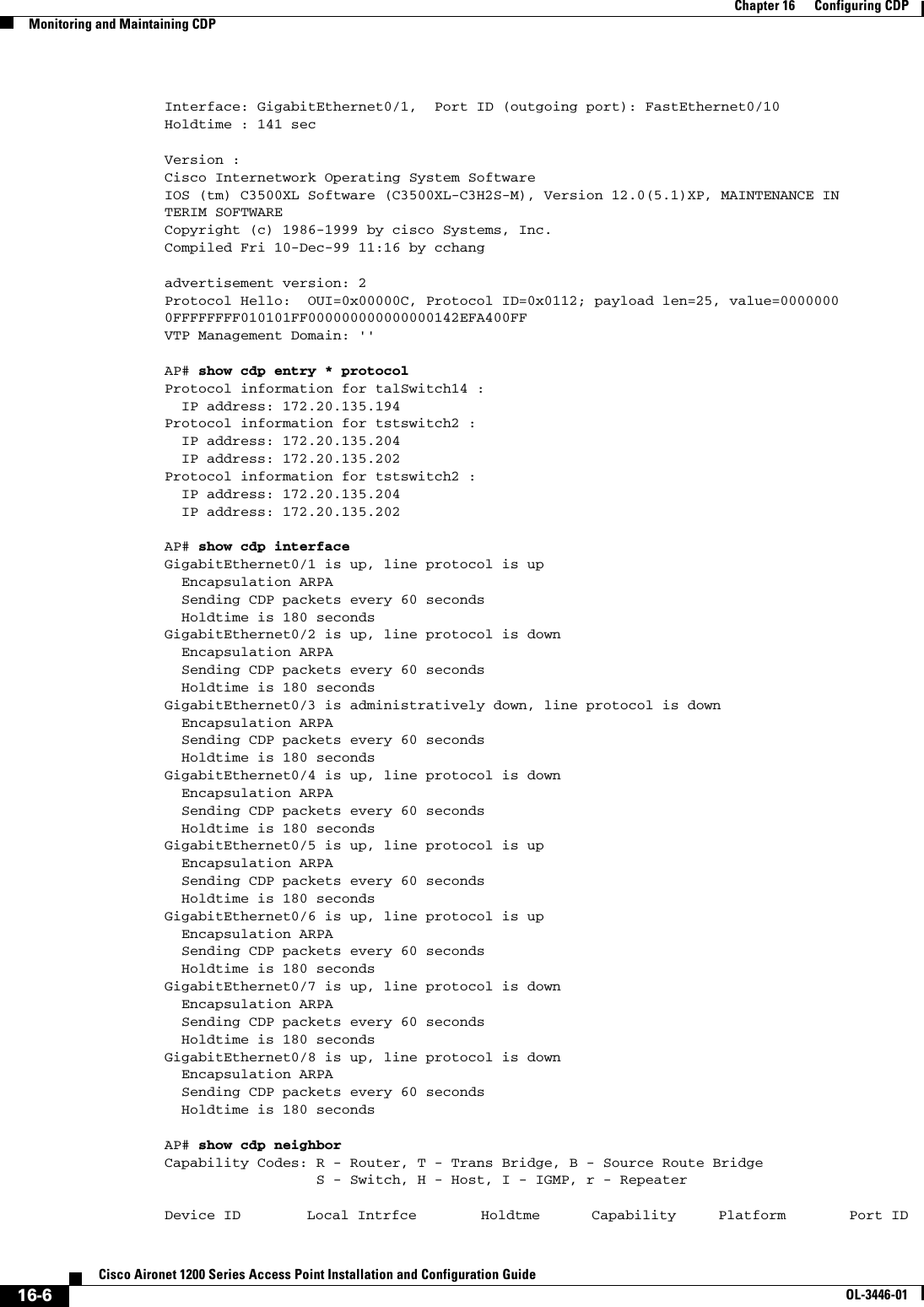

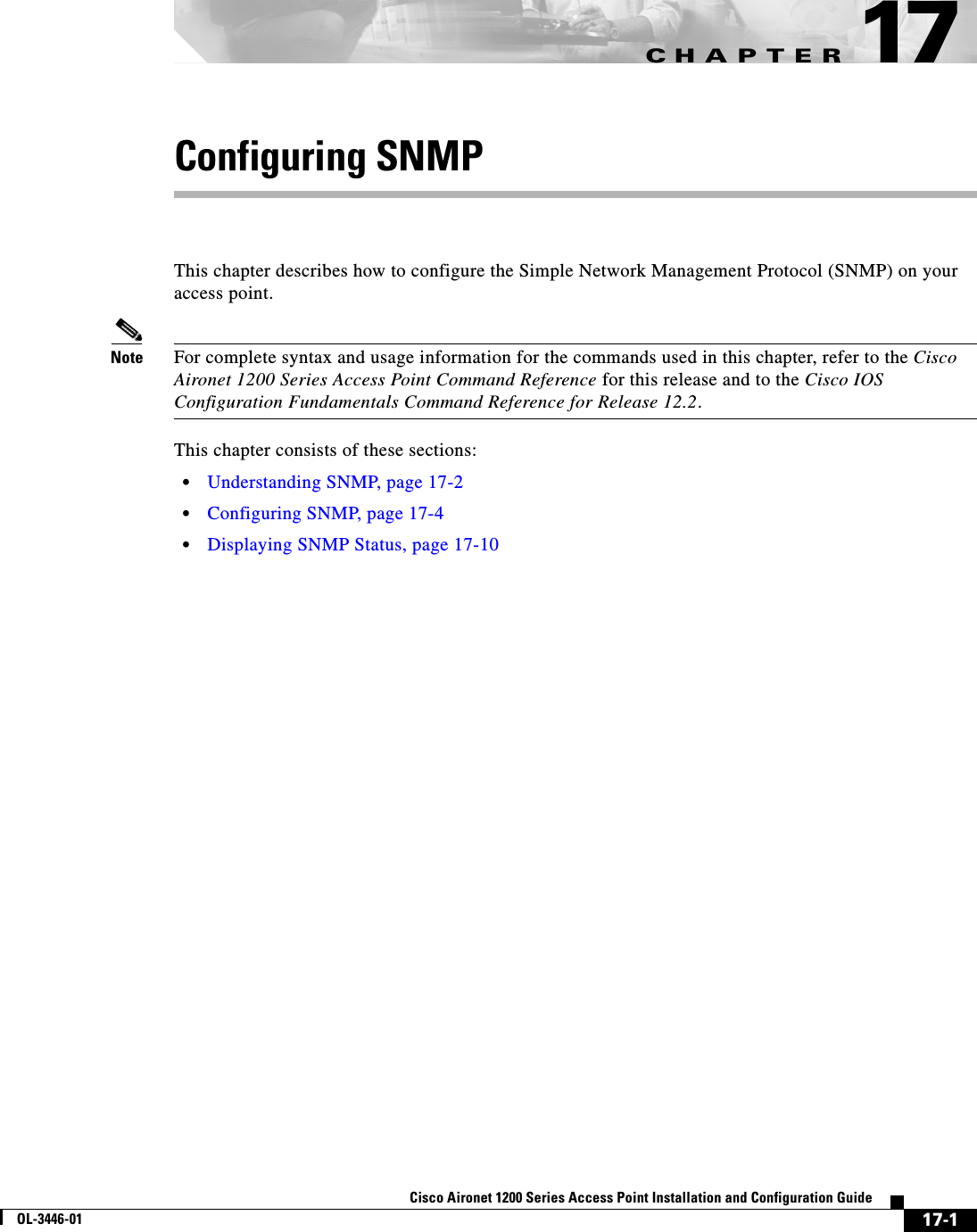
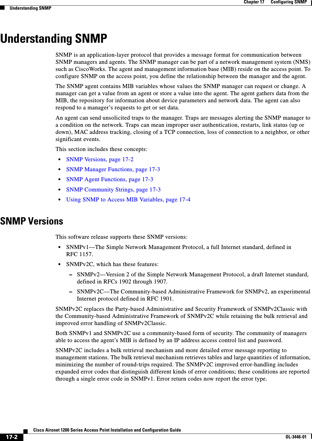
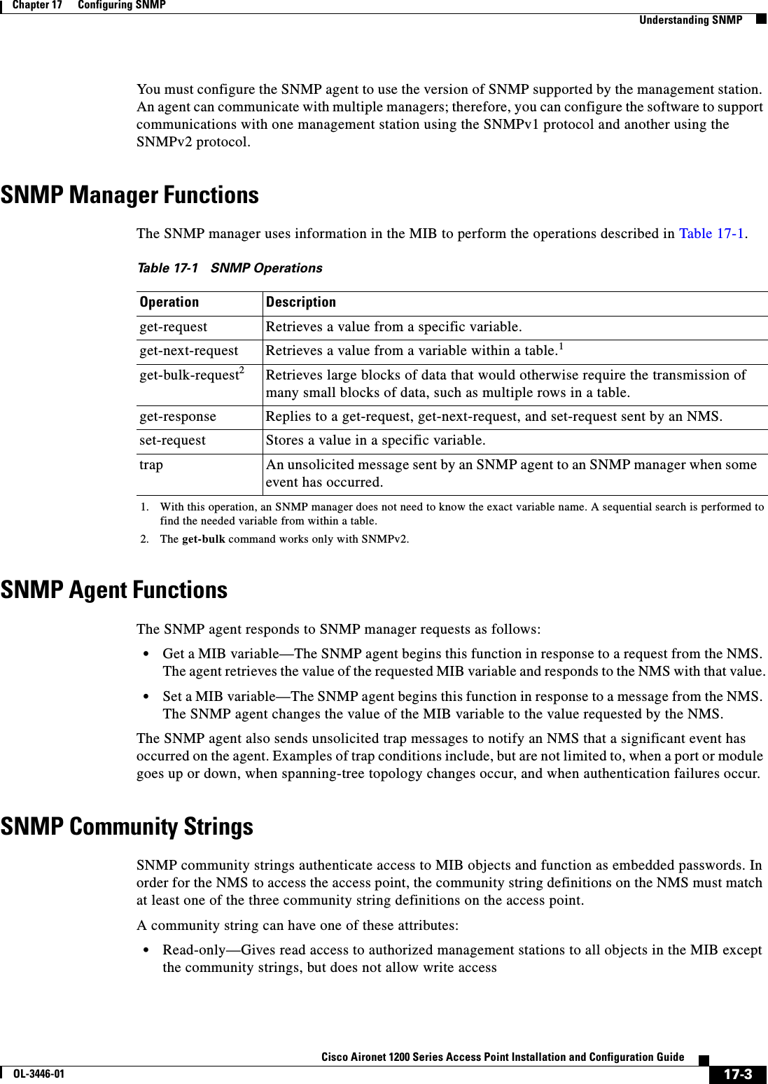
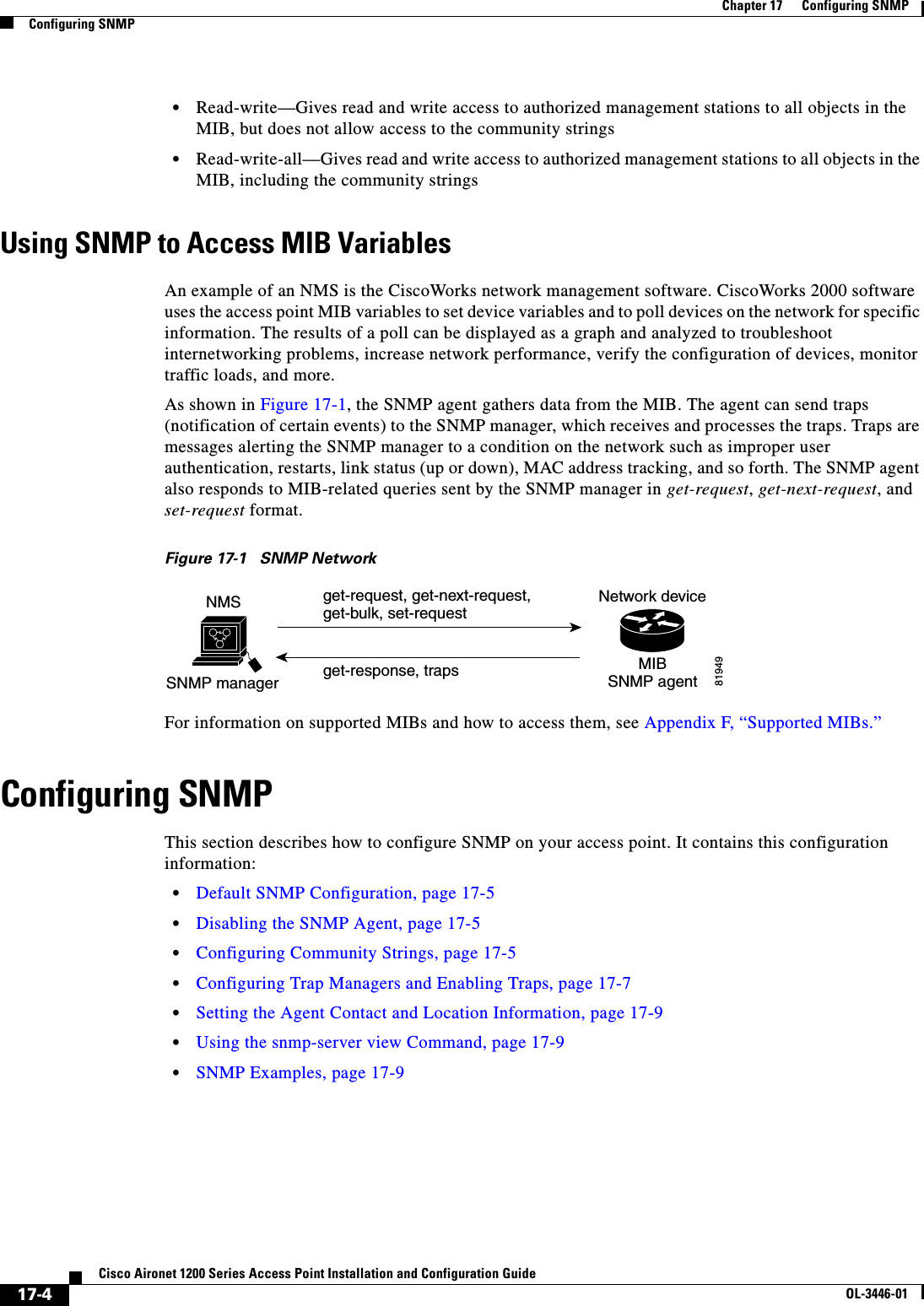
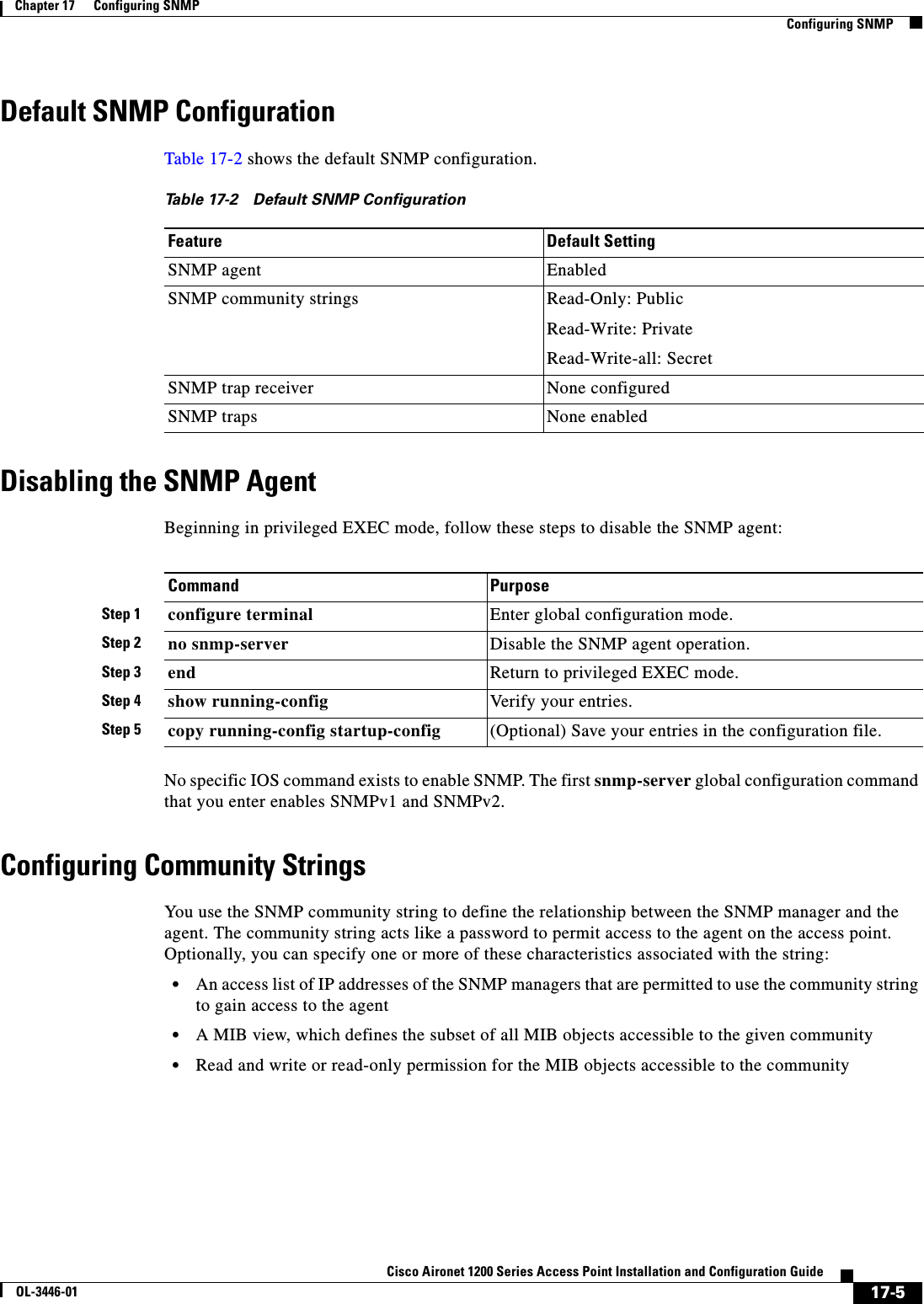
![17-6Cisco Aironet 1200 Series Access Point Installation and Configuration GuideOL-3446-01Chapter 17 Configuring SNMPConfiguring SNMPBeginning in privileged EXEC mode, follow these steps to configure a community string on the access point:Note To disable access for an SNMP community, set the community string for that community to the null string (do not enter a value for the community string).To remove a specific community string, use the no snmp-server community string global configuration command. This example shows how to assign the string comaccess to SNMP, to allow read-only access, and to specify that IP access list 4 can use the community string to gain access to the access point SNMP agent:AP(config)# snmp-server community comaccess ro 4Command PurposeStep 1 configure terminal Enter global configuration mode.Step 2 snmp-server community string [ro |rw][access-list-number]Configure the community string.•For string, specify a string that acts like a password and permits access to the SNMP protocol. You can configure one or more community strings of any length.•(Optional) Specify either read-only (ro) if you want authorized management stations to retrieve MIB objects, or specify read/write (rw) if you want authorized management stations to retrieve and modify MIB objects. By default, the community string permits read-only access to all objects.•(Optional) For access-list-number, enter an IP standard access list numbered from 1 to 99 and 1300 to 1999.Step 3 access-list access-list-number {deny | permit}source [source-wildcard](Optional) If you specified an IP standard access list number in Step 2, then create the list, repeating the command as many times as necessary.•For access-list-number, enter the access list number specified in Step 2.•The deny keyword denies access if the conditions are matched. The permit keyword permits access if the conditions are matched.•For source, enter the IP address of the SNMP managers that are permitted to use the community string to gain access to the agent.•(Optional) For source-wildcard, enter the wildcard bits in dotted decimal notation to be applied to the source. Place ones in the bit positions that you want to ignore.Recall that the access list is always terminated by an implicit deny statement for everything.Step 4 end Return to privileged EXEC mode.Step 5 show running-config Verify your entries.Step 6 copy running-config startup-config (Optional) Save your entries in the configuration file.](https://usermanual.wiki/Cisco-Systems/102053.CRN-27004-Question-6-AP-user-manual/User-Guide-441628-Page-220.png)
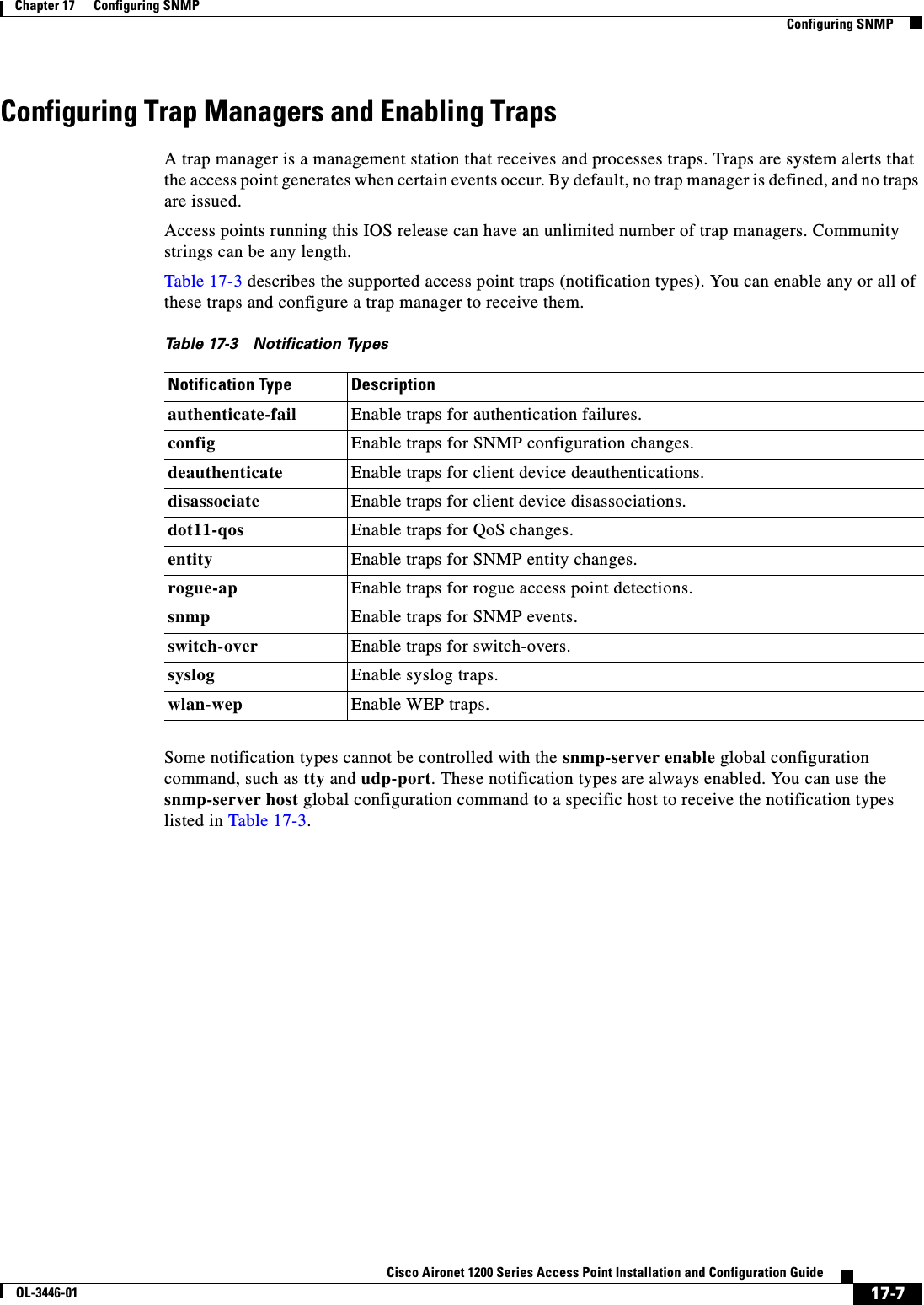
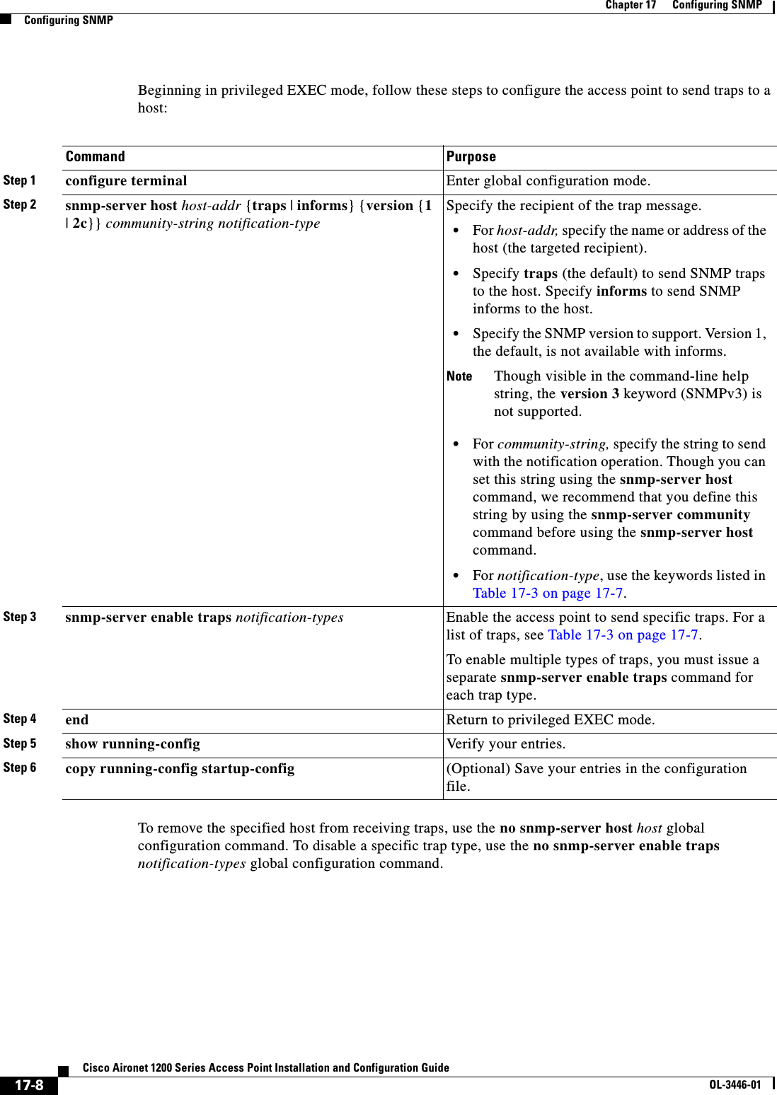
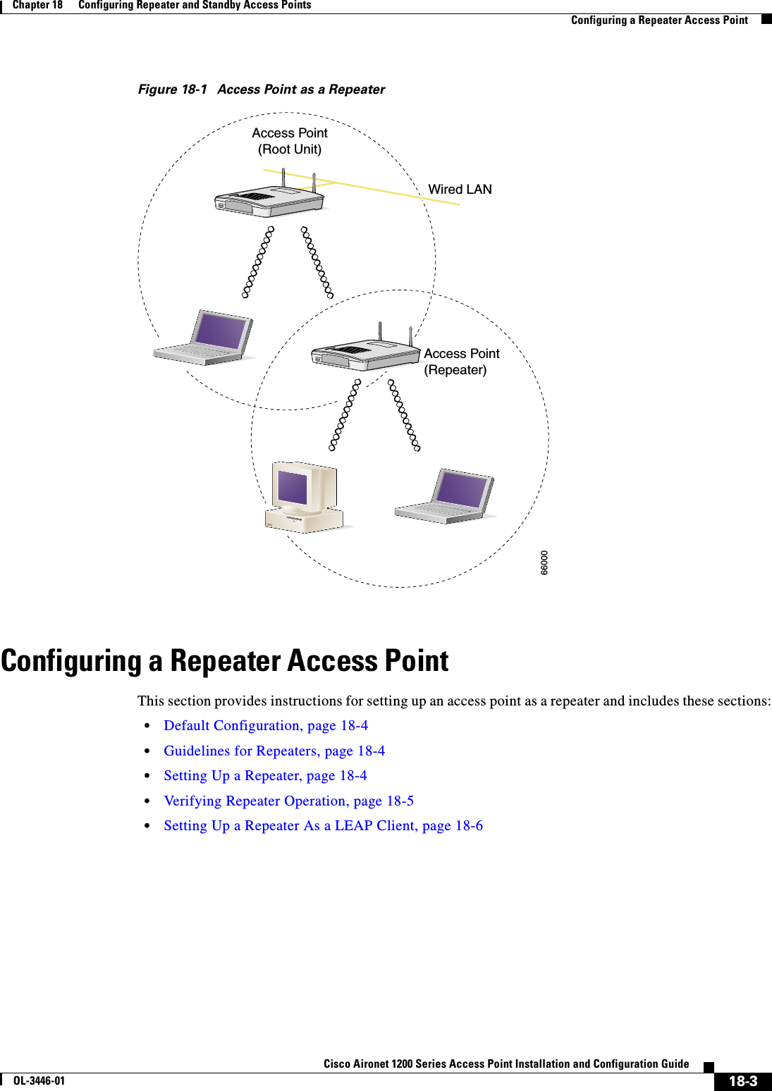
![18-4Cisco Aironet 1200 Series Access Point Installation and Configuration GuideOL-3446-01Chapter 18 Configuring Repeater and Standby Access PointsConfiguring a Repeater Access PointDefault ConfigurationAccess points are configured as root units by default. Table 18-1 shows the default values for settings that control the access point’s role in the wireless LAN.Guidelines for RepeatersFollow these guidelines when configuring repeater access points:•Use repeaters to serve client devices that do not require high throughput. Repeaters extend the coverage area of your wireless LAN, but they drastically reduce throughput.•Use repeaters when most if not all client devices that associate with the repeaters are Cisco Aironet clients. Non-Cisco client devices sometimes have trouble communicating with repeater access points.Setting Up a RepeaterBeginning in Privileged Exec mode, follow these steps to configure an access point as a repeater:Table 18-1 Default Settings for Role in Wireless LANFeature Default SettingStation role RootParent noneExtensions AironetCommand PurposeStep 1 configure terminal Enter global configuration mode.Step 2 interface dot11radio { 0 | 1 } Enter interface configuration mode for the radio interface. The 2.4-GHz radio is radio 0, and the 5-GHz radio is radio 1.Step 3 ssid ssid-string Create the SSID that the repeater uses to associate to a root access point; in the next step designate this SSID as an infrastructure SSID. If you created an infrastructure SSID on the root access point, create the same SSID on the repeater, also.Step 4 infrastructure-ssid [optional] Designate the SSID as an infrastructure SSID. The repeater uses this SSID to associate to the root access point. Infrastructure devices must associate to the repeater access point using this SSID unless you also enter the optional keyword.Step 5 exit Exit SSID configuration mode and return to radio interface configuration mode.Step 6 station-role repeater Set the access point’s role in the wireless LAN to repeater.Step 7 dot11 extensions aironet If Aironet extensions are disabled, enable Aironet extensions.](https://usermanual.wiki/Cisco-Systems/102053.CRN-27004-Question-6-AP-user-manual/User-Guide-441628-Page-228.png)
 Enter the MAC address for the access point to which the repeater should associate. •You can enter MAC addresses for up to four parent access points. The repeater attempts to associate to MAC address 1 first; if that access point does not respond, the repeater tries the next access point in its parent list. •(Optional) You can also enter a timeout value in seconds that determines how long the repeater attempts to associate to a parent access point before trying the next parent in the list. Enter a timeout value from 0 to 65535 seconds.Step 9 end Return to privileged EXEC mode.Step 10 copy running-config startup-config(Optional) Save your entries in the configuration file.Command Purpose](https://usermanual.wiki/Cisco-Systems/102053.CRN-27004-Question-6-AP-user-manual/User-Guide-441628-Page-229.png)
![18-6Cisco Aironet 1200 Series Access Point Installation and Configuration GuideOL-3446-01Chapter 18 Configuring Repeater and Standby Access PointsConfiguring a Repeater Access PointSetting Up a Repeater As a LEAP ClientYou can set up a repeater access point to authenticate to your network like other wireless client devices. After you provide a network username and password for the repeater access point, it authenticates to your network using LEAP, Cisco's wireless authentication method, and receives and uses dynamic WEP keys. Setting up a repeater as a LEAP client requires three major steps:1. Create an authentication username and password for the repeater on your authentication server.2. Configure LEAP authentication on the root access point to which the repeater associates. See Chapter 10, “Configuring Authentication Types,” for instructions on setting up authentication on the access point.3. Configure the repeater to act as a LEAP client. Beginning in Privileged Exec mode, follow these instructions to set up the repeater as a LEAP client:Command PurposeStep 1 configure terminal Enter global configuration mode.Step 2 interface dot11radio { 0 | 1 } Enter interface configuration mode for the radio interface. The 2.4-GHz radio is radio 0, and the 5-GHz radio is radio 1.Step 3 ssid ssid-string Create an SSID and enter SSID configuration mode for the new SSID. The SSID can consist of up to 32 alphanumeric characters, but they should not include spaces. SSIDs are case-sensitive.Step 4 authentication network-eap list-nameEnable LEAP authentication on the repeater so that LEAP-enabled client devices can authenticate through the repeater. For list-name, specify the name or IP address of the authentication server.Step 5 authentication client username username password passwordConfigure the username and password that the repeater uses when it performs LEAP authentication. This username and password must match the username and password that you set up for the repeater on the authentication server.Step 6 infrastructure ssid [optional] (Optional) Designate the SSID as the SSID that other access points and workgroup bridges use to associate to this access point. If you do not designate an SSID as the infrastructure SSID, infrastructure devices can associate to the access point using any SSID. If you designate an SSID as the infrastructure SSID, infrastructure devices must associate to the access point using that SSID unless you also enter the optional keyword.Step 7 end Return to privileged EXEC mode.Step 8 copy running-config startup-config(Optional) Save your entries in the configuration file.](https://usermanual.wiki/Cisco-Systems/102053.CRN-27004-Question-6-AP-user-manual/User-Guide-441628-Page-230.png)
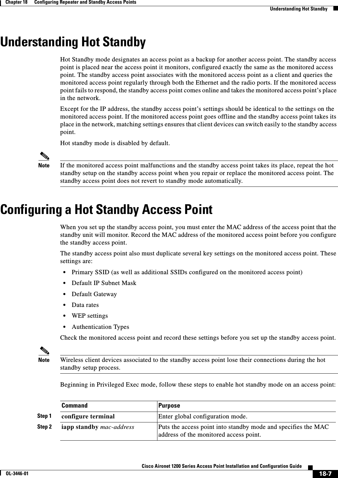
![18-8Cisco Aironet 1200 Series Access Point Installation and Configuration GuideOL-3446-01Chapter 18 Configuring Repeater and Standby Access PointsConfiguring a Hot Standby Access PointAfter you enable standby mode, configure the settings that you recorded from the monitored access point to match on the standby access point. Use this command to check the standby configuration:show iapp standby-parmsThis command displays the MAC address of the standby access point, the standby timeout, and the poll-frequency values. If no standby access point is configured, this message appears:no iapp standby mac-addressStep 3 interface dot11radio 0 Enter interface configuration mode for the radio interface.Note Hot Standby mode is available only for the 2.4-GHz radio.Step 4 ssid ssid-string Create the SSID that the standby access point uses to associate to the monitored access point; in the next step designate this SSID as an infrastructure SSID. If you created an infrastructure SSID on the monitored access point, create the same SSID on the repeater, also.Step 5 infrastructure-ssid [optional] Designate the SSID as an infrastructure SSID. The standby uses this SSID to associate to the monitored access point. If the standby access point takes the place of the monitored access point, infrastructure devices must associate to the standby access point using this SSID unless you also enter the optional keyword.Step 6 exit Exit SSID configuration mode and return to radio interface configuration mode.Step 7 iapp standby poll-frequencysecondsSets the number of seconds between queries that the standby access point sends to the monitored access point’s radio and Ethernet ports.Step 8 iapp standby timeout seconds Sets the number of seconds the standby access point waits for a response from the monitored access point before it assumes that the monitored access point has malfunctioned.Step 9 show iapp standby-parms Verify your entries. If the access point is in standby mode, this command displays the standby parameters, including the MAC address of the monitored access point and the poll-frequency and timeout values. If the access point is not in standby mode, no iapp standby mac-address appears.Step 10 end Return to privileged EXEC mode.Step 11 copy running-config startup-config(Optional) Save your entries in the configuration file.Command Purpose](https://usermanual.wiki/Cisco-Systems/102053.CRN-27004-Question-6-AP-user-manual/User-Guide-441628-Page-232.png)
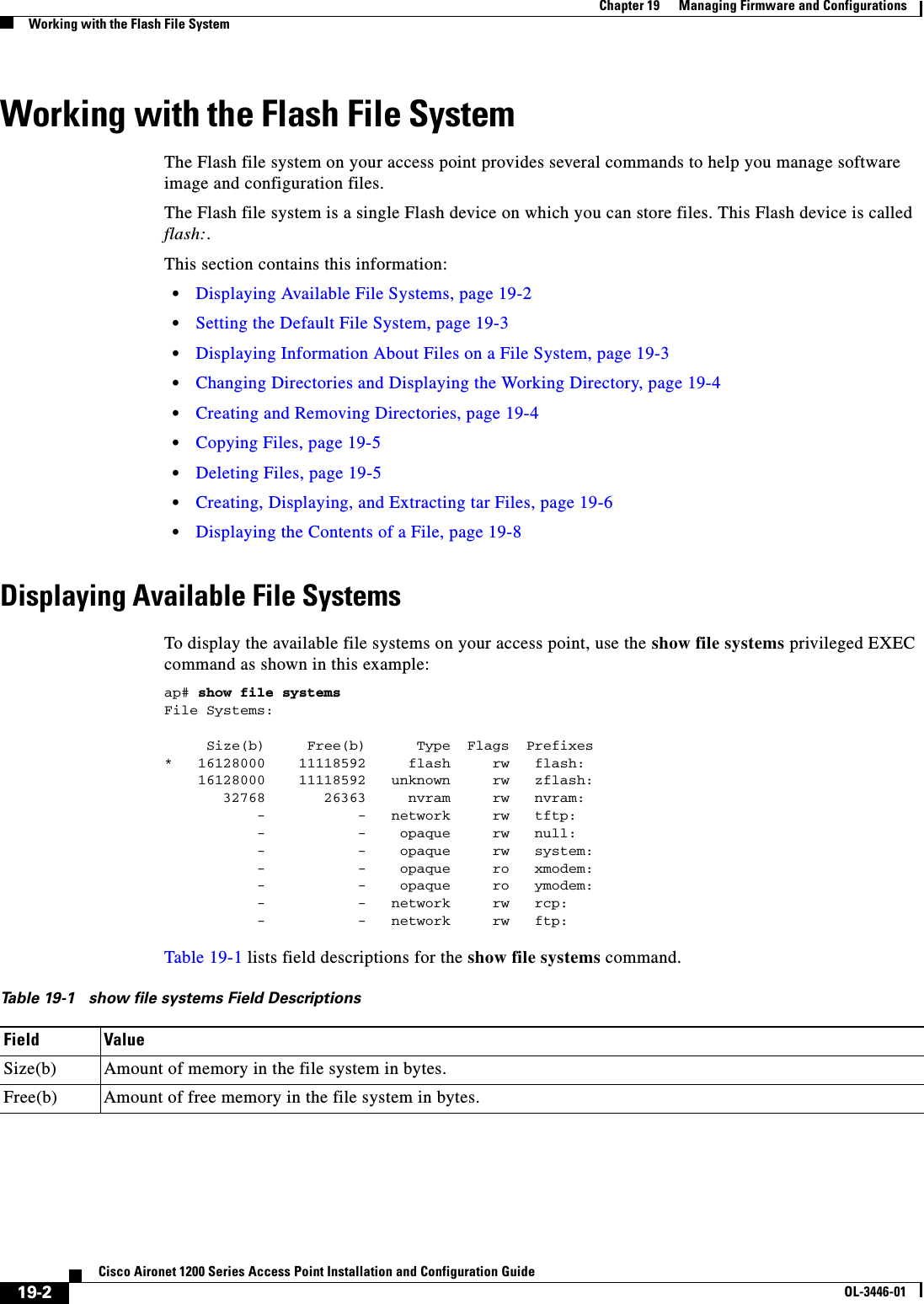
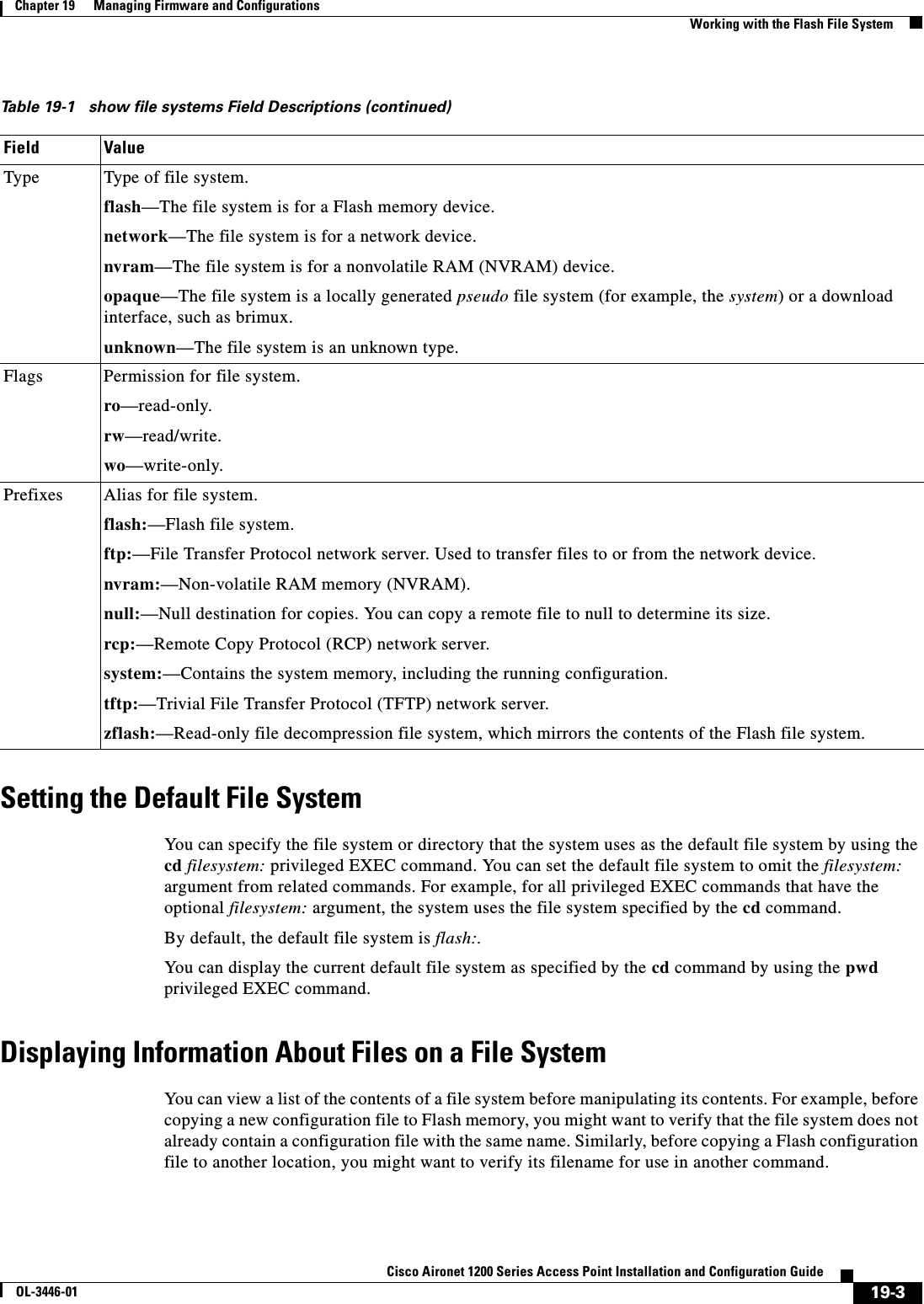
![19-4Cisco Aironet 1200 Series Access Point Installation and Configuration GuideOL-3446-01Chapter 19 Managing Firmware and ConfigurationsWorking with the Flash File SystemTo display information about files on a file system, use one of the privileged EXEC commands in Table 19-2:Changing Directories and Displaying the Working DirectoryBeginning in privileged EXEC mode, follow these steps to change directories and display the working directory.Creating and Removing DirectoriesBeginning in privileged EXEC mode, follow these steps to create and remove a directory:To delete a directory with all its files and subdirectories, use the delete /force /recursive filesystem:/file-url privileged EXEC command. Table 19-2 Commands for Displaying Information About FilesCommand Descriptiondir [/all] [filesystem:][filename] Display a list of files on a file system.show file systems Display more information about each of the files on a file system.show file information file-url Display information about a specific file.show file descriptors Display a list of open file descriptors. File descriptors are the internal representations of open files. You can use this command to see if another user has a file open.Command PurposeStep 1 dir filesystem:Display the directories on the specified file system.For filesystem:, use flash: for the system board Flash device.Step 2 cd new_configs Change to the directory of interest.The command example shows how to change to the directory named new_configs.Step 3 pwd Display the working directory.Command PurposeStep 1 dir filesystem:Display the directories on the specified file system.For filesystem:, use flash: for the system board Flash device.Step 2 mkdir old_configs Create a new directory.The command example shows how to create the directory named old_configs.Directory names are case sensitive. Directory names are limited to 45 characters between the slashes (/); the name cannot contain control characters, spaces, deletes, slashes, quotes, semicolons, or colons.Step 3 dir filesystem:Verify your entry.](https://usermanual.wiki/Cisco-Systems/102053.CRN-27004-Question-6-AP-user-manual/User-Guide-441628-Page-236.png)
![19-5Cisco Aironet 1200 Series Access Point Installation and Configuration GuideOL-3446-01Chapter 19 Managing Firmware and ConfigurationsWorking with the Flash File SystemUse the /recursive keyword to delete the named directory and all subdirectories and the files contained in it. Use the /force keyword to suppress the prompting that confirms a deletion of each file in the directory. You are prompted only once at the beginning of this deletion process. Use the /force and /recursive keywords for deleting old software images that were installed by using the archive download-sw command but are no longer needed.For filesystem, use flash: for the system board Flash device. For file-url, enter the name of the directory to be deleted. All the files in the directory and the directory are removed.Caution When files and directories are deleted, their contents cannot be recovered.Copying FilesTo copy a file from a source to a destination, use the copy [/erase]source-url destination-url privileged EXEC command. For the source and destination URLs, you can use running-config and startup-configkeyword shortcuts. For example, the copy running-config startup-config command saves the currently running configuration file to the NVRAM section of Flash memory to be used as the configuration during system initialization.Network file system URLs include ftp:,rcp:, and tftp: and have the following syntax:•File Transfer Protocol (FTP)—ftp:[[//username [:password]@location]/directory]/filename•Remote Copy Protocol (RCP)—rcp:[[//username@location]/directory]/filename•Trivial File Transfer Protocol (TFTP)—tftp:[[//location]/directory]/filenameLocal writable file systems include flash:.Some invalid combinations of source and destination exist. Specifically, you cannot copy these combinations:•From a running configuration to a running configuration•From a startup configuration to a startup configuration•From a device to the same device (for example, the copy flash: flash: command is invalid)For specific examples of using the copy command with configuration files, see the “Working with Configuration Files” section on page 19-8.To copy software images either by downloading a new version or uploading the existing one, use the archive download-sw or the archive upload-sw privileged EXEC command. For more information, see the “Working with Software Images” section on page 19-18.Deleting FilesWhen you no longer need a file on a Flash memory device, you can permanently delete it. To delete a file or directory from a specified Flash device, use the delete [/force] [/recursive] [filesystem:]/file-urlprivileged EXEC command. Caution When files are deleted, their contents cannot be recovered.](https://usermanual.wiki/Cisco-Systems/102053.CRN-27004-Question-6-AP-user-manual/User-Guide-441628-Page-237.png)
![19-6Cisco Aironet 1200 Series Access Point Installation and Configuration GuideOL-3446-01Chapter 19 Managing Firmware and ConfigurationsWorking with the Flash File SystemUse the /recursive keyword for deleting a directory and all subdirectories and the files contained in it. Use the /force keyword to suppress the prompting that confirms a deletion of each file in the directory. You are prompted only once at the beginning of this deletion process. Use the /force and /recursivekeywords for deleting old software images that were installed by using the archive download-swcommand but are no longer needed.If you omit the filesystem: option, the access point uses the default device specified by the cd command. For file-url, you specify the path (directory) and the name of the file to be deleted.This example shows how to delete the file myconfig from the default Flash memory device:ap# delete myconfigCreating, Displaying, and Extracting tar FilesYou can create a tar file and write files into it, list the files in a tar file, and extract the files from a tar file as described in the next sections.Creating a tar FileTo create a tar file and write files into it, use this privileged EXEC command:archive tar /create destination-url flash:/file-urlFor destination-url, specify the destination URL alias for the local or network file system and the name of the tar file to create. These options are supported:•For the local Flash file system, the syntax isflash:/file-url•For the File Transfer Protocol (FTP), the syntax is ftp:[[//username[:password]@location]/directory]/tar-filename.tar•For the Remote Copy Protocol (RCP), the syntax is rcp:[[//username@location]/directory]/tar-filename.tar•For the Trivial File Transfer Protocol (TFTP), the syntax is tftp:[[//location]/directory]/tar-filename.tarThe tar-filename.tar is the tar file to be created.For flash:/file-url, specify the location on the local Flash file system from which the new tar file is created. You can also specify an optional list of files or directories within the source directory to write to the new tar file. If none are specified, all files and directories at this level are written to the newly created tar file.This example shows how to create a tar file. This command writes the contents of the new-configsdirectory on the local Flash device to a file named saved.tar on the TFTP server at 172.20.10.30:ap# archive tar /create tftp:172.20.10.30/saved.tar flash:/new-configsDisplaying the Contents of a tar FileTo display the contents of a tar file on the screen, use this privileged EXEC command:archive tar /table source-url](https://usermanual.wiki/Cisco-Systems/102053.CRN-27004-Question-6-AP-user-manual/User-Guide-441628-Page-238.png)
![19-7Cisco Aironet 1200 Series Access Point Installation and Configuration GuideOL-3446-01Chapter 19 Managing Firmware and ConfigurationsWorking with the Flash File SystemFor source-url, specify the source URL alias for the local or network file system. These options are supported:•For the local Flash file system, the syntax isflash:•For the File Transfer Protocol (FTP), the syntax is ftp:[[//username[:password]@location]/directory]/tar-filename.tar•For the Remote Copy Protocol (RCP), the syntax is rcp:[[//username@location]/directory]/tar-filename.tar•For the Trivial File Transfer Protocol (TFTP), the syntax is tftp:[[//location]/directory]/tar-filename.tarThe tar-filename.tar is the tar file to display.You can also limit the display of the files by specifying an optional list of files or directories after the tar file; then only these files are displayed. If none are specified, all files and directories are displayed.This example shows how to display the contents of the c1200-k9w7-mx.122-8.JA.tar file that is in Flash memory:ap# archive tar /table flash:c1200-k9w7-mx.122-8.JA.tarinfo (219 bytes)c1200-k9w7-mx.122-8.JA/ (directory)c1200-k9w7-mx.122-8.JA/html/ (directory)c1200-k9w7-mx.122-8.JA/html/foo.html (0 bytes)c1200-k9w7-mx.122-8.JA/c1200-k9w7-mx.122-8.JA.bin (610856 bytes)c1200-k9w7-mx.122-8.JA/info (219 bytes)info.ver (219 bytes)This example shows how to display only the c1200-k9w7-mx.122-8.JA/html directory and its contents:ap# archive tar /table flash:c1200-k9w7-mx.122-8.JA/htmlc1200-k9w7-mx.122-8.JA/html/ (directory)c1200-k9w7-mx.122-8.JA/html/foo.html (0 bytes)Extracting a tar FileTo extract a tar file into a directory on the Flash file system, use this privileged EXEC command:archive tar /xtract source-url flash:/file-urlFor source-url, specify the source URL alias for the local or network file system. These options are supported:•For the local Flash file system, the syntax isflash:•For the File Transfer Protocol (FTP), the syntax is ftp:[[//username[:password]@location]/directory]/tar-filename.tar•For the Remote Copy Protocol (RCP), the syntax is rcp:[[//username@location]/directory]/tar-filename.tar•For the Trivial File Transfer Protocol (TFTP), the syntax is tftp:[[//location]/directory]/tar-filename.tarThe tar-filename.tar is the tar file from which to extract files.For flash:/file-url, specify the location on the local Flash file system into which the tar file is extracted. You can also specify an optional list of files or directories within the tar file for extraction. If none are specified, all files and directories are extracted.](https://usermanual.wiki/Cisco-Systems/102053.CRN-27004-Question-6-AP-user-manual/User-Guide-441628-Page-239.png)
![19-8Cisco Aironet 1200 Series Access Point Installation and Configuration GuideOL-3446-01Chapter 19 Managing Firmware and ConfigurationsWorking with Configuration FilesThis example shows how to extract the contents of a tar file located on the TFTP server at 172.20.10.30. This command extracts just the new-configs directory into the root directory on the local Flash file system. The remaining files in the saved.tar file are ignored.ap# archive tar /xtract tftp://172.20.10.30/saved.tar flash:/new-configsDisplaying the Contents of a FileTo display the contents of any readable file, including a file on a remote file system, use the more [/ascii|/binary | /ebcdic]file-url privileged EXEC command: This example shows how to display the contents of a configuration file on a TFTP server:ap# more tftp://serverA/hampton/savedconfig!! Saved configuration on server!version 11.3service timestamps log datetime localtimeservice linenumberservice udp-small-serversservice pt-vty-logging!<output truncated>Working with Configuration FilesThis section describes how to create, load, and maintain configuration files. Configuration files contain commands entered to customize the function of the Cisco IOS software. To better benefit from these instructions, your access point contains a minimal default running configuration for interacting with the system software. You can copy (download) configuration files from a TFTP, FTP, or RCP server to the running configuration of the access point for various reasons:•To restore a backed-up configuration file.•To use the configuration file for another access point. For example, you might add another access point to your network and want it to have a configuration similar to the original access point. By copying the file to the new access point, you can change the relevant parts rather than recreating the whole file.•To load the same configuration commands on all the access points in your network so that all the access points have similar configurations.You can co py (upload) configuration files from the access point to a file server by using TFTP, FTP, or RCP. You might perform this task to back up a current configuration file to a server before changing its contents so that you can later restore the original configuration file from the server. The protocol you use depends on which type of server you are using. The FTP and RCP transport mechanisms provide faster performance and more reliable delivery of data than TFTP. These improvements are possible because FTP and RCP are built on and use the Transmission Control Protocol/Internet Protocol (TCP/IP) stack, which is connection oriented.](https://usermanual.wiki/Cisco-Systems/102053.CRN-27004-Question-6-AP-user-manual/User-Guide-441628-Page-240.png)
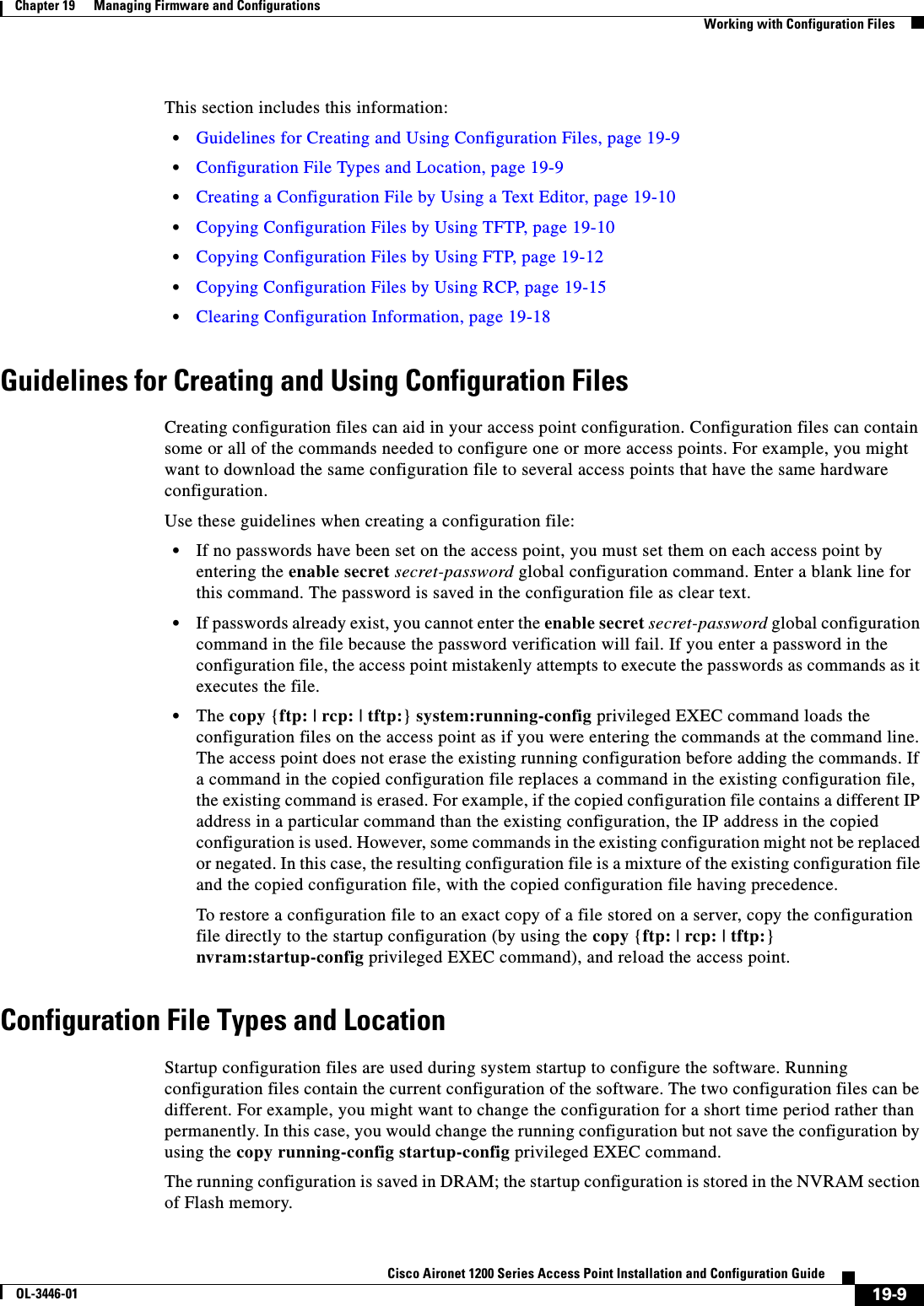
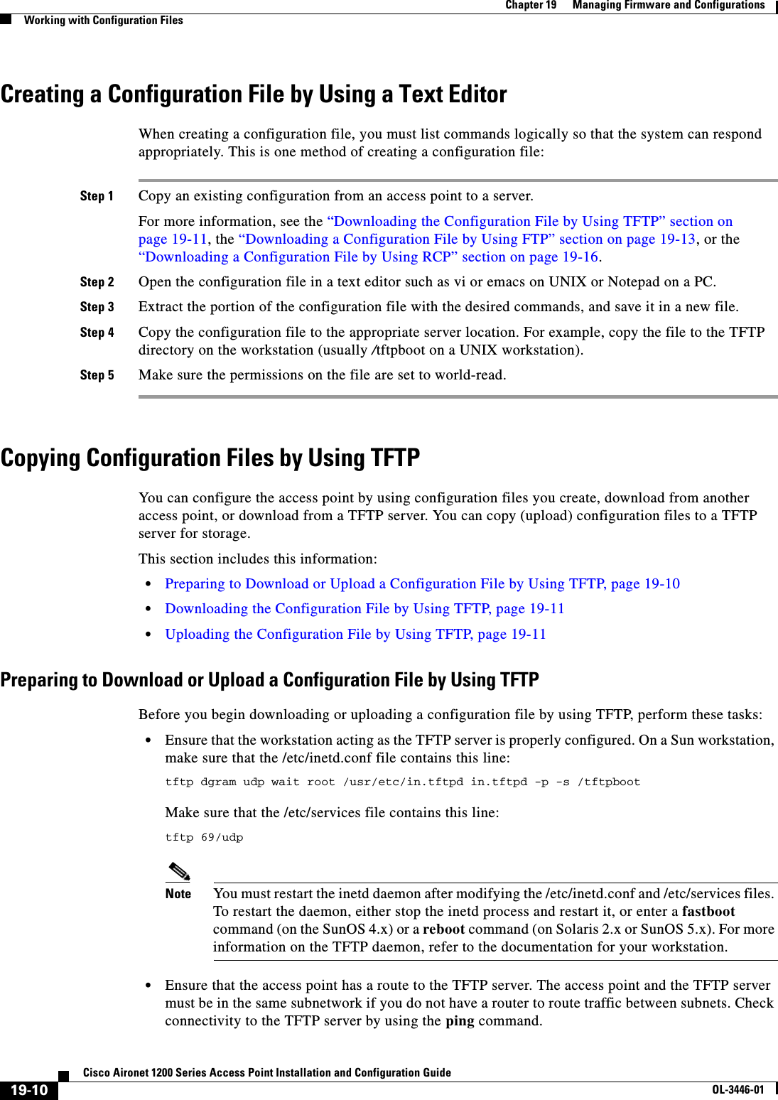
![19-11Cisco Aironet 1200 Series Access Point Installation and Configuration GuideOL-3446-01Chapter 19 Managing Firmware and ConfigurationsWorking with Configuration Files•Ensure that the configuration file to be downloaded is in the correct directory on the TFTP server (usually /tftpboot on a UNIX workstation).•For download operations, ensure that the permissions on the file are set correctly. The permission on the file should be world-read.•Before uploading the configuration file, you might need to create an empty file on the TFTP server. To create an empty file, enter the touch filename command, where filename is the name of the file you will use when uploading it to the server.•During upload operations, if you are overwriting an existing file (including an empty file, if you had to create one) on the server, ensure that the permissions on the file are set correctly. Permissions on the file should be world-write.Downloading the Configuration File by Using TFTPTo configure the access point by using a configuration file downloaded from a TFTP server, follow these steps:Step 1 Copy the configuration file to the appropriate TFTP directory on the workstation.Step 2 Verify that the TFTP server is properly configured by referring to the “Preparing to Download or Upload a Configuration File by Using TFTP” section on page 19-10.Step 3 Log into the access point through a Telnet session.Step 4 Download the configuration file from the TFTP server to configure the access point. Specify the IP address or host name of the TFTP server and the name of the file to download.Use one of these privileged EXEC commands:•copy tftp:[[[//location]/directory]/filename]system:running-config•copy tftp:[[[//location]/directory]/filename]nvram:startup-configThe configuration file downloads, and the commands are executed as the file is parsed line-by-line.This example shows how to configure the software from the file tokyo-confg at IP address 172.16.2.155:ap# copy tftp://172.16.2.155/tokyo-confg system:running-configConfigure using tokyo-confg from 172.16.2.155? [confirm] yBooting tokyo-confg from 172.16.2.155:!!! [OK - 874/16000 bytes]Uploading the Configuration File by Using TFTPTo upload a configuration file from an access point to a TFTP server for storage, follow these steps:Step 1 Verify that the TFTP server is properly configured by referring to the “Preparing to Download or Upload a Configuration File by Using TFTP” section on page 19-10.Step 2 Log into the access point through a Telnet session.Step 3 Upload the access point configuration to the TFTP server. Specify the IP address or host name of the TFTP server and the destination filename.](https://usermanual.wiki/Cisco-Systems/102053.CRN-27004-Question-6-AP-user-manual/User-Guide-441628-Page-243.png)
![19-12Cisco Aironet 1200 Series Access Point Installation and Configuration GuideOL-3446-01Chapter 19 Managing Firmware and ConfigurationsWorking with Configuration FilesUse one of these privileged EXEC commands:•copy system:running-config tftp:[[[//location]/directory]/filename]•copy nvram:startup-config tftp:[[[//location]/directory]/filename]The file is uploaded to the TFTP server.This example shows how to upload a configuration file from an access point to a TFTP server:ap# copy system:running-config tftp://172.16.2.155/tokyo-confgWrite file tokyo-confg on host 172.16.2.155? [confirm] y#Writing tokyo-confg!!! [OK]Copying Configuration Files by Using FTPYou can copy configuration files to or from an FTP server.The FTP protocol requires a client to send a remote username and password on each FTP request to a server. When you copy a configuration file from the access point to a server by using FTP, the Cisco IOS software sends the first valid username in this list:•The username specified in the copy command if a username is specified.•The username set by the ip ftp username username global configuration command if the command is configured.•Anonymous.The access point sends the first valid password in this list:•The password specified in the copy command if a password is specified.•The password set by the ip ftp password password global configuration command if the command is configured.•The access point forms a password named username@apname.domain. The variable username is the username associated with the current session, apname is the configured host name, and domain is the domain of the access point.The username and password must be associated with an account on the FTP server. If you are writing to the server, the FTP server must be properly configured to accept your FTP write request.Use the ip ftp username and ip ftp password commands to specify a username and password for all copies. Include the username in the copy command if you want to specify only a username for that copy operation. If the server has a directory structure, the configuration file is written to or copied from the directory associated with the username on the server. For example, if the configuration file resides in the home directory of a user on the server, specify that user's name as the remote username. For more information, refer to the documentation for your FTP server.This section includes this information:•Preparing to Download or Upload a Configuration File by Using FTP, page 19-13•Downloading a Configuration File by Using FTP, page 19-13•Uploading a Configuration File by Using FTP, page 19-14](https://usermanual.wiki/Cisco-Systems/102053.CRN-27004-Question-6-AP-user-manual/User-Guide-441628-Page-244.png)
![19-13Cisco Aironet 1200 Series Access Point Installation and Configuration GuideOL-3446-01Chapter 19 Managing Firmware and ConfigurationsWorking with Configuration FilesPreparing to Download or Upload a Configuration File by Using FTPBefore you begin downloading or uploading a configuration file by using FTP, perform these tasks:•Ensure that the access point has a route to the FTP server. The access point and the FTP server must be in the same subnetwork if you do not have a router to route traffic between subnets. Check connectivity to the FTP server by using the ping command.•If you are accessing the access point through a Telnet session and you do not have a valid username, make sure that the current FTP username is the one that you want to use for the FTP download. You can enter the show users privileged EXEC command to view the valid username. If you do not want to use this username, create a new FTP username by using the ip ftp username username global configuration command during all copy operations. The new username is stored in NVRAM. If you are accessing the access point through a Telnet session and you have a valid username, this username is used, and you do not need to set the FTP username. Include the username in the copy command if you want to specify a username for only that copy operation. •When you upload a configuration file to the FTP server, it must be properly configured to accept the write request from the user on the access point.For more information, refer to the documentation for your FTP server.Downloading a Configuration File by Using FTPBeginning in privileged EXEC mode, follow these steps to download a configuration file by using FTP:This example shows how to copy a configuration file named host1-confg from the netadmin1 directory on the remote server with an IP address of 172.16.101.101 and to load and run those commands on the access point:ap# copy ftp://netadmin1:mypass@172.16.101.101/host1-confg system:running-configConfigure using host1-confg from 172.16.101.101? [confirm]Command PurposeStep 1 Verify that the FTP server is properly configured by referring to the “Preparing to Download or Upload a Configuration File by Using FTP” section on page 19-13.Step 2 Log into the access point through a Telnet session.Step 3 configure terminal Enter global configuration mode on the access point.This step is required only if you override the default remote username or password (see Steps 4, 5, and 6). Step 4 ip ftp username username (Optional) Change the default remote username.Step 5 ip ftp password password (Optional) Change the default password.Step 6 end Return to privileged EXEC mode. Step 7 copy ftp:[[[//[username[:password]@]location]/directory]/filename]system:running-configor copy ftp:[[[//[username[:password]@]location]/directory]/filename]nvram:startup-configUsing FTP, copy the configuration file from a network server to the running configuration or to the startup configuration file.](https://usermanual.wiki/Cisco-Systems/102053.CRN-27004-Question-6-AP-user-manual/User-Guide-441628-Page-245.png)
![19-14Cisco Aironet 1200 Series Access Point Installation and Configuration GuideOL-3446-01Chapter 19 Managing Firmware and ConfigurationsWorking with Configuration FilesConnected to 172.16.101.101Loading 1112 byte file host1-confg:![OK]ap#%SYS-5-CONFIG: Configured from host1-config by ftp from 172.16.101.101This example shows how to specify a remote username of netadmin1. The software copies the configuration file host2-confg from the netadmin1 directory on the remote server with an IP address of 172.16.101.101 to the access point startup configuration.ap# configure terminalap(config)# ip ftp username netadmin1ap(config)# ip ftp password mypassap(config)# endap# copy ftp: nvram:startup-configAddress of remote host [255.255.255.255]? 172.16.101.101Name of configuration file[rtr2-confg]? host2-confgConfigure using host2-confg from 172.16.101.101?[confirm]Connected to 172.16.101.101Loading 1112 byte file host2-confg:![OK][OK]ap#%SYS-5-CONFIG_NV:Non-volatile store configured from host2-config by ftp from 172.16.101.101Uploading a Configuration File by Using FTPBeginning in privileged EXEC mode, follow these steps to upload a configuration file by using FTP:This example shows how to copy the running configuration file named ap2-confg to the netadmin1directory on the remote host with an IP address of 172.16.101.101: ap# copy system:running-config ftp://netadmin1:mypass@172.16.101.101/ap2-confgWrite file ap2-confg on host 172.16.101.101?[confirm]Command PurposeStep 1 Verify that the FTP server is properly configured by referring to the “Preparing to Download or Upload a Configuration File by Using FTP” section on page 19-13.Step 2 Log into the access point through a Telnet session.Step 3 configure terminal Enter global configuration mode.This step is required only if you override the default remote username or password (see Steps 4, 5, and 6). Step 4 ip ftp username username (Optional) Change the default remote username.Step 5 ip ftp password password (Optional) Change the default password.Step 6 end Return to privileged EXEC mode. Step 7 copy system:running-config ftp:[[[//[username[:password]@]location]/directory]/filename]or copy nvram:startup-config ftp:[[[//[username[:password]@]location]/directory]/filename]Using FTP, store the access point running or startup configuration file to the specified location.](https://usermanual.wiki/Cisco-Systems/102053.CRN-27004-Question-6-AP-user-manual/User-Guide-441628-Page-246.png)
![19-15Cisco Aironet 1200 Series Access Point Installation and Configuration GuideOL-3446-01Chapter 19 Managing Firmware and ConfigurationsWorking with Configuration FilesBuilding configuration...[OK]Connected to 172.16.101.101ap#This example shows how to store a startup configuration file on a server by using FTP to copy the file:ap# configure terminalap(config)# ip ftp username netadmin2ap(config)# ip ftp password mypassap(config)# endap# copy nvram:startup-config ftp:Remote host[]? 172.16.101.101Name of configuration file to write [ap2-confg]?Write file ap2-confg on host 172.16.101.101?[confirm]![OK]Copying Configuration Files by Using RCPThe Remote Copy Protocol (RCP) provides another method of downloading, uploading, and copying configuration files between remote hosts and the access point. Unlike TFTP, which uses User Datagram Protocol (UDP), a connectionless protocol, RCP uses TCP, which is connection-oriented. To use RCP to copy files, the server from or to which you will be copying files must support RCP. The RCP copy commands rely on the rsh server (or daemon) on the remote system. To copy files by using RCP, you do not need to create a server for file distribution as you do with TFTP. You only need to have access to a server that supports the remote shell (rsh). (Most UNIX systems support rsh.) Because you are copying a file from one place to another, you must have read permission on the source file and write permission on the destination file. If the destination file does not exist, RCP creates it for you.The RCP requires a client to send a remote username with each RCP request to a server. When you copy a configuration file from the access point to a server, the Cisco IOS software sends the first valid username in this list:•The username specified in the copy command if a username is specified.•The username set by the ip rcmd remote-username username global configuration command if the command is configured.•The remote username associated with the current TTY (terminal) process. For example, if the user is connected to the router through Telnet and was authenticated through the username command, the access point software sends the Telnet username as the remote username. •The access point host name.For a successful RCP copy request, you must define an account on the network server for the remote username. If the server has a directory structure, the configuration file is written to or copied from the directory associated with the remote username on the server. For example, if the configuration file is in the home directory of a user on the server, specify that user's name as the remote username. This section includes this information:•Preparing to Download or Upload a Configuration File by Using RCP, page 19-16•Downloading a Configuration File by Using RCP, page 19-16•Uploading a Configuration File by Using RCP, page 19-17](https://usermanual.wiki/Cisco-Systems/102053.CRN-27004-Question-6-AP-user-manual/User-Guide-441628-Page-247.png)
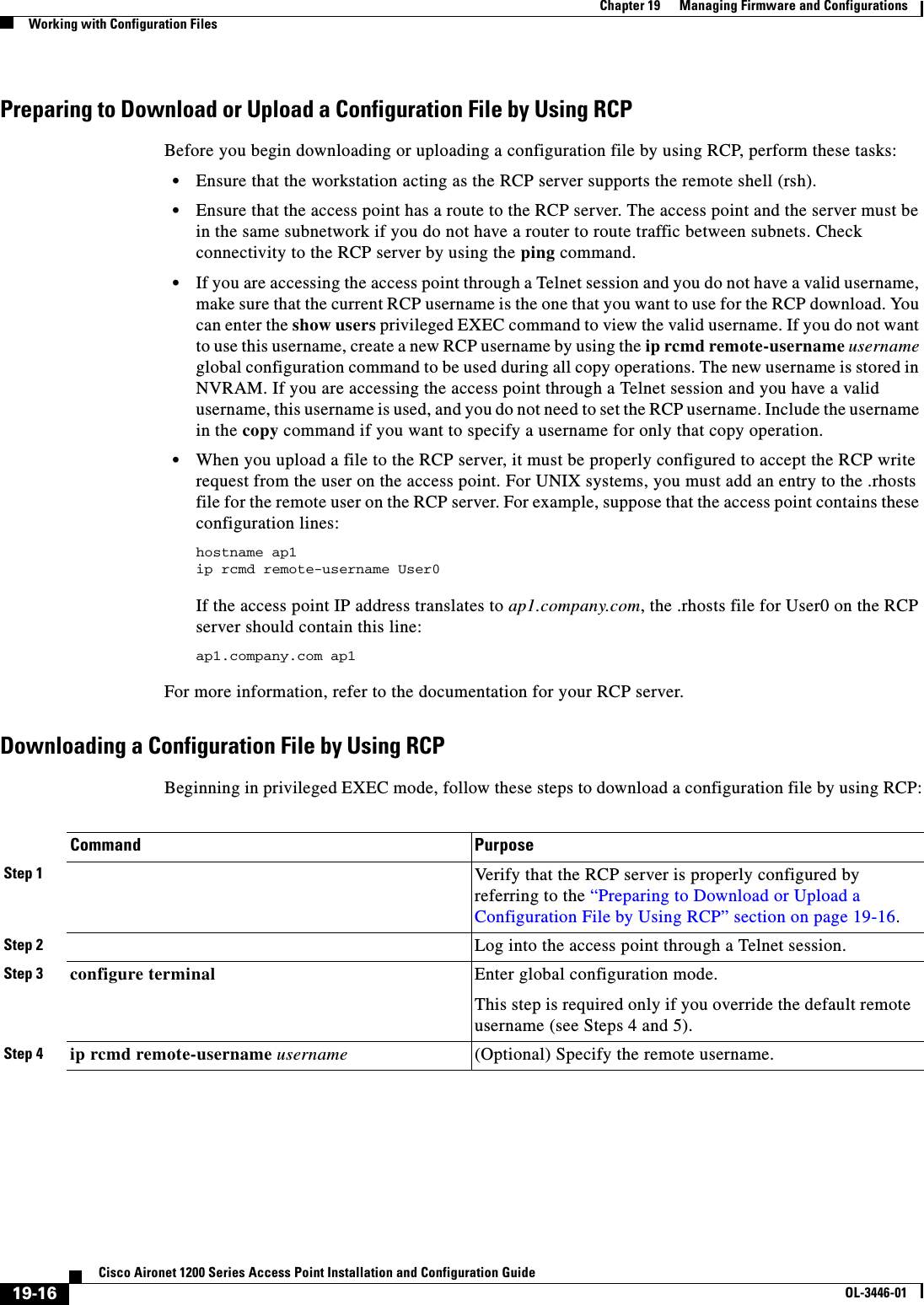
![19-17Cisco Aironet 1200 Series Access Point Installation and Configuration GuideOL-3446-01Chapter 19 Managing Firmware and ConfigurationsWorking with Configuration FilesThis example shows how to copy a configuration file named host1-confg from the netadmin1 directory on the remote server with an IP address of 172.16.101.101 and load and run those commands on the access point:ap# copy rcp://netadmin1@172.16.101.101/host1-confg system:running-configConfigure using host1-confg from 172.16.101.101? [confirm]Connected to 172.16.101.101Loading 1112 byte file host1-confg:![OK]ap#%SYS-5-CONFIG: Configured from host1-config by rcp from 172.16.101.101This example shows how to specify a remote username of netadmin1. Then it copies the configuration file host2-confg from the netadmin1 directory on the remote server with an IP address of 172.16.101.101 to the startup configuration:ap# configure terminalap(config)# ip rcmd remote-username netadmin1ap(config)# endap# copy rcp: nvram:startup-configAddress of remote host [255.255.255.255]? 172.16.101.101Name of configuration file[rtr2-confg]? host2-confgConfigure using host2-confg from 172.16.101.101?[confirm]Connected to 172.16.101.101Loading 1112 byte file host2-confg:![OK][OK]ap#%SYS-5-CONFIG_NV:Non-volatile store configured from host2-config by rcp from 172.16.101.101Uploading a Configuration File by Using RCPBeginning in privileged EXEC mode, follow these steps to upload a configuration file by using RCP:Step 5 end Return to privileged EXEC mode. Step 6 copy rcp:[[[//[username@]location]/directory]/filename]system:running-configor copy rcp:[[[//[username@]location]/directory]/filename]nvram:startup-configUsing RCP, copy the configuration file from a network server to the running configuration or to the startup configuration file. Command PurposeCommand PurposeStep 1 Verify that the RCP server is properly configured by referring to the “Preparing to Download or Upload a Configuration File by Using RCP” section on page 19-16.Step 2 Log into the access point through a Telnet session.Step 3 configure terminal Enter global configuration mode.This step is required only if you override the default remote username (see Steps 4 and 5). Step 4 ip rcmd remote-username username (Optional) Specify the remote username.](https://usermanual.wiki/Cisco-Systems/102053.CRN-27004-Question-6-AP-user-manual/User-Guide-441628-Page-249.png)
![19-18Cisco Aironet 1200 Series Access Point Installation and Configuration GuideOL-3446-01Chapter 19 Managing Firmware and ConfigurationsWorking with Software ImagesThis example shows how to copy the running configuration file named ap2-confg to the netadmin1directory on the remote host with an IP address of 172.16.101.101: ap# copy system:running-config rcp://netadmin1@172.16.101.101/ap2-confgWrite file ap-confg on host 172.16.101.101?[confirm]Building configuration...[OK]Connected to 172.16.101.101ap#This example shows how to store a startup configuration file on a server:ap# configure terminalap(config)# ip rcmd remote-username netadmin2ap(config)# endap# copy nvram:startup-config rcp:Remote host[]? 172.16.101.101Name of configuration file to write [ap2-confg]?Write file ap2-confg on host 172.16.101.101?[confirm]![OK]Clearing Configuration InformationThis section describes how to clear configuration information. Deleting a Stored Configuration FileCaution You cannot restore a file after it has been deleted. To delete a saved configuration from Flash memory, use the delete flash:filename privileged EXEC command. Depending on the setting of the file prompt global configuration command, you might be prompted for confirmation before you delete a file. By default, the access point prompts for confirmation on destructive file operations. For more information about the file prompt command, refer to the Cisco IOS Command Reference for Release 12.1.Working with Software ImagesThis section describes how to archive (download and upload) software image files, which contain the system software, IOS code, radio firmware, and the web management HTML files.You download an access point image file from a TFTP, FTP, or RCP server to upgrade the access point software. You upload an access point image file to a TFTP, FTP, or RCP server for backup purposes. You can use this uploaded image for future downloads to the same access point or another of the same type.Step 5 end Return to privileged EXEC mode. Step 6 copy system:running-config rcp:[[[//[username@]location]/directory]/filename]or copy nvram:startup-config rcp:[[[//[username@]location]/directory]/filename]Using RCP, copy the configuration file from an access point running or startup configuration file to a network server.Command Purpose](https://usermanual.wiki/Cisco-Systems/102053.CRN-27004-Question-6-AP-user-manual/User-Guide-441628-Page-250.png)
![19-21Cisco Aironet 1200 Series Access Point Installation and Configuration GuideOL-3446-01Chapter 19 Managing Firmware and ConfigurationsWorking with Software ImagesDownloading an Image File by Using TFTPYou can download a new image file and replace the current image or keep the current image. Caution For the download and upload algorithms to operate properly, do not rename image directories.Beginning in privileged EXEC mode, follow Steps 1 through 3 to download a new image from a TFTP server and overwrite the existing image. Note To avoid an unsuccessful download, use the archive download-sw /safe command, which downloads the image first and does not delete the current running version until the download succeeds.Command PurposeStep 1 . Copy the image to the appropriate TFTP directory on the workstation. Make sure the TFTP server is properly configured; see the “Preparing to Download or Upload an Image File by Using TFTP” section on page 19-20Step 2 Log into the access point through a Telnet session.Step 3 archive download-sw /overwrite /reload tftp:[[//location]/directory]/image-nameDownload the image file from the TFTP server to the access point, and overwrite the current image.•The /overwrite option overwrites the software image in Flash with the downloaded image.•The /reload option reloads the system after downloading the image unless the configuration has been changed and not saved.•For //location, specify the IP address of the TFTP server.•For /directory/image-name, specify the directory (optional) and the image to download. Directory and image names are case sensitive.Step 4 archive download-sw /leave-old-sw /reload tftp:[[//location]/directory]/image-nameDownload the image file from the TFTP server to the access point, and keep the current image.•The /leave-old-sw option keeps the old software version after a download.•The /reload option reloads the system after downloading the image unless the configuration has been changed and not saved.•For //location, specify the IP address of the TFTP server.•For /directory/image-name, specify the directory (optional) and the image to download. Directory and image names are case sensitive.](https://usermanual.wiki/Cisco-Systems/102053.CRN-27004-Question-6-AP-user-manual/User-Guide-441628-Page-253.png)
![19-22Cisco Aironet 1200 Series Access Point Installation and Configuration GuideOL-3446-01Chapter 19 Managing Firmware and ConfigurationsWorking with Software ImagesThe download algorithm verifies that the image is appropriate for the access point model and that enough DRAM is present, or it aborts the process and reports an error. If you specify the /overwrite option, the download algorithm removes the existing image on the Flash device whether or not it is the same as the new one, downloads the new image, and then reloads the software.Note If the Flash device has sufficient space to hold two images and you want to overwrite one of these images with the same version, you must specify the /overwrite option.If you specify the /leave-old-sw, the existing files are not removed. If there is not enough space to install the new image and keep the current running image, the download process stops, and an error message is displayed.The algorithm installs the downloaded image on the system board Flash device (flash:). The image is placed into a new directory named with the software version string, and the system boot path variable is updated to point to the newly installed image.If you kept the old image during the download process (you specified the /leave-old-sw keyword), you can remove it by entering the delete /force /recursive filesystem:/file-url privileged EXEC command. For filesystem, use flash: for the system board Flash device. For file-url, enter the directory name of the old image. All the files in the directory and the directory are removed.Uploading an Image File by Using TFTPYou can upload an image from the access point to a TFTP server. You can later download this image to the access point or to another access point of the same type.Caution For the download and upload algorithms to operate properly, do not rename image directories.Beginning in privileged EXEC mode, follow these steps to upload an image to a TFTP server:The archive upload-sw privileged EXEC command builds an image file on the server by uploading these files in order: info, the IOS image, the HTML files, and info.ver. After these files are uploaded, the upload algorithm creates the tar file format. Command PurposeStep 1 Make sure the TFTP server is properly configured; see the “Preparing to Download or Upload an Image File by Using TFTP”section on page 19-20.Step 1 Log into the access point through a Telnet session.Step 2 archive upload-swtftp:[[//location]/directory]/image-name.tarUpload the currently running access point image to the TFTP server. •For //location, specify the IP address of the TFTP server.•For /directory/image-name.tar, specify the directory (optional) and the name of the software image to be uploaded. Directory and image names are case sensitive. The image-name.tar is the name of the software image to be stored on the server.](https://usermanual.wiki/Cisco-Systems/102053.CRN-27004-Question-6-AP-user-manual/User-Guide-441628-Page-254.png)
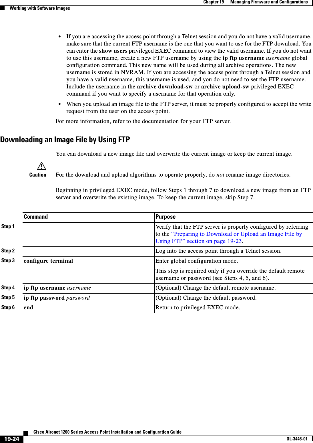
![19-25Cisco Aironet 1200 Series Access Point Installation and Configuration GuideOL-3446-01Chapter 19 Managing Firmware and ConfigurationsWorking with Software ImagesNote To avoid an unsuccessful download, use the archive download-sw /safe command, which downloads the image first and does not delete the current running version until the download succeeds.The download algorithm verifies that the image is appropriate for the access point model and that enough DRAM is present, or it aborts the process and reports an error. If you specify the /overwrite option, the download algorithm removes the existing image on the Flash device, whether or not it is the same as the new one, downloads the new image, and then reloads the software.Note If the Flash device has sufficient space to hold two images and you want to overwrite one of these images with the same version, you must specify the /overwrite option.Step 7 archive download-sw /overwrite /reload ftp:[[//username[:password]@location]/directory]/image-name.tarDownload the image file from the FTP server to the access point, and overwrite the current image.•The /overwrite option overwrites the software image in Flash with the downloaded image.•The /reload option reloads the system after downloading the image unless the configuration has been changed and not saved.•For //username[:password], specify the username and password; these must be associated with an account on the FTP server. For more information, see the “Preparing to Download or Upload an Image File by Using FTP” section on page 19-23.•For @location, specify the IP address of the FTP server.•For directory/image-name.tar, specify the directory (optional) and the image to download. Directory and image names are case sensitive.Step 8 archive download-sw /leave-old-sw /reload ftp:[[//username[:password]@location]/directory]/image-name.tarDownload the image file from the FTP server to the access point, and keep the current image.•The /leave-old-sw option keeps the old software version after a download.•The /reload option reloads the system after downloading the image unless the configuration has been changed and not saved.•For //username[:password], specify the username and password. These must be associated with an account on the FTP server. For more information, see the “Preparing to Download or Upload an Image File by Using FTP”section on page 19-23.•For @location, specify the IP address of the FTP server.•For directory/image-name.tar, specify the directory (optional) and the image to download. Directory and image names are case sensitive.Command Purpose](https://usermanual.wiki/Cisco-Systems/102053.CRN-27004-Question-6-AP-user-manual/User-Guide-441628-Page-257.png)
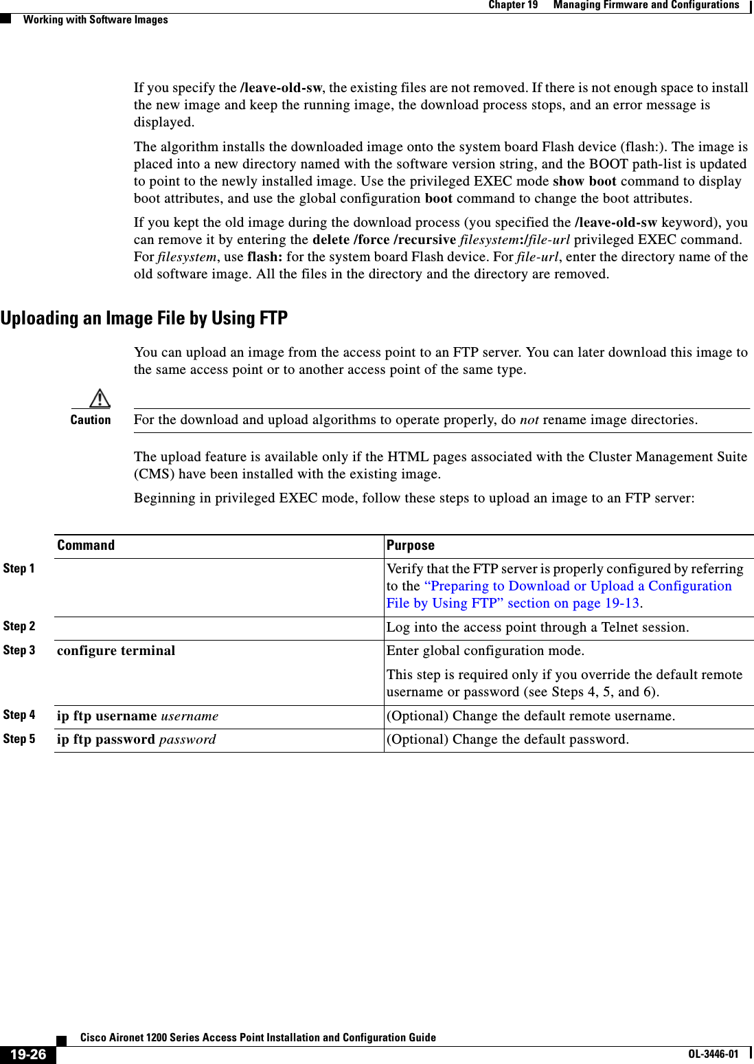
![19-27Cisco Aironet 1200 Series Access Point Installation and Configuration GuideOL-3446-01Chapter 19 Managing Firmware and ConfigurationsWorking with Software ImagesThe archive upload-sw command builds an image file on the server by uploading these files in order: info, the IOS image, the HTML files, and info.ver. After these files are uploaded, the upload algorithm creates the tar file format. Copying Image Files by Using RCPYou can download an access point image from an RCP server or upload the image from the access point to an RCP server.You download an access point image file from a server to upgrade the access point software. You can overwrite the current image with the new one or keep the current image after a download.You upload an access point image file to a server for backup purposes. You can use this uploaded image for future downloads to the same access point or another of the same type.This section includes this information:•Preparing to Download or Upload an Image File by Using RCP, page 19-27•Downloading an Image File by Using RCP, page 19-29•Uploading an Image File by Using RCP, page 19-31Preparing to Download or Upload an Image File by Using RCPRCP provides another method of downloading and uploading image files between remote hosts and the access point. Unlike TFTP, which uses User Datagram Protocol (UDP), a connectionless protocol, RCP uses TCP, which is connection-oriented. To use RCP to copy files, the server from or to which you will be copying files must support RCP. The RCP copy commands rely on the rsh server (or daemon) on the remote system. To copy files by using RCP, you do not need to create a server for file distribution as you do with TFTP. You only need to have access to a server that supports the remote shell (rsh). (Most UNIX systems support rsh.) Because you are copying a file from one place to another, you must have read permission on the source file and write permission on the destination file. If the destination file does not exist, RCP creates it for you.Step 6 end Return to privileged EXEC mode. Step 7 archive upload-sw ftp:[[//[username[:password]@]location]/directory]/image-name.tarUpload the currently running access point image to the FTP server. •For //username:password, specify the username and password. These must be associated with an account on the FTP server. For more information, see the “Preparing to Download or Upload an Image File by Using FTP”section on page 19-23.•For @location, specify the IP address of the FTP server.•For /directory/image-name.tar, specify the directory (optional) and the name of the software image to be uploaded. Directory and image names are case sensitive. The image-name.tar is the name of the software image to be stored on the server.Command Purpose](https://usermanual.wiki/Cisco-Systems/102053.CRN-27004-Question-6-AP-user-manual/User-Guide-441628-Page-259.png)
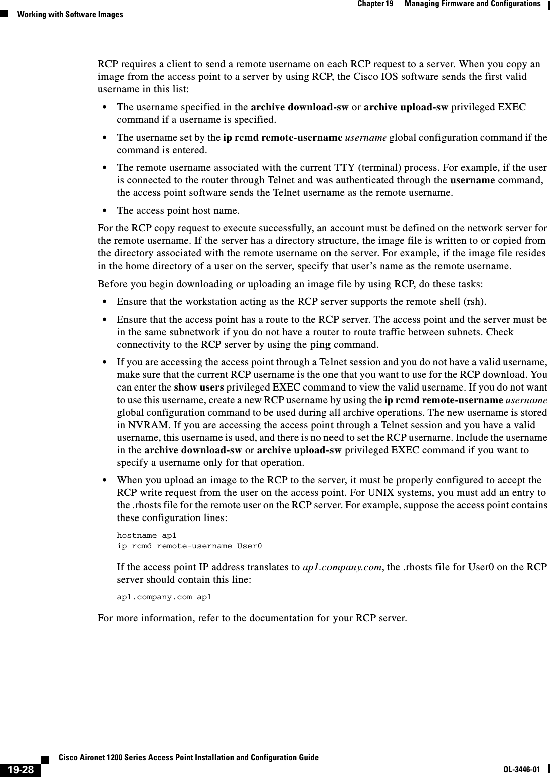
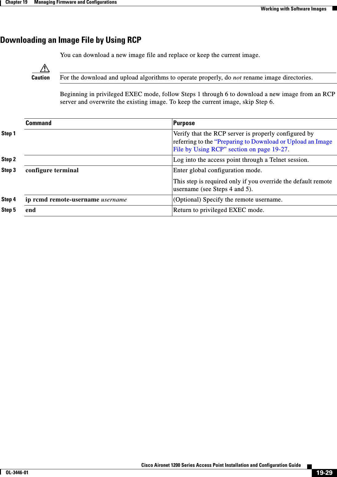
![19-30Cisco Aironet 1200 Series Access Point Installation and Configuration GuideOL-3446-01Chapter 19 Managing Firmware and ConfigurationsWorking with Software ImagesNote To avoid an unsuccessful download, use the archive download-sw /safe command, which downloads the image first and does not delete the current running version until the download succeeds.The download algorithm verifies that the image is appropriate for the access point model and that enough DRAM is present, or it aborts the process and reports an error. If you specify the /overwrite option, the download algorithm removes the existing image on the Flash device whether or not it is the same as the new one, downloads the new image, and then reloads the software.Step 6 archive download-sw /overwrite /reload rcp:[[[//[username@]location]/directory]/image-name.tar]Download the image file from the RCP server to the access point, and overwrite the current image.•The /overwrite option overwrites the software image in Flash with the downloaded image.•The /reload option reloads the system after downloading the image unless the configuration has been changed and not saved.•For //username, specify the username. For the RCP copy request to execute successfully, an account must be defined on the network server for the remote username. For more information, see the “Preparing to Download or Upload an Image File by Using RCP” section on page 19-27.•For @location, specify the IP address of the RCP server.•For /directory/image-name.tar, specify the directory (optional) and the image to download. Directory and image names are case sensitive.Step 7 archive download-sw /leave-old-sw /reload rcp:[[[//[username@]location]/directory]/image-name.tar]Download the image file from the RCP server to the access point, and keep the current image.•The /leave-old-sw option keeps the old software version after a download.•The /reload option reloads the system after downloading the image unless the configuration has been changed and not saved.•For //username, specify the username. For the RCP copy request to execute, an account must be defined on the network server for the remote username. For more information, see the “Preparing to Download or Upload an Image File by Using RCP” section on page 19-27.•For @location, specify the IP address of the RCP server.•For /directory]/image-name.tar, specify the directory (optional) and the image to download. Directory and image names are case sensitive.Command Purpose](https://usermanual.wiki/Cisco-Systems/102053.CRN-27004-Question-6-AP-user-manual/User-Guide-441628-Page-262.png)
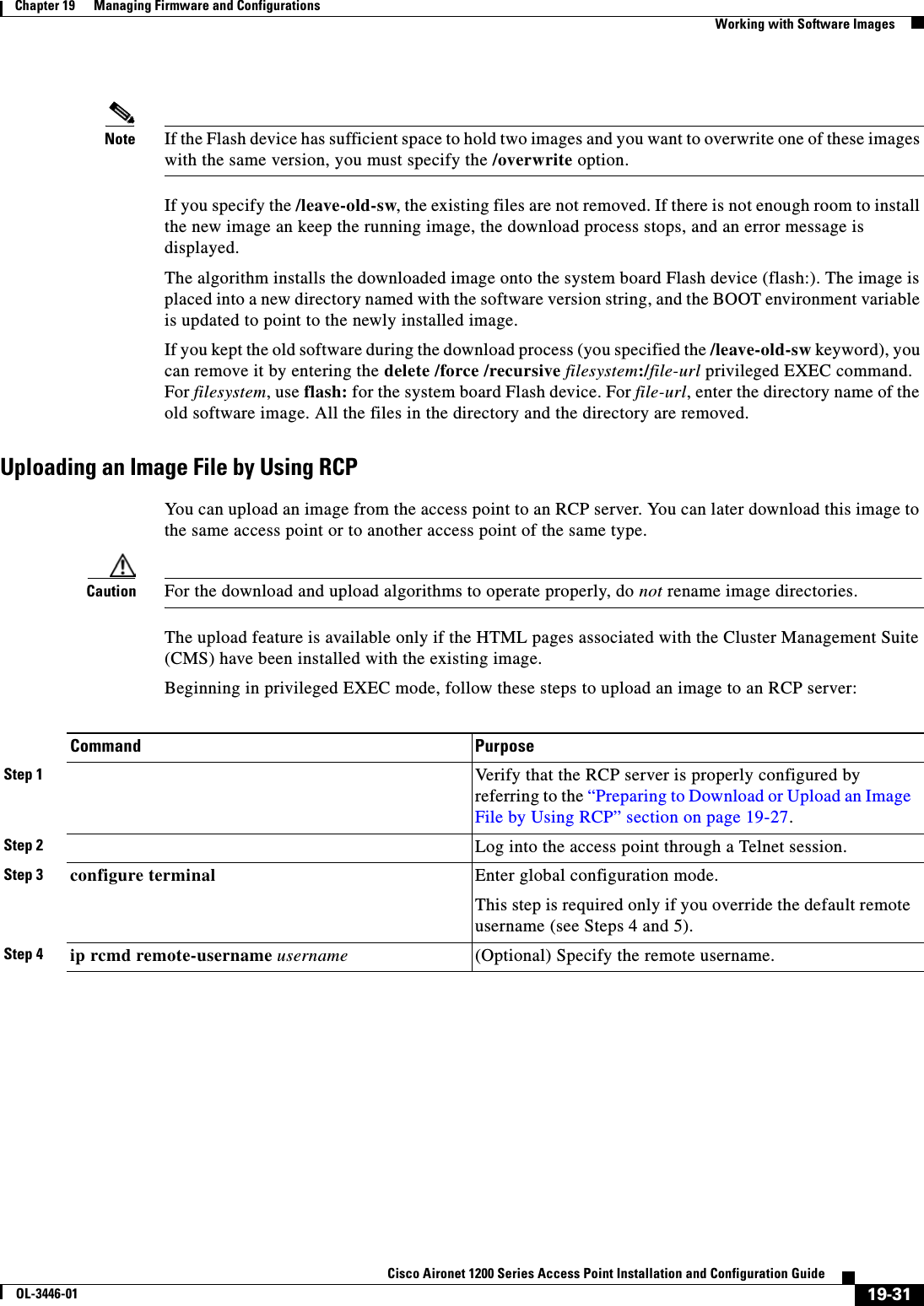
![19-32Cisco Aironet 1200 Series Access Point Installation and Configuration GuideOL-3446-01Chapter 19 Managing Firmware and ConfigurationsWorking with Software ImagesThe archive upload-sw privileged EXEC command builds an image file on the server by uploading these files in order: info, the IOS image, the HTML files, and info.ver. After these files are uploaded, the upload algorithm creates the tar file format. Reloading the Image Using the Web Browser InterfaceYou can also use the Web browser interface to reload the access point image file. The Web broswer interface supports loading the image file using HTTP or TFTP interfaces. Note Your access point configuration is not changed when using the browser to reload the image file.Browser HTTP InterfaceThe HTTP interface allows you to browse to the access point image file on your PC and download the image to the access point. Follow the instructions below to use the HTTP interface:Step 1 Open your Internet browser. You must use Microsoft Internet Explorer (version 5.x or later) or Netscape Navigator (version 4.x).Step 2 Enter the access point’s IP address in the browser address line and press Enter. An Enter Network Password screen appears.Step 3 Enter your username in the User Name field.Step 4 Enter the access point password in the Password field and press Enter. The Summary Status page appears.Step 5 Click the System Software tab and then click Software Upgrade. The HTTP Upgrade screen appears.Step 6 Click the Browse button to locate the image file on your PC.Step 5 end Return to privileged EXEC mode. Step 6 archive upload-sw rcp:[[[//[username@]location]/directory]/image-name.tar]Upload the currently running access point image to the RCP server. •For //username, specify the username; for the RCP copy request to execute, an account must be defined on the network server for the remote username. For more information, see the “Preparing to Download or Upload an Image File by Using RCP” section on page 19-27.•For @location, specify the IP address of the RCP server.•For /directory]/image-name.tar, specify the directory (optional) and the name of the software image to be uploaded. Directory and image names are case sensitive.•The image-name.tar is the name of software image to be stored on the server.Command Purpose](https://usermanual.wiki/Cisco-Systems/102053.CRN-27004-Question-6-AP-user-manual/User-Guide-441628-Page-264.png)
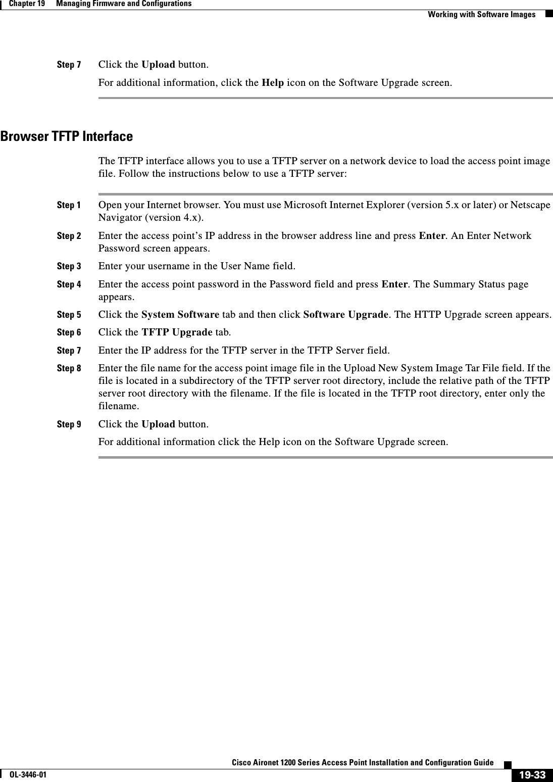

![20-2Cisco Aironet 1200 Series Access Point Installation and Configuration GuideOL-3446-01Chapter 20 Configuring System Message LoggingUnderstanding System Message LoggingUnderstanding System Message LoggingBy default, access points send the output from system messages and debug privileged EXEC commands to a logging process. The logging process controls the distribution of logging messages to various destinations, such as the logging buffer, terminal lines, or a UNIX syslog server, depending on your configuration. The process also sends messages to the console. Note The syslog format is compatible with 4.3 BSD UNIX.When the logging process is disabled, messages are sent only to the console. The messages are sent as they are generated, so message and debug output are interspersed with prompts or output from other commands. Messages are displayed on the console after the process that generated them has finished.You can set the severity level of the messages to control the type of messages displayed on the console and each of the destinations. You can timestamp log messages or set the syslog source address to enhance real-time debugging and management.You can access logged system messages by using the access point command-line interface (CLI) or by saving them to a properly configured syslog server. The access point software saves syslog messages in an internal buffer. You can remotely monitor system messages by accessing the access point through Telnet or by viewing the logs on a syslog server.Configuring System Message LoggingThis section describes how to configure system message logging. It contains this configuration information:•System Log Message Format, page 20-2•Default System Message Logging Configuration, page 20-3•Disabling and Enabling Message Logging, page 20-4•Setting the Message Display Destination Device, page 20-5•Enabling and Disabling Timestamps on Log Messages, page 20-6•Enabling and Disabling Sequence Numbers in Log Messages, page 20-6•Defining the Message Severity Level, page 20-7•Limiting Syslog Messages Sent to the History Table and to SNMP, page 20-8•Setting a Logging Rate Limit, page 20-9•Configuring UNIX Syslog Servers, page 20-10System Log Message FormatSystem log messages can contain up to 80 characters and a percent sign (%), which follows the optional sequence number or timestamp information, if configured. Messages are displayed in this format:seq no:timestamp: %facility-severity-MNEMONIC:descriptionThe part of the message preceding the percent sign depends on the setting of the service sequence-numbers,service timestamps log datetime,service timestamps log datetime [localtime][msec] [show-timezone], or service timestamps log uptime global configuration command.](https://usermanual.wiki/Cisco-Systems/102053.CRN-27004-Question-6-AP-user-manual/User-Guide-441628-Page-268.png)
![20-3Cisco Aironet 1200 Series Access Point Installation and Configuration GuideOL-3446-01Chapter 20 Configuring System Message LoggingConfiguring System Message LoggingTable 20-1 describes the elements of syslog messages.This example shows a partial access point system message:00:00:46: %LINK-3-UPDOWN: Interface Port-channel1, changed state to up00:00:47: %LINK-3-UPDOWN: Interface GigabitEthernet0/1, changed state to up00:00:47: %LINK-3-UPDOWN: Interface GigabitEthernet0/2, changed state to up00:00:48: %LINEPROTO-5-UPDOWN: Line protocol on Interface Vlan1, changed state to down00:00:48: %LINEPROTO-5-UPDOWN: Line protocol on Interface GigabitEthernet0/1, changed state to down 2*Mar 1 18:46:11: %SYS-5-CONFIG_I: Configured from console by vty2 (10.34.195.36)18:47:02: %SYS-5-CONFIG_I: Configured from console by vty2 (10.34.195.36)*Mar 1 18:48:50.483 UTC: %SYS-5-CONFIG_I: Configured from console by vty2 (10.34.195.36) Default System Message Logging ConfigurationTable 20-2 shows the default system message logging configuration.Table 20-1 System Log Message ElementsElement Descriptionseq no: Stamps log messages with a sequence number only if the service sequence-numbers global configuration command is configured. For more information, see the “Enabling and Disabling Sequence Numbers in Log Messages”section on page 20-6.timestamp formats:mm/dd hh:mm:ssorhh:mm:ss (short uptime)ord h (long uptime)Date and time of the message or event. This information appears only if the service timestamps log [datetime | log] global configuration command is configured.For more information, see the “Enabling and Disabling Timestamps on Log Messages” section on page 20-6.facility The facility to which the message refers (for example, SNMP, SYS, and so forth). A facility can be a hardware device, a protocol, or a module of the system software. It denotes the source or the cause of the system message.severity Single-digit code from 0 to 7 that is the severity of the message. For a description of the severity levels, see Table 20-3 on page 20-8.MNEMONIC Text string that uniquely describes the message.description Text string containing detailed information about the event being reported.Table 20-2 Default System Message Logging ConfigurationFeature Default SettingSystem message logging to the console EnabledConsole severity Debugging (and numerically lower levels; see Table 20-3 on page 20-8)Logging buffer size 4096 bytesLogging history size 1 message](https://usermanual.wiki/Cisco-Systems/102053.CRN-27004-Question-6-AP-user-manual/User-Guide-441628-Page-269.png)
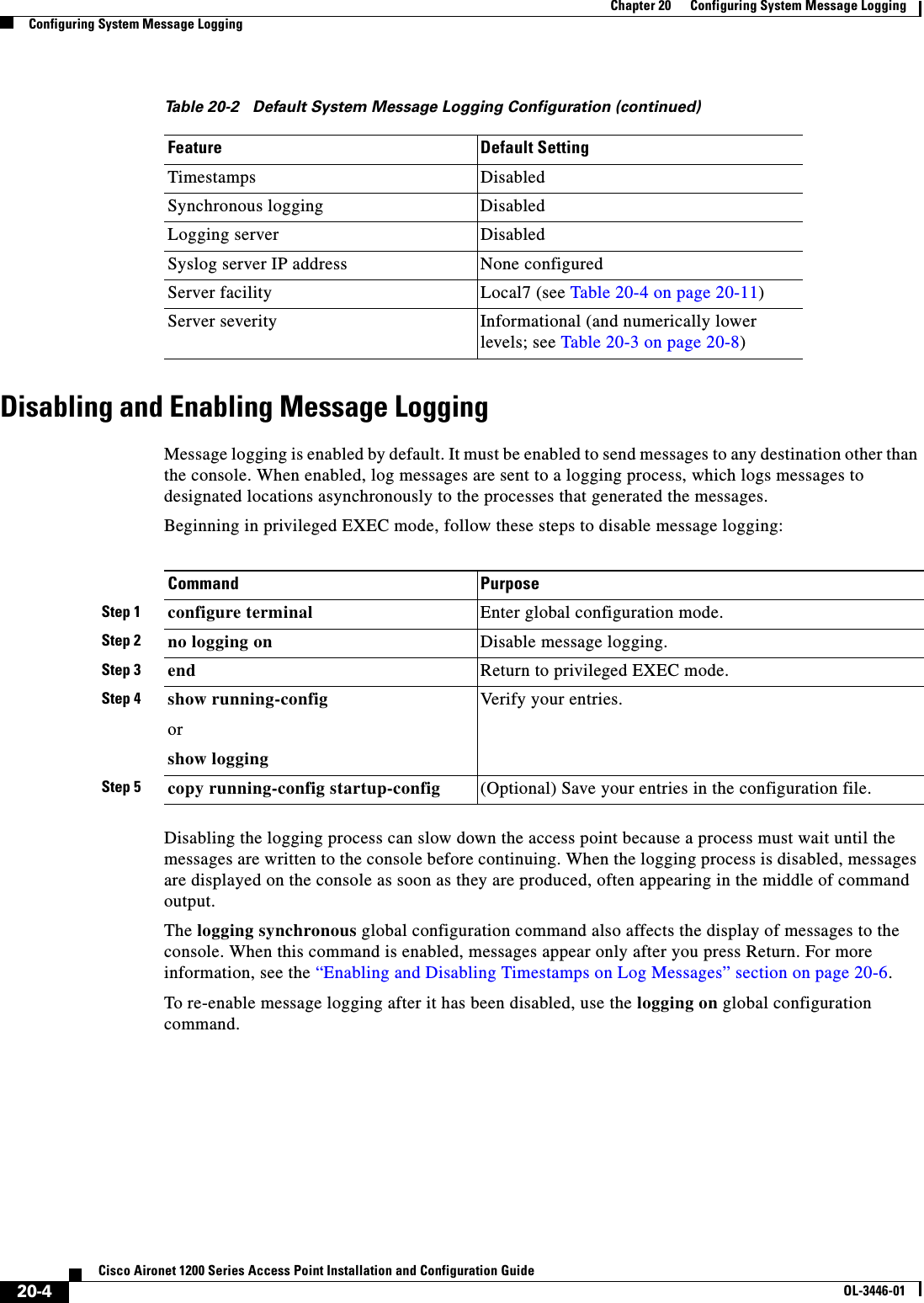
![20-5Cisco Aironet 1200 Series Access Point Installation and Configuration GuideOL-3446-01Chapter 20 Configuring System Message LoggingConfiguring System Message LoggingSetting the Message Display Destination DeviceIf message logging is enabled, you can send messages to specific locations in addition to the console. Beginning in privileged EXEC mode, use one or more of the following commands to specify the locations that receive messages:The logging buffered global configuration command copies logging messages to an internal buffer. The buffer is circular, so newer messages overwrite older messages after the buffer is full. To display the messages that are logged in the buffer, use the show logging privileged EXEC command. The first message displayed is the oldest message in the buffer. To clear the contents of the buffer, use the clear logging privileged EXEC command.To disable logging to the console, use the no logging console global configuration command. To disable logging to a file, use the no logging file [severity-level-number | type] global configuration command.Command PurposeStep 1 configure terminal Enter global configuration mode.Step 2 logging buffered [size] [level] Log messages to an internal buffer. The default buffer size is 4096. The range is 4096 to 2147483647 bytes. Levels include emergencies 0, alerts 1, critical 2, errors 3, warnings 4, notifications 5, informational 6, and debugging 7.Note Do not make the buffer size too large because the access point could run out of memory for other tasks. Use the show memoryprivileged EXEC command to view the free processor memory on the access point; however, this value is the maximum available, and you should not set the buffer size to this amount.Step 3 logging host Log messages to a UNIX syslog server host.For host, specify the name or IP address of the host to be used as the syslog server.To build a list of syslog servers that receive logging messages, enter this command more than once.For complete syslog server configuration steps, see the “Configuring UNIX Syslog Servers” section on page 20-10.Step 4 end Return to privileged EXEC mode.Step 5 terminal monitor Log messages to a non-console terminal during the current session.Terminal parameter-setting commands are set locally and do not remain in effect after the session has ended. You must perform this step for each session to see the debugging messages.Step 6 show running-config Verify your entries.Step 7 copy running-config startup-config (Optional) Save your entries in the configuration file.](https://usermanual.wiki/Cisco-Systems/102053.CRN-27004-Question-6-AP-user-manual/User-Guide-441628-Page-271.png)
![20-6Cisco Aironet 1200 Series Access Point Installation and Configuration GuideOL-3446-01Chapter 20 Configuring System Message LoggingConfiguring System Message LoggingEnabling and Disabling Timestamps on Log MessagesBy default, log messages are not timestamped. Beginning in privileged EXEC mode, follow these steps to enable timestamping of log messages:To disable timestamps for both debug and log messages, use the no service timestamps global configuration command.This example shows part of a logging display with the service timestamps log datetime global configuration command enabled:*Mar 1 18:46:11: %SYS-5-CONFIG_I: Configured from console by vty2 (10.34.195.36)This example shows part of a logging display with the service timestamps log uptime global configuration command enabled:00:00:46: %LINK-3-UPDOWN: Interface Port-channel1, changed state to upEnabling and Disabling Sequence Numbers in Log MessagesBecause there is a chance that more than one log message can have the same timestamp, you can display messages with sequence numbers so that you can unambiguously refer to a single message. By default, sequence numbers in log messages are not displayed. Beginning in privileged EXEC mode, follow these steps to enable sequence numbers in log messages:To disable sequence numbers, use the no service sequence-numbers global configuration command.Command PurposeStep 1 configure terminal Enter global configuration mode.Step 2 service timestamps log uptimeorservice timestamps log datetime [msec] [localtime][show-timezone]Enable log timestamps.The first command enables timestamps on log messages, showing the time since the system was rebooted.The second command enables timestamps on log messages. Depending on the options selected, the timestamp can include the date, time in milliseconds relative to the local time zone, and the time zone name.Step 3 end Return to privileged EXEC mode.Step 4 show running-config Verify your entries.Step 5 copy running-config startup-config (Optional) Save your entries in the configuration file.Command PurposeStep 1 configure terminal Enter global configuration mode.Step 2 service sequence-numbers Enable sequence numbers.Step 3 end Return to privileged EXEC mode.Step 4 show running-config Verify your entries.Step 5 copy running-config startup-config (Optional) Save your entries in the configuration file.](https://usermanual.wiki/Cisco-Systems/102053.CRN-27004-Question-6-AP-user-manual/User-Guide-441628-Page-272.png)
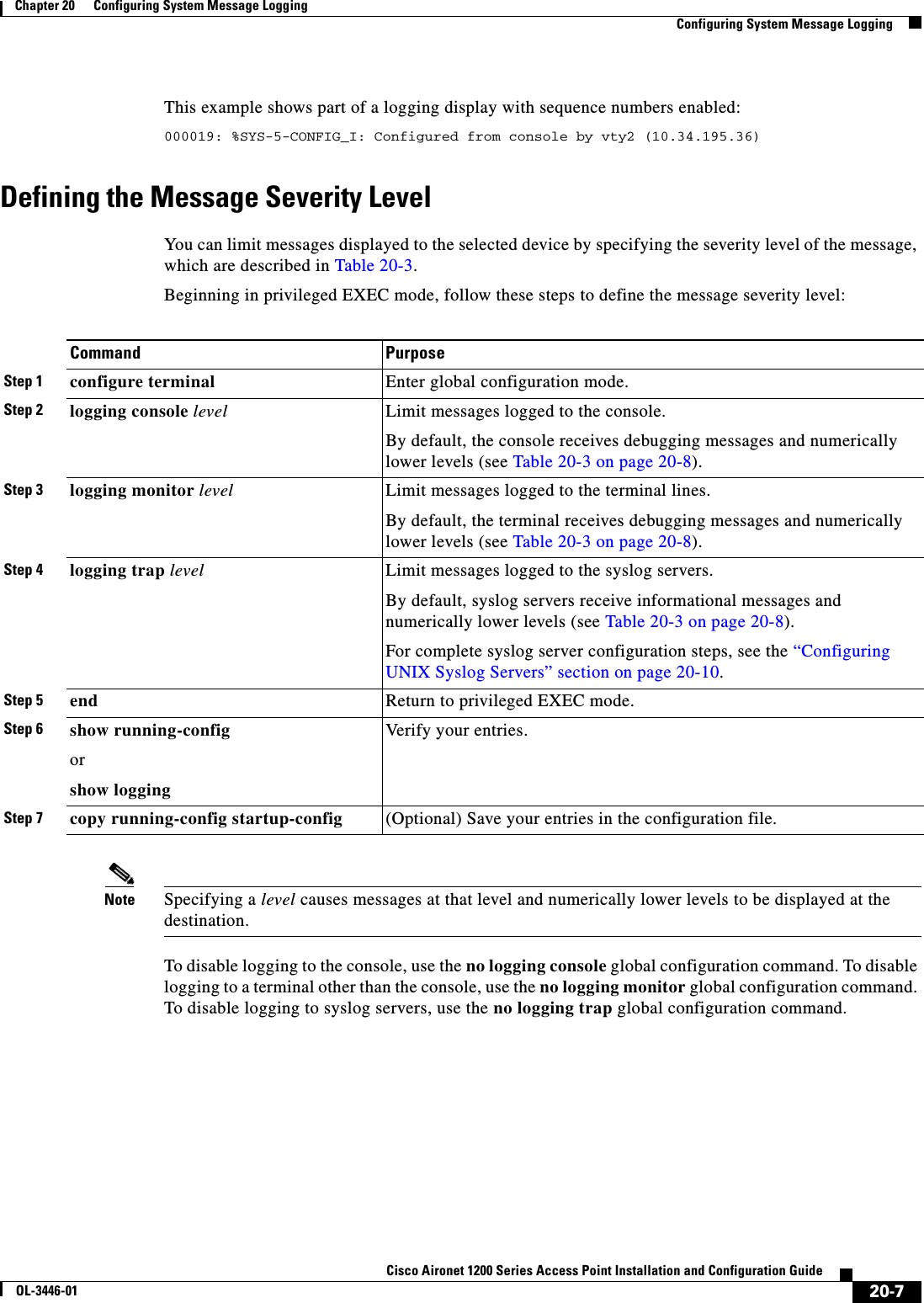
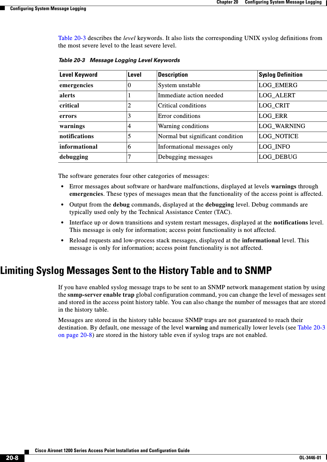
![20-9Cisco Aironet 1200 Series Access Point Installation and Configuration GuideOL-3446-01Chapter 20 Configuring System Message LoggingConfiguring System Message LoggingBeginning in privileged EXEC mode, follow these steps to change the level and history table size defaults:When the history table is full (it contains the maximum number of message entries specified with the logging history size global configuration command), the oldest message entry is deleted from the table to allow the new message entry to be stored.To return the logging of syslog messages to the default level, use the no logging history global configuration command. To return the number of messages in the history table to the default value, use the no logging history size global configuration command.Setting a Logging Rate LimitYou can enable a limit on the number of messages that the access point logs per second. You can enable the limit for all messages or for messages sent to the console, and you can specify that messages of a specific severity are exempt from the limit.Beginning in privileged EXEC mode, follow these steps to enable a logging rate limit:To disable the rate limit, use the no logging rate-limit global configuration command.Command PurposeStep 1 configure terminal Enter global configuration mode.Step 2 logging history level11. Table 20-3 lists the level keywords and severity level. For SNMP usage, the severity level values increase by 1. For example, emergenciesequal 1, not 0, and critical equals 3, not 2.Change the default level of syslog messages stored in the history file and sent to the SNMP server.See Table 20-3 on page 20-8 for a list of level keywords.By default, warnings,errors,critical,alerts, and emergencies messages are sent.Step 3 logging history size number Specify the number of syslog messages that can be stored in the history table.The default is to store one message. The range is 1 to 500 messages.Step 4 end Return to privileged EXEC mode.Step 5 show running-config Verify your entries.Step 6 copy running-config startup-config (Optional) Save your entries in the configuration file.Command PurposeStep 1 configure terminal Enter global configuration mode.Step 2 logging rate-limit seconds[all | console][except severity]Enable a logging rate limit in seconds.•(Optional) Apply the limit to all logging or only to messages logged to the console.•(Optional) Exempt a specific severity from the limit.Step 3 end Return to privileged EXEC mode.Step 4 copy running-config startup-config (Optional) Save your entries in the configuration file.](https://usermanual.wiki/Cisco-Systems/102053.CRN-27004-Question-6-AP-user-manual/User-Guide-441628-Page-275.png)
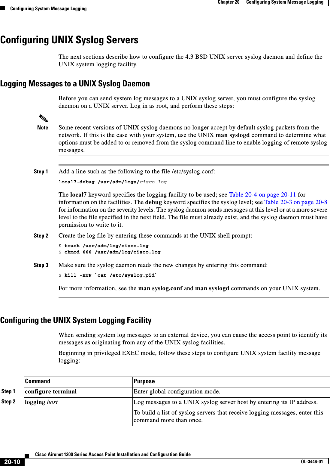
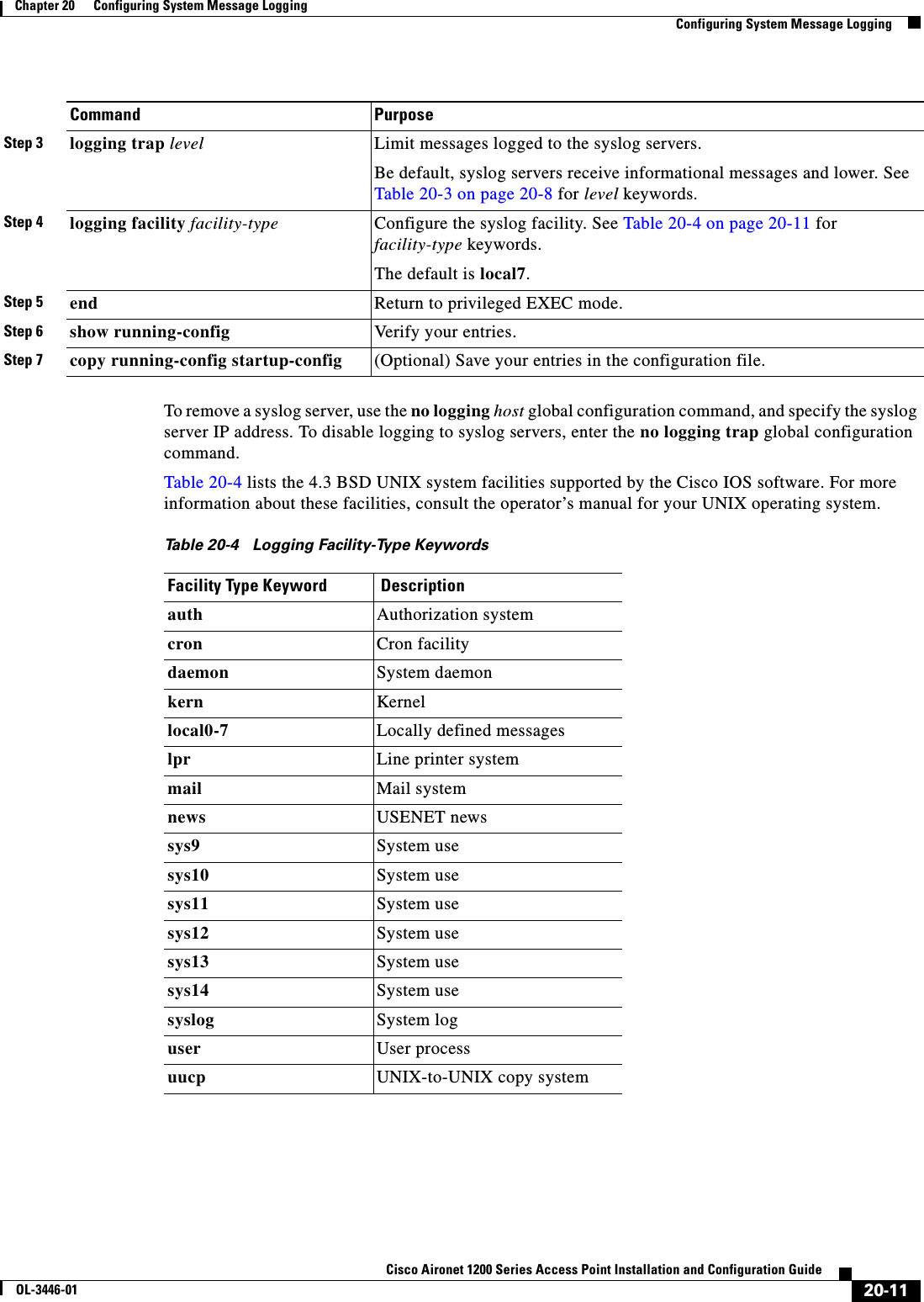
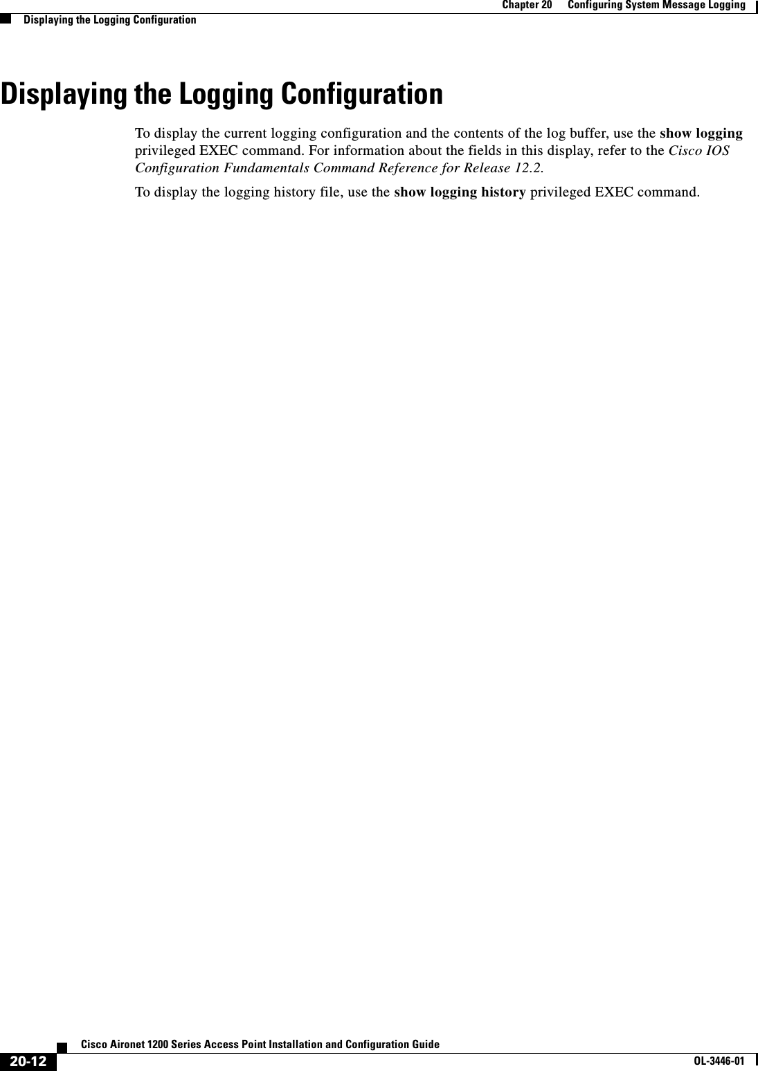
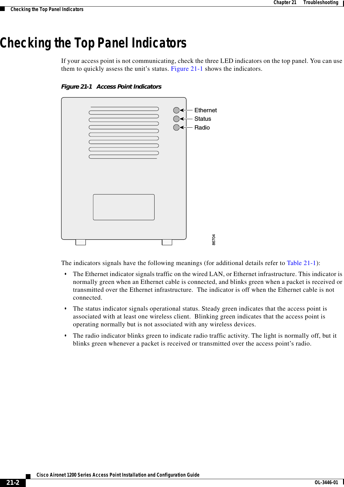
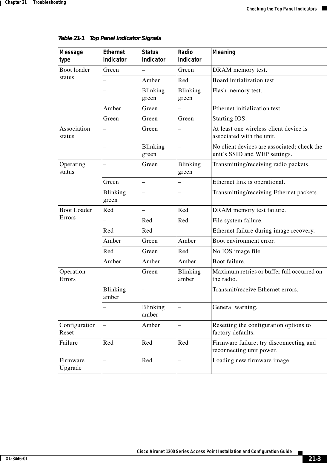
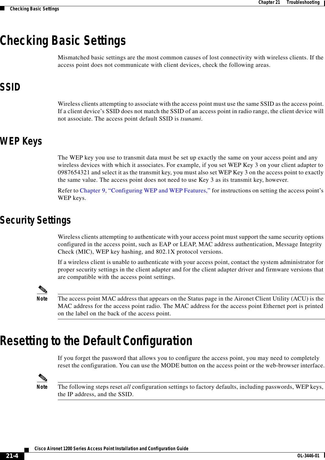
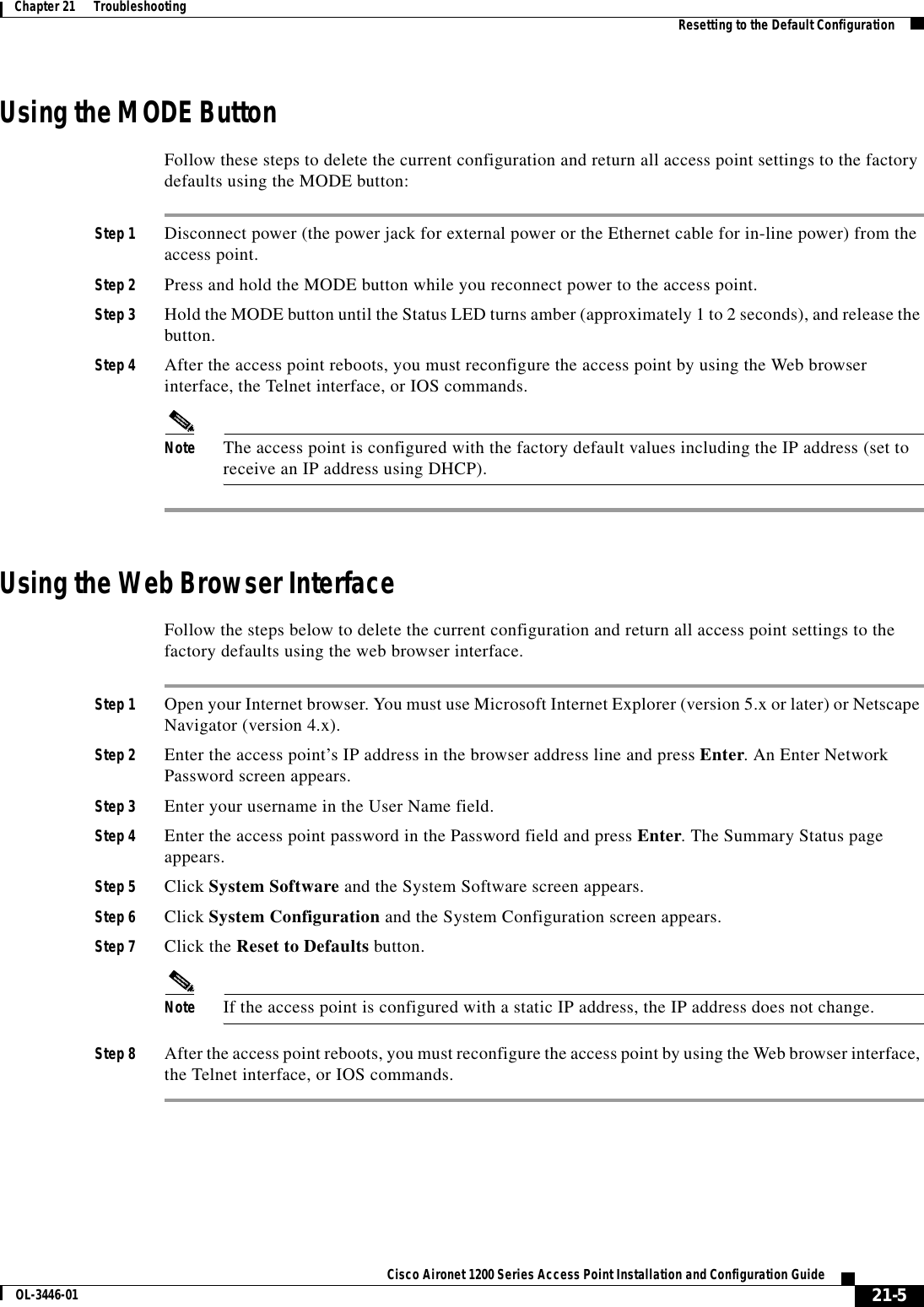
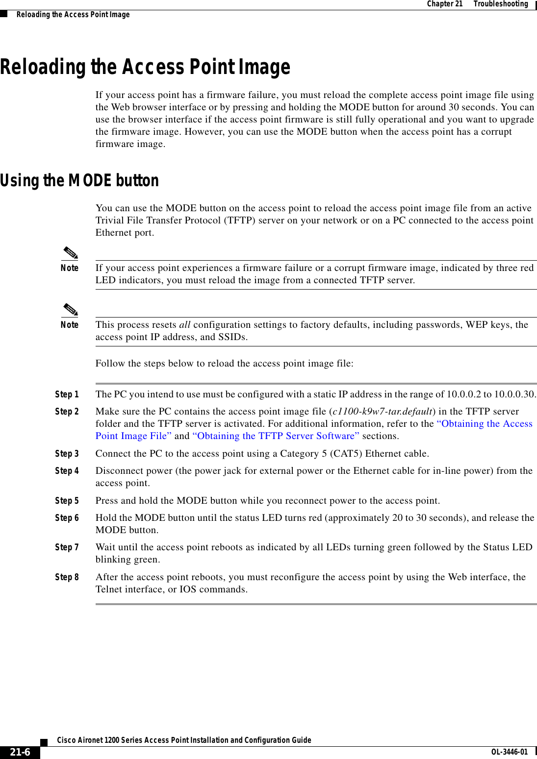
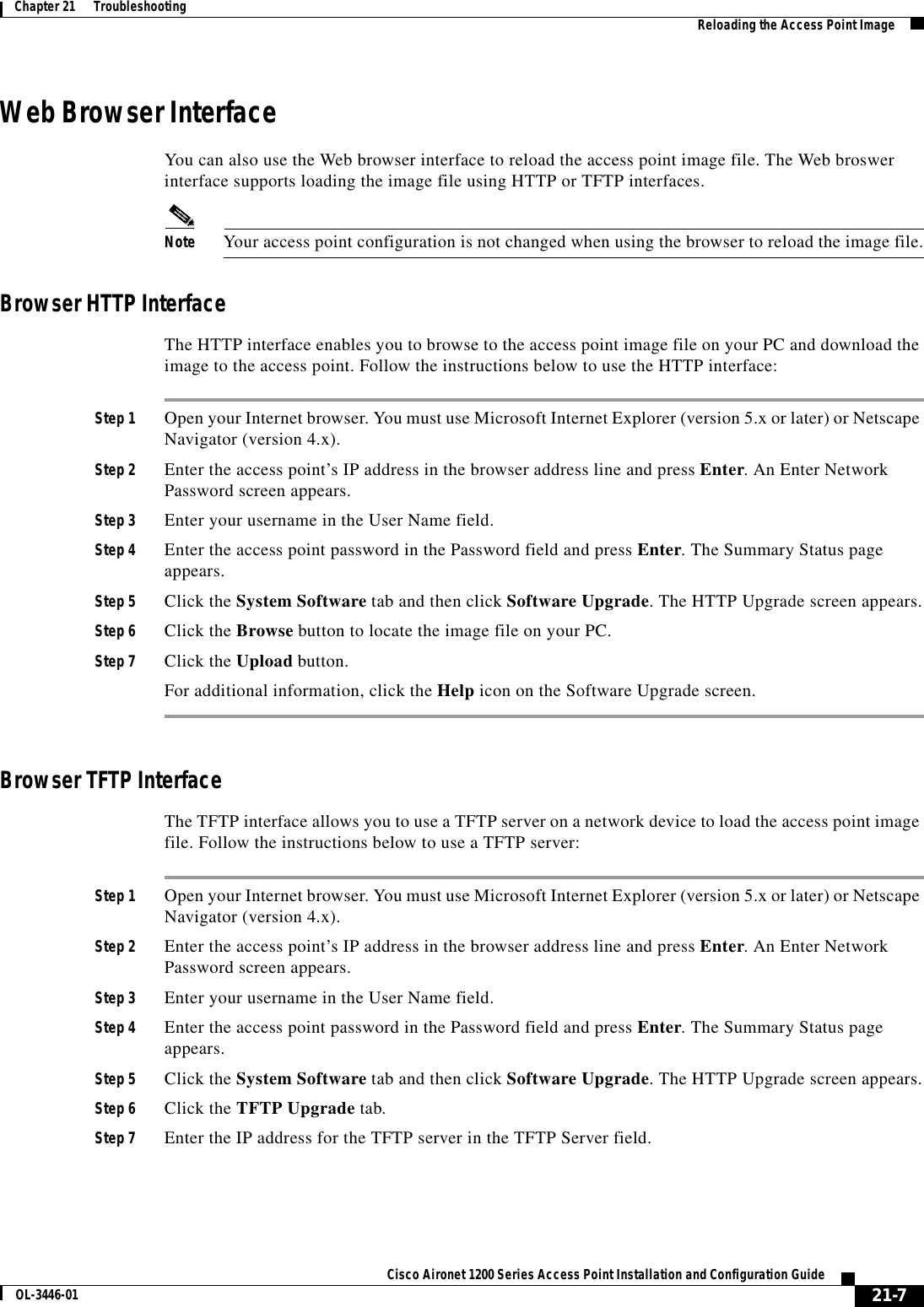
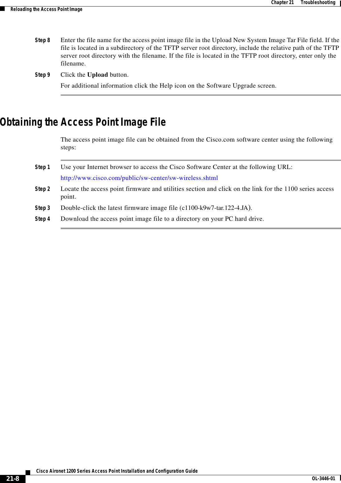

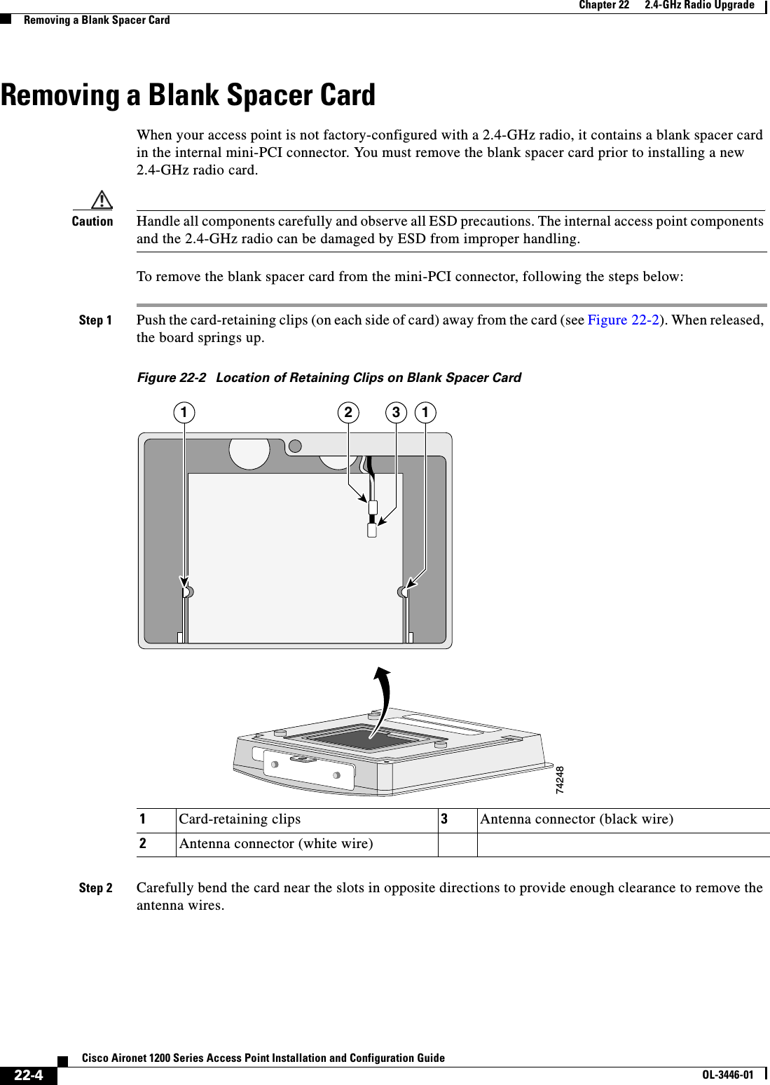
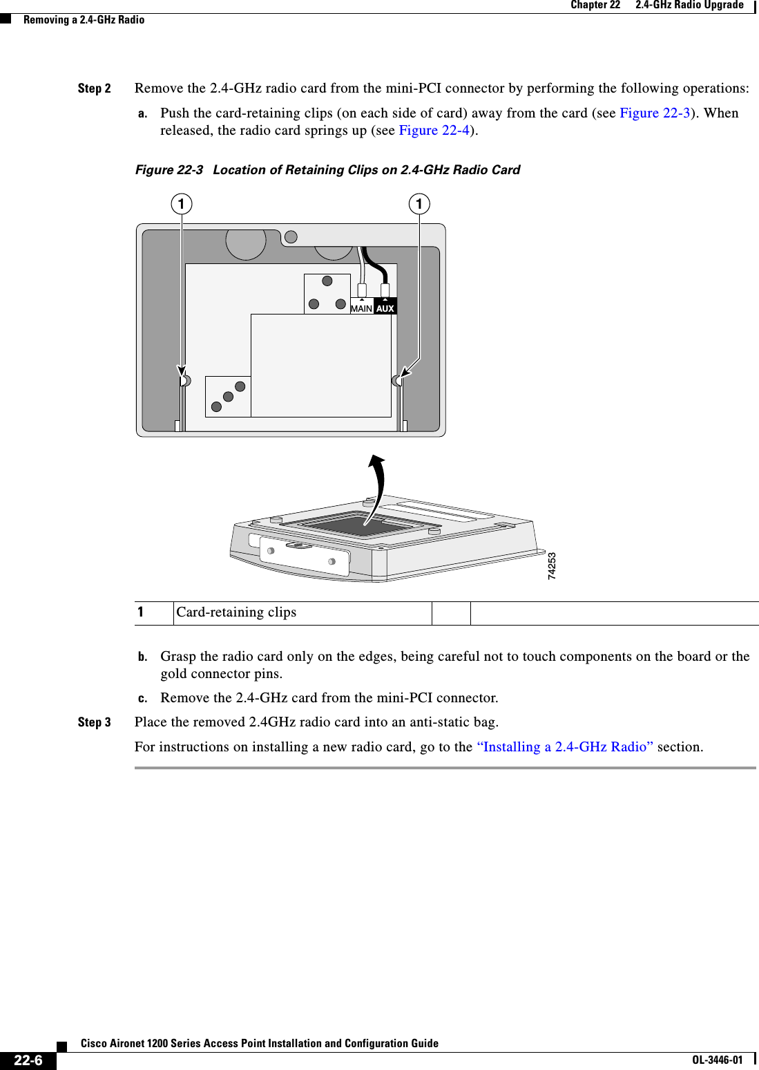
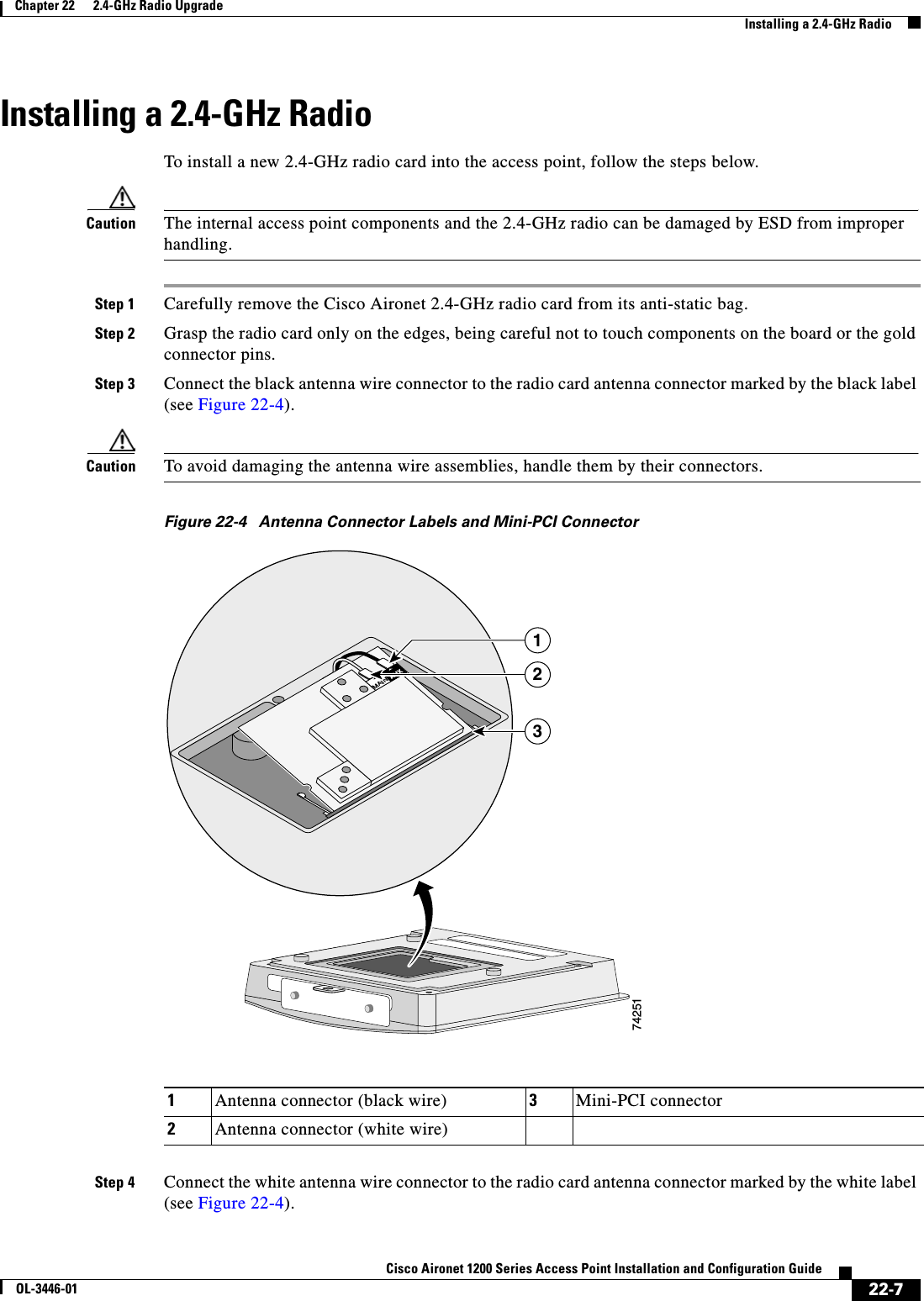
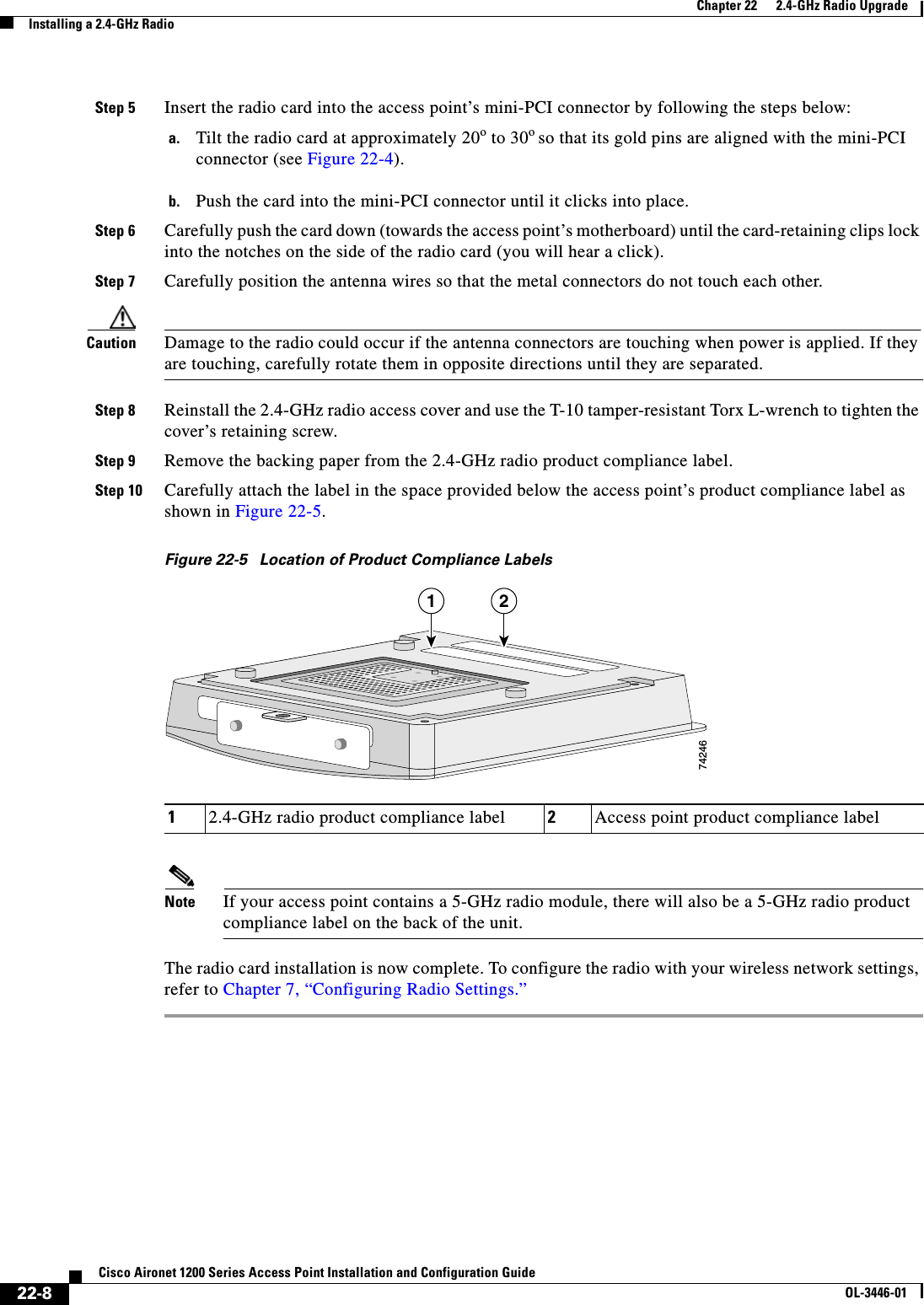
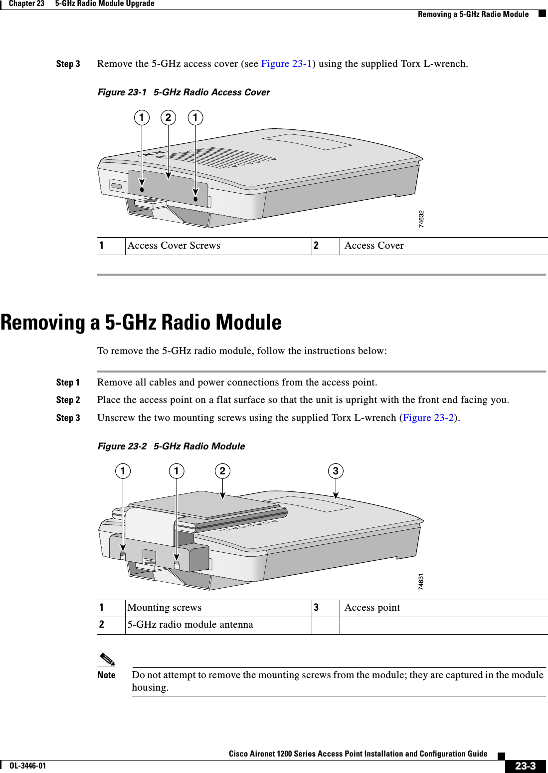
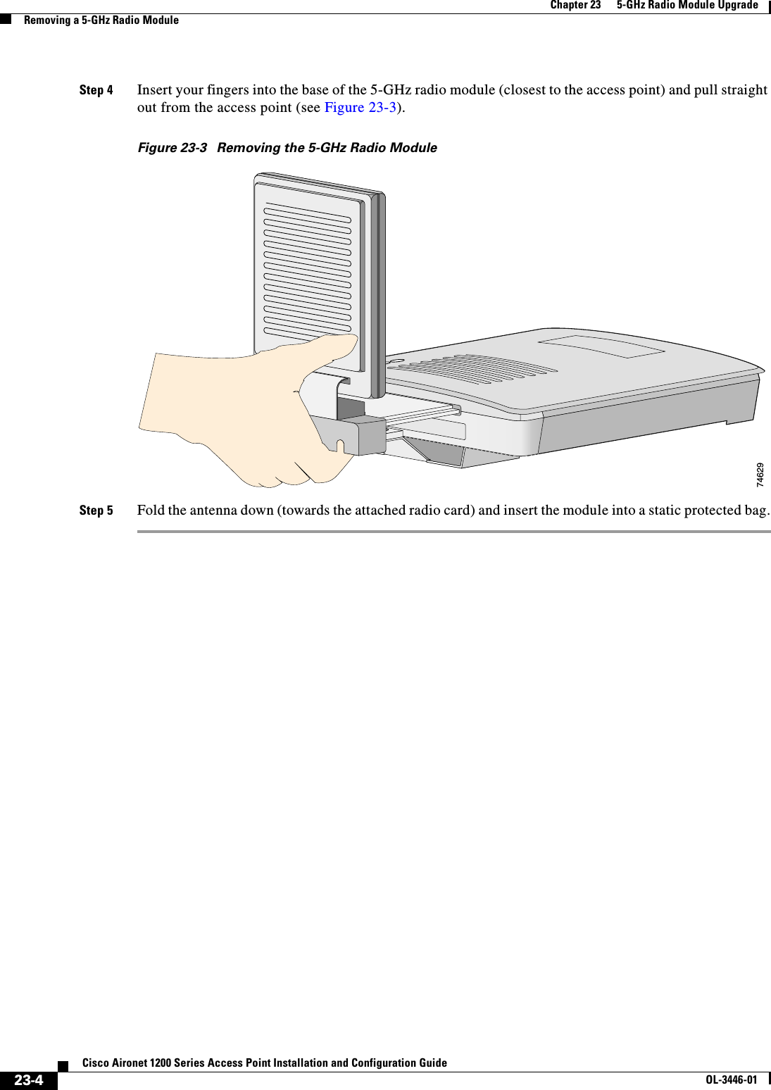
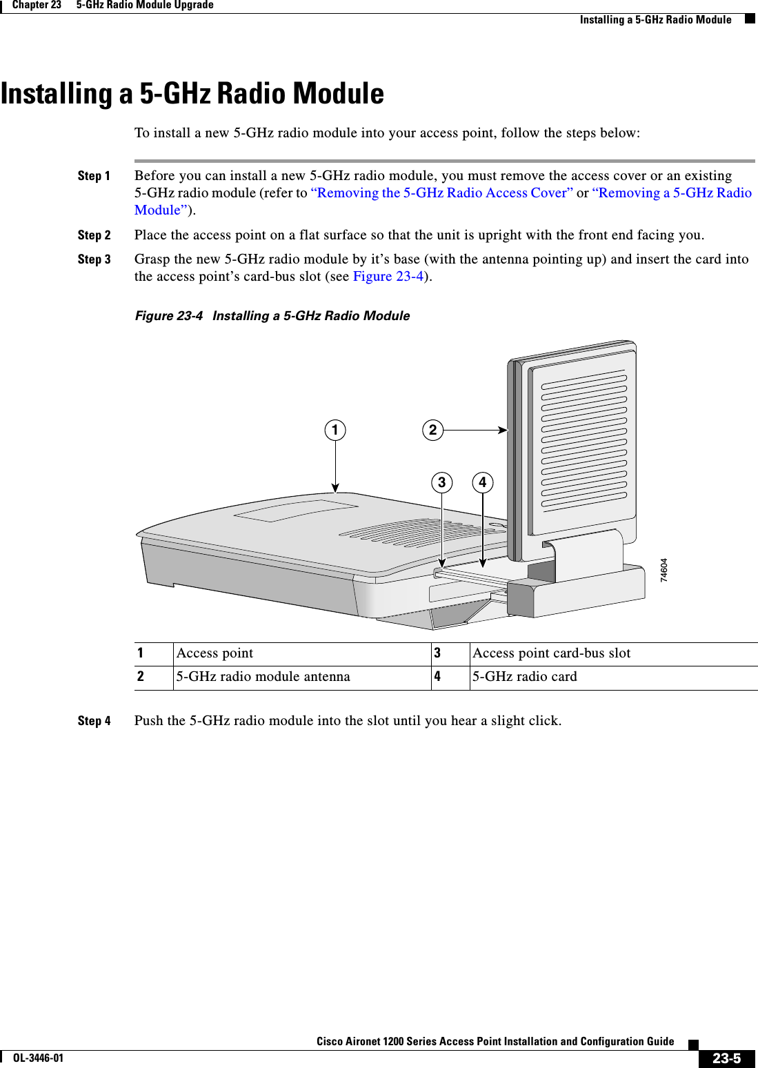
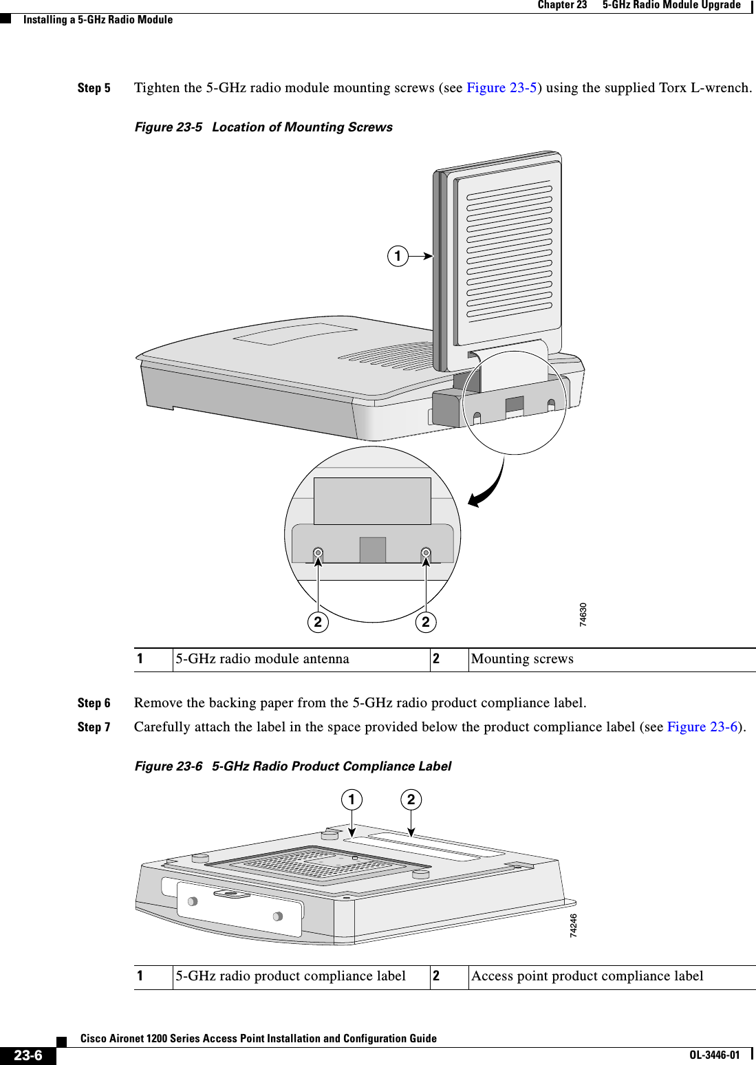


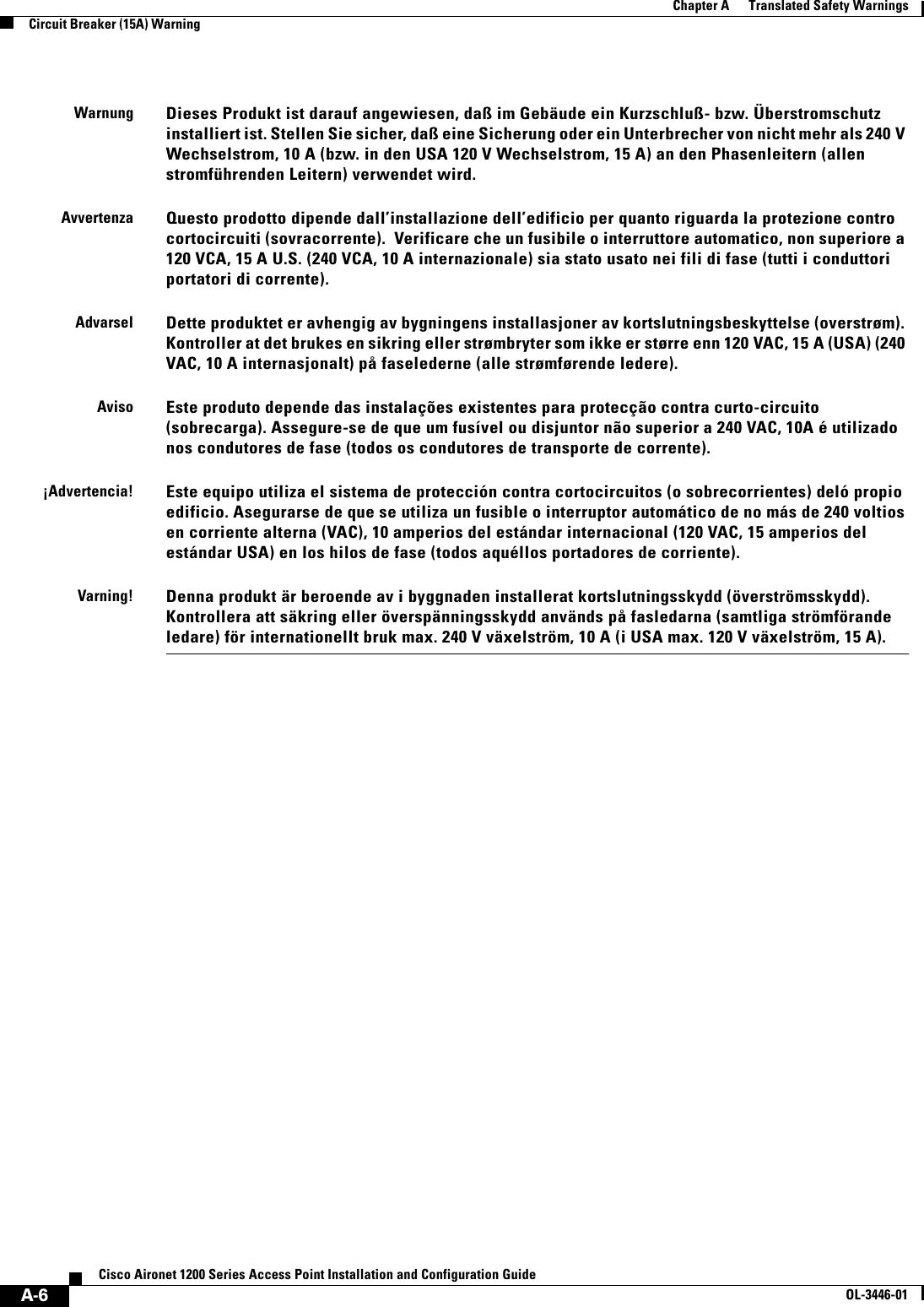
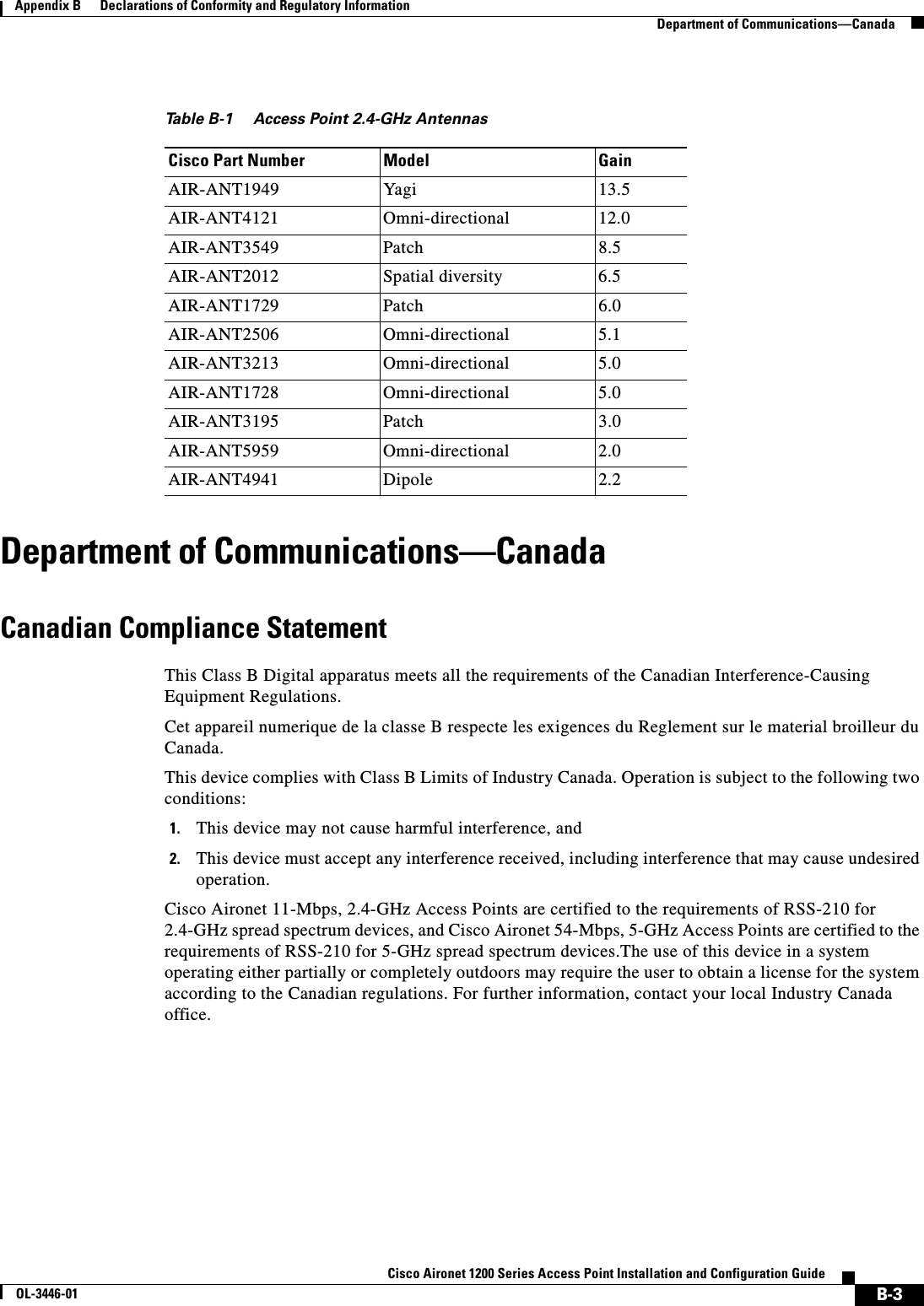
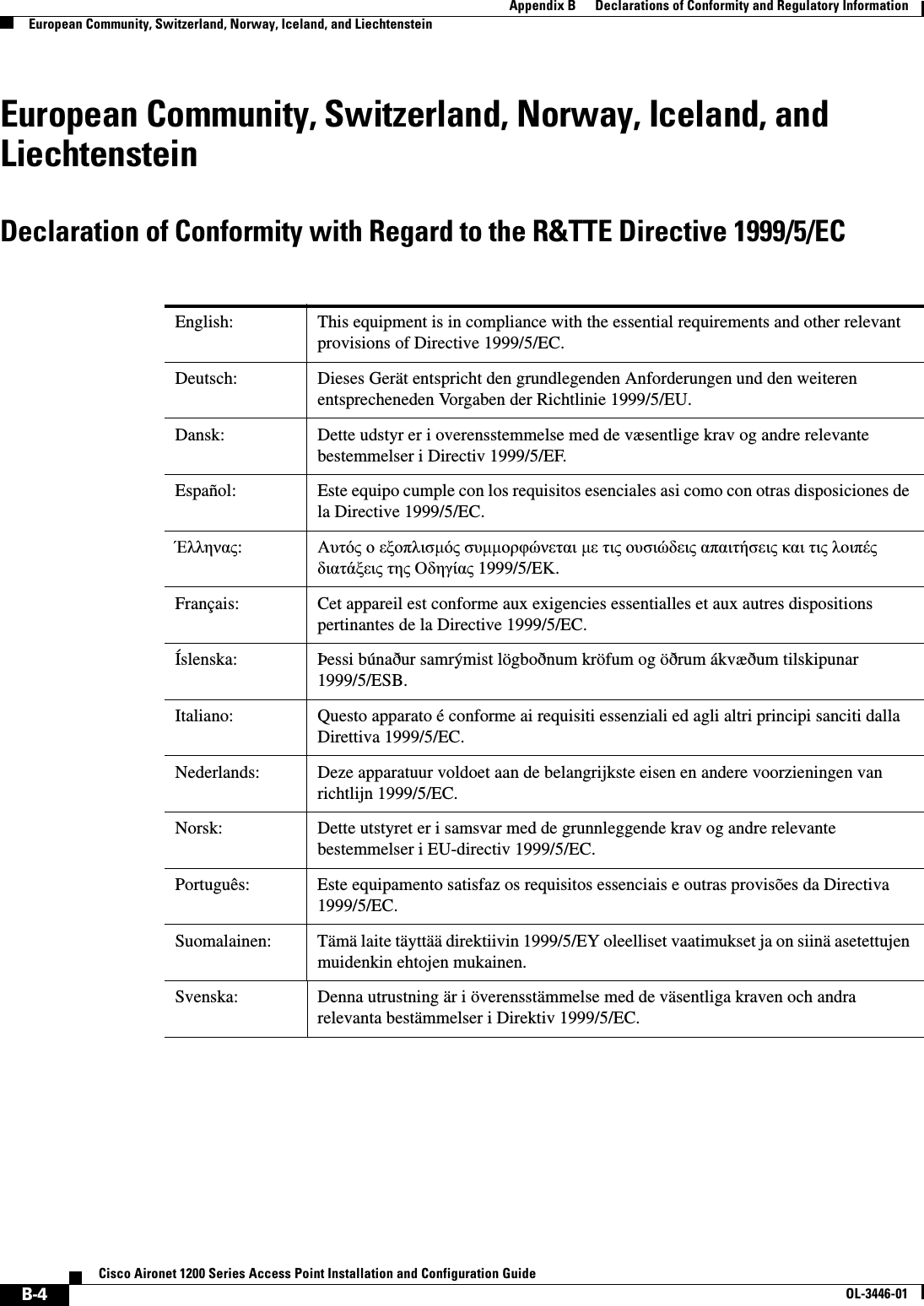
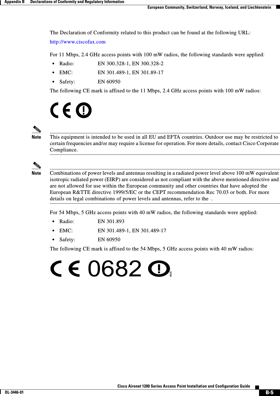
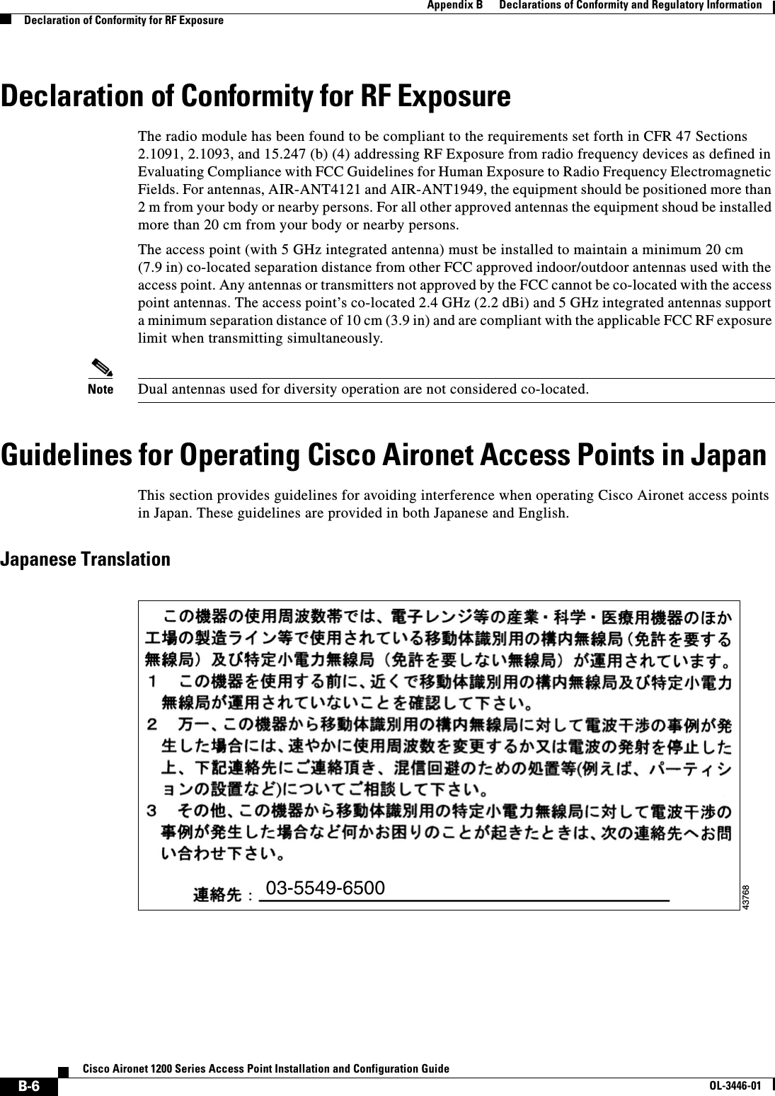

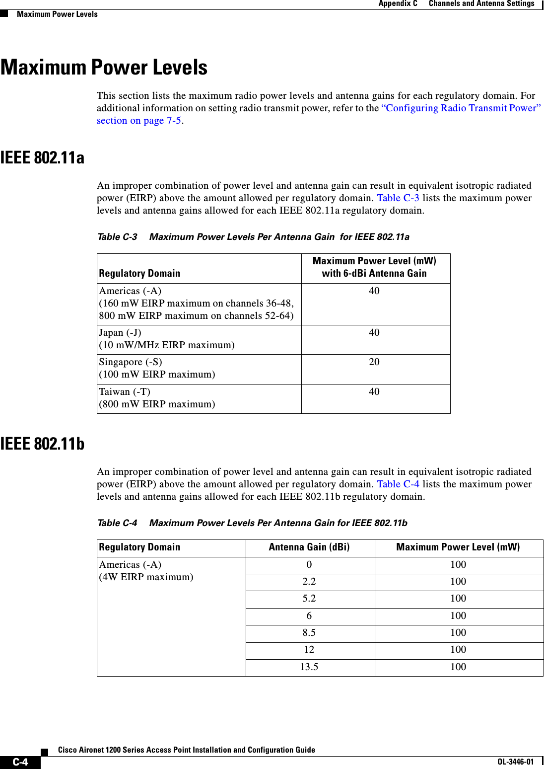
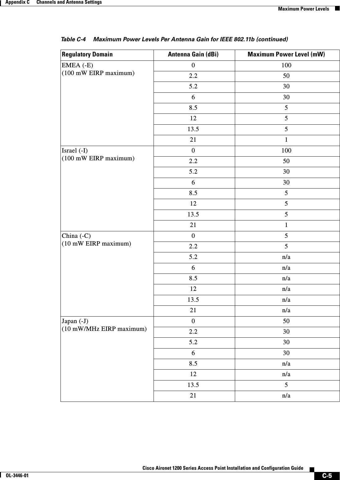

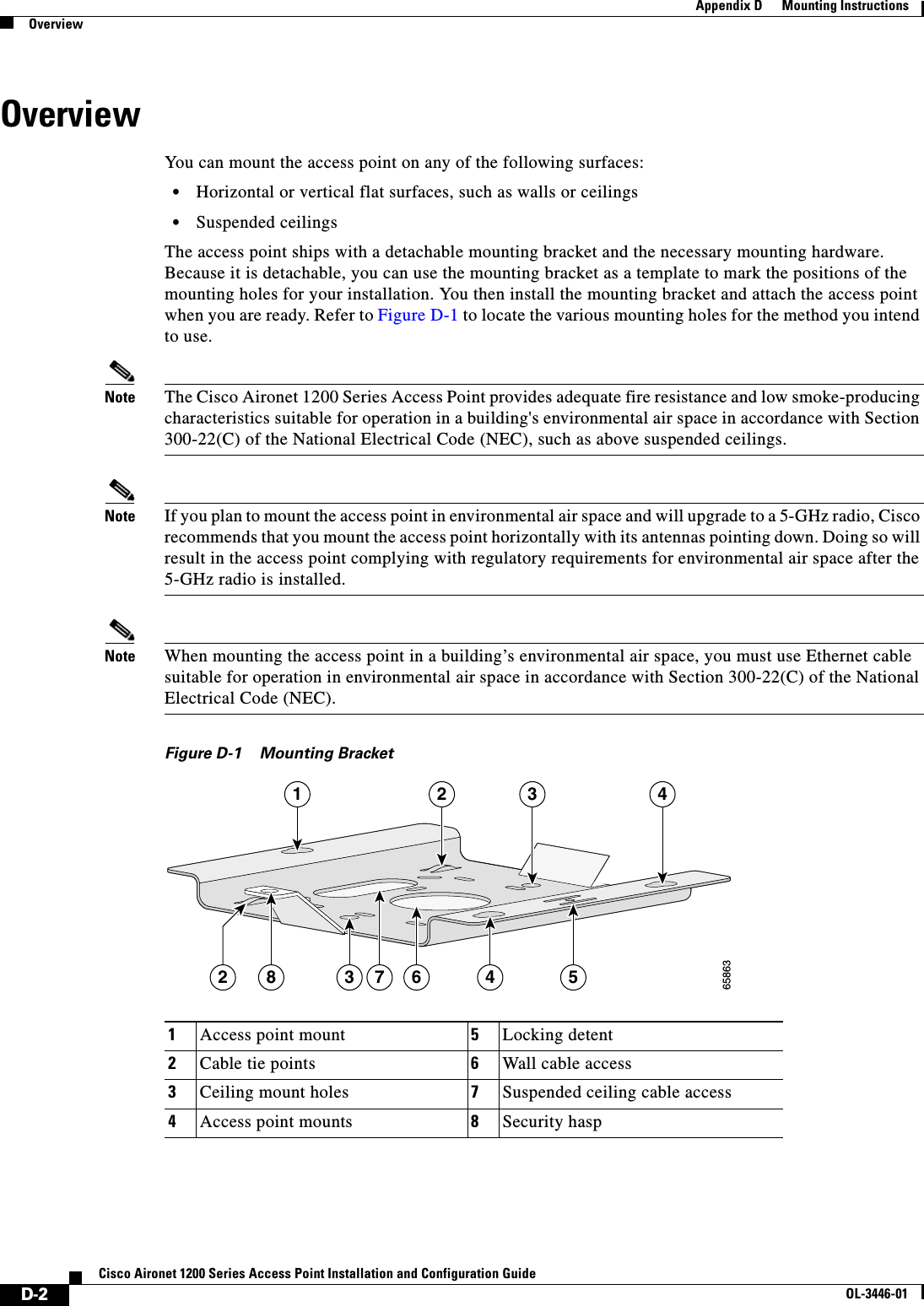
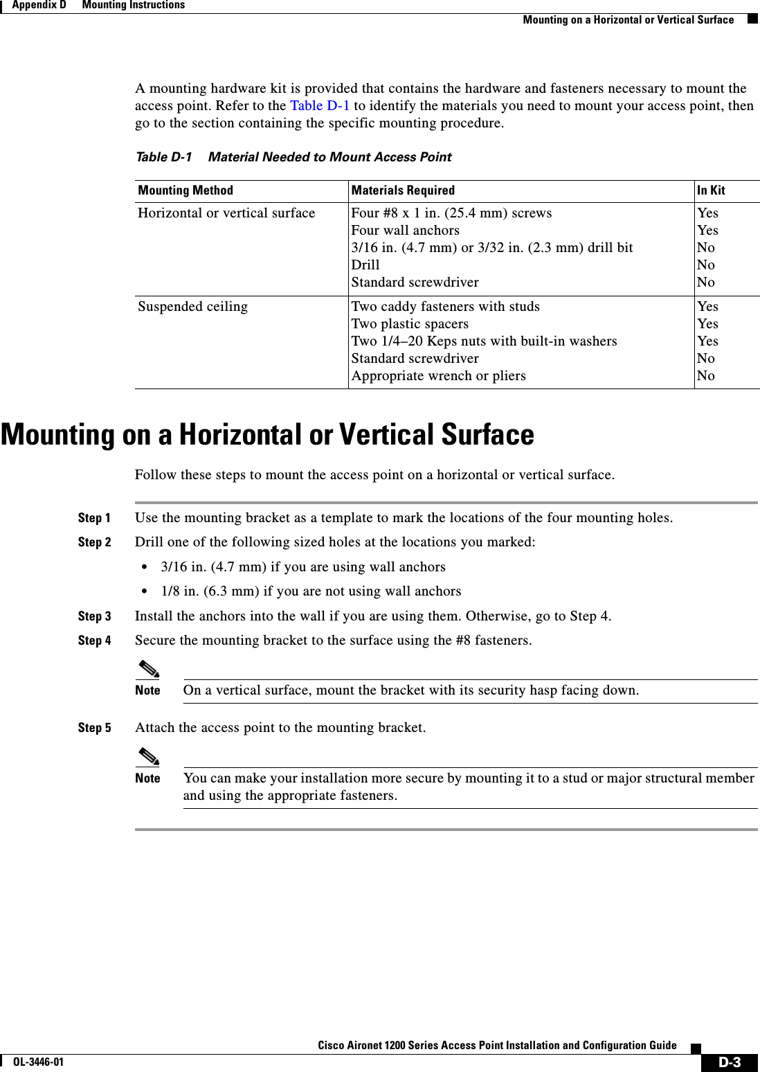
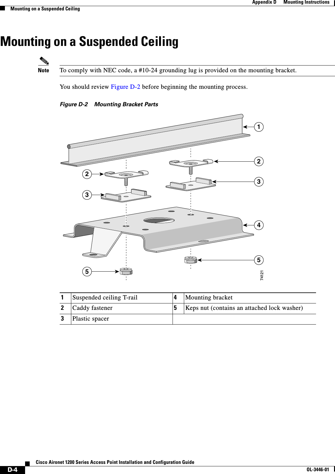

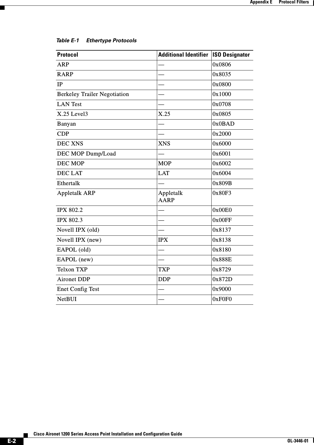
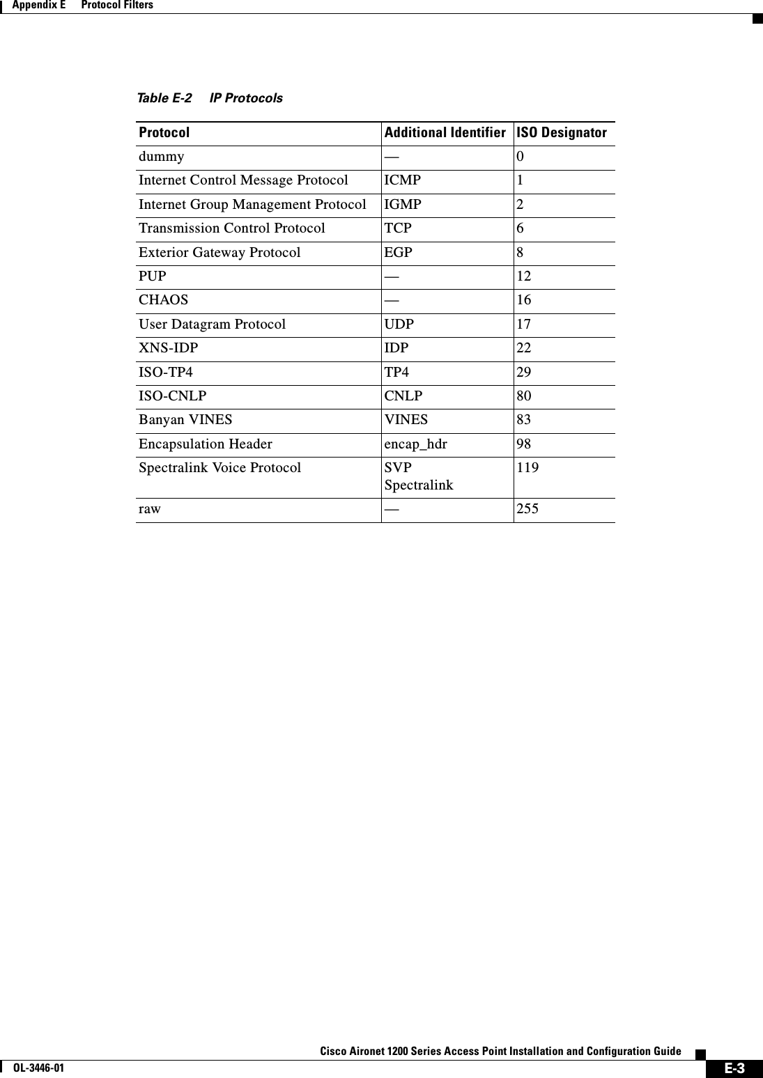
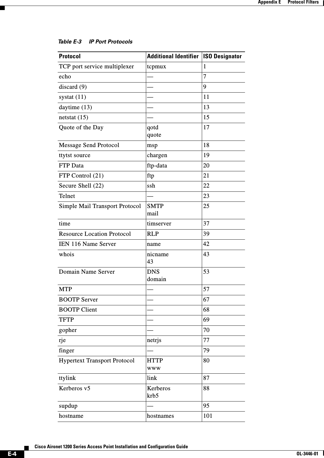
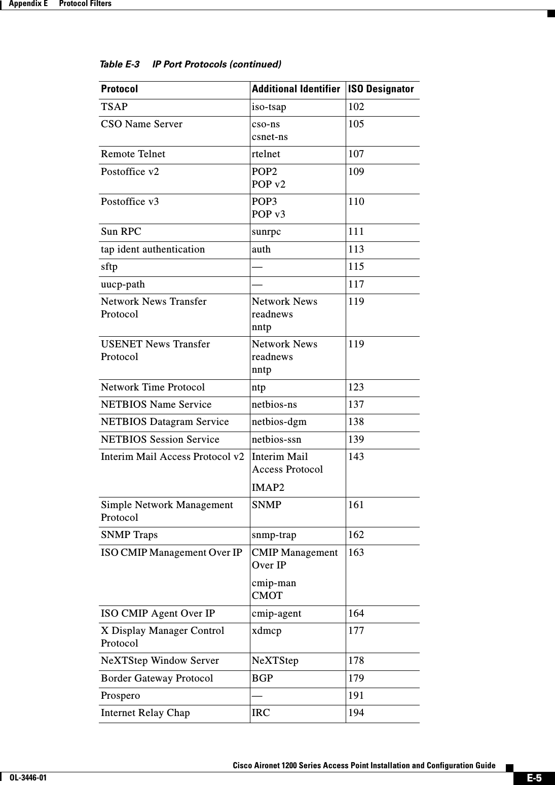
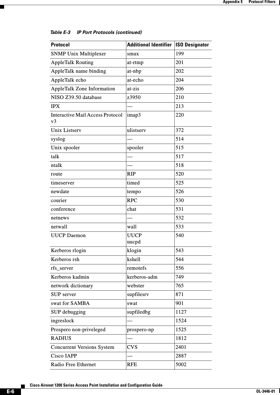
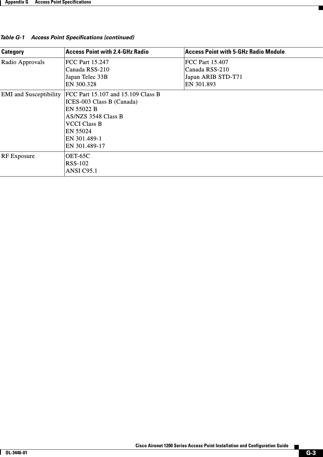

![H-1Cisco Aironet 1200 Series Access Point Installation and Configuration GuideOL-3446-01APPENDIXHError and Event MessagesThis appendix lists the CLI error and event messages. Table H-1 lists the errors and events and provides an explanation and recommended action for each message.Table H-1 Error and Event MessagesMessage Explanation Recommended ActionSoftware Auto Upgrade MessagesSW_AUTO_UPGRADE-FATAL: Attempt to upgrade software failed, software on Flash may be deleted. Please copy software into Flash. Auto upgrade of the software failed. The software on the Flash memory might have been deleted. Copy software into the Flash memory. Copy software before rebooting the unit. SW_AUTO_UPGRADE-7-FAILURE: dhcp_client_start_stop failed Auto upgrade of the software failed due to error in starting/stopping DHCP client process.Copy the error message exactly as it appears and report it to your technical support representative. SW_AUTO_UPGRADE-7-FAILURE: Failed to obtain ip addr from dhcp server Auto upgrade of the software failed. Copy the error message exactly as it appears and report it to your technical support representative.SW_AUTO_UPGRADE-7-FAILURE: boot_file_pathent creation failed Auto upgrade of the software failed due to error in creation of pathent (internal data structure).Copy the error message exactly as it appears and report it to your technical support representative.Association Management MessagesDOT11-3-BADSTATE: [mac-address] [chars] [chars] -> [chars]802.11 Association and management uses a table-driven state machine to keep track and transition an Association through various states. A state transition occurs when an Association receives one of many possible events. When this error occurs, it means that an Association received an event that it did not expect while in this state.The system can continue but may lose the Association that generates this error. Copy the message exactly as it appears and report it to your technical service representative.DOT11-6-ASSOC: Interface [interface], Station [char] [mac] AssociatedA station associated to an access point. None.DOT11-6-ADD: Interface [interface], Station [mac] Associated to Parent [mac]A station associated to an access point. None.](https://usermanual.wiki/Cisco-Systems/102053.CRN-27004-Question-6-AP-user-manual/User-Guide-441628-Page-343.png)
![H-2Cisco Aironet 1200 Series Access Point Installation and Configuration GuideOL-3446-01Appendix H Error and Event MessagesDOT11-6-DISASSOC: Interface [interface], Deauthenticating Station [mac] [char]A station disassociated from an access point.None.DOT11-6-ROAMED: Station [mac-address] Roamed to [mac-address]A station has roamed to a new access point.None.Proxy Mobile IP Subsystem MessagesPMIP-3-REG_FAIL: Mobile Node 10.4.1.3 mobile ip registration failedWhen a mobile node (MN) moves to a foreign network, the access point registers the MN to its Home Agent. This message indicates that the registration failed.Check for correct configuration of Mobile IP agents and the access point.PMIP-3-REG_AUTH_FAIL: Mobile Node 10.4.1.3 registration failed due to authentication failureWhen a mobile node (MN) moves to a foreign network, the access point registers the MN to its Home Agent. This message indicates that the registration failed because the HA or FA failed to authenticate each other or the MN.Make sure the correct authentication information is configured on the Home Agent, the Foreign Agent, and the access point.PMIP-3-REG_FA_FAIL: Mobile Node 10.4.1.3 registration failed due to Foreign Agent denialWhen a Mobile node (MN) moves to a foreign network, the access point registers the MN to its Home Agent. This message indicates that the registration was denied by the Foreign Agent.Make sure the correct authentication information is configured on the Home Agent, the Foreign Agent, and the access point.PMIP-3-REG_HA_FAIL: Mobile Node 10.4.1.3 registration failed due to Home Agent denialWhen a Mobile node (MN) moves to a foreign network, the access point registers the MN to its Home Agent. This message indicates that the registration was denied by the Home Agent.Make sure the correct authentication information is configured on the Home Agent, the Foreign Agent, and the access point.PMIP-3-AUTH_UNAVAIL: Authentication for 10.4.1.3 unavailableProxy Mobile IP failed to obtain the Mobile Node's authentication information either locally or from a AAA server.Make sure the correct Mobile Node information is configured locally or on the AAA server.PMIP-3-HAFA_UNAVAIL: No response from the Mobile IP Agent to our registration requestsProxy Mobile IP failed to access the Home or Foreign Agent while trying to register the Mobile Node.Make sure the HA or FA is not down or is network inaccessible. Also check that the subnet map information regarding the Home Agent is correct.PMIP-6-HAFA_DOWN: Mobile IP Agent 10.4.1.1 is down or unavailableMobile IP Home or Foreign agent has gone down or is inaccessible to the access point.Make sure there is at least one Home and Foreign Agent configured on that subnet and is accessible to the access point.PMIP-3-AAP_UNAVAIL: Authoritative Access Point is unavailableThe authoritative access point cannot be reached to obtains subnet map table.Make sure all the access points have the same information regarding Authoritative and regular access points.PMIP-6-START: Proxy Mobile IP services has startedProxy Mobile IP service has started. None.Table H-1 Error and Event Messages (continued)Message Explanation Recommended Action](https://usermanual.wiki/Cisco-Systems/102053.CRN-27004-Question-6-AP-user-manual/User-Guide-441628-Page-344.png)
![H-3Cisco Aironet 1200 Series Access Point Installation and Configuration GuideOL-3446-01Appendix H Error and Event MessagesPMIP-6-STOP: Proxy Mobile IP services have stoppedProxy Mobile IP service has stopped. None.PMIP-6-REPEATER_STOP: AP is now operating as a repeater, disabling Proxy Mobile IP servicesProxy Mobile IP does not run on repeaters or workgroup bridges, and it is disabled automatically when the access point is in repeater mode.None.Unzip MessagesSOAP-4-UNZIP_OVERFLOW: Failed to unzip Flash:/c1200-k9w7-mx.122-3.6.JA1/html/level15/ap_xxx.htm.gz, exceeds maximum uncompressed html sizeThe HTTP server cannot retrieve a compressed file in response to an HTTP GET request because the size of the file is too large for the buffers used in the uncompression process.Make sure file is a valid HTML page. If so, you'll have to copy an uncompressed version of the file into Flash to retrieve it through HTTP.802.11 Subsystem MessagesDOT11-6-FREQ_INUSE: Radio frequency [int] is in useWhen scanning for an unused frequency, the unit recognized another radio using the displayed frequency.None.DOT11-6-FREQ_USED: Radio frequency [int] selectedAfter scanning for an unused frequency, the unit selected the displayed frequency.None.DOT11-4-VERSION_MISMATCH: Require radio version [hex].[int], found version [hex].[int]When starting the radio, the wrong firmware version was found. The radio will be loaded with the required version.None.DOT11-2-VERSION_INVALID: Unable to find required radio version [hex].[int]When trying to re-flash the radio firmware, the access point recognized that the radio firmware packaged with the IOS firmware had the incorrect version. None.DOT11-4-NO_SSID: No SSIDs configured, radio not startedAll SSIDs were deleted from the configuration. At least one must be configured for the radio to run.Configure at least one SSID on the access point.DOT11-4-FLASHING_RADIO: Flashing the radio firmware ([chars])The radio has been stopped to load new firmware.None.DOT11-2-NO_FIRMWARE: No radio firmware file ([chars]) was foundWhen trying to Flash new firmware into the radio, the file for the radio was not found in the Flash file system.The wrong image has been loaded into the unit. Locate the correct image based on the type of radio used.DOT11-2-BAD_FIRMWARE: Radio firmware file ([chars]) is invalidWhen trying to Flash new firmware into the radio, the file was found to be invalid.Put the correct firmware image file in the place where the unit is looking.DOT11-4-FLASH_RADIO_DONE: Flashing the radio firmware completedThe radio firmware Flash is complete, and the radio will be restarted with the new firmware.None.DOT11-4-LINK_DOWN: Radio parent lost: [chars]The connection to the parent access point was lost for the displayed reason. The unit will try to find a new parent access point.None.Table H-1 Error and Event Messages (continued)Message Explanation Recommended Action](https://usermanual.wiki/Cisco-Systems/102053.CRN-27004-Question-6-AP-user-manual/User-Guide-441628-Page-345.png)
![H-4Cisco Aironet 1200 Series Access Point Installation and Configuration GuideOL-3446-01Appendix H Error and Event MessagesDOT11-4-CANT_ASSOC: Cannot associate: [chars]The unit could not establish a connection to a parent access point for the displayed reason.Check the configuration of both the parent access point and this unit to make sure the basic settings (SSID, WEP, and others) match.Inter-Access Point Protocol MessagesDOT11-6-ROAMED: Station [mac-address] Roamed to [mac-address]A station has roamed to a new access point.None.DOT11-6-STANDBY_ACTIVE: Standby to Active, Reason = [chars] ([int])The access point is transitioning from standby mode to active mode.None.DOT11-6-ROGUE_AP: Rogue AP [mac-address] reported. Reason: [chars]A station has reported a potential rogue access point for the stated reason.None.SCHED-3-UNEXPECTEDMESSAGE: Unknown message [hex] received (ptr arg [hex], num arg [hex]).A process can register to be notified when various events occur in the router. This message indicates that a process received a message from another process that it does not know how to handle.Copy the error message exactly as it appears, and report it to your technical support representative.SCHED-3-UNEXPECTEDEVENT: Process received unknown event (maj [hex], min [hex]).A process can register to be notified when various events occur in the router. This message indicates that a process received an event that it did not know how to handle.Copy the error message exactly as it appears, and report it to your technical support representative.Table H-1 Error and Event Messages (continued)Message Explanation Recommended Action](https://usermanual.wiki/Cisco-Systems/102053.CRN-27004-Question-6-AP-user-manual/User-Guide-441628-Page-346.png)