Cisco Systems 102055 Cisco Aironet 1242AG Series IEEE 802.11a/b/g AP User Manual ap1240b
Cisco Systems Inc Cisco Aironet 1242AG Series IEEE 802.11a/b/g AP ap1240b
UserManual.wiki
>
Cisco Systems
>
102055 User Manual
Users Manual
Navigation menu
Upload a User Manual
Namespaces
Wiki Guide
HTML
PDF
Info
Views
User Manual
Discussion / Help
Navigation

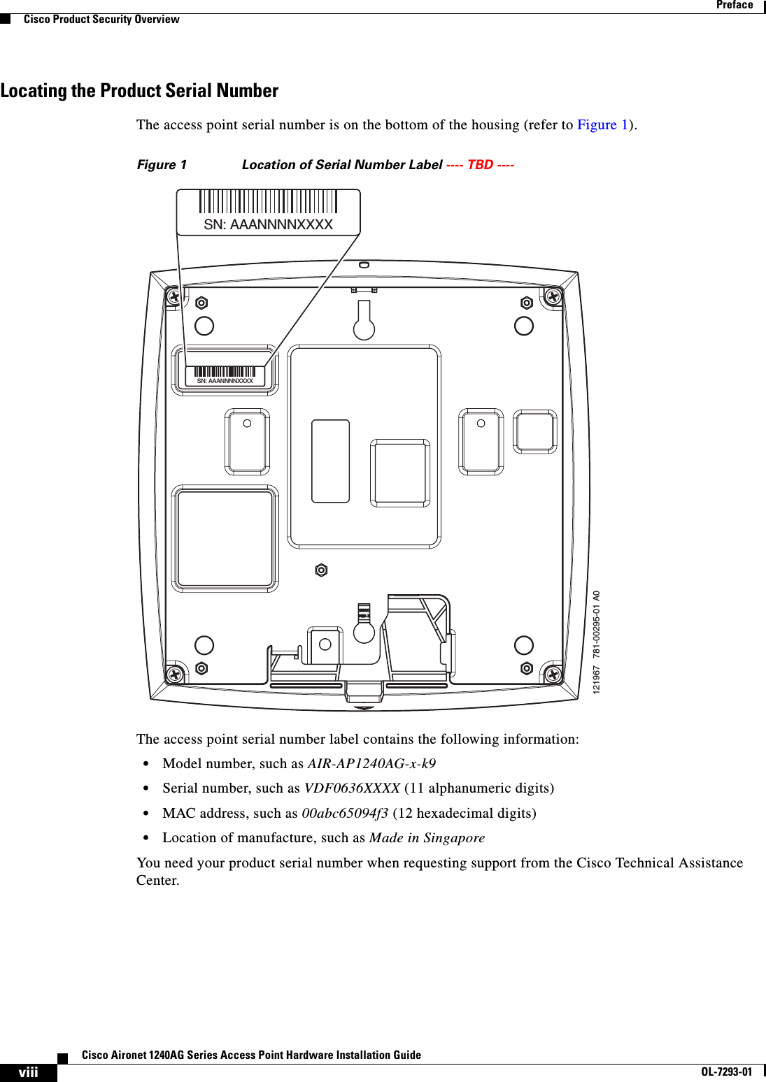
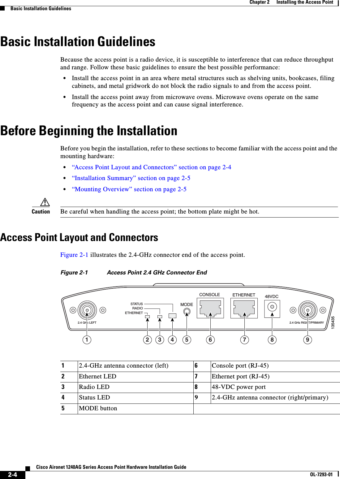
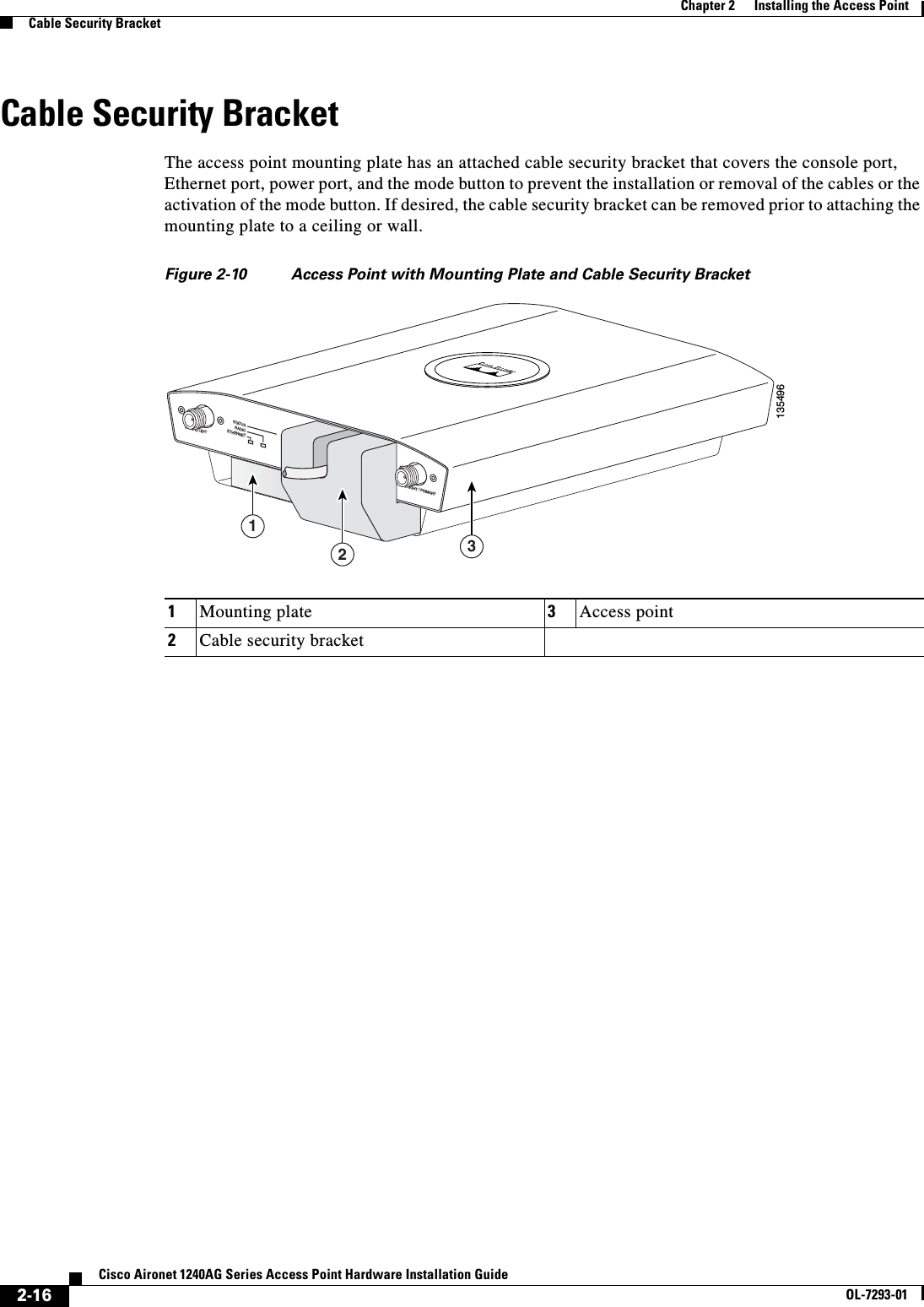
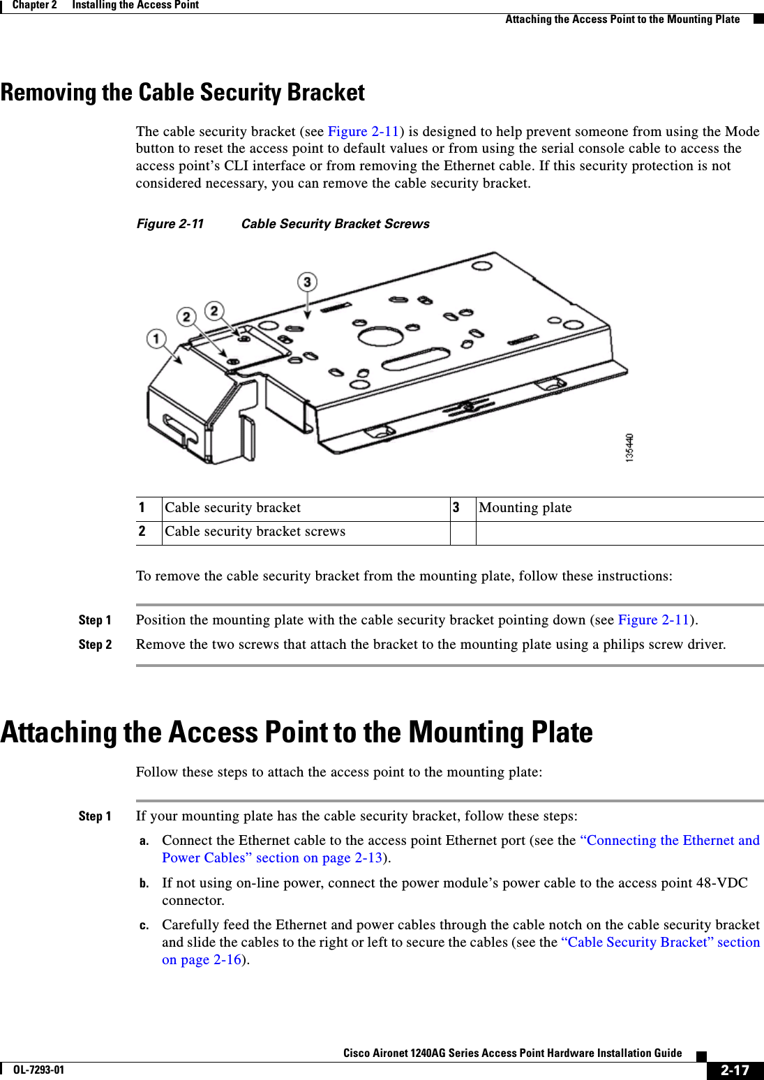
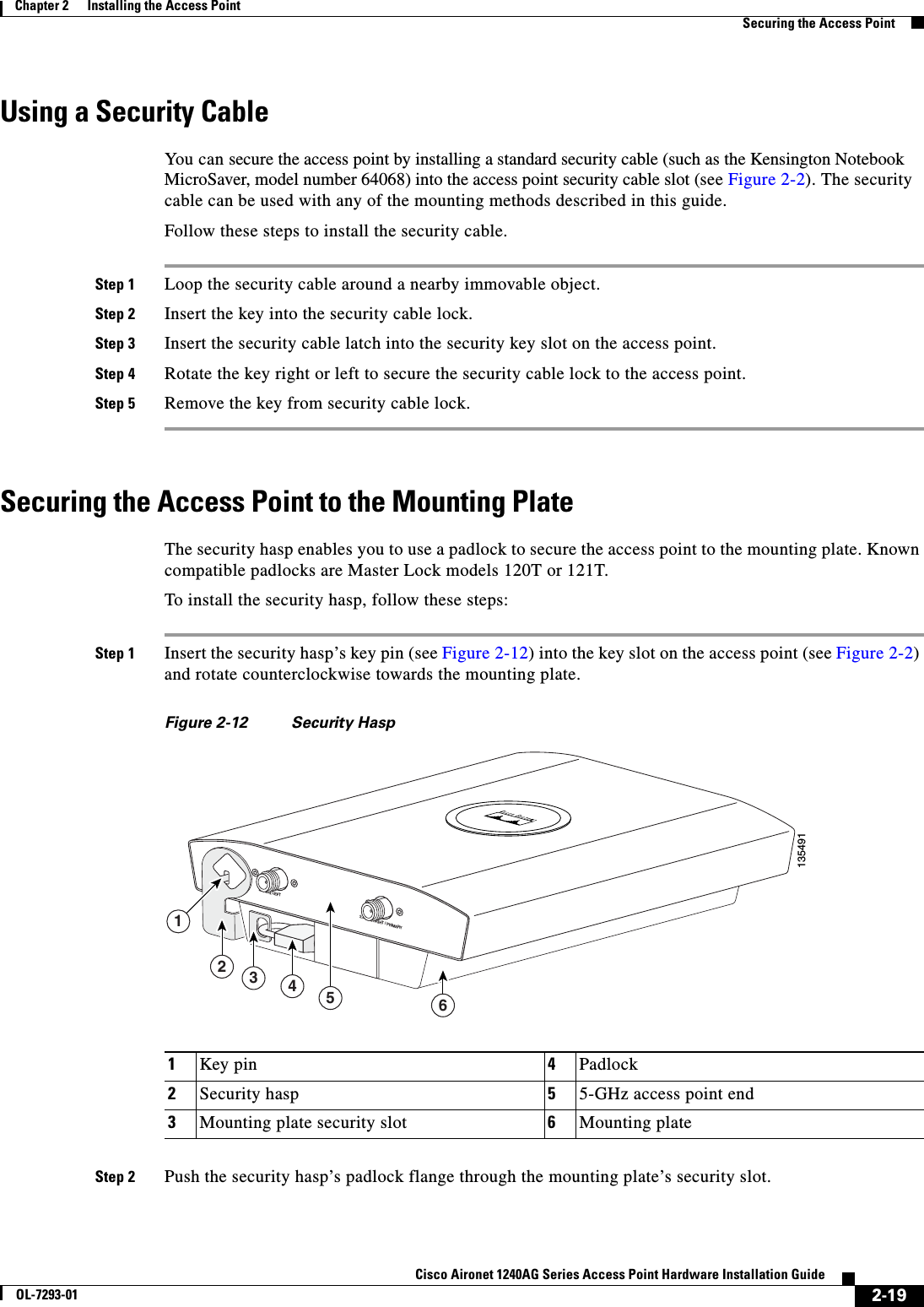
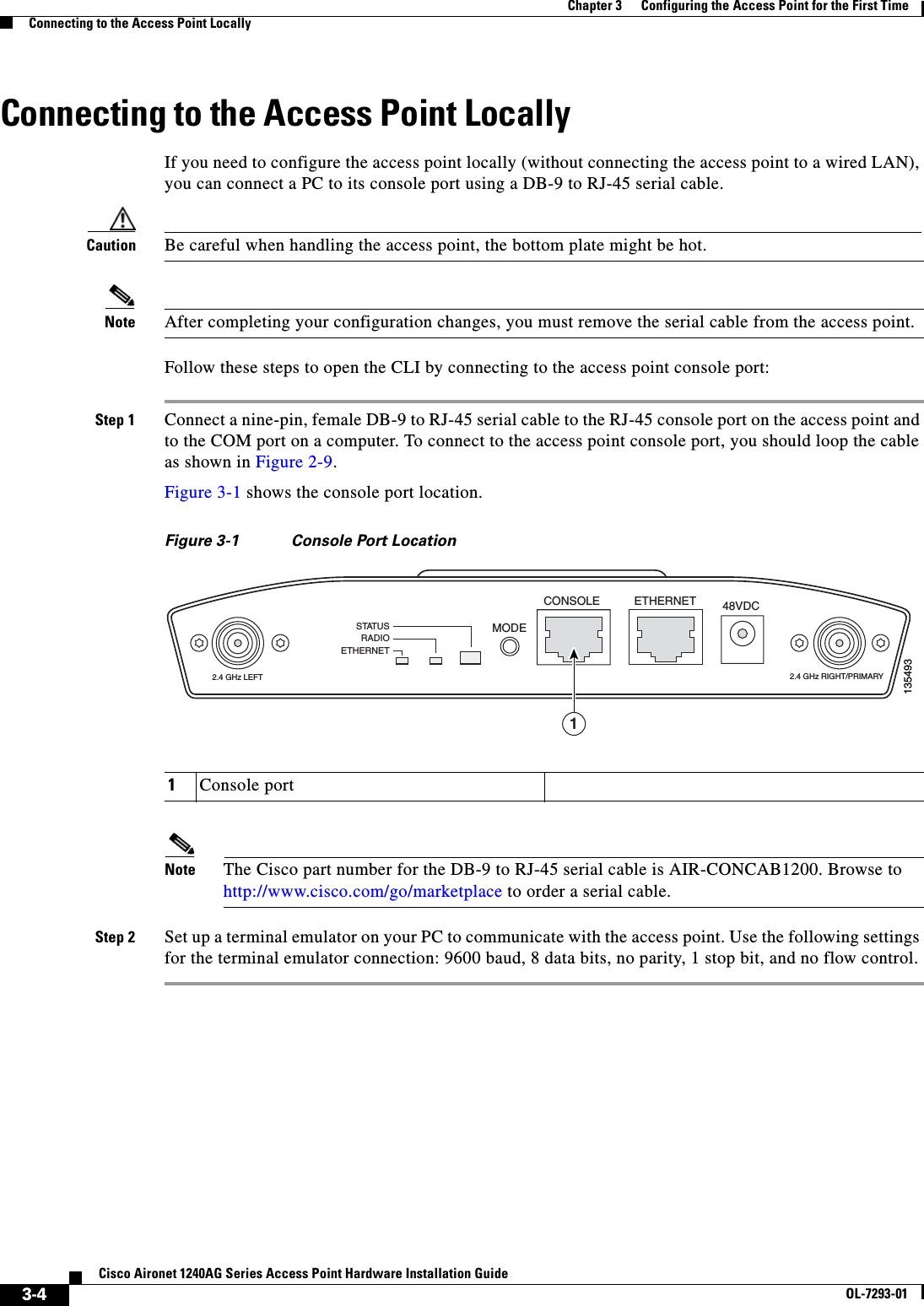
![iiCisco Aironet 1240AG Series Access Point Hardware Installation GuideOL-7293-01PrefaceConventionsChapter 4, “Using the Web-Browser Interface,” describes how to use the web-browser interface to configure the access point.Chapter 5, “Using the Command-Line Interface,” describes how to use the command-line interface (CLI) to configure the access point.Chapter 6, “Troubleshooting,” provides troubleshooting procedures for basic problems with the access point.Appendix A, “Translated Safety Warnings,” provides translations of the safety warnings that appear in this publication.Appendix B, “Declarations of Conformity and Regulatory Information,” provides declarations of conformity and regulatory information for the access point.Appendix C, “Access Point Specifications,” lists technical specifications for the access point.Appendix D, “Channels and Power Levels,” lists the access point radio channels and the maximum power levels supported by the world’s regulatory domains.Appendix E, “Console Cable Pinouts,” identifies the pinouts for the serial console cable that connects to the access point’s serial console port. ConventionsThis publication uses these conventions to convey instructions and information:Command descriptions use these conventions:•Commands and keywords are in boldface text.•Arguments for which you supply values are in italic.•Square brackets ([ ]) mean optional elements.•Braces ({ }) group required choices, and vertical bars ( | ) separate the alternative elements.•Braces and vertical bars within square brackets ([{ | }]) mean a required choice within an optional element.Interactive examples use these conventions:•Terminal sessions and system displays are in screen font.•Information you enter is in boldface screen font.•Nonprinting characters, such as passwords or tabs, are in angle brackets (< >).Notes, cautions, and timesavers use these conventions and symbols:Tip Means the following will help you solve a problem. The tips information might not be troubleshooting or even an action, but could be useful information.Note Means reader take note. Notes contain helpful suggestions or references to materials not contained in this manual.](https://usermanual.wiki/Cisco-Systems/102055/User-Guide-576876-Page-10.png)
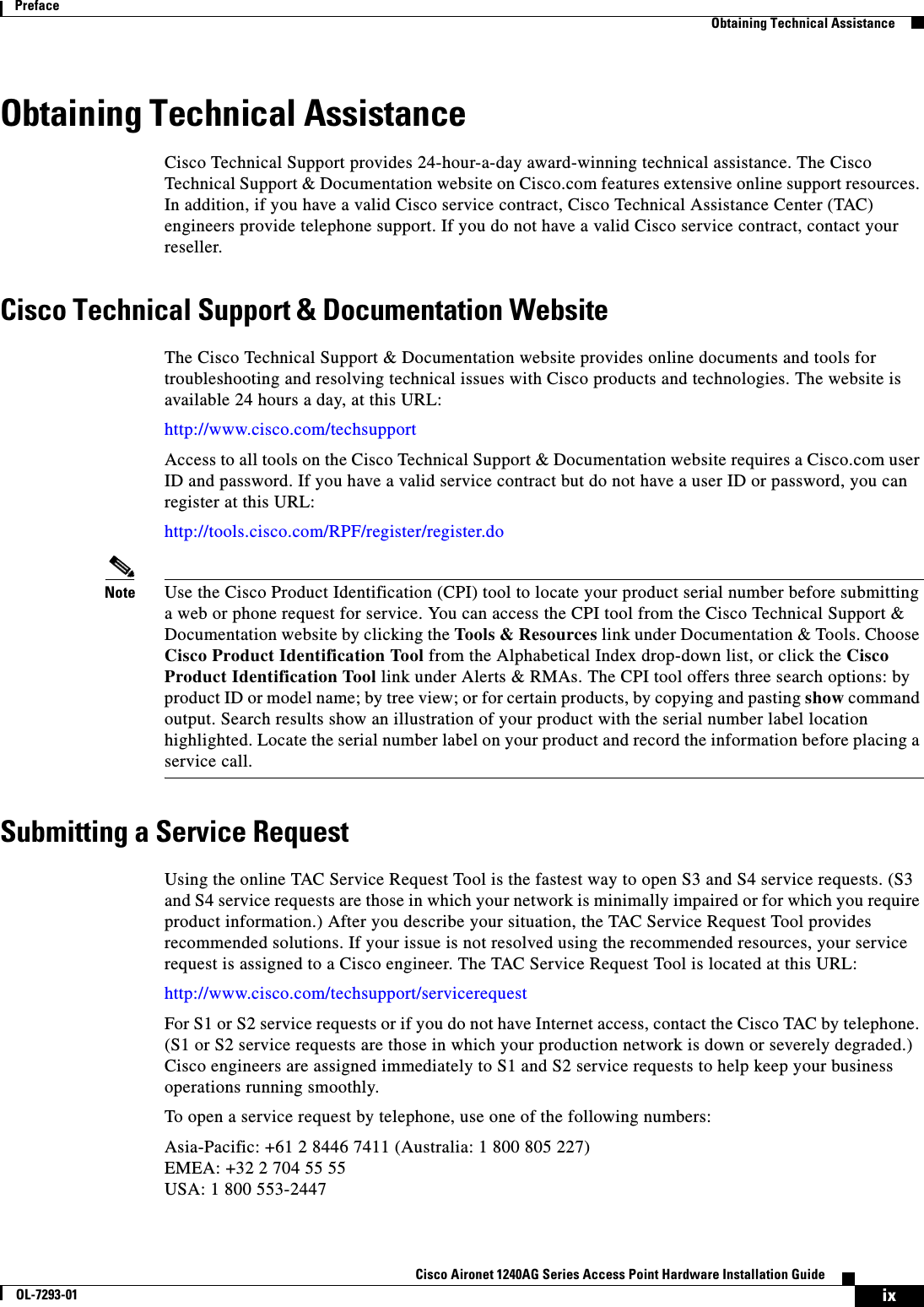
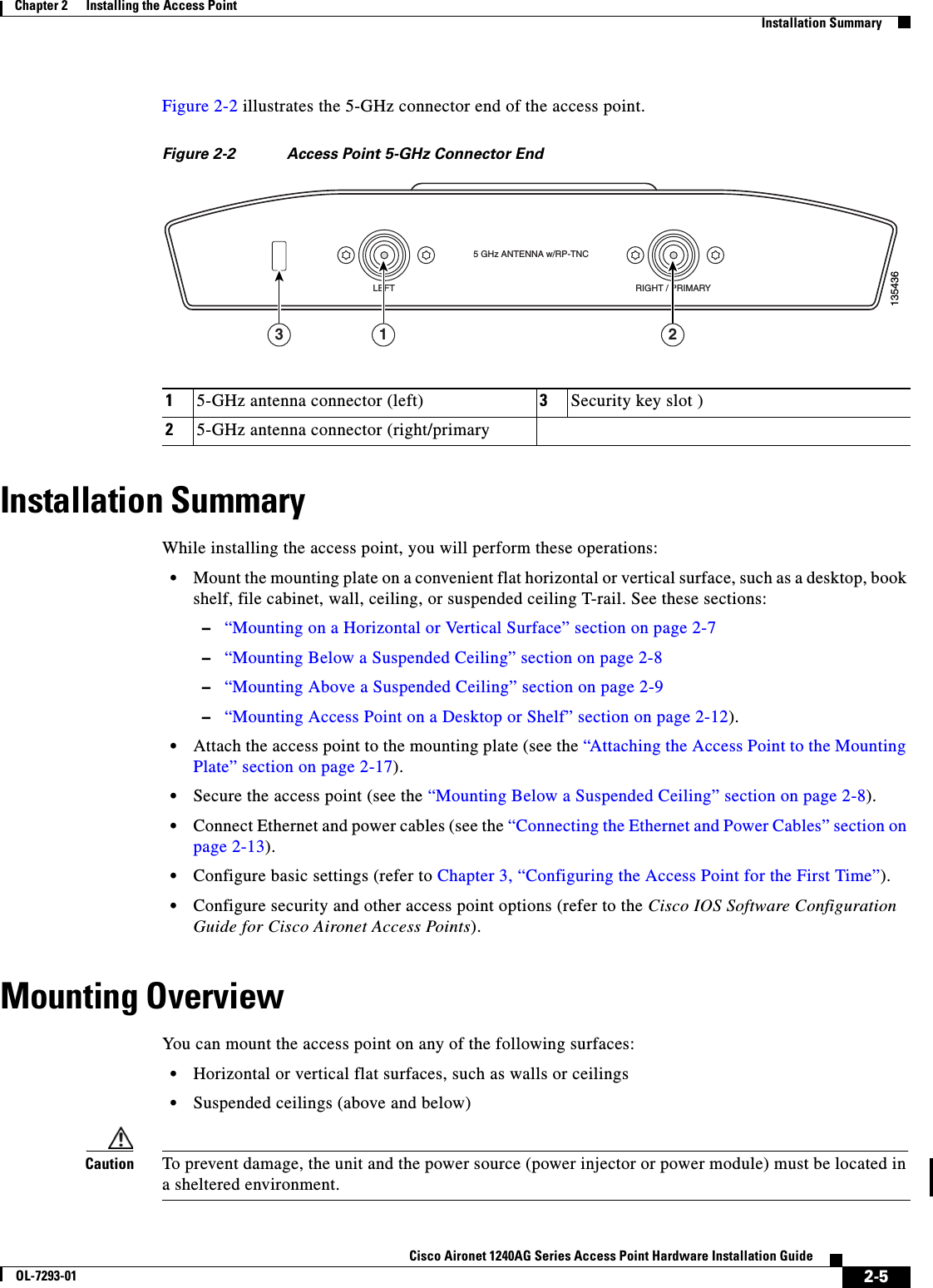
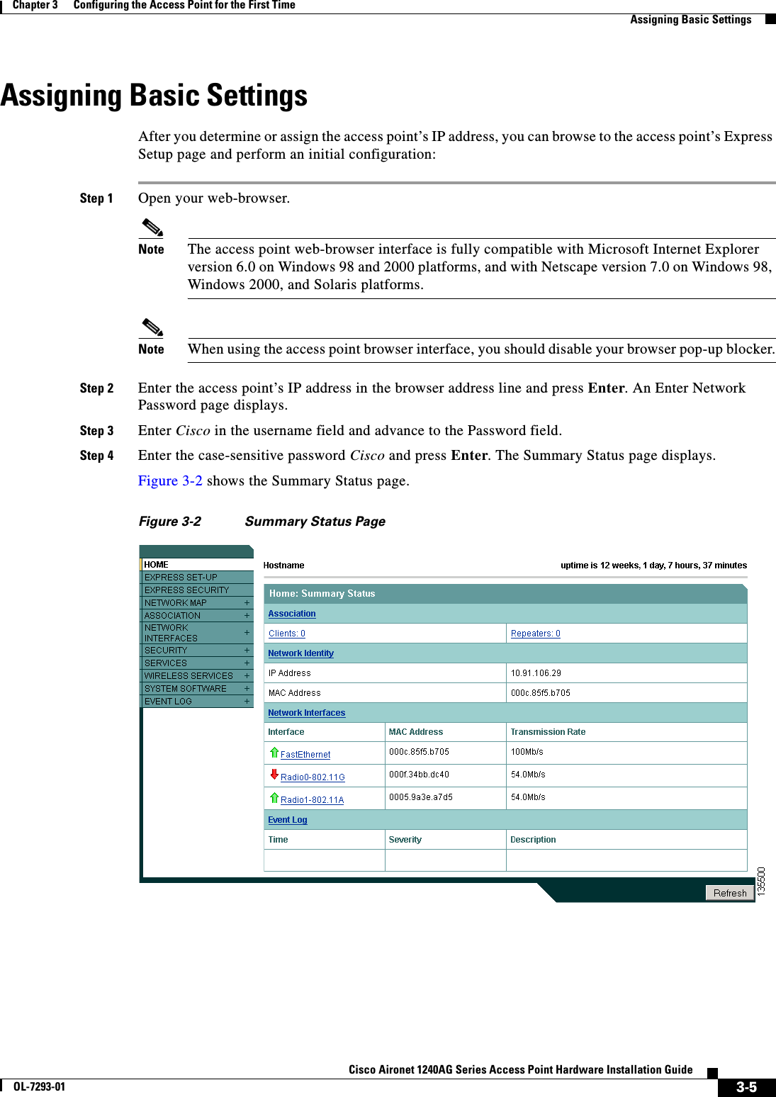
![iiiCisco Aironet 1240AG Series Access Point Hardware Installation GuideOL-7293-01PrefaceConventionsCaution Means reader be careful. In this situation, you might do something that could result equipment damage or loss of data.WarningThis warning symbol means danger. You are in a situation that could cause bodily injury. Before you work on any equipment, be aware of the hazards involved with electrical circuitry and be familiar with standard practices for preventing accidents. (To see translations of the warnings that appear in this publication, refer to the appendix “Translated Safety Warnings.”)WaarschuwingDit waarschuwingssymbool betekent gevaar. U verkeert in een situatie die lichamelijk letsel kan veroorzaken. Voordat u aan enige apparatuur gaat werken, dient u zich bewust te zijn van de bij elektrische schakelingen betrokken risico’s en dient u op de hoogte te zijn van standaard maatregelen om ongelukken te voorkomen. (Voor vertalingen van de waarschuwingen die in deze publicatie verschijnen, kunt u het aanhangsel “Translated Safety Warnings” (Vertalingen van veiligheidsvoorschriften) raadplegen.)VaroitusTämä varoitusmerkki merkitsee vaaraa. Olet tilanteessa, joka voi johtaa ruumiinvammaan. Ennen kuin työskentelet minkään laitteiston parissa, ota selvää sähkökytkentöihin liittyvistä vaaroista ja tavanomaisista onnettomuuksien ehkäisykeinoista. (Tässä julkaisussa esiintyvien varoitusten käännökset löydät liitteestä "Translated Safety Warnings" (käännetyt turvallisuutta koskevat varoitukset).)AttentionCe symbole d’avertissement indique un danger. Vous vous trouvez dans une situation pouvant entraîner des blessures. Avant d’accéder à cet équipement, soyez conscient des dangers posés par les circuits électriques et familiarisez-vous avec les procédures courantes de prévention des accidents. Pour obtenir les traductions des mises en garde figurant dans cette publication, veuillez consulter l’annexe intitulée « Translated Safety Warnings » (Traduction des avis de sécurité).WarnungDieses Warnsymbol bedeutet Gefahr. Sie befinden sich in einer Situation, die zu einer Körperverletzung führen könnte. Bevor Sie mit der Arbeit an irgendeinem Gerät beginnen, seien Sie sich der mit elektrischen Stromkreisen verbundenen Gefahren und der Standardpraktiken zur Vermeidung von Unfällen bewußt. (Übersetzungen der in dieser Veröffentlichung enthaltenen Warnhinweise finden Sie im Anhang mit dem Titel “Translated Safety Warnings” (Übersetzung der Warnhinweise).)AvvertenzaQuesto simbolo di avvertenza indica un pericolo. Si è in una situazione che può causare infortuni. Prima di lavorare su qualsiasi apparecchiatura, occorre conoscere i pericoli relativi ai circuiti elettrici ed essere al corrente delle pratiche standard per la prevenzione di incidenti. La traduzione delle avvertenze riportate in questa pubblicazione si trova nell’appendice, “Translated Safety Warnings” (Traduzione delle avvertenze di sicurezza).AdvarselDette varselsymbolet betyr fare. Du befinner deg i en situasjon som kan føre til personskade. Før du utfører arbeid på utstyr, må du være oppmerksom på de faremomentene som elektriske kretser innebærer, samt gjøre deg kjent med vanlig praksis når det gjelder å unngå ulykker. (Hvis du vil se oversettelser av de advarslene som finnes i denne publikasjonen, kan du se i vedlegget "Translated Safety Warnings" [Oversatte sikkerhetsadvarsler].)](https://usermanual.wiki/Cisco-Systems/102055/User-Guide-576876-Page-11.png)
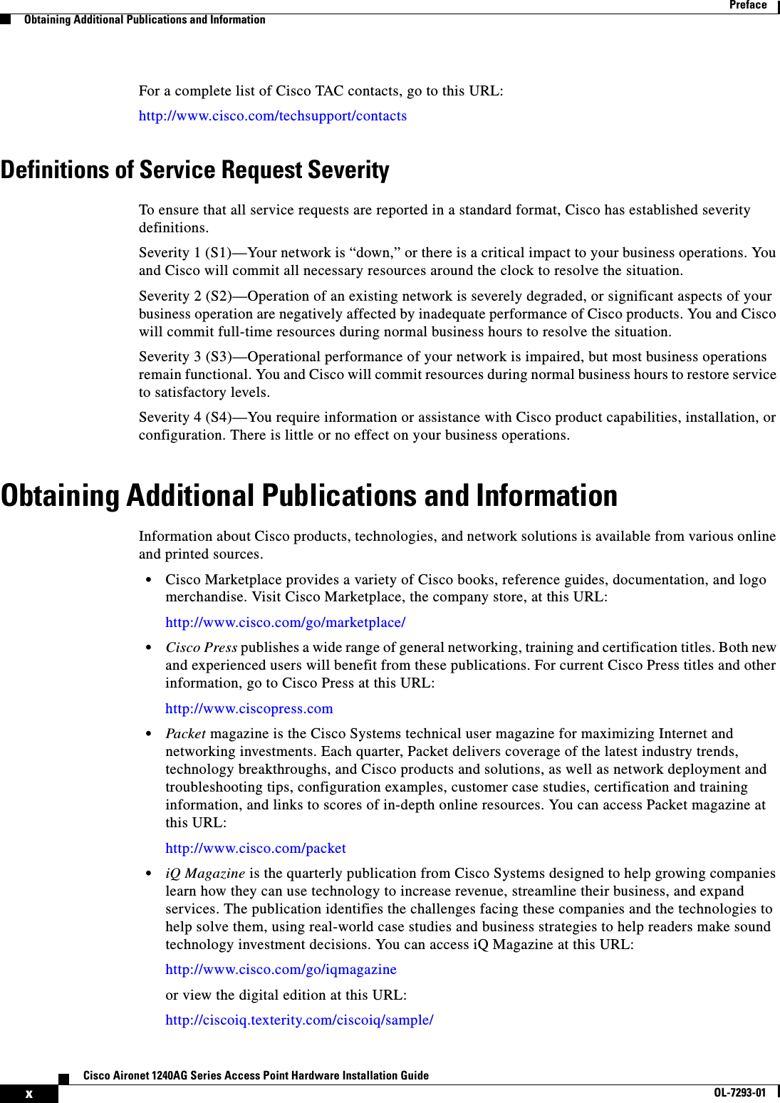
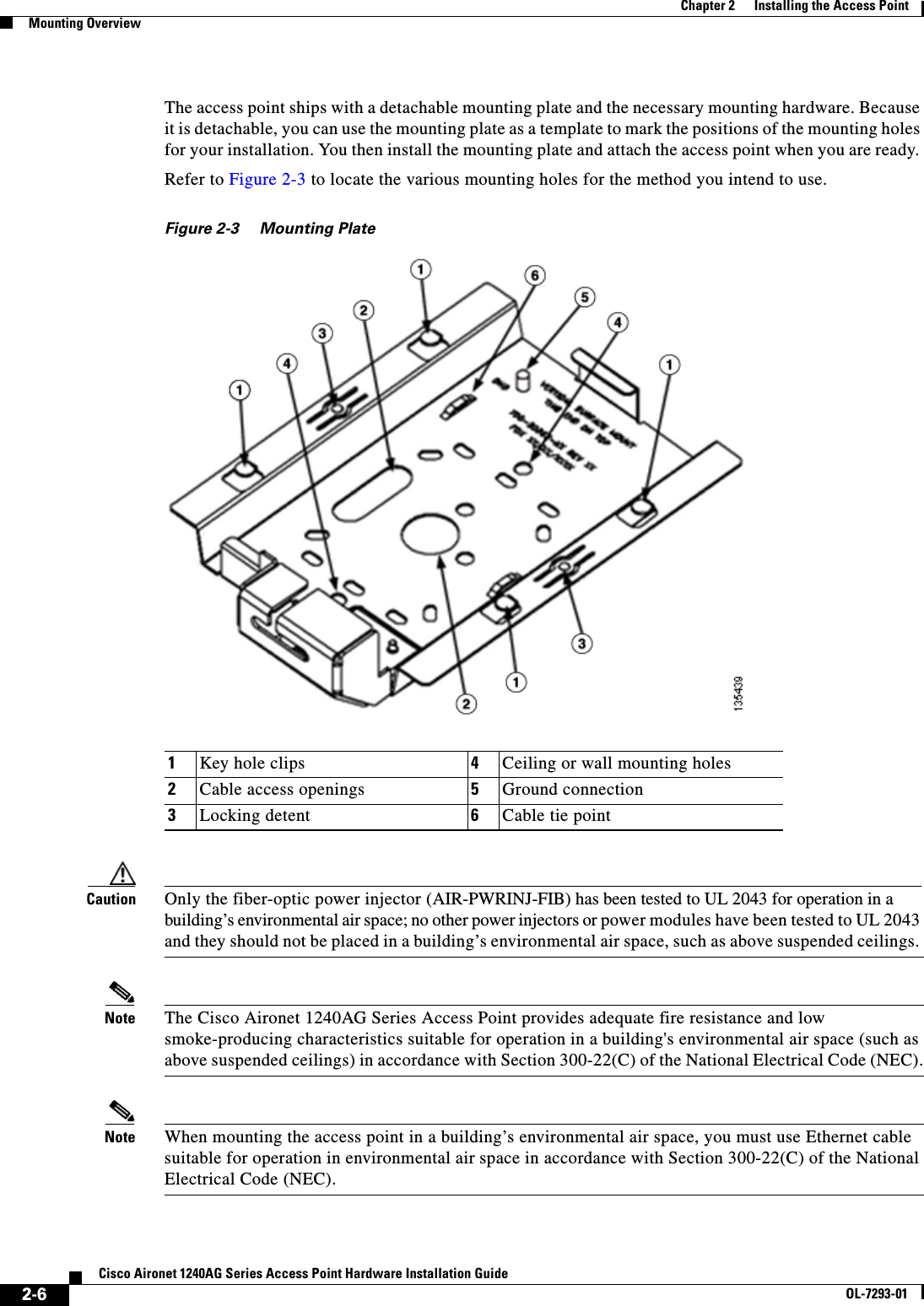
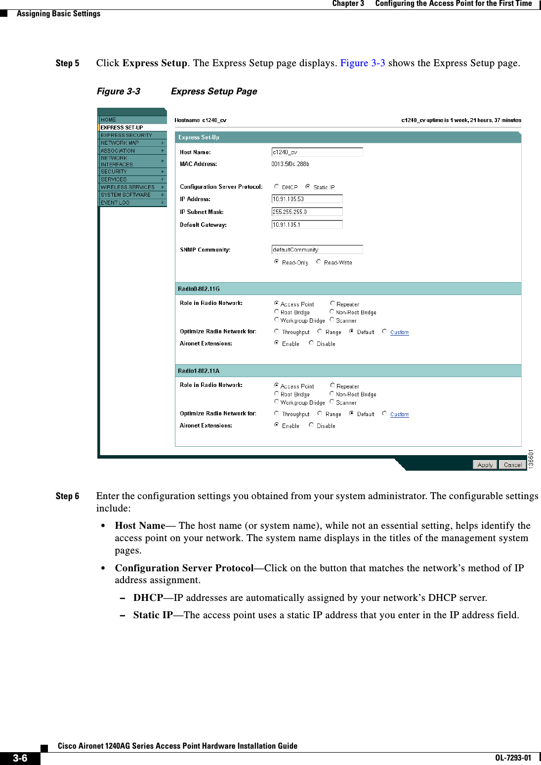
![ivCisco Aironet 1240AG Series Access Point Hardware Installation GuideOL-7293-01PrefaceRelated PublicationsRelated PublicationsThese documents provide complete information about the access point:•Release Notes for Cisco Aironet 1240AG Series Access Point •Cisco IOS Command Reference for Cisco Aironet Access Points and Bridges •Cisco IOS Software Configuration Guide for Cisco Aironet Access PointsClick this link to browse to the Cisco Aironet documentation home page:http://www.cisco.com/en/US/products/hw/wireless/tsd_products_support_category_home.htmlTo browse to the 1240AG series access point documentation, click Cisco Aironet 1240AG Series, which is listed under Wireless LAN Access. Obtaining DocumentationCisco documentation and additional literature are available on Cisco.com. Cisco also provides several ways to obtain technical assistance and other technical resources. These sections explain how to obtain technical information from Cisco Systems.Cisco.comYou can access the most current Cisco documentation at this URL:http://www.cisco.com/techsupportYou can access the Cisco website at this URL:http://www.cisco.comYou can access international Cisco websites at this URL:http://www.cisco.com/public/countries_languages.shtmlAvisoEste símbolo de aviso indica perigo. Encontra-se numa situação que lhe poderá causar danos fisicos. Antes de começar a trabalhar com qualquer equipamento, familiarize-se com os perigos relacionados com circuitos eléctricos, e com quaisquer práticas comuns que possam prevenir possíveis acidentes. (Para ver as traduções dos avisos que constam desta publicação, consulte o apêndice “Translated Safety Warnings” - “Traduções dos Avisos de Segurança”).¡Advertencia!Este símbolo de aviso significa peligro. Existe riesgo para su integridad física. Antes de manipular cualquier equipo, considerar los riesgos que entraña la corriente eléctrica y familiarizarse con los procedimientos estándar de prevención de accidentes. (Para ver traducciones de las advertencias que aparecen en esta publicación, consultar el apéndice titulado “Translated Safety Warnings.”)Varning!Denna varningssymbol signalerar fara. Du befinner dig i en situation som kan leda till personskada. Innan du utför arbete på någon utrustning måste du vara medveten om farorna med elkretsar och känna till vanligt förfarande för att förebygga skador. (Se förklaringar av de varningar som förekommer i denna publikation i appendix "Translated Safety Warnings" [Översatta säkerhetsvarningar].)](https://usermanual.wiki/Cisco-Systems/102055/User-Guide-576876-Page-12.png)
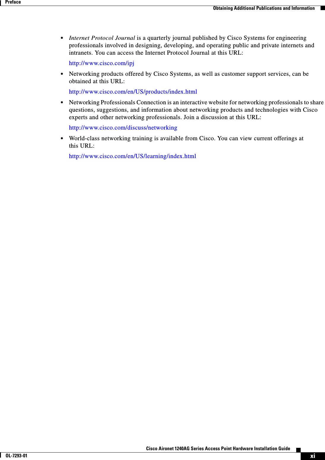
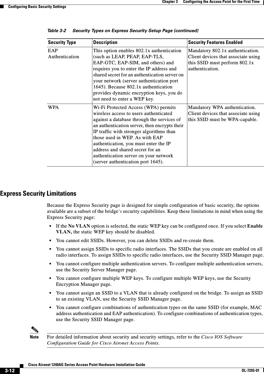
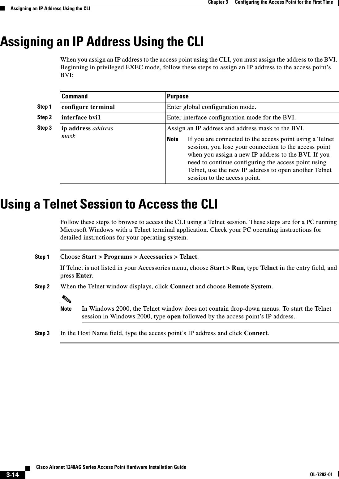
![3-13Cisco Aironet 1240AG Series Access Point Hardware Installation GuideOL-7293-01Chapter 3 Configuring the Access Point for the First TimeFinding the IP Address Using the CLIUsing the Express Security PageFollow these steps to create an SSID using the Express Security page:Step 1 Type the SSID in the SSID entry field. The SSID can contain up to 32 alphanumeric characters.Note These characters are not allowed in the SSID: ", /, ], +, tab, and a trailing space character. Step 2 To broadcast the SSID in the bridge beacon, check the Broadcast SSID in Beacon check box. When you broadcast the SSID, devices that do not specify an SSID can associate to the bridge. This is a useful option for an SSID used by guests or by client devices in a public space. If you do not broadcast the SSID, client devices cannot associate to the bridge unless their SSID matches this SSID. Only one SSID can be included in the bridge beacon.Step 3 (Optional) Check the Enable VLAN ID check box and enter a VLAN number (1 through 4095) to assign the SSID to a VLAN. You cannot assign an SSID to an existing VLAN.Step 4 (Optional) Check the Native VLAN check box to mark the VLAN as the native VLAN. Step 5 Select the security setting for the SSID. The settings are listed in order of robustness, from No Security to WPA, which is the most secure setting. •If you select Static WEP Key, choose the key number and encryption key size and enter the encryption key (10 hexidecimal characters for 40-bit keys or 26 hexidecimal characters for 128-bit keys).•If you select EAP Authentication or WPA, enter the IP address and shared secret for the authentication server on your network.Note If you do not use VLANs on your wireless LAN, the security options that you can assign to multiple SSIDs are limited. Refer to the Cisco IOS Software Configuration Guide for Cisco Aironet Access Points for VLAN details.Step 6 Click Apply. The SSID appears in the SSID table at the bottom of the page.Finding the IP Address Using the CLIWhen you connect the access point to the wired LAN, the access point links to the network using a bridge virtual interface (BVI) that it creates automatically. Instead of tracking separate IP addresses for the access point’s Ethernet and radio ports, the network uses the BVI.To find the IP address of your access point using the console port, you can use the Cisco IOS CLI show ip interface brief bvi1 from the privileged EXEC mode. For additional information on the CLI, refer to the“Using the Command-Line Interface” section on page 5-1.](https://usermanual.wiki/Cisco-Systems/102055/User-Guide-576876-Page-65.png)

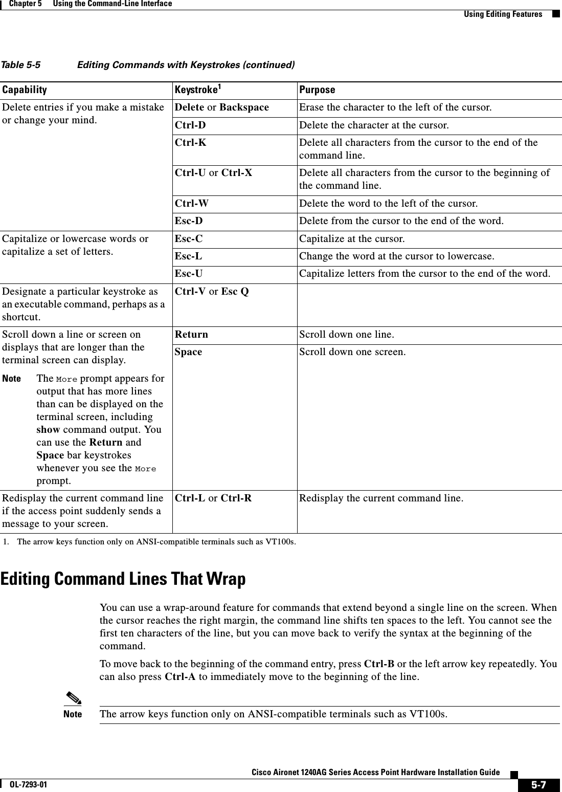
![5-5Cisco Aironet 1240AG Series Access Point Hardware Installation GuideOL-7293-01Chapter 5 Using the Command-Line InterfaceUsing Command HistoryChanging the Command History Buffer SizeBy default, the access point records ten command lines in its history buffer. Beginning in privileged EXEC mode, enter this command to change the number of command lines that the access point records during the current terminal session: ap# terminal history [size number-of-lines]The range is from 0 to 256.Beginning in line configuration mode, enter this command to configure the number of command lines the access point records for all sessions on a particular line:ap(config-line)# history [size number-of-lines]The range is from 0 to 256.Recalling CommandsTo recall commands from the history buffer, perform one of the actions listed in Table 5-4:Disabling the Command History FeatureThe command history feature is automatically enabled. To disable the feature during the current terminal session, enter the terminal no history privileged EXEC command. To disable command history for the line, enter the no history line configuration command.Table 5-4 Recalling CommandsAction11. The arrow keys function only on ANSI-compatible terminals such as VT100s.ResultPress Ctrl-P or the up arrow key. Recall commands in the history buffer, beginning with the most recent command. Repeat the key sequence to recall successively older commands.Press Ctrl-N or the down arrow key. Return to more recent commands in the history buffer after recalling commands with Ctrl-P or the up arrow key. Repeat the key sequence to recall successively more recent commands. show history While in privileged EXEC mode, list the last several commands that you just entered. The number of commands that are displayed is determined by the setting of the terminal history global configuration command and history line configuration command.](https://usermanual.wiki/Cisco-Systems/102055/User-Guide-576876-Page-77.png)
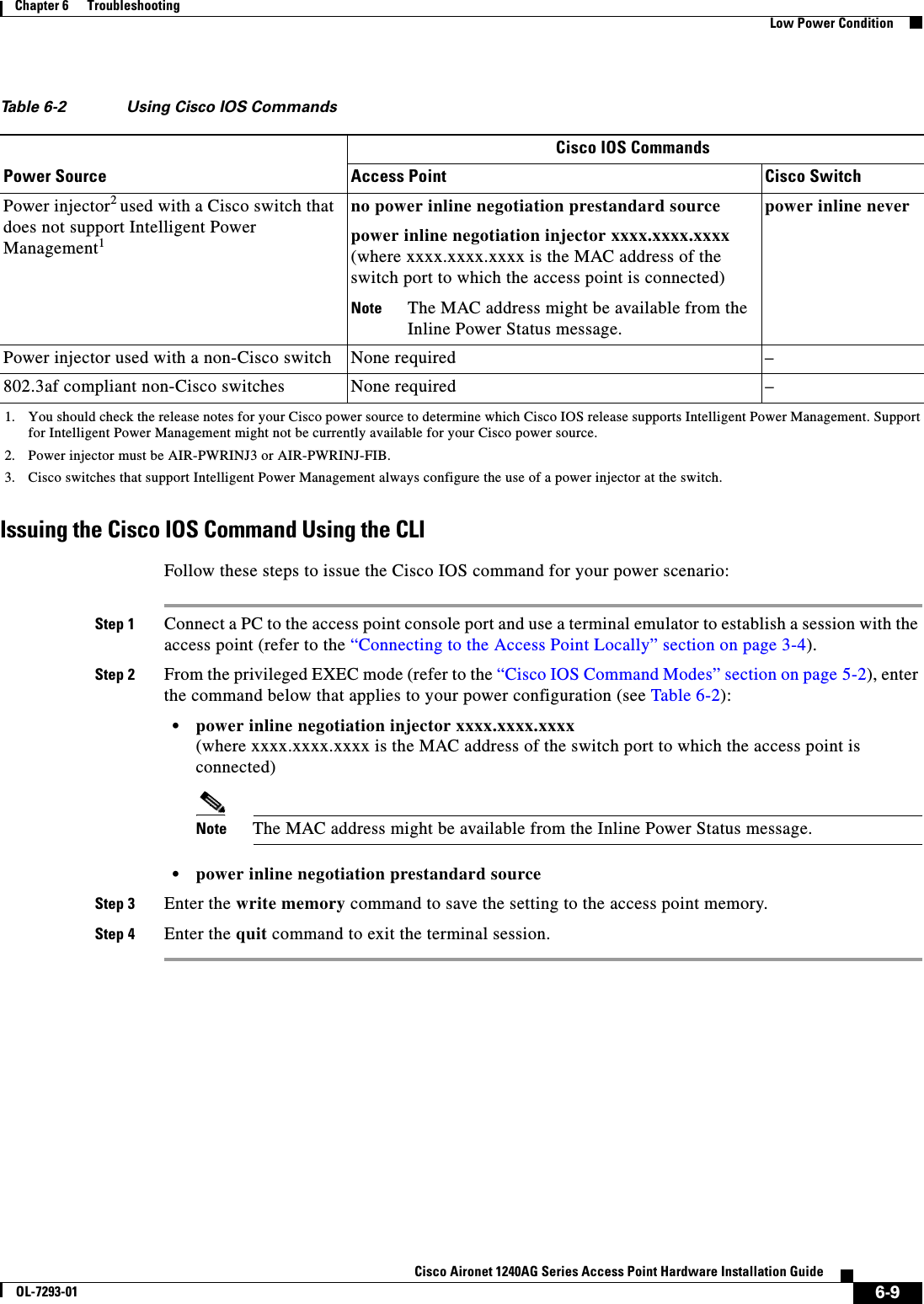
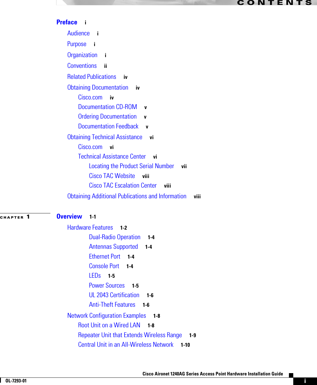
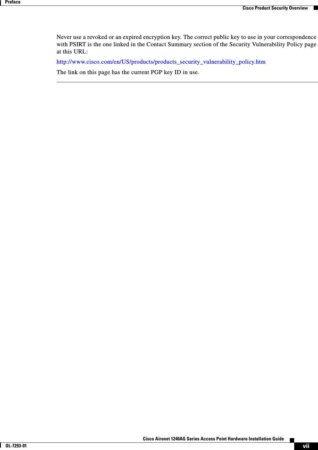
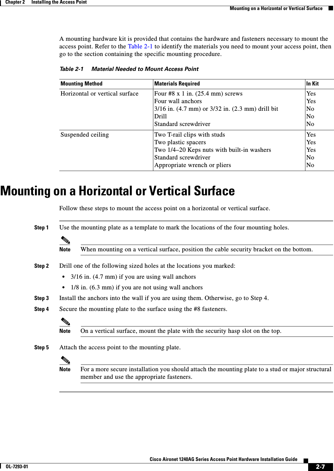
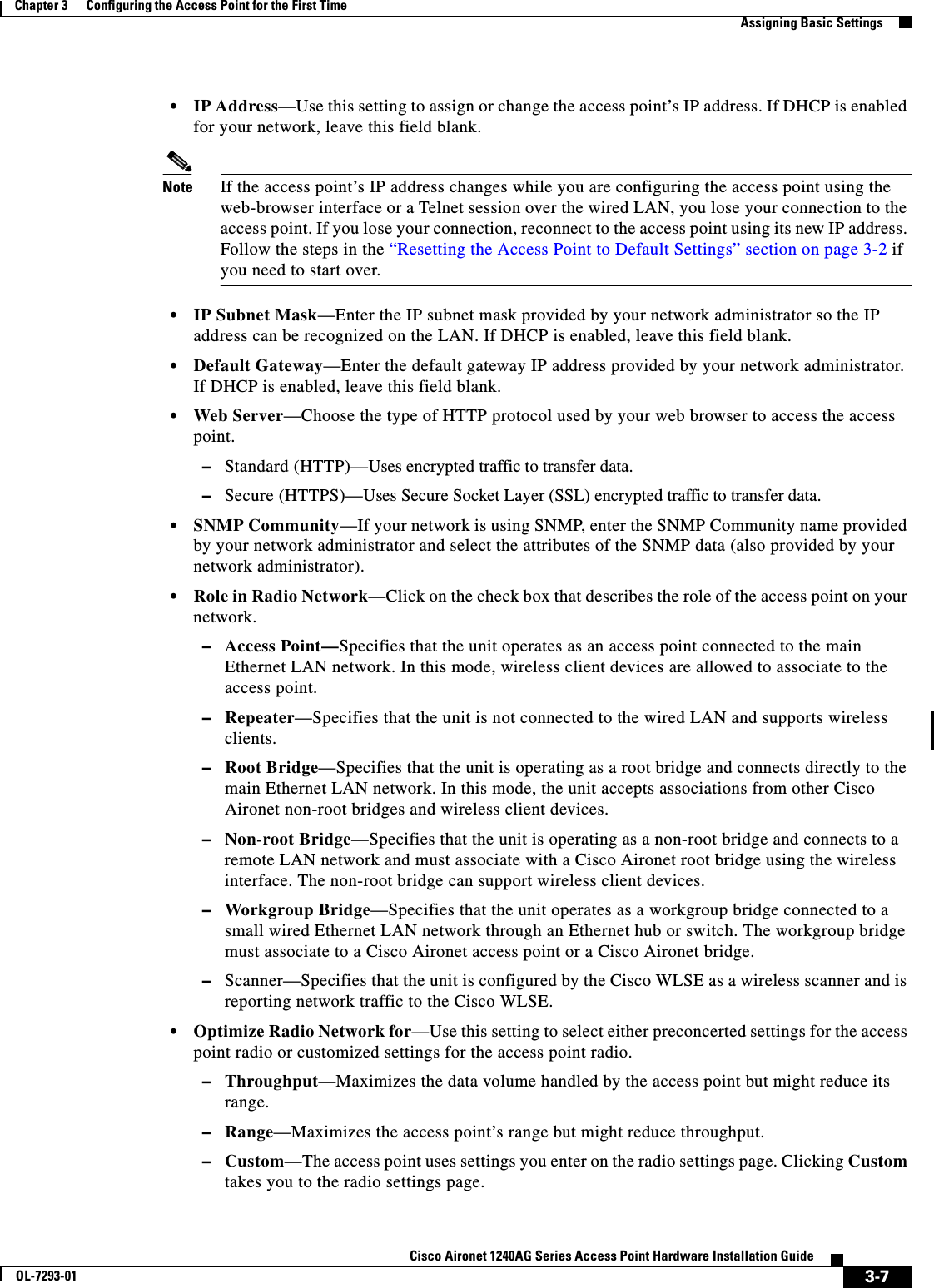
![6-8Cisco Aironet 1240AG Series Access Point Hardware Installation GuideOL-7293-01Chapter 6 TroubleshootingLow Power ConditionThe< platform name> indicates the Cisco platform detected by the access point. The <xxxx.xxxx.xxxx> indicates the MAC address of the switch port.Note You need to upgrade the software on the Cisco switch to support Intelligent Power Management or configure the access point for pre-standard compatibility.Configuring Power Using the CLIIntelligent Power Management support is dependent on the version of software resident in the Cisco switch that is providing power to the access point. Each Cisco switch should be upgraded to support Intelligent Power Management. Until the software is upgraded, you can configure the access point to operate with older switch software using the following Cisco IOS CLI command:[no] power inline negotiation {prestandard source | injector H.H.H}(where H.H.H is the MAC address of the switch port to which the access point is connected)You can use this Cisco IOS CLI command to inform the access point of the following:•The Cisco switch does not support Intelligent Power Management but should be able to supply sufficient power.•A power injector is being used to supply sufficient power and the Cisco switch does not support Intelligent Power Management. Refer to Table 6-2 for information on when to use this special Cisco IOS command and the corresponding Cisco switch power command.Caution If the access point receives power through PoE, the output current of the power sourcing equipment (PSE) cannot exceed 400 mA per port. The power source must comply with IEEE802.3af or IEC60950 for limited power sources.Note After completing your configuration changes, you must remove the serial console cable from the access point.Table 6-2 Using Cisco IOS CommandsPower SourceCisco IOS CommandsAccess Point Cisco SwitchAC power module None required power inline neverCisco switch that supports Intelligent Power Management1no power inline negotiation prestandard sourceno power inline negotiation injectorpower inline auto Cisco switch that does not support Intelligent Power Management1power inline negotiation prestandard sourceno power inline negotiation injectorpower inline autoPower injector2 used with a Cisco switch that supports Intelligent Power Management1no power inline negotiation prestandard sourceno power inline negotiation injectorpower inline never3](https://usermanual.wiki/Cisco-Systems/102055/User-Guide-576876-Page-90.png)