Cisco Systems 102060 802.11g Radio Module User Manual 125h tl
Cisco Systems Inc 802.11g Radio Module 125h tl
Users Manual

CISCO CONFIDENTIAL - Draft 1
Corporate Headquarters
Cisco Systems, Inc.
170 West Tasman Drive
San Jose, CA 95134-1706
USA
http://www.cisco.com
Tel: 408 526-4000
800 553-NETS (6387)
Fax: 408 526-4100
Cisco Aironet 1250AG Series Access Point
Hardware Installation Guide
June 2006
Text Part Number: OL-8247-01

CISCO CONFIDENTIAL - Draft 1
THE SPECIFICATIONS AND INFORMATION REGARDING THE PRODUCTS IN THIS MANUAL ARE SUBJECT TO CHANGE WITHOUT NOTICE. ALL
STATEMENTS, INFORMATION, AND RECOMMENDATIONS IN THIS MANUAL ARE BELIEVED TO BE ACCURATE BUT ARE PRESENTED WITHOUT
WARRANTY OF ANY KIND, EXPRESS OR IMPLIED. USERS MUST TAKE FULL RESPONSIBILITY FOR THEIR APPLICATION OF ANY PRODUCTS.
THE SOFTWARE LICENSE AND LIMITED WARRANTY FOR THE ACCOMPANYING PRODUCT ARE SET FORTH IN THE INFORMATION PACKET THAT
SHIPPED WITH THE PRODUCT AND ARE INCORPORATED HEREIN BY THIS REFERENCE. IF YOU ARE UNABLE TO LOCATE THE SOFTWARE LICENSE
OR LIMITED WARRANTY, CONTACT YOUR CISCO REPRESENTATIVE FOR A COPY.
The following information is for FCC compliance of Class A devices: This equipment has been tested and found to comply with the limits for a Class A digital device, pursuant
to part 15 of the FCC rules. These limits are designed to provide reasonable protection against harmful interference when the equipment is operated in a commercial
environment. This equipment generates, uses, and can radiate radio-frequency energy and, if not installed and used in accordance with the instruction manual, may cause
harmful interference to radio communications. Operation of this equipment in a residential area is likely to cause harmful interference, in which case users will be required
to correct the interference at their own expense.
The following information is for FCC compliance of Class B devices: The equipment described in this manual generates and may radiate radio-frequency energy. If it is not
installed in accordance with Cisco’s installation instructions, it may cause interference with radio and television reception. This equipment has been tested and found to
comply with the limits for a Class B digital device in accordance with the specifications in part 15 of the FCC rules. These specifications are designed to provide reasonable
protection against such interference in a residential installation. However, there is no guarantee that interference will not occur in a particular installation.
Modifying the equipment without Cisco’s written authorization may result in the equipment no longer complying with FCC requirements for Class A or Class B digital
devices. In that event, your right to use the equipment may be limited by FCC regulations, and you may be required to correct any interference to radio or television
communications at your own expense.
You can determine whether your equipment is causing interference by turning it off. If the interference stops, it was probably caused by the Cisco equipment or one of its
peripheral devices. If the equipment causes interference to radio or television reception, try to correct the interference by using one or more of the following measures:
• Turn the television or radio antenna until the interference stops.
• Move the equipment to one side or the other of the television or radio.
• Move the equipment farther away from the television or radio.
• Plug the equipment into an outlet that is on a different circuit from the television or radio. (That is, make certain the equipment and the television or radio are on circuits
controlled by different circuit breakers or fuses.)
Modifications to this product not authorized by Cisco Systems, Inc. could void the FCC approval and negate your authority to operate the product.
The Cisco implementation of TCP header compression is an adaptation of a program developed by the University of California, Berkeley (UCB) as part of UCB’s public
domain version of the UNIX operating system. All rights reserved. Copyright © 1981, Regents of the University of California.
NOTWITHSTANDING ANY OTHER WARRANTY HEREIN, ALL DOCUMENT FILES AND SOFTWARE OF THESE SUPPLIERS ARE PROVIDED “AS IS” WITH
ALL FAULTS. CISCO AND THE ABOVE-NAMED SUPPLIERS DISCLAIM ALL WARRANTIES, EXPRESSED OR IMPLIED, INCLUDING, WITHOUT
LIMITATION, THOSE OF MERCHANTABILITY, FITNESS FOR A PARTICULAR PURPOSE AND NONINFRINGEMENT OR ARISING FROM A COURSE OF
DEALING, USAGE, OR TRADE PRACTICE.
IN NO EVENT SHALL CISCO OR ITS SUPPLIERS BE LIABLE FOR ANY INDIRECT, SPECIAL, CONSEQUENTIAL, OR INCIDENTAL DAMAGES, INCLUDING,
WITHOUT LIMITATION, LOST PROFITS OR LOSS OR DAMAGE TO DATA ARISING OUT OF THE USE OR INABILITY TO USE THIS MANUAL, EVEN IF CISCO
OR ITS SUPPLIERS HAVE BEEN ADVISED OF THE POSSIBILITY OF SUCH DAMAGES.
Cisco Aironet 1250AG Series Access Point Hardware Installation Guide
© 2006 Cisco Systems, Inc. All rights reserved.
CCSP, CCVP, the Cisco Square Bridge logo, Follow Me Browsing, and StackWise are trademarks of Cisco Systems, Inc.; Changing the Way We Work, Live, Play, and Learn, and
iQuick Study are service marks of Cisco Systems, Inc.; and Access Registrar, Aironet, BPX, Catalyst, CCDA, CCDP, CCIE, CCIP, CCNA, CCNP, Cisco, the Cisco Certified
Internetwork Expert logo, Cisco IOS, Cisco Press, Cisco Systems, Cisco Systems Capital, the Cisco Systems logo, Cisco Unity, Enterprise/Solver, EtherChannel, EtherFast,
EtherSwitch, Fast Step, FormShare, GigaDrive, GigaStack, HomeLink, Internet Quotient, IOS, IP/TV, iQ Expertise, the iQ logo, iQ Net Readiness Scorecard, LightStream,
Linksys, MeetingPlace, MGX, the Networkers logo, Networking Academy, Network Registrar, Packet , PIX, Post-Routing, Pre-Routing, ProConnect, RateMUX, ScriptShare,
SlideCast, SMARTnet, The Fastest Way to Increase Your Internet Quotient, and TransPath are registered trademarks of Cisco Systems, Inc. and/or its affiliates in the United States
and certain other countries.
All other trademarks mentioned in this document or Website are the property of their respective owners. The use of the word partner does not imply a partnership relationship
between Cisco and any other company. (0601R)

CHAPTER
CISCO CONFIDENTIAL - Draft 1
1-1
Cisco Aironet 1250AG Series Access Point Hardware Installation Guide
OL-8247-01
1
Overview
Cisco Aironet 1250AG Series Access Points combine mobility, flexibility, and modularity with the
enterprise-class features required by networking professionals. With a management system based on
Cisco IOS software software, the 1250AG series access point is a Wi-Fi certified, wireless LAN
transceiver.
The access point supports two radio modules: a 2.4-GHz radio (IEEE 802.11b/g) and a 5-GHz radio
(IEEE 802.11a). The modular design enables support for a future IEEE802.11n radio module once the
standard is ratified. This modularity helps customers future proof their access point investments.
You can configure the radios separately, using different settings on each. The access point connects
wireless and wired networks or is the center point of a stand-alone wireless network. In large
installations, wireless users within radio range of an access point can roam throughout a facility while
maintaining seamless, uninterrupted access to the network.
You can configure and monitor the access point using the command-line interface (CLI), the
browser-based management system, Simple Network Management Protocol (SNMP), or Cisco
Structured Wireless-Aware Network (SWAN).
This chapter provides information on the following topics:
•Hardware Features, page 1-2
•Network Configuration Examples, page 1-7

CISCO CONFIDENTIAL - Draft 1
1-2
Cisco Aironet 1250AG Series Access Point Hardware Installation Guide
OL-8247-01
Chapter 1 Overview
Hardware Features
Hardware Features
Key hardware features of the access point include:
•Dual-radio operation with radio modules (see page 1-4)
•Ethernet port (see page 1-5)
•Console port (see page 1-5)
•LEDs, (see page 1-5)
•Multiple power sources (see page 1-5)
•UL 2043 certification (see page 1-6)
•Anti-theft features (see page 1-6)
Refer to Appendix C, “Access Point Specifications,” for a list of access point specifications.
Figure 1-2 shows the access point with two radio modules.
Figure 1-1 Access Point with 802.11b/g and 802.11a Radio Modules

CISCO CONFIDENTIAL - Draft 1
1-3
Cisco Aironet 1250AG Series Access Point Hardware Installation Guide
OL-8247-01
Chapter 1 Overview
Hardware Features
Figure 1-2 illustrates the 2.4-GHz radio module.
Figure 1-2 2.4 GHz Radio Module
Figure 1-3 illustrates the 5-GHz radio module.
Figure 1-3 5-GHz Radio Module
12.4-GHz antenna connector (left) 3
22.4-GHz antenna connector (right/primary) 5
15-GHz antenna connector (left) 3
25-GHz antenna connector (right/primary)
CISCO CONFIDENTIAL - Draft 1
1-4
Cisco Aironet 1250AG Series Access Point Hardware Installation Guide
OL-8247-01
Chapter 1 Overview
Hardware Features
Single or Dual-Radio Operation
The access point supports single or simultaneous dual radio operation using 2.4-GHz 802.11b/g radio
and 5-GHz 802.11a radio modules. Each radio uses dual-diversity integrated antennas. A blank module
is supported for single radio access point configurations.
The access point supports upgrading of a radio module with a 802.11n radio module (future availability).
The 802.11n radio module will be available when the standard is ratified.
The 5-GHz radio incorporates an Unlicensed National Information Infrastructure (UNII) radio
transceiver operating in the UNII 5-GHz frequency bands. The 802.11g radio is called Radio0 and the
802.11a radio is called Radio1.
Note In Cisco IOS Release 12.3(8)JA and later, the access point radios are disabled by default, and there is no
default SSID. You must create an SSID and enable the radios before the access point allows wireless
associations from other devices.
Antennas Supported
Table 1-1 lists the supported access point antennas.
Caution The access point, the antennas, and the power source (power injector or power module) must be located
in an indoor environment.
Table 1-1 Supported Antennas
2.4-GHz Antennas
Gain
(dBi) 5-GHz Antennas
Gain
(dBi)
AIR-ANT5959 diversity ceiling omnidirectional 2 AIR-ANT5135D-R articulated omnidirectional 3.5
AIR-ANT4941 articulated dipole 2.2 AIR-ANT5145V-R diversityceiling omnidirectional 4.5
AIR-ANT1728 ceiling omnidirectional 5.2 AIR-ANT5160V-R omnidirectional 6
AIR-ANT2506 mast mount omnidirectional 5.2 AIR-ANT5170P-R diversity wall patch directional 7
AIR-ANT3213 diversity pillar omnidirectional 5.2 AIR-ANT5195P-R wall patch directional 9.5
AIR-ANT1729 wall patch directional 6
AIR-ANT2460P-R patch directional 6
AIR-ANT2465P-R diversity patch directional 6.5
AIR-ANT2012 diversity patch directional 6.5
AIR-ANT3549 patch directional 9
AIR-ANT2490P-R patch directional 9
AIR-ANT2410Y-R yagi directional 10

CISCO CONFIDENTIAL - Draft 1
1-5
Cisco Aironet 1250AG Series Access Point Hardware Installation Guide
OL-8247-01
Chapter 1 Overview
Hardware Features
Ethernet Port
The auto-sensing Ethernet port (see Figure TBD ) accepts an RJ-45 connector, linking the access point
to your 10BASE-T, 100BASE-T, or 1000BASE-T Ethernet LAN. The access point can receive power
through the Ethernet cable from a power injector, switch, or power patch panel. The Ethernet MAC
address is printed on the label on the back of the access point (refer to the “Locating the Product Serial
Number” section on page -viii).
Console Port
The serial console port provides access to the access point’s command-line interface (CLI) using a
terminal emulator program. The port is located on the end of the unit (see Figure 1-2). Use an RJ-45 to
DB-9 serial cable to connect your computer’s COM port to the access point’s serial console port. (Refer
to Appendix E, “Console Cable Pinouts,” for a description of the console port pinouts.) Assign the
following port settings to a terminal emulator to open the management system pages: 9600 baud, 8 data
bits, no parity, 1 stop bit, and no flow control.
Note After completing your configuration changes, you must remove the serial cable from the access point.
LEDs
The access point has three LEDs (see Figure 1-2) to indicate Ethernet activity, radio activity, and status
indications (refer to the “Checking the Access Point LEDs” section on page 6-2 for additional
information).
•The Status LED provides general operating status and error indications.
•The Ethernet LED signals Ethernet traffic on the wired Ethernet LAN and provides Ethernet error
indications.
•The Radio LED signals that wireless packets are being transmitted or received over the radio
interface and provides error indications.
Power Sources
The access point can receive power from an external power module or from inline power using the
Ethernet cable. The access point supports the IEEE 802.3af inline power standard and Cisco CDP Power
Negotiation. Using inline power, you do not need to run a power cord to the access point because power
is supplied over the Ethernet cable.
Warning
This product must be connected to a Power over Ethernet (PoE) IEEE 802.3af compliant power source
or an IEC60950 compliant limited power source.
Statement 353
The access point supports the following power sources:
•Power module
•Inline power:
–
Cisco Aironet 1250 Series Power Injector ( (AIR-PWRINJ3 or AIR-PWRINJ-FIB)
–
An inline power capable switch, such as the Cisco Catalyst 3550 PWR XL, 3560-48PS,
3570-48PS, 4500 with 802.3AF PoE module, or the 6500 with 802.3AF PoE module
CISCO CONFIDENTIAL - Draft 1
1-6
Cisco Aironet 1250AG Series Access Point Hardware Installation Guide
OL-8247-01
Chapter 1 Overview
Hardware Features
–
Other inline power switches supporting the IEEE 802.3af inline power standard
Note Some switches and patch panels might not provide enough power to operate the access point with both
2.4-GHz and 5-GHz radios. At power-up, if the access point is unable to determine that the power source
can supply sufficient power, the access point automatically deactivates both radios to prevent an
over-current condition. The access point also activates a Status LED low power error indication and
creates an error log entry (refer to the “Checking the Access Point LEDs” section on page 6-2 and the
“Low Power Condition” section on page 6-5).
UL 2043 Certification
The access point has adequate fire resistance and low smoke-producing characteristics suitable for
operation in a building's environmental air space, such as above suspended ceilings, in accordance with
Section 300-22(c) of the NEC, and with Sections 2-128, 12-010(3) and 12-100 of the Canadian
Electrical Code, Part 1, C22.1.
Caution Only the fiber-optic power injector (AIR-PWRINJ-FIB) has been tested to UL 2043 for operation in a
building’s environmental air space; the AIR-PWRINJ3 power injector and the power module are not
tested to UL 2043 and should not be placed in a building’s environmental air space, such as above
suspended ceilings.
Anti-Theft Features
TBD
CISCO CONFIDENTIAL - Draft 1
1-7
Cisco Aironet 1250AG Series Access Point Hardware Installation Guide
OL-8247-01
Chapter 1 Overview
Network Configuration Examples
Network Configuration Examples
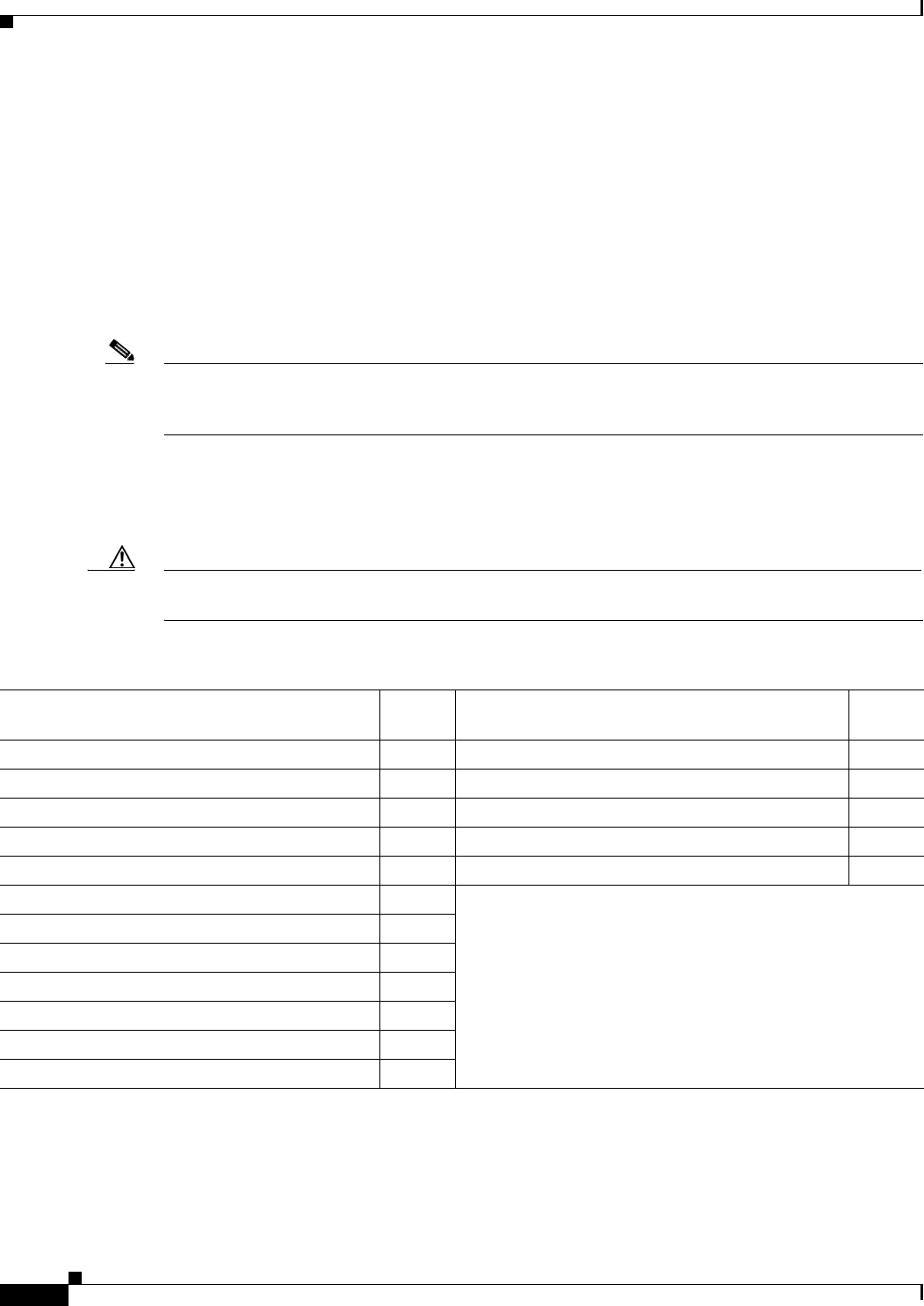
This section describes the access point’s role in three common wireless network configurations. The
access point’s default configuration is as a root unit connected to a wired LAN or as the central unit in
an all-wireless network. The repeater role requires a specific configuration.
Root Unit on a Wired LAN
An access point connected directly to a wired LAN provides a connection point for wireless users. If
more than one access point is connected to the LAN, users can roam from one area of a facility to another
without losing their connection to the network. Figure 1-4 shows access points acting as root units on a
wired LAN.
Figure 1-4 Access Points as Root Units on a Wired LAN
Access point
Access point
135445
CISCO CONFIDENTIAL - Draft 1
1-8
Cisco Aironet 1250AG Series Access Point Hardware Installation Guide
OL-8247-01
Chapter 1 Overview
Network Configuration Examples
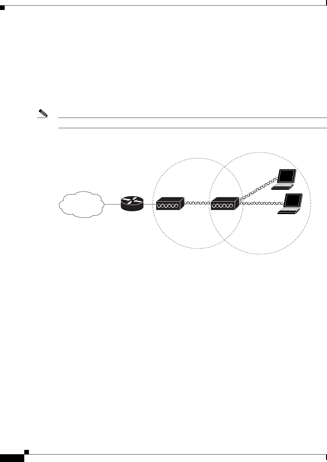
Repeater Unit that Extends Wireless Range
An access point can be configured as a stand-alone repeater to extend the range of your infrastructure or
to overcome an obstacle that blocks radio communication. The repeater forwards traffic between
wireless users and the wired LAN by sending packets to either another repeater or to an access point
connected to the wired LAN. The data is sent through the route that provides the best performance for
the client. Figure 1-5 shows an access point acting as a repeater. Consult the Cisco IOS Software
Configuration Guide for Cisco Aironet Access Points for instructions on setting up an access point as a
repeater.
Note Non-Cisco client devices might have difficulty communicating with repeater access points.
Figure 1-5 Access Point as Repeater
Access point Repeater
135444
CISCO CONFIDENTIAL - Draft 1
1-9
Cisco Aironet 1250AG Series Access Point Hardware Installation Guide
OL-8247-01
Chapter 1 Overview
Network Configuration Examples
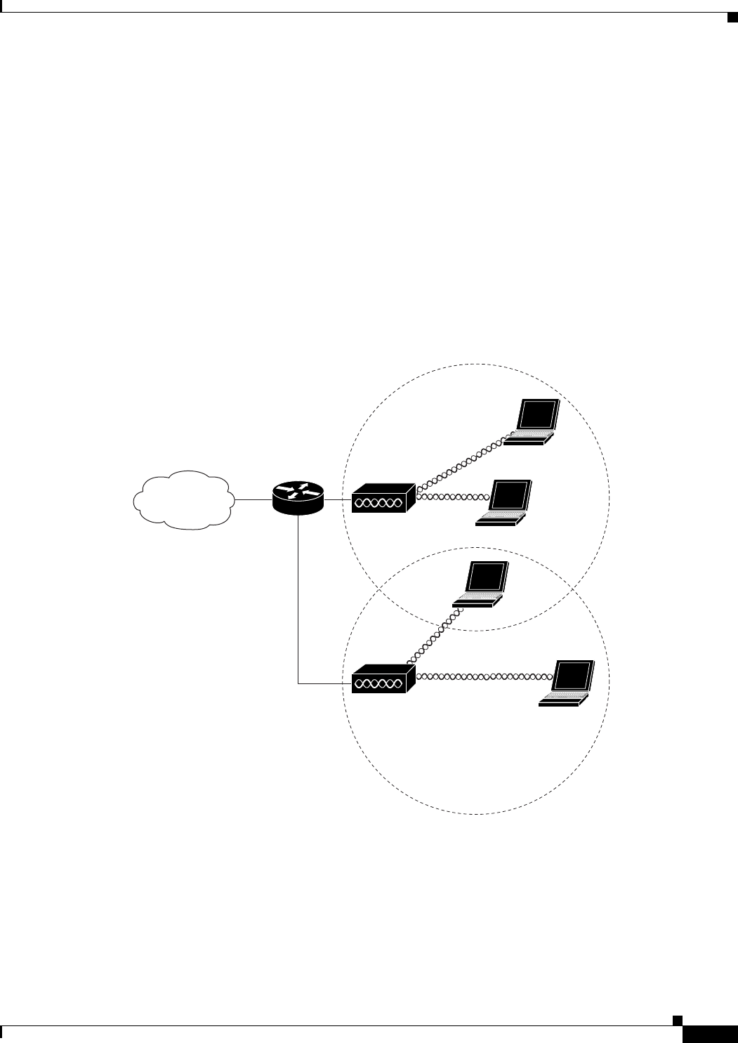
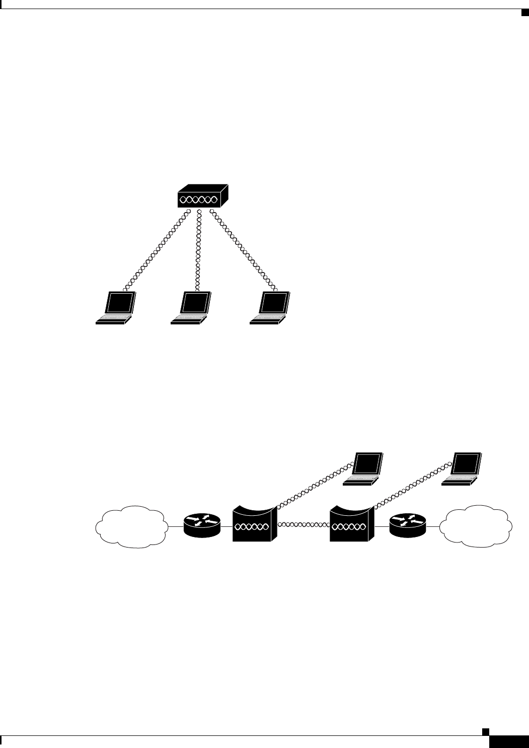
Central Unit in an All-Wireless Network
In an all-wireless network, an access point acts as a stand-alone root unit. The access point is not
attached to a wired LAN; it functions as a hub linking all stations together. The access point serves as
the focal point for communications, increasing the communication range of wireless users. Figure 1-6
shows an access point in an all-wireless network.
Figure 1-6 Access Point as Central Unit in All-Wireless Network
Bridge Network with Wireless Clients
The access point supports root bridge and non-root bridge roles used to interconnect a remote LAN to
the main LAN (see Figure 1-7). The bridge units can also support wireless clients.
Figure 1-7 Root Bridge and Non-root Bridge with Clients
Access point
135443
Root bridge Non-root bridge
135446
CISCO CONFIDENTIAL - Draft 1
1-10
Cisco Aironet 1250AG Series Access Point Hardware Installation Guide
OL-8247-01
Chapter 1 Overview
Network Configuration Examples
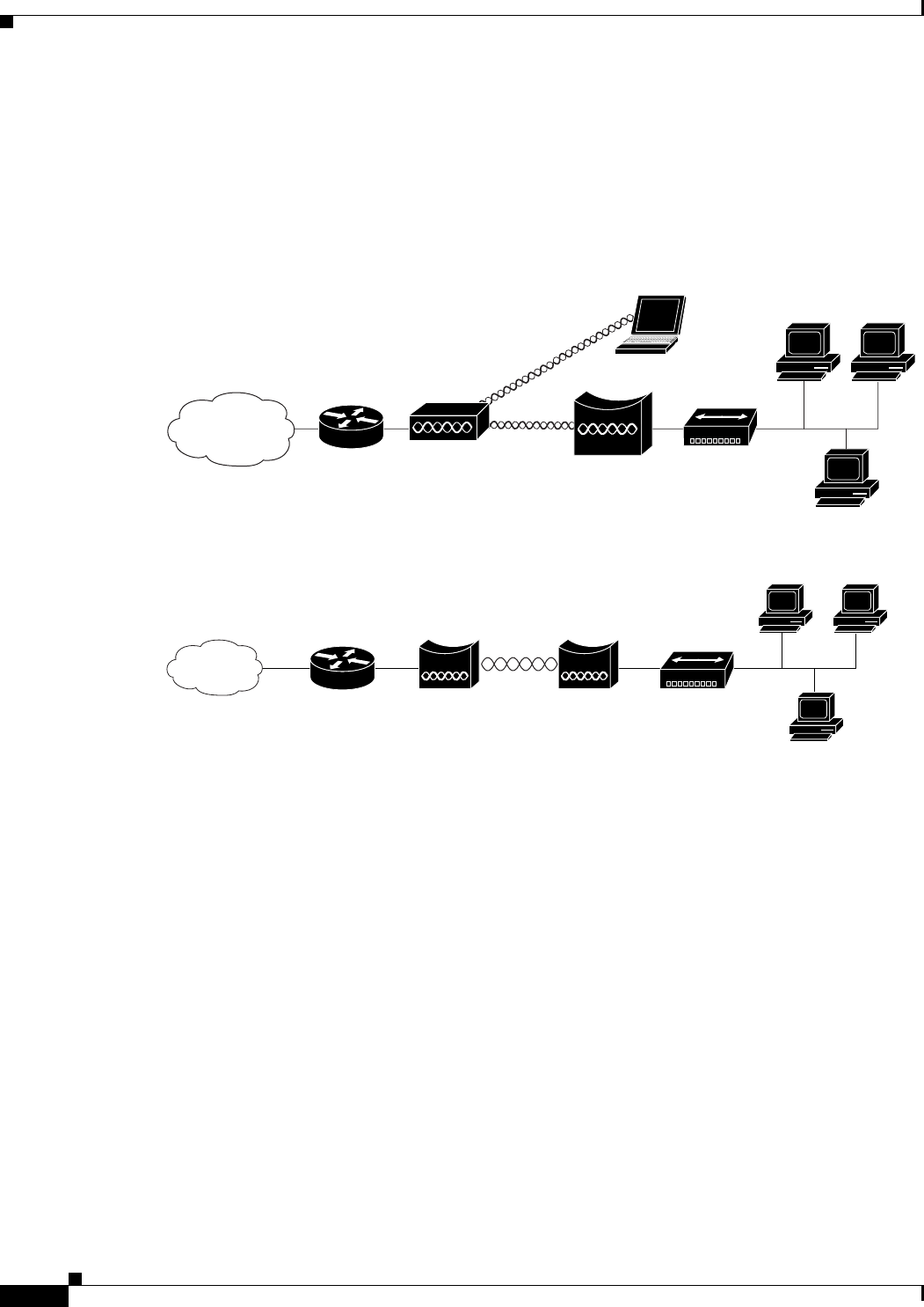
Workgroup Bridge Network
The access point supports a workgroup bridge role to interconnect remote Ethernet workstations to the
main LAN. The workgroup bridge can communicate with an access point (see Figure 1-8) or with a
bridge (see Figure 1-9).
Figure 1-8 Workgroup Bridge Communicating with an Access Point
Figure 1-9 Workgroup Bridge Communicating with a Bridge
Access point
Workgroup bridge
135448
Bridge Workgroup
bridge
135499
CISCO CONFIDENTIAL - Draft 1
1-11
Cisco Aironet 1250AG Series Access Point Hardware Installation Guide
OL-8247-01
Chapter 1 Overview
Network Configuration Examples
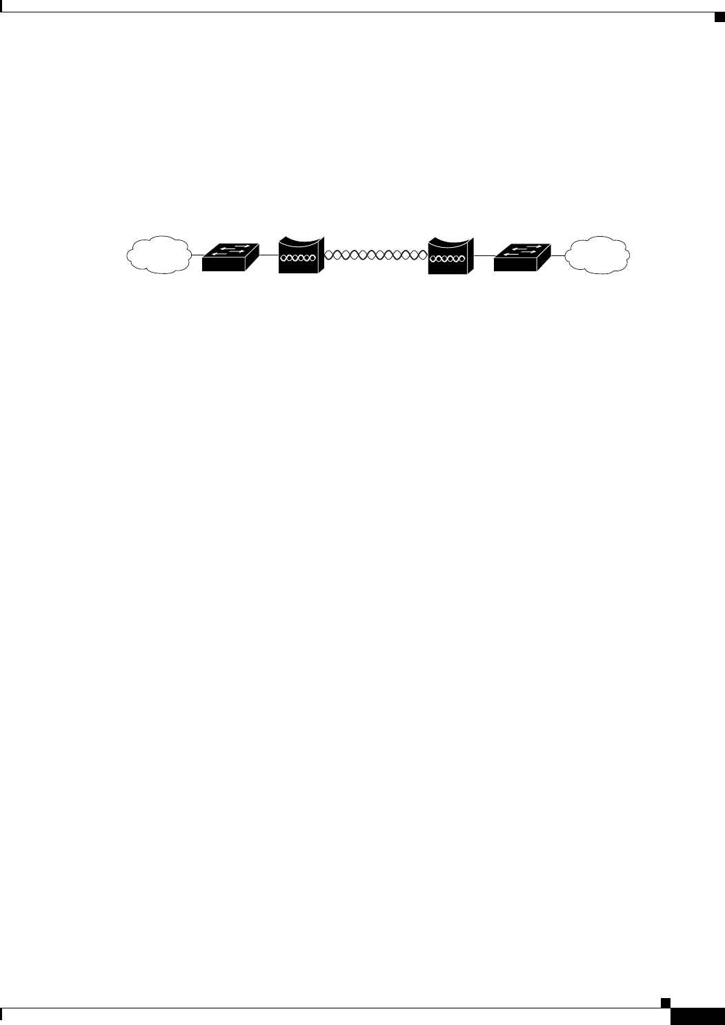
Point-to-Point Bridge Configuration
In a point-to-point bridge configuration, two bridges interconnect two LAN networks using a wireless
communication link (see Figure 1-10). The bridge connected to the main LAN network is classified as
a root bridge and the other bridge is classified as a non-root bridge.
Figure 1-10 Point-to-Point Bridge Configuration
117029
Root bridge Non-root bridge

CISCO CONFIDENTIAL - Draft 1
1-12
Cisco Aironet 1250AG Series Access Point Hardware Installation Guide
OL-8247-01
Chapter 1 Overview
Network Configuration Examples

CISCO CONFIDENTIAL - Draft 1
B-1
Cisco Aironet 1250AG Series Access Point Hardware Installation Guide
OL-8247-01
APPENDIX
B
Declarations of Conformity and Regulatory
Information
This appendix provides declarations of conformity and regulatory information for the Cisco Aironet
1250 Series Access Point and the Cisco Aironet 1250 Series Lightweight Access Point.
This appendix contains the following sections:
•Manufacturers Federal Communication Commission Declaration of Conformity Statement, page
B-2
•Department of Communications—Canada, page B-3
•European Community, Switzerland, Norway, Iceland, and Liechtenstein, page B-3
•Declaration of Conformity for RF Exposure, page B-6
•Guidelines for Operating Cisco Aironet Access Points in Japan, page B-7
•Administrative Rules for Cisco Aironet Access Points in Taiwan, page B-8
•Declaration of Conformity Statements, page B-10
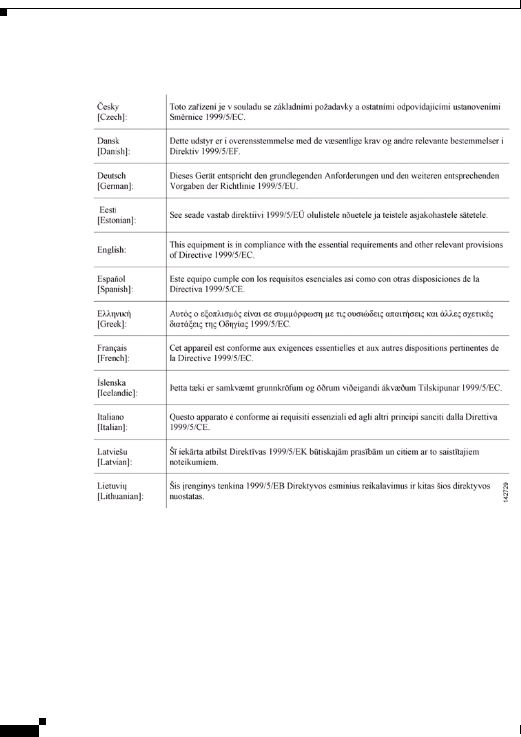
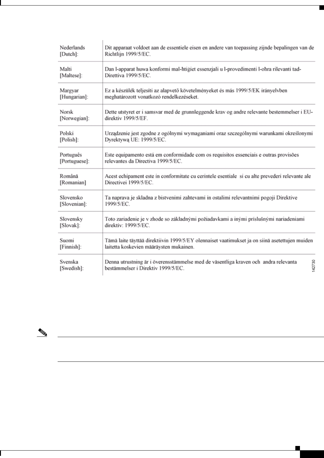
•Declaration of Conformity Statements for European Union Countries, page B-10
CISCO CONFIDENTIAL - Draft 1
B-2
Cisco Aironet 1250AG Series Access Point Hardware Installation Guide
OL-8247-01
Appendix B Declarations of Conformity and Regulatory Information
Manufacturers Federal Communication Commission Declaration of Conformity Statement
Manufacturers Federal Communication Commission
Declaration of Conformity Statement
Manufacturer:
Cisco Systems, Inc.
170 West Tasman Drive
San Jose, CA 95134-1706
USA
This device complies with Part 15 rules. Operation is subject to the following two conditions:
1. This device may not cause harmful interference, and
2. This device must accept any interference received, including interference that may cause undesired
operation.
This equipment has been tested and found to comply with the limits of a Class B digital device, pursuant
to Part 15 of the FCC Rules. These limits are designed to provide reasonable protection against harmful
interference when the equipment is operated in a residential environment. This equipment generates,
uses, and radiates radio frequency energy, and if not installed and used in accordance with the
instructions, may cause harmful interference. However, there is no guarantee that interference will not
occur. If this equipment does cause interference to radio or television reception, which can be determined
by turning the equipment off and on, the user is encouraged to correct the interference by one of the
following measures:
•Reorient or relocate the receiving antenna.
•Increase separation between the equipment and receiver.
•Connect the equipment to an outlet on a circuit different from which the receiver is connected.
•Consult the dealer or an experienced radio/TV technician.
Caution The Part 15 radio device operates on a non-interference basis with other devices operating at this
frequency when using the integrated antennas. Any changes or modification to the product not expressly
approved by Cisco could void the user’s authority to operate this device.
Models Certification Numbers
AIR-RM23A-A-K9 LDK102059
AIR-RM23G-A-K9 LDK102060
Tested To Comply
With FCC Standards
FOR HOME OR OFFICE USE

CISCO CONFIDENTIAL - Draft 1
B-3
Cisco Aironet 1250AG Series Access Point Hardware Installation Guide
OL-8247-01
Appendix B Declarations of Conformity and Regulatory Information
Department of Communications—Canada
Caution Within the 5.15 to 5.25 GHz band (5 GHz radio channels 34 to 48) the U-NII devices are restricted to
indoor operations to reduce any potential for harmful interference to co-channel Mobile Satellite System
(MSS) operations.
Department of Communications—Canada
Canadian Compliance Statement
This Class B Digital apparatus meets all the requirements of the Canadian Interference-Causing
Equipment Regulations.
Cet appareil numerique de la classe B respecte les exigences du Reglement sur le material broilleur du
Canada.
This device complies with Class B Limits of Industry Canada. Operation is subject to the following two
conditions:
1. This device may not cause harmful interference, and
2. This device must accept any interference received, including interference that may cause undesired
operation.
Cisco Aironet 2.4-GHz Access Points are certified to the requirements of RSS-210 for 2.4-GHz spread
spectrum devices, and Cisco Aironet 54-Mbps, 5-GHz Access Points are certified to the requirements of
RSS-210 for 5-GHz spread spectrum devices.The use of this device in a system operating either partially
or completely outdoors may require the user to obtain a license for the system according to the Canadian
regulations. For further information, contact your local Industry Canada office.
European Community, Switzerland, Norway, Iceland, and
Liechtenstein
Models Certification Numbers
AIR-RM23A-A-K9 2461B-102059
AIR-RM23G-A-K9 2461B-102060
Models
AIR-RM23A-E-K9
AIR-RM23G-E-K9
CISCO CONFIDENTIAL - Draft 1
B-4
Cisco Aironet 1250AG Series Access Point Hardware Installation Guide
OL-8247-01
Appendix B Declarations of Conformity and Regulatory Information
European Community, Switzerland, Norway, Iceland, and Liechtenstein
Declaration of Conformity with Regard to the R&TTE Directive 1999/5/EC
CISCO CONFIDENTIAL - Draft 1
B-5
Cisco Aironet 1250AG Series Access Point Hardware Installation Guide
OL-8247-01
Appendix B Declarations of Conformity and Regulatory Information
European Community, Switzerland, Norway, Iceland, and Liechtenstein
For 2.4 GHz radios, the following standards were applied:
•Radio: EN 300.328-1, EN 300.328-2
•EMC: EN 301.489-1, EN 301.489-17
•Safety: EN 60950
Note This equipment is intended to be used in all EU and EFTA countries. Outdoor use may be restricted to
certain frequencies and/or may require a license for operation. For more details, contact Cisco Corporate
Compliance.

CISCO CONFIDENTIAL - Draft 1
B-6
Cisco Aironet 1250AG Series Access Point Hardware Installation Guide
OL-8247-01
Appendix B Declarations of Conformity and Regulatory Information
Declaration of Conformity for RF Exposure
For 54 Mbps, 5 GHz access points, the following standards were applied:
•Radio: EN 301.893
•EMC: EN 301.489-1, EN 301.489-17
•Safety: EN 60950
The following CE mark is affixed to the access point with a 2.4 GHz radio and a 54 Mbps, 5 GHz radio:
Declaration of Conformity for RF Exposure
The radio has been found to be compliant to the requirements set forth in CFR 47 Sections 2.1091, and
15.247 (b) (4) addressing RF Exposure from radio frequency devices as defined in Evaluating
Compliance with FCC Guidelines for Human Exposure to Radio Frequency Electromagnetic Fields. The
equipment shoud be installed more than 20 cm (7.9 in.) from your body or nearby persons.
The access point must be installed to maintain a minimum 20 cm (7.9 in.) co-located separation distance
from other FCC approved indoor/outdoor antennas used with the access point. Any antennas or
transmitters not approved by the FCC cannot be co-located with the access point. The access point’s
co-located 2.4 GHz and 5 GHz integrated antennas support a minimum separation distance of
8 cm (3.2 in.) and are compliant with the applicable FCC RF exposure limit when transmitting
simultaneously.
Note Dual antennas used for diversity operation are not considered co-located.
CISCO CONFIDENTIAL - Draft 1
B-7
Cisco Aironet 1250AG Series Access Point Hardware Installation Guide
OL-8247-01
Appendix B Declarations of Conformity and Regulatory Information
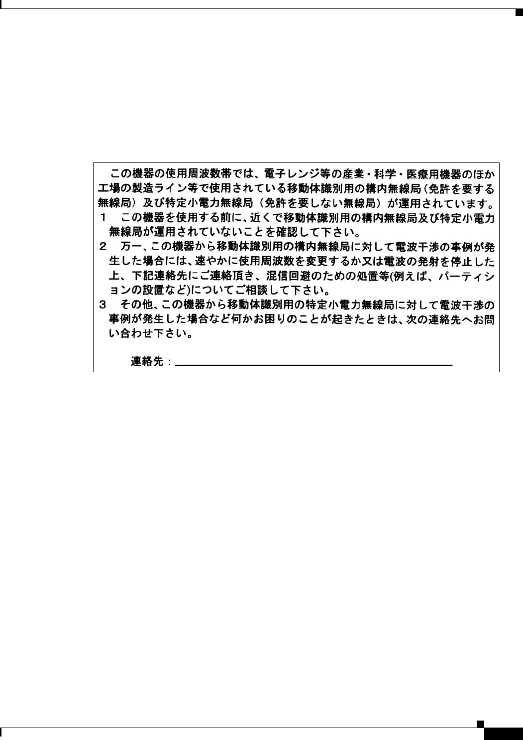
Guidelines for Operating Cisco Aironet Access Points in Japan
Guidelines for Operating Cisco Aironet Access Points in Japan
This section provides guidelines for avoiding interference when operating Cisco Aironet access points
in Japan. These guidelines are provided in both Japanese and English.
Japanese Translation
English Translation
This equipment operates in the same frequency bandwidth as industrial, scientific, and medical devices
such as microwave ovens and mobile object identification (RF-ID) systems (licensed premises radio
stations and unlicensed specified low-power radio stations) used in factory production lines.
1. Before using this equipment, make sure that no premises radio stations or specified low-power radio
stations of RF-ID are used in the vicinity.
2. If this equipment causes RF interference to a premises radio station of RF-ID, promptly change the
frequency or stop using the device; contact the number below and ask for recommendations on
avoiding radio interference, such as setting partitions.
3. If this equipment causes RF interference to a specified low-power radio station of RF-ID, contact
the number below.
Contact Number: 03-5549-6500
03-5549-6500
43768

CISCO CONFIDENTIAL - Draft 1
B-8
Cisco Aironet 1250AG Series Access Point Hardware Installation Guide
OL-8247-01
Appendix B Declarations of Conformity and Regulatory Information
Administrative Rules for Cisco Aironet Access Points in Taiwan
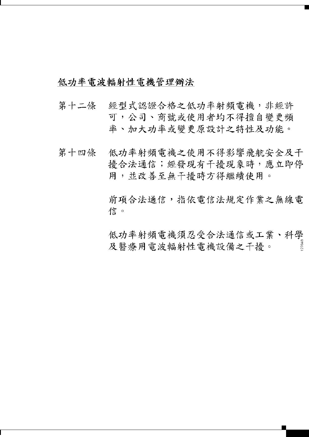
Administrative Rules for Cisco Aironet Access Points in Taiwan
This section provides administrative rules for operatingCisco Aironet access points inTaiwan. The rules
are provided in both Chinese and English.
Access Points with IEEE 802.11a Radios
Chinese Translation
English Translation
This equipment is limited for indoor use.
CISCO CONFIDENTIAL - Draft 1
B-9
Cisco Aironet 1250AG Series Access Point Hardware Installation Guide
OL-8247-01
Appendix B Declarations of Conformity and Regulatory Information
Administrative Rules for Cisco Aironet Access Points in Taiwan
All Access Points
Chinese Translation
English Translation
Administrative Rules for Low-power Radio-Frequency Devices
Article 12
For those low-power radio-frequency devices that have already received a type-approval, companies,
business units or users should not change its frequencies, increase its power or change its original
features and functions.
Article 14
The operation of the low-power radio-frequency devices is subject to the conditions that no harmful
interference is caused to aviation safety and authorized radio station; and if interference is caused, the
user must stop operating the device immediately and can't re-operate it until the harmful interference is
clear.
The authorized radio station means a radio-communication service operating in accordance with the
Communication Act.
The operation of the low-power radio-frequency devices is subject to the interference caused by the
operation of an authorized radio station, by another intentional or unintentional radiator, by industrial,
scientific and medical (ISM) equipment, or by an incidental radiator.

CISCO CONFIDENTIAL - Draft 1
B-10
Cisco Aironet 1250AG Series Access Point Hardware Installation Guide
OL-8247-01
Appendix B Declarations of Conformity and Regulatory Information
Declaration of Conformity Statements
Declaration of Conformity Statements
All the Declaration of Conformity statements related to this product can be found at the following URL:
http://www.ciscofax.com
Declaration of Conformity Statements for European Union
Countries
The Declaration of Conformity statement for the European Union countries is listed below:
----- TBD------

CISCO CONFIDENTIAL - Draft 1
B-11
Cisco Aironet 1250AG Series Access Point Hardware Installation Guide
OL-8247-01
Appendix B Declarations of Conformity and Regulatory Information
Declaration of Conformity Statements for European Union Countries

CISCO CONFIDENTIAL - Draft 1
B-12
Cisco Aironet 1250AG Series Access Point Hardware Installation Guide
OL-8247-01
Appendix B Declarations of Conformity and Regulatory Information
Declaration of Conformity Statements for European Union Countries

CISCO CONFIDENTIAL - Draft 1
D-1
Cisco Aironet 1250AG Series Access Point Hardware Installation Guide
OL-8247-01
APPENDIX
D
Channels and Power Levels
This appendix lists the IEEE 802.11b/g (2.4-GHz) and the IEEE 802.11a (5-GHz) channels and
maximum power levels supported by the world’s regulatory domains.
The following topic is covered in this appendix:
•Channels and Maximum Power Levels, page D-2
•External Antenna Settings, page D-5
CISCO CONFIDENTIAL - Draft 1
D-2
Cisco Aironet 1250AG Series Access Point Hardware Installation Guide
OL-8247-01
Appendix D Channels and Power Levels
Channels and Maximum Power Levels
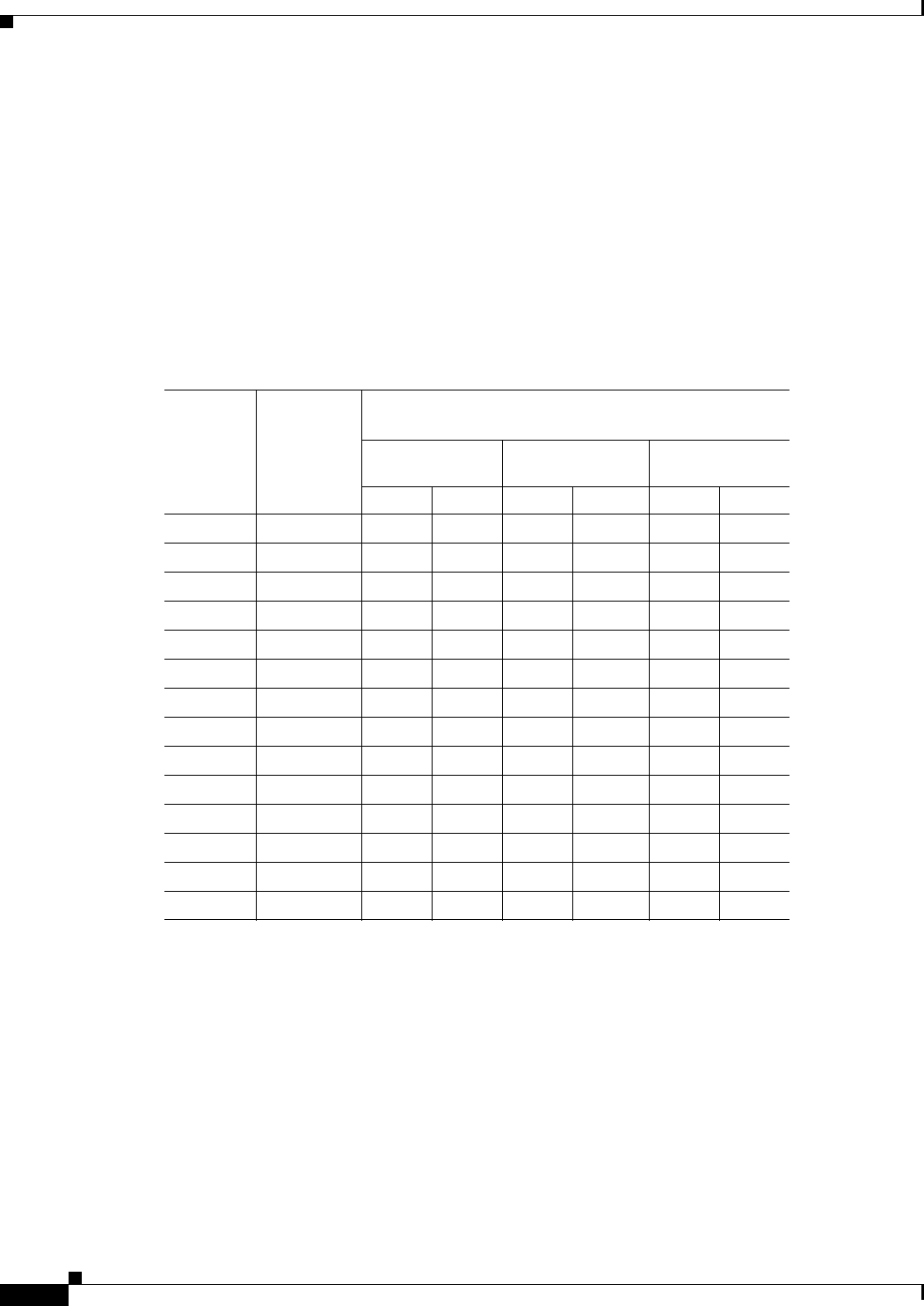
Channels and Maximum Power Levels
IEEE 802.11b/g (2.4-GHz Band) on Single Radio Models
An improper combination of power level and antenna gain can result in equivalent isotropic radiated
power (EIRP) above the amount allowed per regulatory domain. Table 1 indicates the channel identifiers,
channel center frequencies, and maximum power levels for each channel allowed by the regulatory
domains:
.
Table 1 Channels and Maximum Conducted Power for the 802.11b/g Radio with up to 10 dBi
Antennas
Channel ID
Center
Frequency
(MHz)
Maximum Conducted Power Levels (dBm) in the
Regulatory Domains
Americas
(–A)
EMEA
(–E)
Japan
(–P)
CCK OFDM CCK OFDM CCK OFDM
12412201717
1
1. Indicates the power level settings shipped from the factory. You might need to reset the maximum
power levels used with your external antenna (see Table D-4).
17114 14
22417201717
117114 14
32422201717
117114 14
42427201717
117114 14
52432201717
117114 14
62437201717
117114 14
72442201717
117114 14
82447201717
117114 14
92452201717
117114 14
10 2457 20 17 17117114 14
11 2462 20 17 17117114 14
12 2467 – – 17117114 14
13 2472 – – 17117114 14
14 2484 – – – – 14 –

CISCO CONFIDENTIAL - Draft 1
D-3
Cisco Aironet 1250AG Series Access Point Hardware Installation Guide
OL-8247-01
Appendix D Channels and Power Levels
Channels and Maximum Power Levels
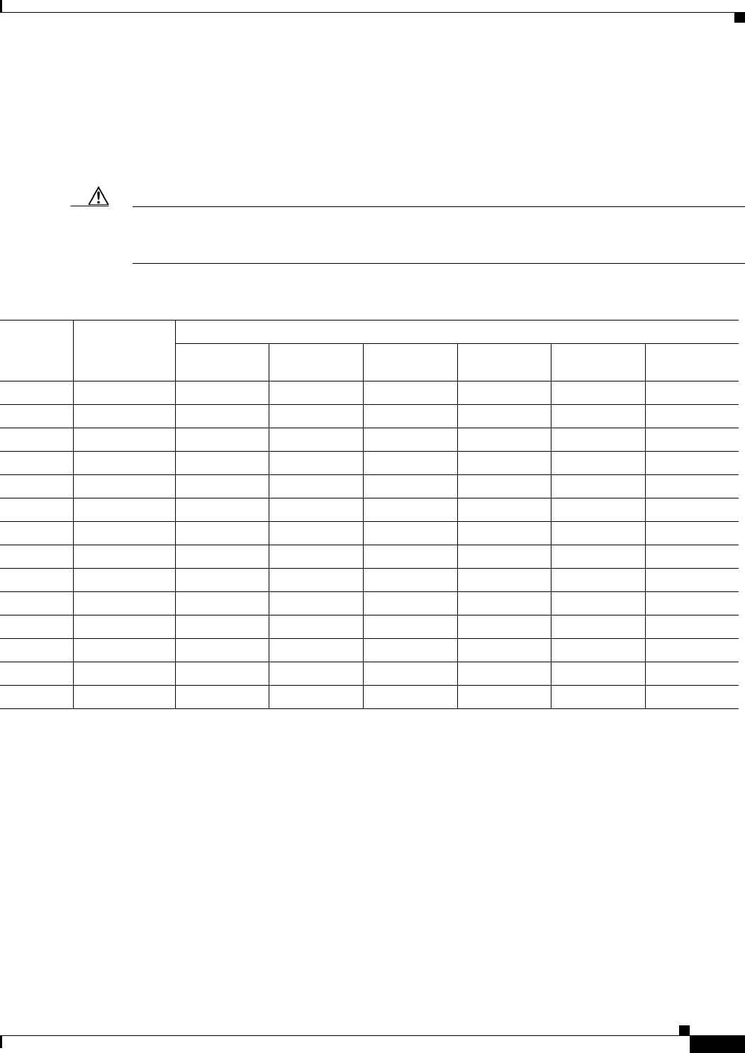
IEEE 802.11b/g (2.4-GHz Band) on Dual Radio Models
An improper combination of power level and antenna gain can result in equivalent isotropic radiated
power (EIRP) above the amount allowed per regulatory domain. Table D-2 indicates the channel
identifiers, channel center frequencies, and maximum power levels for each channel allowed by the
regulatory domains:
IEEE 802.11a (5-GHz Band)
An improper combination of power level and antenna gain can result in equivalent isotropic radiated
power (EIRP) above the amount allowed per regulatory domain.
Table D-3 indicates the channel identifiers, channel center frequencies, and maximum power levels for
each IEEE 802.11a 20-MHz-wide channel allowed by the regulatory domains:
Table D-2 Channels and Maximum Conducted Power for the 802.11b/g Radio with up to 10 dBi Antennas
Channel
ID
Center
Freq
(MHz)
Maximum Conducted Power Levels (dBm) in the Regulatory Domains
Americas
(-A)
China
(-C)
EMEA
(-E)
Israel
(-I)
South Korea
(-K)
Non-FCC
(-N)
Japan
(-P)
Singapore
(-S)
Taiwan
(-T)
CCK OFDM CCK OFDM CCK OFDM CCK OFDM CCK OFDM CCK OFDM CCK OFDM CCK OFDM CCK OFDM
1 2412201717171717171717172017141417172017
2 2417201717171717171717172017141417172017
3 2422201717171717171717172017141417172017
4 2427201717171717171717172017141417172017
5 2432201717171717171717172017141417172017
6 2437201717171717171717172017141417172017
7 2442201717171717171717172017141417172017
8 2447201717171717171717172017141417172017
9 2452201717171717171717172017141417172017
10 2457 20 17 17 17 17 17 17 17 17 17 20 17 14 14 17 17 20 17
11 2462 20 17 17 17 17 17 17 17 17 17 20 17 14 14 17 17 20 17
12 2467 – – 17 17 17 17 17 17 17 17 – – 14 14 17 17 – –
13 2472 – – 17 17 17 17 17 17 17 17 – – 14 14 17 17 – –
142484––––––––––––14–––––

CISCO CONFIDENTIAL - Draft 1
D-4
Cisco Aironet 1250AG Series Access Point Hardware Installation Guide
OL-8247-01
Appendix D Channels and Power Levels
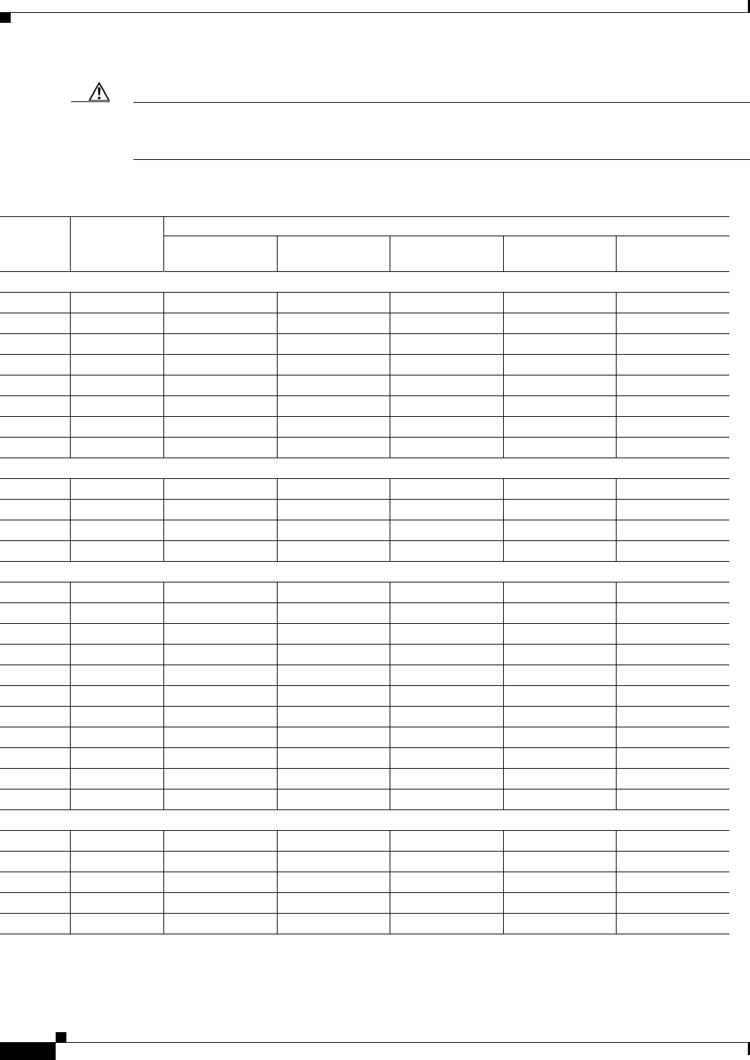
Channels and Maximum Power Levels
Table D-3 Channels and Maximum Conducted Power for IEEE 802.11a Radio with up to 9.5 dBi Antennas
Channel
ID
Center
Frequency
(MHz)
Maximum Conducted Power Levels (dBm) in the Regulatory Domains
Americas
(–A)
China
(–C)
EMEA
(–E)1
1. Indicates the power level settings shipped from the factory. You might need to reset the maximum power levels used with your external
antennas (see Table D-5).
Israel
(–I)
South
Korea
(–K)
North
America
(–N)
Japan
(–P)
Singapore
(–S)
Taiwan
(–T)
UNII-1 (5150-5250 MHz)
34 5170 – – – – – – – – –
36 5180 11 – 17 17115 11 11 14 –
38 5190 – – – – – – – – –
40 5200 11 – 17 17115 11 11 14 –
42 5210 – – – – – – – – –
44 5220 11 – 17 17115 11 11 14 –
46 5230 – – – – – – – – –
48 5240 11 – 17 17115 11 11 14 –
5250 to 5350 MHz
52 5260 172
2. Indicated frequencies require DFS (Uniform spreading not required for the -P domain)
–17
217217217 82112–
56 5280 172–17
217217217 8211211
60 5300 172–17
217217217 8211211
64 5320 112–17
217217211 8211211
5470 to 5725 MHz
100 5500 172–17
2–17
2–– –17
2
104 5520 172–17
2–17
2–– –17
2
108 5540 172–17
2–17
2–– –17
2
112 5560 172–17
2–17
2–– –17
2
116 5580 172–17
2–17
2–– –17
2
120 5600 – – 172–17
2–– –17
2
124 5620 – – 172–17
2–– –17
2
128 5640 – – 172–– – – –17
2
132 5660 172–17
2–– – – – 17
2
136 5680 172–17
2–– – – – 17
2
140 5700 172–17
2–– – – – 17
2
5725 to 5850 MHz
149 5745 17 17 – – 17 17 – 17 17
153 5765 17 17 – – 17 17 – 17 17
157 5785 14 17 – – 17 14 – 17 14
161 5805 11 17 – – 17 11 – 17 11
165 5825 11 17 – – – 11 – 17 –
CISCO CONFIDENTIAL - Draft 1
D-5
Cisco Aironet 1250AG Series Access Point Hardware Installation Guide
OL-8247-01
Appendix D Channels and Power Levels
External Antenna Settings
External Antenna Settings
Maximum Power Levels in Some Regulatory Domains with External Antennas
Caution To avoid exceeding maximum conducted power levels in the China (–C), EMEA (-E), South Korea (–K),
Israel (–I), and Singapore (–S) regulatory domains when using an 802.11b/g radio with 2.2- to 10-dBi
external antennas, you must manually set the access point output power level as shown in Table D-4.
Table D-4 Maximum Power Levels for the 802.11b/g Radio in the (–C), (–E), (–K), (–I), and (–S) Regulatory Domains
Channel
ID
Center
Frequency
(MHz)
Maximum Power Levels (dBm)
2.2 dBi
Antenna
5.2 dBi
Antenna
6.0 dBi
Antenna
6.5dBi
Antenna
9.0 dBi
Antenna
10 dBi
Antenna
124121714141111 8
224171714141111 8
324221714141111 8
424271714141111 8
524321714141111 8
624371714141111 8
724421714141111 8
824471714141111 8
924521714141111 8
10 2457 17 14 14 11 11 8
11 2462 17 14 14 11 11 8
12 2467 17 14 14 11 11 8
13 2472 17 14 14 11 11 8
142484––––––
CISCO CONFIDENTIAL - Draft 1
D-6
Cisco Aironet 1250AG Series Access Point Hardware Installation Guide
OL-8247-01
Appendix D Channels and Power Levels
External Antenna Settings
Caution To avoid exceeding maximum conducted power levels in the EMEA (-E) and Israel (–) regulatory
domains when using a IEEE 802.11a radio with 6.0- to 9.5-dBi external 5-MHz antennas, you must
manually set the access point output power level as shown in Table D-5.
Table D-5 Maximum Power Levels for IEEE 802.11a Radio in the EMEA(–E) and Israel (–I) Regulatory Domains
Channel
ID
Center
Frequency
(MHz)
Maximum Power Levels (dBm)
3.5 dBi Antenna 4.5 dBi Antenna 6.0 dBi Antenna 7.0 dBi Antenna 9.5 dBi Antenna
UNII-1 (5150-5250 MHz)
345170 –––––
36 5180 17 17 15 15 11
385190 –––––
40 5200 17 17 15 15 11
425210 –––––
44 5220 17 17 15 15 11
465230 –––––
48 5240 17 17 15 15 11
5250 to 5350 MHz
52 5260 17 17 15 15 11
56 5280 17 17 15 15 11
60 5300 17 17 15 15 11
64 5320 17 17 15 15 11
5470 to 5725 MHz
100 5500 17 17 17 17 17
104 5520 17 17 17 17 17
108 5540 17 17 17 17 17
112 5560 17 17 17 17 17
116 5580 17 17 17 17 17
120 5600 17 17 17 17 17
124 5620 17 17 17 17 17
128 5640 17 17 17 17 17
132 5660 17 17 17 17 17
136 5680 17 17 17 17 17
140 5700 17 17 17 17 17
5725 to 5850 MHz
1495745–––––
1535765–––––
1575785–––––
1615805–––––
1655825–––––