Cisco Systems 102063 802.11a Radio Module User Manual 1520 ch1
Cisco Systems Inc 802.11a Radio Module 1520 ch1
User Manual

CHAPTER
CISCO CONFIDENTIAL - Draft 1
1-1
Cisco Aironet 1520 Series Outdoor Mesh Access Point Hardware Installation Guide
OL-12632-01
1
Overview
The Cisco Aironet 1520 Series Outdoor Mesh Access Point (hereafter called the access point) is a
wireless device designed for wireless client access, point-to-point bridging, point-to-multipoint
bridging, and point-to-multipoint mesh wireless connectivity. The access point is a standalone unit that
can be mounted on a streetlight pole or on a building wall or overhang. It is a self-contained outdoor unit
that can be configured with a wired backhaul connection to an Ethernet segment for a rooftop
deployment or can be configured with a wireless backhaul for a pole-top deployment. The access point
can be installed where power is available without the need for a wired network connection.
The access point is available in two models: LAP1522 (supports 2.4-GHz and 5-GHz radios) and
LAP1521 (supports a 2.4-GHz radio).The access point provides client access and wireless mesh
backhaul that supports 6 to 54 Mbps data rates without the need for a license. The LAP1522 model
dedicates the 5-GHz radio for backhaul operations to reach a wired network and uses the 2.4-GHz radio
for wireless clients. The LAP1521 model uses the 2.4- or 5-GHz radio for both backhaul and wireless
clients.
The access point can also operate as a relay node for other access points not directly connected to a wired
network. Intelligent wireless routing is provided by the patent-pending Adaptive Wireless Path Protocol
(AWPP). This enables each access point to identify its neighbors and intelligently choose the optimal
path to the wired network by calculating the cost of each path in terms of signal strength and the number
of hops required to get to a controller.
The access point is configured, monitored, and operated through a Cisco wireless LAN controller
(hereafter called a controller) as described in the Cisco Wireless LAN Controller Configuration Guide.
The Deployment Guide: Cisco Mesh Networking Solution describes how to plan and initially configure
the Cisco Mesh network, which supports wireless point-to-point, point-to-multipoint, and mesh
deployments. The controllers use a browser-based management system, a command-line interface (CLI),
or the Cisco Wireless Control System (WCS) network management system to manage the controller and
the associated access points. The access point is compliant with Wi-Fi Protected Access (WPA2) and
employs hardware-based Advanced Encryption Standard (AES) encryption between wireless nodes to
provide end-to-end security.
This chapter provides information on the following topics:
•Main Hardware Features, page 2
•Network Configuration Examples, page 6

2
Overview
OL-12632-01
Main
Hardware
Features
Some of the access point’s main hardware features are listed below:
•One or two radios (2.4- and 5-GHz)—see the “Single or Dual Radio Operation” section on page 3
•External radio antennas—see the “External Antennas” section on page 3
•Multiple power sources—see the “Multiple Power Sources” section on page 4
•Rugged metal enclosure—see the “Metal Enclosure” section on page 5
•Optional Ethernet ports—see the “Ethernet Ports” section on page 5
•Optional cable modem—see the
•Optional hardware—see the “Optional Hardware” section on page 6
–
Cable strand mount kit
–
Pole mount kit
–
150 ft (45.72 m) Ethernet outdoor cable
•Optional battery backup—future availability
Figure 1 shows the access point connectors.
Figure 1 Access Point Connectors
14
25
36

Connectors
The optional featues of the access point support these connectors (see Figure 1):
•Ethernet (PoE) uplink connector—(type RJ45 with TBD for waterproofing)
•Ethernet downlink connector—(type RJ45 with TBD for waterproofing)
•Three Type N antenna connectors (2.4-GHz radio)
•One Type N antenna connector (5-GHz radio)
•Fiber-optic connector—Small form factor pluggable (SFP)
•Power-over-cable (POC) connector—(TBD)
•AC power connector
Single or Dual Radio Operation
The access point is available in two models: LAP1522 (supports 2.4-GHz and 5-GHz radios) and
LAP1521 (supports a 2.4- or 5-GHz radio). The radios use external antennas (see “External Antennas”).
The LAP1522 model supports simultaneous dual-radio operation using a 2.4-GHz 802.11b/g radio and
a 5-GHz 802.11a radio. The LAP1521 model supports both mesh backhaul operation and wireless
clients using a single 2.4- or 5-GHz radio.
The 5-GHz radio incorporates an Unlicensed National Information Infrastructure (UNII) radio
transceiver operating in the UNII 5-GHz frequency bands. The 5-GHz radio on the access point is used
for backhaul operations to the controller. The 5-GHz radio can also operate in the 4.9-GHz Public
Safety band in the United States.
Note The 4.9-GHz band requires a license and may be used only by qualified Public Safety operators
as defined in section 90.20 of the FCC rules.
The 2.4-GHz radio supports three antennas for multi-input, single output (MISO) operation. The radio
uses three receivers to support maximum ratio combining (MRC) to enhance receiver performance.
MRC is a technique that combines the signals from multiple receivers in a manner to optimize the
signals. MRC can provide up to 3 dB of increased receive signal strength.
The access point does not support both radios configured for backhaul support
External Antennas
The access point is equipped with three N-type radio frequency (RF) connector on the top of the unit
for external 2.4-GHz antennas to support multiple input single output (MISO) operation. The LAP1522
model also has one to three N-type RF connectors on the bottom of the unit for external 5-GHz antennas
(see Figure 1). When using the optional Cisco compact omnidirectional antennas, the 2.4- and 5-GHz
antennas connect directly to the access point. The Cisco omnidirectional antennas use vertical
polarization.
The access point can also be equipped with specific third-party external antennas (see Table 1 and
Table 2), subject to local regulatory requirements. When you are installing third-party antennas, they
must be installed with all waterproofing steps recommended by the third-party manufacturer.
Note When you mount the access point in an indoor environment, you must also mount the antennas
in an indoor environment.
Warning
Only trained and qualified personnel should be allowed to install, replace, or service
this equipment.
Statement 1030

4
Overview
OL-12632-01
Table 1 and Table 2 lists the supported external antennas for the access point.
Multiple Power Sources
The access point supports these power sources:
•Power-over-Ethernet (POE)—1520 power injector
•AC power—90 to 480 VAC
•Quazi-AC power-over-cable (POC)—40 to 90 V
•External 12 VDC
•Internal battery
The access point can be connected to more than one power source. The access point detects the
available input sources and switches to the preferred power source using the following default
prioitization:
•AC power or POC power
•External 12VDC power
•1250 Power Injetor PoE power
•Internal Battery power
Note The power source default prioritization can be user reconfigured.
Caution To provide inline PoE, you must use the 1250 power injector. Other power injectors, PoE
switches, and 802.3af power sources cannot provide adequate power, which may cause the
access point to malfunction and cause over-current conditions at the power source. You
must ensure that the switch port connected to the access point has PoE turned off.
Caution The power injector and the power module must be used in an indoor environment only.
Table 1 External 5-GHz Antennas
Part Number Model Gain (dBi)
AIR-ANT5180V-N 5-GHz compact omnidirectional1
1. The compact omnidirectional antennas mount directly on the access point.
8
4.9-GHz compact omnidirectional2
2. The use of the 4.9-GHz band requires a license and may be used only by qualified Public Safety operators as defined in
section 90.20 of the FCC rules.
7
AIR-ANT58G10SSA-N 5-GHz sector 9.5
AIR-ANT5114P-N 4.9- to 5-GHz patch214.0
AIR-ANT5117S-N 4.9- to 5-GHz 90-degree sector217.0
Table 2 External 2.4-GHz Antennas
Part Number Model Gain (dBi)
AIR-ANT2450V-N 2.4-GHz compact omnidirectional1
1. The compact omnidirectional antennas mount directly on the access point.
5.5
AIR-ANT2480V-N 2.4 GHz omnidirectional 8.0

Caution When the access point is installed outdoors or in a wet or damp location, the AC branch
circuit that is powering the access point should be provided with ground fault protection
(GFCI), as required by Article 210 of the National Electrical Code (NEC).
The AC power cord options are listed below:
•40-ft (12.2-m) power cord for light pole installations in the US and Canada.
•40-ft (12.2-m) power cord for use outside the US and Canada. One end of the power cord is
terminated with an access point AC power connector and the other end is unterminated.
•4-ft (1.2-m) streetlight power tap adapter for light pole installations in the US and Canada.
Ethernet Ports
The access point supports an Ethernet uplink port and a downlink port. The access point’s Ethernet
uplink port uses an RJ-45 connector (with weatherproofing) to link the access point to your10BASE-T,
100BASE-T, or 1000BASE-T network. The Ethernet cable is used to send and receive Ethernet data and
to optionally supply inline 56-VDC power from the power injector.
The access point’s downlink Ethernet port uses an RJ-45 connector (with weatherproofing) to provide
LAN connectivity and IEEE 802.3af power to a peripheral customer device, such as a camera or sensor
gateway.
The Ethernet MAC addresses are printed on the label on the side of the access point (refer to the
“Finding the Product Serial Number - TBD” section on page 13).
Tips The access point senses the Ethernet and power signals and automatically switches
internal circuitry to match the cable connections.
Caution To provide inline PoE, you must use the 1520 power injector. Other power injectors, PoE
switches, and 802.3af power sources can not provide adequate power, which may cause
the access point to malfunction and cause possible over-current conditions at the power
source.
Metal Enclosure
The access point uses a metal enclosure that can accommodate both indoor or outdoor operating
environments and an industrial temperature operating range of (–40°F (–40°C ) to 131°F (55°C). The
access point complies with NEMA Type 4X and IP66 requirements from IEC60529.
Note When the access point is mounted indoors, the antennas must also be mounted indoors.
Cable Modem

6
Overview
OL-12632-01
Optional
Hardware
Some of the access point hardware options are listed below:
•Cable modem—DOCSIS 2.0 compatible for direct connection to cable lines.
•Fiber optic module—uses Small Form Factor Pluggable (SFP) connections for connection to fiber
optic lines.
–
Supports 100BaseBX modules
–
Supports 15.5 mi (25 km) of fiber-optic cable.
•Pole mount kit (SKU - TBD)—provides hardware for mounting the access point to the top of a
metal or wood pole, such as a streetlight pole.
•Streetlight power tap adapter (SKU - TBD)—connects to the light control connector on a streetlight
pole and provides AC power to the access point.
•Outdoor rated Ethernet cable (???)—used to supply Ethernet and optional DC power to the access
point.
•1520 power injector (SKU - TBD)—provides power-over-Ethernet (PoE) to the access point.
•AC power cord (for additional information, refer to the “Multiple Power Sources” section on
page 4).
•Future availability—battery backup module (80 Watt hour (WHr). The integrated battery can be
used to power the unit when external power sources are not available.
–
Four hour access point operation using two radios at 77oF (25oC)—with PoE output port off
–
Two hour access point operation using two radios at 77oF (25oC)— with PoE output port on
–
User installable and replaceable
•
Network Configuration Examples
The access point is a wireless device designed for wireless client access and point-to-point bridging,
point-to-multipoint bridging, and point-to-multipoint mesh wireless connectivity. The access point
provides 5-GHz backhaul capability to link with another access point to reach a wired network
—connection or to provide repeater operations for other access points.
The access point plays two primary radio roles: a root access point (hereafter called a RAP) or a
non-root access point (hereafter called a MAP). When the access point has a wired Ethernet connection
to the controller (through a switch), the radio role is called a RAP. A RAP is a parent node to any
bridging or mesh network. A controller can support one or more RAPs, each one parenting the same or
different wireless networks. There can be more than one RAP for the same mesh network for
redundancy. RAPs also support wireless clients on the band not being used for the backhaul interface.
When the access point does not have a wired Ethernet connection to the controller (through a switch),
the radio role is called a MAP. The MAPs have a wireless connection (through the backhaul interface)
to other MAPs and finally to a RAP with an Ethernet connection through a switch to the controller.
MAPs may also have a wired Ethernet connection to a local LAN and serve as a bridge endpoint for that
LAN (using a point-to-point or point-to-multipoint bridge connection). MAPs also support wireless
clients on the band not used for the backhaul interface.
Wireless
Backhaul
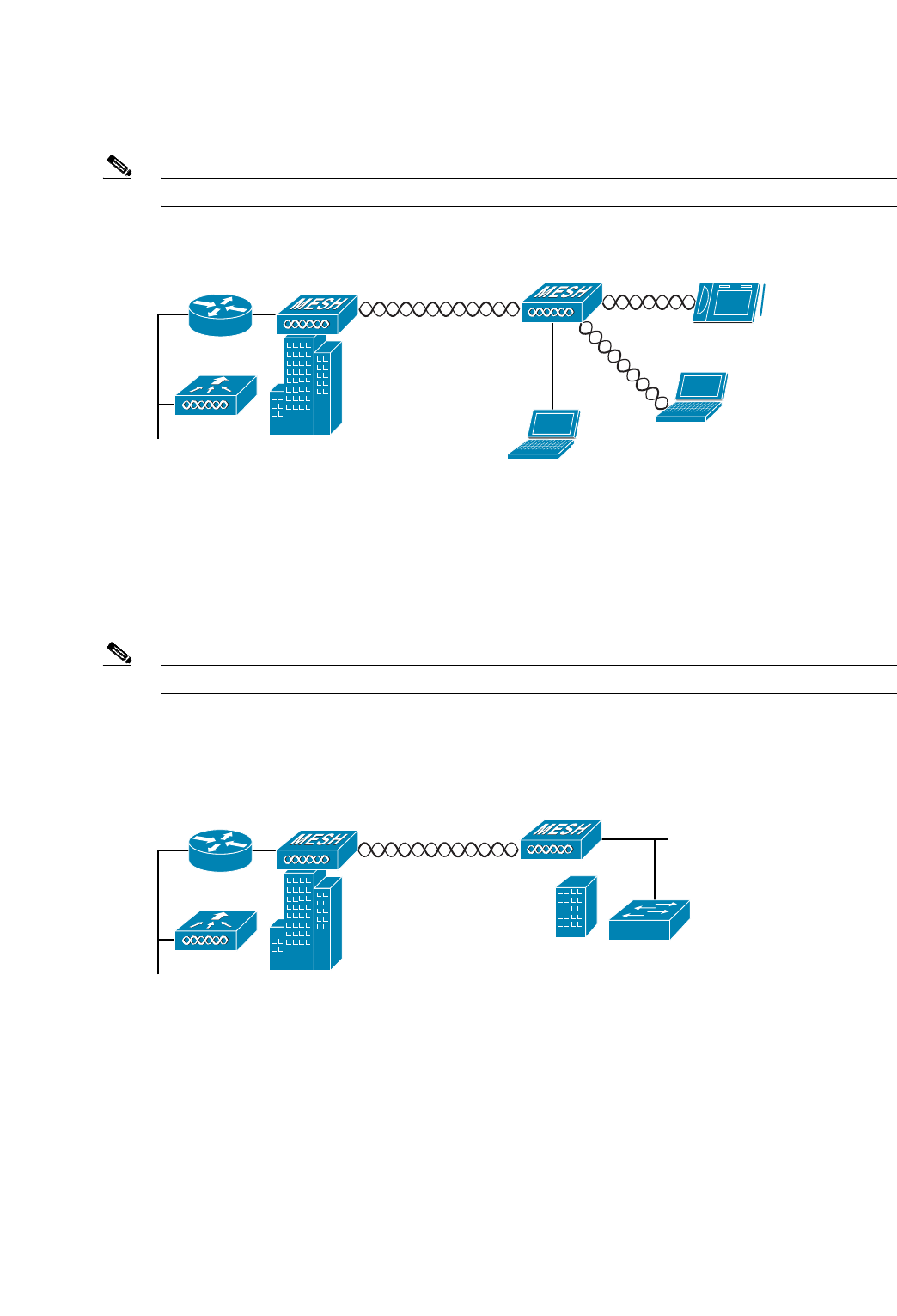
The access point supports wireless backhaul capability using the 5-GHz radio to bridge to another
access point to reach a wired network connection to a controller (see Figure 2). The access point
connected to the wired network is considered a RAP in this configuration. The remote access point is
considered a MAP and transfers wireless client traffic to the RAP for transfer to the wired network.
Lightweight access point protocol (LWAPP) control traffic is also transferred over this bridged link.
Note The LAP 1505 model uses the 2.4-GHz radio for backhaul and wireless client operations.
Figure 2 Access Point Backhaul Example
Point-to-Point Bridging
The access points can be used to extend a remote network by using the 5-GHz backhaul radio to bridge
the two network segments as shown in Figure 3. To support Ethernet bridging, you must enable bridging
on the controller for each access point.
Note The LAP 1505 model uses the 2.4-GHz radio for bridging operations.
Wireless client access is supported; however, if bridging between tall buildings, the 2.4-Ghz wireless
coverage area may be limited and possibly not suitable for direct wireless client access.
Figure 3 Access Point Point-to-Point Bridging Example
148438
(5.8 Ghz) (2.4 Ghz)
148440
8
Overview
OL-12632-01
Point
-
to
-
Multipoint
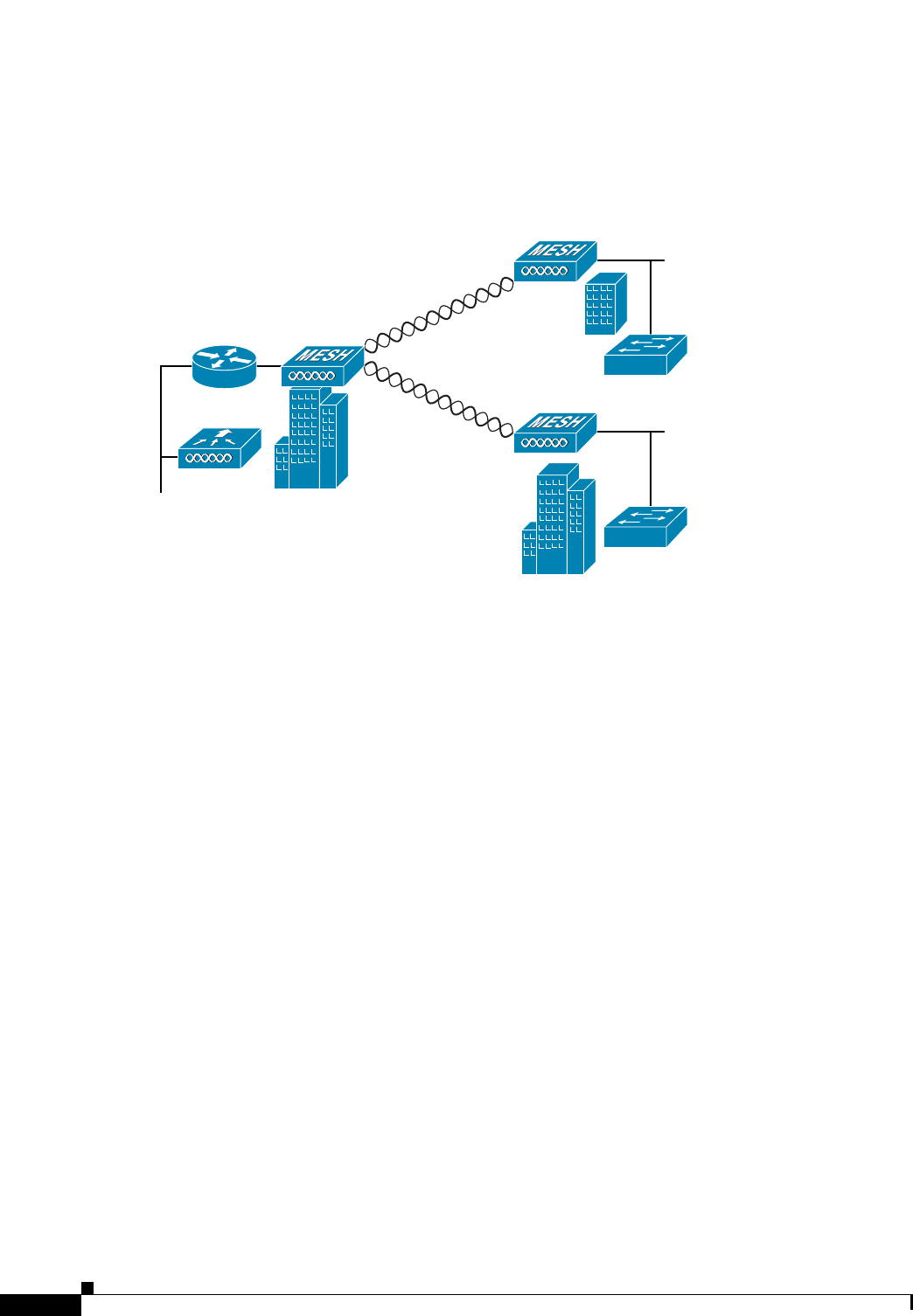
Bridging
The access points can be used as a RAP to connect multiple remote MAPs with their associated wired
networks (see Figure 4). By default this capability is turned-off for all access points. To support
Ethernet bridging, you must enable bridging on the controller for each access point.
Wireless client access can be provided over the bridging link; however, if bridging between tall
buildings, the 2.4-Ghz wireless coverage area may be limited and possibly not suitable for direct
wireless client access.
Figure 4 Access Point Point to Multipoint Bridging Example
Mesh Network
The access points are typically deployed in a mesh network configuration. In a typical mesh
deployment, one or more RAPs have a wired network connection through a switch to a controller. Other
remote MAPs without wired network connections use the backhaul feature to optimally link to a RAP
that is connected to the wired network. In the mesh network, the links between the access points are
referred to as the backhaul links.
Intelligent wireless routing is provided by the patent-pending Adaptive Wireless Path protocol (AWPP).
This enables each MAP to identify its neighbors and intelligently choose the optimal path to the RAP
with the wired network connection by calculating the cost of each path in terms of signal strength and
the number of hops required to get to a controller.
148439
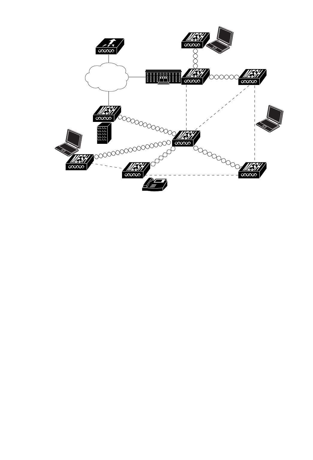
Figure 5 illustrates a typical mesh configuration using MAPs and RAPs.
Figure 5 Typical Mesh Configuration Using Access Points
155631
IP
10
Overview
OL-12632-01
Layer
2
and
Layer
3
Network
Operation
The access points support Layer 2 or Layer 3 network operation. In Layer 2 configurations, the access
point and the controller are on the same subnet and communicate with encapsulated Ethernet frames
using MAC addresses rather than IP addresses. Layer 2 configurations are typically not scalable into
larger networks. Additionally, Layer 2 operation is supported only by the Cisco 4400 series controllers.
Access points and controllers in Layer 3 configurations use IP addresses and UDP packets, which can
be routed through large networks. Layer 3 operation is scalable and recommended by Cisco.
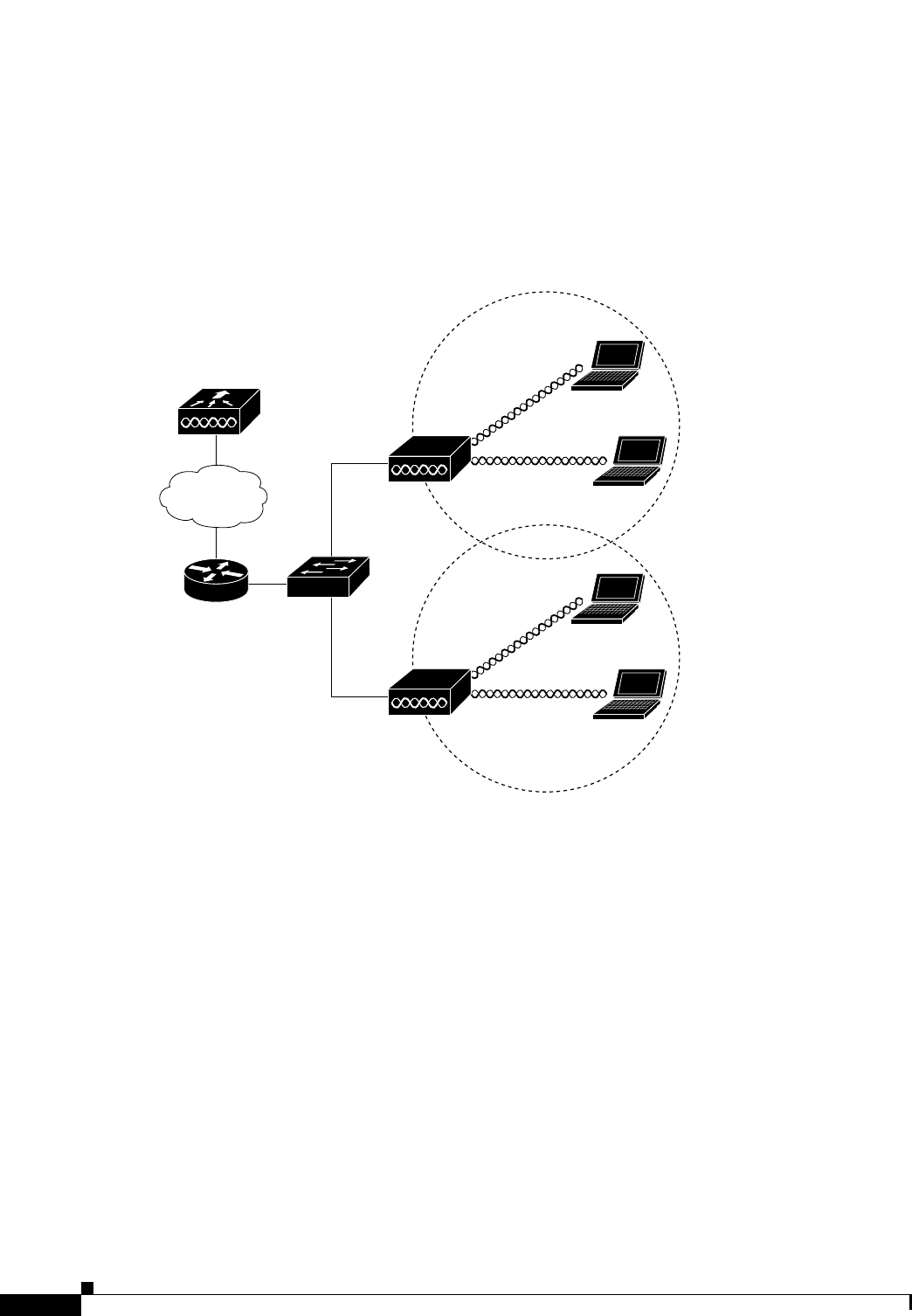
Figure 6 illustrates a typical Layer-3 wireless network configuration containing access points and a
controller.
Figure 6 Typical Layer 3 Access Point Network Configuration Example
1
58085
LWAPP
LWAPP
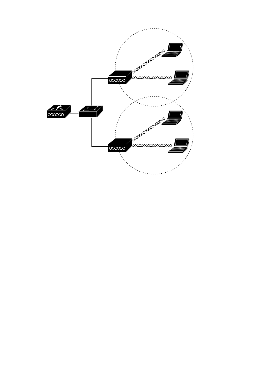
Figure 7 illustrates a typical Layer 2 network configuration. In a Layer 2 configuration, the controller
and the access points are on the same subnet.
Figure 7 Typical Layer 2 Access Point Network Configuration Example
1
58084
LWAPP
LWAPP

12
Overview
OL-12632-01

CISCO CONFIDENTIAL - Draft 1
B-1
Cisco Aironet 1520 Series Outdoor Mesh Access Point Hardware Installation Guide
OL-12632-01
APPENDIX
B
Declarations of Conformity and
Regulatory Information
This appendix provides declarations of conformity and regulatory information for the
Cisco Aironet 1520 series lightweight outdoor mesh access point.
This appendix contains the following sections:
•Manufacturers Federal Communication Commission Declaration of Conformity Statement, page 2
•Department of Communications—Canada, page 3
•Declaration of Conformity for RF Exposure, page 3
•Administrative Rules for Cisco Aironet Access Points in Taiwan, page 4

2
OL-12632-01
Manufacturers
Federal
Communication
Commission
Declaration of Conformity Statement
Model:
AIR-LAP1522AG-A-K9
AIR-LAP1521G-A-K9
FCC Certification number:
Manufacturer:
Cisco Systems, Inc.
170 West Tasman Drive
San Jose, CA 95134-1706
USA
This device complies with Part 15 rules. Operation is subject to the following two conditions:
1. This device may not cause harmful interference, and
2. This device must accept any interference received, including interference that may cause undesired
operation.
This equipment has been tested and found to comply with the limits of a Class B digital device, pursuant
to Part 15 of the FCC Rules. These limits are designed to provide reasonable protection against harmful
interference when the equipment is operated in a residential environment. This equipment generates,
uses, and radiates radio frequency energy, and if not installed and used in accordance with the
instructions, may cause harmful interference. However, there is no guarantee that interference will not
occur. If this equipment does cause interference to radio or television reception, which can be
determined by turning the equipment off and on, the user is encouraged to correct the interference by
one of the following measures:
•Reorient or relocate the receiving antenna.
•Increase separation between the equipment and receiver.
•Connect the equipment to an outlet on a circuit different from which the receiver is connected.
•Consult the dealer or an experienced radio/TV technician.
Caution The Part 15 radio device operates on a non-interference basis with other devices operating
at this frequency when using Cisco-supplied antennas. Any changes or modification to the
product not expressly approved by Cisco could void the user’s authority to operate this
device.
Caution To meet regulatory restrictions, the access point must be professionally installed.
Tested To Comply
With FCC Standard
s
FOR HOME OR OFFICE USE
AIR-RM1520G-A-K9: LDK102064
AIR-RM1520A-A-K9: LDK102063
Note The use of the 4.9-GHz band requires a license and may be used only by qualified Public Safety
operators as defined in section 90.20 of the FCC rules ( LAP1510 model only).
VCCI Statement for Japan
Department of Communications—Canada
IC Certification Number:
Canadian Compliance Statement
This Class B Digital apparatus meets all the requirements of the Canadian Interference-Causing
Equipment Regulations.
Cet appareil numerique de la classe B respecte les exigences du Reglement sur le material broilleur du
Canada.
This device complies with Class B Limits of Industry Canada. Operation is subject to the following two
conditions:
1. This device may not cause harmful interference, and
2. This device must accept any interference received, including interference that may cause undesired
operation.
Cisco’s access points are certified to the requirements of RSS-210 issue 5, RSP 100, and RSS 102 for
spread spectrum devices.
Declaration of Conformity for RF Exposure
This access point product has been found to be compliant to the requirements set forth in CFR 47
Section 1.1307 addressing RF Exposure from radio frequency devices as defined in Evaluating
Compliance with FCC Guidelines for Human Exposure to Radio Frequency Electromagnetic Fields.T
he antennas should be positioned more than 6.56 feet (2 meters) from your body or nearby persons.
This access point is also compliant to EN 50835 for RF exposure.
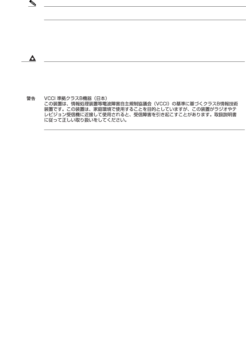
Warning
This is a Class B product based on the standard of the Voluntary Control Council for Interference from
Information Technology Equipment (VCCI). If this is used near a radio or television receiver in a
domestic environment, it may cause radio interference. Install and use the equipment according to
the instruction manual.
AIR-RM1520G-A-K9: 2461B-102064
AIR-RM1520A-A-K9: 2461B-102063
4
OL-12632-01
Administrative
Rules
for
Cisco
Aironet
Access
Points
in
Taiwan
This section provides administrative rules for operating Cisco Aironet access points in Taiwan. The
rules are provided in both Chinese and English.
Chinese Translation

English
Translation
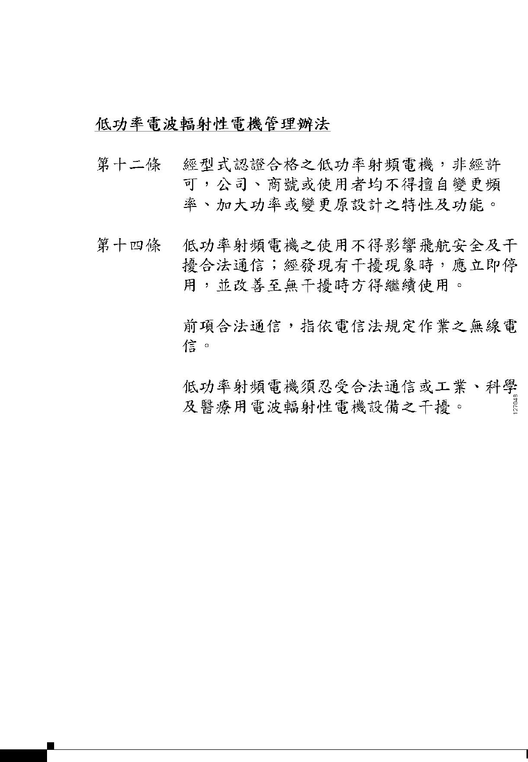
Administrative Rules for Low-power Radio-Frequency Devices
Article 12
For those low-power radio-frequency devices that have already received a type-approval, companies,
business units or users should not change its frequencies, increase its power or change its original
features and functions.
Article 14
The operation of the low-power radio-frequency devices is subject to the conditions that no harmful
interference is caused to aviation safety and authorized radio station; and if interference is caused, the
user must stop operating the device immediately and can't re-operate it until the harmful interference is
clear.
The authorized radio station means a radio-communication service operating in accordance with the
Communication Act.
The operation of the low-power radio-frequency devices is subject to the interference caused by the
operation of an authorized radio station, by another intentional or unintentional radiator, by industrial,
scientific and medical (ISM) equipment, or by an incidental radiator.

6
OL-12632-01

CHAPTER
CISCO CONFIDENTIAL - Draft 1
7-1
Channels and Maximum Power Settings for Cisco Aironet Lightweight Access Points
OL-xxxxx-01
7
Cisco Aironet 1520 Series Mesh Access Points
This chapter lists the 1520 series mesh access point IEEE 802.11b/g (2.4-GHz) and IEEE 802.11a
(5-GHz) channels and the maximum power levels supported by the world’s regulatory domains. For
additional product hardware information refer to the Cisco Aironet 1520 Series Outdoor Mesh Access
Point Hardware Installation Guide.
The AIR-LAP1522 access point model supports both 802.11b/g and 802.11a radios, The AIR-LAP1521
access point model only supports a 802.11b/g radio.
The following topics are covered in this chapter:
•Channels and Maximum Power Levels, page 7-2
•Special Country Restrictions, page 7-5
•Special Country Restrictions, page 7-5

CISCO CONFIDENTIAL - Draft 1
7-2
Channels and Maximum Power Settings for Cisco Aironet Lightweight Access Points
OL-xxxxx-01
Chapter 7 Cisco Aironet 1520 Series Mesh Access Points
Channels and Maximum Power Levels
Channels and Maximum Power Levels
IEEE 802.11b/g (2.4-GHz Band)
When shipped from the factory, theAIR-LAP1522G access points support the channels and maximum
power levels listed in Table 7-1 for their regulatory domain.
Note In Table 7-1, the operating data rates (in Mbps) are shown in the CCK and OFDM table cells. For
example: CCK 1-11 indicates CCK data rates of 1 to 11 Mbps and All indicates all CCK and OFDM data
rates.
Table 7-1 Channels and Maximum Conducted Power for the 802.11b/g Radio with Up to
5.5-dBi Antennas
Channel
ID
Center
Freq
(MHz)
Maximum Conducted Power
Levels (dBm) in the Regulatory
Domains
–A
CCK
1-11
OFDM
6-48
OFDM
54
12412282525
22417282626
32422282726
42427282726
52432282726
62437282726
72442282726
82447282726
92452282726
10 2457 28 26 26
11 2462 28 25 25
12 2467 – – –
13 2472 – – –
14 2484 – – –

CISCO CONFIDENTIAL - Draft 1
7-3
Channels and Maximum Power Settings for Cisco Aironet Lightweight Access Points
OL-xxxxx-01
Chapter 7 Cisco Aironet 1520 Series Mesh Access Points
Channels and Maximum Power Levels
Table 7-2 Channels and Maximum Conducted Power for the 802.11b/g Radio with Up to
8.0-dBi Antennas
Channel
ID
Center
Freq
(MHz)
Maximum Conducted Power
Levels (dBm) in the Regulatory
Domains
–A
CCK
1-11
OFDM
6-48
OFDM
54
12412282424
22417282525
32422282626
42427282726
52432282726
62437282726
72442282726
82447282726
92452282626
10 2457 28 25 25
11 2462 28 24 24
12 2467 – – –
13 2472 – – –
14 2484 – – –

CISCO CONFIDENTIAL - Draft 1
7-4
Channels and Maximum Power Settings for Cisco Aironet Lightweight Access Points
OL-xxxxx-01
Chapter 7 Cisco Aironet 1520 Series Mesh Access Points
Channels and Maximum Power Levels
IEEE 802.11a (5-GHz Band)
When shipped from the factory, the AIR-LAP1522AG access points support the channels and maximum
power levels listed in Table 7-4 for their regulatory domain.
Note In Table 7-4, the operating data rates (in Mbps) are shown in the OFDM table cells. For example: OFDM
6-36 indicates 6 to 36 Mbps data rates.
Table 7-3 Channels and Maximum Conducted Power for IEEE 802.11a Radio with Up to 17 dBi Antennas
Channel
ID
Center
Frequency
(MHz)
Bandwidth
(MHz)
Maximum Conducted Power Levels (dBm) in the Regulatory Domains
–A –N –T
OFDM
6-36
OFDM
48
OFDM
54
OFDM
6-36
OFDM
48
OFDM
54
OFDM
6-36
OFDM
48
OFDM
54
(4900 to 5100 MHz)
20 4950 20 20 20 20 ––––––
21 4955 20 20 20 20 ––––––
22 4960 20 20 20 20 ––––––
23 4965 20 20 20 20 ––––––
24 4970 20 20 20 20 ––––––
25 5975 20 20 20 20 ––––––
26 4980 20 20 20 20 ––––––
5725 to 5850 MHz
149 5745 20 28 27 26 28 27 26 28 27 26
153 5765 20 28 27 26 28 27 26 28 27 26
157 5785 20 28 27 26 28 27 26 28 27 26
161 5805 20 28 27 26 28 27 26 28 27 26
165 5825 20 28 27 26 28 27 26 28 27 26

CISCO CONFIDENTIAL - Draft 1
7-5
Channels and Maximum Power Settings for Cisco Aironet Lightweight Access Points
OL-xxxxx-01
Chapter 7 Cisco Aironet 1520 Series Mesh Access Points
Channels and Maximum Power Levels
Special Country Restrictions
Table 7-4 lists special restrictions for wireless operation in some countries.
Table 7-4 Special Country Restrictions for Wireless Operation
Country
Frequency
Band (GHz)
Regulatory
Domain Special Limitation and Restrictions
Australia 5 –N 5 GHz maximum antenna gain limited to 7 dBi.
Mexico 2.4 –N End user must limit 2.4 GHz operation to 2450 to 2483.5 MHz and 36
dBm EIRP1.
1. EIRP (dBm) = maximum output power (dBm) + antenna gain (dBi)
New Zealand 5 –N 5 GHz maximum antenna gain limited to 7 dBi.
United States 4.9 –A The use of the 4.9-GHz band requires a license and may be used only
by qualified Public Safety operators as defined in section 90.20 of the
FCC rules.

CISCO CONFIDENTIAL - Draft 1
7-6
Channels and Maximum Power Settings for Cisco Aironet Lightweight Access Points
OL-xxxxx-01
Chapter 7 Cisco Aironet 1520 Series Mesh Access Points
Changing the Lightweight Access Point Output Power
Changing the Lightweight Access Point Output Power
This section provides instructions for changing the 1500 series access point output power to comply with
the maximum power limits imposed by special regulatory and country restrictions (see the “Special
Country Restrictions” section on page 7-5). Follow these instructions to change the output power
settings using a controller and your browser:
Note Administrator privileges may be required in order to change access point settings.
Caution To meet regulatory restrictions, the access point and the external antenna must be professionally
installed. The network administration or other IT professional responsible for installing and configuring the
unit is a suitable professional installer. Following installation, access to the unit should be
password-protected by the network administrator to maintain regulatory compliance.
The output power on the 1500 series access points can be changed only by using a Cisco wireless LAN
controller (2600 series or 4400 series), the controllers on a Cisco Wireless Services Module (WiSM), or
using Cisco Wireless Control System (WCS).
Note See the Cisco Wireless LAN Controller Configuration Guide for more details on how to to configure your
access point using the web-browser interface.
Follow these steps to change the 1500 series access point’s output power to meet local regulations using
a controller:
Step 1 Open your Internet browser. You must use Microsoft Internet Explorer 6.0.2800 or a later release.
Step 2 Enter https://IP address (where IP address is the controller’s IP address) in the browser address line
and press Enter. A user login screen appears.
Step 3 Enter the username and password and press Enter. The controller’s summary page appears.
Note The username and password are case-sensitive.
Step 4 Click Wireless > 802.11a Radios or 802.11b/g Radios and a list of associated access points appears.
Step 5 Choose the desired access point from the displayed list and click Configure. The the radio settings page
appears.
Step 6 Scroll down to the Tx Power Level Assignment field, and click Custom.
Custom indicates that the radio output power is manually controlled by the Tx Power Configuration
setting field.

CISCO CONFIDENTIAL - Draft 1
7-7
Channels and Maximum Power Settings for Cisco Aironet Lightweight Access Points
OL-xxxxx-01
Chapter 7 Cisco Aironet 1520 Series Mesh Access Points
Changing the Lightweight Access Point Output Power
Step 7 In the Tx Power Level field, select the appropriate power level setting (1 to 5).
Based on the operating channel, the regulatory domain, and the controller power level setting (1 to 5),
the actual transmit power at the access point can be reduced to comply with special regulatory or country
restrictions.
Note The access point supports only two output power levels for the 2.4-GHz radio and three output
power levels for the 5-GHz radio.
Note Table 7-1 and Table 7-3 list the access point maximum output power levels supported for each
regulatory domain when the access point is shipped from the factory.
Table 7-5 lists the controller power settings and the corresponding output power levels for these two
examples:
•2.4-GHz (802.11b/g) operation:
–
American regulatory domain
–
Channel 3 using 11-Mbps data rates
•5-GHz (802.11a) operation:
–
American regulatory domain
–
Channel 149 using 36-Mbps data rates
Step 8 Click Apply.
Step 9 Close your Internet browser.
For additional configuration information, refer to the Cisco Wireless LAN Controller Configuration
Guide.
Table 7-5 Example of Output Power Levels
Controller
Tx Power Settings1
1. The Tx Power Level setting of 1 represents the maximum conducted power
setting for the access point. Each subsequent controller power level (such as
2, 3, 4, etc.) represents an approximate 3-dBm reduction in transmit power
from the previous power level.
Radio Output Power
802.11b/g
(dBm) 802.11a (dBm)
1 (maximum) 242
2. The maximum output power level obtained from Table 7-1.
243
3. The maximum output power level obtained from Table 7-3.
22121

CISCO CONFIDENTIAL - Draft 1
7-8
Channels and Maximum Power Settings for Cisco Aironet Lightweight Access Points
OL-xxxxx-01
Chapter 7 Cisco Aironet 1520 Series Mesh Access Points
Changing the Lightweight Access Point Output Power