Cisco Systems 102067 4.9GHz Radio Module User Manual 1520higb
Cisco Systems Inc 4.9GHz Radio Module 1520higb
UserManual.wiki
>
Cisco Systems
>
102067 User Manual
>
Manual 1
Contents
1.
Manual 1
2.
Manual 2
3.
Manual 3
Manual 1
Navigation menu
Upload a User Manual
Namespaces
Wiki Guide
HTML
PDF
Info
Views
User Manual
Discussion / Help
Navigation
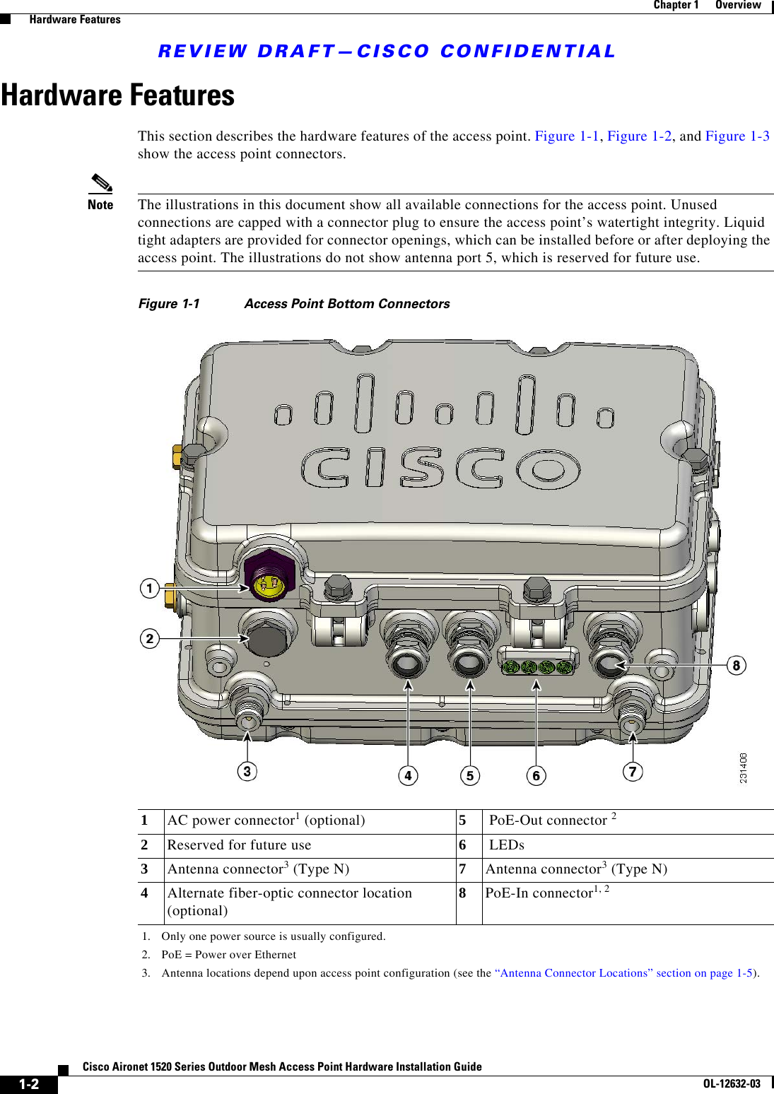
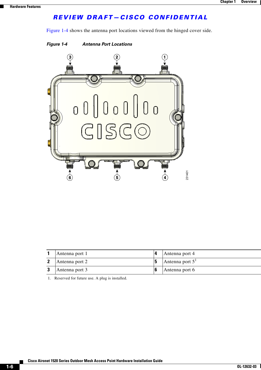

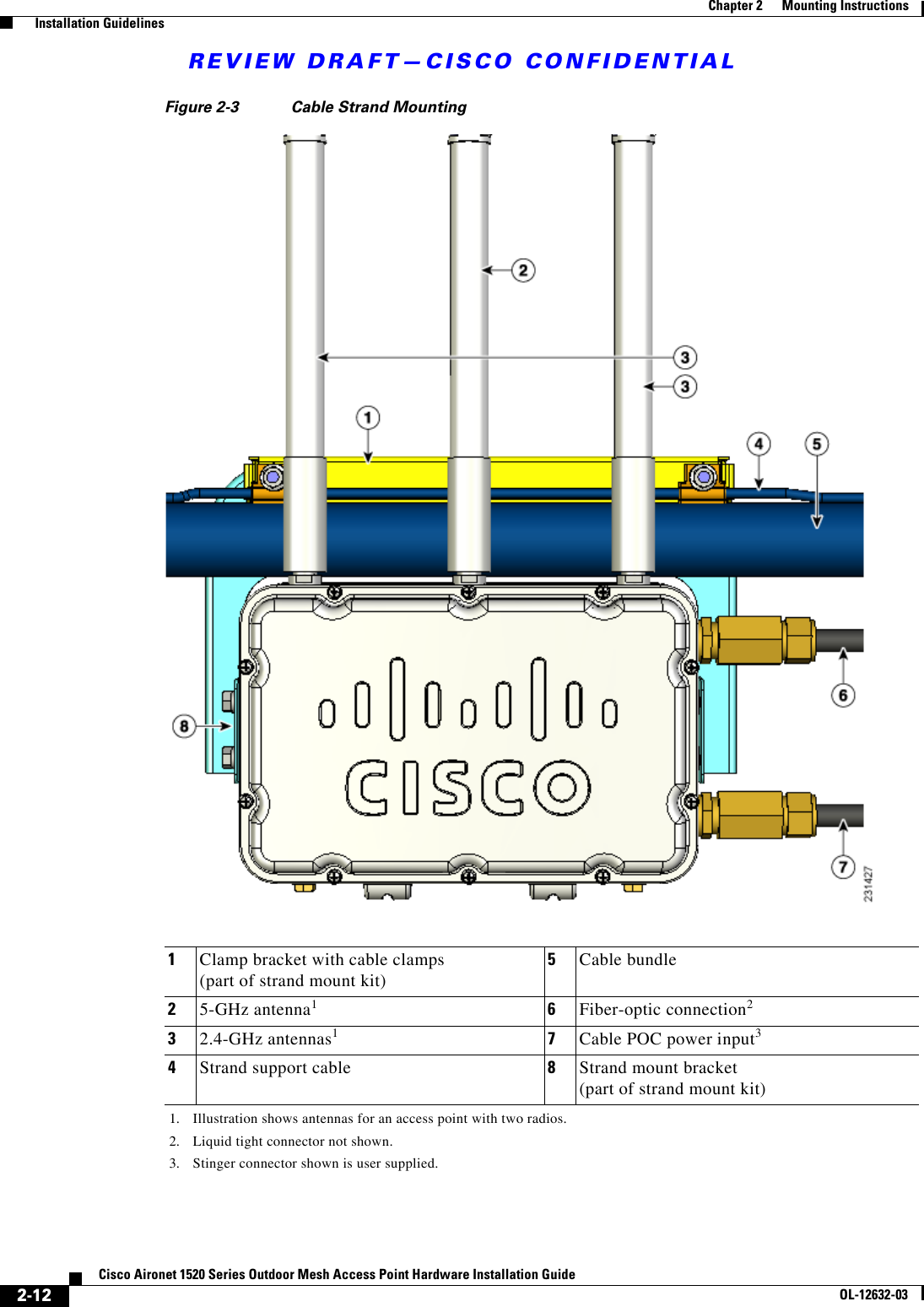
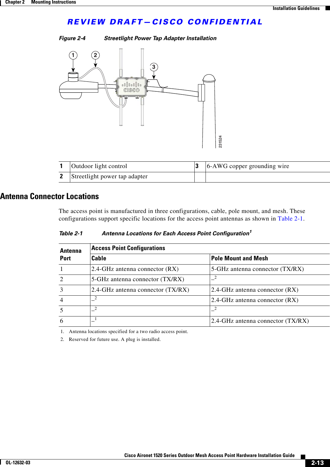
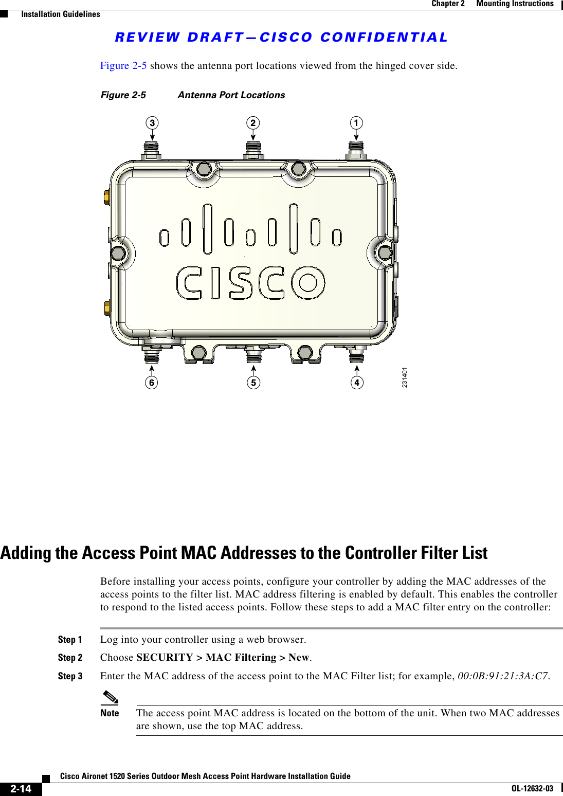
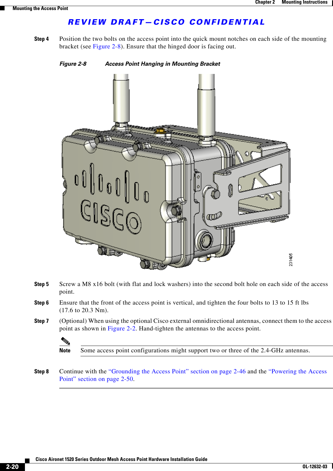
![REVIEW DRAFT—CISCO CONFIDENTIAL2-7Cisco Aironet 1520 Series Outdoor Mesh Access Point Hardware Installation GuideOL-12632-03Chapter 2 Mounting Instructions Avoiding Damage to Radios in a Testing EnvironmentAvoiding Damage to Radios in a Testing EnvironmentThe radios on outdoor units (bridges) have higher transmit power levels than radios on indoor units (access points). When you test high power radios in a link, you must avoid exceeding the receiver’s maximum receive input level. At levels above the normal operating range, packet error rate (PER) performance is degraded. At even higher levels, the receiver can be permanently damaged. To avoid receiver damage and PER degradation, you can use one of the following techniques: • Separate the omnidirectional antennas by at least 2 ft (0.6 m) to avoid receiver damage or by at least 25 ft (7.6 m) to avoid PER degradation.Note These distances assume free space path loss and are conservative estimates. Required separation distances for damage and performance degradation levels in actual deployments are less if conditions are not non line-of-sight. • Reduce the configured transmit power to the minimum level. • Use directional antennas, and keep them away from each other. • Cable the radios together using a combination of attenuators, combiners, or splitters to achieve a total attenuation of at least 60 dB.For a radiated test bed, the following equation describes the relationships among transmit power, antenna gain, attenuation, and receiver sensitivity:txpwr + tx gain + rx gain - [attenuation due to antenna spacing] < max rx input levelWhere:txpwr = Radio transmit power leveltx gain = transmitter antenna gainrx gain = receiver antenna gainFor a conducted test bed, the following equation describes the relationships among transmit power, antenna gain, and receiver sensitivity:txpwr - [attenuation due to coaxial components] < max rx input levelCaution Under no circumstances should you connect the antenna port from one access point to the antenna port of another access point without using an RF attenuator. If you connect antenna ports, you must not exceed the maximum survivable receive level of 0 dBm. Never exceed 0 dBm, or damage to the access point can occur. Using attenuators, combiners, and splitters having a total of at least 60 dB of attenuation ensures that the receiver is not damaged and that PER performance is not degraded.](https://usermanual.wiki/Cisco-Systems/102067.Manual-1/User-Guide-897134-Page-37.png)