Cisco Systems 102075P Cisco Aironet 802.11n DualBand Access Points User Manual ap3602pgetstart
Cisco Systems Inc Cisco Aironet 802.11n DualBand Access Points ap3602pgetstart
Manual

GETTING STARTED GUIDE
Cisco Aironet 3602P Lightweight Access Points
1About this Guide
2Safety Instructions
3Unpacking
4Configurations
5Access Point Ports and Connectors
6Configuring the Access Point
7Mounting the Access Point
8Deploying the Access Point on the Wireless Network
9Troubleshooting
10 Declarations of Conformity and Regulatory Information
11 Configuring DHCP Option 43 and DHCP Option 60
12 Access Point Specifications
ap3602pgetstart.fm Page 1 Friday, September 21, 2012 10:28 AM

2
1 About this Guide
This Guide provides instructions on how to install and configure your Cisco Aironet 3602P Access
Point. This guide also provides mounting instructions and limited troubleshooting procedures.
The 3602P Access Point is referred to as the access point in this document.
2 Safety Instructions
Translated versions of the following safety warnings are provided in the translated safety warnings
document that is shipped with your access point. The translated warnings are also in the Translated
Safety Warnings for Cisco Aironet Access Points, which is available on Cisco.com.
Warning
IMPORTANT SAFETY INSTRUCTIONS
This warning symbol means danger. You are in a situation that could cause bodily injury.
Before you work on any equipment, be aware of the hazards involved with electrical
circuitry and be familiar with standard practices for preventing accidents. Use the
statement number provided at the end of each warning to locate its translation in the
translated safety warnings that accompanied this device.
Statement 1071
SAVE THESE INSTRUCTIONS
Warning
Only trained and qualified personnel should be allowed to install, replace, or service this
equipment.
Statement 1030
Warning
In order to comply with radio frequency (RF) exposure limits, the antennas for this
product should be positioned no less than 6.56 ft (2 m) from your body or nearby persons.
Statement 339
Warning
Read the installation instructions before you connect the system to its power source.
Statement 1004
ap3602pgetstart.fm Page 2 Friday, September 21, 2012 10:28 AM

3
Warning
This product must be connected to a Power-over-Ethernet (PoE) IEEE 802.3af compliant
power source or an IEC60950 compliant limited power source.
Statement 353
Warning
Installation of the equipment must comply with local and national electrical codes.
Statement 1074
Warning
This product relies on the building’s installation for short-circuit (overcurrent)
protection. Ensure that the protective device is rated not greater than:
20A.
Statement 1005
Warning
Do not operate your wireless network device near unshielded blasting caps or in an
explosive environment unless the device has been modified to be especially qualified for
such use.
Statement 245B
Caution The fasteners you use to mount an access point on a ceiling must be capable of
maintaining a minimum pullout force of 20 lbs (9 kg) and must use all 4 indented holes
on the mounting bracket.
Caution This product and all interconnected equipment must be installed indoors within the same
building, including the associated LAN connections as defined by Environment A of the
IEEE 802.af Standard.
Note The access point is suitable for use in environmental air space in accordance with section
300.22.C of the National Electrical Code and sections 2-128, 12-010(3), and 12-100 of the
Canadian Electrical Code, Part 1, C22.1. You should not install the power supply or power
injector in air handling spaces.
Note Use only with listed ITE equipment.
ap3602pgetstart.fm Page 3 Friday, September 21, 2012 10:28 AM

4
3 Unpacking
To unpack the access point, follow these steps:
Step 1 Unpack and remove the access point and the accessory kit from the shipping box.
Step 2 Return any packing material to the shipping container and save it for future use.
Step 3 Verify that you have received the items listed below. If any item is missing or damaged, contact
your Cisco representative or reseller for instructions.
–
The access point
–
Mounting bracket (optional; selected when you ordered the access point)
–
Adjustable ceiling-rail clip (optional; selected when you ordered the access point)
4 Configurations
The 3602P access point contains two simultaneous dual-band radios, the 2.4-GHz and 5-GHz 802.11n
MIMO radios. For information on the regulatory domains (shown as “x” in the model numbers) see
“Countries Supported” section on page 5.
External Antennas
The 3602P access point is configured with up to four external antennas and two 2.4-GHz/ 5-GHz
dual-band radios. The radio and antennas support frequency bands 2400–2500 MHz and 5150–5850
MHz through a common dual-band RF interface. Features of the external dual-band dipole antennas
are:
•Four RTNC antenna connectors on the top of the access point
•Four TX/RX antennas
These antennas are supported on the 3602P:
•AIR-ANT2524DB-R
•AIR-ANT2524DW-R
•AIR-ANT2524DG-R
•AIR-ANT2524V4C-R
•AIR-ANT2546V4M-R
•AIR-ANT2566P4W-R
ap3602pgetstart.fm Page 4 Friday, September 21, 2012 10:28 AM
5
Countries Supported
Click this URL to browse to a list of countries and regulatory domains supported by the 3600:
www.cisco.com/go/aironet/compliance
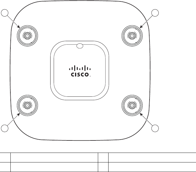
5 Access Point Ports and Connectors
The 3602P access point has external antenna connectors and the LED indictor on the top of the model,
as shown in Figure 1.
Figure 1 Access Point Ports and Connections (top)—3602E Model
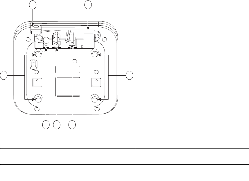
The ports and connections on the bottom of the access point are shown in Figure 2.
1Dual-band antenna connector A 3Dual-band antenna connector C
2Dual-band antenna connector B 4Dual-band antenna connector D
A
D
U
A
L
B
A
N
D
B
D
U
A
L
B
A
N
D
C
D
U
A
L
B
A
N
D
D
D
U
A
L
B
A
N
D
1
4
2
3
ap3602pgetstart.fm Page 5 Friday, September 21, 2012 10:28 AM
6
Figure 2 Access Point Ports and Connections (bottom)
6 Configuring the Access Point
This section describes how to connect the access point to a wireless LAN controller. Because the
configuration process takes place on the controller, see the Cisco Wireless LAN Controller
Configuration Guide for additional information. This guide is available on Cisco.com.
The Controller Discovery Process
The access point uses standard Control and Provisioning of Wireless Access Points Protocol
(CAPWAP) to communicate between the controller and other wireless access points on the network.
CAPWAP is a standard, interoperable protocol which enables an access controller to manage a
1Kensington lock slot 4Console port
2
DC Power connection
5
Security padlock and hasp (padlock not
included)
3Gbit Ethernet port 6Mounting bracket pins (feet for desk or
table-top mount)
272377
2 3 4
1 5
6 6
ap3602pgetstart.fm Page 6 Friday, September 21, 2012 10:28 AM

7
collection of wireless termination points. The discovery process using CAPWAP is identical to the
Lightweight Access Point Protocol (LWAPP) used with previous Cisco Aironet access points.
LWAPP-enabled access points are compatible with CAPWAP, and conversion to a CAPWAP controller
is seamless. Deployments can combine CAPWAP and LWAPP software on the controllers.
The functionality provided by the controller does not change except for customers who have Layer 2
deployments, which CAPWAP does not support.
In a CAPWAP environment, a wireless access point discovers a controller by using CAPWAP discovery
mechanisms and then sends it a CAPWAP join request. The controller sends the access point a
CAPWAP join response allowing the access point to join the controller. When the access point joins
the controller, the controller manages its configuration, firmware, control transactions, and data
transactions.
Note For additional information about the discovery process and CAPWAP, see the Cisco Wireless
LAN Controller Software Configuration Guide. This document is available on Cisco.com.
Note CAPWAP support is provided in controller software release 5.2 or later. However, your
controller must be running release 7.1.91.0 or later to support 3600 series access points.
Note You cannot edit or query any access point using the controller CLI if the name of the access
point contains a space.
Note Make sure that the controller is set to the current time. If the controller is set to a time that
has already occurred, the access point might not join the controller because its certificate may
not be valid for that time.
Access points must be discovered by a controller before they can become an active part of the network.
The access point supports these controller discovery processes:
•Layer 3 CAPWAP discovery—Can occur on different subnets than the access point and uses IP
addresses and UDP packets rather than MAC addresses used by Layer 2 discovery.
•Locally stored controller IP address discovery—If the access point was previously joined to a
controller, the IP addresses of the primary, secondary, and tertiary controllers are stored in the
access point’s non-volatile memory. This process of storing controller IP addresses on an access
point for later deployment is called priming the access point. For more information about priming,
see the “Performing a Pre-Installation Configuration” section on page 9.
ap3602pgetstart.fm Page 7 Friday, September 21, 2012 10:28 AM

8
•DHCP server discovery—This feature uses DHCP option 43 to provide controller IP addresses to
the access points. Cisco switches support a DHCP server option that is typically used for this
capability. For more information about DHCP option 43, see the “Configuring DHCP Option 43
and DHCP Option 60” section on page 20.
•DNS discovery—The access point can discover controllers through your domain name server
(DNS). For the access point to do so, you must configure your DNS to return controller IP
addresses in response to CISCO-CAPWAP-CONTROLLER.localdomain, where localdomain is
the access point domain name. Configuring the CISCO-CAPWAP-CONTROLLER provides
backwards compatibility in an existing customer deployment. When an access point receives an IP
address and DNS information from a DHCP server, it contacts the DNS to resolve
CISCO-CAPWAP-CONTROLLER.localdomain. When the DNS sends a list of controller IP
addresses, the access point sends discovery requests to the controllers.
Preparing the Access Point
Before you mount and deploy your access point, we recommend that you perform a site survey (or use
the site planning tool) to determine the best location to install your access point.
You should have the following information about your wireless network available:
•Access point locations.
•Access point mounting options: below a suspended ceiling, on a flat horizontal surface, or on a
desktop.
Note You can mount the access point above a suspended ceiling but you must purchase
additional mounting hardware: See “Mounting the Access Point” section on page 13 for
additional information.
•Access point power options: power supplied by the recommended external power supply (Cisco
AIR-PWR-B), a DC power supply, PoE from a network device, or a PoE power injector/hub
(usually located in a wiring closet).
Note Access points mounted in a building’s environmental airspace must be powered using PoE
to comply with safety regulations.
Cisco recommends that you make a site map showing access point locations so that you can record the
device MAC addresses from each location and return them to the person who is planning or managing
your wireless network.
ap3602pgetstart.fm Page 8 Friday, September 21, 2012 10:28 AM

9
Installation Summary
Installing the access point involves these operations:
•Performing a pre-installation configuration (optional)
•Mounting the access point
•Grounding the access point
•Deploying the access point on the wireless network
Performing a Pre-Installation Configuration
The following procedures ensure that your access point installation and initial operation go as
expected. A pre-installation configuration is also known as priming the access point. This procedure
is optional.
Note Performing a pre-installation configuration is an optional procedure. If your network
controller is properly configured, you can install your access point in its final location and
connect it to the network from there. See the “Deploying the Access Point on the Wireless
Network” section on page 13 for details.
Pre-Installation Configuration Setup
The pre-installation configuration setup is shown in Figure 3.
ap3602pgetstart.fm Page 9 Friday, September 21, 2012 10:28 AM
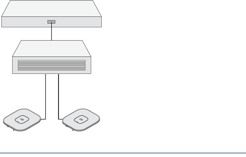
10
Figure 3 Pre-Installation Configuration Setup
To perform pre-installation configuration, perform the following steps:
Step 1 Make sure that the Cisco wireless LAN controller DS port is connected to the network. Use
the CLI, web-browser interface, or Cisco WCS procedures as described in the appropriate
Cisco wireless LAN controller guide.
a. Make sure that access points have Layer 3 connectivity to the Cisco wireless LAN controller
Management and AP-Manager Interface.
b. Configure the switch to which your access point is to attach. See the Cisco Wireless LAN
Controller Configuration Guide, Release x.x for additional information.
c. Set the Cisco wireless LAN controller as the master so that new access points always join with
it.
d. Make sure DHCP is enabled on the network. The access point must receive its IP address
through DHCP.
e. CAPWAP UDP ports must not be blocked in the network.
Controller
Layer 3
devices
Cisco Aironet
access points
272488
ap3602pgetstart.fm Page 10 Friday, September 21, 2012 10:28 AM

11
f. The access point must be able to find the IP address of the controller. This can be
accomplished using DHCP, DNS, or IP subnet broadcast. This guide describes the DHCP
method to convey the controller IP address. For other methods, refer to the product
documentation. See also the “Using DHCP Option 43” section on page 14 for more
information.
Step 2 Apply power to the access point:
a. The access point is 802.3af (15.4 W) compliant and can be powered by any of the following
802.3af compliant devices:
–
2106 controller
–
WS-C3550, WS-C3560, and WS-C3750 switches
–
C1880 switch
–
2600, 2610, 2611, 2621, 2650, and 2651 multiservice platforms
–
2610XM, 2611XM, 2621XM, 2650XM, 2651XM, and 2691 multiservice platforms
–
2811, 2821, and 2851 integrated services routers
–
3620, 3631-telco, 3640, and 3660 multiservice platforms
–
3725 and 3745 multiservice access routers
–
3825 and 3845 integrated services routers
The recommended external power supply for the access point is the Cisco AIR-PWR-B
power supply. The access point can also be powered by the following optional external
power sources:
–
AIR-PWRINJ4 or AIR-PWRINJ5 power injectors
–
Any 802.3af compliant power injector
Note The 3602P access point requires a Gigibit Ethernet link to prevent the Ethernet port
from becoming a bottleneck for traffic because wireless traffic speeds exceed transmit
speeds of a 10/100 Ethernet port.
b. As the access point attempts to connect to the controller, the LEDs cycle through a green, red,
and amber sequence, which can take up to 5 minutes.
Note If the access point remains in this mode for more than five minutes, the access point is
unable to find the Master Cisco wireless LAN controller. Check the connection between
the access point and the Cisco wireless LAN controller and be sure that they are on the
same subnet.
c. If the access point shuts down, check the power source.
ap3602pgetstart.fm Page 11 Friday, September 21, 2012 10:28 AM

12
d. After the access point finds the Cisco wireless LAN controller, it attempts to download the
new operating system code if the access point code version differs from the Cisco wireless
LAN controller code version. While this is happening, the Status LED blinks dark blue.
e. If the operating system download is successful, the access point reboots.
Step 3 Configure the access point if required. Use the controller CLI, controller GUI, or Cisco WCS
to customize the access-point-specific 802.11n network settings.
Step 4 If the pre-installation configuration is successful, the Status LED is green indicating normal
operation. Disconnect the access point and mount it at the location at which you intend to
deploy it on the wireless network.
Step 5 If your access point does not indicate normal operation, turn it off and repeat the
pre-installation configuration.
Note When you are installing a Layer 3 access point on a different subnet than the Cisco
wireless LAN controller, be sure that a DHCP server is reachable from the subnet on
which you will be installing the access point, and that the subnet has a route back to
the Cisco wireless LAN controller. Also be sure that the route back to the Cisco
wireless LAN controller has destination UDP ports 5246 and 5247 open for CAPWAP
communications. Ensure that the route back to the primary, secondary, and tertiary
wireless LAN controller allows IP packet fragments. Finally, be sure that if address
translation is used, that the access point and the Cisco wireless LAN controller have
a static 1-to-1 NAT to an outside address. (Port Address Translation is not
supported.)
ap3602pgetstart.fm Page 12 Friday, September 21, 2012 10:28 AM

13
7 Mounting the Access Point
Cisco Aironet 3602 series access points can be mounted in several configurations, including on a
suspended ceiling, on a hard ceiling or wall, on an electrical or network box, and above a suspended
ceiling. Click this URL to browse to complete access point mounting instructions:
http://www.cisco.com/en/US/docs/wireless/access_point/mounting/guide/apmount.html
8 Deploying the Access Point on the Wireless Network
After you have mounted the access point, follow these steps to deploy it on the wireless network:
Step 1 Connect and power up the access point.
Step 2 Observe the access point LED (for LED descriptions, see “Checking the Access Point LED”
section on page 14).
a. When you power up the access point, it begins a power-up sequence that you can verify by
observing the access point LED. If the power-up sequence is successful, the discovery and join
process begins. During this process, the LED blinks sequentially green, red, and off. When the
access point has joined a controller, the LED is green if no clients are associated or blue if one
or more clients are associated.
b. If the LED is not on, the access point is most likely not receiving power.
c. If the LED blinks sequentially for more than 5 minutes, the access point is unable to find its
primary, secondary, and tertiary Cisco wireless LAN controller. Check the connection
between the access point and the Cisco wireless LAN controller, and be sure the access point
and the Cisco wireless LAN controller are either on the same subnet or that the access point
has a route back to its primary, secondary, and tertiary Cisco wireless LAN controller. Also,
if the access point is not on the same subnet as the Cisco wireless LAN controller, be sure that
there is a properly configured DHCP server on the same subnet as the access point. See the
“Configuring DHCP Option 43 and DHCP Option 60” section on page 20 for additional
information.
Step 3 Reconfigure the Cisco wireless LAN controller so that it is not the Master.
Note A Master Cisco wireless LAN controller should be used only for configuring access
points and not in a working network.
ap3602pgetstart.fm Page 13 Friday, September 21, 2012 10:28 AM

14
9 Troubleshooting
If you experience difficulty getting your access point installed and running, look for a solution to your
problem in this guide or in additional access point documentation. These, and other documents, are
available on Cisco.com.
Guidelines for Using Cisco Aironet Lightweight Access Points
Keep these guidelines in mind when you use 3602 series lightweight access points:
•The access point can only communicate with Cisco wireless LAN controllers.
•The access point does not support Wireless Domain Services (WDS) and cannot communicate with
WDS devices. However, the controller provides functionality equivalent to WDS when the access
point joins it.
•CAPWAP does not support Layer 2. The access point must get an IP address and discover the
controller using Layer 3, DHCP, DNS, or IP subnet broadcast.
•The access point console port is enabled for monitoring and debug purposes. All configuration
commands are disabled when the access point is connected to a controller.
Using DHCP Option 43
You can use DHCP Option 43 to provide a list of controller IP addresses to the access points, enabling
them to find and join a controller. For additional information, refer to the “Configuring DHCP Option
43 and DHCP Option 60” section on page 20.
Checking the Access Point LED
The location of the access point status LED is shown in Figure 4.
Note Regarding LED status colors, it is expected that there will be small variations in color intensity
and hue from unit to unit. This is within the normal range of the LED manufacturer’s
specifications and is not a defect.
ap3602pgetstart.fm Page 14 Friday, September 21, 2012 10:28 AM
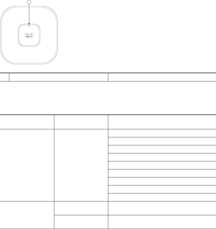
15
Figure 4 Access Point LED Location
The access point status LED indicates various conditions and are described in Table 1.
1Status LED
Table 1 LED Status Indications
Message
Type
Status
LED
Message
Meaning
Boot loader status
sequence
Blinking green DRAM memory test in progress
DRAM memory test OK
Board initialization in progress
Initializing FLASH file system
FLASH memory test OK
Initializing Ethernet
Ethernet OK
Starting Cisco IOS
Initialization successful
Association status Green Normal operating condition, but no wireless
client associated
Blue Normal operating condition, at least one wireless
client association
272378
1
ap3602pgetstart.fm Page 15 Friday, September 21, 2012 10:28 AM

16
Troubleshooting the Access Point Join Process
Access points can fail to join a controller for many reasons: a RADIUS authorization is pending;
self-signed certificates are not enabled on the controller; the access point’s and controller’s regulatory
domains don’t match, and so on.
Operating status Blinking blue Software upgrade in progress
Cycling through green,
red, and off
Discovery/join process in progress
Rapidly cycling
through blue, green,
and red
Access point location command invoked
Blinking red Ethernet link not operational
Boot loader warnings Blinking blue Configuration recovery in progress (MODE
button pushed for 2 to 3 seconds)
Red Ethernet failure or image recovery (MODE
button pushed for 20 to 30 seconds)
Blinking green Image recovery in progress (MODE button
released)
Boot loader errors Red DRAM memory test failure
Blinking red and blue FLASH file system failure
Blinking red and off Environment variable failure
Bad MAC address
Ethernet failure during image recovery
Boot environment failure
No Cisco image file
Boot failure
Cisco IOS errors Red Software failure; try disconnecting and
reconnecting unit power
Cycling through blue,
green, red, and off
General warning; insufficient inline power
Table 1 LED Status Indications (continued)
Message
Type
Status
LED
Message
Meaning
ap3602pgetstart.fm Page 16 Friday, September 21, 2012 10:28 AM

17
Controller software enables you to configure the access points to send all CAPWAP-related errors to
a syslog server. You do not need to enable any debug commands on the controller because all of the
CAPWAP error messages can be viewed from the syslog server itself.
The state of the access point is not maintained on the controller until it receives a CAPWAP join
request from the access point. Therefore, it can be difficult to determine why the CAPWAP discovery
request from a certain access point was rejected. In order to troubleshoot such joining problems
without enabling CAPWAP debug commands on the controller, the controller collects information for
all access points that send a discovery message to it and maintains information for any access points
that have successfully joined it.
The controller collects all join-related information for each access point that sends a CAPWAP
discovery request to the controller. Collection begins with the first discovery message received from
the access point and ends with the last configuration payload sent from the controller to the access
point.
You can view join-related information for up to three times the maximum number of access points
supported by the platform for the 2500 series controllers and the Controller Network Module within
the Cisco 28/37/38xx Series Integrated Services Routers.
Note The maximum number of access points varies for the Cisco WiSM2, depending on which
controller software release is being used.
When the controller is maintaining join-related information for the maximum number of access points,
it does not collect information for any more access points.
An access point sends all syslog messages to IP address 255.255.255.255 by default when any of the
following conditions are met:
•An access point running software release 5.2 or later has been newly deployed.
•An existing access point running software release 5.2 or later has been reset after clearing the
configuration.
If any of these conditions are met and the access point has not yet joined a controller, you can also
configure a DHCP server to return a syslog server IP address to the access point using option 7 on the
server. The access point then starts sending all syslog messages to this IP address.
When the access point joins a controller for the first time, the controller sends the global syslog server
IP address (the default is 255.255.255.255) to the access point. After that, the access point sends all
syslog messages to this IP address until it is overridden by one of the following scenarios:
•The access point is still connected to the same controller, and the global syslog server IP address
configuration on the controller has been changed using the config ap syslog host global
syslog_server_IP_address command. In this case, the controller sends the new global syslog server
IP address to the access point.
ap3602pgetstart.fm Page 17 Friday, September 21, 2012 10:28 AM

18
•The access point is still connected to the same controller, and a specific syslog server IP address
has been configured for the access point on the controller using the config ap syslog host specific
Cisco_AP syslog_server_IP_address command. In this case, the controller sends the new specific
syslog server IP address to the access point.
•The access point is disconnected from the controller and joins another controller. In this case, the
new controller sends its global syslog server IP address to the access point.
•Whenever a new syslog server IP address overrides the existing syslog server IP address, the old
address is erased from persistent storage, and the new address is stored in its place. The access
point also starts sending all syslog messages to the new IP address provided the access point can
reach the syslog server IP address.
You can configure the syslog server for access points and view the access point join information only
from the controller CLI.
A detailed explanation of the join process is on Cisco.com at the following URL:
http://www.Cisco.com/en/US/products/ps6366/products_tech_note09186a00808f8599.shtml
10 Declarations of Conformity and Regulatory Information
This section provides declarations of conformity and regulatory information for the Cisco Aironet
3602P Access Point. You can find additional information at this URL:
www.cisco.com/go/aironet/compliance
Manufacturers Federal Communication Commission Declaration of
Conformity Statement
Models Certification Numbers
AIR-CAP3602P-A-K9 LDK102075P
Tested To Comply
With FCC Standards
FOR HOME OR OFFICE USE
ap3602pgetstart.fm Page 18 Friday, September 21, 2012 10:28 AM

19
Manufacturer:
Cisco Systems, Inc.
170 West Tasman Drive
San Jose, CA 95134-1706
USA
This device complies with Part 15 rules. Operation is subject to the following two conditions:
1. This device may not cause harmful interference, and
2. This device must accept any interference received, including interference that may cause undesired
operation.
Note Review the FCC guidelines for installing and operating outdoor wireless LAN devices at this
URL:
http://www.cisco.com/en/US/prod/collateral/routers/ps272/data_sheet_c78-647116_ps11451
_Products_Data_Sheet.html
LDK102075P is restricted to indoor operation in the 5150-5250Mhz band per FCC guidance.
This equipment has been tested and found to comply with the limits of a Class B digital device,
pursuant to Part 15 of the FCC Rules. These limits are designed to provide reasonable protection
against harmful interference when the equipment is operated in a residential environment. This
equipment generates, uses, and radiates radio frequency energy, and if not installed and used in
accordance with the instructions, may cause harmful interference. However, there is no guarantee that
interference will not occur. If this equipment does cause interference to radio or television reception,
which can be determined by turning the equipment off and on, the user is encouraged to correct the
interference by one of the following measures:
•Reorient or relocate the receiving antenna.
•Increase separation between the equipment and receiver.
•Connect the equipment to an outlet on a circuit different from which the receiver is connected.
•Consult the dealer or an experienced radio/TV technician.
Caution The Part 15 radio device operates on a non-interference basis with other devices operating
at this frequency when using the integrated antennas. Any changes or modification to the
product not expressly approved by Cisco could void the user’s authority to operate this
device.
ap3602pgetstart.fm Page 19 Friday, September 21, 2012 10:28 AM

20
Declaration of Conformity for RF Exposure
This section contains information on compliance with guidelines related to RF exposure.
United States
This system has been evaluated for RF exposure for Humans in reference to ANSI C 95.1 (American
National Standards Institute) limits. The evaluation was based on ANSI C 95.1 and FCC OET Bulletin
65C rev 01.01. The minimum separation distance from the antenna to general bystander is 7.9 inches
(20cm) to maintain compliance.
Declaration of Conformity Statements
All the Declaration of Conformity statements related to this product can be found at the following
location: http://www.ciscofax.com
11 Configuring DHCP Option 43 and DHCP Option 60
This section contains a DHCP Option 43 configuration example on a Windows 2003 Enterprise DHCP
server for use with Cisco Aironet lightweight access points. For other DHCP server implementations,
consult product documentation for configuring DHCP Option 43. In Option 43, you should use the
IP address of the controller management interface.
Note DHCP Option 43 is limited to one access point type per DHCP pool. You must configure a
separate DHCP pool for each access point type.
The 3600 series access point uses the type-length-value (TLV) format for DHCP Option 43. DHCP
servers must be programmed to return the option based on the access point’s DHCP Vendor Class
Identifier (VCI) string (DHCP Option 60). The VCI string for the 3600 series access point is:
Cisco AP c3600
Note If your access point was ordered with the Service Provider Option (AIR-OPT60-DHCP)
selected in the ordering tool, the VCI string for the access point contains ServiceProvider. For
example, a 3600 with this option will return this VCI string:
Cisco AP c3600-ServiceProvider
The format of the TLV block is listed below:
•Type: 0xf1 (decimal 241)
ap3602pgetstart.fm Page 20 Friday, September 21, 2012 10:28 AM

21
•Length: Number of controller IP addresses * 4
•Value: List of WLC management interfaces
To configure DHCP Option 43 in the embedded Cisco IOS DHCP server, follow these steps:
Step 1 Enter configuration mode at the Cisco IOS CLI.
Step 2 Create the DHCP pool, including the necessary parameters such as default router and name
server. A DHCP scope example is as follows:
ip dhcp pool <pool name>
network <IP Network> <Netmask>
default-router <Default router>
dns-server <DNS Server>
Where:
<pool name> is the name of the DHCP pool, such as AP3602
<IP Network> is the network IP address where the controller resides, such as
10.0.15.1
<Netmask> is the subnet mask, such as 255.255.255.0
<Default router> is the IP address of the default router, such as 10.0.0.1
<DNS Server> is the IP address of the DNS server, such as 10.0.10.2
Step 3 Add the option 60 line using the following syntax:
option 60 ascii “
VCI string
”
For the
VCI string
, “Cisco AP c3602”. The quotation marks must be included.
Step 4 Add the option 43 line using the following syntax:
option 43 hex <
hex string
>
The hex string is assembled by concatenating the TLV values shown below:
Type + Length + Value
Type is always f1(hex). Length is the number of controller management IP addresses times 4
in hex. Value is the IP address of the controller listed sequentially in hex.
For example, suppose that there are two controllers with management interface IP addresses,
10.126.126.2 and 10.127.127.2. The type is f1(hex). The length is 2 * 4 = 8 = 08 (hex). The IP
addresses translate to 0a7e7e02 and 0a7f7f02. Assembling the string then yields
f1080a7e7e020a7f7f02. The resulting Cisco IOS command added to the DHCP scope is option 43 hex
f1080a7e7e020a7f7f02.
ap3602pgetstart.fm Page 21 Friday, September 21, 2012 10:28 AM

22
12 Access Point Specifications
Table 2 lists the technical specifications for 3602P access points.
Table 2 Access Point Specifications
Category Specification
Dimensions (LxWxD) 8.68 x 8.68 x 1.84 in. (22.04 x 22.04 x 4.67 cm)
Weight 1.9 lbs (0.86 kg)
Operating temperatures AP3602P: -4 to 131 degrees F (-20 to 55 degrees C)
Storage temperature –22 to 185 degrees F (–30 to 85 degrees C)
Humidity 10% to 90% (noncondensing)
Antennas External
Compliance The 3602P access point complies with UL 2043 for products installed in a
building’s environmental air handling spaces, such as above suspended
ceilings.
Safety UL 60950-1
CAN/CSA C22.2 No. 60950-1
IEC 60950-1 with all national deviations
EN 60950-1
UL 2043
EMI and Susceptibility FCC Part 15.107 and 15.109 Class B
ICES-003 Class B (Canada)
EN 301.489
EN 55022 Class B
EN 55024
VCCI Class B
Radio FCC Part 15.247, 15.407
Canada RSS-210
Japan Telec 33, 66, T71
EN 330.328, EN 301.893
FCC Bulletin OET-65C
Industry Canada RSS-102
Maximum power and
channel settings
Maximum power and the channels allowed in your regulatory domain,
refer to Channels and Maximum Power Settings for Cisco Aironet
Lightweight Access Points. This document is available on Cisco.com.
ap3602pgetstart.fm Page 22 Friday, September 21, 2012 10:28 AM
23
ap3602pgetstart.fm Page 23 Friday, September 21, 2012 10:28 AM

Americas Headquarters
Cisco Systems, Inc.
170 West Tasman Drive
San Jose, CA 95134-1706
USA
www.cisco.com
Tel: 408 526-4000
800 553-NETS (6387)
Fax: 408 527-0883
Asia Pacific Headquarters
Cisco Systems (USA) Pte. Ltd.
168 Robinson Road
#28-01 Capital Tower
Singapore 068912
www.cisco.com
Tel: +65 6317 7777
Fax: +65 6317 7799
Europe Headquarters
Cisco Systems International BV
Haarlerbergpark
Haarlerbergweg 13-19
1101 CH Amsterdam
The Netherlands
www-europe.cisco.com
Tel: 31 0 800 020 0791
Fax: 31 0 20 357 1100
Cisco has more than 200 offices worldwide. Addresses, phone numbers, and fax numbers are listed on the
Cisco Website at www.cisco.com/go/offices.
Cisco and the Cisco Logo are trademarks of Cisco Systems, Inc. and/or its affiliates in the U.S. and other countries. A listing of Cisco's
trademarks can be found at www.cisco.com/go/trademarks. Third party trademarks mentioned are the property of their respective
owners. The use of the word partner does not imply a partnership relationship between Cisco and any other company. (1005R)
© 2012 Cisco Systems, Inc. All rights reserved.
OL-26455-01
ap3602pgetstart.fm Page 24 Friday, September 21, 2012 10:28 AM