Cisco Systems 102078P 2.4Gz Zigbee modules User Manual ap1552Sgsg
Cisco Systems Inc 2.4Gz Zigbee modules ap1552Sgsg
UserManual.wiki
>
Cisco Systems
>
102078P User Manual
>
Manual 2
Contents
1.
Manual
2.
Manual 2
Manual 2
Navigation menu
Upload a User Manual
Namespaces
Wiki Guide
HTML
PDF
Info
Views
User Manual
Discussion / Help
Navigation
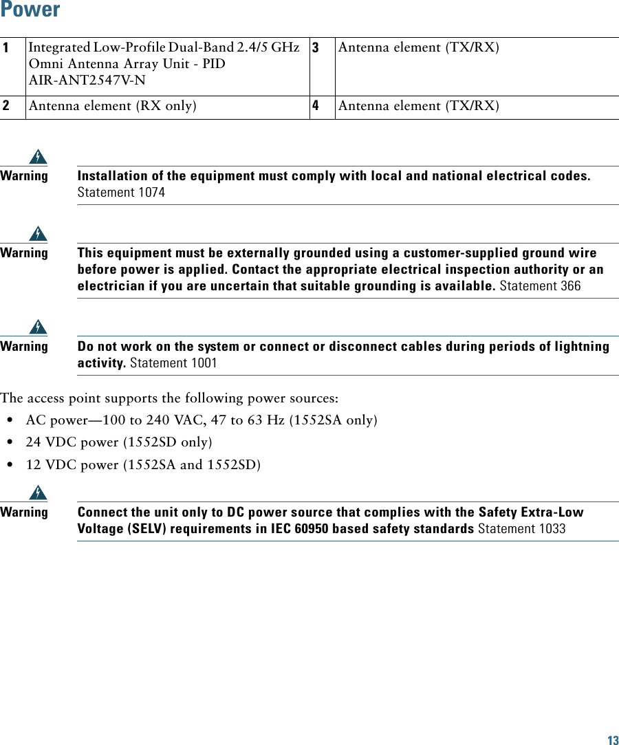
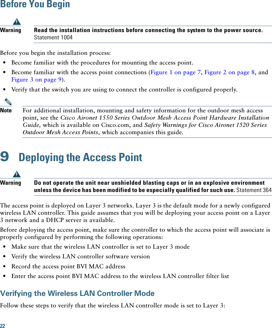
![21To avoid receiver damage and PER degradation, you can use one of the following techniques: • Separate the omnidirectional antennas by at least 2 ft (0.6 m) to avoid receiver damage or by at least 25 ft (7.6 m) to avoid PER degradation. • Reduce the configured transmit power to the minimum level. • Cable the radios together using a combination of attenuators, combiners, or splitters to achieve a total attenuation of at least 60 dB.For a radiated test bed, the following equation describes the relationships among transmit power, antenna gain, attenuation, and receiver sensitivity:txpwr + tx antenna gain + rx ant gain - [attenuation due to antenna spacing] < max rx input levelWhere:txpwr = Radio transmit power leveltx gain = transmitter antenna gainrx gain = receiver antenna gainFor a conducted test bed, the following equation describes the relationships among transmit power, antenna gain, and receiver sensitivity:txpwr - [attenuation due to coaxial RF Attenuator components] < max rx input level (0 dbm)Caution Under no circumstances should you connect the antenna port from one access point to the antenna port of another access point without using an RF attenuator. If you connect antenna ports you must not exceed the maximum survivable receive level of 0 dBm. Never exceed 0 dBm or damage to the access point can occur. Using attenuators, combiners, and splitters having a total of at least 60 dB of attenuation ensures that the receiver is not damaged and PER performance is not degraded.](https://usermanual.wiki/Cisco-Systems/102078P.Manual-2/User-Guide-1599816-Page-21.png)