Cisco Systems 102078P 2.4Gz Zigbee modules User Manual ant24G14
Cisco Systems Inc 2.4Gz Zigbee modules ant24G14
Contents
- 1. Manual
- 2. Manual 2
Manual
Corporate Headquarters:
Copyright © 2004 Cisco Systems, Inc. All rights reserved.
Cisco Systems, Inc., 170 West Tasman Drive, San Jose, CA 95134-1706 USA
Cisco Aironet 14-dBi Vertically Polarized Sector
Antenna (AIR-ANT2414S-R)
This document outlines the specifications, describes the AIR-ANT2414S-R 14-dBi vertically polarized
sector antenna, and provides instructions for mounting and aligning it. The antenna operates in the
2.4-GHz frequency range and is designed for use in bridging environments. The antenna is designed to
be used outdoors and can be mounted on 1.5 in. (3.8 cm) to 2.5 in. (6.3 cm) diameter masts.
The following information is provided in this document.
•Technical Specifications, page 2
•System Requirements, page 3
•Safety Precautions, page 3
•Installation Notes, page 4
•Obtaining Documentation and Submitting a Service Request, page 11
2
Cisco Aironet 14-dBi Vertically Polarized Sector Antenna (AIR-ANT2414S-R)
78-16403-01
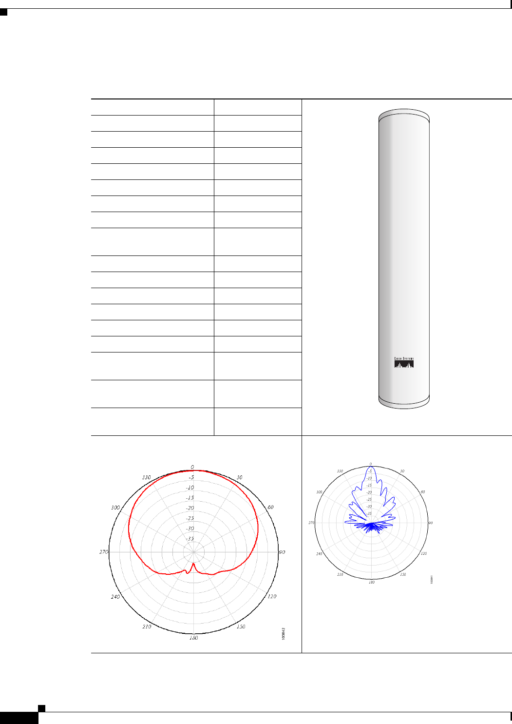
Technical Specifications
Antenna type 90-degree sector
Operating frequency range 2400–2500 MHz
Nominal input impedence 50Ω
2:1 VSWR bandwith 2400–2500 MHz
Gain (including 1.5 m cable) 14 dBi
Polarization Linear, vertical
Azimuth 3-dB beamwidth 90 degrees
Elevation 3-dB beamwidth 8.5 degrees
Cable length and type 5 ft. (1.5 m)
LMR-195 coaxial
Connector type RP-TNC Male
Environment Outdoor
Length 35.9 in. (91.2 cm)
Width 6.4 in. (16.3 cm)
Depth 4.03 in. (10.23 cm)
Weight (with hardware kit) 7.5 lb. (3.4 kg)
Operating temperature range –22°F to 158°F)
(–30°C to 70°C
Storage temperature range –40°F to 185°F
(–40°C to 85°C)
Wind rating 100 mph
(161 kph)
H-Plane Radiation Pattern E-Plane Radiation Pattern
117180
3
Cisco Aironet 14-dBi Vertically Polarized Sector Antenna (AIR-ANT2414S-R)
78-16403-01
System Requirements
This antenna is designed for use with Cisco Aironet access points and bridges but can be used with any
2.4-GHz Cisco Aironet radio device that utilizes an RP-TNC connector.
Note To meet regulatory restrictions, if you are using this antenna with a Cisco Aironet 1300 Series Wireless
Bridge, the antenna must be professionally installed. The network administration or other IT professional
responsible for installing and configuring the unit is a suitable professional installer. Following installation,
access to the unit should be password protected by the network administrator to maintain regulatory
compliance.
Safety Precautions
Warning
This warning symbol means danger. You are in a situation that could cause bodily injury. Before you
work on any equipment, be aware of the hazards involved with electrical circuitry and be familiar
with standard practices for preventing accidents.
Warning
Do not work on the system or connect or disconnect cables during periods of lightning activity.
Warning
This equipment must be grounded. Never defeat the ground conductor or operate the equipment in the
absence of a suitably installed ground conductor. Contact the appropriate electrical inspection
authority or an electrician if you are uncertain that suitable grounding is available.
Warning
Do not locate the antenna near overhead power lines or other electric light or power circuits, or
where it can come into contact with such circuits. When installing the antenna, take extreme care
not to come into contact with such circuits, as they may cause serious injury or death. For proper
installation and grounding of the antenna, please refer to national and local codes (e.g. U.S.:NFPA 70,
National Electrical Code, Article 810, in Canada: Canadian Electrical Code, Section 54).
Each year hundreds of people are killed or injured when attempting to install an antenna. In many of
these cases, the victim was aware of the danger of electrocution, but did not take adequate steps to avoid
the hazard.
For your safety, and to help you achieve a good installation, please read and follow these safety
precautions. They may save your life!
1. If you are installing an antenna for the first time, for your own safety as well as others, seek
professional assistance. Your Cisco sales representative can explain which mounting method to use
for the size and type antenna you are about to install.
2. Select your installation site with safety, as well as performance in mind. Remember: electric power
lines and phone lines look alike. For your safety, assume that any overhead line can kill you.
3. Call your electric power company. Tell them your plans and ask them to come look at your proposed
installation. This is a small inconvenience considering your life is at stake.
4
Cisco Aironet 14-dBi Vertically Polarized Sector Antenna (AIR-ANT2414S-R)
78-16403-01
4. Plan your installation carefully and completely before you begin. Successful raising of a mast or
tower is largely a matter of coordination. Each person should be assigned to a specific task, and
should know what to do and when to do it. One person should be in charge of the operation to issue
instructions and watch for signs of trouble.
5. When installing your antenna, remember:
a. Do not use a metal ladder.
b. Do not work on a wet or windy day.
c. Do dress properly—shoes with rubber soles and heels, rubber gloves, long sleeved shirt or
jacket.
6. If the assembly starts to drop, get away from it and let it fall. Remember, the antenna, mast, cable,
and metal guy wires are all excellent conductors of electrical current. Even the slightest touch of any
of these parts to a power line complete an electrical path through the antenna and the installer: you!
7. If any part of the antenna system should come in contact with a power line, don’t touch it or try to
remove it yourself. Call your local power company. They will remove it safely.
8. If an accident should occur with the power lines call for qualified emergency help immediately.
Installation Notes
The antenna is designed to be mounted on a mast but can be mounted on most flat vertical surfaces. If
you mount the antenna on a vertical surface using the mounting hardware provided, you can adjust the
antenna’s elevation but not its azimuth. Therefore, the surface on which you mount the antenna must be
oriented in the direction of the bridge link.
Choosing a Mounting Location
The antenna is designed to create a directional broadcast pattern. To achieve this pattern, mount the
antenna clear of any obstructions to the sides of the radiating element. If the mounting location is on the
side of a building or tower, the antenna pattern is degraded on the building or tower side.
Site Selection
Before attempting to install your antenna, determine where you can best place the antenna for safety and
performance.
Follow these steps to determine a safe distance from wires, power lines, and trees.
Step 1 Measure the height of your antenna.
Step 2 Add this length to the length of your tower or mast and then double this total for the minimum
recommended safe distance.
Caution If you are unable to maintain this safe distance, stop and get professional help.
5
Cisco Aironet 14-dBi Vertically Polarized Sector Antenna (AIR-ANT2414S-R)
78-16403-01
Generally, the higher an antenna is above the ground, the better it performs. Good practice is to install
your antenna about 5 to 10 ft (1.5 to 3 m) above the roof line and away from all power lines and
obstructions. If possible, find a mounting place directly above your wireless device so that the lead-in
cable can be as short as possible.
Hardware, Tools, and Fasteners Required
A mast mounting installation kit is shipped with the antenna and consists of the following hardware.
•Upper mounting bracket (adjustable)
•Lower mounting bracket (fixed)
•Mast mount clamps
•Four 4.0-in. (10.1 cm) ¼-20 hex head bolts with flat washers, split lock washers, and hex nuts
•Four ¾-in. (1.9 cm) ¼-20 hex head bolts with flat washers, split lock washers, and hex nuts
•Four ¼-20 hex nuts with split lock washers
You will need two 7/16-in. deep well sockets or wrenches to install the antenna. Figure 1 shows the
mounting bracket assembly.
Installation Process
The following sections contains typical procedures for installing the antenna on a mast. Your installation
may vary. The process consists of the following procedures.
•Assembling the mounting brackets
•Attaching the mounting brackets to the antenna
•Mounting the antenna
•Aligning the antenna
•Grounding the antenna
Before you begin, refer to Figure 1 and Figure 2 to become familiar with the installation.
Assembling the Mounting Brackets
Two mounting brackets are provided; one is adjustable and the other is not. Figure 1 shows the adjustable
bracket. The assembly process is the same for both brackets. Follow these steps to assemble the
mounting brackets.
Step 1 Position the mast mount clamp plate inside the antenna bracket.
Step 2 Insert two ¼-20x ¾-in. hex head bolts into the holes in the mast mount clamp plate facing outward as
shown in Figure 1.
Step 3 Place a flat washer and split lock washer on each hex head bolt.
Step 4 Start a ¼-20 hex nut on each hex head bolt and tighten hand tight.
Step 5 Place a flat washer on two 4-inch ¼-20 hex head bolts.
Step 6 Insert the bolts into the holes facing outward in the mast mount clamp plate.
6
Cisco Aironet 14-dBi Vertically Polarized Sector Antenna (AIR-ANT2414S-R)
78-16403-01
Step 7 Install two mast mount clamps on the 4-inch ¼-20 hex head bolts as shown in Figure 1.
Step 8 Install a ¼-20 split lock washer and hex head nut on each bolt and tighten hand tight.
Step 9 Go to Step 1 and assemble the second mounting bracket.
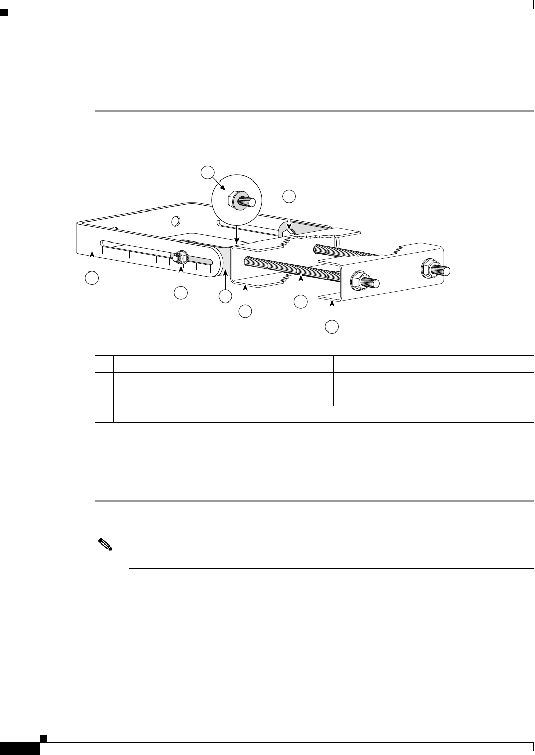
Figure 1 Mounting Bracket Assembly
Attaching the Mounting Brackets to the Antenna
The antenna has studs onto which you attach the installed mounting brackets to it. The adjustable bracket
is installed on the top set of studs. Follow these steps to attach the mounting brackets to the antenna.
Step 1 Position the antenna so that the arrow on the orientation label is pointed up. The arrow points to the top
of the antenna so that it can be installed correctly.
Note The orientation label is located on the back panel of the antenna.
Step 2 Attach the adjustable mounting bracket to the top set of mounting studs.
Step 3 Install two split lock washers and hex nuts on the studs. Use a 7/16-in. socket or wrench to tighten the
nuts. Do not overtighten.
Step 4 Attach the non-adjustable mounting bracket on the bottom set of mounting studs.
Step 5 Install two split lock washers and hex nuts on the studs and tighten as described in Step 3.
1Antenna bracket (adjustable bracket shown) 5Hex head bolt
2¼-20 x ¾-in (1.9 cm) hex head nut 6¼-20 x ¾-in (1.9 cm) hex head bolt
3Mast mount clamp plate 7¼-20 x 4-in hex head bolt details
4Mast mount clamp
117177
012345678
6
1
2
5
4
4
3
7
7
Cisco Aironet 14-dBi Vertically Polarized Sector Antenna (AIR-ANT2414S-R)
78-16403-01
Step 6 Use an appropriate socket or wrench to tighten the mounting bracket fasteners except the mast mount
clamp fasteners.
a. Use a 7/16-in socket or wrench to capture the hex head bolt while you tighten the nuts.
b. Do not complete tighten the nuts. Tighten them just enough so the bracket remains positioned but
can be moved if necessary.
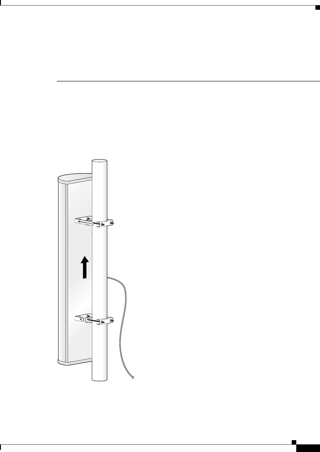
Mounting the Antenna
Figure 2 shows side and rear view of a typical mast installation. Note that the adjustable bracket is in the
top position. Depending on how your mast is configured, you may need to remove one of the mast mount
clamps in order to mount the antenna.
Figure 2 Antenna Mounting Details
117179
8
Cisco Aironet 14-dBi Vertically Polarized Sector Antenna (AIR-ANT2414S-R)
78-16403-01
Follow these steps to mount the antenna on the mast. Make sure you follow all safety precautions that
are appropriate for your installation.
Step 1 Position the antenna on the mast so that the inside mast mount clamps are making good contact with the
mast.
Step 2 If you removed the outside mast mount clamp on the top bracket, reinstall it now. Make sure you have
retained the ¼-20 flat washers and split lock washers on the hex head bolts and start a ¼-20 hex nut on
each bolt.
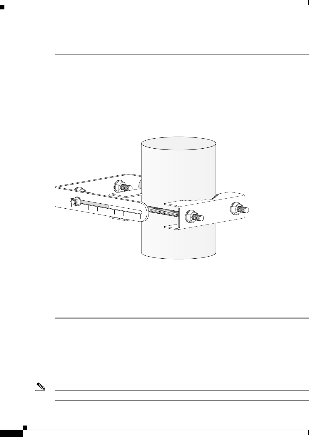
Step 3 Use a 7/16-in. deep well socket or wrench to tighten the nuts. Tighten the nuts enough so that the antenna
will not slip down the mast. See Figure 3.
Figure 3 Mast Mount Clamp Detail
Step 4 If you removed the outside mast mount clamp on the bottom bracket, reinstall it now. Make sure you
have retained the ¼-20 flat washers and split lock washers on the hex head bolts and start a ¼-20 hex nut
on each bolt.
Step 5 Use a 7/16-in. deep well socket or wrench to tighten the nuts. Do not completely tighten the nuts.
Step 6 Rotate the antenna so that it points in the direction of the link you intend to establish.
Aligning the Antenna
The antenna must be properly aligned if it is to be effective and efficient. If you are using this antenna
with the Cisco Aironet 1300 Series Wireless Bridge, a detailed alignment procedure is contained in the
Cisco Aironet 1300 Series Bridge Mounting Instructions, which is available on Cisco.com. The antenna
must also be professionally installed if it is to be used with the 1300 series bridge.
Note Polarization for the antennas you are aligning must be the same.
117178
012345678
9
Cisco Aironet 14-dBi Vertically Polarized Sector Antenna (AIR-ANT2414S-R)
78-16403-01
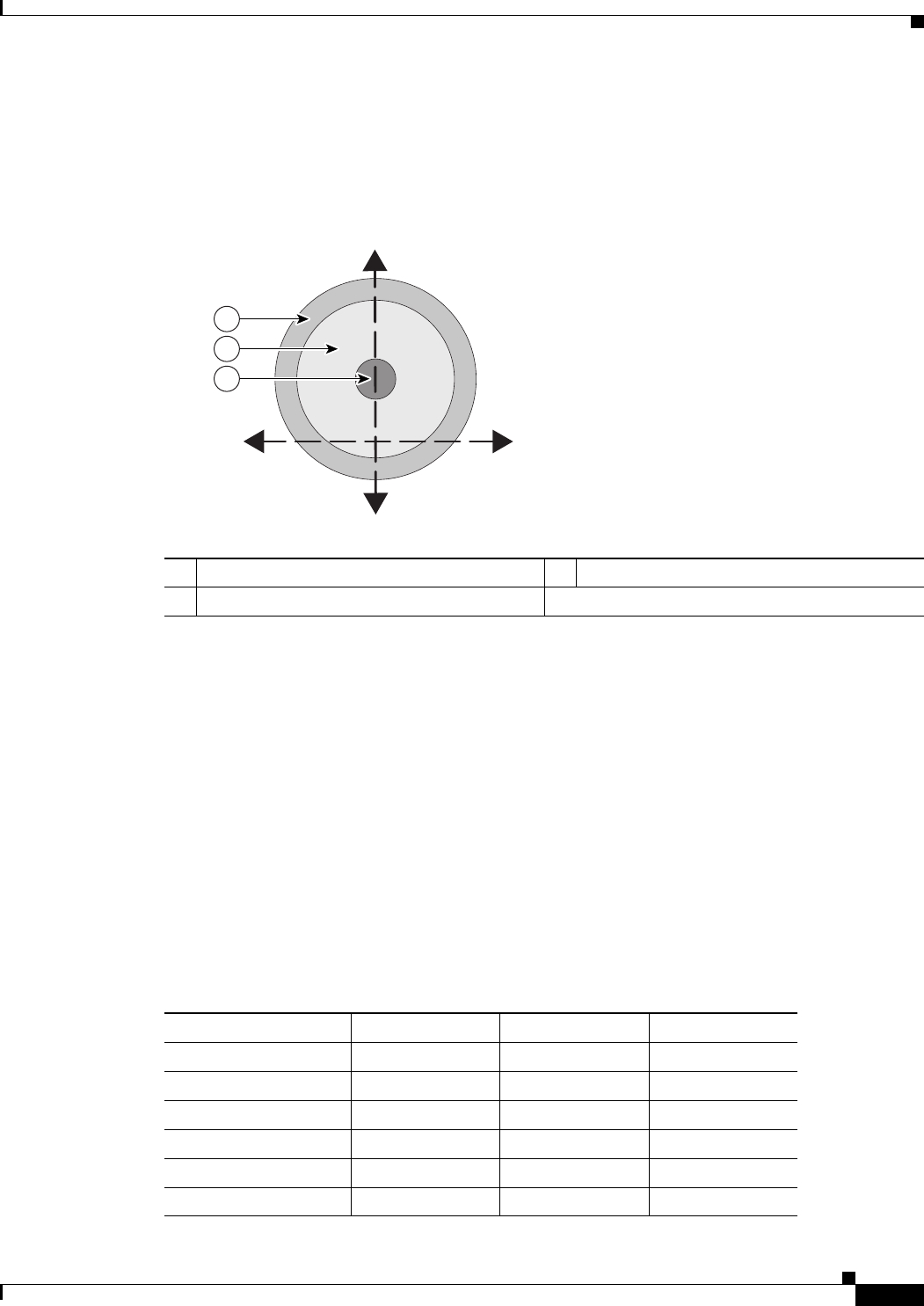
The goal when positioning a directional antenna is to align the local antenna for maximum received
signal strength using the LED indications. The LEDs are convenient and easy to use. Normally, you
observe a single large peak as you pan the antenna across the signal path. Think of the receive signal as
a target (see Figure 4).
Figure 4 Signal Strength Target
The target consists of concentric rings, with the strongest signal at the center and a progressively weaker
signal at the outer rings. As you scan across the signal, you should observe the strong signal level when
the antenna is properly aligned. If a vertical adjustment is required, look for the strong signal level as
you tilt the antenna through its range.
Positioning the Antenna Using LED Indications
You can position the integrated antenna or a directional external antenna using the LEDs only after the
bridge successfully associates with the remote bridge. In installation mode, the Install LED is continuous
amber or green when the bridge has successfully associated. For the first 20 seconds following
association, the bridge reads the received signal strength indication (RSSI) levels from the received
packets and records the maximum value. After 20 seconds, the Ethernet, status, and radio LEDs on the
bridge indicate relative RSSI readings (see Table 1) compared to the maximum recorded during the
initial 20 seconds.
1Weak signal level 3Strong signal level
2Moderate signal level
Horizontal
Vertical
1
2
3
116837
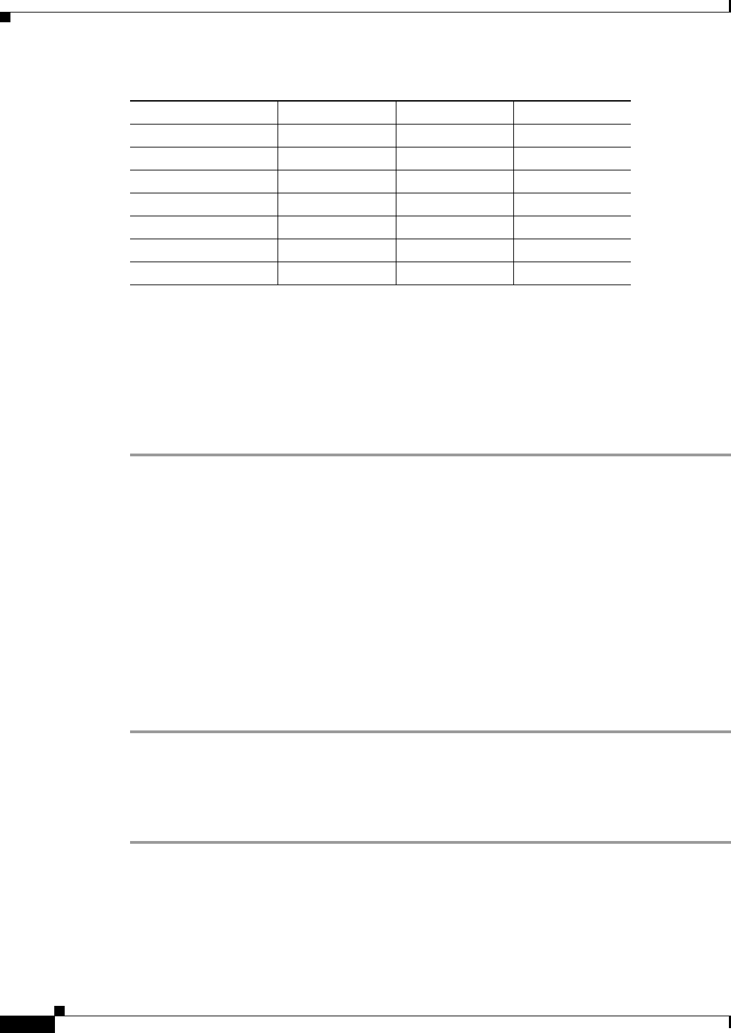
Table 1 Install Mode RSSI Display
Signal Level (dBm) Ethernet LED Status LED Radio LED
–44 or stronger On On On
–47 to –44 Fast blink1On On
–50 to –47 Medium blink2On On
–53 to –50 Slow blink3On On
–54 to –53 Off On On
–57 to –54 Off Fast blink On
10
Cisco Aironet 14-dBi Vertically Polarized Sector Antenna (AIR-ANT2414S-R)
78-16403-01
When you are using LEDs to maximize the signal, adjust the antenna until as many LEDs as possible are
on and the rest are blinking as fast as possible. With all three LEDS on, the signal is good enough to
support the maximum data rate.
To position the antenna using the LED indicators, follow these steps:
Step 1 Verify that the Install LED is either continuous amber or green.
Step 2 Slowly pan the bridge to the left and right of the signal path, and watch for peaks in signal strength. Be
sure to swing the antenna in an arc of 45 degrees to each side to ensure that the passes through the
strongest signal level.
Step 3 Return the bridge to the position where the signal is strongest.
Step 4 Secure the horizontal adjustment by tightening the hex head bolts on the antenna bracket. Tighten the
nuts wrench tight. Do not overtighten.
Step 5 Slowly tilt the antenna, and watch for a peak in signal strength. Use the full vertical adjustment range of
the mounting brackets.
Step 6 Return the bridge to the position where the signal is strongest, normally where all signal strength LEDs
are on. If you are unable to turn on all LEDs, simply maximize the signal.
Step 7 Secure the vertical adjustment by tightening the nuts that secure the adjustable antenna bracket to the
mast mount clamp plate wrench tight. Do not overtighten.
Grounding the Antenna
Follow these steps to ground the antenna in accordance with national electrical code instructions.
Step 1 Use No. 10 AWG copper or No. 8 or larger copper-clad steel or bronze wire as ground wires for both
mast and lead-in. Securely clamp the wire to the bottom of the mast.
Step 2 Secure the lead-in wire to an antenna discharge unit and the mast ground wire to the building with
stand-off insulators spaced from 4 ft (1.2 m) to 8 ft (2.4 m) apart.
Step 3 Mount the antenna discharge unit as close as possible to where the lead-in wire enters the building.
–60 to –57 Off Medium blink On
–63 to –60 Off Slow blink On
–66 to –63 Off Off On
–69 to –66 Off Off Fast blink
–72 to –69 Off Off Medium blink
–75 to –72 Off Off Slow blink
–75 or weaker Off Off Off
1. Blinks once per second.
2. Blinks twice per second.
3. Blinks four times per second.
Table 1 Install Mode RSSI Display (Continued)
Signal Level (dBm) Ethernet LED Status LED Radio LED
11
Cisco Aironet 14-dBi Vertically Polarized Sector Antenna (AIR-ANT2414S-R)
78-16403-01
Step 4 Drill a hole in the building’s wall as close as possible to the equipment to which you will connect the
lead-in cable.
Caution There may be wires in the wall. Make sure your drilling location is clear of any obstructions or other
hazards.
Step 5 Pull the cable through the hole and form a drip loop close to where it enters the building.
Step 6 Thoroughly waterproof the lead-in area.
Step 7 Install a lightning arrestor.
Step 8 Connect the lead-in cable to the equipment.
Suggested Cable
Cisco recommends a high-quality, low-loss cable for use with the antenna.
Note Coaxial cable loses efficiency as the frequency increases, resulting in signal loss. The cable
should be kept as short as possible because cable length also determines the amount of
signal loss (the longer the run, the greater the loss).
The antenna terminates with a RP-TNC plug after a short, 5-ft (1.5-m) cable. The mating connector to
the antenna is an appropriate RP-TNC jack. The connector on the opposite end will vary according to
the type of equipment used.
After the cable is attached to the antenna, make sure that the connections are sealed (if outdoors) to
prevent moisture and other weathering elements from affecting performance. Cisco recommends using
a coax seal (such as CoaxSeal) for outdoor connections. Silicon sealant or electrical tape are not
recommended for sealing outdoor connections.
Obtaining Documentation and Submitting a Service Request
For information on obtaining documentation, submitting a service request, and gathering additional
information, see the monthly What’s New in Cisco Product Documentation, which also lists all new and
revised Cisco technical documentation, at:
http://www.cisco.com/en/US/docs/general/whatsnew/whatsnew.html
Subscribe to the What’s New in Cisco Product Documentation as a Really Simple Syndication (RSS) feed
and set content to be delivered directly to your desktop using a reader application. The RSS feeds are a free
service and Cisco currently supports RSS Version 2.0.
12
Cisco Aironet 14-dBi Vertically Polarized Sector Antenna (AIR-ANT2414S-R)
78-16403-01
Cisco and the Cisco Logo are trademarks of Cisco Systems, Inc. and/or its affiliates in the U.S. and other countries. A listing of Cisco's trademarks
can be found at www.cisco.com/go/trademarks. Third party trademarks mentioned are the property of their respective owners. The use of the word
partner does not imply a partnership relationship between Cisco and any other company. (1005R)