Cisco Systems 102087P Cisco Aironet 802.11ac Dual Band Access Points User Manual Wireless LAN Controller Configuration Guide Part1
Cisco Systems Inc Cisco Aironet 802.11ac Dual Band Access Points Wireless LAN Controller Configuration Guide Part1
Contents
- 1. Manual
- 2. revised manual
- 3. Wireless LAN Controller Configuration Guide_Part1
- 4. Wireless LAN Controller Configuration Guide_Part2
- 5. Wireless LAN Controller Configuration Guide_Part3
- 6. Wireless LAN Controller Configuration Guide_Part4
Wireless LAN Controller Configuration Guide_Part1
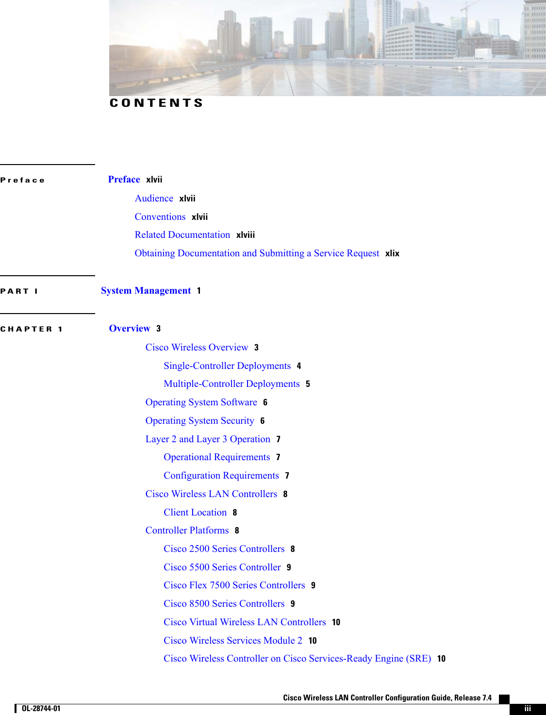


![PrefaceThis preface describes the audience, organization, and conventions of this document. It also providesinformation on how to obtain other documentation. This chapter includes the following sections:•Audience, page xlvii•Conventions, page xlvii•Related Documentation, page xlviii•Obtaining Documentation and Submitting a Service Request, page xlixAudienceThis publication is for experienced network administrators who configure and maintain Cisco wireless LANcontrollers and Cisco lightweight access points.ConventionsThis document uses the following conventions:Table 1: ConventionsIndicationConventionCommands and keywords and user-entered text appear in bold font.bold fontDocument titles, new or emphasized terms, and arguments for which you supplyvalues are in italic font.italic fontElements in square brackets are optional.[ ]Required alternative keywords are grouped in braces and separated by verticalbars.{x | y | z }Optional alternative keywords are grouped in brackets and separated by verticalbars.[x|y|z]Cisco Wireless LAN Controller Configuration Guide, Release 7.4 OL-28744-01 xlvii](https://usermanual.wiki/Cisco-Systems/102087P.Wireless-LAN-Controller-Configuration-Guide-Part1/User-Guide-2323187-Page-47.png)
![IndicationConventionA nonquoted set of characters. Do not use quotation marks around the string orthe string will include the quotation marks.stringTerminal sessions and information the system displays appear in courier font.courier fontNonprinting characters such as passwords are in angle brackets.<>Default responses to system prompts are in square brackets.[]An exclamation point (!) or a pound sign (#) at the beginning of a line of codeindicates a comment line.!, #Means reader take note. Notes contain helpful suggestions or references to material not covered in themanual.NoteMeans the following information will help you solve a problem.TipMeans reader be careful. In this situation, you might perform an action that could result in equipmentdamage or loss of data.CautionRelated DocumentationThese documents provide complete information about Cisco Wireless:•Cisco Wireless LAN Controller configuration guides:http://www.cisco.com/en/US/products/ps10315/products_installation_and_configuration_guides_list.html•Cisco Wireless LAN Controller command references:http://www.cisco.com/en/US/products/ps10315/prod_command_reference_list.html•Cisco Wireless LAN Controller System Message Guide:•http://www.cisco.com/en/US/products/ps10315/products_system_message_guides_list.html•Release Notes for Cisco Wireless LAN Controllers and Lightweight Access Points:•http://www.cisco.com/en/US/products/ps10315/prod_release_notes_list.html•Cisco Wireless Mesh Access Points, Design and Deployment Guide:•http://www.cisco.com/en/US/products/ps11451/products_implementation_design_guides_list.html•Cisco Prime Infrastructure documentation:http://www.cisco.com/en/US/products/ps12239/products_documentation_roadmaps_list.html Cisco Wireless LAN Controller Configuration Guide, Release 7.4xlviii OL-28744-01 PrefaceRelated Documentation](https://usermanual.wiki/Cisco-Systems/102087P.Wireless-LAN-Controller-Configuration-Guide-Part1/User-Guide-2323187-Page-48.png)


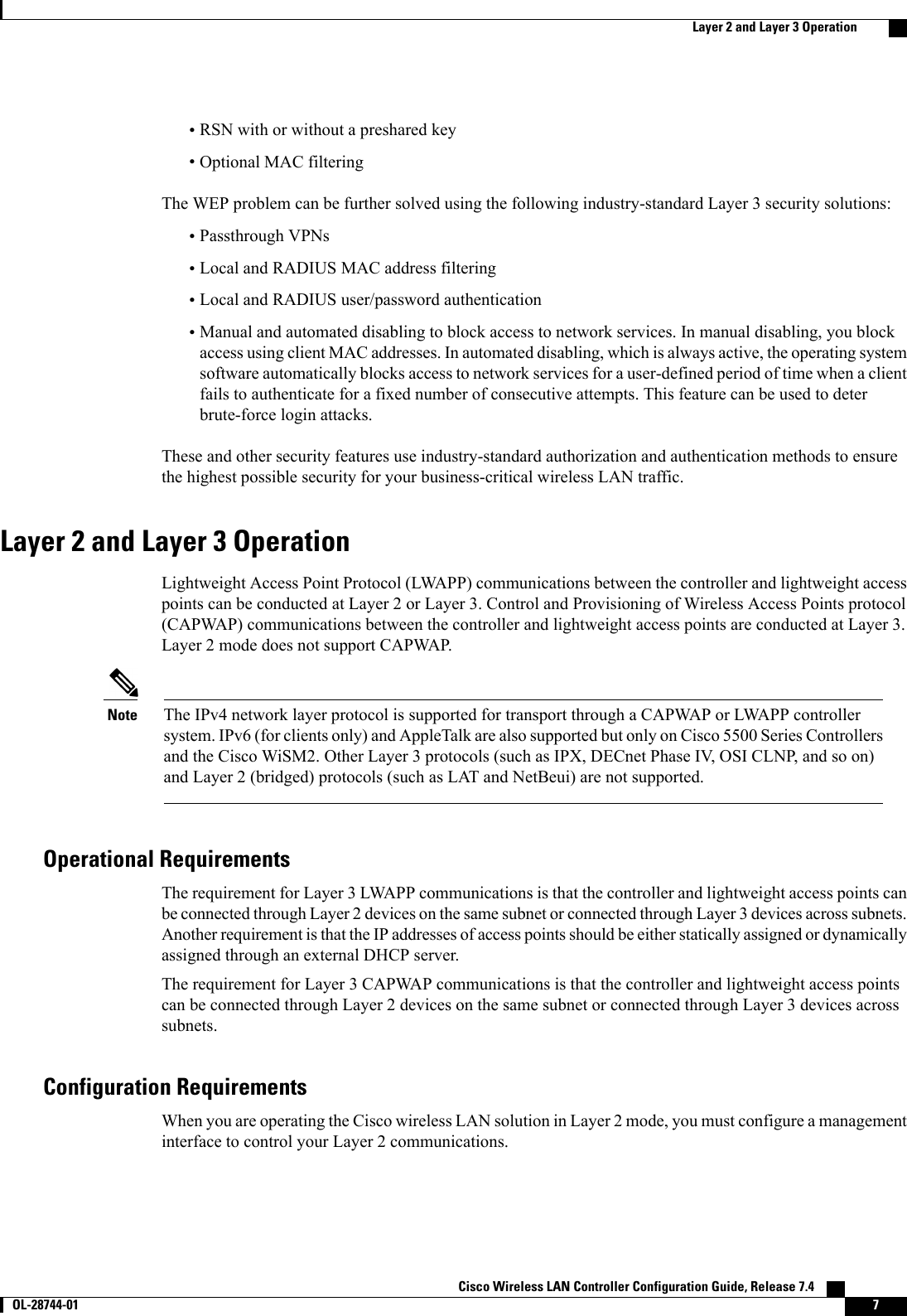


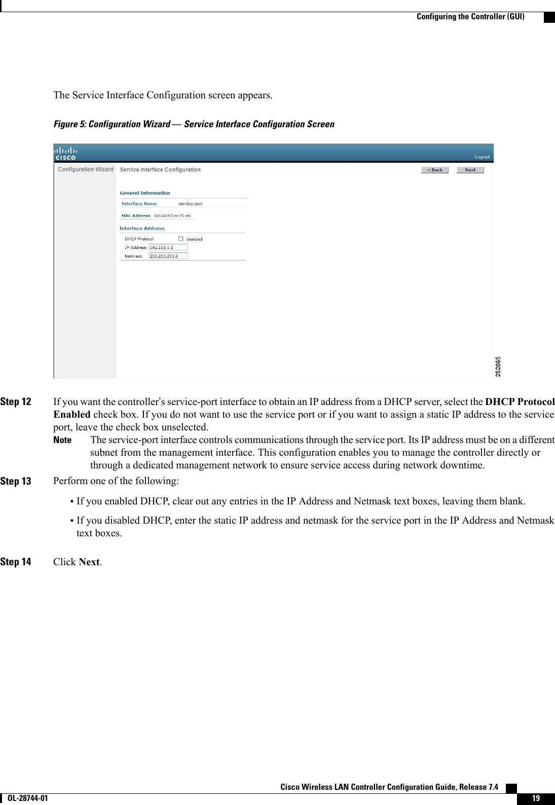
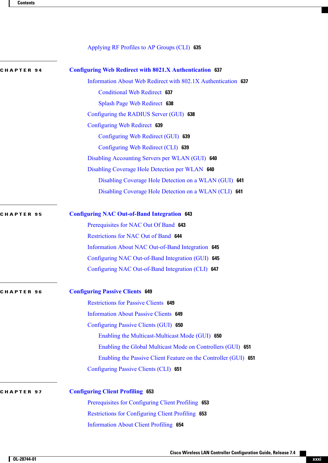
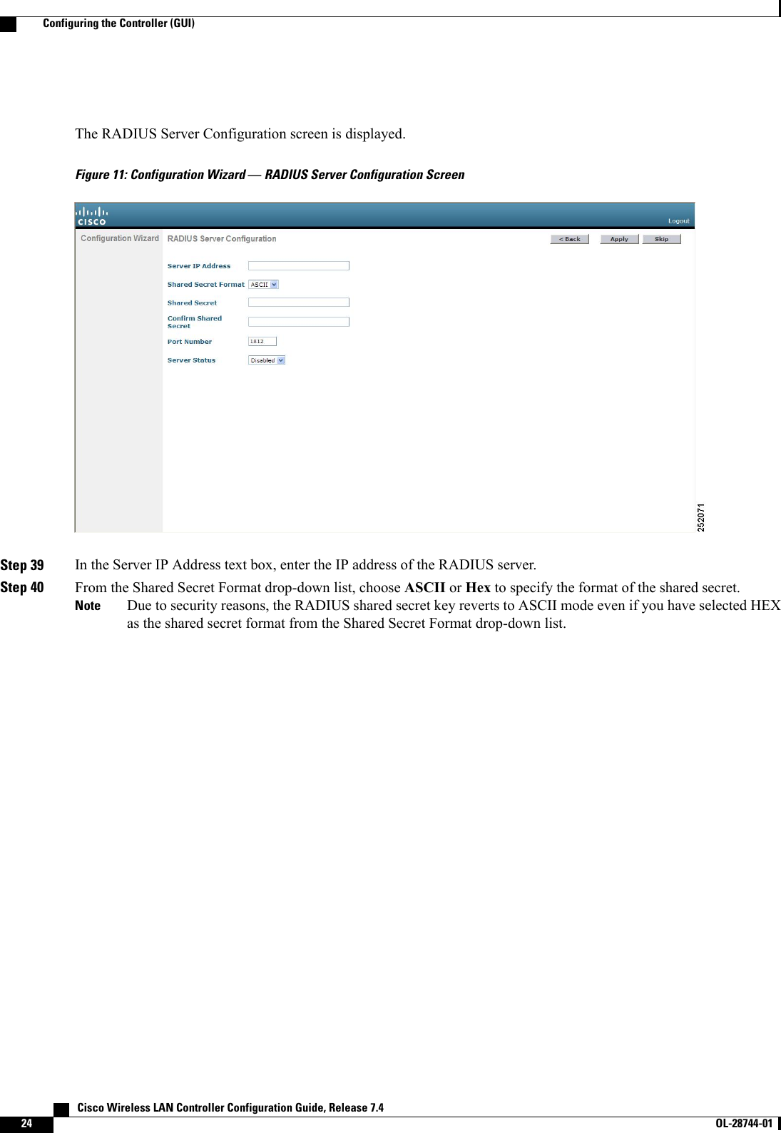
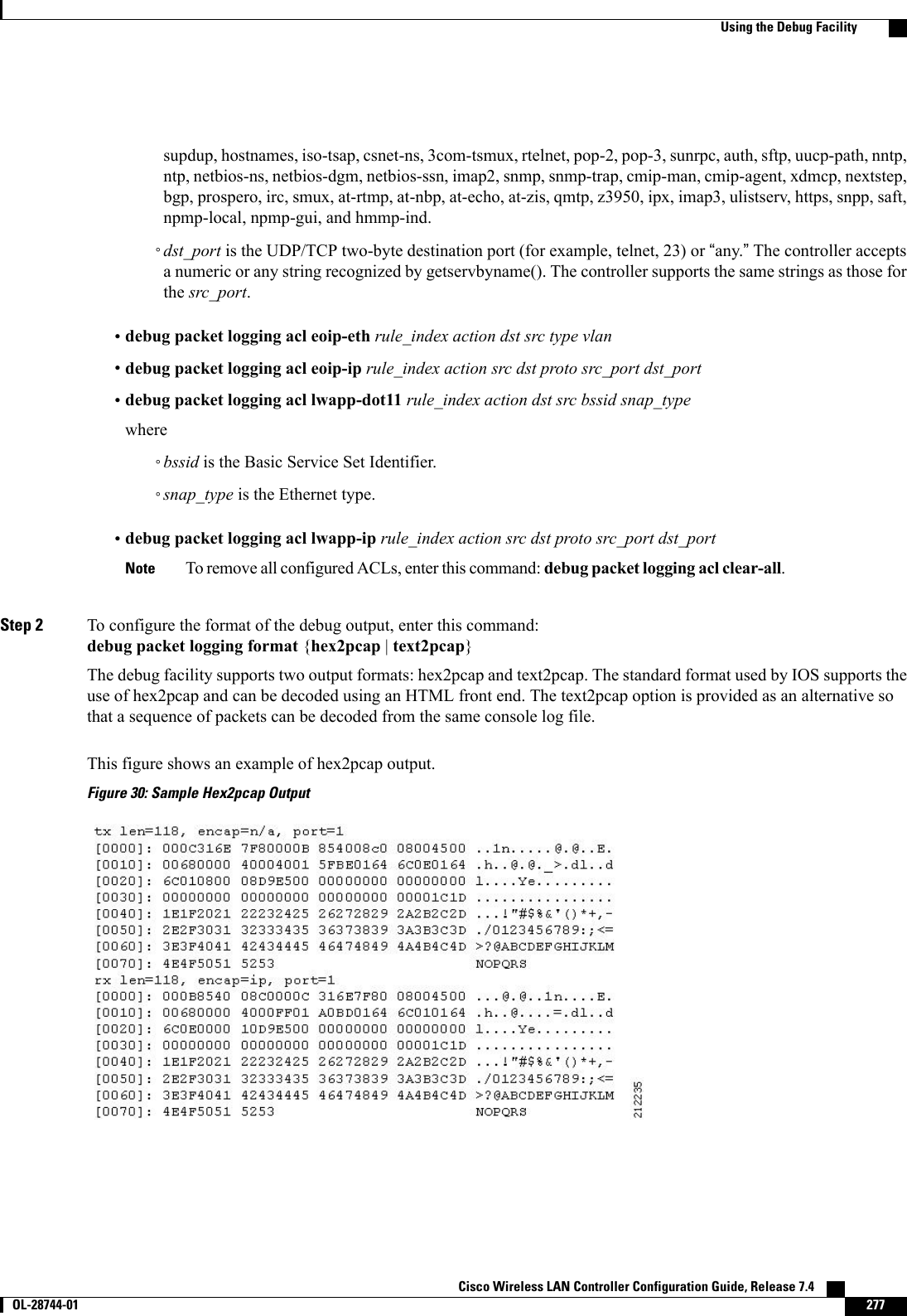
![Step 34 Click Next. The WLAN Configuration screen appears.Figure 10: Configuration Wizard — WLAN Configuration ScreenStep 35 In the Profile Name text box, enter up to 32 alphanumeric characters for the profile name to be assigned to this WLAN.Step 36 In the WLAN SSID text box, enter up to 32 alphanumeric characters for the network name, or service set identifier(SSID). The SSID enables basic functionality of the controller and allows access points that have joined the controllerto enable their radios.Step 37 Click Next.Step 38 When the following message appears, click OK:Default Security applied to WLAN is: [WPA2(AES)][Auth(802.1x)]. You can changethis after the wizard is complete and the system is rebooted.?Cisco Wireless LAN Controller Configuration Guide, Release 7.4 OL-28744-01 23Configuring the Controller (GUI)](https://usermanual.wiki/Cisco-Systems/102087P.Wireless-LAN-Controller-Configuration-Guide-Part1/User-Guide-2323187-Page-73.png)
![When you log into the CLI, you are at the root level. From the root level, you can enter any full commandwithout first navigating to the correct command level.The following table lists commands you use to navigate the CLI and to perform common tasks.Table 2: Commands for CLI Navigation and Common TasksActionCommandAt the root level, view system wide navigationcommandshelpView commands available at the current level?View parameters for a specific commandcommand ?Move down one levelexitReturn from any level to the root levelCtrl-ZAt the root level, save configuration changes fromactive working RAM to nonvolatile RAM (NVRAM)so they are retained after rebootsave configAt the root level, reset the controller without loggingoutreset systemUsing the AutoInstall Feature for Controllers Without a ConfigurationThis section describes how to use the AutoInstall feature for controllers without a configuration.Information About the AutoInstall FeatureWhen you boot up a controller that does not have a configuration, the AutoInstall feature can download aconfiguration file from a TFTP server and then load the configuration onto the controller automatically.If you create a configuration file on a controller that is already on the network (or through a Prime Infrastructurefilter), place that configuration file on a TFTP server, and configure a DHCP server so that a new controllercan get an IP address and TFTP server information, the AutoInstall feature can obtain the configuration filefor the new controller automatically.When the controller boots, the AutoInstall process starts. The controller does not take any action untilAutoInstall is notified that the configuration wizard has started. If the wizard has not started, the controllerhas a valid configuration.If AutoInstall is notified that the configuration wizard has started (which means that the controller does nothave a configuration), AutoInstall waits for an additional 30 seconds. This time period gives you an opportunityto respond to the first prompt from the configuration wizard:Would you like to terminate autoinstall? [yes]:Cisco Wireless LAN Controller Configuration Guide, Release 7.4 OL-28744-01 39Using the AutoInstall Feature for Controllers Without a Configuration](https://usermanual.wiki/Cisco-Systems/102087P.Wireless-LAN-Controller-Configuration-Guide-Part1/User-Guide-2323187-Page-89.png)
![When the 30-second abort timeout expires, AutoInstall starts the DHCP client. You can abort the AutoInstalltask even after this 30-second timeout if you enter Yes at the prompt. However, AutoInstall cannot be abortedif the TFTP task has locked the flash and is in the process of downloading and installing a valid configurationfile.Guidelines and LimitationsAutoInstall uses the following interfaces:•Cisco 5500 Series Controllers◦eth0—Service port (untagged)◦dtl0—Gigabit port 1 through the NPU (untagged)Obtaining an IP Address Through DHCP and Downloading a Configuration File from a TFTPServerAutoInstall attempts to obtain an IP address from the DHCP server until the DHCP process is successful oruntil you abort the AutoInstall process. The first interface to successfully obtain an IP address from the DHCPserver registers with the AutoInstall task. The registration of this interface causes AutoInstall to begin theprocess of obtaining TFTP server information and downloading the configuration file.Following the acquisition of the DHCP IP address for an interface, AutoInstall begins a short sequence ofevents to determine the host name of the controller and the IP address of the TFTP server. Each phase of thissequence gives preference to explicitly configured information over default or implied information and toexplicit host names over explicit IP addresses.The process is as follows:•If at least one Domain Name System (DNS) server IP address is learned through DHCP, AutoInstallcreates a /etc/resolv.conf file. This file includes the domain name and the list of DNS servers that havebeen received. The Domain Name Server option provides the list of DNS servers, and the Domain Nameoption provides the domain name.•If the domain servers are not on the same subnet as the controller, static route entries are installed foreach domain server. These static routes point to the gateway that is learned through the DHCP Routeroption.•The host name of the controller is determined in this order by one of the following:◦If the DHCP Host Name option was received, this information (truncated at the first period [.]) isused as the host name for the controller.◦A reverse DNS lookup is performed on the controller IP address. If DNS returns a hostname, thisname (truncated at the first period [.]) is used as the hostname for the controller.•The IP address of the TFTP server is determined in this order by one of the following:◦If AutoInstall received the DHCP TFTP Server Name option, AutoInstall performs a DNS lookupon this server name. If the DNS lookup is successful, the returned IP address is used as the IPaddress of the TFTP server. Cisco Wireless LAN Controller Configuration Guide, Release 7.440 OL-28744-01 Guidelines and Limitations](https://usermanual.wiki/Cisco-Systems/102087P.Wireless-LAN-Controller-Configuration-Guide-Part1/User-Guide-2323187-Page-90.png)
![AutoInstall does not expect the switch connected to the controller to be configured for either channels.AutoInstall works with a service port in LAG configuration.NoteCisco Prime Infrastructure provides AutoInstall capabilities for controllers. A Cisco Prime Infrastructureadministrator can create a filter that includes the host name, the MAC address, or the serial number of thecontroller and associate a group of templates (a configuration group) to this filter rule. The PrimeInfrastructure pushes the initial configuration to the controller when the controller boots up initially. Afterthe controller is discovered, the Prime Infrastructure pushes the templates that are defined in theconfiguration group. For more information about the AutoInstall feature and Cisco Prime Infrastructure,see the Cisco Prime Infrastructure documentation.NoteExample: AutoInstall OperationThe following is an example of an AutoInstall process from start to finish:Welcome to the Cisco Wizard Configuration ToolUse the '-' character to backupWould you like to terminate autoinstall? [yes]:AUTO-INSTALL: starting now...AUTO-INSTALL: interface 'service-port' - setting DHCP TFTP Filename ==> 'abcd-confg'AUTO-INSTALL: interface 'service-port' - setting DHCP TFTP Server IP ==> 1.100.108.2AUTO-INSTALL: interface 'service-port' - setting DHCP siaddr ==> 1.100.108.2AUTO-INSTALL: interface 'service-port' - setting DHCP Domain Server[0] ==> 1.100.108.2AUTO-INSTALL: interface 'service-port' - setting DHCP Domain Name ==> 'engtest.com'AUTO-INSTALL: interface 'service-port' - setting DHCP yiaddr ==> 172.19.29.253AUTO-INSTALL: interface 'service-port' - setting DHCP Netmask ==> 255.255.255.0AUTO-INSTALL: interface 'service-port' - setting DHCP Gateway ==> 172.19.29.1AUTO-INSTALL: interface 'service-port' registeredAUTO-INSTALL: interation 1 -- interface 'service-port'AUTO-INSTALL: DNS reverse lookup 172.19.29.253 ===> 'wlc-1'AUTO-INSTALL: hostname 'wlc-1'AUTO-INSTALL: TFTP server 1.100.108.2 (from DHCP Option 150)AUTO-INSTALL: attempting download of 'abcd-confg'AUTO-INSTALL: TFTP status - 'TFTP Config transfer starting.' (2)AUTO-INSTALL: interface 'management' - setting DHCP file ==> 'bootfile1'AUTO-INSTALL: interface 'management' - setting DHCP TFTP Filename ==> 'bootfile2-confg'AUTO-INSTALL: interface 'management' - setting DHCP siaddr ==> 1.100.108.2AUTO-INSTALL: interface 'management' - setting DHCP Domain Server[0] ==> 1.100.108.2AUTO-INSTALL: interface 'management' - setting DHCP Domain Server[1] ==> 1.100.108.3AUTO-INSTALL: interface 'management' - setting DHCP Domain Server[2] ==> 1.100.108.4AUTO-INSTALL: interface 'management' - setting DHCP Domain Name ==> 'engtest.com'AUTO-INSTALL: interface 'management' - setting DHCP yiaddr ==> 1.100.108.238AUTO-INSTALL: interface 'management' - setting DHCP Netmask ==> 255.255.254.0AUTO-INSTALL: interface 'management' - setting DHCP Gateway ==> 1.100.108.1AUTO-INSTALL: interface 'management' registeredAUTO-INSTALL: TFTP status - 'Config file transfer failed - Error from server: File notfound' (3)AUTO-INSTALL: attempting download of 'wlc-1-confg'AUTO-INSTALL: TFTP status - 'TFTP Config transfer starting.' (2)AUTO-INSTALL: TFTP status - 'TFTP receive complete... updating configuration.' (2)AUTO-INSTALL: TFTP status - 'TFTP receive complete... storing in flash.' (2)AUTO-INSTALL: TFTP status - 'System being reset.' (2)Resetting system Cisco Wireless LAN Controller Configuration Guide, Release 7.442 OL-28744-01 Guidelines and Limitations](https://usermanual.wiki/Cisco-Systems/102087P.Wireless-LAN-Controller-Configuration-Guide-Part1/User-Guide-2323187-Page-92.png)


![Step 2 Specify the maximum number of sessions for the license agent by entering this command:config license agent max-sessions sessionsThe valid range for the sessions parameter is 1 to 25 (inclusive), and the default value is 9.Step 3 Enable the license agent to receive license requests from the CLM and to specify the URL where the license agent receivesthe requests by entering this command:config license agent listener http {plaintext |encrypt}url authenticate [none] [max-message size] [acl acl]The valid range for the size parameter is 0 to 65535 bytes, and the default value is 0.To prevent the license agent from receiving license requests from the CLM, enter the config license agentlistener http disable command. The default value is disabled.NoteStep 4 Configure the license agent to send license notifications to the CLM and to specify the URL where the license agentsends the notifications by entering this command:config license agent notify url username passwordTo prevent the license agent from sending license notifications to the CLM, enter the config license agent notifydisable username password command. The default value is disabled.NoteStep 5 Enter the save config command to save your changes.Step 6 See statistics for the license agent’s counters or sessions by entering this command:show license agent {counters |sessions}Information similar to the following appears for the show license agent counters command:License Agent CountersRequest Messages Received:10: Messages with Errors:1Request Operations Received:9: Operations with Errors:0Notification Messages Sent:12: Transmission Errors:0: Soap Errors:0Information similar to the following appears for the show license agent sessions command:License Agent Sessions: 1 open, maximum is 9To clear the license agent’s counter or session statistics, enter the clear license agent {counters |sessions}command.NoteCisco Wireless LAN Controller Configuration Guide, Release 7.4 OL-28744-01 73Configuring the License Agent](https://usermanual.wiki/Cisco-Systems/102087P.Wireless-LAN-Controller-Configuration-Guide-Part1/User-Guide-2323187-Page-123.png)


![•The number of broadcast neighbor updates sentStep 3 View the roaming history for a particular client by entering this command:show client roam-history client_macThis command provides the following information:•The time when the report was received•The MAC address of the access point to which the client is currently associated•The MAC address of the access point to which the client was previously associated•The channel of the access point to which the client was previously associated•The SSID of the access point to which the client was previously associated•The time when the client disassociated from the previous access point•The reason for the client roamDebugging CCX Client Roaming Issues (CLI)If you experience any problems with CCX Layer 2 client roaming, enter this command:debug l2roam [detail |error |packet |all] {enable |disable}Cisco Wireless LAN Controller Configuration Guide, Release 7.4 OL-28744-01 119Debugging CCX Client Roaming Issues (CLI)](https://usermanual.wiki/Cisco-Systems/102087P.Wireless-LAN-Controller-Configuration-Guide-Part1/User-Guide-2323187-Page-169.png)


![d) Click Apply.e) Click Save Configuration.Configuring Application Visibility and Control (CLI)•Create or delete an AVC profile by entering this command:config avc profile avc-profile-name {create |delete}•Add a rule for an AVC profile by entering this command:config avc profile avc-profile-name rule add application application-name {drop |mark dscp-value}•Remove a rule for an AVC profile by entering this command:config avc profile avc-profile-name rule remove application application-name•Configure an AVC profile to a WLAN by entering this command:config wlan avc wlan-id profile avc-profile-name {enable |disable}•Configure application visibility for a WLAN by entering this command:config wlan avc wlan-id visibility {enable |disable}Application visibility is the subset of an AVC profile. Therefore, visibility isautomatically enabled when you configure an AVC profile on the WLAN.Note•View information about all AVC profile or a particular AVC profile by entering this command:show avc profile {summary |detailed avc-profile-name}•View information about AVC applications by entering this command:show avc applications [application-group]•View various statistical information about AVC by entering this command:show avc statistics•Configure troubleshooting for AVC events by entering this command:debug avc events {enable |disable}•Configure troubleshooting for AVC errors by entering this command:debug avc error {enable |disable}Cisco Wireless LAN Controller Configuration Guide, Release 7.4 OL-28744-01 133Configuring Application Visibility and Control (CLI)](https://usermanual.wiki/Cisco-Systems/102087P.Wireless-LAN-Controller-Configuration-Guide-Part1/User-Guide-2323187-Page-183.png)

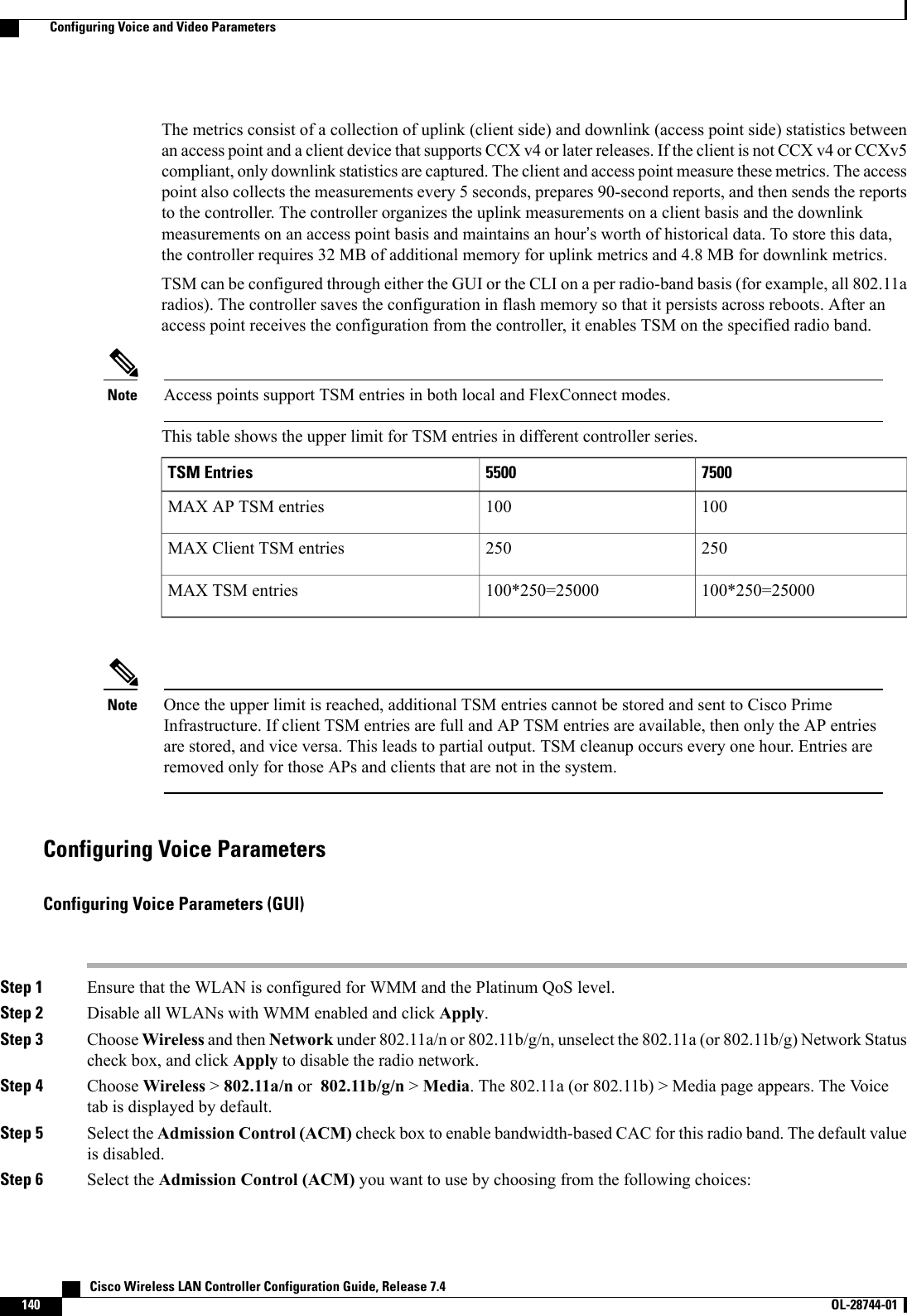
![Table 4: TSPEC Request Handling ExamplesTSPEC with ExpeditedBandwidth RequestNormalTSPECRequestUsage2Reservedbandwidthfor voicecalls1CAC ModeAdmittedAdmittedLess than 75%75%(defaultsetting)Bandwidth-basedCACAdmittedRejectedBetween 75% and 90%(reserved bandwidth forvoice calls exhausted)RejectedRejectedMore than 90%AdmittedAdmittedLess than 75%Load-based CACAdmittedRejectedBetween 75% and 85%(reserved bandwidth forvoice calls exhausted)RejectedRejectedMore than 85%1For bandwidth-based CAC, the voice call bandwidth usage is per access point and does not take into account co-channel access points. For load-based CAC,the voice call bandwidth usage is measured for the entire channel.2Bandwidth-based CAC (consumed voice and video bandwidth) or load-based CAC (channel utilization [Pb]).Admission control for TSPEC g711-40ms codec type is supported.NoteWhen video ACM is enabled, the controller rejects a video TSPEC if the non-MSDU size in the TSPECis greater than 149 or the mean data rate is greater than 1 Kbps.NoteU-APSDUnscheduled automatic power save delivery (U-APSD) is a QoS facility defined in IEEE 802.11e that extendsthe battery life of mobile clients. In addition to extending battery life, this feature reduces the latency of trafficflow delivered over the wireless media. Because U-APSD does not require the client to poll each individualpacket buffered at the access point, it allows delivery of multiple downlink packets by sending a single uplinktrigger packet. U-APSD is enabled automatically when WMM is enabled.Traffic Stream MetricsIn a voice-over-wireless LAN (VoWLAN) deployment, traffic stream metrics (TSM) can be used to monitorvoice-related metrics on the client-access point air interface. It reports both packet latency and packet loss.You can isolate poor voice quality issues by studying these reports.Cisco Wireless LAN Controller Configuration Guide, Release 7.4 OL-28744-01 139Configuring Voice and Video Parameters](https://usermanual.wiki/Cisco-Systems/102087P.Wireless-LAN-Controller-Configuration-Guide-Part1/User-Guide-2323187-Page-189.png)
![Step 9 Configure the codec name and sample interval as parameters and to calculate the required bandwidth per call by enteringthis command:config {802.11a |802.11b}cac voice sip codec {g711 |g729}sample-interval number_msecsStep 10 Configure the bandwidth that is required per call by entering this command:config {802.11a |802.11b}cac voice sip bandwidth bandwidth_kbps sample-interval number_msecsStep 11 Reenable all WLANs with WMM enabled by entering this command:config wlan enable wlan_idStep 12 Reenable the radio network by entering this command:config {802.11a |802.11b}enable networkStep 13 View the TSM voice metrics by entering this command:show [802.11a | 802.11b] cu-metrics AP_NameThe command also displays the channel utilization metrics.Step 14 Enter the save config command to save your settings.Step 15 Configure voice automatically for a WLAN by entering this command:config auto-configure voice cisco wlan-id radio {802.11a |802.11b |all}Step 16 Enter the save config command to save your settings.Configuring Video ParametersConfiguring Video Parameters (GUI)Step 1 Ensure that the WLAN is configured for WMM and the Gold QoS level.Step 2 Disable all WLANs with WMM enabled and click Apply.Step 3 Choose Wireless and then Network under 802.11a/n or 802.11b/g/n, unselect the 802.11a (or 802.11b/g)NetworkStatus check box, and click Apply to disable the radio network.Step 4 Choose Wireless >802.11a/n or 802.11b/g/n >Media. The 802.11a (or 802.11b) > Media page appears.Step 5 In the Video tab, select the Admission Control (ACM) check box to enable video CAC for this radio band. The defaultvalue is disabled.Step 6 From the CAC Method drop-down list, choose between Static and Load Based methods.The static CAC method is based on the radio and the load-based CAC method is based on the channel.For TSpec and SIP based CAC for video calls, only Static method is supported.NoteStep 7 In the Max RF Bandwidth text box, enter the percentage of the maximum bandwidth allocated to clients for videoapplications on this radio band. When the client reaches the value specified, the access point rejects new requests on thisradio band.The range is 5% to 85%. The sum of maximum bandwidth percentage of voice and video should not exceed 85%. Thedefault is 0%.Cisco Wireless LAN Controller Configuration Guide, Release 7.4 OL-28744-01 143Configuring Voice and Video Parameters](https://usermanual.wiki/Cisco-Systems/102087P.Wireless-LAN-Controller-Configuration-Guide-Part1/User-Guide-2323187-Page-193.png)
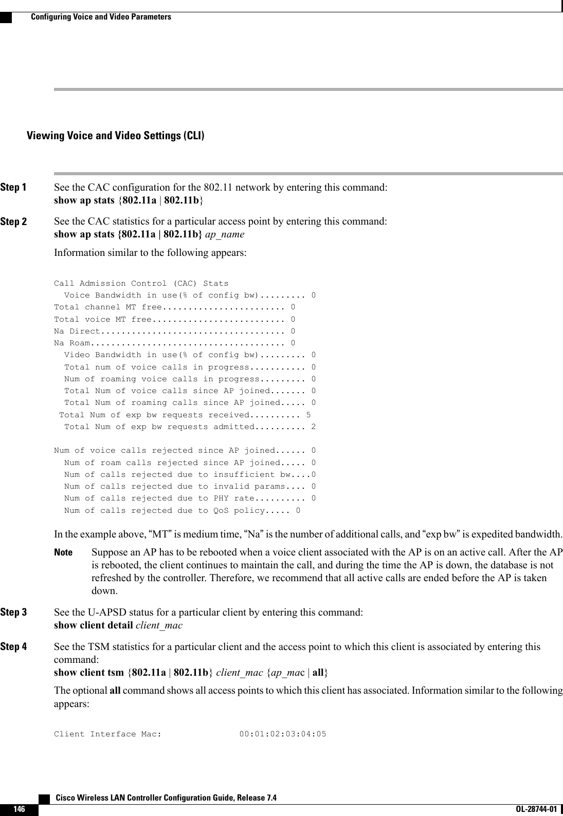
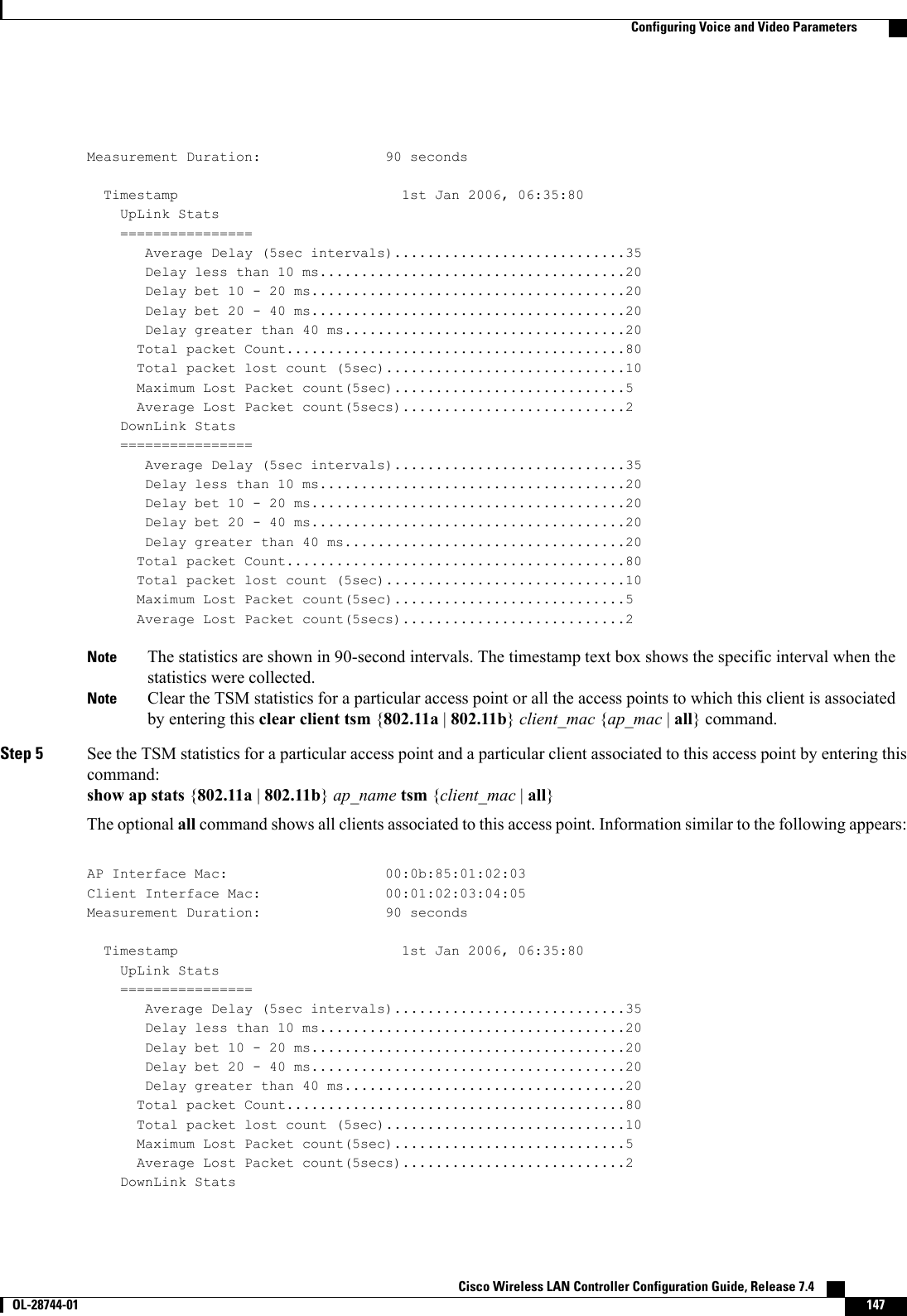
![================Average Delay (5sec intervals)............................35Delay less than 10 ms.....................................20Delay bet 10 - 20 ms......................................20Delay bet 20 - 40 ms......................................20Delay greater than 40 ms..................................20Total packet Count.........................................80Total packet lost count (5sec).............................10Maximum Lost Packet count(5sec)............................5Average Lost Packet count(5secs)...........................2The statistics are shown in 90-second intervals. The timestamp text box shows the specific interval when thestatistics were collected.NoteStep 6 Enable or disable debugging for call admission control (CAC) messages, events, or packets by entering this command:debug cac {all |event |packet}{enable |disable}where all configures debugging for all CAC messages, event configures debugging for all CAC events, and packetconfigures debugging for all CAC packets.Step 7 Use the following command to perform voice diagnostics and to view the debug messages between a maximum of two802.11 clients:debug voice-diag {enable |disable}mac-id mac-id2 [verbose]The verbose mode is an optional argument. When the verbose option is used, all debug messages are displayed in theconsole. You can use this command to monitor a maximum of two 802.11 clients. If one of the clients is a non-WiFiclient, only the 802.11 client is monitored for debug messages.It is implicitly assumed that the clients being monitored are oncall.NoteThe debug command automatically stops after 60minutes.NoteStep 8 Use the following commands to view various voice-related parameters:•show client voice-diag statusDisplays information about whether voice diagnostics is enabled or disabled. If enabled, will also displays informationabout the clients in the watch list and the time remaining for the diagnostics of the voice call.If voice diagnostics is disabled when the following commands are entered, a message indicating that voice diagnosticsis disabled appears.•show client voice-diag tspecDisplays the TSPEC information sent from the clients that are enabled for voice diagnostics.•show client voice-diag qos-mapDisplays information about the QoS/DSCP mapping and packet statistics in each of the four queues: VO, VI, BE,BK. The different DSCP values are also displayed.•show client voice-diag avrg_rssiDisplay the client’s RSSI values in the last 5 seconds when voice diagnostics is enabled.•show client voice-diag roam-historyDisplays information about the last three roaming calls. The output contains the timestamp, access point associatedwith roaming, roaming reason, and if there is a roaming failure, the reason for the roaming-failure. Cisco Wireless LAN Controller Configuration Guide, Release 7.4148 OL-28744-01 Configuring Voice and Video Parameters](https://usermanual.wiki/Cisco-Systems/102087P.Wireless-LAN-Controller-Configuration-Guide-Part1/User-Guide-2323187-Page-198.png)

![Viewing Cisco Discovery Protocol Information (CLI)Step 1 See the status of CDP and to view CDP protocol information by entering this command:show cdpStep 2 See a list of all CDP neighbors on all interfaces by entering this command:show cdp neighbors [detail]The optional detail command provides detailed information for the controller’s CDP neighbors.This command shows only the CDP neighbors of the controller. It does not show the CDP neighbors of thecontroller’s associated access points. Additional commands are provided below to show the list of CDP neighborsper access point.NoteStep 3 See all CDP entries in the database by entering this command:show cdp entry allStep 4 See CDP traffic information on a given port (for example, packets sent and received, CRC errors, and so on) by enteringthis command:show cdp trafficStep 5 See the CDP status for a specific access point by entering this command:show ap cdp ap-name Cisco_APStep 6 See the CDP status for all access points that are connected to the controller by entering this command:show ap cdp allStep 7 See a list of all CDP neighbors for a specific access point by entering these commands:•show ap cdp neighbors ap-name Cisco_AP•show ap cdp neighbors detail Cisco_APThe access point sends CDP neighbor information to the controller only when the information changes.NoteStep 8 See a list of all CDP neighbors for all access points connected to the controller by entering these commands:•show ap cdp neighbors all•show ap cdp neighbors detail allThe access point sends CDP neighbor information to the controller only when the information changes.NoteGetting CDP Debug Information•Get debug information related to CDP packets by entering by entering this command:Cisco Wireless LAN Controller Configuration Guide, Release 7.4 OL-28744-01 163Getting CDP Debug Information](https://usermanual.wiki/Cisco-Systems/102087P.Wireless-LAN-Controller-Configuration-Guide-Part1/User-Guide-2323187-Page-213.png)
![Step 4 For Cisco WiSM2, shut down the controller port channel on the Catalyst switch to allow the controller to reboot beforethe access points start downloading the software.Step 5 Disable any WLANs on the controller using the config wlan disable wlan_id command.Step 6 Specify access points that will receive the predownload image.Use one of these commands to specify access points for predownload:•Specify access points for predownload by entering this command:config ap image predownload {primary |backup} {ap_name |all}The primary image is the new image; the backup image is the existing image. Access points always boot with theprimary image.•Swap an access point’s primary and backup images by entering this command:config ap image swap {ap_name |all}•Display detailed information on access points specified for predownload by entering this command:show ap image {all |ap-name}The output lists access points that are specified for predownloading and provides for each access point, primary andsecondary image versions, the version of the predownload image, the predownload retry time (if necessary), and thenumber of predownload attempts. The output also includes the predownload status for each device. The status of theaccess points is as follows:•None—The access point is not scheduled for predownload.•Predownloading—The access point is predownloading the image.•Not supported—The access point (1120, 1230, and 1310) does not support predownloading.•Initiated—The access point is waiting to get the predownload image because the concurrent download limit hasbeen reached.•Failed—The access point has failed 64 predownload attempts.•Complete—The access point has completed predownloading.Step 7 Set a reboot time for the controller and the access points.Use one of these commands to schedule a reboot of the controller and access points:•Specify the amount of time delay before the devices reboot by entering this command:reset system in HH:MM:SS image {swap |no-swap}reset-aps [save-config]The swap operand in the reset command will result in the swapping of the primary and backup imageson both the controller and the access point.The controller sends a reset message to all joined access points, and then the controller resets.Note•Specify a date and time for the devices to reboot by entering this command:reset system at YYYY-MM-DD HH:MM:SS image {swap |no-swap}reset-aps [save-config]The controller sends a reset message to all joined access points, and then the controller resets.The swap operand in the reset command will result in the swapping of the primary and backup imageson both the controller and the access point.Note Cisco Wireless LAN Controller Configuration Guide, Release 7.4186 OL-28744-01 Upgrading the Controller Software](https://usermanual.wiki/Cisco-Systems/102087P.Wireless-LAN-Controller-Configuration-Guide-Part1/User-Guide-2323187-Page-236.png)

![Some TFTP servers require only a forward slash (/) as the TFTP server IP address, and the TFTP serverautomatically determines the path to the correct directory.Note7Specify the download path by entering this command:transfer download path absolute-tftp-server-path-to-file8Specify the file to be downloaded by entering this command:transfer download filename {filename.jpg |filename.gif |filename.png}9View your updated settings and answer yto the prompt to confirm the current download settings and start the downloadby entering this command:transfer download start10 Save your settings by entering this command:save configIf you ever want to remove this logo from the web authentication login page, enter the clear webimagecommand.NoteStep 10 Follow the instructions in the Verifying the Web Authentication Login Page Settings (CLI), on page 228 section to verifyyour settings.Example: Creating a Customized Web Authentication Login PageThis section provides information on creating a customized web authentication login page, which can thenbe accessed from an external web server.Here is a web authentication login page template. It can be used as a model when creating your own customizedpage:<html><head><meta http-equiv="Pragma" content="no-cache"><meta HTTP-EQUIV="Content-Type" CONTENT="text/html; charset=iso-8859-1"><title>Web Authentication</title><script>function submitAction(){var link = document.location.href;var searchString = "redirect=";var equalIndex = link.indexOf(searchString);var redirectUrl = "";if (document.forms[0].action == "") {var url = window.location.href;var args = new Object();var query = location.search.substring(1);var pairs = query.split("&");for(var i=0;i<pairs.length;i++){var pos = pairs[i].indexOf('=');if(pos == -1) continue;var argname = pairs[i].substring(0,pos);var value = pairs[i].substring(pos+1);args[argname] = unescape(value);}document.forms[0].action = args.switch_url;}Cisco Wireless LAN Controller Configuration Guide, Release 7.4 OL-28744-01 221Choosing the Default Web Authentication Login Page](https://usermanual.wiki/Cisco-Systems/102087P.Wireless-LAN-Controller-Configuration-Guide-Part1/User-Guide-2323187-Page-271.png)
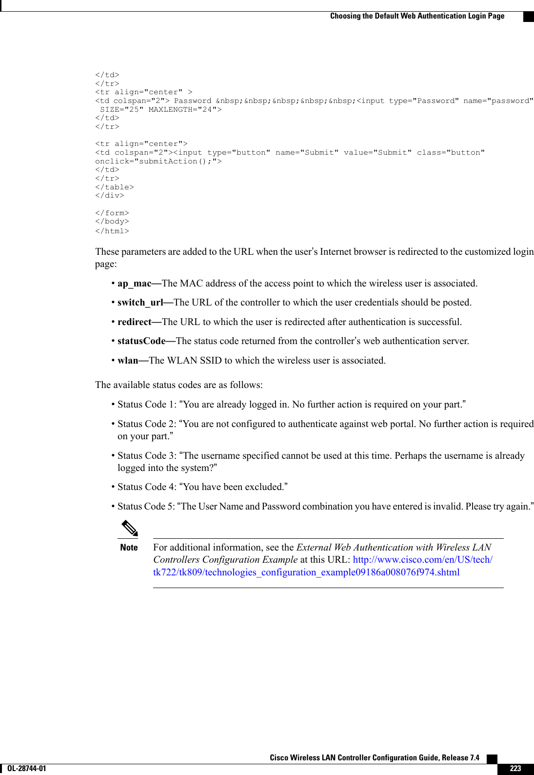
![if(equalIndex >= 0) {equalIndex += searchString.length;redirectUrl = "";redirectUrl += link.substring(equalIndex);}if(redirectUrl.length > 255)redirectUrl = redirectUrl.substring(0,255);document.forms[0].redirect_url.value = redirectUrl;document.forms[0].buttonClicked.value = 4;document.forms[0].submit();}function loadAction(){var url = window.location.href;var args = new Object();var query = location.search.substring(1);var pairs = query.split("&");for(var i=0;i<pairs.length;i++){var pos = pairs[i].indexOf('=');if(pos == -1) continue;var argname = pairs[i].substring(0,pos);var value = pairs[i].substring(pos+1);args[argname] = unescape(value);}//alert( "AP MAC Address is " + args.ap_mac);//alert( "The Switch URL to post user credentials is " + args.switch_url);document.forms[0].action = args.switch_url;// This is the status code returned from webauth login action// Any value of status code from 1 to 5 is error condition and user// should be shown error as below or modify the message as it suits// the customerif(args.statusCode == 1){alert("You are already logged in. No further action is required on your part.");}else if(args.statusCode == 2){alert("You are not configured to authenticate against web portal. No further actionis required on your part.");}else if(args.statusCode == 3){alert("The username specified cannot be used at this time. Perhaps the username isalready logged into the system?");}else if(args.statusCode == 4){alert("The User has been excluded. Please contact the administrator.");}else if(args.statusCode == 5){alert("Invalid username and password. Please try again.");}else if(args.statusCode == 6){alert("Invalid email address format. Please try again.");}}</script></head><body topmargin="50" marginheight="50" onload="loadAction();"><form method="post" action="https://209.165.200.225/login.html"><input TYPE="hidden" NAME="buttonClicked" SIZE="16" MAXLENGTH="15" value="0"><input TYPE="hidden" NAME="redirect_url" SIZE="255" MAXLENGTH="255" VALUE=""><input TYPE="hidden" NAME="err_flag" SIZE="16" MAXLENGTH="15" value="0"><div align="center"><table border="0" cellspacing="0" cellpadding="0"><tr> <td>&nbsp;</td></tr><tr align="center"> <td colspan="2"><font size="10" color="#336699">WebAuthentication</font></td></tr><tr align="center"><td colspan="2"> User Name &nbsp;&nbsp;&nbsp;<input type="TEXT" name="username" SIZE="25"MAXLENGTH="63" VALUE=""> Cisco Wireless LAN Controller Configuration Guide, Release 7.4222 OL-28744-01 Choosing the Default Web Authentication Login Page](https://usermanual.wiki/Cisco-Systems/102087P.Wireless-LAN-Controller-Configuration-Guide-Part1/User-Guide-2323187-Page-272.png)

![In order to support the redirection of IPv6-only clients, the controller automatically creates an IPv6 virtualaddress based on the IPv4 virtual address configured on the controller. The virtual IPv6 address follows theconvention of [::ffff:<virtual IPv4 address>]. For example, a virtual IP address of 192.0.2.1 would translateinto [::ffff:192.0.2.1]. For an IPv6 captive portal to be displayed, the user must request an IPv6 resolvableDNS entry such as ipv6.google.com which returns a DNSv6 (AAAA) record.Cisco Wireless LAN Controller Configuration Guide, Release 7.4 OL-28744-01 239Supporting IPv6 Client Guest Access](https://usermanual.wiki/Cisco-Systems/102087P.Wireless-LAN-Controller-Configuration-Guide-Part1/User-Guide-2323187-Page-289.png)

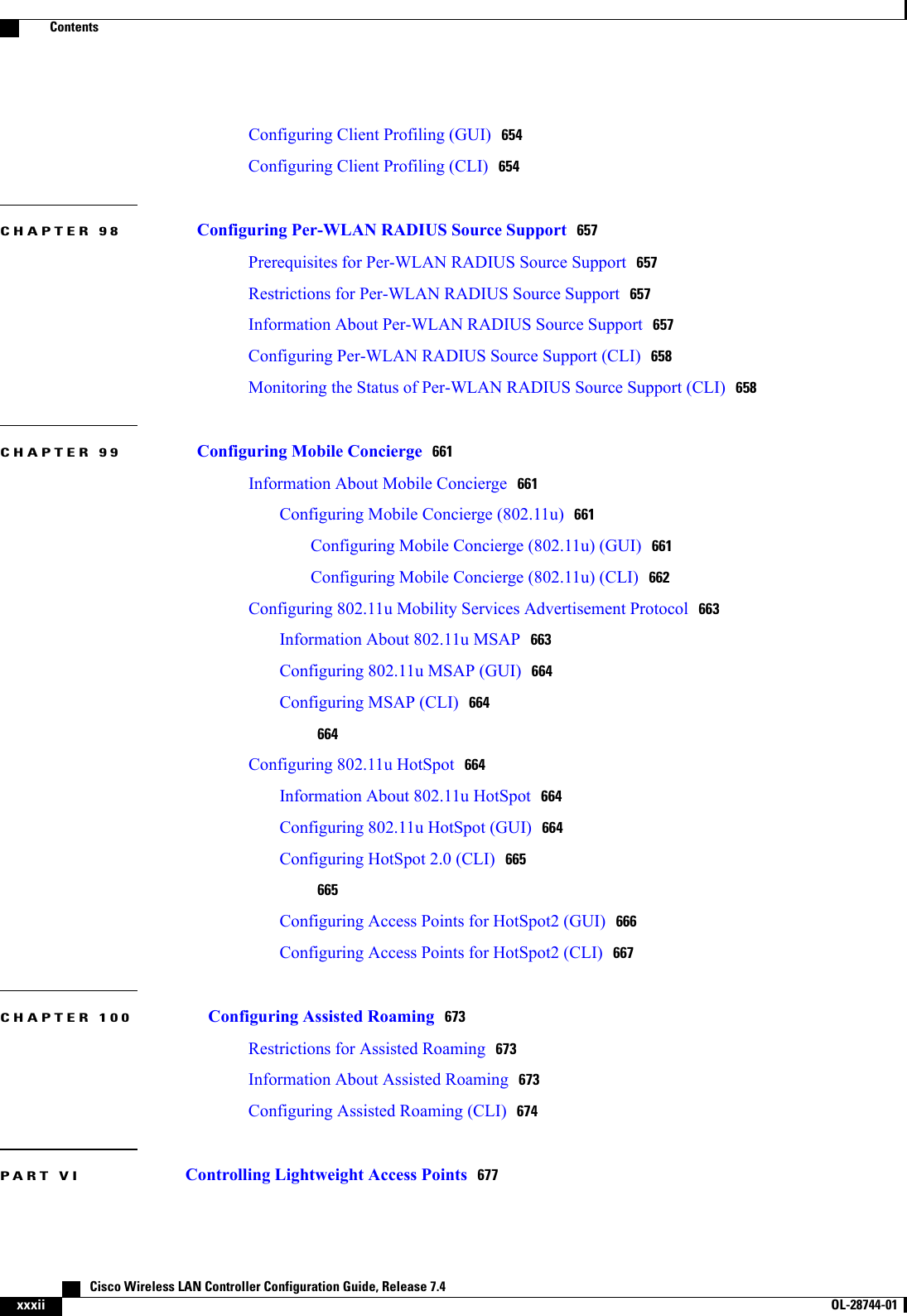
![This figure shows an example of text2pcap output.Figure 31: Sample Text2pcap OutputStep 3 To determine why packets might not be displayed, enter this command:debug packet error {enable |disable}Step 4 To display the status of packet debugging, enter this command:show debug packetInformation similar to the following appears:Status........................................... disabledNumber of packets to display..................... 25Bytes/packet to display.......................... 0Packet display format............................ text2pcapDriver ACL:[1]: disabled[2]: disabled[3]: disabled[4]: disabled[5]: disabled[6]: disabledEthernet ACL:[1]: disabled[2]: disabled[3]: disabled[4]: disabled[5]: disabled[6]: disabledIP ACL:[1]: disabled[2]: disabled[3]: disabled[4]: disabled[5]: disabled[6]: disabledEoIP-Ethernet ACL:[1]: disabled[2]: disabled[3]: disabled[4]: disabled Cisco Wireless LAN Controller Configuration Guide, Release 7.4278 OL-28744-01 Using the Debug Facility](https://usermanual.wiki/Cisco-Systems/102087P.Wireless-LAN-Controller-Configuration-Guide-Part1/User-Guide-2323187-Page-328.png)
![[5]: disabled[6]: disabledEoIP-IP ACL:[1]: disabled[2]: disabled[3]: disabled[4]: disabled[5]: disabled[6]: disabledLWAPP-Dot11 ACL:[1]: disabled[2]: disabled[3]: disabled[4]: disabled[5]: disabled[6]: disabledLWAPP-IP ACL:[1]: disabled[2]: disabled[3]: disabled[4]: disabled[5]: disabled[6]: disabled?Configuring Wireless SniffingInformation About Wireless SniffingThe controller enables you to configure an access point as a network “sniffer,”which captures and forwardsall the packets on a particular channel to a remote machine that runs packet analyzer software. These packetscontain information on time stamps, signal strength, packet sizes, and so on. Sniffers allow you to monitorand record network activity and to detect problems.Prerequisites for Wireless SniffingTo perform wireless sniffing, you need the following hardware and software:•A dedicated access point—An access point configured as a sniffer cannot simultaneously provide wirelessaccess service on the network. To avoid disrupting coverage, use an access point that is not part of yourexisting wireless network.•A remote monitoring device—A computer capable of running the analyzer software.•Windows XP or Linux operating system—The controller supports sniffing on both Windows XP andLinux machines.•Software and supporting files, plug-ins, or adapters—Your analyzer software may require specializedfiles before you can successfully enableRestrictions for Wireless Sniffing•Supported third-party network analyzer software applications are as follows:Cisco Wireless LAN Controller Configuration Guide, Release 7.4 OL-28744-01 279Configuring Wireless Sniffing](https://usermanual.wiki/Cisco-Systems/102087P.Wireless-LAN-Controller-Configuration-Guide-Part1/User-Guide-2323187-Page-329.png)