Cisco Systems 102112 Cisco Aironet 802.11ac Dual Band Access Points User Manual ap1800sgetstart
Cisco Systems Inc Cisco Aironet 802.11ac Dual Band Access Points ap1800sgetstart
Contents
- 1. User Manual AP1800I
- 2. User Manual AP1800S
User Manual AP1800S

GETTING STARTED GUIDE
Cisco Aironet 1800s Network Sensor
First Published: April 5, 2017
2
1About this Guide
2About the Network Sensor
3Safety Instructions
4Unpacking the 1800s Network Sensor
5Ports and Connectors on the 1800s
6Preparing the AP for Installation
6Installation Overview
8Performing a Pre-Installation Configuration
7Mounting and Powering the Network Sensor
8Configuring the Network Sensor for Wireless Service Assurance
8Configuring the Network Sensor for Wireless Service Assurance
12 Checking the Network Sensor LED
13 Miscellaneous Usage and Configuration Guidelines
10 Related Documentation
11 Declarations of Conformity and Regulatory Information
3
1 About this Guide
This guide provides instructions on how to install and configure your Cisco Aironet 1800s Network
Sensor. This guide also provides mounting instructions and limited troubleshooting procedures.
The Cisco Aironet 1800s Network Sensor is referred to as the network sensor, or sensor in this
document.
2 About the Network Sensor
The Cisco Aironet 1800s wireless network sensor is a part of Cisco's Wireless Service Assurance
solution. The Wireless Service Assurance platform has three components, namely, Wireless
Performance Analytics, Real-time Client Troubleshooting, and Proactive Health Assessment.
The Cisco Aironet 1800s network sensor is an 802.11 a/b/g/n/ac (Wave 2) sensor, with internal
antennas, and an Ethernet backhaul. The network sensor can be mounted, in a vertical orientation, on
a wall or a desk, and supports 2x2:2 SS MU-MIMO applications. The sensor is capable of connecting
to a Wireless LAN Controller via CAPWAP, or, joining an infrastructure Access Point as a client. The
sensor can be used to monitor, measure, and troubleshoot overall wired and wireless network
performance.
The 1800s wireless network sensor is available as a base unit with these three power accessory
modules:
• USB adapter module (AIR-MOD-USB-xx)
• AC adapter module (AIR-MOD-AC-xx)
• PoE/Ethernet module (AIR-MOD-POE-xx)
Network Sensor Model Numbers and Regulatory Domains
The Cisco Aironet 1800s network sensor model has the model number format AIR-AP1800S-x-K9,
where the ‘x’ placeholder represents the regulatory domain. The ‘x’ can be any one of the supported
regulatory domains as listed at:
http://www.cisco.com/go/aironet/compliance
4
Network Sensor Features
A full listing of the network sensor's features and specification are provided in the Cisco Aironet 1800s
Network Sensor Data Sheet, at the following URL:
(URL to be added at CCO)
The features of the 1800s network sensors are as follows:
•The only supported mode of operation is as a network sensor for Wireless Service Assurance.
•Two integrated omnidriectional 2.4 GHz single band and 5 GHz single band antennas. Peak
antenna gain is approximately 3 dBi and 5 dBi in 2.4 GHz and 5 GHz bands respectively.
•Radio features supported are:
–
2.4 GHz and 5 GHz concurrent radios
–
2 GHz radio with 2TX x 2RX and two spatial streams SU-MIMO
–
5 GHz radio with 2TX x 2RX 802.11ac Wave 2 capable with two spatial streams SU-MIMO
and MU-MIMO
–
802.11ac based Transmit Beamforming
–
Quality of Service (QoS)
–
Radio Resource Management (RRM)
–
Rogue Detection
–
BandSelect
–
Bluetooth Low Energy 4.0
•Hardware external interfaces:
–
One 10/100/1000 BASE-T (Ethernet) Uplink Interface with inline power capability,
Auto-MDIX (automatically support either straight through or crossover cables), and
802.3af/at PoE.
–
RS-232 console interface, using a custom console cable AIR-MOD-UART-xx.
•Depending on the model of the network sensor and the mounting option chosen, it can be powered
using:
–
USB power 5V, 1.5A.
–
AC power, from Cisco-supplied AC Adapter, providing 120~240VAC, 50~60Hz power.
–
PoE power from a network device supplying 802.3af Class 0 power or greater. You can use
Cisco power injectors AIR-PWRINJ5 (for 802.3af) or AIR-PWRINJ6 (for 802.3at).
For more information on power and mounting options, see XXX.
•Reset button. For information on how to use the Reset button, see “Using the Reset Button”
section on page 25.
5
•One multi-color LED status indicator. See the “Checking the Network Sensor LED” section on
page 18 for information on the colors of the LED status indicator.
- BLE atnenna gain is 1 dBi
6
3 Safety Instructions
Translated versions of the following safety warnings are provided in the translated safety warnings
document that is shipped with your network sensor. The translated warnings are also in the Translated
Safety Warnings for Cisco Aironet Network Sensors, which is available on Cisco.com.
Warning
IMPORTANT SAFETY INSTRUCTIONS
This warning symbol means danger. You are in a situation that could cause bodily injury.
Before you work on any equipment, be aware of the hazards involved with electrical
circuitry and be familiar with standard practices for preventing accidents. Use the
statement number provided at the end of each warning to locate its translation in the
translated safety warnings that accompanied this device.
Statement 1071
SAVE THESE INSTRUCTIONS
Warning
Read the installation instructions before you connect the system to its power source.
Statement 1004
Warning
Installation of the equipment must comply with local and national electrical codes.
Statement 1074
Warning
This product relies on the building’s installation for short-circuit (overcurrent)
protection. Ensure that the protective device is rated not greater than:
20A.
Statement 1005
Warning
Do not operate your wireless network device near unshielded blasting caps or in an
explosive environment unless the device has been modified to be especially qualified for
such use.
Statement 245B
Caution This product and all interconnected equipment must be installed indoors within the same
building, including the associated LAN connections as defined by Environment A of the
IEEE 802.3af/at Standard.

7
Note The network sensor is suitable for use in environmental air space in accordance with section
300.22.C of the National Electrical Code and sections 2-128, 12-010(3), and 12-100 of the
Canadian Electrical Code, Part 1, C22.1. You should not install the power supply or power
injector in air handling spaces.
Note Use only with listed Information Technology Equipment (ITE) equipment. For more
information on ITE equipment, refer to article 645 of the latest National Electrical Code
(NEC).
4 Unpacking the 1800s Network Sensor
To unpack the network sensor, follow these steps:
Step 1 Unpack and remove the network sensor and the mounting accessories, from the shipping box.
Step 2 Return any packing material to the shipping container and save it for future use.
Step 3 Verify that you have received the items listed below. If any item is missing or damaged, contact
your Cisco representative or reseller for instructions.
–
The network sensor base unit.
–
One of the optional power accessory modules, selected when you ordered the network sensor.
These modules be ordered separately also.
8
5 Ports and Connectors on the 1800s
Figure 1 Status LED and Ports Location – Face of the Sensor
1
2
3
4
1Reset button, on the right side of the sensor.
For information on how to use the Reset button, see “Using the Reset Button” section on
page 25.
2
Status LED.
For more information, see the “Network Sensor Status LED” section on page 23.
3Kensington security lock slot, on the right side of the sensor.
4
For the 1800s wireless network sensor having the AIR-MOD-POE-xx PoE/Ethernet module, the
base of the sensor has a USB port and the PoE port (Gigabit Ethernet uplink port).
For the 1800s wireless network sensor having the AIR-MOD-AC-xx EU-specification AC
adapter module, the base of the sensor will have a power on-off switch.
9
Figure 2 Base of the Network Sensor – With AIR-MOD-POE-xx PoE/Ethernet Module
1 2
1
10/100/1000 BASE-T (Ethernet) Uplink
Interface with inline power capability,
Auto-MDIX (automatically support either
straight through or crossover cables), and
802.3af/at PoE-In 2
USB port for powering the sensor, using 5V,
1.5A power.
6 Installation Overview
Installing the network sensor involves these operations:
Step 1 Mounting and Powering the Network Sensor, page 10
Step 2 Configuring the Network Sensor for Wireless Service Assurance, page 22
Step 3 Configuring the Network Sensor for Wireless Service Assurance, page 22

10
7 Mounting and Powering the Network Sensor
Cisco Aironet 1800s series network sensors can be mounted in a vertical orientation, on a wall or desk.
You can also mount the sensor on an electrical or network box. The mounting and powering options
are provided in the following table.
Network Sensor and
Powering Accessory Module Power Supply Option(s) Mounting Option(s)
1800s network sensor with
PoE/Ethernet module
AIR-MOD-POE-xx
• AC power, using the
AC-USB adapter
AIR-MOD-USB, supplying
5V DC, 1.5A power.
• PoE, 802.3af Class 0 power
or greater, from:
–
a network device or
power injector.
–
Cisco power injectors
AIR-PWRINJ5 (for
802.3af) or
AIR-PWRINJ6 (for
802.3at).
Vertical mounting on a wall or
desk, using
AIR-AP-BRACKET-NS.
See the “Mounting the Sensor
using AIR-AP-BRACKET-NS”
section on page 11.
1800s network sensor with USB
adapter module
AIR-MOD-USB-xx
AC power, using the AC-USB
adapter AIR-MOD-USB,
supplying 5V DC, 1.5A power.
1800s network sensor with AC
adapter module
AIR-MOD-AC-xx
AC power from a wall socket
power outlet, through the AC
Adapter module, providing
120~240VAC, 50~60Hz power.
The AC adapter module also
functions as a mounting cradle,
thereby mounting the sensor on
a wall socket power outlet.
See the “Mounting the Sensor
using AIR-MOD-AC-xx
Cradle” section on page 15.

11
Mounting the Sensor using AIR-AP-BRACKET-NS
The Cisco Aironet 1800s wireless sensor can be mounted, in a vertical orientation, on a wall or desk,
to a height of 3 feet, using the wall-mount bracket AIR-AP-BRACKET-NS.
To mount the sensor, follow these instructions:
Step 1 Identify the location for mounting the sensor.
Step 2 Use the wall-mount bracket AIR-AP-BRACKET-NS, as a template to mark the two screw-hole
locations for fastening the bracket to the wall or desk.
Step 3 At the marked locations, drill a hole into the wall or desk.
Step 4 Fasten the AIR-AP-BRACKET-NS to the wall using two 18mm screws.
Step 5 Hold the back of the sensor against the wall, above the bracket, and then slide the sensor
down onto the bracket, till it clicks into place. The hooks on the bracket will click into the
recesses on the back of the sensor.
Step 6 Proceed with connecting the data and power cables.
The sensor can be powered using:
• AC power, using the AC-USB adapter AIR-MOD-USB, supplying 5V DC, 1.5A power.
• PoE, 802.3af Class 0 power or greater, from:
–
a network device or power injector.
–
Cisco power injectors AIR-PWRINJ5 (for 802.3af) or AIR-PWRINJ6 (for 802.3at).
The PoE and USB ports are located on the base of the sensor. When both AC power and PoE power is
available, the PoE power takes precedence.
12
Figure 3 Wall and Desk Mounting Bracket AIR-AP-BRACKET-NS
1
2
2
1
1
Screw holes for fastening the bracket to the
wall or desk.
2
Hooks which click into the recesses on the
back the sensor, for mounting the sensor on
the bracket.
13
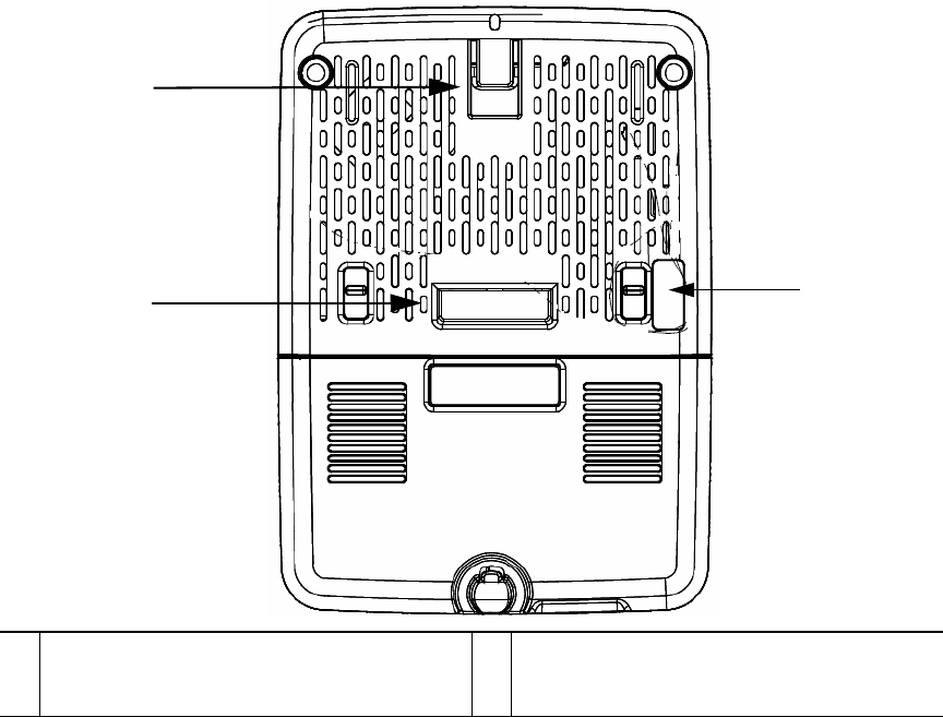
Figure 4 Back of the Sensor – With PoE/Ethernet Module AIR-MOD-POE-xx
1
12
1
Recesses on the back of the sensor into which
the hooks on the wall-mount bracket slide
and click into place. 2
RS-232 console interface port, hidden under
a mylar label. You need to use the custom
console cable AIR-MOD-UART-xx.
14
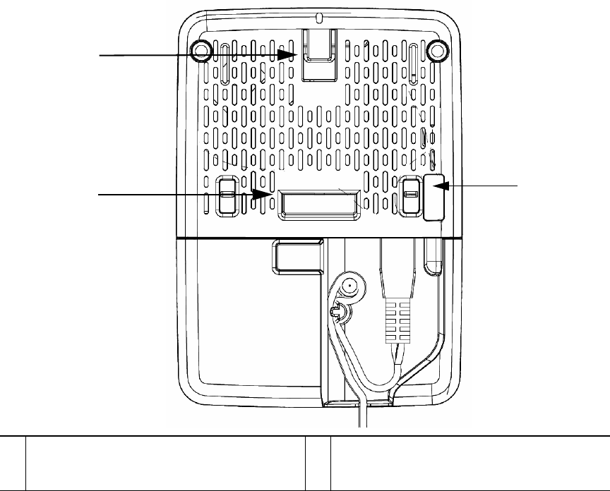
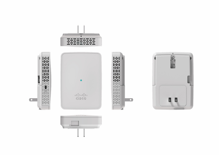
Figure 5 Back of the Sensor – With USB adapter module AIR-MOD-USB-xx
1
12
1
Recesses on the back of the sensor into which
the hooks on the wall-mount bracket slide
and click into place. 2
RS-232 console interface port, hidden under
a mylar label. You need to use the custom
console cable AIR-MOD-UART-xx.
15
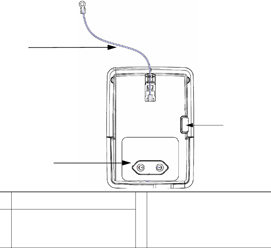
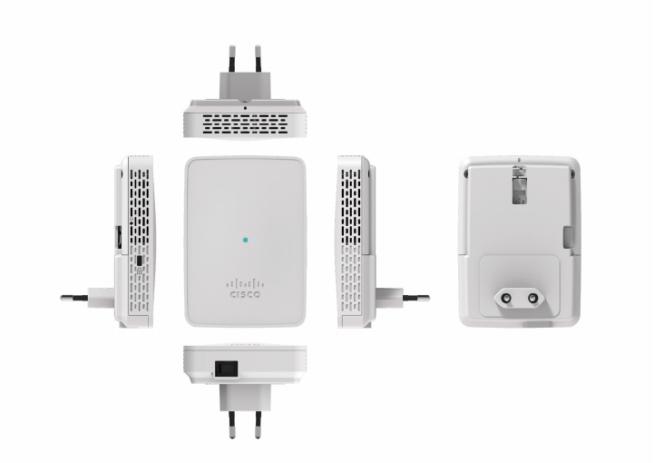
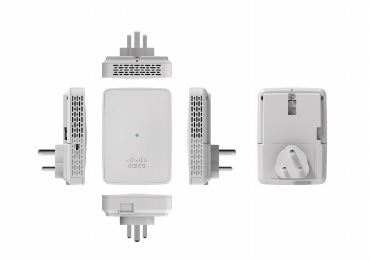
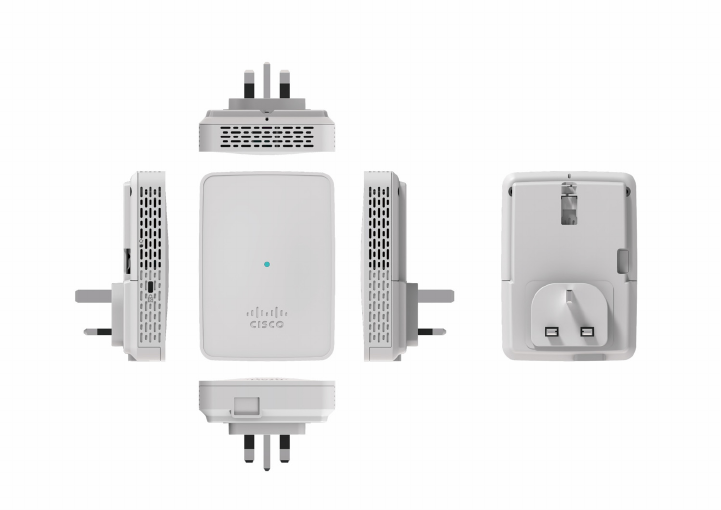
Mounting the Sensor using AIR-MOD-AC-xx Cradle
The AIR-MOD-AC-xx AC adapter module also functions as a mounting cradle, using which you can
plug-in (and thereby, mount) the sensor into a wall socket power outlet. You can additionally secure
the sensor by fasting the security wire to the wall or desk.
Figure 6 Back of the Sensor – With AC Adapter Module AIR-MOD-AC-xx
1
3
2
1
Security wire which can be used to secure the
sensor by fastening it to the wall.
3
EU-specification AC adapter module
AIR-MOD-AC-xx.
The AC adapter module/cradle provided
differs in design according to regional power
supply standards. See the“AC Cradle
Options for Different Power Supply
Standards and Regions” section on page 16.
2
RS-232 console interface port, hidden under
a mylar label. You need to use the custom
console cable AIR-MOD-UART-xx.
16
AC Cradle Options for Different Power Supply Standards and Regions
Figure 7 Sensor with AC Cradle for AU Region

17
Figure 8 Sensor with AC Cradle for CN Region
18
Figure 9 Sensor with AC Cradle for EU Region
19
Figure 10 Sensor with AC Cradle for SA Region
20
Figure 11 Sensor with AC Cradle for UK Region
21
Figure 12 Sensor with AC Cradle for US Region
22
8 Configuring the Network Sensor for Wireless Service
Assurance
The Cisco Aironet 1800s wireless network sensors are configured and managed by Cisco wireless LAN
controllers. The wireless LAN controller manages network sensors in the same manner as it manages
Lightweight Access Points. The controller also:
• Collect stats and data from Network Sensors, Infrastructure APs and Clients and display real time
information from the data collected.
• Interfaces with Cisco Cloud Service to send the collected data at regular intervals, to enable the
cloud service to display historical information about the wireless network health.
Each network sensor establishes a management and control connection to a Wireless LAN Controller
over the intermediate Ipv4/Ipv6 network.
The wireless LAN controller operates as a control center that determines the current task for each
network sensor. In addition to configuring network sensors, the controller also collects, aggregates,
parses, and presents statistics and results returned from each network sensor.
The wireless LAN controller uses the data from the sensor for basic connectivity troubleshooting, RF
performance troubleshooting, and Wireless QoE troubleshooting. The controller also periodically
sends wireless network information to the Cisco Cloud Service's Performance Analytics function. The
cloud-based Network Assurance Collector collects historical network assurance data, which is
scheduled by the controller and collected by the network sensors.
For information on configuring the network sensor and on the role of the wireless LAN controller in
Wireless Service Assurance, see the following guide:
(To be added at CCO/FCS)
For more information on the role of the Cisco Cloud Service in Wireless Service Assurance, see the
following guide:
(To be added at CCO/FCS)
23
9 Troubleshooting and Resetting the Network Sensor
Network Sensor Status LED
Note It is expected that there will be small variations in the LED color intensity and hue from unit
to unit. This is within the normal range of the LED manufacturer’s specifications and is not a
defect.
The network sensor status LED indicates various conditions which are described in Table 1.
Ta b l e 1 LED Status Indications
Message
Type
LED State Message
Meaning
Boot loader status
sequence
Blinking Green DRAM memory test in progress
DRAM memory test OK
Board initialization in progress
Initializing FLASH file system
FLASH memory test OK
Initializing Ethernet
Ethernet OK
Starting the operating system of the sensor
Initialization successful
Association status Chirping Green Normal operating condition, but no wireless
client associated
Green Normal operating condition with at least one
wireless client association
Operating status Blinking Amber Software upgrade is in progress.
Cycling through Green,
Red, and Amber
Discovery/join process is in progress.
Rapidly cycling
through Red, Green,
Amber, and off.
Access point location command invoked from
controller web interface.
Blinking Red Ethernet link is not operational.

24
Ethernet Port LEDs
The Ethernet port has two LEDs for showing Link (Green) and Activity (Amber) statuses. They are
integrated on the RJ45 connector. For a description of the statuses they indicate, see the following
table.
10M
Link
10M
Active
100M
Link
100M
Active
1000M
Link
1000M
Active
Link (Green) LED State Off Off Off Off On On
Activity (Amber) LED State On Blinking On Blinking On Blinking
Boot loader warnings Blinking Amber Configuration recovery in progress (Reset button
pushed for 2 to 3 seconds)
Red Ethernet failure or image recovery (Reset button
pushed for 20 to 30 seconds)
Blinking Green Image recovery in progress (Reset button
released)
Boot loader errors Red DRAM memory test failure
Blinking Red and
Amber
FLASH file system failure
Blinking Red and off One of the following:
• Environment variable failure
• Bad MAC address
• Ethernet failure during image recovery
• Boot environment failure
• No Cisco image file
• Boot failure
Cisco Network Sensor
Operating System
errors
Red Software failure; try disconnecting and
reconnecting unit power
Cycling through Red,
Green, Amber and off.
General warning; insufficient inline power
Table 1 LED Status Indications (continued)
Message
Type
LED State Message
Meaning
25
Using the Reset Button
Using the Reset button (see Figure 2) you can:
• Reset the network sensor to it’s default factory-shipped configuration.
• Clear the network sensor internal storage, including all configuration files and the regulatory
domain configuration.
To use the Reset button, press, and keep pressed, the Reset button on the network sensor during the
network sensor boot cycle. Wait until the status LED changes to Amber. Then:
• To reset the network sensor to the default factory-shipped configuration, keep the Reset button
pressed for less than 20 seconds. The network sensor configuration files are cleared.
This resets all configuration settings to factory defaults, including passwords, encryption keys, the
IP address, and the SSID.
• To clear the network sensor internal storage, including all configuration files and the regulatory
domain configuration, keep the Reset button pressed for more than 20 seconds, but less than 60
seconds.
The network sensor status LED changes from Amber to Red, and all the files in the network sensor
storage directory are cleared.
If you keep the Reset button pressed for more than 60 seconds, the Reset button is assumed faulty and
no changes are made.
10 Related Documentation
All user documentation for the Cisco Aironet 1800s series network sensor is available at the following
URL:
(To be added at CCO/FCS)
For detailed information and guidelines for configuring and deploying your network sensor in a
wireless network, see the Cisco Wireless LAN Controller Configuration Guide, at the following URL:
(To be added at CCO/FCS)

26
11 Declarations of Conformity and Regulatory Information
This section provides declarations of conformity and regulatory information for the Cisco Aironet
1800s Network Sensor. You can find additional information at this URL:
www.cisco.com/go/aironet/compliance
Manufacturers Federal Communication Commission Declaration of
Conformity Statement
Tested To Comply
With FCC Standards
FOR HOME OR OFFICE USE
Network Sensor Models Certification Number
AIR-AP1800S-B-K9 LDK102108
Manufacturer:
Cisco Systems, Inc.
170 West Tasman Drive
San Jose, CA 95134-1706
USA
This device complies with Part 15 rules. Operation is subject to the following two conditions:
1. This device may not cause harmful interference, and
2. This device must accept any interference received, including interference that may cause undesired
operation.
This equipment has been tested and found to comply with the limits of a Class B digital device,
pursuant to Part 15 of the FCC Rules. These limits are designed to provide reasonable protection
against harmful interference when the equipment is operated in a residential environment. This
equipment generates, uses, and radiates radio frequency energy, and if not installed and used in
accordance with the instructions, may cause harmful interference. However, there is no guarantee that
27
interference will not occur. If this equipment does cause interference to radio or television reception,
which can be determined by turning the equipment off and on, the user is encouraged to correct the
interference by one of the following measures:
• Reorient or relocate the receiving antenna.
• Increase separation between the equipment and receiver.
• Connect the equipment to an outlet on a circuit different from which the receiver is connected.
• Consult the dealer or an experienced radio/TV technician.
Caution The Part 15 radio device operates on a non-interference basis with other devices operating
at this frequency when using the integrated antennas. Any changes or modification to the
product not expressly approved by Cisco could void the user’s authority to operate this
device.
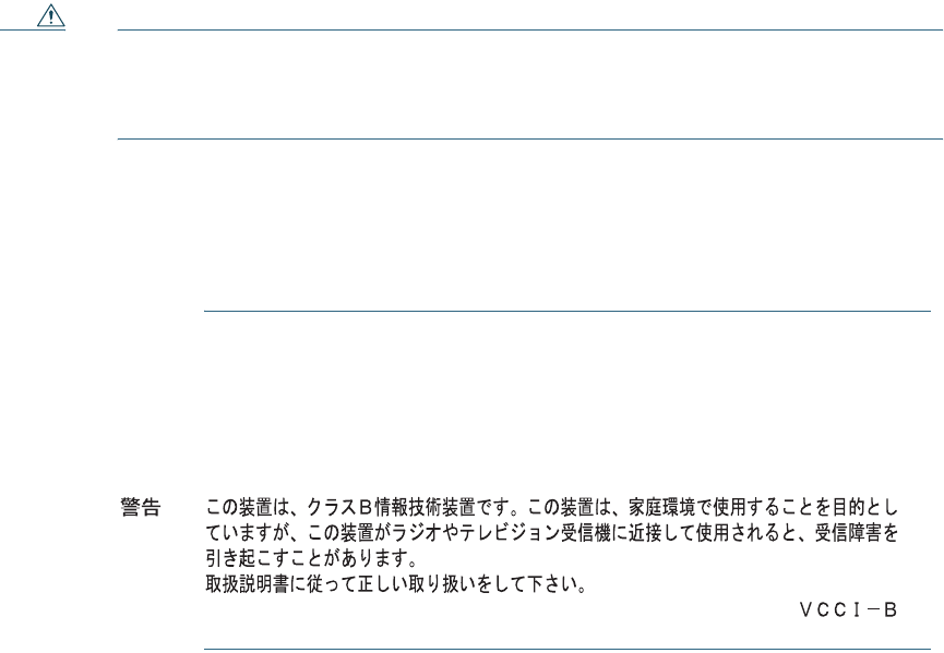
VCCI Statement for Japan
Warning
This is a Class B product based on the standard of the Voluntary Control
Council for Interference from Information Technology Equipment (VCCI). If this
is used near a radio or television receiver in a domestic environment, it may
cause radio interference. Install and use the equipment according to the
instruction manual.
28
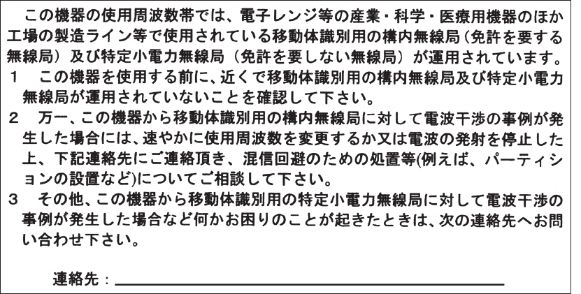
Guidelines for Operating Cisco Aironet Network Sensors in Japan
This section provides guidelines for avoiding interference when operating Cisco Aironet network
sensors in Japan. These guidelines are provided in both Japanese and English.
Japanese Translation
03-6434-6500
208697
English Translation
This equipment operates in the same frequency bandwidth as industrial, scientific, and medical devices
such as microwave ovens and mobile object identification (RF-ID) systems (licensed premises radio
stations and unlicensed specified low-power radio stations) used in factory production lines.
1. Before using this equipment, make sure that no premises radio stations or specified low-power
radio stations of RF-ID are used in the vicinity.
2. If this equipment causes RF interference to a premises radio station of RF-ID, promptly change
the frequency or stop using the device; contact the number below and ask for recommendations
on avoiding radio interference, such as setting partitions.
3. If this equipment causes RF interference to a specified low-power radio station of RF-ID, contact
the number below.
Contact Number: 03-6434-6500
29
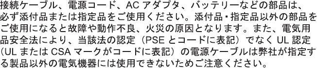
Statement 371—Power Cable and AC Adapter
English Translation
When installing the product, please use the provided or designated connection cables/power cables/AC
adaptors. Using any other cables/adaptors could cause a malfunction or a fire. Electrical Appliance and
Material Safety Law prohibits the use of UL-certified cables (that have the “UL” shown on the code)
for any other electrical devices than products designated by CISCO. The use of cables that are certified
by Electrical Appliance and Material Safety Law (that have “PSE” shown on the code) is not limited
to CISCO-designated products.
30
Industry Canada
Network Sensor Models Certification Number
AIR-AP1800S-A-K9 2461B-102108
Canadian Compliance Statement
This device complies with Industry Canada licence-exempt RSS standard(s). Operation is subject to
the following two conditions: (1) this device may not cause interference, and (2) this device must
accept any interference, including interference that may cause undesired operation of the device.
Le présent appareil est conforme aux CNR d'Industrie Canada applicables aux appareils radio
exempts de licence. L'exploitation est autorisée aux deux conditions suivantes : (1) l'appareil ne doit
pas produire de brouillage, et (2) l'utilisateur de l'appareil doit accepter tout brouillage radioélectrique
subi, même si le brouillage est susceptible d'en compromettre le fonctionnement.
Under Industry Canada regulations, this radio transmitter may only operate using an antenna of a type
and maximum (or lesser) gain approved for the transmitter by Industry Canada. To reduce potential
radio interference to other users, the antenna type and its gain should be so chosen that the equivalent
isotropically radiated power (e.i.r.p.) is not more than that necessary for successful communication.
Conformément à la réglementation d'Industrie Canada, le présent émetteur radio peut fonctionner
avec une antenne d'un type et d'un gain maximal (ou inférieur) approuvé pour l'émetteur par Industrie
Canada. Dans le but de réduire les risques de brouillage radioélectrique à l'intention des autres
utilisateurs, il faut choisir le type d'antenne et son gain de sorte que la puissance isotrope rayonnée
équivalente (p.i.r.e.) ne dépasse pas l'intensité nécessaire à l'établissement d'une communication
satisfaisante.
This radio transmitter has been approved by Industry Canada to operate with the antenna types listed
below with the maximum permissible gain and required antenna impedance for each antenna type
indicated. Antenna types not included in this list, having a gain greater than the maximum gain
indicated for that type, are strictly prohibited for use with this device.
Le présent émetteur radio a été approuvé par Industrie Canada pour fonctionner avec les types
d'antenne énumérés ci-dessous et ayant un gain admissible maximal et l'impédance requise pour
chaque type d'antenne. Les types d'antenne non inclus dans cette liste, ou dont le gain est supérieur au
gain maximal indiqué, sont strictement interdits pour l'exploitation de l'émetteur.
Antenna Type Antenna Gain Antenna Impedance
Dual-band Omni 3/5 dBi 50 ohms
31
Operation in the band 5150-5250 MHz is only for indoor use to reduce the potential for harmful
interference to co-channel mobile satellite systems.
La bande 5 150-5 250 MHz est réservés uniquement pour une utilisation à l'intérieur afin de réduire
les risques de brouillage préjudiciable aux systèmes de satellites mobiles utilisant les mêmes canaux.
Users are advised that high-power radars are allocated as primary users (i.e. priority users) of the
bands 5250-5350 MHz and 5650-5850 MHz and that these radars could cause interference and/or
damage to LE-LAN devices.
Les utilisateurs êtes avisés que les utilisateurs de radars de haute puissance sont désignés utilisateurs
principaux (c.-à-d., qu'ils ont la priorité) pour les bandes 5 250-5 350 MHz et 5 650-5 850 MHz et
que ces radars pourraient causer du brouillage et/ou des dommages aux dispositifs LAN-EL.
European Community, Switzerland, Norway, Iceland, and
Liechtenstein
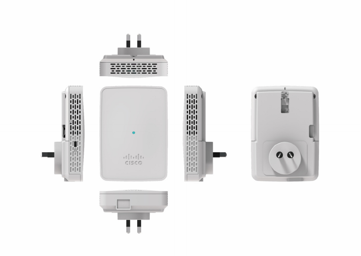
Network Sensor Models:
AIR-AP1800S-E-K9
32
Declaration of Conformity with regard to the R&TTE Directive
1999/5/EC & Medical Directive 93/42/EEC
33
The following standards were applied:
EMC—EN 301.489-1 v1.9.2; EN 301.489-17 v2.2.1
Health & Safety—EN60950-1: 2006; EN 50385: 2002
Radio—EN 300 328 v 1.8.1; EN 301.893 v 1.7.1
The conformity assessment procedure referred to in Article 10.4 and Annex III of Directive 1999/5/EC
has been followed.

This device also conforms to the EMC requirements of the Medical Devices Directive 93/42/EEC.
Note This equipment is intended to be used in all EU and EFTA countries. Outdoor use may be
restricted to certain frequencies and/or may require a license for operation. For more details,
contact Cisco Corporate Compliance.
The product carries the CE Mark:
Declaration of Conformity for RF Exposure
This section contains information on compliance with guidelines related to RF exposure.
Generic Discussion on RF Exposure
The Cisco products are designed to comply with the following national and international standards on
Human Exposure to Radio Frequencies:
• US 47 Code of Federal Regulations Part 2 Subpart J
• American National Standards Institute (ANSI) / Institute of Electrical and Electronic Engineers /
IEEE C 95.1 (99)
• International Commission on Non Ionizing Radiation Protection (ICNIRP) 98
• Ministry of Health (Canada) Safety Code 6. Limits on Human Exposure to Radio Frequency Fields
in the range from 3kHz to 300 GHz
• Australia Radiation Protection Standard
To ensure compliance with various national and international Electromagnetic Field (EMF) standards,
the system should only be operated with Cisco approved accessories.
This Device Meets International Guidelines for Exposure to Radio Waves
The 1800s network sensor device includes a radio transmitter and receiver. It is designed not to exceed
the limits for exposure to radio waves (radio frequency electromagnetic fields) recommended by
international guidelines. The guidelines were developed by an independent scientific organization
(ICNIRP) and include a substantial safety margin designed to ensure the safety of all persons,
regardless of age and health.
35
As such the systems are designed to be operated as to avoid contact with the antennas by the end user.
It is recommended to set the system in a location where the antennas can remain at least a minimum
distance as specified from the user in accordance to the regulatory guidelines which are designed to
reduce the overall exposure of the user or operator.
Separation Distance
MPE Distance Limit
0.06 mW/cm220 cm (7.87 inches) 1.00 mW/cm2
The World Health Organization has stated that present scientific information does not indicate the
need for any special precautions for the use of wireless devices. They recommend that if you are
interested in further reducing your exposure then you can easily do so by reorienting antennas away
from the user or placing he antennas at a greater separation distance then recommended.
This Device Meets FCC Guidelines for Exposure to Radio Waves
The 1800s network sensor device includes a radio transmitter and receiver. It is designed not to exceed
the limits for exposure to radio waves (radio frequency electromagnetic fields) as referenced in FCC
Part 1.1310. The guidelines are based on IEEE ANSI C 95.1 (92) and include a substantial safety
margin designed to ensure the safety of all persons, regardless of age and health.
As such the systems are designed to be operated as to avoid contact with the antennas by the end user.
It is recommended to set the system in a location where the antennas can remain at least a minimum
distance as specified from the user in accordance to the regulatory guidelines which are designed to
reduce the overall exposure of the user or operator.
The device has been tested and found compliant with the applicable regulations as part of the radio
certification process.
Separation Distance
MPE Distance Limit
0.60mW/cm220 cm (7.87 inches) 1.00 mW/cm2
The US Food and Drug Administration has stated that present scientific information does not indicate
the need for any special precautions for the use of wireless devices. The FCC recommends that if you
are interested in further reducing your exposure then you can easily do so by reorienting antennas
away from the user or placing the antennas at a greater separation distance then recommended or
lowering the transmitter power output.

36
This Device Meets the Industry Canada Guidelines for Exposure to Radio
Waves
The 1800s network sensor device includes a radio transmitter and receiver. It is designed not to exceed
the limits for exposure to radio waves (radio frequency electromagnetic fields) as referenced in Health
Canada Safety Code 6. The guidelines include a substantial safety margin designed into the limit to
ensure the safety of all persons, regardless of age and health.
As such the systems are designed to be operated as to avoid contact with the antennas by the end user.
It is recommended to set the system in a location where the antennas can remain at least a minimum
distance as specified from the user in accordance to the regulatory guidelines which are designed to
reduce the overall exposure of the user or operator.
Separation Distance
Frequency MPE Distance Limit
2.4 GHz 0.17 W/m220 cm (7.87 inches) 5.4 W/m2
5 GHz 0.66 W/m29.2 W/m2
Health Canada states that present scientific information does not indicate the need for any special
precautions for the use of wireless devices. They recommend that if you are interested in further
reducing your exposure you can easily do so by reorienting antennas away from the user, placing the
antennas at a greater separation distance than recommended, or lowering the transmitter power
output.
Cet appareil est conforme aux directives internationales en matière
d'exposition aux fréquences radioélectriques
Cet appareil de la gamme 1800s comprend un émetteur-récepteur radio. Il a été conçu de manière à
respecter les limites en matière d'exposition aux fréquences radioélectriques (champs
électromagnétiques de fréquence radio), recommandées dans le code de sécurité 6 de Santé Canada.
Ces directives intègrent une marge de sécurité importante destinée à assurer la sécurité de tous,
indépendamment de l'âge et de la santé.
Par conséquent, les systèmes sont conçus pour être exploités en évitant que l'utilisateur n'entre en
contact avec les antennes. Il est recommandé de poser le système là où les antennes sont à une distance
minimale telle que précisée par l'utilisateur conformément aux directives réglementaires qui sont
conçues pour réduire l'exposition générale de l'utilisateur ou de l'opérateur.

Distance d'éloignement
Fréquence MPE Distance Limite
2.4 GHz 0.17 W/m220 cm (7.87 inches) 5.4 W/m2
5 GHz 0.66 W/m29.2 W/m2
37
Santé Canada affirme que la littérature scientifique actuelle n'indique pas qu'il faille prendre des
précautions particulières lors de l'utilisation d'un appareil sans fil. Si vous voulez réduire votre
exposition encore davantage, selon l'agence, vous pouvez facilement le faire en réorientant les antennes
afin qu'elles soient dirigées à l'écart de l'utilisateur, en les plaçant à une distance d'éloignement
supérieure à celle recommandée ou en réduisant la puissance de sortie de l'émetteur.
Additional Information on RF Exposure
You can find additional information on the subject at the following links:
•Cisco Systems Spread Spectrum Radios and RF Safety white paper at this URL:
http://www.cisco.com/warp/public/cc/pd/witc/ao340ap/prodlit/rfhr_wi.htm
•FCC Bulletin 56: Questions and Answers about Biological Effects and Potential Hazards of Radio
Frequency Electromagnetic Fields
•FCC Bulletin 65: Evaluating Compliance with the FCC guidelines for Human Exposure to Radio
Frequency Electromagnetic Fields
You can obtain additional information from the following organizations:
•World Health Organization Internal Commission on Non-Ionizing Radiation Protection at this
URL: www.who.int/emf
•United Kingdom, National Radiological Protection Board at this URL: www.nrpb.org.uk
•Cellular Telecommunications Association at this URL: www.wow-com.com
•The Mobile Manufacturers Forum at this URL: www.mmfai.org
Administrative Rules for Cisco Aironet Network Sensors in Taiwan
This section provides administrative rules for operating Cisco Aironet network sensors in Taiwan. The
rules for all network sensors are provided in both Chinese and English.
38
Chinese Translation
English Translation
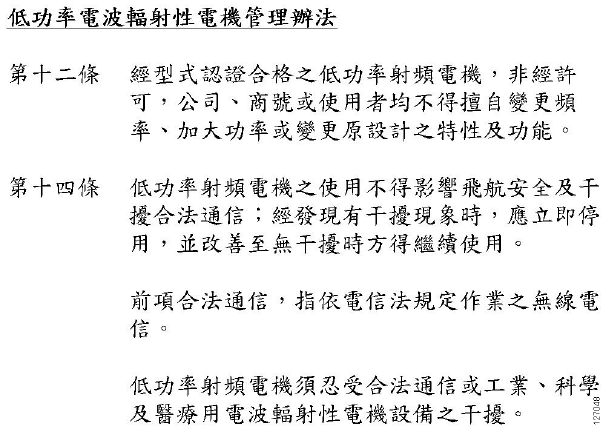
Administrative Rules for Low-power Radio-Frequency Devices
Article 12
For those low-power radio-frequency devices that have already received a type-approval, companies,
business units or users should not change its frequencies, increase its power or change its original
features and functions.
Article 14
The operation of the low-power radio-frequency devices is subject to the conditions that no harmful
interference is caused to aviation safety and authorized radio station; and if interference is caused, the
user must stop operating the device immediately and can't re-operate it until the harmful interference
is clear.
The authorized radio station means a radio-communication service operating in accordance with the
Communication Act.
The operation of the low-power radio-frequency devices is subject to the interference caused by the
operation of an authorized radio station, by another intentional or unintentional radiator, by
industrial, scientific and medical (ISM) equipment, or by an incidental radiator.
Chinese Translation
40
English Translation
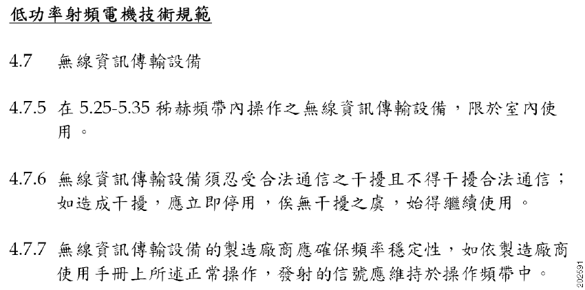
Low-power Radio-frequency Devices Technical Specifications
4.7 Unlicensed National Information Infrastructure
4.7.5 Within the 5.25-5.35 GHz band, U-NII devices will be restricted to indoor operations to
reduce any potential for harmful interference to co-channel MSS operations.
4.7.6 The U-NII devices shall accept any interference from legal communications and shall not
interfere the legal communications. If interference is caused, the user must stop operating
the device immediately and can't re-operate it until the harmful interference is clear.
4.7.7 Manufacturers of U-NII devices are responsible for ensuring frequency stability such that
an emission is maintained within the band of operation under all conditions of normal
operation as specified in the user manual.
Operation of Cisco Aironet Network Sensors in Brazil
This section contains special information for operation of Cisco Aironet network sensors in Brazil.
Network Sensor Models:
AIR-AP1800S-Z-K9
Figure 13 Brazil Regulatory Information

41
Portuguese Translation
Este equipamento opera em caráter secundário, isto é, não tem direito a proteção contra interferência
prejudicial, mesmo de estações do mesmo tipo, e não pode causar interferência a sistemas operando
em caráter primário.
English Translation
This equipment operates on a secondary basis and consequently must accept harmful interference,
including interference from stations of the same kind. This equipment may not cause harmful
interference to systems operating on a primary basis.
Declaration of Conformity Statements
All the Declaration of Conformity statements related to this product can be found at the following
location: http://www.ciscofax.com
12 Obtaining Documentation and Submitting a Service
Request
For information on obtaining documentation, using the Cisco Bug Search Tool (BST), submitting a
service request, and gathering additional information, see What’s New in Cisco Product
Documentation.
To receive new and revised Cisco technical content directly to your desktop, you can subscribe to
the What’s New in Cisco Product Documentation RSS feed. The RSS feeds are a free service.
© 2017 Cisco Systems, Inc. All rights reserved.
Cisco and the Cisco logo are trademarks or registered trademarks of Cisco and/or its affiliates in the U.S. and other countries. To view a list of Cisco trademarks,
go to this URL: www.cisco.com/go/trademarks. Third-party trademarks mentioned are the property of their respective owners. The use of the word partner does
not imply a partnership relationship between Cisco and any other company. (1110R)
42