Cisco Systems 2500-BTS2-R1 Base Station Transmitter User Manual Ripwave Base Station I C Guide
Cisco Systems, Inc Base Station Transmitter Ripwave Base Station I C Guide
user manual
Navini Networks, Inc. Ripwave Base Station I&C Guide
21
Chapter 1: Overview
Ripwave Description
A Ripwave system has three main components: the Base Station, the Modems, and the Element
Management System (EMS). The Base Station performs the Modem registration and call
processing, and provides the interface between the backhaul network and the EMS. It is made up
of the Base Transceiver Station (BTS) and the Radio Frequency Subsystem (RFS) (Figures 1, 2
& 3). This manual provides the guidelines and instructions for installing and commissioning
(I&C) the Base Station.
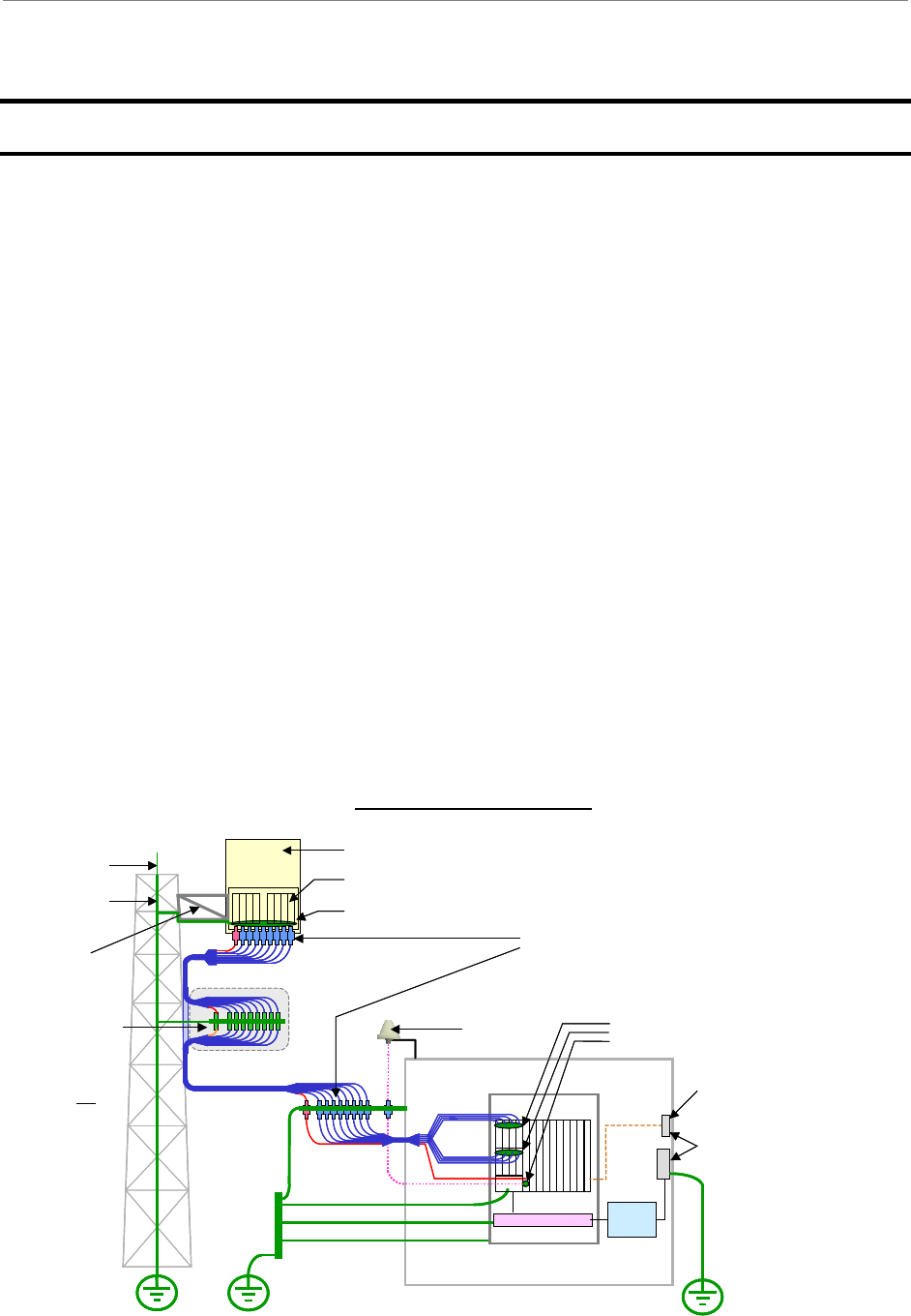
Figure 1 shows the system with both Secondary (built-in) and Primary (optional) Lightning
Protection. Lightning Protection helps to protect the RFS, the BTS, and the RF lines against
“tower lightning” events occurring at the Base Station. The customer must exercise judgment
when balancing risk against cost to decide whether to install the primary protection kit at an extra
cost or to rely on the secondary protection only. NOTE: Navini does not warranty equipment
against lightning strikes.
In addition to tower lightning events occurring at the base station, lightning events that occur
miles away from the BTS could generate intense electrical currents traveling over the power
and/or backhaul lines and into the BTS equipment, damaging it. For this reason, Navini
recommends adding surge protection devices at the power and backhaul demarcation points.
Figure 1: TTA Configuration with Primary and Secondary Surge Protection
CAL
Digital Shelf
Rectifiers (24 VDC, 60 A)
Frame
GPS
GPS
Antenna Secondary (Built-in)
Surge Protectors
RF Ethernet
110/220 VAC
60/50 Hz
Demarc. Points
Omni or Panel Antenna
Power Amplifiers
Secondary (Built-in)
Surge Protectors
Lightning
Ground
Antenna
Bracket
Primary Surge Protectors
(Use Polyphasor surge protectors
with the CAL Cable and Huber+Suhner
surge protectors everywhere else)
Additional
grounding block
needed if main
cable run
exceeds 250 ft
(75 m)
These are not
Surge Protectors
but N-type/Female
to N-type/Female
bulhhead
connectors for
grounding
5 Ohm
maximum
Use
"Smart Jack"
for surge
protection!!!
Rectifier
Surge
Protection
Device
Surge
Protection
Device
Navini Networks, Inc. Ripwave Base Station I&C Guide
22
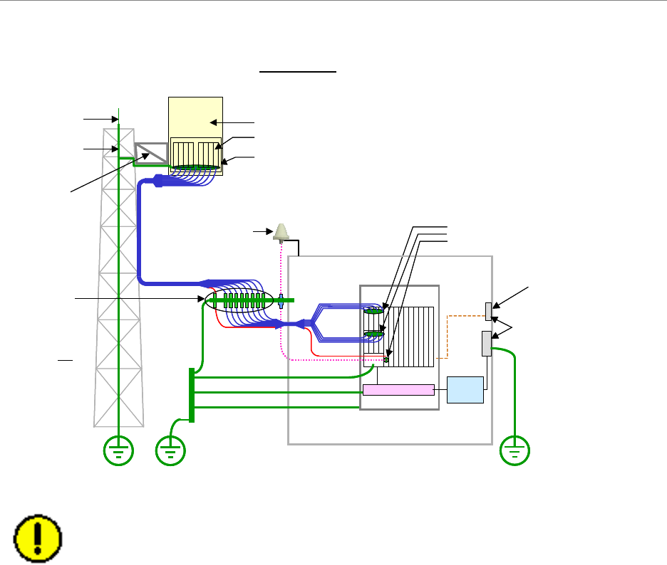
Figure 2: TTA Configuration with Secondary Surge Protection Only
CAUTION! Although Secondary surge protection is built into the TTA that
ships from the factory, Navini recommends that the Primary surge protection kit
be purchased and installed, in particular if the equipment is installed in an area
where electrical storms are common. Surge protection devices should be added
in front of the rectifier. Lightning striking miles away from the BTS may cause
an intense electric current traveling on the power and/or backhaul lines and into
the BTS, damaging the equipment.
Power Amplifiers
Secondary (Built-in) Surge Protectors
Omni or Panel Antenna
Lightning
Ground
Secondary (Built-in)
Surge Protectors
GPS Antenna
Digital Shelf
Rectifiers (24 VDC, 60 A)
Frame
CAL
Antenna
Bracket
14 dB
max
GPS
5 Ohm
maximum
Demarc. Points
Ethernet
110/220 VAC
60/50 Hz
Use
"Smart Jack"
for surge
protection!!!
Rectifier
Surge
Protection
Device
RF
MAY BE
NEEDED
DEPENDING
ON THE
COUNTRY OR
CITY BUILDING
CODES
These are not
Surge Protectors
but N-
type/Female to
N-type/Female
bulhhead
connectors for
grounding
Power Amplifiers
Secondary (Built-in) Surge Protectors
Omni or Panel Antenna
Lightning
Ground
Secondary (Built-in)
Surge Protectors
GPS Antenna
Digital Shelf
Rectifiers (24 VDC, 60 A)
Frame
CAL
Antenna
Bracket
14 dB
max
GPS
5 Ohm
maximum
Demarc. Points
Ethernet
110/220 VAC
60/50 Hz
Use
"Smart Jack"
for surge
protection!!!
Rectifier
Surge
Protection
Device
Surge
Protection
Device
RF
MAY BE
NEEDED
DEPENDING
ON THE
COUNTRY OR
CITY BUILDING
CODES
These are not
Surge Protectors
but N-
type/Female to
N-type/Female
bulhhead
connectors for
grounding

Navini Networks, Inc. Ripwave Base Station I&C Guide
23
Procedural Documents & Forms
You will refer to other Ripwave documents, procedures, and forms in the process of installing
and commissioning the Base Station. The product documentation is provided on the Ripwave
Standard Documentation CD (Table 1). As well, the EMS manuals can be viewed on-line
through the EMS Server and Client applications.
Table 1: Ripwave Standard Documentation CD
Order Number 95-00116-00 Part Number
EMS Overview Manual 40-00016-03
EMS Software Installation Guide 40-00017-00
EMS-OSS Integration Guide 40-00147-00
EMS Administration Guide 40-00031-00
Ripwave Configuration Guide 40-00016-01
Excel Configuration Form 44-00032-01
EMS CLI Reference Manual 40-00016-02
Ripwave Alarm Resolution Reference Manual 40-00033-00
System Operations, Maintenance & Troubleshooting Guide* 00-00046-00
EMS Diagnostic Tools Guide 40-00032-00
Ripwave Modem Quick Installation Guide 40-00112-00
English 40-00098-00
Spanish 40-00096-00
Ripwave Modem User Guide 40-00111-00
English 40-00097-00
Spanish 40-00099-00
Ripwave Modem Software Update Tool Quick Guide 40-00066-00
Customer Release Notes Varies w/each release
*Available 2Q04
A number of other forms are used in the installation and commissioning process. This I&C
Guide references those throughout, and provides copies in the appendices.
High-level I&C Process
To put the I&C activities in the context of overall system deployment, Figure 4 provides a ‘flow’
of the key activities that are performed prior to and during the installation and commissioning of
the Ripwave Base Station. Post-I&C, the system that has been installed and commissioned goes
through Acceptance Testing against the customer’s objectives for that site. Once customer sign-
off on the site is achieved, the customer becomes fully responsible for operating the system. You
may find this flowchart can be used as a helpful checklist during the process.

Navini Networks, Inc. Ripwave Base Station I&C Guide
24
Different job holders may perform various portions of these activities and not necessarily all of
the activities. In fact, Marketing and Engineering personnel typically handle the earlier tasks,
while installation may be a stand-alone function. Commissioning may or may not be handled by
the same people who designed or installed the site. Regardless of who does them, these key
activities have to be accomplished for successful deployment:
• Site Selection, Design, and Preparation
• Physical Installation
• Commissioning, with Acceptance Testing and Sign-off
Prior to installation, Navini and the customer formulate a Project Plan and Responsibility
Assignment Matrix (RAM) to clarify who will do what to complete the I&C activities. If
requested by the customer, Navini may provide personnel, procedures, forms, and/or tools
required to install and commission the Base Station equipment. They may also provide special
commissioning software programs, computers, and any other special test equipment required.
As part of the I&C duties, all testing results are recorded and kept for the customer to review and
approve. These test results include the cable sweeps, the BTS Calibration Verification, RF
System Tests, Drive Study, Line-of-Sight (LOS) FTP tests, and Non-Line-of-Sight (NLOS) FTP
test results. The I&C Supervisor provides site tracking and weekly status reports. All of these
tasks can be negotiated with the customer.
If Navini Networks is hired by a customer to provide Installation & Commissioning Services,
involvement and some actual deliverables are still required by the customer. For example, the
customer will need to review or perhaps even explain their Site Design Specifications, approve
Logistics Plans, provide shipping information, approve the Network Architecture Plan, etc.
As part of a successful hand-off from Navini to the customer, it is usually necessary for Navini to
provide some product training to customer personnel who will support the Base Station operation
on-going. Customers may opt to take on a Train-the-Trainer program, in which case Navini
certifies the customer’s instructors who then provide staff training thereafter.
Navini Networks, Inc. Ripwave Base Station I&C Guide
25
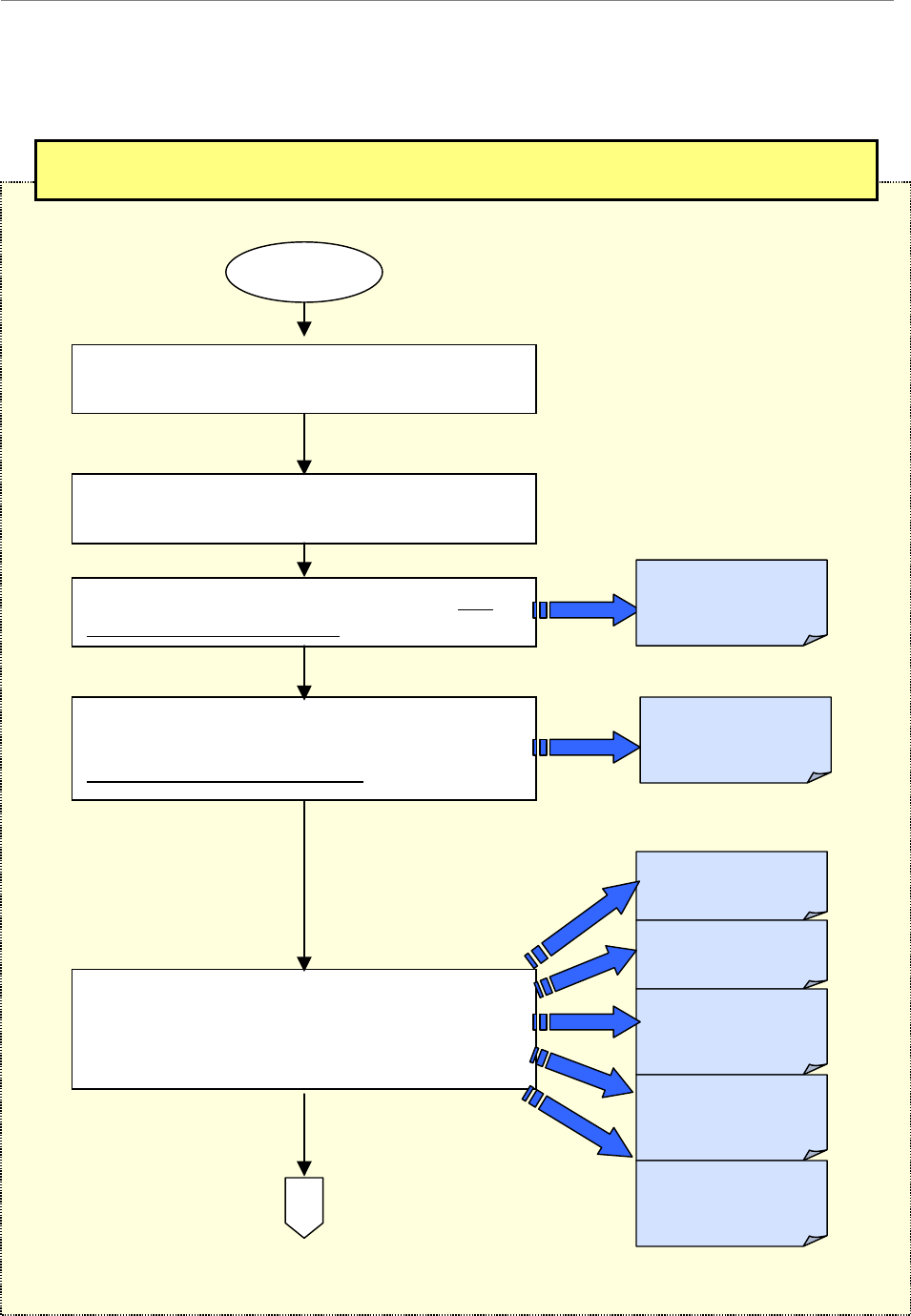
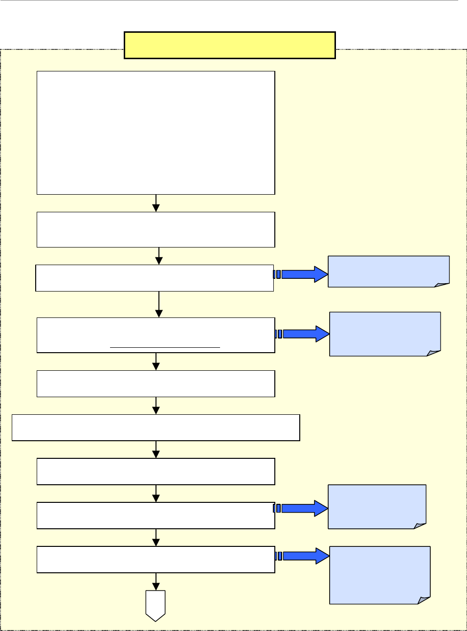
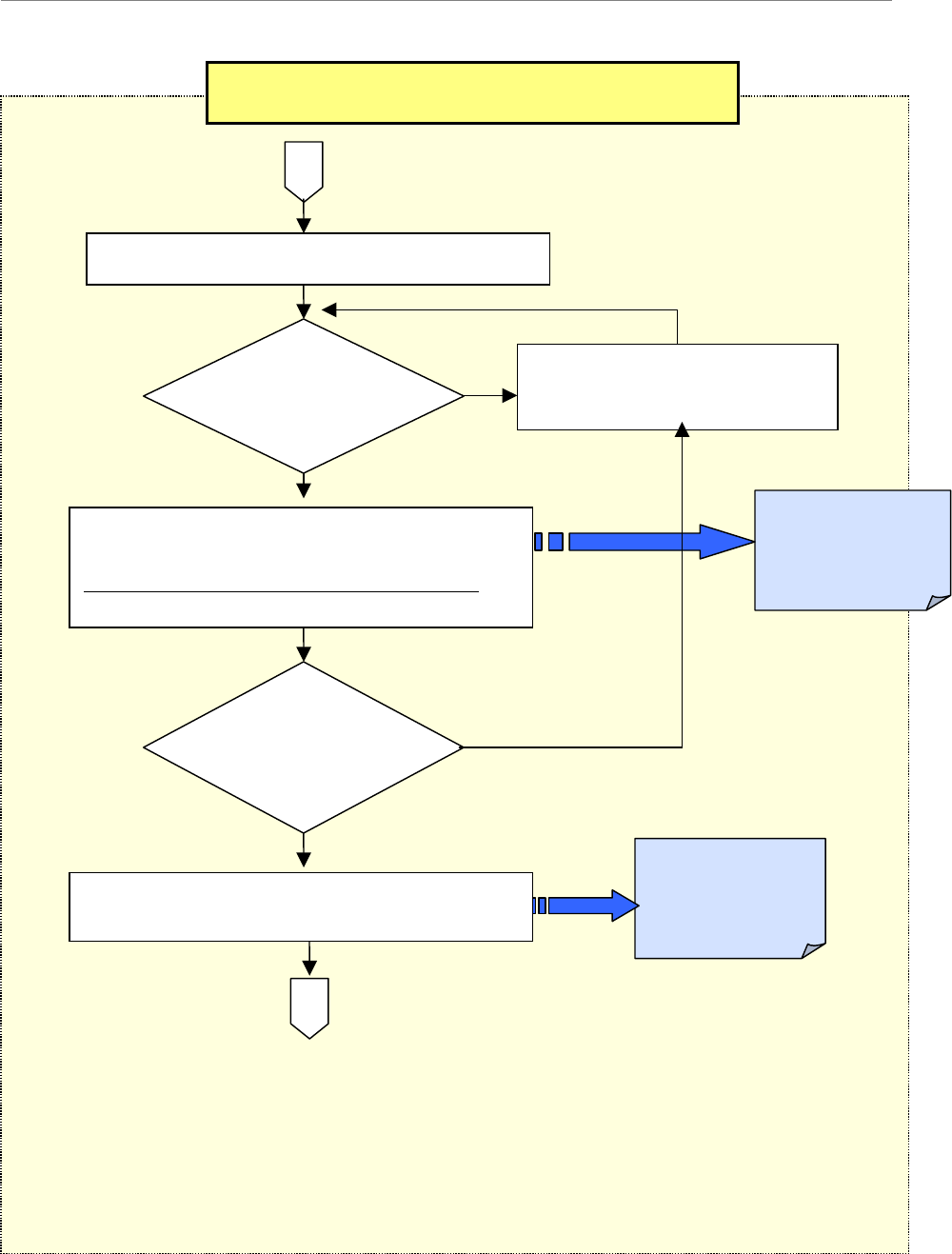
Figure 4: High Level I&C Process Flowchart
Phase I: Pre-installation - Site Selection, Design & Preparation
1 - Complete the Project Plan for this
deployment. <Program or Project Manager>
2 - Generate a coverage prediction map.
<RF Engineer>
3 - Conduct a site survey, filling out the Site
Candidate Evaluation Form.
4 – If this is a 2.4 GHz system, complete the
Interference Analysis, following the
Interference Sweep Procedure.
5 - Acquire information about the final site
selected by the customer. Physical site design
completed.
Appendix A:
Site Candidate
Evaluation For
m
Appendix B:
Interference Sweep
Procedure
Appendix C:
BTS Specifications
Appendix D:
RFS Data Sheets
Appendix E:
BTS Outdoor
Enclosure Mfrs.
Appendix F:
Rectifier/BBU
Manufacturers
A
BEGIN
Appendix G:
Sample Base Station
Drawin
g
Navini Networks, Inc. Ripwave Base Station I&C Guide
26
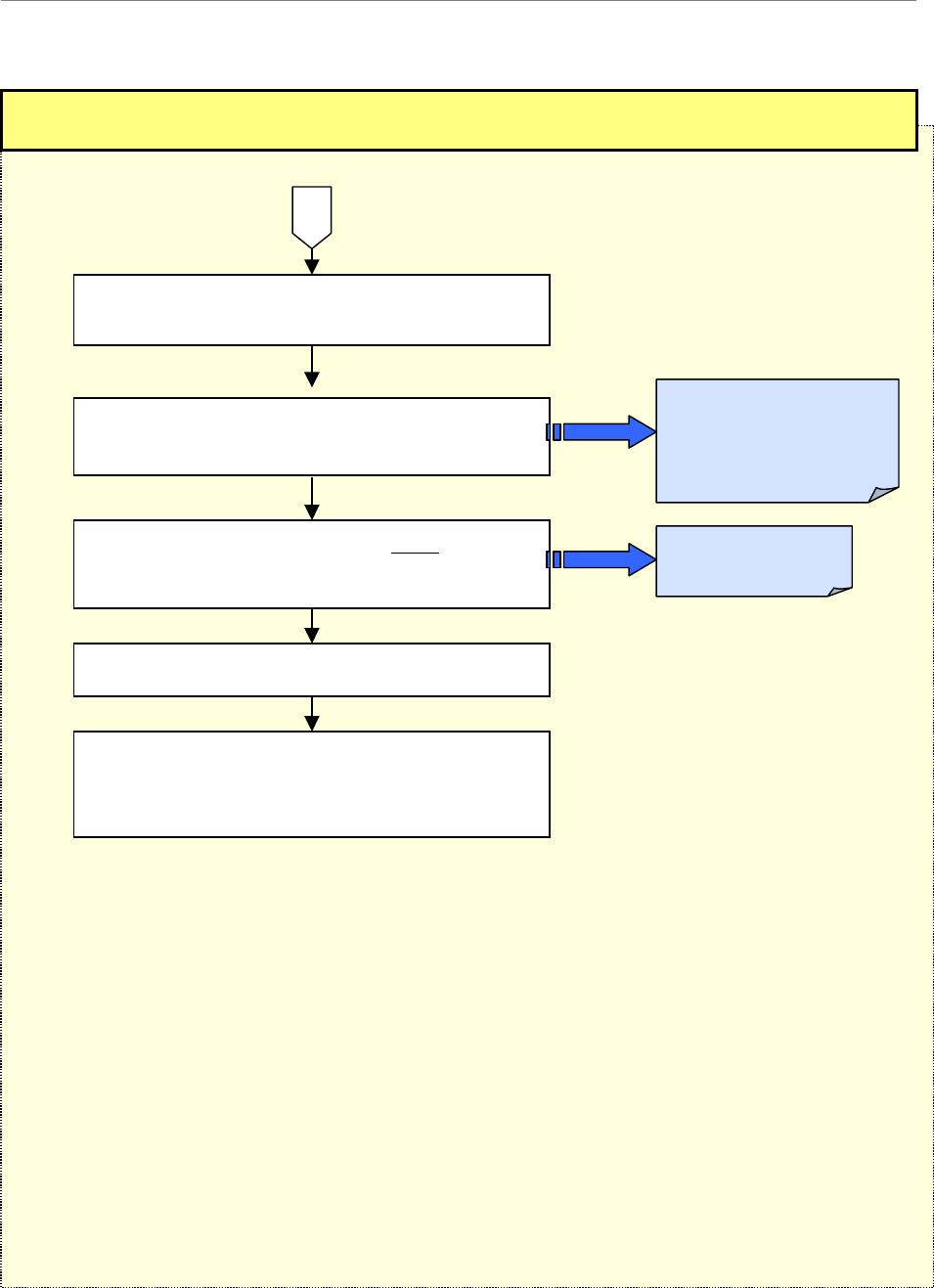
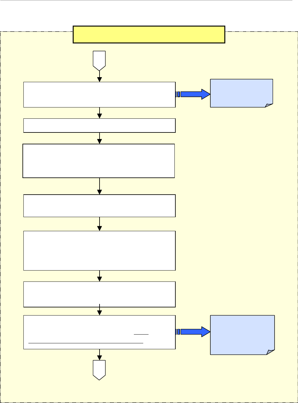
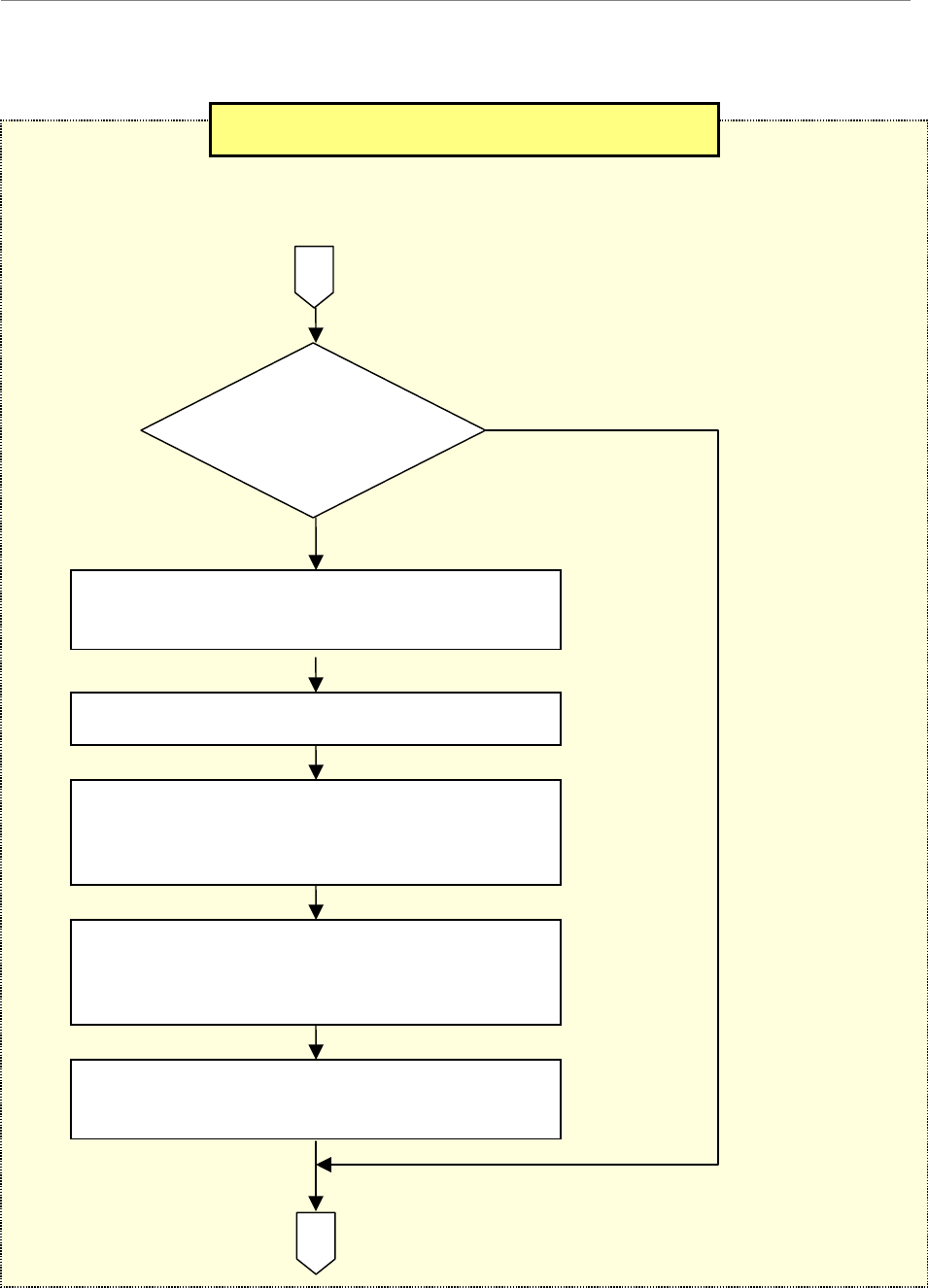
Phase I: Pre-installation - Site Selection, Design & Preparation, continued
6 - Complete the Network Architecture design.
<Network Planning>
8 - Develop a Bill of Materials (BoM).
<Customer >
9 - Acquire the materials. <Customer>
10 - Confirm the customer backhaul, EMS
Server, FTP Server, input power and
grounding are installed and operational at site.
Appendix I:
Sample BoM
7 - Antenna Power & Cable selection
p
rocedure.
A
Appendix H:
Antenna Power & Cable
Selection Procedure &
Form
Navini Networks, Inc. Ripwave Base Station I&C Guide
27
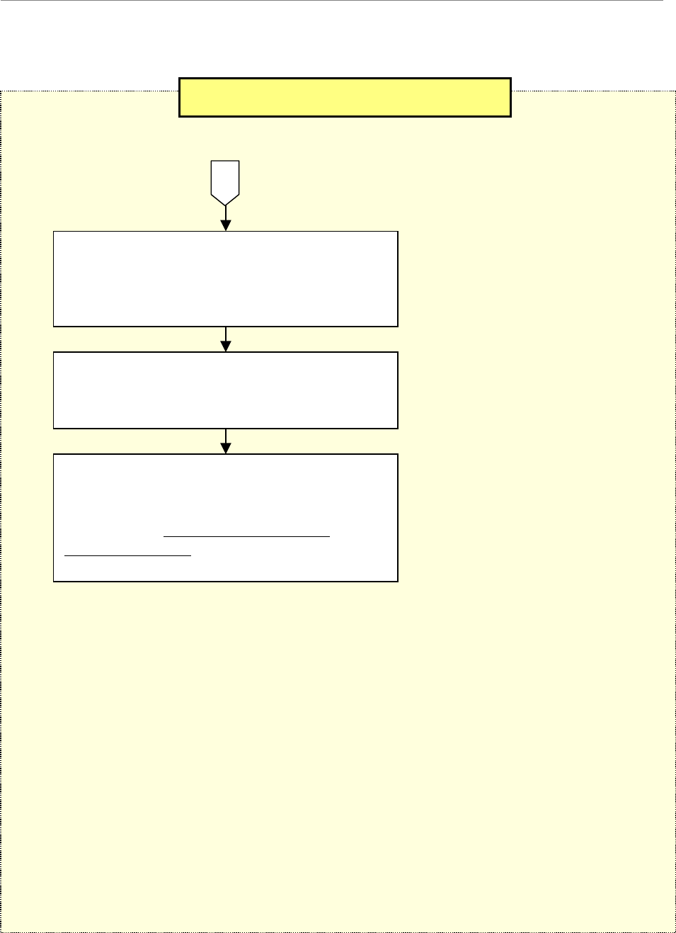
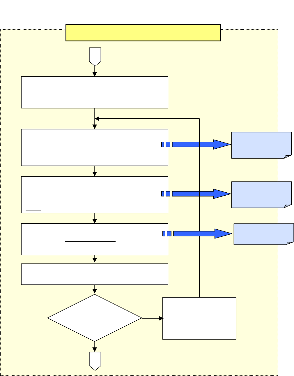
Phase II: Installation
1 - From the shipping containers received at
the customer site, gather Manufacturing’s
inventory sheet and test data that was collected
before the BTS & RFS equipment shipped.
Verify all equipment arrived (inventory it),
serial numbers match paperwork, and the test
data is available. Keep this as part of the
customer site records.
2 - Install all system buss bars and surge
p
rotecto
r
s.
4 - Install & sweep the RF cables. Record
results on the RFS System Test Form.
5 - Install & sweep the GPS cables.
6 - Test & install the data/power cable (Non-TTA BTS).
7 - If required, install the BTS mounting rack.
8 - Install the BTS chassis.
Appendix K:
RFS System Test
(
cables & RFS swee
p)
Appendix M:
Sample Tri-sector
BTS Grounding
Drawin
g
9 - Install & verify the BTS & RFS grounding.
A
3 - Cut cables. Install connectors on cables. Appendix J:
Install Connectors
Appendix L:
Chassis Alarms
Information
Navini Networks, Inc. Ripwave Base Station I&C Guide
28
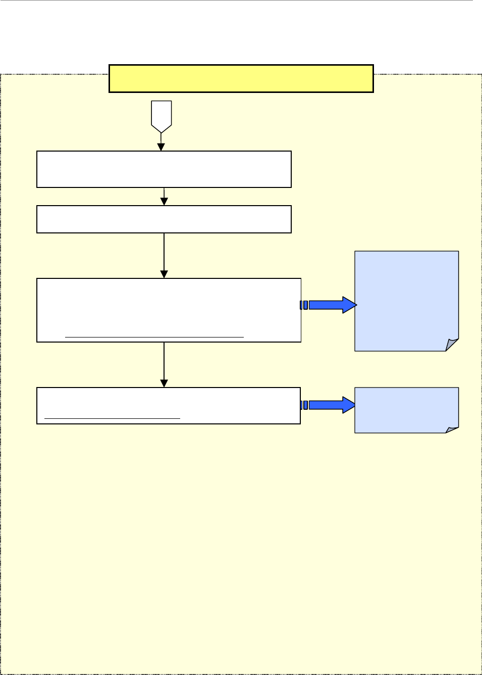
Phase II: Installation, continued
10 - Install & verify the DC input power
source to the BTS.
11 - Install the GPS antennas.
12 - Sweep the RFS. Record the results & the
RFS serial numbers on the RFS System Test
Form (same form as Step 3, Appendix K).
13 - Install the RFS & surge protectors and
Connect cables to the RFS.
14 - Sweep the installed RFS & cables to
verify connections & cable loss. Record results
on the RFS System Test Form (same form as
Ste
p
s 3 & 11, A
pp
endix K
)
.
15 - Verify that all cards are installed and
seated properly.
16 - Record the serial & version numbers of
the digital and RF/PA cards on the Base
Station Installation Certification Form.
Appendix N:
Sample Tri-sector
BTS Power Drawin
g
Appendix O:
Base Station
Installation
Certification Form
B
A
Navini Networks, Inc. Ripwave Base Station I&C Guide
29
Phase II: Installation, continued
17 - If required in the Responsibility
Assignment Matrix (RAM) portion of the
Project Plan, test the backhaul to the customer
demarcation point.
18 - Provide a printed package of the measured
results and equipment inventory to the
customer on-site.
19 - Go over the results using the printed
p
ackage and obtain customer sign-off on the
completion of the Installation portion of the
work. Use the Base Station Installation
Certification Form for sign-off (same form as
Ste
p
16
,
A
pp
endix P
)
.
B
Navini Networks, Inc. Ripwave Base Station I&C Guide
30
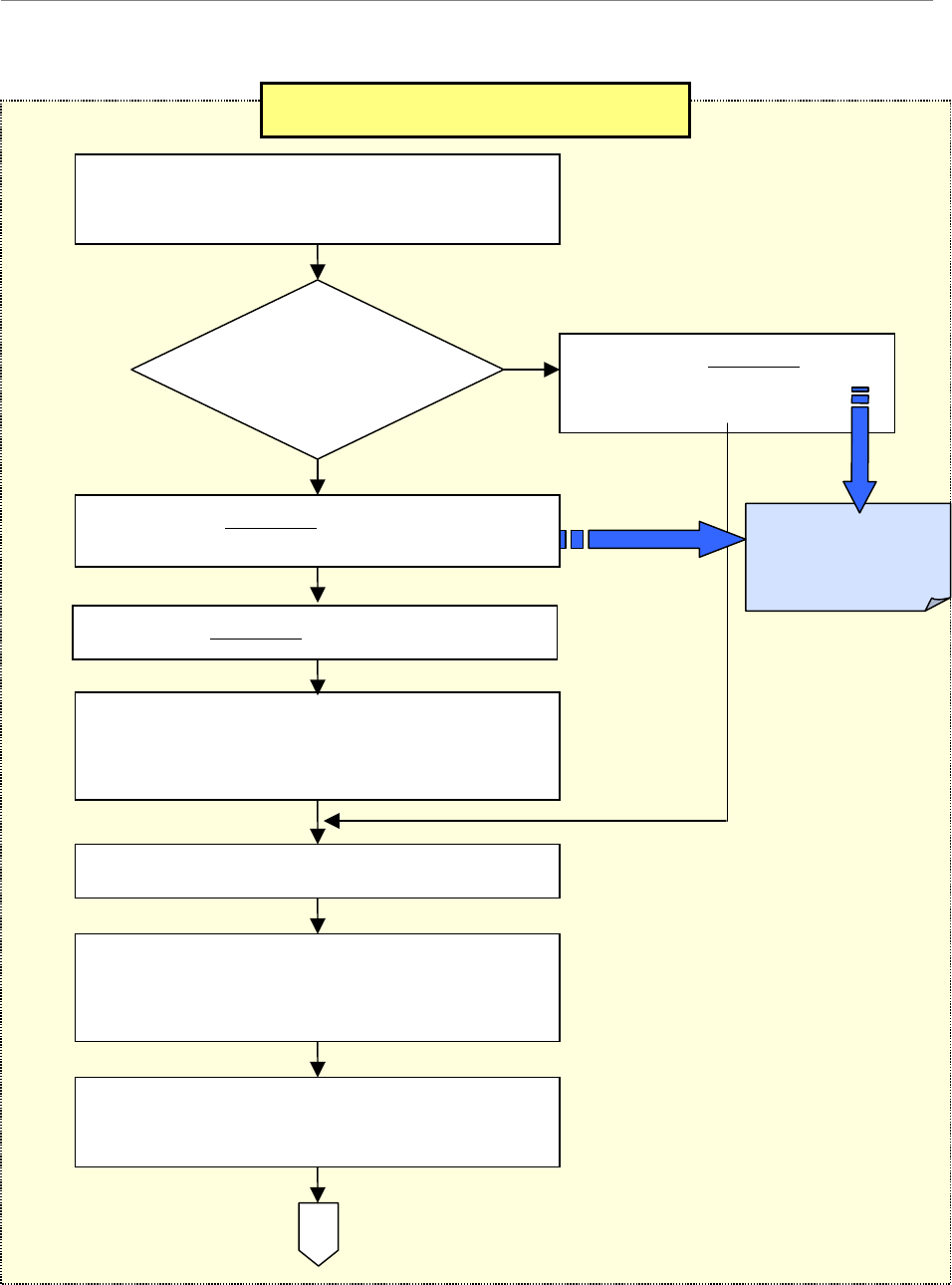
Phase III: Commissioning
1 - Review the customer’s network plans - i.e.,
ATM vs Ethernet backhaul.
3b - Install & configure the customer EMS
Server & Client.
5 - Enter the RFS configuration by running the
RFS script that shipped with the antenna
equipment.
2 - Are you using
the customer’s
EMS Server?
No
Yes
3a - Install & configure the
Test EMS Server & Client.
Appendix P:
Excel Configuration
Form
6 - Verify that all cables are connected.
7 - Power up the BTS & reconfigure the basic
Boot Line parameters through the serial port
on the CC card.
8 - After the BTS has been powered up at least
20 minutes.
A
4 - Install & configure the BTS in the EMS
Navini Networks, Inc. Ripwave Base Station I&C Guide
31
Phase III: Commissioning, continued
11b - Perform Base Station Calibration
Verification. Record the measurements on the
Base Station Calibration Verification Form
(
I&C Closeout Tool
)
10 - Did it pass
calibration? No
Yes
11a - Perform system
troubleshooting procedures.
Appendix Q:
Base Station
Calibration
Verification Form
B
A
12 - Did it pass
calibration
verification?
No
Yes
9 – Perform 3 calibrations.
Appendix R:
Single Antenna
Element Test
Procedure
13 - Perform the Single Antenna Element Test
p
rocedure.
Navini Networks, Inc. Ripwave Base Station I&C Guide
32
Phase III: Commissioning, continued
15 - Install & configure the Customer EMS
Server & Client.
C
B
16 – Configure BTS in the Customer EMS
19 - Perform calibration. Ensure successful
results 3 times.
Yes
17 - Enter the RFS configuration by running the
RFS script that shipped with the antenna
equipment.
18 – Verify EMS & BTS connectivity. Verify
that the latency between EMS and BTS is less
than 10 milliseconds
14 -Was the
Test EMS used?
No
Navini Networks, Inc. Ripwave Base Station I&C Guide
33
24b - Perform full Drive Study, and
record the results on the Drive Study
Form. This is used for tuning the
model (same form as Step 19,
Appendix X).
Phase III: Commissioning, continued
Yes
20 - Verify that the GPS & Constellation
Debugger are installed and operational on the
Drive Study laptop
21 - Perform the LOS Location (FTP) Test.
Complete 3 uploads & 3 downloads at 3
locations. Record the results on the FTP Test
For
m
.
(
I&C Closeout Form
)
D
C
No
25 -Results
adequate?
Appendix T:
Drive Study Form
Appendix S:
Location (FTP) Test
Procedure & For
m
26a - Adjust the RF
p
arameters and
troubleshoot.
Recalibrate BTS
22 - Perform the NLOS Location (FTP) Test.
Complete 3 uploads & 3 downloads at 3
locations. Record the results on the FTP Test
For
m
.
(
I&C Closeout Form
)
Appendix S:
Location (FTP) Test
Procedure & For
m
23 - Perform full Drive test Study. Record the
results on the Drive Study Form. (I&C Closeout
Form)
24 - Send test results to Navini Technical
Support.
Navini Networks, Inc. Ripwave Base Station I&C Guide
34
Phase III: Commissioning, continued
D
Appendix U:
Site Installation
Closeout
Documentation
Appendix V:
I&C Closeout form
26b- Verify system operation with multiple
Modems in use.
27 - Back up the EMS database.
28 - Gather all required documents & forms to
create a delivery package for the Customer sign-
off and for the Navini Techical Support database.
See Installation Closeout Documentation.
29 - Participate in the Customer sign-off of the
Customer Acceptance Form.
Appendix W:
Customer
Acce
p
tance For
m