Cisco Systems 53100936 Universal Small Cell 5310 3G Module User Manual usc5310 qsg
Cisco Systems Inc Universal Small Cell 5310 3G Module usc5310 qsg
User Manual

2
Revised: November, 2013, 78-21438-02
1 Before You Begin
A fully integrated, high-performance, low-cost third-generation
(3G) small cell, your Universal Small Cell (USC) 5310 module is
a licensed radio network extension that connects to the module
port of the Cisco Aironet 3600 Series access point, which is a
UL listed ITE product. This small cell module contains a
dedicated 3G small cell base station that delivers mobile services
indoors, while offloading traffic from the outdoor macro
network.
Using the standards-based technology of Home Node B (HNB),
the USC 5310 module provides 3G signals inside a building for
voice, data and messaging services for up to 16 simultaneous
users within a coverage area of approximately 7000 square feet
(650 square meters). The module supports Band 2/5 for the
American market and Band 1 for the rest of the world.
System Requirements
This module is designed for use with Cisco Aironet 3600 Series
access points. The module is not designed for use with other
access points. The USC 5310 module is supported on these
Cisco wireless LAN controllers:
•Cisco 5500 Series Wireless Controller
•Cisco 7500 Series Wireless Controller
•Cisco 8500 Series Wireless Controller
The USC 5310 is supported by the following software releases:
•Cisco Unified Wireless Network Software Release 7.6 or
later
•Cisco Universal Small Cell Software Release 3.3 or later
•Cisco Small Cell Solution Release 2.0 or later
3
Power Considerations
Installation of your small cell module requires an additional
6 watts to power the Cisco Aironet 3600 access point. With a
USC 5310 module installed, the access point requires the full
Power over Ethernet Plus (PoE+) of 25.5 Watts at the egress
switch port and a cable run of less than 300 feet (100 meters).
Power options for the access point include:
•IEEE 802.3at POE+ 25.5 W delivered from the upstream
Ethernet switch
•Cisco 3600 Series Power Injector (AIR-PWRINJ4=)
•Cisco 3600 Series local power supply (AIR-PWR-B=)
The USC 5310 module has a power limit circuitry that shuts
down the module if it draws more power than allowed.
Installation Considerations
Install your small cell:
•in a central location, in an area where people are most likely
to make calls
•away from windows, to avoid the signal leaking outside or
external signals leaking in
•in an open area with airflow; not in a closed cabinet which
reduces the signal strength
If you have thick internal walls, or metal, fire or rotating doors,
plan to place units at either side of the obstruction at a distance
shorter than 49 feet (15 m). Install a unit across from a corner
to provide coverage on both sides of the corner.
For more information, refer to the “Cisco Aironet AP Module
for Wireless Security and Spectrum Intellgence (WSSI)
Deployment Guide” at the following URL:
http://www.cisco.com/en/US/products/ps11983/
products_tech_note09186a0080bed15d.shtml.
4
2 Install Your USC 5310 Module
Follow these steps to install the USC 5310 module:
Step 1 Remove the module from the packaging.
Step 2 Power down the access point.
Step 3 Peel off the label from the back of the 3600 series access
point to reveal the module port connector.
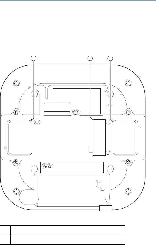
Figure 1 Backside of Cisco Aironet 3600 Access Point
1Openings for module’s antennas
2Label covering port connector
380755
12 1
5
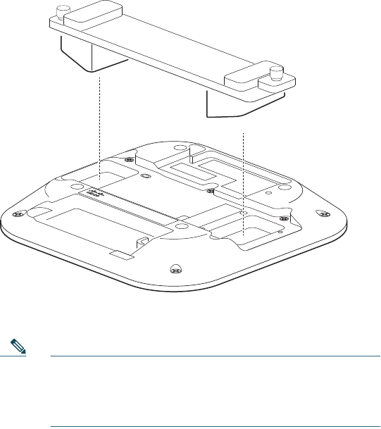
Step 4 Align the module connector with the connector on the
back of the access point and click the module into
place.
Figure 2 Installing Module in the Cisco Aironet 3600 Access
Point
Step 5 Screw down the thumb screws on the module.
Note If the screws are not tightened, the module will not be
recognized and may not operate correctly. Make sure
not to over-tighten the screws; they should be only
hand-tightened.
Step 6 Power up the access point. When the access point boots
up, it recognizes the module. No software
configuration is required.
Step 7 If necessary, mount the Cisco Aironet 3600 Series
access point, with the USC 5310 plug-in module
installed, using the universal bracket
(AIR-AP-BRACKET-2).
380756

6
Note The universal bracket works with electrical boxes, can
be used for wall mounting, and adapts to ceiling
installations. It leaves a larger gap between the
mounting surface and the access point, which allows
space for the USC 5310 plug-in module.
For more information, refer to “Access Point Mounting
Instructions” at the following URL:
http://www.cisco.com/en/US/docs/
wireless/access_point/mounting/guide/apmount.html
3 Verify Your Installation
After the USC 5310 module is installed in the access point and
powered up, it takes approximately ten minutes for the module
to initialize, download any necessary software and
configuration information, configure the radio frequency (RF)
parameters, and come into service.
Take note of the initialization sequence by noting the color and
activity of the LEDs on either side of the module. The module is
ready to use when the LEDs change to solid green.
7
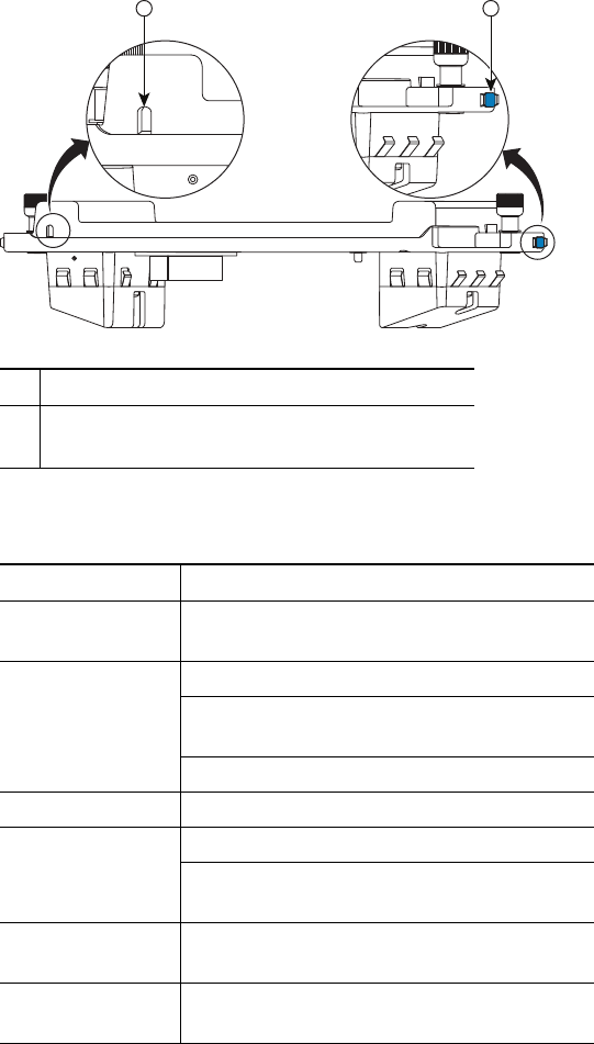
Figure 3 Cisco USC 5310 Module
1Reset button
2LED—the same LED indication displays on
both sides of the module
Table 1 USC 5310 LED Indications
LED Indication Small Cell State / Action
Off Unknown State or Off—Ensure power
supply is connected and turned on
Fast Blinking
Green
Initialization—Wait for action to complete
Temporarily out of service—Wait for
action to complete
Factory reset—Wait for action to complete
Green In service, no calls or data sessions
Slow Blinking
Green
In service, calls or data sessions are active
In service, experiencing congestion and
cannot accept more calls
Red blink 1 time
in 4 seconds
No physical LAN connection—Verify
connection with residential gateway
Red blink 1 time
in 4 seconds
No connection with router—Verify
residential gateway is operational
1 2
380757
8
4 Specifications
Part Numbers
•Band 1 deployments: USC5310-AI-K9
•Band 2/5 deployments: USC5310-BI-K9
Size
•Size: 8.46 x 2.5 x 1.97 in. (21.48 x 6.35 x 5 cm)
•Weight: 1 lb (less than 500 g)
Regulatory, Compliance and Safety
•CE Mark for USC5310-AI-K9
•FCC Part 15B Class B, Part 22 and Part 24 for
USC5310-BI-K9
Red blink 2 times
in 4 seconds
No Internet connection—Verify residential
gateway is connected to Internet
Red blink 3 times
in 4 seconds
RF issue, local interference or poor
QoS—Verify that phones are not too close
to unit
Red blink 4 times
in 4 seconds
Over-temperature—Verify location of unit
and that there is good air flow
Red Cannot create secure connection—Contact
operator
Internal fault—Contact operator
RF issue, cannot select an RF
profile—Verify whether another small cell
is located in close proximity and if so,
relocate the small cell
Provisioning failure—Contact operator
Table 1 USC 5310 LED Indications (continued)
LED Indication Small Cell State / Action
9
•For additional compliance information, refer to the
USC 5310 data sheet at the following URL:
http://www.cisco.com/en/US/prod/collateral/wireless/ps11035
/ps12975/ps13292/ps12976/data_sheet_c78-728548.html
•For additional safety information, refer to the “Cisco 3600
Series Access Points Getting Started Guide” at the following
URL: http://www.cisco.com/en/US/docs/wireless/
access_point/3600/quick/guide/ap3600getstart.html
5 Obtaining Documentation and
Submitting a Service Request
For information on obtaining documentation, submitting a
service request, and gathering additional information, see the
monthly What’s New in Cisco Product Documentation, which
also lists all new and revised Cisco technical documentation:
http://www.cisco.com/en/US/docs/general/whatsnew/whatsnew.
html
Subscribe to the What’s New in Cisco Product Documentation as
an RSS feed and set content to be delivered directly to your desktop
using a reader application. The RSS feeds are a free service. Cisco
currently supports RSS Version 2.0.
10
Federal Communication Commission Interference Statement
This device complies with Part 15 of the FCC Rules.
Operation is subject to the following two conditions:
(1) This device may not cause harmful interference, and
(2) this device must accept any interference received, including interference that
may cause undesired operation.
This equipment has been tested and found to comply with the limits for a Class B
digital device, pursuant to Part 15 of the FCC Rules. These limits are designed to
provide reasonable protection against harmful interference in a residential
installation. This equipment generates, uses and can radiate radio frequency energy
and, if not installed and used in accordance with the instructions, may cause harmful
interference to radio communications. However, there is no guarantee that
interference will not occur in a particular installation. If this equipment does cause
harmful interference to radio or television reception, which can be determined
by turning the equipment off and on, the user is encouraged to try to correct the
interference by one of the following measures:
(1) Reorient or relocate the receiving antenna.
(2) Increase the separation between the equipment and receiver.
(3) Connect the equipment into an outlet on a circuit different from that to which
the receiver is connected.
(4) Consult the dealer or an experienced radio/TV technician for help.
FCC Caution: Any changes or modifications not expressly approved by the
party responsible for compliance could void the user's authority to operate
this equipment.
This transmitter must not be co-located or operating in conjunction
with any other antenna or transmitter.
Radiation Exposure Statement:
This equipment complies with FCC radiation exposure limits set forth
for an uncontrolled environment. This equipment should be installed
and operated with minimum distance 20cm between the radiator & your body.
11
Industry Canada statement
This device complies with Industry Canada license-exempt RSS standard(s).
Operation is subject to the following two conditions:
(1) this device may not cause interference, and
(2) this device must accept any interference, including interference that may
cause undesired operation of the device.
Le présent appareil est conforme aux CNR d'Industrie Canada applicables aux
appareils radio exempts de licence. L'exploitation est autorisée aux deux conditions
suivantes:
(1) l'appareil ne doit pas produire de brouillage, et
(2) l'utilisateur de l'appareil doit accepter tout brouillage radioélectrique subi, même si le
brouillage est susceptible d'en compromettre le fonctionnement."
This Class B digital apparatus complies with Canadian ICES-003.
Cet appareil numérique de la classe B est conforme à la norme NMB-003 du Canada.
Radiation Exposure Statement:
This equipment complies with IC radiation exposure limits set forth for an
uncontrolled environment. This equipment should be installed and operated with
minimum distance 20cm between the radiator & your body.
Déclaration d'exposition aux radiations:
Cet équipement est conforme aux limites d'exposition aux rayonnements IC établies
pour un environnement non contrôlé. Cet équipement doit être installé et utilisé avec
un minimum de 20 cm de distance entre la source de rayonnement et votre corps.
Printed in the USA on recycled paper containing 10% postconsumer waste.
78-21438-02
Americas Headquarters
Cisco Systems, Inc.
San Jose, CA
Asia Pacific Headquarters
Cisco Systems (USA) Pte. Ltd.
Singapore
Europe Headquarters
Cisco Systems International BV Amsterdam,
The Netherlands
Cisco has more than 200 offices worldwide. Addresses, phone numbers, and fax numbers are listed on
the Cisco Website at www.cisco.com/go/offices.